EP4089824A1 - Electrochemical device and electronic device - Google Patents
Electrochemical device and electronic device Download PDFInfo
- Publication number
- EP4089824A1 EP4089824A1 EP21870476.5A EP21870476A EP4089824A1 EP 4089824 A1 EP4089824 A1 EP 4089824A1 EP 21870476 A EP21870476 A EP 21870476A EP 4089824 A1 EP4089824 A1 EP 4089824A1
- Authority
- EP
- European Patent Office
- Prior art keywords
- electrochemical device
- bonding
- electrode assembly
- bonding layer
- bonding regions
- Prior art date
- Legal status (The legal status is an assumption and is not a legal conclusion. Google has not performed a legal analysis and makes no representation as to the accuracy of the status listed.)
- Pending
Links
Images


Classifications
-
- H—ELECTRICITY
- H01—ELECTRIC ELEMENTS
- H01M—PROCESSES OR MEANS, e.g. BATTERIES, FOR THE DIRECT CONVERSION OF CHEMICAL ENERGY INTO ELECTRICAL ENERGY
- H01M50/00—Constructional details or processes of manufacture of the non-active parts of electrochemical cells other than fuel cells, e.g. hybrid cells
- H01M50/40—Separators; Membranes; Diaphragms; Spacing elements inside cells
- H01M50/46—Separators, membranes or diaphragms characterised by their combination with electrodes
- H01M50/461—Separators, membranes or diaphragms characterised by their combination with electrodes with adhesive layers between electrodes and separators
-
- H—ELECTRICITY
- H01—ELECTRIC ELEMENTS
- H01M—PROCESSES OR MEANS, e.g. BATTERIES, FOR THE DIRECT CONVERSION OF CHEMICAL ENERGY INTO ELECTRICAL ENERGY
- H01M10/00—Secondary cells; Manufacture thereof
- H01M10/04—Construction or manufacture in general
- H01M10/0431—Cells with wound or folded electrodes
-
- H—ELECTRICITY
- H01—ELECTRIC ELEMENTS
- H01M—PROCESSES OR MEANS, e.g. BATTERIES, FOR THE DIRECT CONVERSION OF CHEMICAL ENERGY INTO ELECTRICAL ENERGY
- H01M10/00—Secondary cells; Manufacture thereof
- H01M10/04—Construction or manufacture in general
- H01M10/0463—Cells or batteries with horizontal or inclined electrodes
-
- H—ELECTRICITY
- H01—ELECTRIC ELEMENTS
- H01M—PROCESSES OR MEANS, e.g. BATTERIES, FOR THE DIRECT CONVERSION OF CHEMICAL ENERGY INTO ELECTRICAL ENERGY
- H01M50/00—Constructional details or processes of manufacture of the non-active parts of electrochemical cells other than fuel cells, e.g. hybrid cells
- H01M50/40—Separators; Membranes; Diaphragms; Spacing elements inside cells
- H01M50/409—Separators, membranes or diaphragms characterised by the material
- H01M50/411—Organic material
- H01M50/414—Synthetic resins, e.g. thermoplastics or thermosetting resins
-
- H—ELECTRICITY
- H01—ELECTRIC ELEMENTS
- H01M—PROCESSES OR MEANS, e.g. BATTERIES, FOR THE DIRECT CONVERSION OF CHEMICAL ENERGY INTO ELECTRICAL ENERGY
- H01M50/00—Constructional details or processes of manufacture of the non-active parts of electrochemical cells other than fuel cells, e.g. hybrid cells
- H01M50/40—Separators; Membranes; Diaphragms; Spacing elements inside cells
- H01M50/409—Separators, membranes or diaphragms characterised by the material
- H01M50/449—Separators, membranes or diaphragms characterised by the material having a layered structure
-
- H—ELECTRICITY
- H01—ELECTRIC ELEMENTS
- H01M—PROCESSES OR MEANS, e.g. BATTERIES, FOR THE DIRECT CONVERSION OF CHEMICAL ENERGY INTO ELECTRICAL ENERGY
- H01M50/00—Constructional details or processes of manufacture of the non-active parts of electrochemical cells other than fuel cells, e.g. hybrid cells
- H01M50/40—Separators; Membranes; Diaphragms; Spacing elements inside cells
- H01M50/489—Separators, membranes, diaphragms or spacing elements inside the cells, characterised by their physical properties, e.g. swelling degree, hydrophilicity or shut down properties
-
- H—ELECTRICITY
- H01—ELECTRIC ELEMENTS
- H01M—PROCESSES OR MEANS, e.g. BATTERIES, FOR THE DIRECT CONVERSION OF CHEMICAL ENERGY INTO ELECTRICAL ENERGY
- H01M10/00—Secondary cells; Manufacture thereof
- H01M10/05—Accumulators with non-aqueous electrolyte
- H01M10/052—Li-accumulators
-
- H—ELECTRICITY
- H01—ELECTRIC ELEMENTS
- H01M—PROCESSES OR MEANS, e.g. BATTERIES, FOR THE DIRECT CONVERSION OF CHEMICAL ENERGY INTO ELECTRICAL ENERGY
- H01M10/00—Secondary cells; Manufacture thereof
- H01M10/05—Accumulators with non-aqueous electrolyte
- H01M10/058—Construction or manufacture
- H01M10/0585—Construction or manufacture of accumulators having only flat construction elements, i.e. flat positive electrodes, flat negative electrodes and flat separators
-
- H—ELECTRICITY
- H01—ELECTRIC ELEMENTS
- H01M—PROCESSES OR MEANS, e.g. BATTERIES, FOR THE DIRECT CONVERSION OF CHEMICAL ENERGY INTO ELECTRICAL ENERGY
- H01M10/00—Secondary cells; Manufacture thereof
- H01M10/05—Accumulators with non-aqueous electrolyte
- H01M10/058—Construction or manufacture
- H01M10/0587—Construction or manufacture of accumulators having only wound construction elements, i.e. wound positive electrodes, wound negative electrodes and wound separators
-
- H—ELECTRICITY
- H01—ELECTRIC ELEMENTS
- H01M—PROCESSES OR MEANS, e.g. BATTERIES, FOR THE DIRECT CONVERSION OF CHEMICAL ENERGY INTO ELECTRICAL ENERGY
- H01M50/00—Constructional details or processes of manufacture of the non-active parts of electrochemical cells other than fuel cells, e.g. hybrid cells
- H01M50/40—Separators; Membranes; Diaphragms; Spacing elements inside cells
- H01M50/409—Separators, membranes or diaphragms characterised by the material
- H01M50/449—Separators, membranes or diaphragms characterised by the material having a layered structure
- H01M50/457—Separators, membranes or diaphragms characterised by the material having a layered structure comprising three or more layers
-
- Y—GENERAL TAGGING OF NEW TECHNOLOGICAL DEVELOPMENTS; GENERAL TAGGING OF CROSS-SECTIONAL TECHNOLOGIES SPANNING OVER SEVERAL SECTIONS OF THE IPC; TECHNICAL SUBJECTS COVERED BY FORMER USPC CROSS-REFERENCE ART COLLECTIONS [XRACs] AND DIGESTS
- Y02—TECHNOLOGIES OR APPLICATIONS FOR MITIGATION OR ADAPTATION AGAINST CLIMATE CHANGE
- Y02E—REDUCTION OF GREENHOUSE GAS [GHG] EMISSIONS, RELATED TO ENERGY GENERATION, TRANSMISSION OR DISTRIBUTION
- Y02E60/00—Enabling technologies; Technologies with a potential or indirect contribution to GHG emissions mitigation
- Y02E60/10—Energy storage using batteries
-
- Y—GENERAL TAGGING OF NEW TECHNOLOGICAL DEVELOPMENTS; GENERAL TAGGING OF CROSS-SECTIONAL TECHNOLOGIES SPANNING OVER SEVERAL SECTIONS OF THE IPC; TECHNICAL SUBJECTS COVERED BY FORMER USPC CROSS-REFERENCE ART COLLECTIONS [XRACs] AND DIGESTS
- Y02—TECHNOLOGIES OR APPLICATIONS FOR MITIGATION OR ADAPTATION AGAINST CLIMATE CHANGE
- Y02P—CLIMATE CHANGE MITIGATION TECHNOLOGIES IN THE PRODUCTION OR PROCESSING OF GOODS
- Y02P70/00—Climate change mitigation technologies in the production process for final industrial or consumer products
- Y02P70/50—Manufacturing or production processes characterised by the final manufactured product
Definitions
- This application relates to the technical field of energy storage, and in particular, to an electrochemical device and an electronic device containing the electrochemical device.
- Electrochemical devices (such as a battery) are widely used in electronic devices such as an electronic mobile device, an electric tool, and an electric vehicle. With the development of such electronic devices, people pose higher requirements on the cycle performance of the electrochemical devices.
- the electrode assembly includes electrode plates and a separator disposed between adjacent electrode plates.
- the separator includes a porous substrate and a first bonding layer disposed on a surface of the porous substrate.
- the first bonding layer includes a plurality of first bonding regions spaced apart from each other.
- a thickness direction of the electrode assembly is defined as a first direction. In the first direction, a circumscribed rectangle of a projection of the electrode assembly possesses a diagonal line and a first side. An angle between the diagonal line and the first side is ⁇ 1 . An angle between a projection of each of the plurality of first bonding regions and the first side is ⁇ 2 , where ⁇ 1 /2 ⁇ ⁇ 2 ⁇ ( ⁇ 1 /2 + 45°).
- the first bonding layer disposed on the separator according to this application includes a plurality of spaced first bonding regions to improve the interfacial adhesion between the separator and the electrode plate.
- a gap between two adjacent first bonding regions reserves a space for transmitting the electrolytic solution, thereby meeting the requirement of achieving a trade-off between the interfacial adhesion and the electrolyte transmission.
- each first bonding region can form a relatively stable triangular fixing relationship with an end portion and a lateral portion of the electrode assembly, thereby further increasing the deformation resistance and cycle performance of the electrochemical device.
- the separator further includes a second bonding layer.
- the porous substrate is located between the first bonding layer and the second bonding layer.
- the second bonding layer includes a plurality of second bonding regions spaced apart from each other. Therefore, a gap between two adjacent second bonding regions can also be used as a channel for transmitting the electrolytic solution, thereby further improving the performance of transmitting the electrolytic solution.
- an angle between a projection of each of the plurality of second bonding regions and the projection of each of the plurality of first bonding regions is ⁇ 3 , where 0° ⁇ ⁇ 3 ⁇ 180°. Therefore, the second bonding regions are also tilted, so that the bonding force of the second bonding layer is also continuously distributed in the direction of the first side, thereby further increasing the deformation resistance of the electrochemical device.
- ⁇ 3 180° - 2 ⁇ 2 .
- ⁇ 2 ⁇ 1 . It is further defined that ⁇ 2 is equal to ⁇ 1 , so that each first bonding region can form the stablest triangular fixing relationship with a second end portion and the lateral portion of the electrode assembly, thereby further increasing the deformation resistance of the electrode assembly.
- a direction from one of the first bonding regions to another adjacent first bonding region is defined as a second direction.
- a width of each of the plurality of first bonding regions is d 1 mm
- a distance between adjacent two of the plurality of first bonding regions is d 2 mm
- d 1 and d 2 satisfy: 0.1 ⁇ d 1 ⁇ 10, and 0.1 ⁇ d 2 ⁇ 10.
- d 2 When d 2 is exceptionally small, the space available for transmitting the electrolytic solution is also reduced, thereby deteriorating infiltration of the electrolytic solution.
- d 1 When d 2 is exceptionally large, d 1 is reduced accordingly, thereby also reducing the bonding force between the first bonding layer and the electrode plate and reducing the deformation resistance accordingly.
- a direction from one of the first bonding regions to another adjacent first bonding region is defined as a second direction.
- a width of the first bonding region is d 1 mm
- a distance between the adjacent first bonding regions is d 2 mm
- d 1 and d 2 satisfy: 0.1 ⁇ d 1 /d 2 ⁇ 5.
- a thickness of the first bonding layer is t 1 ⁇ m, and 0.15 ⁇ t 1 d 1 /(d 1 + d 2 ) ⁇ 2.
- t 1 d 1 /(d 1 + d 2 ) is exceptionally small, the proportion of a diffusion area of the first bonding layer softened by heating is reduced, thereby also reducing the bonding force between the first bonding layer and the electrode plate, and reducing the deformation resistance accordingly.
- t 1 d 1 /(d 1 + d 2 ) is exceptionally large, the proportion of the diffusion area of the first bonding layer softened by heating is increased, thereby also reducing the space available for transmitting the electrolytic solution and deteriorating infiltration of the electrolytic solution.
- the thickness of the first bonding layer is t 1 ⁇ m, and 0.1 ⁇ t 1 ⁇ 6.
- t 1 is exceptionally small, the bonding force between the first bonding layer and the electrode plate is reduced.
- t 1 is exceptionally large, thereby reducing overall air permeability of the separator and resulting in poor transmission of the electrolytic solution.
- the plurality of the first bonding regions are parallel to each other.
- an angle may exist between two adjacent first bonding regions, where the angle is -5° to +5°.
- each of the plurality of first bonding regions is continuous or discontinuous. Gaps between different sections of each discontinuous first bonding region may also be used as a channel for transmitting the electrolytic solution, thereby further improving the performance of transmitting the electrolytic solution.
- shapes of the projection of the electrode assembly include a rectangle, an arc, or an L shape. Therefore, the electrochemical device can fit with the shape of the internal space of the electronic device, so as to make full use of the space in the electronic device and increase the capacity of the electrochemical device.
- the electrode assembly further includes tabs electrically connected to the electrode plates. Projections of the tabs in the first direction protrude from an opposite side of the first side, so that the tabs can be connected to an external component conveniently.
- structures of the electrode assembly include a wound structure or a stacked structure.
- the porous substrate includes a polymer film, a multilayer polymer film, or a non-woven fabric, which, in each case, is formed by at least one of polyolefin, polyvinylidene difluoride, polyethylene terephthalate, cellulose, polyimide, polyamide, spandex, or polyphthalamide.
- polymers are of high thermal stability and make it easy to coat the porous substrate with the first bonding layer.
- the polymers are flexible and easily bendable.
- the first bonding layer includes a bonding material.
- the bonding material includes at least one of poly(vinylidene difluoride-co-hexafluoropropylene), poly(vinylidene difluoride-co-trichloroethylene), polymethyl methacrylate, polyacrylic acid, polyacrylic acid sodium salt, polyacrylonitrile, polyvinylpyrrolidone, polyvinyl acetate, poly(ethylene-co-vinyl acetate), polyimide, polyethylene oxide, cellulose acetate, cellulose acetate butyrate, cellulose acetate propionate, cyanoethyl pullulan, cyanoethyl polyvinyl alcohol, cyanoethyl cellulose, cyanoethyl sucrose, pullulan, sodium carboxymethyl cellulose, lithium carboxymethyl cellulose, poly(acrylonitrile-co-styrene-co-butadiene), polyvinyl alcohol, polyvinyl ether
- This application further provides an electronic device, including the electrochemical device described above.
- An electrochemical device generally includes electrode plates and a separator disposed between adjacent electrode plates.
- a separator of high bonding performance is used so that the adjacent electrode plates and the separator are bonded firmly together to ensure high interfacial adhesion between the separator and the electrode plates, and to suppress expansion deformation caused by gassing inside the electrochemical device.
- the separator of high bonding performance makes interstices smaller between the separator and the electrode plate, and makes the electrode plate hardly permeable by the electrolytic solution.
- uneven distribution of the electrolytic solution is more prone to occur at a corner region of the electrode assembly, thereby leading to purple-speck lithium plating during cycles and impairing the cycle performance of the electrochemical device.
- an embodiment of this application provides an electrochemical device 100, including a housing 10, an electrode assembly 20 (shown in FIG. 5 and FIG. 6 ), an electrolytic solution, a first tab 30 and a second tab 40.
- the electrode assembly 20 and the electrolytic solution are accommodated in the housing 10.
- the electrochemical device 100 shown in FIG. 5 and FIG. 6 includes one electrode assembly 20.
- the electrochemical device 100 may include a plurality of electrode assemblies 20 connected in series instead, without being limited in this application.
- the electrode assembly 20 includes electrode plates and a separator 23 disposed between adjacent electrode plates.
- the electrode plates include a first electrode plate 21 and a second electrode plate 22.
- the separator 23 is disposed between the first electrode plate 21 and the second electrode plate 22.
- the separator 23 is configured to prevent direct contact between the first electrode plate 21 and the second electrode plate 22, where the direct contact may cause a short circuit.
- the electrode assembly 20 is obtained by winding the first electrode plate 21, the separator, and the second electrode plate 22. In other words, the electrode assembly 20 is a wound structure.
- the electrode assembly 20 may be obtained by stacking the first electrode plate 21, the separator, and the second electrode plate 22. In other words, the electrode assembly 20 is a stacked structure.
- the first tab 30 and the second tab 40 are electrically connected to the electrode assembly 20, respectively, and protrude from the housing 10 to connect to an external component (not shown in the drawing).
- the first electrode plate 21 includes a first current collector 211 and a first active material layer 212 disposed on a surface of the first current collector 211.
- the first tab 30 is electrically connected to the first current collector 211.
- the second electrode plate 22 includes a second current collector 221 and a second active material layer 222 disposed on a surface of the second current collector 221.
- the second tab 40 is electrically connected to the second current collector 221.
- the first electrode plate 21 is a positive electrode plate
- the second electrode plate 22 is a negative electrode plate.
- the housing 10 may be a packaging bag obtained by sealing with a sealing film.
- the electrochemical device 100 may be a pouch-type battery.
- the housing 10 includes a body portion 11 and a sealing portion 12.
- the body portion 11 is configured to accommodate the electrode assembly 20 and the electrolytic solution.
- the sealing portion 12 is connected to the body portion 11.
- the first tab 30 and the second tab 40 protrude out of the sealing portion 12.
- the body portion 11 includes a top surface 111, a bottom surface 112, an upper surface 113, a lower surface (not shown), a first lateral surface 114, and a second lateral surface 115.
- the top surface 111 is opposite to the bottom surface 112.
- the upper surface 113 is opposite to the lower surface, and is connected between the top surface 111 and the bottom surface 112.
- the first lateral surface 114 is opposite to the second lateral surface 115, and is connected between the top surface 111 and the bottom surface 112.
- the sealing portion 12 is connected to the top surface 111.
- the electrochemical device 100 may be a steel- or aluminum-shell battery or the like instead. The type of the electrochemical device is not limited in this application.
- the separator 23 includes a porous substrate 230 and a first bonding layer 231 disposed on a surface of the porous substrate 230.
- the first bonding layer 231 bonds with the first electrode plate 21.
- the first bonding layer 231 may bond with the second electrode plate 22 instead.
- the first bonding layer 231 includes a plurality of first bonding regions 2311 spaced apart from each other. In other words, adjacent two of the plurality of first bonding regions 2311 are interspaced with a gap G 1 . In some embodiments, the plurality of first bonding regions 2311 are parallel to each other. Understandably, when two components are referred to as being parallel to each other, the two components are not necessarily parallel to each other exactly, but an angle may exist between the two components, where the angle is -5° to +5°.
- the thickness direction (that is, the direction from the upper surface 113 to the lower surface), the length direction (that is, the direction from the bottom surface 112 to the top surface 111), and the width direction (that is, the direction from the first lateral surface 114 to the second lateral surface 115) of the electrode assembly 20 are a first direction D 1 , a third direction D 3 , and a fourth direction D 4 , respectively.
- the third direction D 3 is the direction in which the first tab 30 and the second tab 40 protrude.
- the projection 200 of the electrode assembly 20 in the first direction D 1 , is rectangular, and possesses a first side 201, a second side 202, and a diagonal line 203 connected to both the first side 201 and the second side 202.
- the electrode assembly 20 possesses a first end portion 20a, a second end portion 20b, and a lateral portion 20c connected between the first end portion 20a and the second end portion 20b.
- the first end portion 20a is a head of the electrode assembly 20, and is a portion at which the first tab 30 and the second tab 40 are disposed.
- the second end portion 20b is an ending of the electrode assembly 20, where the ending is opposite to the head.
- the projection of the second end portion 20b in the first direction D 1 forms the first side 201.
- the projection of the lateral portion 20c in the first direction D 1 forms the second side 202.
- the projections of the first tab 30 and the second tab 40 in the first direction D 1 protrude from the opposite side of the first side 201, so that the first tab 30 and the second tab 40 can be electrically connected to an external component conveniently.
- an angle between the diagonal line 203 and the first side 201 is ⁇ 1 .
- the diagonal line 203 of the circumscribed rectangle R tilts against the first side 201, and therefore, 0° ⁇ ⁇ 1 ⁇ 90°.
- the angle between the projection of each of the plurality of first bonding regions 2311 and the first side 201 is ⁇ 2 .
- ⁇ 1 and ⁇ 2 satisfy: ⁇ 1 /2 ⁇ ⁇ 2 ⁇ ( ⁇ 1 /2 + 45°).
- each first bonding region 2311 may be strip-shaped and disposed on the surface of the porous substrate 230. That is, each of the plurality of first bonding regions 2311 is continuous. In this case, the projection of each of the plurality of first bonding regions 2311 is also strip-shaped. The angle ⁇ 2 between the projection of each of the plurality of first bonding regions 2311 and the first side 201 is the angle between the strip-shaped projection and the first side 201. As shown in FIG. 9 , in another embodiment, each of the plurality of first bonding regions 2311 may be discontinuous instead, for example, may be disposed on the surface of the porous substrate 230 in shapes of a plurality of blocks or islands.
- the projection of each of the plurality of first bonding regions 2311 is also in the shape of a plurality of blocks or islands.
- the angle ⁇ 2 between the projection of each of the plurality of first bonding regions 2311 and the first side 201 is the angle between a connection line of the projections of the blocks or islands and the first side 201.
- Gaps G 2 also exist between sections of each discontinuous first bonding region 2311, and can be used as a channel for transmitting the electrolytic solution, thereby further improving the performance of transmitting the electrolytic solution.
- the first bonding layer 231 disposed on the separator according to this application includes a plurality of spaced first bonding regions 2311.
- the plurality of first bonding regions 2311 can bond with the first electrode plate 21 or the second electrode plate 22, so as to improve the interfacial adhesion between the separator 23 and the electrode plate and suppress the expansion deformation caused by the gassing inside the electrochemical device 100. This increases the deformation resistance of the electrochemical device 100, reduces the hazards of deformation and structural disruption of the electrode assembly, and keeps smoothness of the entire conductive network in the electrode assembly 20, thereby improving the cycle performance of the electrochemical device 100.
- a gap G 1 exists between adjacent two of the plurality of first bonding regions 2311 to reserve a space for transmitting the electrolytic solution.
- the electrolytic solution After the electrolytic solution is injected, the electrolytic solution can flow through the gap G 1 and infiltrate the electrode plate thoroughly, thereby also helping to improve the cycle performance of the electrochemical device 100.
- the electrochemical device 100 according to this application achieves a trade-off between interfacial adhesion and the required capability of transmitting the electrolytic solution.
- the bonding force of the first bonding layer 231 is continuously distributed in the direction of the first side 201. That is, the bonding force between the separator 23 and the electrode plate is continuously distributed in the direction of the first side 201, thereby increasing the deformation resistance of the electrochemical device 100 and improving the cycle performance.
- each first bonding region 2311 can form a relatively stable triangular fixing relationship with the second end portion 20b and the lateral portion 20c of the electrode assembly 20, thereby further increasing the deformation resistance of the electrochemical device 100 and improving the cycle performance.
- the shape of the projection 200 of the electrode assembly 20 is not limited to a rectangle, and may be other irregular shapes instead.
- shapes of the projection 200 of the electrode assembly 20 in the first direction D 1 include an arc or an L shape.
- the circumscribed rectangle R of the projection 200 of the electrode assembly 20 also possesses a first side 201, a second side 202, and a diagonal line 203 connected between the first side 201 and the second side 202. Understandably, as shown in FIG. 2 , when the projection 200 of the electrode assembly 20 is rectangular, the circumscribed rectangle R of the projection 200 is the projection 200 itself.
- the porous substrate 230 includes a polymer film, a multilayer polymer film, or a non-woven fabric, which, in each case, is formed by at least one of polyolefin, polyvinylidene difluoride, polyethylene terephthalate, cellulose, polyimide, polyamide, spandex, or polyphthalamide.
- polymers possess high thermal stability, and facilitate surface treatment, thereby making it easy to coat the porous substrate 230 with the first bonding layer 231.
- such polymers are highly flexible and bendable.
- the first bonding layer 231 includes a bonding material.
- the bonding material includes at least one of the following polymers: poly(vinylidene difluoride-co-hexafluoropropylene), poly(vinylidene difluoride-co-trichloroethylene), polymethyl methacrylate, polyacrylic acid, polyacrylic acid sodium salt, polyacrylonitrile, polyvinylpyrrolidone, polyvinyl acetate, poly(ethylene-co-vinyl acetate), polyimide, polyethylene oxide, cellulose acetate, cellulose acetate butyrate, cellulose acetate propionate, cyanoethyl pullulan, cyanoethyl polyvinyl alcohol, cyanoethyl cellulose, cyanoethyl sucrose, pullulan, sodium carboxymethyl cellulose, lithium carboxymethyl cellulose, poly(acrylonitrile-co-styrene-co-butadiene), polyvinyl alcohol, polyvin
- the separator 23 further includes a second bonding layer 232.
- the porous substrate 230 is located between the first bonding layer 231 and the second bonding layer 232.
- the second bonding layer 232 bonds with the second electrode plate 22.
- the second bonding layer 232 includes a plurality of second bonding regions 2321 spaced from each other. In other words, two adjacent second bonding regions 2321 are also interspaced with a gap G 3 that serves as a channel for transmitting the electrolytic solution. Therefore, the second bonding regions 2321 disposed herein further improve the infiltration effect of the electrolytic solution.
- a plurality of second bonding regions 2321 are parallel to each other.
- an angle between the projection 200 of the second bonding regions 2321 and the projection 200 of the first bonding regions 2311 is ⁇ 3 , where 0° ⁇ ⁇ 3 ⁇ 180°.
- the second bonding regions 2321 also tilt against the first side 201. Therefore, the bonding force of the second bonding layer 232 is also continuously distributed in the direction of the first side 201, thereby further increasing the deformation resistance of the electrochemical device 100.
- ⁇ 2 ⁇ 1 . It is further defined that ⁇ 2 is equal to ⁇ 1 , so that each first bonding region 2311 can form the stablest triangular fixing relationship with a second end portion 20b and the lateral portion 20c of the electrode assembly 20, thereby further increasing the deformation resistance of the electrode assembly 20.
- a direction from one of the first bonding regions 2311 to another adjacent first bonding region 2311 is defined as a second direction D 2 .
- a width of the first bonding region 2311 is d 1 mm
- a distance between the adjacent first bonding regions 2311 is d 2 mm
- d 1 and d 2 satisfy: 0.1 ⁇ d 1 ⁇ 10, and 0.1 ⁇ d 2 ⁇ 10.
- d 1 When d 1 is exceptionally large, d2 is reduced accordingly on condition that the area of the electrode plate is constant, and the space available for transmitting the electrolytic solution is reduced, thereby deteriorating infiltration of the electrolytic solution.
- d 2 When d 2 is exceptionally small, the space available for transmitting the electrolytic solution is also reduced, thereby deteriorating infiltration of the electrolytic solution.
- d 1 When d 2 is exceptionally large, d 1 is reduced accordingly on condition that the area of the electrode plate is constant, thereby also reducing the bonding force between the first bonding layer 231 and the electrode plate and reducing the deformation resistance accordingly.
- d 1 and d 2 satisfy: 0.1 ⁇ d 1 /d 2 ⁇ 5.
- d 1 /d 2 is exceptionally small, the proportion of the area of the first bonding regions 2311 is reduced, thereby also reducing the bonding force between the first bonding layer 231 and the electrode plate, and reducing the deformation resistance accordingly.
- d 1 /d 2 is exceptionally large, the proportion of the area of the first bonding regions 2311 is increased, thereby also reducing the space available for transmitting the electrolytic solution and deteriorating infiltration of the electrolytic solution.
- a thickness of the first bonding layer 231 is t 1 ⁇ m, and 0.15 ⁇ t 1 d 1 /(d 1 + d 2 ) ⁇ 2.
- t 1 d 1 /(d 1 + d 2 ) is exceptionally small, the proportion of a diffusion area of the first bonding layer 231 softened by heating is reduced, thereby also reducing the bonding force between the first bonding layer 231 and the electrode plate, and reducing the deformation resistance accordingly.
- t 1 is exceptionally small, the bonding force between the first bonding layer 231 and the electrode plate is reduced.
- t 1 is exceptionally large, thereby reducing overall air permeability of the separator 23 and resulting in poor transmission of the electrolytic solution.
- the electrochemical device 100 may be any type of primary batteries, secondary batteries, fuel cells, solar cells, and capacitors (such as supercapacitors).
- the secondary battery may be a lithium secondary battery, including a lithium metal secondary battery, a lithium-ion secondary battery, a lithium polymer secondary battery, and a lithium-ion polymer secondary battery.
- an embodiment of this application further provides an electronic device 1.
- the electronic device 1 includes the electrochemical device 100 disclosed above.
- the electronic device 1 according to this application may be, but is not limited to: a notebook computer, a pen-inputting computer, a mobile computer, an e-book player, a portable phone, a portable fax machine, a portable photocopier, a portable printer, a stereo headset, a video recorder, a liquid crystal display television set, a handheld cleaner, a portable CD player, a mini CD-ROM, a transceiver, an electronic notepad, a calculator, a memory card, a portable voice recorder, a radio, a backup power supply, a motor, a car, a motorcycle, a power-assisted bicycle, a bicycle, a lighting appliance, a toy, a game machine, a watch, an electric tool, a flashlight, a camera, a large household battery, a lithium-ion capacitor, and the like.
- the separator is coated on both sides with a first bonding layer and a second bonding layer.
- the electrode assembly is obtained by sequentially stacking and winding the first electrode plate, the second electrode plate, and the separator.
- a projection of the electrode assembly is rectangular.
- An angle ⁇ 1 between a diagonal line of the projection and the first side is 45°.
- An angle ⁇ 2 between a projection of first bonding regions of the first bonding layer and the first side is 90°.
- An angle ⁇ 3 between a projection of second bonding regions of the second bonding layer and the projection of the first bonding regions is 23°.
- a width d 1 of each of the first bonding regions is 0.21 mm, a distance d 2 between adjacent first bonding regions is 0.04 mm, and the thickness t 1 of the first bonding region is 2 ⁇ m.
- the electrode assembly and the electrolytic solution are packaged into an aluminum plastic film to obtain an electrochemical device.
- Differences from Comparative Embodiment 1 are: the value of ⁇ 1 , ⁇ 2 , or ⁇ 3 is different; the second bonding layer is omitted in the separator; or, the first bonding layer and the second bonding layer are evenly applied as coating (that is, the entire surface of the porous substrate is evenly coated with the bonding layers).
- a capacity retention rate test and a three-point bending test are performed on the electrochemical device in each embodiment and each comparative embodiment, and the corresponding test results are recorded in Table 1.
- the steps of the capacity retention rate test include: charging the electrochemical device at a constant current of 1 C in a 45 °C muffle oven until the voltage reaches 4.43 V, then charging the electrochemical device at a constant voltage until the current reaches 0.05 C, then leaving the electrochemical device to stand for 5 minutes; and then discharging the electrochemical device at a current of 0.7 C until the voltage reaches 3.0 V, whereupon the discharge capacity is a first-cycle discharge capacity of the electrochemical device, recorded as 100%.
- the foregoing charging and discharging steps are repeated for 400 cycles separately.
- a ratio of the discharge capacity of the electrochemical device at the end of the cycles to the first-cycle discharge capacity, multiplied by 100%, is the capacity retention rate.
- the steps of the three-point bending test include: fixing the electrochemical device onto two supporting points that are a distance apart from each other in a dry environment, and using an indenter to apply a pressure to the electrochemical device at a midpoint of the two supporting points; and then recording a displacement by which the electrochemical device is pressed downward with the indenter, and the pressure that is withstood by the electrochemical device and that corresponds to the displacement.
- the recorded pressure value jumps (plunges), it indicates that the electrochemical device is fractured inside.
- the pressure value at this time may be used to represent the hardness of the electrochemical device.
- the electrochemical devices in Embodiments 1 to 4 possess relatively high hardness (that is, high deformation resistance) and an improved capacity retention rate because Embodiments 1 to 4 satisfy ⁇ 1 /2 ⁇ ⁇ 2 ⁇ ( ⁇ 1 /2 + 45°).
- the electrochemical device in Comparative Embodiment 5 achieves the lowest cycle performance because the separator is coated evenly with the bonding layer.
- Embodiments 1 to 6 when ⁇ 1 /2 ⁇ ⁇ 2 ⁇ ( ⁇ 1 /2 + 45°), as ⁇ 3 increases, the deformation resistance and the capacity retention rate of the electrochemical device show a tendency to increase first and then decrease.
- ⁇ 3 180° - 2 ⁇ 2
- the electrochemical device achieves a higher deformation resistance and a higher capacity retention rate. Therefore, the electrochemical device in Embodiment 4 possesses even a higher deformation resistance and a higher capacity retention rate.
- Embodiment 1 Differences from Embodiment 1 are that the values of t 1 , d 1 , and d 2 are further set, and the value of t 1 , d 1 , or d 2 varies in Embodiments 13 to 26.
- the value of d 2 also affects the capacity retention rate of the electrochemical device.
- the bonding force between the separator and the electrode plate in Embodiment 18 is relatively reduced due to d 2 greater than 10 mm, thereby relatively reducing the hardness of the electrochemical device (that is, deformation resistance), and also relatively reducing the capacity retention rate.
- d 1 also affects the capacity retention rate of the electrochemical device.
- the space available for transmitting the electrolytic solution and the capacity retention rate in Embodiment 22 are relatively reduced due to d 1 greater than 10 mm.
- the value of d 1 /d 2 also affects the capacity retention rate of the electrochemical device.
- the capacity retention rate of the electrochemical device in Embodiment 21 is relatively reduced due to d 1 /d 2 greater than 5.
- t 1 d 1 /(d 1 + d 2 ) also affects the capacity retention rate of the electrochemical device.
- the capacity retention rate of the electrochemical device in Embodiments 25 to 26 is relatively reduced due to t 1 d 1 /(d 1 + d 2 ) greater than 2.
Landscapes
- Chemical & Material Sciences (AREA)
- Chemical Kinetics & Catalysis (AREA)
- Electrochemistry (AREA)
- General Chemical & Material Sciences (AREA)
- Engineering & Computer Science (AREA)
- Manufacturing & Machinery (AREA)
- Secondary Cells (AREA)
Abstract
Description
- This application relates to the technical field of energy storage, and in particular, to an electrochemical device and an electronic device containing the electrochemical device.
- Electrochemical devices (such as a battery) are widely used in electronic devices such as an electronic mobile device, an electric tool, and an electric vehicle. With the development of such electronic devices, people pose higher requirements on the cycle performance of the electrochemical devices.
- To overcome the foregoing disadvantages, it is necessary to provide an electrochemical device.
- In addition, it is necessary to provide an electronic device containing the electrochemical device.
- This application provides an electrochemical device, including a housing, an electrode assembly and an electrolytic solution, the electrode assembly and the electrolytic solution are disposed in the housing. The electrode assembly includes electrode plates and a separator disposed between adjacent electrode plates. The separator includes a porous substrate and a first bonding layer disposed on a surface of the porous substrate. The first bonding layer includes a plurality of first bonding regions spaced apart from each other. A thickness direction of the electrode assembly is defined as a first direction. In the first direction, a circumscribed rectangle of a projection of the electrode assembly possesses a diagonal line and a first side. An angle between the diagonal line and the first side is θ1. An angle between a projection of each of the plurality of first bonding regions and the first side is θ2, where θ1/2 ≤ θ2 ≤ (θ1/2 + 45°).
- The first bonding layer disposed on the separator according to this application includes a plurality of spaced first bonding regions to improve the interfacial adhesion between the separator and the electrode plate. In addition, a gap between two adjacent first bonding regions reserves a space for transmitting the electrolytic solution, thereby meeting the requirement of achieving a trade-off between the interfacial adhesion and the electrolyte transmission. Further, it is set that θ1/2 ≤ θ2 ≤ (θ1/2 + 45°) in this application, so that the first bonding regions tilt against the first side of the circumscribed rectangle of the projection of the electrode assembly in the thickness direction. Therefore, the bonding force of the first bonding layer is continuously distributed in the direction of the first side, thereby increasing the deformation resistance of the electrochemical device. In addition, an appropriate relationship is set between θ2 and θ1, and therefore, a tilt angle of the first bonding regions deviates from a tilt angle of the diagonal line of the circumscribed rectangle by an amount that falls within a specified range. In this way, each first bonding region can form a relatively stable triangular fixing relationship with an end portion and a lateral portion of the electrode assembly, thereby further increasing the deformation resistance and cycle performance of the electrochemical device.
- In some possible implementations, the separator further includes a second bonding layer. The porous substrate is located between the first bonding layer and the second bonding layer. The second bonding layer includes a plurality of second bonding regions spaced apart from each other. Therefore, a gap between two adjacent second bonding regions can also be used as a channel for transmitting the electrolytic solution, thereby further improving the performance of transmitting the electrolytic solution. In the first direction, an angle between a projection of each of the plurality of second bonding regions and the projection of each of the plurality of first bonding regions is θ3, where 0° < θ3 < 180°. Therefore, the second bonding regions are also tilted, so that the bonding force of the second bonding layer is also continuously distributed in the direction of the first side, thereby further increasing the deformation resistance of the electrochemical device.
- In some possible implementations, θ3 = 180° - 2θ2. With the relationship between θ3 and θ2 further defined in this way, the deformation resistance of the electrode assembly is further increase.
- In some possible implementations, θ2 = θ1. It is further defined that θ2 is equal to θ1, so that each first bonding region can form the stablest triangular fixing relationship with a second end portion and the lateral portion of the electrode assembly, thereby further increasing the deformation resistance of the electrode assembly.
- In some possible implementations, a direction from one of the first bonding regions to another adjacent first bonding region is defined as a second direction. In the second direction, a width of each of the plurality of first bonding regions is d1 mm, a distance between adjacent two of the plurality of first bonding regions is d2 mm, and d1 and d2 satisfy: 0.1 < d1 < 10, and 0.1 < d2 < 10. When d1 is exceptionally small, the bonding force between the first bonding layer and the electrode plate is reduced, and the deformation resistance is reduced accordingly. When d1 is exceptionally large, d2 is reduced accordingly, and the space available for transmitting the electrolytic solution is reduced, thereby deteriorating infiltration of the electrolytic solution. When d2 is exceptionally small, the space available for transmitting the electrolytic solution is also reduced, thereby deteriorating infiltration of the electrolytic solution. When d2 is exceptionally large, d1 is reduced accordingly, thereby also reducing the bonding force between the first bonding layer and the electrode plate and reducing the deformation resistance accordingly.
- In some possible implementations, a direction from one of the first bonding regions to another adjacent first bonding region is defined as a second direction. In the second direction, a width of the first bonding region is d1 mm, a distance between the adjacent first bonding regions is d2 mm, and d1 and d2 satisfy: 0.1 < d1/d2 < 5. When d1/d2 is exceptionally small, the proportion of the area of the first bonding regions is reduced, thereby also reducing the bonding force between the first bonding layer and the electrode plate, and reducing the deformation resistance accordingly. When d1/d2 is exceptionally large, the proportion of the area of the first bonding regions is increased, thereby also reducing the space available for transmitting the electrolytic solution and deteriorating infiltration of the electrolytic solution.
- In some possible implementations, in the first direction, a thickness of the first bonding layer is t1 µm, and 0.15 < t1d1/(d1 + d2) < 2. When t1d1/(d1 + d2) is exceptionally small, the proportion of a diffusion area of the first bonding layer softened by heating is reduced, thereby also reducing the bonding force between the first bonding layer and the electrode plate, and reducing the deformation resistance accordingly. When t1d1/(d1 + d2) is exceptionally large, the proportion of the diffusion area of the first bonding layer softened by heating is increased, thereby also reducing the space available for transmitting the electrolytic solution and deteriorating infiltration of the electrolytic solution.
- In some possible implementations, in the first direction, the thickness of the first bonding layer is t1 µm, and 0.1 ≤ t1 ≤6. When t1 is exceptionally small, the bonding force between the first bonding layer and the electrode plate is reduced. When t1 is exceptionally large, thereby reducing overall air permeability of the separator and resulting in poor transmission of the electrolytic solution.
- In some possible implementations, the plurality of the first bonding regions are parallel to each other. When the plurality of first bonding regions are parallel to each other, an angle may exist between two adjacent first bonding regions, where the angle is -5° to +5°.
- In some possible implementations, each of the plurality of first bonding regions is continuous or discontinuous. Gaps between different sections of each discontinuous first bonding region may also be used as a channel for transmitting the electrolytic solution, thereby further improving the performance of transmitting the electrolytic solution.
- In some possible implementations, in the first direction, shapes of the projection of the electrode assembly include a rectangle, an arc, or an L shape. Therefore, the electrochemical device can fit with the shape of the internal space of the electronic device, so as to make full use of the space in the electronic device and increase the capacity of the electrochemical device.
- In some possible implementations, the electrode assembly further includes tabs electrically connected to the electrode plates. Projections of the tabs in the first direction protrude from an opposite side of the first side, so that the tabs can be connected to an external component conveniently.
- In some possible implementations, structures of the electrode assembly include a wound structure or a stacked structure.
- In some possible implementations, the porous substrate includes a polymer film, a multilayer polymer film, or a non-woven fabric, which, in each case, is formed by at least one of polyolefin, polyvinylidene difluoride, polyethylene terephthalate, cellulose, polyimide, polyamide, spandex, or polyphthalamide. Such polymers are of high thermal stability and make it easy to coat the porous substrate with the first bonding layer. In addition, the polymers are flexible and easily bendable.
- In some possible implementations, the first bonding layer includes a bonding material. The bonding material includes at least one of poly(vinylidene difluoride-co-hexafluoropropylene), poly(vinylidene difluoride-co-trichloroethylene), polymethyl methacrylate, polyacrylic acid, polyacrylic acid sodium salt, polyacrylonitrile, polyvinylpyrrolidone, polyvinyl acetate, poly(ethylene-co-vinyl acetate), polyimide, polyethylene oxide, cellulose acetate, cellulose acetate butyrate, cellulose acetate propionate, cyanoethyl pullulan, cyanoethyl polyvinyl alcohol, cyanoethyl cellulose, cyanoethyl sucrose, pullulan, sodium carboxymethyl cellulose, lithium carboxymethyl cellulose, poly(acrylonitrile-co-styrene-co-butadiene), polyvinyl alcohol, polyvinyl ether, polytetrafluoroethylene, polyhexafluoropropylene, poly(styrene-co-butadiene), or polyvinylidene difluoride. Such polymers exert a strong bonding effect to bond the separator and the electrode plate together.
- This application further provides an electronic device, including the electrochemical device described above.
-
-
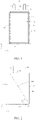
FIG. 1 is an overall schematic structural diagram of an electrochemical device according to an embodiment of this application; -
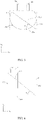
FIG. 2 is a front view of an electrode assembly of the electrochemical device shown inFIG. 1 according to some embodiments; -
FIG. 3 is a front view of an electrode assembly of the electrochemical device shown inFIG. 1 according to some other embodiments; -
FIG. 4 is a front view of an electrode assembly of the electrochemical device shown inFIG. 1 according to still other embodiments; -
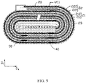
FIG. 5 is a top view of the electrode assembly shown inFIG. 2 according to some embodiments; -
FIG. 6 is a top view of the electrode assembly shown inFIG. 2 according to some other embodiments; -
FIG. 7 is a sectional view of the electrode assembly shown inFIG. 5 and sectioned along a VII-VII line; -
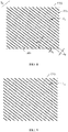
FIG. 8 is a front view of a separator of the electrode assembly shown inFIG. 2 according to some embodiments; -
FIG. 9 is a front view of a separator of the electrode assembly shown inFIG. 2 according to some other embodiments; -
FIG. 10 is a rear view of a separator of the electrode assembly shown inFIG. 2 ; and -
FIG. 11 is a schematic structural diagram of an electronic device according to an embodiment of this application. - This application is further described below with reference to the following specific embodiments and the foregoing drawings.
- The following describes the technical solutions in the embodiments of this application clearly and thoroughly with reference to the drawings herein. Evidently, the described embodiments are merely a part of but not all of the embodiments of this application.
- Unless otherwise defined, all technical and scientific terms used herein have the same meanings as usually understood by a person skilled in the technical field of this application. The terms used in the specification of this application herein are merely intended for describing specific embodiments but are not intended to limit this application.
- The following describes some embodiments of this application in detail with reference to drawings. To the extent that no conflict occurs, the following embodiments and the features in the embodiments may be combined with each other.
- An electrochemical device generally includes electrode plates and a separator disposed between adjacent electrode plates. Generally, a separator of high bonding performance is used so that the adjacent electrode plates and the separator are bonded firmly together to ensure high interfacial adhesion between the separator and the electrode plates, and to suppress expansion deformation caused by gassing inside the electrochemical device. However, the separator of high bonding performance makes interstices smaller between the separator and the electrode plate, and makes the electrode plate hardly permeable by the electrolytic solution. Especially, for a wound battery, uneven distribution of the electrolytic solution is more prone to occur at a corner region of the electrode assembly, thereby leading to purple-speck lithium plating during cycles and impairing the cycle performance of the electrochemical device.
- Referring to
FIG. 1 , an embodiment of this application provides anelectrochemical device 100, including ahousing 10, an electrode assembly 20 (shown inFIG. 5 andFIG. 6 ), an electrolytic solution, afirst tab 30 and asecond tab 40. Theelectrode assembly 20 and the electrolytic solution are accommodated in thehousing 10. Theelectrochemical device 100 shown inFIG. 5 andFIG. 6 includes oneelectrode assembly 20. However, understandably, in order to achieve a high-voltage output, theelectrochemical device 100 may include a plurality ofelectrode assemblies 20 connected in series instead, without being limited in this application. - As shown in
FIG. 5 andFIG. 6 , theelectrode assembly 20 includes electrode plates and aseparator 23 disposed between adjacent electrode plates. The electrode plates include afirst electrode plate 21 and asecond electrode plate 22. Theseparator 23 is disposed between thefirst electrode plate 21 and thesecond electrode plate 22. Theseparator 23 is configured to prevent direct contact between thefirst electrode plate 21 and thesecond electrode plate 22, where the direct contact may cause a short circuit. In some embodiments, theelectrode assembly 20 is obtained by winding thefirst electrode plate 21, the separator, and thesecond electrode plate 22. In other words, theelectrode assembly 20 is a wound structure. In some other embodiments, theelectrode assembly 20 may be obtained by stacking thefirst electrode plate 21, the separator, and thesecond electrode plate 22. In other words, theelectrode assembly 20 is a stacked structure. - The
first tab 30 and thesecond tab 40 are electrically connected to theelectrode assembly 20, respectively, and protrude from thehousing 10 to connect to an external component (not shown in the drawing). Specifically, thefirst electrode plate 21 includes a firstcurrent collector 211 and a firstactive material layer 212 disposed on a surface of the firstcurrent collector 211. Thefirst tab 30 is electrically connected to the firstcurrent collector 211. Thesecond electrode plate 22 includes a secondcurrent collector 221 and a second active material layer 222 disposed on a surface of the secondcurrent collector 221. Thesecond tab 40 is electrically connected to the secondcurrent collector 221. In some embodiments, thefirst electrode plate 21 is a positive electrode plate, and thesecond electrode plate 22 is a negative electrode plate. - As shown in
FIG. 1 , thehousing 10 may be a packaging bag obtained by sealing with a sealing film. In other words, theelectrochemical device 100 may be a pouch-type battery. In this case, thehousing 10 includes abody portion 11 and a sealingportion 12. Thebody portion 11 is configured to accommodate theelectrode assembly 20 and the electrolytic solution. The sealingportion 12 is connected to thebody portion 11. Thefirst tab 30 and thesecond tab 40 protrude out of the sealingportion 12. Thebody portion 11 includes atop surface 111, abottom surface 112, anupper surface 113, a lower surface (not shown), a firstlateral surface 114, and a secondlateral surface 115. Thetop surface 111 is opposite to thebottom surface 112. Theupper surface 113 is opposite to the lower surface, and is connected between thetop surface 111 and thebottom surface 112. The firstlateral surface 114 is opposite to the secondlateral surface 115, and is connected between thetop surface 111 and thebottom surface 112. The sealingportion 12 is connected to thetop surface 111. In other embodiments, without being limited to a pouch-type battery, theelectrochemical device 100 may be a steel- or aluminum-shell battery or the like instead. The type of the electrochemical device is not limited in this application. - Referring to
FIG. 7 , theseparator 23 includes aporous substrate 230 and afirst bonding layer 231 disposed on a surface of theporous substrate 230. Thefirst bonding layer 231 bonds with thefirst electrode plate 21. In another embodiment, thefirst bonding layer 231 may bond with thesecond electrode plate 22 instead. - Referring to
FIG. 8 , thefirst bonding layer 231 includes a plurality offirst bonding regions 2311 spaced apart from each other. In other words, adjacent two of the plurality offirst bonding regions 2311 are interspaced with a gap G1. In some embodiments, the plurality offirst bonding regions 2311 are parallel to each other. Understandably, when two components are referred to as being parallel to each other, the two components are not necessarily parallel to each other exactly, but an angle may exist between the two components, where the angle is -5° to +5°. - It is defined that the thickness direction (that is, the direction from the
upper surface 113 to the lower surface), the length direction (that is, the direction from thebottom surface 112 to the top surface 111), and the width direction (that is, the direction from the firstlateral surface 114 to the second lateral surface 115) of theelectrode assembly 20 are a first direction D1, a third direction D3, and a fourth direction D4, respectively. The third direction D3 is the direction in which thefirst tab 30 and thesecond tab 40 protrude. Referring toFIG. 2 , in some embodiments, in the first direction D1, theprojection 200 of theelectrode assembly 20 is rectangular, and possesses afirst side 201, asecond side 202, and adiagonal line 203 connected to both thefirst side 201 and thesecond side 202. - As shown in
FIG. 2 , theelectrode assembly 20 possesses afirst end portion 20a, asecond end portion 20b, and alateral portion 20c connected between thefirst end portion 20a and thesecond end portion 20b. Thefirst end portion 20a is a head of theelectrode assembly 20, and is a portion at which thefirst tab 30 and thesecond tab 40 are disposed. Thesecond end portion 20b is an ending of theelectrode assembly 20, where the ending is opposite to the head. The projection of thesecond end portion 20b in the first direction D1 forms thefirst side 201. The projection of thelateral portion 20c in the first direction D1 forms thesecond side 202. In this case, the projections of thefirst tab 30 and thesecond tab 40 in the first direction D1 protrude from the opposite side of thefirst side 201, so that thefirst tab 30 and thesecond tab 40 can be electrically connected to an external component conveniently. - Referring to
FIG. 2 andFIG. 8 , it is defined that an angle between thediagonal line 203 and thefirst side 201 is θ1. Thediagonal line 203 of the circumscribed rectangle R tilts against thefirst side 201, and therefore, 0° < θ1 < 90°. The angle between the projection of each of the plurality offirst bonding regions 2311 and thefirst side 201 is θ2. θ1 and θ2 satisfy: θ1/2 ≤ θ2 ≤ (θ1/2 + 45°). - As shown in
FIG. 8 , in some embodiments, eachfirst bonding region 2311 may be strip-shaped and disposed on the surface of theporous substrate 230. That is, each of the plurality offirst bonding regions 2311 is continuous. In this case, the projection of each of the plurality offirst bonding regions 2311 is also strip-shaped. The angle θ2 between the projection of each of the plurality offirst bonding regions 2311 and thefirst side 201 is the angle between the strip-shaped projection and thefirst side 201. As shown inFIG. 9 , in another embodiment, each of the plurality offirst bonding regions 2311 may be discontinuous instead, for example, may be disposed on the surface of theporous substrate 230 in shapes of a plurality of blocks or islands. In this case, the projection of each of the plurality offirst bonding regions 2311 is also in the shape of a plurality of blocks or islands. The angle θ2 between the projection of each of the plurality offirst bonding regions 2311 and thefirst side 201 is the angle between a connection line of the projections of the blocks or islands and thefirst side 201. - Gaps G2 also exist between sections of each discontinuous
first bonding region 2311, and can be used as a channel for transmitting the electrolytic solution, thereby further improving the performance of transmitting the electrolytic solution. - The
first bonding layer 231 disposed on the separator according to this application includes a plurality of spacedfirst bonding regions 2311. The plurality offirst bonding regions 2311 can bond with thefirst electrode plate 21 or thesecond electrode plate 22, so as to improve the interfacial adhesion between theseparator 23 and the electrode plate and suppress the expansion deformation caused by the gassing inside theelectrochemical device 100. This increases the deformation resistance of theelectrochemical device 100, reduces the hazards of deformation and structural disruption of the electrode assembly, and keeps smoothness of the entire conductive network in theelectrode assembly 20, thereby improving the cycle performance of theelectrochemical device 100. A gap G1 exists between adjacent two of the plurality offirst bonding regions 2311 to reserve a space for transmitting the electrolytic solution. After the electrolytic solution is injected, the electrolytic solution can flow through the gap G1 and infiltrate the electrode plate thoroughly, thereby also helping to improve the cycle performance of theelectrochemical device 100. Theelectrochemical device 100 according to this application achieves a trade-off between interfacial adhesion and the required capability of transmitting the electrolytic solution. - Further, in this application, it is set that θ1/2 ≤ θ2 ≤ (θ1/2 + 45°). 0° < θ1 < 90°, and therefore, 0° < θ2 < 90°, thereby causing the projections of the
first bonding regions 2311 to also tilt against thefirst side 201. Therefore, the bonding force of thefirst bonding layer 231 is continuously distributed in the direction of thefirst side 201. That is, the bonding force between theseparator 23 and the electrode plate is continuously distributed in the direction of thefirst side 201, thereby increasing the deformation resistance of theelectrochemical device 100 and improving the cycle performance. In addition, an appropriate relationship is set between θ2 and θ1, and therefore, a tilt angle of thefirst bonding regions 2311 deviates from a tilt angle of thediagonal line 203 of the circumscribed rectangle R by an amount that falls within a specified range. Therefore, eachfirst bonding region 2311 can form a relatively stable triangular fixing relationship with thesecond end portion 20b and thelateral portion 20c of theelectrode assembly 20, thereby further increasing the deformation resistance of theelectrochemical device 100 and improving the cycle performance. - Understandably, in order to improve the competitiveness of electronic devices, some consumer electronic devices are changing toward irregular shapes. An electrochemical device in an irregular shape can make full use of the irregular space in such electronic devices, thereby increasing the capacity of the entire electrochemical device. Therefore, in this application, in the first direction D1, the shape of the
projection 200 of theelectrode assembly 20 is not limited to a rectangle, and may be other irregular shapes instead. As shown inFIG. 3 and FIG. 4 , in another embodiment, when theelectrode assembly 20 is a stacked structure, shapes of theprojection 200 of theelectrode assembly 20 in the first direction D1 include an arc or an L shape. In this case, the circumscribed rectangle R of theprojection 200 of theelectrode assembly 20 also possesses afirst side 201, asecond side 202, and adiagonal line 203 connected between thefirst side 201 and thesecond side 202. Understandably, as shown inFIG. 2 , when theprojection 200 of theelectrode assembly 20 is rectangular, the circumscribed rectangle R of theprojection 200 is theprojection 200 itself. - In some embodiments, the
porous substrate 230 includes a polymer film, a multilayer polymer film, or a non-woven fabric, which, in each case, is formed by at least one of polyolefin, polyvinylidene difluoride, polyethylene terephthalate, cellulose, polyimide, polyamide, spandex, or polyphthalamide. Such polymers possess high thermal stability, and facilitate surface treatment, thereby making it easy to coat theporous substrate 230 with thefirst bonding layer 231. In addition, such polymers are highly flexible and bendable. - The
first bonding layer 231 includes a bonding material. The bonding material includes at least one of the following polymers: poly(vinylidene difluoride-co-hexafluoropropylene), poly(vinylidene difluoride-co-trichloroethylene), polymethyl methacrylate, polyacrylic acid, polyacrylic acid sodium salt, polyacrylonitrile, polyvinylpyrrolidone, polyvinyl acetate, poly(ethylene-co-vinyl acetate), polyimide, polyethylene oxide, cellulose acetate, cellulose acetate butyrate, cellulose acetate propionate, cyanoethyl pullulan, cyanoethyl polyvinyl alcohol, cyanoethyl cellulose, cyanoethyl sucrose, pullulan, sodium carboxymethyl cellulose, lithium carboxymethyl cellulose, poly(acrylonitrile-co-styrene-co-butadiene), polyvinyl alcohol, polyvinyl ether, polytetrafluoroethylene, polyhexafluoropropylene, poly(styrene-co-butadiene), or polyvinylidene difluoride. Such polymers exert a strong bonding effect to bond theseparator 23 and thefirst electrode plate 21 or thesecond electrode plate 22 together. - As shown in
FIG. 7 , in some embodiments, theseparator 23 further includes asecond bonding layer 232. Theporous substrate 230 is located between thefirst bonding layer 231 and thesecond bonding layer 232. When thefirst bonding layer 231 bonds with thefirst electrode plate 21, thesecond bonding layer 232 bonds with thesecond electrode plate 22. Referring toFIG. 10 , thesecond bonding layer 232 includes a plurality ofsecond bonding regions 2321 spaced from each other. In other words, two adjacentsecond bonding regions 2321 are also interspaced with a gap G3 that serves as a channel for transmitting the electrolytic solution. Therefore, thesecond bonding regions 2321 disposed herein further improve the infiltration effect of the electrolytic solution. In some embodiments, a plurality ofsecond bonding regions 2321 are parallel to each other. - In the first direction D1, an angle between the
projection 200 of thesecond bonding regions 2321 and theprojection 200 of thefirst bonding regions 2311 is θ3, where 0° < θ3 < 180°. In other words, thesecond bonding regions 2321 also tilt against thefirst side 201. Therefore, the bonding force of thesecond bonding layer 232 is also continuously distributed in the direction of thefirst side 201, thereby further increasing the deformation resistance of theelectrochemical device 100. - Further, θ2 and θ3 may further satisfy: θ3 = 180° - 2θ2. With the relationship between θ3 and θ2 further defined in this way, the deformation resistance of the
electrode assembly 20 is further increased. - In some embodiments, θ2 = θ1. It is further defined that θ2 is equal to θ1, so that each
first bonding region 2311 can form the stablest triangular fixing relationship with asecond end portion 20b and thelateral portion 20c of theelectrode assembly 20, thereby further increasing the deformation resistance of theelectrode assembly 20. - As shown in
FIG. 8 , in some embodiments, a direction from one of thefirst bonding regions 2311 to another adjacentfirst bonding region 2311 is defined as a second direction D2. In the second direction D2, a width of thefirst bonding region 2311 is d1 mm, a distance between the adjacentfirst bonding regions 2311 is d2 mm, and d1 and d2 satisfy: 0.1 < d1 < 10, and 0.1 < d2 < 10. When d1 is exceptionally small, the bonding force between thefirst bonding layer 231 and the electrode plate is reduced, and the deformation resistance is reduced accordingly. When d1 is exceptionally large, d2 is reduced accordingly on condition that the area of the electrode plate is constant, and the space available for transmitting the electrolytic solution is reduced, thereby deteriorating infiltration of the electrolytic solution. When d2 is exceptionally small, the space available for transmitting the electrolytic solution is also reduced, thereby deteriorating infiltration of the electrolytic solution. When d2 is exceptionally large, d1 is reduced accordingly on condition that the area of the electrode plate is constant, thereby also reducing the bonding force between thefirst bonding layer 231 and the electrode plate and reducing the deformation resistance accordingly. - In some embodiments, d1 and d2 satisfy: 0.1 < d1/d2 < 5. When d1/d2 is exceptionally small, the proportion of the area of the
first bonding regions 2311 is reduced, thereby also reducing the bonding force between thefirst bonding layer 231 and the electrode plate, and reducing the deformation resistance accordingly. When d1/d2 is exceptionally large, the proportion of the area of thefirst bonding regions 2311 is increased, thereby also reducing the space available for transmitting the electrolytic solution and deteriorating infiltration of the electrolytic solution. - In some embodiments, in the first direction D1, a thickness of the
first bonding layer 231 is t1 µm, and 0.15 < t1d1/(d1 + d2) < 2. When t1d1/(d1 + d2) is exceptionally small, the proportion of a diffusion area of thefirst bonding layer 231 softened by heating is reduced, thereby also reducing the bonding force between thefirst bonding layer 231 and the electrode plate, and reducing the deformation resistance accordingly. When t1d1/(d1 + d2) is exceptionally large, the proportion of the diffusion area of thefirst bonding layer 231 softened by heating is increased, thereby also reducing the space available for transmitting the electrolytic solution and deteriorating infiltration of the electrolytic solution. - Referring to
FIG. 7 andFIG. 8 , in some embodiments, 0.1 ≤ t1 ≤ 6. When t1 is exceptionally small, the bonding force between thefirst bonding layer 231 and the electrode plate is reduced. When t1 is exceptionally large, thereby reducing overall air permeability of theseparator 23 and resulting in poor transmission of the electrolytic solution. - In this application, the
electrochemical device 100 may be any type of primary batteries, secondary batteries, fuel cells, solar cells, and capacitors (such as supercapacitors). Especially, the secondary battery may be a lithium secondary battery, including a lithium metal secondary battery, a lithium-ion secondary battery, a lithium polymer secondary battery, and a lithium-ion polymer secondary battery. - Referring to
FIG. 11 , an embodiment of this application further provides anelectronic device 1. Theelectronic device 1 includes theelectrochemical device 100 disclosed above. Theelectronic device 1 according to this application may be, but is not limited to: a notebook computer, a pen-inputting computer, a mobile computer, an e-book player, a portable phone, a portable fax machine, a portable photocopier, a portable printer, a stereo headset, a video recorder, a liquid crystal display television set, a handheld cleaner, a portable CD player, a mini CD-ROM, a transceiver, an electronic notepad, a calculator, a memory card, a portable voice recorder, a radio, a backup power supply, a motor, a car, a motorcycle, a power-assisted bicycle, a bicycle, a lighting appliance, a toy, a game machine, a watch, an electric tool, a flashlight, a camera, a large household battery, a lithium-ion capacitor, and the like. - The following describes this application in detail with reference to specific embodiments and comparative embodiments. This application is described below with reference to a specific preparation process and a test method using a pouch-type cell as an example of the electrochemical device. A person skilled in the art understands that the preparation method described in this application is merely an example. Any other appropriate preparation methods fall within the scope of this application.
- The separator is coated on both sides with a first bonding layer and a second bonding layer. The electrode assembly is obtained by sequentially stacking and winding the first electrode plate, the second electrode plate, and the separator. In the first direction, a projection of the electrode assembly is rectangular. An angle θ1 between a diagonal line of the projection and the first side is 45°. An angle θ2 between a projection of first bonding regions of the first bonding layer and the first side is 90°. An angle θ3 between a projection of second bonding regions of the second bonding layer and the projection of the first bonding regions is 23°. A width d1 of each of the first bonding regions is 0.21 mm, a distance d2 between adjacent first bonding regions is 0.04 mm, and the thickness t1 of the first bonding region is 2 µm.
- The electrode assembly and the electrolytic solution are packaged into an aluminum plastic film to obtain an electrochemical device.
- Differences from
Comparative Embodiment 1 are: the value of θ1, θ2, or θ3 is different; the second bonding layer is omitted in the separator; or, the first bonding layer and the second bonding layer are evenly applied as coating (that is, the entire surface of the porous substrate is evenly coated with the bonding layers). - A capacity retention rate test and a three-point bending test are performed on the electrochemical device in each embodiment and each comparative embodiment, and the corresponding test results are recorded in Table 1. The steps of the capacity retention rate test include: charging the electrochemical device at a constant current of 1 C in a 45 °C muffle oven until the voltage reaches 4.43 V, then charging the electrochemical device at a constant voltage until the current reaches 0.05 C, then leaving the electrochemical device to stand for 5 minutes; and then discharging the electrochemical device at a current of 0.7 C until the voltage reaches 3.0 V, whereupon the discharge capacity is a first-cycle discharge capacity of the electrochemical device, recorded as 100%. The foregoing charging and discharging steps are repeated for 400 cycles separately. A ratio of the discharge capacity of the electrochemical device at the end of the cycles to the first-cycle discharge capacity, multiplied by 100%, is the capacity retention rate.
- The steps of the three-point bending test include: fixing the electrochemical device onto two supporting points that are a distance apart from each other in a dry environment, and using an indenter to apply a pressure to the electrochemical device at a midpoint of the two supporting points; and then recording a displacement by which the electrochemical device is pressed downward with the indenter, and the pressure that is withstood by the electrochemical device and that corresponds to the displacement. When the recorded pressure value jumps (plunges), it indicates that the electrochemical device is fractured inside. The pressure value at this time may be used to represent the hardness of the electrochemical device.
Table 1 θ1 (°) θ2 (°) θ3 (°) 400th-cycle capacity retention rate (%) Three-point bending pressure (N) Comparative Embodiment 145 90 23 67 170 Comparative Embodiment 2 45 90 30 65 167 Comparative Embodiment 3 45 90 45 67 165 Comparative Embodiment 4 45 90 90 68 180 Comparative Embodiment 5 45 Coated evenly Coated evenly 70 190 Embodiment 145 45 23 81 181 Embodiment 2 45 45 30 83 183 Embodiment 3 45 45 45 86 188 Embodiment 4 45 45 90 92 192 Embodiment 5 45 45 120 87 190 Embodiment 6 45 45 160 80 183 Embodiment 7 45 20 140 81 185 Embodiment 8 45 50 80 83 190 Embodiment 9 45 75 30 82 184 Embodiment 1062 45 90 78 181 Embodiment 1162 62 90 88 190 Embodiment 1262 62 56 94 196 - As can be seen from the data in Table 1, compared with
Comparative Embodiments 1 to 4, the electrochemical devices inEmbodiments 1 to 4 possess relatively high hardness (that is, high deformation resistance) and an improved capacity retention rate becauseEmbodiments 1 to 4 satisfy θ1/2 ≤ θ2 ≤ (θ1/2 + 45°). The electrochemical device in Embodiment 4 achieves even a higher deformation resistance and a higher capacity retention rate due to θ2 = θ1. The electrochemical device in Comparative Embodiment 5 achieves the lowest cycle performance because the separator is coated evenly with the bonding layer. - Further, as can be seen from comparison between
Embodiments 1 to 6, when θ1/2 ≤ θ2 ≤ (θ1/2 + 45°), as θ3 increases, the deformation resistance and the capacity retention rate of the electrochemical device show a tendency to increase first and then decrease. When θ3 = 180° - 2θ2, the electrochemical device achieves a higher deformation resistance and a higher capacity retention rate. Therefore, the electrochemical device in Embodiment 4 possesses even a higher deformation resistance and a higher capacity retention rate. - Still further, as can be seen from comparison between Embodiments 4 and 7 to 10, when θ3 = 180° - 2θ2, as θ2 increases, the deformation resistance and the capacity retention rate of the electrochemical device show a tendency to increase first and then decrease. When θ2 = θ1, the electrochemical device achieves even a higher deformation resistance and a higher capacity retention rate. Therefore, the electrochemical device in Embodiment 4 possesses even a higher deformation resistance and a higher capacity retention rate.
- Moreover, when θ2 = θ1, the specific value of θ1 is adjustable. In contrast with
Embodiment 10, the electrochemical devices inEmbodiments 11 to 12 achieve even a higher deformation resistance and a higher capacity retention rate due to θ2 = θ1. - Differences from
Embodiment 1 are that the values of t1, d1, and d2 are further set, and the value of t1, d1, or d2 varies in Embodiments 13 to 26. - A capacity retention rate test and a three-point bending test are performed on the electrochemical device in each embodiment and each comparative embodiment, and the corresponding test results are recorded in Table 2.
Table 2 d1 (mm) d2 (mm) t1 (µm) d1/d2 t1d1/(d1+d2) 400th-cycle capacity retention rate Three-point bending pressure (N) Embodiment 13 0.21 0.04 2 5.250 1.68 70.20 193 Embodiment 14 0.21 0.06 2 3.500 1.56 80.40 189 Embodiment 15 0.21 0.12 2 1.790 1.28 88.40 185 Embodiment 16 0.21 0.31 2 0.679 0.81 85.50 170 Embodiment 170.21 2.20 2 0.095 0.17 84.00 150 Embodiment 18 0.21 12.00 2 0.018 0.03 78.70 130 Embodiment 19 0.52 0.31 2 1.682 1.25 87.40 185 Embodiment 200.83 0.31 2 2.684 1.46 90.40 188 Embodiment 214.02 0.31 2 13.002 1.86 70.20 192 Embodiment 2212.00 12.00 2 1.000 1.00 80.10 167 Embodiment 230.52 0.31 0.5 1.682 0.31 80.20 163 Embodiment 24 0.52 0.31 2.4 1.682 1.51 88.30 181 Embodiment 25 0.52 0.31 5.6 1.682 3.51 75.90 191 Embodiment 26 0.52 0.31 8.2 1.682 5.14 69.90 194 - Under the condition that θ1/2 ≤ θ2 ≤ (θ1/2 + 45°), the value of d2 also affects the capacity retention rate of the electrochemical device. As can be seen from the data in Table 2, in contrast with Embodiments 13 to 17, the bonding force between the separator and the electrode plate in Embodiment 18 is relatively reduced due to d2 greater than 10 mm, thereby relatively reducing the hardness of the electrochemical device (that is, deformation resistance), and also relatively reducing the capacity retention rate.
- Secondly, the value of d1 also affects the capacity retention rate of the electrochemical device. In contrast with Embodiments 16 and 19 to 21, the space available for transmitting the electrolytic solution and the capacity retention rate in
Embodiment 22 are relatively reduced due to d1 greater than 10 mm. - Thirdly, the value of d1/d2 also affects the capacity retention rate of the electrochemical device. In contrast with
Embodiments Embodiment 21 is relatively reduced due to d1/d2 greater than 5. - Finally, the value of t1d1/(d1 + d2) also affects the capacity retention rate of the electrochemical device. In contrast with
Embodiments 19 and 23 to 24, the capacity retention rate of the electrochemical device in Embodiments 25 to 26 is relatively reduced due to t1d1/(d1 + d2) greater than 2. - The foregoing embodiments are merely intended for describing the technical solutions of this application but not intended as a limitation. Although this application is described in detail with reference to the foregoing optional embodiments, a person of ordinary skill in the art understands that modifications or equivalent replacements may be made to the technical solutions of this application.
| |
1 |
| |
10 |
| |
11 |
| |
12 |
| |
20 |
| |
21 |
| |
22 |
| |
23 |
| |
30 |
| |
40 |
| |
100 |
| |
111 |
| |
112 |
| |
113 |
| First |
114 |
| Second |
115 |
| |
200 |
| |
201 |
| |
202 |
| |
203 |
| First |
211 |
| First |
212 |
| Second |
221 |
| Second active material layer | 222 |
| |
230 |
| |
231 |
| |
232 |
| |
2311 |
| |
2321 |
| Circumscribed rectangle | R |
| Gaps | G1, G2, G3 |
| First direction | D1 |
| Second direction | D2 |
| Third direction | D3 |
| Fourth direction | D4 |
| Width | d1 |
| Distance | d2 |
| Thickness | t1 |
Claims (15)
- An electrochemical device, comprising a housing, an electrode assembly and an electrolytic solution, the electrode assembly and the electrolytic solution are disposed in the housing; the electrode assembly comprises electrode plates and a separator disposed between adjacent electrode plates, ;wherein the separator comprises a porous substrate and a first bonding layer disposed on a surface of the porous substrate, and the first bonding layer comprises a plurality of first bonding regions spaced apart from each other; anda thickness direction of the electrode assembly is defined as a first direction; in the first direction, a circumscribed rectangle of a projection of the electrode assembly possesses a diagonal line and a first side, an angle between the diagonal line and the first side is θ1, and an angle between a projection of each of the plurality of first bonding regions and the first side is θ2, wherein θ1/2 ≤ θ2 ≤ (θ1/2 + 45°).
- The electrochemical device according to claim 1, wherein the separator further comprises a second bonding layer, the porous substrate is located between the first bonding layer and the second bonding layer, and the second bonding layer comprises a plurality of second bonding regions spaced apart from each other; and
in the first direction, an angle between a projection of each of the plurality of second bonding regions and the projection of each of the plurality of first bonding regions is θ3, wherein 0° < θ3 < 180°. - The electrochemical device according to claim 2, wherein θ3 = 180° - 2θ2.
- The electrochemical device according to claim 1, wherein θ2 = θ1.
- The electrochemical device according to claim 1, wherein a direction from one of the plurality of first bonding regions to another adjacent one of the plurality of first bonding regions is defined as a second direction, and in the second direction, a width of each of the plurality of first bonding regions is d1 mm, a distance between adjacent two of the plurality of first bonding regions is d2 mm, and d1 and d2 satisfy at least one of the following conditions:0.1 < d1 < 10, and 0.1 < d2 < 10; and0.1 < d1/d2 < 5.
- The electrochemical device according to claim 5, wherein in the first direction, a thickness of the first bonding layer is t1 µm, and 0.15 < t1d1/(d1 + d2) < 2.
- The electrochemical device according to claim 1, wherein in the first direction, a thickness of the first bonding layer is t1 µm, and 0.1 ≤ t1 ≤ 6.
- The electrochemical device according to claim 1, wherein the plurality of the first bonding regions are parallel to each other.
- The electrochemical device according to claim 1, wherein each of the plurality of first bonding regions is continuous or discontinuous.
- The electrochemical device according to claim 1, wherein, in the first direction, shapes of the projection of the electrode assembly comprise a rectangle, an arc, or an L shape.
- The electrochemical device according to claim 1, wherein the electrode assembly further comprises tabs electrically connected to the electrode plates, projections of the tabs in the first direction protrude from an opposite side of the first side.
- The electrochemical device according to claim 1, wherein structures of the electrode assembly comprise a wound structure or a stacked structure.
- The electrochemical device according to claim 1, wherein the porous substrate comprises a polymer film, a multilayer polymer film, or a non-woven fabric, which, in each case, is formed by at least one of polyolefin, polyvinylidene difluoride, polyethylene terephthalate, cellulose, polyimide, polyamide, spandex, or polyphthalamide.
- The electrochemical device according to claim 1, wherein the first bonding layer comprises a bonding material, and the bonding material comprises at least one of poly(vinylidene difluoride-co-hexafluoropropylene), poly(vinylidene difluoride-co-trichloroethylene), polymethyl methacrylate, polyacrylic acid, polyacrylic acid sodium salt, polyacrylonitrile, polyvinylpyrrolidone, polyvinyl acetate, poly(ethylene-co-vinyl acetate), polyimide, polyethylene oxide, cellulose acetate, cellulose acetate butyrate, cellulose acetate propionate, cyanoethyl pullulan, cyanoethyl polyvinyl alcohol, cyanoethyl cellulose, cyanoethyl sucrose, pullulan, sodium carboxymethyl cellulose, lithium carboxymethyl cellulose, poly(acrylonitrile-co-styrene-co-butadiene), polyvinyl alcohol, polyvinyl ether, polytetrafluoroethylene, polyhexafluoropropylene, poly(styrene-co-butadiene), or polyvinylidene difluoride.
- An electronic device, comprising the electrochemical device according to any one of claims 1 to 14.
Applications Claiming Priority (2)
| Application Number | Priority Date | Filing Date | Title |
|---|---|---|---|
| CN202110338853.6A CN115149108B (en) | 2021-03-30 | 2021-03-30 | Electrochemical devices and electronic devices |
| PCT/CN2021/122859 WO2022205829A1 (en) | 2021-03-30 | 2021-10-09 | Electrochemical device and electronic device |
Publications (2)
| Publication Number | Publication Date |
|---|---|
| EP4089824A1 true EP4089824A1 (en) | 2022-11-16 |
| EP4089824A4 EP4089824A4 (en) | 2023-05-10 |
Family
ID=83448383
Family Applications (1)
| Application Number | Title | Priority Date | Filing Date |
|---|---|---|---|
| EP21870476.5A Pending EP4089824A4 (en) | 2021-03-30 | 2021-10-09 | Electrochemical device and electronic device |
Country Status (2)
| Country | Link |
|---|---|
| US (1) | US12412963B2 (en) |
| EP (1) | EP4089824A4 (en) |
Family Cites Families (13)
| Publication number | Priority date | Publication date | Assignee | Title |
|---|---|---|---|---|
| JP3303694B2 (en) | 1996-12-17 | 2002-07-22 | 三菱電機株式会社 | Lithium ion secondary battery and method of manufacturing the same |
| KR101446162B1 (en) | 2011-05-13 | 2014-10-01 | 주식회사 엘지화학 | A separator and electrochemical device containing the same |
| KR101454830B1 (en) | 2012-09-24 | 2014-10-28 | 주식회사 엘지화학 | Method for manufacturing a separator for lithium secondary battery, the separator manufactured by the method and lithium secondary battery including the same |
| CN108598338A (en) | 2017-12-27 | 2018-09-28 | 上海恩捷新材料科技股份有限公司 | A kind of isolation film and the electrochemical appliance comprising the isolation film |
| CN207217641U (en) | 2017-08-18 | 2018-04-10 | 上海恩捷新材料科技股份有限公司 | Lithium ion battery gluing barrier film |
| PL3764449T3 (en) | 2018-02-26 | 2025-05-12 | Zeon Corporation | Method of producing laminate for secondary battery |
| KR102354261B1 (en) | 2018-06-12 | 2022-01-20 | 주식회사 엘지화학 | Separator for electrochemical device, comprising a patterned adhesive layer and a method of manufacturing the separator |
| KR102684621B1 (en) | 2018-09-28 | 2024-07-11 | 주식회사 엘지화학 | Separator for an electrochemical device having a patterned adhesive layer and an electrochemical device comprising the same |
| CN111224047A (en) | 2019-10-17 | 2020-06-02 | 上海恩捷新材料科技有限公司 | Diaphragm and electrochemical device comprising same |
| CN111092192A (en) | 2019-12-27 | 2020-05-01 | 武汉中兴创新材料技术有限公司 | Polymer coating diaphragm and lithium ion battery |
| CN113206350A (en) | 2021-06-07 | 2021-08-03 | 珠海冠宇电池股份有限公司 | Diaphragm and lithium ion battery comprising same |
| CN113410581A (en) | 2021-06-07 | 2021-09-17 | 珠海冠宇电池股份有限公司 | Diaphragm and lithium ion battery comprising same |
| JP7525528B2 (en) * | 2022-01-28 | 2024-07-30 | プライムプラネットエナジー&ソリューションズ株式会社 | Wound electrode body, battery, and method for manufacturing wound electrode body |
-
2021
- 2021-10-09 EP EP21870476.5A patent/EP4089824A4/en active Pending
-
2022
- 2022-03-30 US US17/708,916 patent/US12412963B2/en active Active
Also Published As
| Publication number | Publication date |
|---|---|
| US12412963B2 (en) | 2025-09-09 |
| EP4089824A4 (en) | 2023-05-10 |
| US20220320692A1 (en) | 2022-10-06 |
Similar Documents
| Publication | Publication Date | Title |
|---|---|---|
| EP3907800A1 (en) | Negative electrode sheet, preparation method thereof and lithium ion battery containing the same | |
| CN105393399B (en) | Stack folding-typed electrode assembly | |
| CN100383904C (en) | electrochemical cell stack | |
| US20220336820A1 (en) | Non-aqueous electrolyte secondary battery, collector, and method for manufacturing non-aqueous electrolyte secondary battery | |
| US6805994B1 (en) | Solid electrolyte cell having a rolled electrolyte body | |
| KR101572832B1 (en) | Stepped Electrode Group Stack | |
| US20230140763A1 (en) | Electrochemical device and electronic device containing same | |
| EP3968429A1 (en) | Battery | |
| KR20250160413A (en) | Electrode assembly and battery cell including the same | |
| EP3490051B1 (en) | Electrode assembly comprising electrode lead coupled to long-side area | |
| US12394846B2 (en) | Battery | |
| JP2001325945A (en) | Battery and manufacturing method thereof | |
| US20250141061A1 (en) | Button cell and electronic device | |
| EP4579778A1 (en) | Cylindrical battery cell and cylindrical secondary battery | |
| CN222168431U (en) | Pole piece and battery cell | |
| EP3920305A1 (en) | Electrode assembly, and battery having electrode assembly | |
| JP2002100411A (en) | Battery pack | |
| CN115036587B (en) | Single cells, battery packs and electrical equipment | |
| KR101048690B1 (en) | Lithium-ion Secondary Battery | |
| KR102885254B1 (en) | Electrode assembly and battery cell including the same | |
| US12412963B2 (en) | Electrochemical device and electronic device | |
| WO2022205829A1 (en) | Electrochemical device and electronic device | |
| WO2024227380A1 (en) | Lithium-ion battery and electronic device | |
| KR102892926B1 (en) | Secondary battery and device including the same | |
| KR20160064859A (en) | Convex prismatic shaped can and method for manufacturing prismatic secondary battery comprising same |
Legal Events
| Date | Code | Title | Description |
|---|---|---|---|
| STAA | Information on the status of an ep patent application or granted ep patent |
Free format text: STATUS: UNKNOWN |
|
| STAA | Information on the status of an ep patent application or granted ep patent |
Free format text: STATUS: THE INTERNATIONAL PUBLICATION HAS BEEN MADE |
|
| PUAI | Public reference made under article 153(3) epc to a published international application that has entered the european phase |
Free format text: ORIGINAL CODE: 0009012 |
|
| STAA | Information on the status of an ep patent application or granted ep patent |
Free format text: STATUS: REQUEST FOR EXAMINATION WAS MADE |
|
| 17P | Request for examination filed |
Effective date: 20220328 |
|
| AK | Designated contracting states |
Kind code of ref document: A1 Designated state(s): AL AT BE BG CH CY CZ DE DK EE ES FI FR GB GR HR HU IE IS IT LI LT LU LV MC MK MT NL NO PL PT RO RS SE SI SK SM TR |
|
| A4 | Supplementary search report drawn up and despatched |
Effective date: 20230413 |
|
| RIC1 | Information provided on ipc code assigned before grant |
Ipc: H01M 10/0587 20100101ALN20230405BHEP Ipc: H01M 10/0585 20100101ALN20230405BHEP Ipc: H01M 10/052 20100101ALN20230405BHEP Ipc: H01M 50/489 20210101ALI20230405BHEP Ipc: H01M 50/414 20210101ALI20230405BHEP Ipc: H01M 10/04 20060101ALI20230405BHEP Ipc: H01M 50/40 20210101ALI20230405BHEP Ipc: H01M 50/46 20210101AFI20230405BHEP |
|
| DAV | Request for validation of the european patent (deleted) | ||
| DAX | Request for extension of the european patent (deleted) |