EP4089807A1 - Battery and battery apparatus - Google Patents
Battery and battery apparatus Download PDFInfo
- Publication number
- EP4089807A1 EP4089807A1 EP21185513.5A EP21185513A EP4089807A1 EP 4089807 A1 EP4089807 A1 EP 4089807A1 EP 21185513 A EP21185513 A EP 21185513A EP 4089807 A1 EP4089807 A1 EP 4089807A1
- Authority
- EP
- European Patent Office
- Prior art keywords
- battery
- cell body
- housing
- injecting holes
- connecting plate
- Prior art date
- Legal status (The legal status is an assumption and is not a legal conclusion. Google has not performed a legal analysis and makes no representation as to the accuracy of the status listed.)
- Pending
Links
- 239000007788 liquid Substances 0.000 claims abstract description 113
- 210000005056 cell body Anatomy 0.000 claims abstract description 63
- 210000004027 cell Anatomy 0.000 claims abstract description 37
- 239000003792 electrolyte Substances 0.000 description 20
- 238000002347 injection Methods 0.000 description 14
- 239000007924 injection Substances 0.000 description 14
- 238000000034 method Methods 0.000 description 7
- 230000000694 effects Effects 0.000 description 5
- 230000002349 favourable effect Effects 0.000 description 3
- 238000009736 wetting Methods 0.000 description 3
- 230000006978 adaptation Effects 0.000 description 2
- 238000004026 adhesive bonding Methods 0.000 description 1
- 230000005484 gravity Effects 0.000 description 1
- 238000012986 modification Methods 0.000 description 1
- 230000004048 modification Effects 0.000 description 1
- 238000002360 preparation method Methods 0.000 description 1
- 238000007789 sealing Methods 0.000 description 1
- 238000007493 shaping process Methods 0.000 description 1
- 239000000243 solution Substances 0.000 description 1
- 238000003466 welding Methods 0.000 description 1
Images


Classifications
-
- H—ELECTRICITY
- H01—ELECTRIC ELEMENTS
- H01M—PROCESSES OR MEANS, e.g. BATTERIES, FOR THE DIRECT CONVERSION OF CHEMICAL ENERGY INTO ELECTRICAL ENERGY
- H01M6/00—Primary cells; Manufacture thereof
-
- H—ELECTRICITY
- H01—ELECTRIC ELEMENTS
- H01M—PROCESSES OR MEANS, e.g. BATTERIES, FOR THE DIRECT CONVERSION OF CHEMICAL ENERGY INTO ELECTRICAL ENERGY
- H01M50/00—Constructional details or processes of manufacture of the non-active parts of electrochemical cells other than fuel cells, e.g. hybrid cells
- H01M50/60—Arrangements or processes for filling or topping-up with liquids; Arrangements or processes for draining liquids from casings
- H01M50/609—Arrangements or processes for filling with liquid, e.g. electrolytes
- H01M50/627—Filling ports
-
- H—ELECTRICITY
- H01—ELECTRIC ELEMENTS
- H01M—PROCESSES OR MEANS, e.g. BATTERIES, FOR THE DIRECT CONVERSION OF CHEMICAL ENERGY INTO ELECTRICAL ENERGY
- H01M10/00—Secondary cells; Manufacture thereof
- H01M10/04—Construction or manufacture in general
-
- H—ELECTRICITY
- H01—ELECTRIC ELEMENTS
- H01M—PROCESSES OR MEANS, e.g. BATTERIES, FOR THE DIRECT CONVERSION OF CHEMICAL ENERGY INTO ELECTRICAL ENERGY
- H01M50/00—Constructional details or processes of manufacture of the non-active parts of electrochemical cells other than fuel cells, e.g. hybrid cells
- H01M50/10—Primary casings; Jackets or wrappings
- H01M50/102—Primary casings; Jackets or wrappings characterised by their shape or physical structure
-
- H—ELECTRICITY
- H01—ELECTRIC ELEMENTS
- H01M—PROCESSES OR MEANS, e.g. BATTERIES, FOR THE DIRECT CONVERSION OF CHEMICAL ENERGY INTO ELECTRICAL ENERGY
- H01M50/00—Constructional details or processes of manufacture of the non-active parts of electrochemical cells other than fuel cells, e.g. hybrid cells
- H01M50/10—Primary casings; Jackets or wrappings
- H01M50/147—Lids or covers
- H01M50/148—Lids or covers characterised by their shape
- H01M50/15—Lids or covers characterised by their shape for prismatic or rectangular cells
-
- H—ELECTRICITY
- H01—ELECTRIC ELEMENTS
- H01M—PROCESSES OR MEANS, e.g. BATTERIES, FOR THE DIRECT CONVERSION OF CHEMICAL ENERGY INTO ELECTRICAL ENERGY
- H01M50/00—Constructional details or processes of manufacture of the non-active parts of electrochemical cells other than fuel cells, e.g. hybrid cells
- H01M50/40—Separators; Membranes; Diaphragms; Spacing elements inside cells
- H01M50/471—Spacing elements inside cells other than separators, membranes or diaphragms; Manufacturing processes thereof
- H01M50/474—Spacing elements inside cells other than separators, membranes or diaphragms; Manufacturing processes thereof characterised by their position inside the cells
-
- H—ELECTRICITY
- H01—ELECTRIC ELEMENTS
- H01M—PROCESSES OR MEANS, e.g. BATTERIES, FOR THE DIRECT CONVERSION OF CHEMICAL ENERGY INTO ELECTRICAL ENERGY
- H01M50/00—Constructional details or processes of manufacture of the non-active parts of electrochemical cells other than fuel cells, e.g. hybrid cells
- H01M50/40—Separators; Membranes; Diaphragms; Spacing elements inside cells
- H01M50/471—Spacing elements inside cells other than separators, membranes or diaphragms; Manufacturing processes thereof
- H01M50/477—Spacing elements inside cells other than separators, membranes or diaphragms; Manufacturing processes thereof characterised by their shape
-
- H—ELECTRICITY
- H01—ELECTRIC ELEMENTS
- H01M—PROCESSES OR MEANS, e.g. BATTERIES, FOR THE DIRECT CONVERSION OF CHEMICAL ENERGY INTO ELECTRICAL ENERGY
- H01M50/00—Constructional details or processes of manufacture of the non-active parts of electrochemical cells other than fuel cells, e.g. hybrid cells
- H01M50/50—Current conducting connections for cells or batteries
- H01M50/502—Interconnectors for connecting terminals of adjacent batteries; Interconnectors for connecting cells outside a battery casing
-
- H—ELECTRICITY
- H01—ELECTRIC ELEMENTS
- H01M—PROCESSES OR MEANS, e.g. BATTERIES, FOR THE DIRECT CONVERSION OF CHEMICAL ENERGY INTO ELECTRICAL ENERGY
- H01M50/00—Constructional details or processes of manufacture of the non-active parts of electrochemical cells other than fuel cells, e.g. hybrid cells
- H01M50/10—Primary casings; Jackets or wrappings
- H01M50/102—Primary casings; Jackets or wrappings characterised by their shape or physical structure
- H01M50/103—Primary casings; Jackets or wrappings characterised by their shape or physical structure prismatic or rectangular
-
- H—ELECTRICITY
- H01—ELECTRIC ELEMENTS
- H01M—PROCESSES OR MEANS, e.g. BATTERIES, FOR THE DIRECT CONVERSION OF CHEMICAL ENERGY INTO ELECTRICAL ENERGY
- H01M50/00—Constructional details or processes of manufacture of the non-active parts of electrochemical cells other than fuel cells, e.g. hybrid cells
- H01M50/10—Primary casings; Jackets or wrappings
- H01M50/147—Lids or covers
- H01M50/148—Lids or covers characterised by their shape
-
- H—ELECTRICITY
- H01—ELECTRIC ELEMENTS
- H01M—PROCESSES OR MEANS, e.g. BATTERIES, FOR THE DIRECT CONVERSION OF CHEMICAL ENERGY INTO ELECTRICAL ENERGY
- H01M50/00—Constructional details or processes of manufacture of the non-active parts of electrochemical cells other than fuel cells, e.g. hybrid cells
- H01M50/10—Primary casings; Jackets or wrappings
- H01M50/172—Arrangements of electric connectors penetrating the casing
- H01M50/174—Arrangements of electric connectors penetrating the casing adapted for the shape of the cells
- H01M50/176—Arrangements of electric connectors penetrating the casing adapted for the shape of the cells for prismatic or rectangular cells
-
- H—ELECTRICITY
- H01—ELECTRIC ELEMENTS
- H01M—PROCESSES OR MEANS, e.g. BATTERIES, FOR THE DIRECT CONVERSION OF CHEMICAL ENERGY INTO ELECTRICAL ENERGY
- H01M50/00—Constructional details or processes of manufacture of the non-active parts of electrochemical cells other than fuel cells, e.g. hybrid cells
- H01M50/50—Current conducting connections for cells or batteries
- H01M50/543—Terminals
- H01M50/547—Terminals characterised by the disposition of the terminals on the cells
- H01M50/548—Terminals characterised by the disposition of the terminals on the cells on opposite sides of the cell
-
- H—ELECTRICITY
- H01—ELECTRIC ELEMENTS
- H01M—PROCESSES OR MEANS, e.g. BATTERIES, FOR THE DIRECT CONVERSION OF CHEMICAL ENERGY INTO ELECTRICAL ENERGY
- H01M50/00—Constructional details or processes of manufacture of the non-active parts of electrochemical cells other than fuel cells, e.g. hybrid cells
- H01M50/50—Current conducting connections for cells or batteries
- H01M50/543—Terminals
- H01M50/552—Terminals characterised by their shape
- H01M50/553—Terminals adapted for prismatic, pouch or rectangular cells
- H01M50/557—Plate-shaped terminals
-
- H—ELECTRICITY
- H01—ELECTRIC ELEMENTS
- H01M—PROCESSES OR MEANS, e.g. BATTERIES, FOR THE DIRECT CONVERSION OF CHEMICAL ENERGY INTO ELECTRICAL ENERGY
- H01M50/00—Constructional details or processes of manufacture of the non-active parts of electrochemical cells other than fuel cells, e.g. hybrid cells
- H01M50/60—Arrangements or processes for filling or topping-up with liquids; Arrangements or processes for draining liquids from casings
- H01M50/609—Arrangements or processes for filling with liquid, e.g. electrolytes
- H01M50/618—Pressure control
-
- Y—GENERAL TAGGING OF NEW TECHNOLOGICAL DEVELOPMENTS; GENERAL TAGGING OF CROSS-SECTIONAL TECHNOLOGIES SPANNING OVER SEVERAL SECTIONS OF THE IPC; TECHNICAL SUBJECTS COVERED BY FORMER USPC CROSS-REFERENCE ART COLLECTIONS [XRACs] AND DIGESTS
- Y02—TECHNOLOGIES OR APPLICATIONS FOR MITIGATION OR ADAPTATION AGAINST CLIMATE CHANGE
- Y02E—REDUCTION OF GREENHOUSE GAS [GHG] EMISSIONS, RELATED TO ENERGY GENERATION, TRANSMISSION OR DISTRIBUTION
- Y02E60/00—Enabling technologies; Technologies with a potential or indirect contribution to GHG emissions mitigation
- Y02E60/10—Energy storage using batteries
Definitions
- the disclosure relates to a technical field of batteries, and in particular, to a battery and a battery apparatus.
- a battery includes a housing and a cell.
- the cell is disposed in the housing, and the cell is provided with an anode tab and a cathode tab.
- the anode tab and the cathode tab are connected to the anode and cathode posts on the housing through the electrode connecting sheets.
- Electrolyte injection is an important part in the battery preparation process. At present, liquid injecting holes are usually provided on the housing to complete the liquid injecting process. However, in the related art, when the electrolyte enters the housing through the injecting hole, the electrode sheets of the cell are impacted most of the time, and overall performance of the battery is thus affected.
- a battery is provided, and the battery includes a cell and a housing.
- the cell includes a cell body and tab portions, and each of the tab portions extends from one side of the cell body.
- the cell is disposed in the housing.
- the housing includes a first surface and a second surface opposite to each other, the first surface is provided with liquid injecting holes, and the liquid injecting holes penetrate the first surface and do not penetrate the second surface.
- An orthographic projection of the cell body on the first surface does not overlap the liquid injecting holes.
- a battery apparatus includes the battery described in the first aspect.
- the battery provided by the disclosure includes the cell and the housing.
- the cell includes the cell body and the tab portions.
- the housing is provided with the liquid injecting holes. Further, the orthographic projection of the cell body on the first surface does not overlap the liquid injecting holes. When liquid injection is performed, an electrolyte enters the housing through the liquid injecting holes, and the orthographic projection of the cell body on the first surface and the liquid injecting holes do no overlap.
- connection In particular, a reference to “the” object or “a” and “an” object is intended to denote also one of a possible plurality of such objects.
- the terms “connect”, “fix” should be broadly interpreted, for example, the term “connect” can be “fixedly connect”, “detachably connect”, “integrally connect”, “electrically connect” or “signal connect”.
- the term “connect” also can be “directly connect” or “indirectly connect via a medium”.
- the disclosure aims to provide a battery and a battery apparatus capable of preventing a cell body from being impacted and damaged during liquid injection, and that a good liquid injecting effect is provided, and comprehensive performance of the battery is improved.
- a battery 10 including a cell 200 and a housing 100 is included.
- the cell 200 includes a cell body 210 and tab portions 220, and each of the tab portions 220 extends from one side of the cell body 210.
- the cell 200 is disposed in the housing 100.
- the housing 100 includes a first surface 101 and a second surface 102 opposite to each other.
- the first surface 101 is provided with liquid injecting holes 130, and the liquid injecting holes 130 penetrate the first surface 101 and do not penetrate the second surface 102.
- An orthographic projection of the cell body 210 on the first surface 101 does not overlap the liquid injecting holes 130.
- the battery 10 provided by the disclosure includes the cell 200 and the housing 100.
- the cell 200 includes the cell body 210 and the tab portions 220.
- the housing 100 is provided with the liquid injecting holes 130, and the orthographic projection of the cell body 210 on the first surface 101 does not overlap the liquid injecting holes 130.
- an electrolyte enters the housing 100 through the liquid injecting holes 130. Since the orthographic projection of the cell body 210 on the first surface 101 and the liquid injecting holes 130 do no overlap, the cell body 210 may not be impacted by entry of the electrolyte. As such, the cell body 210 is effectively prevented from being impacted and damaged, a good liquid injecting effect is provided, and comprehensive performance of the battery 10 is improved.
- the battery 10 includes the cell 200 and the housing 100, and the cell 200 is disposed in the housing 100.
- the cell 200 includes the cell body 210 and the tab portions 220, and each of the tab portions 220 extends from one end of the cell body 210.
- the housing 100 includes the first surface 101 and the second surface 102 opposite to each other.
- the first surface 101 is provided with the liquid injecting holes 130, and the liquid injecting holes 130 penetrate the first surface 101 and do not penetrate the second surface 102.
- the orthographic projection of the cell body 210 on the first surface 101 does not overlap the liquid injecting holes 130.
- the housing 100 generally has a cube structure, and a shape and a size of the housing 100 may be set according to actual needs of the battery 10.
- the housing 100 may also be configured to include other structures, such as an electrode post structure including an anode post and a cathode post.
- the first surface 101 may be a bottom surface or a side surface of the housing 100.
- the liquid injecting holes 130 may be disposed on the bottom surface or the side surface of the housing 100, as long as the orthographic projection of the cell body 210 on the first surface 101 and the liquid injecting holes 130 do not overlap.
- the cell 200 is disposed in the housing 100, the cell 200 includes the cell body 210 and the tab portions 220, and each of the tab portions 220 extends from one side of the cell body 210.
- the cell 200 is formed by an anode sheet, a separator, and a cathode sheet stacked in sequence.
- the tab portions 220 include an anode tab portion and a cathode tab portion.
- the anode tab portion is formed on the anode sheet
- the cathode tab portion is formed on the cathode sheet.
- the cell 200 is formed by the anode sheet, the separator, and the cathode sheet stacked in sequence in a zigzag shape.
- each of the tab portions 220 extends from one side of the cell body 210, and a central axis of each of the liquid injecting holes 130 is parallel to a tab portion extending surface 211 of the cell body 210.
- the central axis of each of the liquid injecting holes refers to an axis perpendicular to a plane where the liquid injecting hole 130 is located and passing through a center of the liquid injecting hole 130.
- each of the liquid injecting holes 130 is parallel to the tab portion extending surface 211 of the cell body 210. This means that the impact force generated during liquid injection is also parallel to the tab portion extending surface 211 of the cell body 210.
- the impact force may not directly face a plane where electrode sheets of the cell 200 are located and thus may not impact on and damage the electrode sheets, and in this way, a good liquid injecting effect and a favorable pass rate of the battery 10 are provided.
- an internal space of the housing 100 includes a cell body accommodating zone and tab portion accommodating zones.
- the cell body accommodating zone is configured to accommodates the cell body 210, and the tab portion accommodating zones are configured to accommodate the tab portions 220.
- the housing 100 includes a cell body section 100b and tab portion sections 100a. Each of the tab portion sections 100a is located on one side of the cell body section 100b, and the cell body section 100b surrounds and forms the cell body accommodating zone.
- the tab portion sections 100a surround and form the tab portion accommodating zones, and the liquid injecting holes 130 are disposed on the tab portion sections 100a.
- a number of the tab portion accommodating zones is two, and the tab portion accommodating zones are located on two sides of the cell body accommodating zone.
- the liquid injecting holes 130 are disposed on the tab portion sections 100a corresponding to the tab portion accommodating zones, and the tab portion accommodating zones may provide certain spaces for the electrolyte to make entry during liquid injection, so the electrode sheets may be less affected.
- the liquid injecting holes 130 are disposed at corners of the first surface 101. Junctions of first sides 101 1 and second sides 1012 of the first surface 101 form the corners. In some embodiments, the junctions of the first sides 1011 and the second sides 1012 are approximately right angles, and in some other embodiments, the junctions of the first sides 1011 and the second sides 1012 are rounded.
- the liquid injecting holes 130 are away from central axes of the first sides 1011 and central axes of the second sides 1012 of the first surface 101, and gaps are provided between hole edges of the liquid injecting holes 130 and edges of the first surface 101 forming the corners.
- a length of each of first sides 1011 forming each of the corners is a
- a length of each of second sides 1012 forming each of the corners is b.
- a distance between each of the liquid injecting holes and each of the second sides 1012 is h1
- a distance between each of the liquid injecting holes and each of the first sides 1011 is h2, where a ⁇ b, 1/600a ⁇ h1 ⁇ 1/25a, and 1/100b ⁇ h2 ⁇ 1/5b.
- a value of each of h1 and h2 is 1 mm to 20 mm.
- the corners of the first surface 101 have strong structural strength, so that less deformation may be generated during a process of forming the liquid injecting holes 130.
- the electrolyte may be conveniently injected and sealed after liquid injection.
- a number of the liquid injecting holes 130 is two, and the two liquid injecting holes are diagonally arranged.
- one of the liquid injecting holes 130 is disposed at a first corner of the first surface 101, and the other liquid injecting hole 130 is disposed at a second corner of the first surface 101.
- the first surface and the second surface are diagonally arranged.
- the housing 100 includes the first surface 101 and the second surface 102 opposite to each other and further includes four third surfaces 103 surrounding around the first surface 101 and the second surface 102.
- the first surface 101, the second surface 102, and the third surfaces 103 form the housing 100.
- An area of the first surface 101 is greater than an area of each of the third surfaces 103. That is, the first surface 101 is the large surface of the housing 100, and as the liquid injecting holes 130 are disposed on the large surface of the housing 100 and the large surface may facilitate shaping, process difficulty is thus reduced.
- the housing 100 may substantially exhibit a cuboid structure. When the housing 100 is substantially shaped as a cuboid, the cuboid is flat.
- each of the tab portions 220 includes two or more single tabs 221 extending from a side surface of the cell body 210.
- An overlapping direction of the single tabs 221 is a first direction when the single tabs 221 are flattened in a direction perpendicular to the side surface of the cell body 210.
- the first surface 101 is one of the opposite two surfaces of the housing 100 in the first direction.
- the liquid injecting holes 130 are disposed on the first surface 101. When the electrolyte enters the housing 100 through the liquid injecting holes 130, an injecting direction of the electrolyte is substantially parallel to the first direction.
- the electrolyte injected in this direction may not generate an impact force on a side surface formed by stacking of the single tabs 221, so that damage to the tab portion 220 is thus lowered.
- orthographic projections of the single tabs 221 on the first surface 101 do not overlap the liquid injecting holes 130.
- the injecting direction of the electrolyte is not straight to the single tabs 221 and may not impact on the single tabs 221, so that the tab portions 220 are effectively prevented from being damaged.
- the housing 100 includes a bottom housing 110 and a top cover 120.
- the bottom housing 110 includes a bottom wall and a side wall connected to the bottom wall, and the bottom housing and the side wall form a hollow structure with a top opening.
- the top cover 120 is hermetically connected to the top opening of the bottom housing 110.
- the bottom wall of the bottom housing 110 forms the first surface 101 of the housing 100, and an area of the bottom wall is greater than that of the side wall.
- a top wall of the top cover 120 forms the second surface 102 of the housing 100.
- the top cover 120 and the bottom housing 110 may be connected by welding or gluing, which is not particularly limited by the disclosure. Note that the housing 100 may also have other structures.
- the housing 100 may also exhibit a cuboid structure including a bottom housing and a side cover.
- the bottom housing is a space structure having a side end opening, a bottom wall and a top wall of the bottom housing is the first surface 101 and the second surface 102 of the housing 100, and the side cover is connected to the side end opening of the bottom housing.
- the housing 100 includes the bottom housing 110 and the top cover 120. In such a structural housing 100, the cell 200 may be conveniently assembled, and the cell 200 may not be easily damaged during the assembly process.
- the battery 10 further includes holders 300.
- the holders 300 are disposed in the housing 100, and each of the holders 300 are located on one side of the cell body 210.
- the holders support between the first surface 101 and the second surface 102 of the housing 100 and are located between an end side surface of the housing 100 and the tab portion extending surface 211 of the cell body 210.
- a number of the holders 300 is two, and the holders 300 are located on two sides of the cell body 210.
- the two holders 300 stably secure the cell body 210 in the housing 100.
- the holders 300 support between the first surface 101 and the second surface 102 of the housing 100.
- partial surfaces of the holders 300 abut between the first surface 101 and the second surface 102 of the housing 100 to support the housing 100 and to maintain stability of the first surface 101 and the second surface 102.
- each of the holders 300 is provided with a liquid inlet hole 331 and a liquid inlet channel 320, and a projection of the liquid inlet hole 331 on the first surface 101 at least partially overlaps the liquid injecting hole 130.
- a portion of the holder 300 provided with the liquid inlet hole 331 abuts against the first surface 101, and one end of the liquid inlet channel 320 communicates with the liquid inlet hole 331.
- the electrolyte may directly enter the cell 200 through the liquid inlet channel 320 after passing through the liquid injecting hole 130 and the liquid inlet hole 331. A portion of the holder 300 provided with the liquid inlet hole 331 abuts against the first surface 101. In this way, deformation of the housing 100 which may affect sealing of the battery during the liquid injection process is prevented from occurring, and liquid splitting is also prevented from occurring before the electrolyte enters the liquid inlet hole 331, as such, the electrolyte may smoothly enter the cell 200 and wets the electrode sheets of the cell 200.
- the liquid inlet channel 320 is provided with a flow guide 370.
- the flow guide 370 is configured to guide the electrolyte when liquid injection is performed, so that the electrolyte may smoothly wet the electrode sheets of the cell, liquid injecting may be sped up, and a favorable wetting effect is provided.
- the holder 300 includes a first connecting plate 330, a second connecting plate 340, and supports 350.
- the liquid inlet hole 331 is disposed on the first connecting plate 330.
- the second connecting plate 340 and the first connecting plate 330 are opposite to each other.
- a structure of the supports 350 is not limited by the disclosure, for example, the supports 350 may be column-shaped or plate-shaped.
- the supports 350 have a plate-shaped structure, and a number of the supports 350 is multiple. The multiple supports 350 are arranged at intervals and are connected between the first connecting plate 330 and the second connecting plate 340.
- the second connecting plate 340 includes a tab portion accommodating section 342 and support sections 341 located at two ends of the tab portion accommodating section 342.
- the tab portion accommodating section 342 is recessed towards the first connecting plate 330 and forms a tab portion yielding zone 310.
- the tab portion yielding zone 310 is configured to accommodate the tab portion.
- the support sections 341 are configured to support the first surface 101 and the second surface 102 of the housing 100.
- An orthographic projection of the liquid inlet hole 331 on the second connecting plate 340 is located on the support sections 341.
- the flow guide 370 is connected between the first connecting plate 330 and the second connecting plate 340.
- An orthographic projection of the flow guide 370 on the first connecting plate 330 at least partially overlaps the liquid inlet hole 331, so that the electrolyte may enter the cell body 210 along the flow guide 370 after entering the liquid inlet hole 331.
- the orthographic projection of the flow guide 370 on the first connecting plate 330 at least partially overlaps the liquid inlet hole 331, the impact force generated by the electrolyte may be reduced, and the electrode sheets of the cell may be further prevented from being damaged.
- the flow guide 370 includes a flow guide surface 372, and one end of the flow guide surface 372 close to the second connecting plate 340 is inclined towards the cell body 210. In this way, the electrolyte flows towards the cell body 210 under action of gravity of its own and the impact force generated by liquid injection to complete the wetting of the cell 200 and the entire liquid injection process.
- the flow guide 370 is connected between the adjacent two supports 350, and the orthographic projection of the flow guide 370 on the first connecting plate 330 covers the liquid inlet hole 331.
- the flow guide 370 may be connected between the adjacent two supports 350 in a horizontal state and may also be connected between the adjacent two supports 350 in an inclined state, and connection state is not particularly limited by the disclosure.
- a shape of the flow guide 370 may also be configured according to actual needs, and in a specific embodiment, the flow guide 370 is a flat plate, and one side surface of the flow guide 370 close to the liquid inlet hole is the flow guide surface 372.
- the flow guide 370 is connected between the first connecting plate 330 and the second connecting plate 340.
- the flow guide 370 has the flow guide surface 372.
- One end of the flow guide surface 372 is connected to the first connecting plate 330, and the other end is connected to the second connecting plate 340.
- the one end of the flow guide surface 372 connected to the second connecting plate 340 is inclined towards the cell body 210.
- the flow guide 370 further includes a first connecting surface and a second connecting surface 371.
- the first connecting surface is connected to the first connecting plate 330, and the second connecting surface 371 is connected to the second connecting plate 340.
- the first connecting surface and the second connecting surface 371 are opposite to each other, and the flow guide surface 372 is connected to the first connecting surface and an end portion of the second connecting surface 371.
- the flow guide surface 372 is an inclined surface, and in some other specific embodiments, the flow guide surface 372 is a smoothly curved surface.
- the first surface 101 and the second surface 102 of the housing 100 are opposite to each other.
- the first surface 101 is provided with first grooves 140, and the liquid injecting holes 130 are not located in the first grooves 140.
- the first connecting plate 330 is provided with a second groove 332 matching a shape and size of the corresponding first groove 140.
- the first grooves 140 may be configured to accommodate related components (e.g., electrode posts) on the housing 100 of the adjacent battery 10.
- the second grooves 332 are configured to be matched with the first grooves 140 to provide spaces for accommodating the electrode posts.
- the first connecting plate 330 includes a first section 333 and a second section 334.
- the liquid inlet hole 331 is disposed on the first section 333, and the second section 334 is recessed to form the second groove 332.
- the disclosure further provides a battery apparatus including at least two of the batteries 10 described in any one of the foregoing embodiments.
- the battery apparatus may be a battery module or a battery pack.
- the battery module includes a plurality of batteries 10, end plates, and side plates. The end plates and the side plates are configured to secure the batteries 10.
- the battery pack includes a plurality of batteries 10 and a battery box, and the battery box is configured to secure the batteries 10.
Landscapes
- Chemical & Material Sciences (AREA)
- Chemical Kinetics & Catalysis (AREA)
- Electrochemistry (AREA)
- General Chemical & Material Sciences (AREA)
- Engineering & Computer Science (AREA)
- Manufacturing & Machinery (AREA)
- Filling, Topping-Up Batteries (AREA)
- Battery Mounting, Suspending (AREA)
Abstract
The disclosure relates to a technical field of batteries, and a battery (10) and a battery apparatus are provided. The battery (10) includes a cell (200), and the cell (200) includes a cell body (210) and tab portions (220). Each of the tab portions (220) extends from one side of the cell body (210). The battery (10) further includes a housing (100). The housing (100) is a hollow structure, and the hollow structure is formed inside the housing (100). The cell (200) is disposed in the housing (100), and the housing (100) includes a first surface (101) and a second surface (102) opposite to each other. The first surface (101) is provided with liquid injecting holes (130), and the liquid injecting holes (130) penetrate the first surface (101) and do not penetrate the second surface (102). An orthographic projection of the cell body (210) on the first surface (101) does not overlap the liquid injecting holes (130).
Description
- The disclosure relates to a technical field of batteries, and in particular, to a battery and a battery apparatus.
- A battery includes a housing and a cell. The cell is disposed in the housing, and the cell is provided with an anode tab and a cathode tab. The anode tab and the cathode tab are connected to the anode and cathode posts on the housing through the electrode connecting sheets. Electrolyte injection is an important part in the battery preparation process. At present, liquid injecting holes are usually provided on the housing to complete the liquid injecting process. However, in the related art, when the electrolyte enters the housing through the injecting hole, the electrode sheets of the cell are impacted most of the time, and overall performance of the battery is thus affected.
- The above-mentioned information disclosed in the BACKGROUND section is only used to strengthen the understanding of the background of the disclosure, and therefore it may include information that does not constitute the prior art known to a person having ordinary skill in the art.
- According to the first aspect of the disclosure, a battery is provided, and the battery includes a cell and a housing.
- The cell includes a cell body and tab portions, and each of the tab portions extends from one side of the cell body.
- The cell is disposed in the housing. The housing includes a first surface and a second surface opposite to each other, the first surface is provided with liquid injecting holes, and the liquid injecting holes penetrate the first surface and do not penetrate the second surface. An orthographic projection of the cell body on the first surface does not overlap the liquid injecting holes.
- According to the second aspect of the disclosure, a battery apparatus is provided, and the battery apparatus includes the battery described in the first aspect.
- The battery provided by the disclosure includes the cell and the housing. The cell includes the cell body and the tab portions. The housing is provided with the liquid injecting holes. Further, the orthographic projection of the cell body on the first surface does not overlap the liquid injecting holes. When liquid injection is performed, an electrolyte enters the housing through the liquid injecting holes, and the orthographic projection of the cell body on the first surface and the liquid injecting holes do no overlap.
- For a better understanding of the disclosure, reference may be made to exemplary embodiments shown in the following drawings. The components in the drawings are not necessarily to scale and related elements may be omitted, or in some instances proportions may have been exaggerated, so as to emphasize and clearly illustrate the features described herein. In addition, related elements or components can be variously arranged, as known in the art. Further, in the drawings, like reference numerals designate same or like parts throughout the several views.
-
FIG. 1 is an exploded view of a battery according to an exemplary embodiment of the disclosure. -
FIG. 2 is a schematic view of a structure of arrangement of a cell in a housing according to an exemplary embodiment of the disclosure. -
FIG. 3 is a top view ofFIG. 2 . -
FIG. 4 is a schematic view of a structure of the housing according to an exemplary embodiment of the disclosure. -
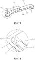
FIG. 5 is a schematic view of a structure of a holder according to an exemplary embodiment of the disclosure. -
FIG. 6 is a schematic view of the structure of the holder according to another exemplary embodiment of the disclosure. -
FIG. 7 is a schematic view of the structure of the holder according to still another exemplary embodiment of the disclosure. -
FIG. 8 is an enlargement view of portion A inFIG. 2 . -
FIG. 9 is an enlargement view of portion B inFIG. 5 . -
FIG. 10 is an enlargement view of portion C inFIG. 6 . -
FIG. 11 is an enlargement view of portion D inFIG. 7 . -
FIG. 12 is a schematic view of a structure of extension of tab portions from a cell body according to an exemplary embodiment of the disclosure. -
FIG. 13 is a planar graph of a first surface in the housing according to an exemplary embodiment of the disclosure. -
FIG. 14 is a schematic view of a structure of a battery apparatus according to an exemplary embodiment of the disclosure. - The technical solutions in the exemplary embodiments of the disclosure will be described clearly and explicitly in conjunction with the drawings in the exemplary embodiments of the disclosure. The description proposed herein is just the exemplary embodiments for the purpose of illustrations only, not intended to limit the scope of the disclosure, so it should be understood that and various modifications and variations could be made thereto without departing from the scope of the disclosure.
- In the description of the present disclosure, unless otherwise specifically defined and limited, the terms "first", "second" and the like are only used for illustrative purposes and are not to be construed as expressing or implying a relative importance. The term "plurality" is two or more. The term "and/or" includes any and all combinations of one or more of the associated listed items.
- In particular, a reference to "the" object or "a" and "an" object is intended to denote also one of a possible plurality of such objects. Unless otherwise defined or described, the terms "connect", "fix" should be broadly interpreted, for example, the term "connect" can be "fixedly connect", "detachably connect", "integrally connect", "electrically connect" or "signal connect". The term "connect" also can be "directly connect" or "indirectly connect via a medium". For the persons skilled in the art, the specific meanings of the abovementioned terms in the present disclosure can be understood according to the specific situation.
- Further, in the description of the present disclosure, it should be understood that spatially relative terms, such as "above", "below" "inside", "outside" and the like, are described based on orientations illustrated in the figures, but are not intended to limit the exemplary embodiments of the present disclosure.
- In the context, it should also be understood that when an element or features is provided "outside" or "inside" of another element(s), it can be directly provided "outside" or "inside" of the other element, or be indirectly provided "outside" or "inside" of the another element(s) by an intermediate element.
- The disclosure aims to provide a battery and a battery apparatus capable of preventing a cell body from being impacted and damaged during liquid injection, and that a good liquid injecting effect is provided, and comprehensive performance of the battery is improved.
- As shown in
FIG. 1 , in the embodiments of the disclosure, abattery 10 including acell 200 and ahousing 100 is included. Thecell 200 includes acell body 210 andtab portions 220, and each of thetab portions 220 extends from one side of thecell body 210. Thecell 200 is disposed in thehousing 100. Thehousing 100 includes afirst surface 101 and asecond surface 102 opposite to each other. Thefirst surface 101 is provided with liquid injectingholes 130, and theliquid injecting holes 130 penetrate thefirst surface 101 and do not penetrate thesecond surface 102. An orthographic projection of thecell body 210 on thefirst surface 101 does not overlap the liquid injectingholes 130. - The
battery 10 provided by the disclosure includes thecell 200 and thehousing 100. Thecell 200 includes thecell body 210 and thetab portions 220. Thehousing 100 is provided with theliquid injecting holes 130, and the orthographic projection of thecell body 210 on thefirst surface 101 does not overlap the liquid injectingholes 130. When liquid injection is performed, an electrolyte enters thehousing 100 through the liquid injectingholes 130. Since the orthographic projection of thecell body 210 on thefirst surface 101 and theliquid injecting holes 130 do no overlap, thecell body 210 may not be impacted by entry of the electrolyte. As such, thecell body 210 is effectively prevented from being impacted and damaged, a good liquid injecting effect is provided, and comprehensive performance of thebattery 10 is improved. - Components of the
battery 10 provided by the embodiments of the disclosure are described in detail in combination with accompanying drawings. - As shown in
FIG. 1 to FIG. 3 , thebattery 10 includes thecell 200 and thehousing 100, and thecell 200 is disposed in thehousing 100. Herein, thecell 200 includes thecell body 210 and thetab portions 220, and each of thetab portions 220 extends from one end of thecell body 210. Thehousing 100 includes thefirst surface 101 and thesecond surface 102 opposite to each other. Thefirst surface 101 is provided with theliquid injecting holes 130, and theliquid injecting holes 130 penetrate thefirst surface 101 and do not penetrate thesecond surface 102. The orthographic projection of thecell body 210 on thefirst surface 101 does not overlap the liquid injecting holes 130. - In some embodiments of the disclosure, the
housing 100 generally has a cube structure, and a shape and a size of thehousing 100 may be set according to actual needs of thebattery 10. In addition, thehousing 100 may also be configured to include other structures, such as an electrode post structure including an anode post and a cathode post. Thefirst surface 101 may be a bottom surface or a side surface of thehousing 100. Theliquid injecting holes 130 may be disposed on the bottom surface or the side surface of thehousing 100, as long as the orthographic projection of thecell body 210 on thefirst surface 101 and theliquid injecting holes 130 do not overlap. - In some embodiments of the disclosure, the
cell 200 is disposed in thehousing 100, thecell 200 includes thecell body 210 and thetab portions 220, and each of thetab portions 220 extends from one side of thecell body 210. Thecell 200 is formed by an anode sheet, a separator, and a cathode sheet stacked in sequence. Thetab portions 220 include an anode tab portion and a cathode tab portion. The anode tab portion is formed on the anode sheet, and the cathode tab portion is formed on the cathode sheet. In a preferred embodiment, thecell 200 is formed by the anode sheet, the separator, and the cathode sheet stacked in sequence in a zigzag shape. - In some embodiments of the disclosure as shown in
FIG. 2 ,FIG. 3 , andFIG. 8 , each of thetab portions 220 extends from one side of thecell body 210, and a central axis of each of theliquid injecting holes 130 is parallel to a tabportion extending surface 211 of thecell body 210. In the disclosure, the central axis of each of the liquid injecting holes refers to an axis perpendicular to a plane where theliquid injecting hole 130 is located and passing through a center of theliquid injecting hole 130. When liquid injection is performed, the electrolyte generally generates a certain impact force in a direction of the central axis of theliquid injecting hole 130. In the disclosure, the central axis of each of theliquid injecting holes 130 is parallel to the tabportion extending surface 211 of thecell body 210. This means that the impact force generated during liquid injection is also parallel to the tabportion extending surface 211 of thecell body 210. The impact force may not directly face a plane where electrode sheets of thecell 200 are located and thus may not impact on and damage the electrode sheets, and in this way, a good liquid injecting effect and a favorable pass rate of thebattery 10 are provided. - As shown in
FIG. 1 andFIG. 4 , in some embodiments of the disclosure, an internal space of thehousing 100 includes a cell body accommodating zone and tab portion accommodating zones. The cell body accommodating zone is configured to accommodates thecell body 210, and the tab portion accommodating zones are configured to accommodate thetab portions 220. Thehousing 100 includes acell body section 100b andtab portion sections 100a. Each of thetab portion sections 100a is located on one side of thecell body section 100b, and thecell body section 100b surrounds and forms the cell body accommodating zone. Thetab portion sections 100a surround and form the tab portion accommodating zones, and theliquid injecting holes 130 are disposed on thetab portion sections 100a. In some embodiments, a number of the tab portion accommodating zones is two, and the tab portion accommodating zones are located on two sides of the cell body accommodating zone. Theliquid injecting holes 130 are disposed on thetab portion sections 100a corresponding to the tab portion accommodating zones, and the tab portion accommodating zones may provide certain spaces for the electrolyte to make entry during liquid injection, so the electrode sheets may be less affected. - As shown in
FIG. 1 ,FIG. 3 ,FIG. 4 , andFIG. 13 , in some embodiments of the disclosure, theliquid injecting holes 130 are disposed at corners of thefirst surface 101. Junctions offirst sides 101 1 andsecond sides 1012 of thefirst surface 101 form the corners. In some embodiments, the junctions of thefirst sides 1011 and thesecond sides 1012 are approximately right angles, and in some other embodiments, the junctions of thefirst sides 1011 and thesecond sides 1012 are rounded. Theliquid injecting holes 130 are away from central axes of thefirst sides 1011 and central axes of thesecond sides 1012 of thefirst surface 101, and gaps are provided between hole edges of theliquid injecting holes 130 and edges of thefirst surface 101 forming the corners. To be specific, a length of each offirst sides 1011 forming each of the corners is a, and a length of each ofsecond sides 1012 forming each of the corners is b. A distance between each of the liquid injecting holes and each of thesecond sides 1012 is h1, and a distance between each of the liquid injecting holes and each of thefirst sides 1011 is h2, where a ≥ b, 1/600a ≤ h1 ≤ 1/25a, and 1/100b ≤ h2 ≤ 1/5b. In some specific embodiments, a value of each of h1 and h2 is 1 mm to 20 mm. The corners of thefirst surface 101 have strong structural strength, so that less deformation may be generated during a process of forming the liquid injecting holes 130. In addition, in a liquid injecting process, the electrolyte may be conveniently injected and sealed after liquid injection. - In some embodiments of the disclosure, a number of the
liquid injecting holes 130 is two, and the two liquid injecting holes are diagonally arranged. To be specific, one of theliquid injecting holes 130 is disposed at a first corner of thefirst surface 101, and the otherliquid injecting hole 130 is disposed at a second corner of thefirst surface 101. The first surface and the second surface are diagonally arranged. In the disclosure, with the diagonal arrangement of the two liquid injectingholes 130, on the one hand, liquid injection efficiency is improved, and on the other hand, a favorable wetting effect is provided by the electrode sheets of the cell. - As shown in
FIG. 1 andFIG. 4 , in some embodiments of the disclosure, thehousing 100 includes thefirst surface 101 and thesecond surface 102 opposite to each other and further includes fourthird surfaces 103 surrounding around thefirst surface 101 and thesecond surface 102. Thefirst surface 101, thesecond surface 102, and thethird surfaces 103 form thehousing 100. An area of thefirst surface 101 is greater than an area of each of the third surfaces 103. That is, thefirst surface 101 is the large surface of thehousing 100, and as theliquid injecting holes 130 are disposed on the large surface of thehousing 100 and the large surface may facilitate shaping, process difficulty is thus reduced. Preferably, thehousing 100 may substantially exhibit a cuboid structure. When thehousing 100 is substantially shaped as a cuboid, the cuboid is flat. - As shown in
FIG. 1 andFIG. 12 , in some embodiments, each of thetab portions 220 includes two or moresingle tabs 221 extending from a side surface of thecell body 210. An overlapping direction of thesingle tabs 221 is a first direction when thesingle tabs 221 are flattened in a direction perpendicular to the side surface of thecell body 210. Thefirst surface 101 is one of the opposite two surfaces of thehousing 100 in the first direction. In this embodiment, theliquid injecting holes 130 are disposed on thefirst surface 101. When the electrolyte enters thehousing 100 through theliquid injecting holes 130, an injecting direction of the electrolyte is substantially parallel to the first direction. The electrolyte injected in this direction may not generate an impact force on a side surface formed by stacking of thesingle tabs 221, so that damage to thetab portion 220 is thus lowered. In a preferred embodiment, orthographic projections of thesingle tabs 221 on thefirst surface 101 do not overlap the liquid injecting holes 130. In the embodiment, the injecting direction of the electrolyte is not straight to thesingle tabs 221 and may not impact on thesingle tabs 221, so that thetab portions 220 are effectively prevented from being damaged. - In some specific embodiments, the
housing 100 includes abottom housing 110 and atop cover 120. Thebottom housing 110 includes a bottom wall and a side wall connected to the bottom wall, and the bottom housing and the side wall form a hollow structure with a top opening. Thetop cover 120 is hermetically connected to the top opening of thebottom housing 110. The bottom wall of thebottom housing 110 forms thefirst surface 101 of thehousing 100, and an area of the bottom wall is greater than that of the side wall. A top wall of thetop cover 120 forms thesecond surface 102 of thehousing 100. Thetop cover 120 and thebottom housing 110 may be connected by welding or gluing, which is not particularly limited by the disclosure. Note that thehousing 100 may also have other structures. For instance, thehousing 100 may also exhibit a cuboid structure including a bottom housing and a side cover. The bottom housing is a space structure having a side end opening, a bottom wall and a top wall of the bottom housing is thefirst surface 101 and thesecond surface 102 of thehousing 100, and the side cover is connected to the side end opening of the bottom housing. In a preferred embodiment, thehousing 100 includes thebottom housing 110 and thetop cover 120. In such astructural housing 100, thecell 200 may be conveniently assembled, and thecell 200 may not be easily damaged during the assembly process. - As shown in
FIG. 1 , in some embodiments of the disclosure, thebattery 10 further includesholders 300. Theholders 300 are disposed in thehousing 100, and each of theholders 300 are located on one side of thecell body 210. The holders support between thefirst surface 101 and thesecond surface 102 of thehousing 100 and are located between an end side surface of thehousing 100 and the tabportion extending surface 211 of thecell body 210. In some embodiments of the disclosure, a number of theholders 300 is two, and theholders 300 are located on two sides of thecell body 210. The twoholders 300 stably secure thecell body 210 in thehousing 100. Theholders 300 support between thefirst surface 101 and thesecond surface 102 of thehousing 100. In some specific embodiments, partial surfaces of theholders 300 abut between thefirst surface 101 and thesecond surface 102 of thehousing 100 to support thehousing 100 and to maintain stability of thefirst surface 101 and thesecond surface 102. - As shown in
FIG. 5 to FIG. 7 andFIG. 9 to FIG. 11 , in some embodiments of the disclosure, each of theholders 300 is provided with aliquid inlet hole 331 and aliquid inlet channel 320, and a projection of theliquid inlet hole 331 on thefirst surface 101 at least partially overlaps theliquid injecting hole 130. A portion of theholder 300 provided with theliquid inlet hole 331 abuts against thefirst surface 101, and one end of theliquid inlet channel 320 communicates with theliquid inlet hole 331. When liquid injection is performed, a liquid injecting nozzle of a liquid injecting device is required to be inserted into the liquid injecting hole to be in close contact with thehousing 100. The electrolyte may directly enter thecell 200 through theliquid inlet channel 320 after passing through theliquid injecting hole 130 and theliquid inlet hole 331. A portion of theholder 300 provided with theliquid inlet hole 331 abuts against thefirst surface 101. In this way, deformation of thehousing 100 which may affect sealing of the battery during the liquid injection process is prevented from occurring, and liquid splitting is also prevented from occurring before the electrolyte enters theliquid inlet hole 331, as such, the electrolyte may smoothly enter thecell 200 and wets the electrode sheets of thecell 200. - As shown in
FIG. 9 to FIG. 11 , in some embodiments of the disclosure, theliquid inlet channel 320 is provided with aflow guide 370. Theflow guide 370 is configured to guide the electrolyte when liquid injection is performed, so that the electrolyte may smoothly wet the electrode sheets of the cell, liquid injecting may be sped up, and a favorable wetting effect is provided. - As shown in
FIG. 5 to FIG. 7 , in some embodiments of the disclosure, theholder 300 includes a first connectingplate 330, a second connectingplate 340, and supports 350. Theliquid inlet hole 331 is disposed on the first connectingplate 330. The second connectingplate 340 and the first connectingplate 330 are opposite to each other. Note that a structure of thesupports 350 is not limited by the disclosure, for example, thesupports 350 may be column-shaped or plate-shaped. In some specific embodiments of the disclosure, thesupports 350 have a plate-shaped structure, and a number of thesupports 350 is multiple. Themultiple supports 350 are arranged at intervals and are connected between the first connectingplate 330 and the second connectingplate 340. - In some embodiments, the second connecting
plate 340 includes a tabportion accommodating section 342 andsupport sections 341 located at two ends of the tabportion accommodating section 342. The tabportion accommodating section 342 is recessed towards the first connectingplate 330 and forms a tabportion yielding zone 310. The tabportion yielding zone 310 is configured to accommodate the tab portion. Thesupport sections 341 are configured to support thefirst surface 101 and thesecond surface 102 of thehousing 100. An orthographic projection of theliquid inlet hole 331 on the second connectingplate 340 is located on thesupport sections 341. - As shown in
FIG. 9 to FIG. 11 , in some embodiments of the disclosure, theflow guide 370 is connected between the first connectingplate 330 and the second connectingplate 340. An orthographic projection of theflow guide 370 on the first connectingplate 330 at least partially overlaps theliquid inlet hole 331, so that the electrolyte may enter thecell body 210 along theflow guide 370 after entering theliquid inlet hole 331. In addition, as the orthographic projection of theflow guide 370 on the first connectingplate 330 at least partially overlaps theliquid inlet hole 331, the impact force generated by the electrolyte may be reduced, and the electrode sheets of the cell may be further prevented from being damaged. - As shown in
FIG. 10 andFIG. 11 , in some embodiments of the disclosure, theflow guide 370 includes aflow guide surface 372, and one end of theflow guide surface 372 close to the second connectingplate 340 is inclined towards thecell body 210. In this way, the electrolyte flows towards thecell body 210 under action of gravity of its own and the impact force generated by liquid injection to complete the wetting of thecell 200 and the entire liquid injection process. - As shown in
FIG. 5 andFIG. 9 , in some other embodiments of the disclosure, theflow guide 370 is connected between the adjacent twosupports 350, and the orthographic projection of theflow guide 370 on the first connectingplate 330 covers theliquid inlet hole 331. Note that theflow guide 370 may be connected between the adjacent twosupports 350 in a horizontal state and may also be connected between the adjacent twosupports 350 in an inclined state, and connection state is not particularly limited by the disclosure. A shape of theflow guide 370 may also be configured according to actual needs, and in a specific embodiment, theflow guide 370 is a flat plate, and one side surface of theflow guide 370 close to the liquid inlet hole is theflow guide surface 372. - As shown in
FIG. 6 ,FIG. 7 ,FIG. 10 , andFIG. 11 , in some other embodiments of the disclosure, theflow guide 370 is connected between the first connectingplate 330 and the second connectingplate 340. Theflow guide 370 has theflow guide surface 372. One end of theflow guide surface 372 is connected to the first connectingplate 330, and the other end is connected to the second connectingplate 340. The one end of theflow guide surface 372 connected to the second connectingplate 340 is inclined towards thecell body 210. Theflow guide 370 further includes a first connecting surface and a second connectingsurface 371. The first connecting surface is connected to the first connectingplate 330, and the second connectingsurface 371 is connected to the second connectingplate 340. The first connecting surface and the second connectingsurface 371 are opposite to each other, and theflow guide surface 372 is connected to the first connecting surface and an end portion of the second connectingsurface 371. In some specific embodiments, theflow guide surface 372 is an inclined surface, and in some other specific embodiments, theflow guide surface 372 is a smoothly curved surface. - As shown in
FIG. 4 to FIG. 5 , in some embodiments of the disclosure, thefirst surface 101 and thesecond surface 102 of thehousing 100 are opposite to each other. Thefirst surface 101 is provided withfirst grooves 140, and theliquid injecting holes 130 are not located in thefirst grooves 140. The first connectingplate 330 is provided with asecond groove 332 matching a shape and size of the correspondingfirst groove 140. In practical applications, when batteries are combined to form a battery apparatus, thefirst grooves 140 may be configured to accommodate related components (e.g., electrode posts) on thehousing 100 of theadjacent battery 10. Thesecond grooves 332 are configured to be matched with thefirst grooves 140 to provide spaces for accommodating the electrode posts. In some embodiments of the disclosure, the first connectingplate 330 includes afirst section 333 and asecond section 334. Theliquid inlet hole 331 is disposed on thefirst section 333, and thesecond section 334 is recessed to form thesecond groove 332. - As shown in
FIG. 14 , the disclosure further provides a battery apparatus including at least two of thebatteries 10 described in any one of the foregoing embodiments. The battery apparatus may be a battery module or a battery pack. Herein, the battery module includes a plurality ofbatteries 10, end plates, and side plates. The end plates and the side plates are configured to secure thebatteries 10. The battery pack includes a plurality ofbatteries 10 and a battery box, and the battery box is configured to secure thebatteries 10. - Other embodiments of the disclosure will be apparent to those skilled in the art from consideration of the specification and practice of the disclosure disclosed herein. The disclosure is intended to cover any variations, uses or adaptations of the disclosure. These variations, uses, or adaptations follow the general principles of the disclosure and include common general knowledge or conventional technical means in the art that are not disclosed in the present disclosure.
Claims (15)
- A battery (10), comprising:a cell (200), comprising a cell body (210) and tab portions (220), wherein each of the tab portions (220) extends from one side of the cell body (210); anda housing (100), wherein the cell (200) is disposed in the housing (100), the housing (100) comprises a first surface (101) and a second surface (102) opposite to each other, the first surface (101) is provided with liquid injecting holes (130), the liquid injecting holes (130) penetrate the first surface (101) and do not penetrate the second surface (102), and an orthographic projection of the cell body (210) on the first surface (101) does not overlap the liquid injecting holes (130).
- The battery (10) according to claim 1, wherein a central axis of each of the liquid injecting holes (130) is parallel to a tab portion extending surface (211) of the cell body (210).
- The battery (10) according to claim 2, wherein an internal space of the housing (100) comprises a cell body accommodating zone and tab portion accommodating zones, the cell body accommodating zone is configured to accommodate the cell body (210), the tab portion accommodating zones are configured to accommodate the tab portions (220), the housing (100) comprises a cell body section (100b) and tab portion sections (100a), each of the tab portion sections (100a) is located on one side of the cell body section (100b), the cell body section (100b) surrounds and forms the cell body accommodating zone, the tab portion sections (100a) surround and form the tab portion accommodating zones, and the liquid injecting holes (130) are disposed on the tab portion sections (100a).
- The battery (10) according to claim 1, wherein the liquid injecting holes (130) are disposed at corners of the first surface (101), a length of each of first sides (1011) forming each of the corners is a, a length of each of second sides (1012) forming each of the corners is b, a distance between each of the liquid injecting holes (130) and each of the second sides (1012) is h1, a distance between each of the liquid injecting holes (130) and each of the first sides (1011) is h2, a ≥ b, 1/600a ≤ h1 ≤ 1/25a, and 1/100b ≤ h2 ≤ 1/5b.
- The battery (10) according to any one of claims 1-4, wherein each of the tab portions (220) comprises two or more single tabs (221) extending from a side surface of the cell body (210), and an overlapping direction of the single tabs (221) is a first direction when the single tabs (221) are flattened in a direction perpendicular to the side surface of the cell body (210),
wherein the first surface (101) is one of the opposite two surfaces of the housing (100) in the first direction. - The battery (10) according to claim 5, wherein orthographic projections of the single tabs (221) on the first surface (101) do not overlap the liquid injecting holes (130).
- The battery (10) according to claim 1, wherein a number of the liquid injecting holes (130) is at least two, and two of the liquid injecting holes (130) are diagonally arranged.
- The battery (10) according to claim 1, further comprising:holders (300), disposed in the housing (100), wherein each of the holders (300) is located on one side of the cell body (210), wherein the holders (300) support between the first surface (101) and the second surface (102) of the housing (100) and are located between an end side surface of the housing (100) and a tab portion extending surface (211) of the cell body (210).
- The battery (10) according to claim 8, wherein each of the holders (300) is provided with a liquid inlet hole (331) and a liquid inlet channel (320), a projection of the liquid inlet hole (331) on the first surface (101) at least partially overlaps the liquid injecting holes (130), a portion of each of the holders (300) provided with the liquid inlet hole (331) abuts against the first surface (101), and one end of the liquid inlet channel (320) communicates with the liquid inlet hole (331).
- The battery (10) according to claim 9, wherein the liquid inlet channel (320) is provided with a flow guide (370).
- The battery (10) according to claim 10, wherein each of the holders (300) comprises:a first connecting plate (330), wherein the liquid inlet hole (331) is disposed on the first connecting plate (330);a second connecting plate (340), wherein the second connecting plate (340) and the first connecting plate (330) are opposite to each other; andsupports (350), connected between the first connecting plate (330) and the second connecting plate (340).
- The battery (10) according to claim 11, wherein the flow guide (370) is disposed between the first connecting plate (330) and the second connecting plate (340), and an orthographic projection of the flow guide (370) on the first connecting plate (330) at least partially overlaps the liquid inlet hole (331).
- The battery (10) according to claim 12, wherein the flow guide (370) is connected between the adjacent two supports (350), and the orthographic projection of the flow guide (370) on the first connecting plate (330) covers the liquid inlet hole (331).
- The battery (10) according to claim 12 or claim 13, wherein the flow guide (370) comprises a flow guide surface (372), and one end of the flow guide surface (372) close to the second connecting plate (340) is inclined towards the cell body (210).
- A battery apparatus, comprising the battery (10) according to any one of claims 1-14.
Applications Claiming Priority (1)
| Application Number | Priority Date | Filing Date | Title |
|---|---|---|---|
| CN202110528873.XA CN115347283B (en) | 2021-05-14 | 2021-05-14 | Batteries and batteries |
Publications (1)
| Publication Number | Publication Date |
|---|---|
| EP4089807A1 true EP4089807A1 (en) | 2022-11-16 |
Family
ID=76920664
Family Applications (1)
| Application Number | Title | Priority Date | Filing Date |
|---|---|---|---|
| EP21185513.5A Pending EP4089807A1 (en) | 2021-05-14 | 2021-07-14 | Battery and battery apparatus |
Country Status (3)
| Country | Link |
|---|---|
| US (1) | US11611134B2 (en) |
| EP (1) | EP4089807A1 (en) |
| CN (1) | CN115347283B (en) |
Cited By (1)
| Publication number | Priority date | Publication date | Assignee | Title |
|---|---|---|---|---|
| CN116435676A (en) * | 2023-05-06 | 2023-07-14 | 厦门海辰储能科技股份有限公司 | Lower plastic parts, top cover components, energy storage devices and electrical equipment |
Families Citing this family (5)
| Publication number | Priority date | Publication date | Assignee | Title |
|---|---|---|---|---|
| EP4510375A4 (en) * | 2022-10-26 | 2025-08-20 | Contemporary Amperex Technology Co Ltd | BATTERY CELL, BATTERY AND ELECTRICAL DEVICE |
| CN119833858B (en) * | 2023-10-12 | 2026-01-13 | 宁德时代新能源科技股份有限公司 | Battery cells, methods for preparing battery cells, batteries and their electrical devices |
| CN120016030A (en) * | 2023-11-16 | 2025-05-16 | 宁德时代新能源科技股份有限公司 | Battery cells, batteries and electrical devices |
| CN117578047A (en) * | 2024-01-15 | 2024-02-20 | 江苏时代新能源科技有限公司 | Battery monomer, preparation method thereof, battery and power utilization device |
| CN223023564U (en) * | 2024-08-08 | 2025-06-24 | 比亚迪股份有限公司 | Battery housing, battery, battery pack and electrical equipment |
Citations (11)
| Publication number | Priority date | Publication date | Assignee | Title |
|---|---|---|---|---|
| GB225719A (en) * | 1924-01-03 | 1924-12-11 | Stone J & Co Ltd | Improvements in and connected with electric storage batteries |
| KR20060108113A (en) * | 2005-04-12 | 2006-10-17 | 삼성에스디아이 주식회사 | Terminal of secondary battery and secondary battery |
| DE102007012693A1 (en) * | 2007-03-13 | 2008-09-18 | Fraunhofer-Gesellschaft zur Förderung der angewandten Forschung e.V. | Miniaturized and encapsulated battery, especially for mobile telecommunications, is filled with a liquid electrolyte from a dispenser by evacuation of the intermediate zone |
| KR20110082966A (en) * | 2010-01-13 | 2011-07-20 | 주식회사 루트제이드 | Secondary battery |
| US20120114987A1 (en) * | 2010-11-09 | 2012-05-10 | Mitsubishi Heavy Industries, Ltd. | Battery |
| US20120214032A1 (en) * | 2009-09-04 | 2012-08-23 | Jonson Controls Technology Company | Secondary battery with improved destratification |
| US20140023912A1 (en) * | 2012-07-23 | 2014-01-23 | Sharp Kabushiki Kaisha | Nonaqueous secondary battery and filling method for same |
| DE102013220957A1 (en) * | 2013-10-16 | 2015-04-16 | Robert Bosch Gmbh | Battery and method for securing the battery and battery system with the battery |
| US20210036379A1 (en) * | 2019-01-07 | 2021-02-04 | Contemporary Amperex Technology Co., Ltd. | Secondary battery and battery module |
| US10930978B2 (en) * | 2017-01-27 | 2021-02-23 | Ford Global Technologies, Llc | Multifunctional ion pouch battery cell frame |
| US20210126293A1 (en) * | 2019-10-23 | 2021-04-29 | Byd Company Limited | Lithium-ion battery, battery module, battery pack, and automobile |
Family Cites Families (10)
| Publication number | Priority date | Publication date | Assignee | Title |
|---|---|---|---|---|
| JP6459021B2 (en) * | 2014-06-09 | 2019-01-30 | 株式会社Gsユアサ | Electric storage element and method for manufacturing electric storage element |
| WO2017113099A1 (en) * | 2015-12-29 | 2017-07-06 | 宁德时代新能源科技股份有限公司 | Secondary battery and preparation method therefor |
| WO2018001164A1 (en) * | 2016-06-27 | 2018-01-04 | 宁德时代新能源科技股份有限公司 | Cell and battery using same |
| CN106229439B (en) | 2016-09-27 | 2019-02-26 | 中国电子科技集团公司第十八研究所 | Stacking nested battery monomer shell and battery pack |
| CN108417769B (en) * | 2017-02-09 | 2024-03-01 | 深圳市铂纳特斯智能装备股份有限公司 | Battery priming device |
| CN206650130U (en) * | 2017-04-28 | 2017-11-17 | 长城汽车股份有限公司 | Battery unit and its electrode assemblie and collector |
| CN207409524U (en) * | 2017-09-29 | 2018-05-25 | 东莞塔菲尔新能源科技有限公司 | Power battery head cover electrolyte filling hole structure |
| CN209133599U (en) * | 2018-11-28 | 2019-07-19 | 宁德时代新能源科技股份有限公司 | Liquid injection device |
| CN111403822B (en) * | 2020-04-22 | 2024-07-16 | 惠州亿纬锂能股份有限公司 | Lithium battery and manufacturing method thereof |
| CN214957075U (en) * | 2021-05-14 | 2021-11-30 | 中航锂电科技有限公司 | Battery and battery pack |
-
2021
- 2021-05-14 CN CN202110528873.XA patent/CN115347283B/en active Active
- 2021-07-11 US US17/372,489 patent/US11611134B2/en active Active
- 2021-07-14 EP EP21185513.5A patent/EP4089807A1/en active Pending
Patent Citations (11)
| Publication number | Priority date | Publication date | Assignee | Title |
|---|---|---|---|---|
| GB225719A (en) * | 1924-01-03 | 1924-12-11 | Stone J & Co Ltd | Improvements in and connected with electric storage batteries |
| KR20060108113A (en) * | 2005-04-12 | 2006-10-17 | 삼성에스디아이 주식회사 | Terminal of secondary battery and secondary battery |
| DE102007012693A1 (en) * | 2007-03-13 | 2008-09-18 | Fraunhofer-Gesellschaft zur Förderung der angewandten Forschung e.V. | Miniaturized and encapsulated battery, especially for mobile telecommunications, is filled with a liquid electrolyte from a dispenser by evacuation of the intermediate zone |
| US20120214032A1 (en) * | 2009-09-04 | 2012-08-23 | Jonson Controls Technology Company | Secondary battery with improved destratification |
| KR20110082966A (en) * | 2010-01-13 | 2011-07-20 | 주식회사 루트제이드 | Secondary battery |
| US20120114987A1 (en) * | 2010-11-09 | 2012-05-10 | Mitsubishi Heavy Industries, Ltd. | Battery |
| US20140023912A1 (en) * | 2012-07-23 | 2014-01-23 | Sharp Kabushiki Kaisha | Nonaqueous secondary battery and filling method for same |
| DE102013220957A1 (en) * | 2013-10-16 | 2015-04-16 | Robert Bosch Gmbh | Battery and method for securing the battery and battery system with the battery |
| US10930978B2 (en) * | 2017-01-27 | 2021-02-23 | Ford Global Technologies, Llc | Multifunctional ion pouch battery cell frame |
| US20210036379A1 (en) * | 2019-01-07 | 2021-02-04 | Contemporary Amperex Technology Co., Ltd. | Secondary battery and battery module |
| US20210126293A1 (en) * | 2019-10-23 | 2021-04-29 | Byd Company Limited | Lithium-ion battery, battery module, battery pack, and automobile |
Cited By (1)
| Publication number | Priority date | Publication date | Assignee | Title |
|---|---|---|---|---|
| CN116435676A (en) * | 2023-05-06 | 2023-07-14 | 厦门海辰储能科技股份有限公司 | Lower plastic parts, top cover components, energy storage devices and electrical equipment |
Also Published As
| Publication number | Publication date |
|---|---|
| CN115347283B (en) | 2024-12-03 |
| US11611134B2 (en) | 2023-03-21 |
| US20220367995A1 (en) | 2022-11-17 |
| CN115347283A (en) | 2022-11-15 |
Similar Documents
| Publication | Publication Date | Title |
|---|---|---|
| US11611134B2 (en) | Battery and battery apparatus | |
| EP3731318B1 (en) | Battery unit and battery module | |
| EP2575191B1 (en) | Battery module | |
| EP2793289A2 (en) | Battery module | |
| US20160028131A1 (en) | Battery module | |
| EP2843724B1 (en) | A housing for battery pack with a drainage structure | |
| KR20120081014A (en) | Battery module | |
| CN214428699U (en) | A vacuum cleaner and battery pack | |
| JP2010092598A (en) | Battery pack | |
| CN117119934A (en) | A kind of vacuum cleaner equipment and battery pack | |
| CN216980788U (en) | Battery and battery pack | |
| CN120473620B (en) | A lower plastic, end cover assembly, energy storage device and electrical equipment | |
| CN217086828U (en) | Battery and battery pack | |
| CN223612456U (en) | A battery and a power battery system | |
| KR100659849B1 (en) | Can for lithium secondary battery and lithium secondary battery using same | |
| JPS62170165A (en) | Silver oxide-aluminum battery | |
| WO2024222004A1 (en) | Top cover assembly and battery cell | |
| CN217823030U (en) | Battery cover plate assembly and battery | |
| CN214898770U (en) | Wire harness support and battery module | |
| WO2024164258A1 (en) | End cover assembly, energy storage apparatus, and electric device | |
| KR20150025757A (en) | Battery pack | |
| CN223843127U (en) | Battery cells and electrical equipment | |
| CN216980732U (en) | Battery pack | |
| CN120473619B (en) | A lower plastic, end cover assembly, energy storage device and electrical equipment | |
| CN222146471U (en) | Battery module and energy storage power supply |
Legal Events
| Date | Code | Title | Description |
|---|---|---|---|
| PUAI | Public reference made under article 153(3) epc to a published international application that has entered the european phase |
Free format text: ORIGINAL CODE: 0009012 |
|
| STAA | Information on the status of an ep patent application or granted ep patent |
Free format text: STATUS: REQUEST FOR EXAMINATION WAS MADE |
|
| 17P | Request for examination filed |
Effective date: 20210714 |
|
| AK | Designated contracting states |
Kind code of ref document: A1 Designated state(s): AL AT BE BG CH CY CZ DE DK EE ES FI FR GB GR HR HU IE IS IT LI LT LU LV MC MK MT NL NO PL PT RO RS SE SI SK SM TR |
|
| STAA | Information on the status of an ep patent application or granted ep patent |
Free format text: STATUS: EXAMINATION IS IN PROGRESS |
|
| 17Q | First examination report despatched |
Effective date: 20231214 |