EP4089805A1 - Packaging structure and battery cell using same - Google Patents
Packaging structure and battery cell using same Download PDFInfo
- Publication number
- EP4089805A1 EP4089805A1 EP20895087.3A EP20895087A EP4089805A1 EP 4089805 A1 EP4089805 A1 EP 4089805A1 EP 20895087 A EP20895087 A EP 20895087A EP 4089805 A1 EP4089805 A1 EP 4089805A1
- Authority
- EP
- European Patent Office
- Prior art keywords
- packaging structure
- sealing portion
- connecting portion
- structure according
- housing
- Prior art date
- Legal status (The legal status is an assumption and is not a legal conclusion. Google has not performed a legal analysis and makes no representation as to the accuracy of the status listed.)
- Pending
Links
Images



Classifications
-
- H—ELECTRICITY
- H01—ELECTRIC ELEMENTS
- H01M—PROCESSES OR MEANS, e.g. BATTERIES, FOR THE DIRECT CONVERSION OF CHEMICAL ENERGY INTO ELECTRICAL ENERGY
- H01M50/00—Constructional details or processes of manufacture of the non-active parts of electrochemical cells other than fuel cells, e.g. hybrid cells
- H01M50/10—Primary casings; Jackets or wrappings
- H01M50/102—Primary casings; Jackets or wrappings characterised by their shape or physical structure
- H01M50/105—Pouches or flexible bags
-
- H—ELECTRICITY
- H01—ELECTRIC ELEMENTS
- H01M—PROCESSES OR MEANS, e.g. BATTERIES, FOR THE DIRECT CONVERSION OF CHEMICAL ENERGY INTO ELECTRICAL ENERGY
- H01M50/00—Constructional details or processes of manufacture of the non-active parts of electrochemical cells other than fuel cells, e.g. hybrid cells
- H01M50/10—Primary casings; Jackets or wrappings
- H01M50/183—Sealing members
- H01M50/184—Sealing members characterised by their shape or structure
-
- H—ELECTRICITY
- H01—ELECTRIC ELEMENTS
- H01M—PROCESSES OR MEANS, e.g. BATTERIES, FOR THE DIRECT CONVERSION OF CHEMICAL ENERGY INTO ELECTRICAL ENERGY
- H01M50/00—Constructional details or processes of manufacture of the non-active parts of electrochemical cells other than fuel cells, e.g. hybrid cells
- H01M50/50—Current conducting connections for cells or batteries
- H01M50/543—Terminals
-
- H—ELECTRICITY
- H01—ELECTRIC ELEMENTS
- H01M—PROCESSES OR MEANS, e.g. BATTERIES, FOR THE DIRECT CONVERSION OF CHEMICAL ENERGY INTO ELECTRICAL ENERGY
- H01M10/00—Secondary cells; Manufacture thereof
- H01M10/05—Accumulators with non-aqueous electrolyte
- H01M10/052—Li-accumulators
- H01M10/0525—Rocking-chair batteries, i.e. batteries with lithium insertion or intercalation in both electrodes; Lithium-ion batteries
-
- H—ELECTRICITY
- H01—ELECTRIC ELEMENTS
- H01M—PROCESSES OR MEANS, e.g. BATTERIES, FOR THE DIRECT CONVERSION OF CHEMICAL ENERGY INTO ELECTRICAL ENERGY
- H01M50/00—Constructional details or processes of manufacture of the non-active parts of electrochemical cells other than fuel cells, e.g. hybrid cells
- H01M50/10—Primary casings; Jackets or wrappings
- H01M50/116—Primary casings; Jackets or wrappings characterised by the material
-
- H—ELECTRICITY
- H01—ELECTRIC ELEMENTS
- H01M—PROCESSES OR MEANS, e.g. BATTERIES, FOR THE DIRECT CONVERSION OF CHEMICAL ENERGY INTO ELECTRICAL ENERGY
- H01M50/00—Constructional details or processes of manufacture of the non-active parts of electrochemical cells other than fuel cells, e.g. hybrid cells
- H01M50/10—Primary casings; Jackets or wrappings
- H01M50/172—Arrangements of electric connectors penetrating the casing
- H01M50/174—Arrangements of electric connectors penetrating the casing adapted for the shape of the cells
- H01M50/178—Arrangements of electric connectors penetrating the casing adapted for the shape of the cells for pouch or flexible bag cells
-
- H—ELECTRICITY
- H01—ELECTRIC ELEMENTS
- H01M—PROCESSES OR MEANS, e.g. BATTERIES, FOR THE DIRECT CONVERSION OF CHEMICAL ENERGY INTO ELECTRICAL ENERGY
- H01M50/00—Constructional details or processes of manufacture of the non-active parts of electrochemical cells other than fuel cells, e.g. hybrid cells
- H01M50/10—Primary casings; Jackets or wrappings
- H01M50/183—Sealing members
- H01M50/186—Sealing members characterised by the disposition of the sealing members
-
- H—ELECTRICITY
- H01—ELECTRIC ELEMENTS
- H01M—PROCESSES OR MEANS, e.g. BATTERIES, FOR THE DIRECT CONVERSION OF CHEMICAL ENERGY INTO ELECTRICAL ENERGY
- H01M50/00—Constructional details or processes of manufacture of the non-active parts of electrochemical cells other than fuel cells, e.g. hybrid cells
- H01M50/10—Primary casings; Jackets or wrappings
- H01M50/183—Sealing members
- H01M50/19—Sealing members characterised by the material
- H01M50/198—Sealing members characterised by the material characterised by physical properties, e.g. adhesiveness or hardness
-
- H—ELECTRICITY
- H01—ELECTRIC ELEMENTS
- H01M—PROCESSES OR MEANS, e.g. BATTERIES, FOR THE DIRECT CONVERSION OF CHEMICAL ENERGY INTO ELECTRICAL ENERGY
- H01M50/00—Constructional details or processes of manufacture of the non-active parts of electrochemical cells other than fuel cells, e.g. hybrid cells
- H01M50/50—Current conducting connections for cells or batteries
- H01M50/543—Terminals
- H01M50/547—Terminals characterised by the disposition of the terminals on the cells
-
- H—ELECTRICITY
- H01—ELECTRIC ELEMENTS
- H01M—PROCESSES OR MEANS, e.g. BATTERIES, FOR THE DIRECT CONVERSION OF CHEMICAL ENERGY INTO ELECTRICAL ENERGY
- H01M50/00—Constructional details or processes of manufacture of the non-active parts of electrochemical cells other than fuel cells, e.g. hybrid cells
- H01M50/50—Current conducting connections for cells or batteries
- H01M50/543—Terminals
- H01M50/552—Terminals characterised by their shape
- H01M50/553—Terminals adapted for prismatic, pouch or rectangular cells
- H01M50/557—Plate-shaped terminals
-
- H—ELECTRICITY
- H01—ELECTRIC ELEMENTS
- H01M—PROCESSES OR MEANS, e.g. BATTERIES, FOR THE DIRECT CONVERSION OF CHEMICAL ENERGY INTO ELECTRICAL ENERGY
- H01M2220/00—Batteries for particular applications
- H01M2220/30—Batteries in portable systems, e.g. mobile phone, laptop
-
- Y—GENERAL TAGGING OF NEW TECHNOLOGICAL DEVELOPMENTS; GENERAL TAGGING OF CROSS-SECTIONAL TECHNOLOGIES SPANNING OVER SEVERAL SECTIONS OF THE IPC; TECHNICAL SUBJECTS COVERED BY FORMER USPC CROSS-REFERENCE ART COLLECTIONS [XRACs] AND DIGESTS
- Y02—TECHNOLOGIES OR APPLICATIONS FOR MITIGATION OR ADAPTATION AGAINST CLIMATE CHANGE
- Y02E—REDUCTION OF GREENHOUSE GAS [GHG] EMISSIONS, RELATED TO ENERGY GENERATION, TRANSMISSION OR DISTRIBUTION
- Y02E60/00—Enabling technologies; Technologies with a potential or indirect contribution to GHG emissions mitigation
- Y02E60/10—Energy storage using batteries
Definitions
- This application relates to the field of batteries, and in particular, to a packaging structure and a battery core using the packaging structure.
- lithium-ion batteries are widely used in portable electronic devices such as mobile phones, digital video cameras, and laptop computers.
- a packaging structure includes an accommodating portion and a sealing portion.
- the accommodating portion includes a first surface, a second surface, a first side surface, and a second side surface.
- the first surface and the second surface are opposite to each other, and the first side surface is connected to the first surface and the second surface.
- the second side surface is connected to the first surface and the second surface, and intersects with the first side surface at the first side.
- the sealing portion includes a first sealing portion disposed on the first side surface, a second sealing portion disposed on the second side surface, and a third sealing portion connecting the first sealing portion and the second sealing portion. The first sealing portion is folded in a direction extending away from the second surface.
- the third sealing portion extends from the first sealing portion and beyond the first side, and the third sealing portion is folded toward a plane at which the second side surface is located.
- the second sealing portion is folded toward the second surface.
- a junction of the sealing portion and the accommodating portion is located between a plane at which the first surface is located and a plane at which the second surface is located, so that the packaging structure has a double-concave portion structure.
- the third sealing portion is located between the plane at which the first surface is located and the plane at which the second surface is located, the third sealing portion does not extend beyond the accommodating portion in a thickness direction, further reducing the space occupied by the packaging structure.
- a part of the second sealing portion protruding from the second surface is folded toward the second surface, further reducing the space occupied by the packaging structure.
- the sealing portion is connected to a junction of the second surface and the first side surface and a junction of the second surface and the second side surface, so that the packaging structure has a single-concave portion structure. Further, the second sealing portion is bent toward the second surface, further reducing the space occupied by the packaging structure.
- the sealing portion is connected to a junction of the first surface and the first side surface and a junction of the first surface and the second side surface, so that the packaging structure has a single-concave portion structure.
- the sealing portion and the accommodating portion are bonded by using an adhesive layer to increase stability of the packaging structure.
- the second sealing portion includes a first portion and a second portion.
- the first portion intersects the second portion at a second side.
- the first portion is connected to the second side surface
- the second portion is connected to the first portion and the third sealing portion
- the second portion is folded along the second side on a surface of the first portion that faces away from the accommodating portion.
- the second portion is not stacked with the third sealing portion, reducing a thickness of the packaging structure in the direction along the first surface.
- a battery core includes an electrode assembly and the foregoing packaging structure.
- the electrode assembly includes a first electrode plate, a second electrode plate, and a separator disposed between the first electrode plate and the second electrode plate.
- the packaging structure packages the electrode assembly.
- the battery core further includes a tab.
- the tab is connected to the first electrode plate, and is clipped to the first sealing portion or the second sealing portion.
- the tab protrudes from the packaging structure along the first sealing portion or the second sealing portion.
- a packaging structure in an embodiment of this application, includes a first housing and a second housing.
- the first housing is provided with a first concave portion.
- the second housing is connected to the first housing to form a packaging body and a connecting portion, and the connecting portion is connected to the packaging body.
- the connecting portion is disposed at a junction of the first housing and the second housing.
- the connecting portion includes a first connecting portion and a second connecting portion. The first connecting portion is bent toward the first housing; and the second connecting portion is bent toward the second housing.
- the first sealing portion and the second sealing portion are bent in opposite directions, which is conducive to stability of the packaging structure.
- the first housing includes a first surface and a first side wall extending from an edge of the first surface and surrounding the first surface, and an included angle between the first connecting portion and the first side surface is less than 90 degrees, reducing space occupied by the first connecting portion along a width direction of the packaging body and reducing a volume of the packaging structure.
- the included angle between the first connecting portion and the first side wall is less than 10 degrees.
- the first connecting portion and the first side wall are bonded by using a first adhesive layer, which is conducive to stability of the packaging structure.
- the second housing is provided with a second concave portion, and the first concave portion and the second concave portion are disposed opposite to each other to form the packaging body.
- the second housing includes a second surface and a second side wall formed by extending from an edge of the second surface and surrounding the second surface, and an included angle between the second connecting portion and the second side surface is less than 90 degrees, reducing space occupied by the second connecting portion along a length direction of the packaging body and reducing the volume of the packaging structure.
- the included angle between the second connecting portion and the second side wall is less than 10 degrees.
- the second connecting portion and the second side wall are bonded by using a second adhesive layer, which is conducive to stability of the packaging structure.
- the second housing includes a flat second surface, and the connecting portion is disposed at a junction of the first housing and the second surface.
- the second connecting portion is bent toward the second surface, reducing space occupied by the second connecting portion along a length direction of the packaging body and reducing a volume of the packaging structure.
- the second connecting portion and the second surface are bonded by using a third adhesive layer, which is conducive to stability of the packaging structure.
- the first housing includes a first outer edge connected to the packaging body
- the second housing includes a second outer edge connected to the packaging body.
- the first outer edge and the second outer edge are bonded to form the connecting portion.
- the connecting portion does not extend beyond the packaging body in a thickness direction of the packaging body, further reducing the volume of the packaging structure.
- the connecting portion includes a third connecting portion that connects the first connecting portion and the second connecting portion.
- the third connecting portion partially overlaps the first connecting portion or the second connecting portion.
- the third connecting portion is bonded to the first connecting portion or the second connecting portion at an overlapping portion by using a fourth adhesive layer, which is conducive to stability of the packaging structure.
- a battery core includes an electrode assembly and the foregoing packaging structure that packages the electrode assembly.
- the electrode assembly includes a first electrode plate, a second electrode plate, and a separator disposed between the first electrode plate and the second electrode plate.
- the battery core further includes a tab.
- the tab is connected to the first electrode plate, and is clipped to the first connecting portion or the second connecting portion.
- the tab protrudes from the packaging structure along the first connecting portion or the second connecting portion.
- a packaging structure 100 includes a first housing 100a and a second housing 100b.
- the first housing 100a is provided with a first concave portion 10a and a first outer edge 30a connected to an opening of the first concave portion 10a.
- the second housing 100b includes a first region 10b and a second outer edge 30b connected to an edge of the first region 10b.
- the first housing 100a and the second housing 100b are disposed opposite to each other and connected.
- the first concave portion 10a and the first region 10b are disposed opposite to each other, and the opening of the first concave portion 10a is connected to a peripheral edge of the first region 10b to form an accommodating portion 10, that is, a packaging body.
- the first outer edge 30a is corresponding to and combined with the second outer edge 30b to form a sealing portion 30 that extends beyond the accommodating portion 10, that is, a connecting portion.
- the sealing portion 30, that is, the connecting portion is disposed at a junction of the first concave portion 10a and the first region 10b.
- the sealing portion 30 is disposed on the surface of the accommodating portion 10 and is folded toward the accommodating portion 10.
- the packaging structure 100 may further include an adhesive layer 60.
- the adhesive layer 60 bonds the accommodating portion 10 and a surface of the sealing portion 30 that faces the accommodating portion 10.
- the accommodating portion 10 includes a first surface 11, a second surface 13, a first side surface 15 and a second side surface 17.
- the first surface 11 and the second surface 13 are disposed oppose to each other, the first side surface 15 is connected to the first surface 11 and the second surface 13, and the second side surface 17 is connected to the first surface 11 and the second surface 13, and intersects with the first side surface 15 at a first side 101.
- a width of the sealing portion 30 extending out of the accommodating portion 10 may be, but is not limited to, 0.7 mm to 2.7 mm. In some embodiments, the width of the sealing portion 30 extending out of the accommodating portion 10 is 1.7 mm.
- the sealing portion 30 includes a first sealing portion 31 connected to the first side surface 15, a second sealing portion 33 connected to the second side surface 17, and a third sealing portion 35 connected to the first sealing portion 31 and the second sealing portion 33.
- the adhesive layer 60 may be bonded between at least one of these pairs: the first side surface 15 and a surface of the first sealing portion 31 that faces the first side surface 15, the accommodating portion 10 and a surface of the second sealing portion 33 that faces the accommodating portion 10, and the accommodating portion 10 and a surface of the third sealing portion 35 that faces the accommodating portion 10.
- a junction of the sealing portion 30 and the accommodating portion 10 is located between a plane at which the first surface 11 is located and a plane at which the second surface 13 is located.
- the first region 10b is a concave portion, that is, a second concave portion.
- the first concave portion 10a and the second concave portion are disposed opposite to each other to form the accommodating portion 10.
- the opening of the first concave portion 10a is connected to an opening of the second concave portion, which means that the packaging body has a double-concave portion structure.
- the first concave portion 10a includes the first surface 11 and a first side wall 15a formed by extending from an edge of the first surface and surrounding the first surface 11.
- the second concave portion includes the second surface 13 and a second side wall 15b formed by extending from an edge of the second surface 13 and surrounding the second surface 13.
- the first sealing portion 31, that is, the first connecting portion, is bent toward a region of the accommodating portion 10 corresponding to the first housing 100a. Specifically, the first sealing portion 31 is folded in a direction extending away from the second surface 13.
- An included angle between the first sealing portion 31 and the first side wall 15a is less than 90 degrees. Preferably, the included angle between the first sealing portion 31 and the first side wall 15a is less than 10 degrees.
- the third sealing portion 35 extends from the first sealing portion 31 and beyond the first side 101, and the third sealing portion 35 is folded toward a plane at which the second side surface 17 is located.
- the third sealing portion 35 includes a first intersecting side 301 connected to the first sealing portion 31.
- the second sealing portion 33 is folded toward the second surface 13.
- the adhesive layer 60 includes a first adhesive layer 61 bonded between the first side surface 15 and a surface of the first sealing portion 31 that faces the first side surface 15.
- the adhesive layer 60 may also be bonded between the second side surface 17 and a surface of the second sealing portion 33 that faces the second side surface 17, or referring to FIG. 3 , the adhesive layer 60 may also include a fourth adhesive layer 67 bonded between the second side surface 17 and a surface of the third sealing portion 35 that faces the second side surface 17.
- the second sealing portion 33 includes a first portion 331 (that is, a second connecting portion) and a second portion 333, and the first portion 331 and the second portion 333 intersect at a second side 105 (that is, a second intersecting side).
- the first portion 331 is connected to the second side surface 17, and the first portion 331, that is, the second connecting portion, is bent toward a region of the accommodating portion 10 corresponding to the second housing 100b.
- an included angle between the first portion 331 and the second side wall 15b is less than 90 degrees.
- the included angle between the first portion 331 and the second side wall 15b is less than 10 degrees.
- the second portion 333 is connected to the first portion 331 and the third sealing portion 35, and the second portion 333 is folded along the second side 105 on a surface of the first portion 331 facing away from the accommodating portion 10.
- the third sealing portion 35 and the second portion 333 constitute a third connecting portion to connect the first connecting portion (that is, the first sealing portion 31) and the second connecting portion (that is, the first portion 331).
- the second portion 333 overlaps the first portion 331.
- An included angle between the first intersecting side 301 and the second side 105 is greater than or equal to 90 degrees.
- the third connecting portion may be in a shape of a right-angled trapezoid.
- the adhesive layer 60 may further include a second adhesive layer 63 disposed between the first portion 331 and the second side surface 17.
- the adhesive layer 60 may also be extended from between the second side surface 17 and a surface of the third sealing portion 35 that faces the second side surface 17 to a region of the second portion 333 that faces the first portion 331 and a region of the first portion 331 that faces the second portion 333.
- the first sealing portion 31 does not extend beyond the plane at which the first surface 11 is located
- the second sealing portion 33 does not extend beyond the plane at which the second surface 13 is located
- the third sealing portion 35 does not extend beyond the plane at which the first surface 11 is located or the plane at which the second surface 13 is located. That is, the sealing portion 30 does not extend beyond the accommodating portion 10 in a thickness direction of the accommodating portion 10. More preferably, the sealing portion 30 is located between the plane at which the first surface 11 is located and the plane at which the second surface 13 is located.
- the first sealing portion 31 is stacked on the first side surface 15
- the second sealing portion 33 is stacked on the second side surface 17
- the third sealing portion 35 is stacked on the second side surface 17.
- the first sealing portion 31 may protrude from the first surface 11
- the second sealing portion 33 may protrude from the second surface 13
- the third sealing portion 35 may protrude from the first surface 11.
- the adhesive layer 60 may also be disposed between the second surface 13 and the portion of the second sealing portion 33 protruding from the second surface 13 to bond the second sealing portion 33 and the second surface 13.
- the sealing portion 30 is connected to a junction of the second surface 13 and the first side surface 15, and a junction of the second surface 13 and the second side surface 17.
- the first sealing portion 31 is connected to the junction of the second surface 13 and the first side surface 15, and the second sealing portion 33 is connected to the junction of the second surface 13 and the second side surface 17.
- the first region 10b is flat, the first concave portion 10a and the first region 10b constitute the accommodating portion 10, and the opening of the first concave portion 10a is connected to a peripheral edge of the first region 10b.
- the packaging body has a single-concave portion structure.
- the first sealing portion 31 is folded in a direction extending away from the second surface 13.
- the third sealing portion 35 extends from the first sealing portion 31 and beyond the first side 101, and the third sealing portion 35 is folded toward a plane at which the second side surface 17 is located.
- the second sealing portion 33 is stacked on the second surface 13.
- the first sealing portion 31 does not protrude from the first surface 11.
- the first sealing portion 31 is stacked on the first side surface 15.
- the adhesive layer 60 is bonded between the first side surface 15 and a surface of the first sealing portion 31 that faces the first side surface 15.
- the adhesive layer 60 may include a third adhesive layer 65 bonded between the second surface 13 and a surface of the second sealing portion 33 that faces the second surface 13.
- the adhesive layer 60 may further be bonded between the second side surface 17 and a surface of the third sealing portion 35 that faces the second side surface 17.
- the first sealing portion 31 may alternatively protrude from the first surface 11.
- the first sealing portion 31 is connected to the junction of the second surface 13 and the first side surface 15, and the second sealing portion 33 is connected to the junction of the second surface 13 and the second side surface 17.
- the first sealing portion 31 is folded in a direction extending away from the second surface 13.
- the third sealing portion 35 is folded toward the second side surface 17.
- the second sealing portion 33 is folded in a direction extending away from the first surface 11.
- the adhesive layer 60 may be bonded between the first side surface 15 and a surface of the first sealing portion 31 that faces the first side surface 15, or may be bonded between the second side surface 17 and a surface of the third sealing portion 35 that faces the second side surface 17.
- the sealing portion 30 is connected to a junction of the first surface 11 and the first side surface 15, and a junction of the first surface 11 and the second side surface 17.
- the first sealing portion 31 is connected to the junction of the first surface 11 and the first side surface 15, and the second sealing portion 33 is connected to the junction of the first surface 11 and the second side surface 17.
- a region of the first housing 100a at which the first concave portion 10a is originally disposed is flat and defined as a second region
- the first region 10b is a concave portion, namely, a second concave portion.
- the second concave portion and the second region constitute the accommodating portion 10, and an opening of the second concave portion is connected to a peripheral edge of the second region.
- the packaging body has a single-concave portion structure.
- the first sealing portion 31 is folded in a direction extending away from the second surface 13, and is on a side of the first surface 11 that faces away from the second surface 13.
- the third sealing portion 35 extends from the first sealing portion 31 and beyond the first side 101, and the third sealing portion 35 is folded toward the plane at which the second side surface 17 is located and is on the side of the first surface 11 that faces away from the second surface 13.
- the second sealing portion 33 is folded toward the second surface 13.
- the second sealing portion 33 does not protrude from the second surface 13.
- the second sealing portion 33 is stacked on the second side surface 17.
- the adhesive layer 60 is bonded between the second side surface 17 and a surface of the second sealing portion 33 that faces the second side surface 17.
- the second sealing portion 33 may alternatively protrude from the second surface 13.
- a part of the second sealing portion 33 protruding from the second surface 13 may further be folded toward the second surface 13.
- the portion of the second sealing portion 33 protruding from the second surface 13 is stacked on the second surface 13.
- the adhesive layer 60 may also be disposed between the second surface 13 and the portion of the second sealing portion 33 protruding from the second surface 13 to bond the second sealing portion 33 and the second surface 13.
- the battery core 200 further includes an electrode assembly (not shown), and the electrode assembly includes a first electrode plate, a second electrode plate, and a separator disposed between the first electrode plate and the second electrode plate.
- the accommodating portion 10 accommodates the electrode assembly, and cooperates with the sealing portion 30 to package the electrode assembly.
- the accommodating portion 10 may further accommodate an electrolyte (not shown).
- the battery core 200 further includes a first tab 41 and a second tab 43.
- the first tab 41 is clipped to the first sealing portion 31 and extends along the first sealing portion 31 so that one end of the first tab 41 protrudes from the packaging structure 100, and the other end of the first tab 41 is located in the accommodating portion 10 to connect the first electrode plate.
- the second tab 43 is clipped to the first sealing portion 31 and extends along the first sealing portion 31 so that one end of the second tab 43 protrudes from the packaging structure 100, and the other end of the second tab 43 is located in the accommodating portion 10 to connect the second electrode plate.
- a part of the first tab 41 protruding from the first sealing portion 31 and a part of the second tab 43 protruding from the first sealing portion 31 may be arranged along the direction of the first side surface 15, and extend beyond the first surface 11 to facilitate connection with other electronic elements.
- the first tab 41 is clipped to the second sealing portion 33 and extends along the second sealing portion 33 so that one end of the first tab 41 protrudes from the packaging structure 100, and the other end of the first tab 41 is located in the accommodating portion 10 to connect the first electrode plate.
- the second tab 43 is clipped to the second sealing portion 33 and extends along the second sealing portion 33 so that one end of the second tab 43 protrudes from the packaging structure 100, and the other end of the second tab 43 is located in the accommodating portion 10 to connect the second electrode plate.
- a part of the first tab 41 protruding from the second sealing portion 33 and a part of the second tab 43 protruding from the second sealing portion 33 may be arranged along the direction of the second side surface 17, and extend beyond the second side surface 17 to facilitate connection with other electronic elements.
- the region of the first tab 41 located outside the packaging structure 100 and the region of the second tab 43 located outside the packaging structure 100 may alternatively be arranged along another direction.
- the portion of the first tab 41 protruding from the first sealing portion 31 and the portion of the second tab 43 protruding from the first sealing portion 31 may be arranged perpendicular to the first side surface 15.
- the packaging structure 100 in this application has a simple structure.
- the adhesive layer 60 bonds the accommodating portion and a face of the sealing portion that faces the accommodating portion, which is conducive to stability of the packaging structure and avoids rebounding of the bent sealing portion.
- an adhesive layer is disposed between the accommodating portion and the sealing portion provided with the tab, which helps reducing the risk of direct contact between the tab and the packaging structure.
Landscapes
- Chemical & Material Sciences (AREA)
- Chemical Kinetics & Catalysis (AREA)
- Electrochemistry (AREA)
- General Chemical & Material Sciences (AREA)
- Engineering & Computer Science (AREA)
- Materials Engineering (AREA)
- Manufacturing & Machinery (AREA)
- Sealing Battery Cases Or Jackets (AREA)
- Battery Mounting, Suspending (AREA)
Abstract
Description
- This application relates to the field of batteries, and in particular, to a packaging structure and a battery core using the packaging structure.
- Currently, with advantages such as high energy density, long cycle life, and freedom from memory effect, lithium-ion batteries are widely used in portable electronic devices such as mobile phones, digital video cameras, and laptop computers.
- In order to ensure good packaging for cores of the lithium-ion batteries, specific widths of the top seal and side seals are usually preset. With the miniaturization of electronic devices, batteries applied to electronic devices also need to be miniaturized. However, miniaturization of batteries is prone to lead to poor stability of the packaging structures of the battery cores.
- In view of the foregoing situation, it is necessary to provide a packaging structure that is conducive to structure stability.
- It is also necessary to provide a battery core using the packaging structure.
- In an embodiment of this application, a packaging structure includes an accommodating portion and a sealing portion. The accommodating portion includes a first surface, a second surface, a first side surface, and a second side surface. The first surface and the second surface are opposite to each other, and the first side surface is connected to the first surface and the second surface. The second side surface is connected to the first surface and the second surface, and intersects with the first side surface at the first side. The sealing portion includes a first sealing portion disposed on the first side surface, a second sealing portion disposed on the second side surface, and a third sealing portion connecting the first sealing portion and the second sealing portion. The first sealing portion is folded in a direction extending away from the second surface. The third sealing portion extends from the first sealing portion and beyond the first side, and the third sealing portion is folded toward a plane at which the second side surface is located. The second sealing portion is folded toward the second surface. As the first sealing portion and the second sealing portion are folded in opposite directions, a folding thickness of the third sealing portion in the packaging structure is reduced, which is conducive to stability of the packaging structure and also reduces a breakage probability of a folded side of the third sealing portion and space occupied by the packaging structure.
- In an embodiment of this application, a junction of the sealing portion and the accommodating portion is located between a plane at which the first surface is located and a plane at which the second surface is located, so that the packaging structure has a double-concave portion structure. As the third sealing portion is located between the plane at which the first surface is located and the plane at which the second surface is located, the third sealing portion does not extend beyond the accommodating portion in a thickness direction, further reducing the space occupied by the packaging structure.
- In an embodiment of this application, a part of the second sealing portion protruding from the second surface is folded toward the second surface, further reducing the space occupied by the packaging structure.
- In an embodiment of this application, the sealing portion is connected to a junction of the second surface and the first side surface and a junction of the second surface and the second side surface, so that the packaging structure has a single-concave portion structure. Further, the second sealing portion is bent toward the second surface, further reducing the space occupied by the packaging structure.
- In an embodiment of this application, the sealing portion is connected to a junction of the first surface and the first side surface and a junction of the first surface and the second side surface, so that the packaging structure has a single-concave portion structure.
- In an embodiment of this application, the sealing portion and the accommodating portion are bonded by using an adhesive layer to increase stability of the packaging structure.
- In an embodiment of this application, the second sealing portion includes a first portion and a second portion. The first portion intersects the second portion at a second side. The first portion is connected to the second side surface, the second portion is connected to the first portion and the third sealing portion, and the second portion is folded along the second side on a surface of the first portion that faces away from the accommodating portion. The second portion is not stacked with the third sealing portion, reducing a thickness of the packaging structure in the direction along the first surface.
- In an embodiment of this application, a battery core includes an electrode assembly and the foregoing packaging structure. The electrode assembly includes a first electrode plate, a second electrode plate, and a separator disposed between the first electrode plate and the second electrode plate. The packaging structure packages the electrode assembly.
- In an embodiment of this application, the battery core further includes a tab. The tab is connected to the first electrode plate, and is clipped to the first sealing portion or the second sealing portion. The tab protrudes from the packaging structure along the first sealing portion or the second sealing portion.
- In an embodiment of this application, a packaging structure includes a first housing and a second housing. The first housing is provided with a first concave portion. The second housing is connected to the first housing to form a packaging body and a connecting portion, and the connecting portion is connected to the packaging body. The connecting portion is disposed at a junction of the first housing and the second housing. The connecting portion includes a first connecting portion and a second connecting portion. The first connecting portion is bent toward the first housing; and the second connecting portion is bent toward the second housing. The first sealing portion and the second sealing portion are bent in opposite directions, which is conducive to stability of the packaging structure.
- In an embodiment of this application, the first housing includes a first surface and a first side wall extending from an edge of the first surface and surrounding the first surface, and an included angle between the first connecting portion and the first side surface is less than 90 degrees, reducing space occupied by the first connecting portion along a width direction of the packaging body and reducing a volume of the packaging structure. Preferably, the included angle between the first connecting portion and the first side wall is less than 10 degrees. Further, the first connecting portion and the first side wall are bonded by using a first adhesive layer, which is conducive to stability of the packaging structure.
- In an embodiment of this application, the second housing is provided with a second concave portion, and the first concave portion and the second concave portion are disposed opposite to each other to form the packaging body. The second housing includes a second surface and a second side wall formed by extending from an edge of the second surface and surrounding the second surface, and an included angle between the second connecting portion and the second side surface is less than 90 degrees, reducing space occupied by the second connecting portion along a length direction of the packaging body and reducing the volume of the packaging structure. Preferably, the included angle between the second connecting portion and the second side wall is less than 10 degrees. Further, the second connecting portion and the second side wall are bonded by using a second adhesive layer, which is conducive to stability of the packaging structure.
- In an embodiment of this application, the second housing includes a flat second surface, and the connecting portion is disposed at a junction of the first housing and the second surface. The second connecting portion is bent toward the second surface, reducing space occupied by the second connecting portion along a length direction of the packaging body and reducing a volume of the packaging structure. The second connecting portion and the second surface are bonded by using a third adhesive layer, which is conducive to stability of the packaging structure.
- In an embodiment of this application, the first housing includes a first outer edge connected to the packaging body, and the second housing includes a second outer edge connected to the packaging body. The first outer edge and the second outer edge are bonded to form the connecting portion. The connecting portion does not extend beyond the packaging body in a thickness direction of the packaging body, further reducing the volume of the packaging structure.
- In an embodiment of this application, the connecting portion includes a third connecting portion that connects the first connecting portion and the second connecting portion. The third connecting portion partially overlaps the first connecting portion or the second connecting portion. Further, the third connecting portion is bonded to the first connecting portion or the second connecting portion at an overlapping portion by using a fourth adhesive layer, which is conducive to stability of the packaging structure.
- In an embodiment of this application, a battery core includes an electrode assembly and the foregoing packaging structure that packages the electrode assembly. The electrode assembly includes a first electrode plate, a second electrode plate, and a separator disposed between the first electrode plate and the second electrode plate.
- In an embodiment of this application, the battery core further includes a tab. The tab is connected to the first electrode plate, and is clipped to the first connecting portion or the second connecting portion. The tab protrudes from the packaging structure along the first connecting portion or the second connecting portion.
-
-
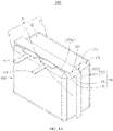
FIG. 1A is a stereoscopic schematic diagram of a battery core according to an embodiment of this application; -
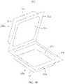
FIG. 1B is a disassembly schematic diagram of a packaging structure according to an embodiment of this application; -
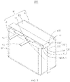
FIG. 2 is a stereoscopic schematic diagram of a battery core according to an embodiment of this application; -
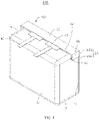
FIG. 3 is a stereoscopic schematic diagram of a battery core according to an embodiment of this application; -
FIG. 4 is a stereoscopic schematic diagram of a battery core according to an embodiment of this application; -
FIG. 5 is a stereoscopic schematic diagram of a battery core according to an embodiment of this application; -
FIG. 6 is a stereoscopic schematic diagram of a battery core according to an embodiment of this application; -
FIG. 7 is a stereoscopic schematic diagram of a battery core according to an embodiment of this application; -
FIG. 8 is a stereoscopic schematic diagram of a battery core according to an embodiment of this application; and -
FIG. 9 is a stereoscopic schematic diagram of a battery core according to an embodiment of this application. - This application will be further described in the following embodiments with reference to the foregoing accompanying drawings.
- The following clearly and completely describes the technical solutions in the embodiments of this application with reference to the accompanying drawings in the embodiments of this application. Apparently, the described embodiments are merely some but not all of the embodiments of this application. All other embodiments obtained by a person of ordinary skill in the art based on the embodiments of this application without creative efforts fall within the protection scope of this application.
- Unless otherwise defined, all technical and scientific terms used herein shall have the same meanings as those commonly understood by a person skilled in the technical field of this application. The terms used herein in the specification of this application are only used to describe specific embodiments, and are not intended to limit this application.
- The following describes in detail some embodiments of this application with reference to the accompanying drawings. Without conflicts, the following embodiments and features in the embodiments can be combined with each other.
- Referring to
FIG. 1A to FIG. 9 , apackaging structure 100 includes afirst housing 100a and asecond housing 100b. - In some embodiments, the
first housing 100a is provided with a firstconcave portion 10a and a firstouter edge 30a connected to an opening of the firstconcave portion 10a. Thesecond housing 100b includes afirst region 10b and a secondouter edge 30b connected to an edge of thefirst region 10b. - The
first housing 100a and thesecond housing 100b are disposed opposite to each other and connected. The firstconcave portion 10a and thefirst region 10b are disposed opposite to each other, and the opening of the firstconcave portion 10a is connected to a peripheral edge of thefirst region 10b to form anaccommodating portion 10, that is, a packaging body. The firstouter edge 30a is corresponding to and combined with the secondouter edge 30b to form a sealingportion 30 that extends beyond theaccommodating portion 10, that is, a connecting portion. The sealingportion 30, that is, the connecting portion, is disposed at a junction of the firstconcave portion 10a and thefirst region 10b. - The sealing
portion 30 is disposed on the surface of theaccommodating portion 10 and is folded toward theaccommodating portion 10. Thepackaging structure 100 may further include anadhesive layer 60. Theadhesive layer 60 bonds theaccommodating portion 10 and a surface of the sealingportion 30 that faces theaccommodating portion 10. - The
accommodating portion 10 includes afirst surface 11, asecond surface 13, afirst side surface 15 and asecond side surface 17. Thefirst surface 11 and thesecond surface 13 are disposed oppose to each other, thefirst side surface 15 is connected to thefirst surface 11 and thesecond surface 13, and thesecond side surface 17 is connected to thefirst surface 11 and thesecond surface 13, and intersects with thefirst side surface 15 at afirst side 101. - In some embodiments, a width of the sealing
portion 30 extending out of theaccommodating portion 10 may be, but is not limited to, 0.7 mm to 2.7 mm. In some embodiments, the width of the sealingportion 30 extending out of theaccommodating portion 10 is 1.7 mm. - The sealing
portion 30 includes afirst sealing portion 31 connected to thefirst side surface 15, asecond sealing portion 33 connected to thesecond side surface 17, and athird sealing portion 35 connected to thefirst sealing portion 31 and thesecond sealing portion 33. - The
adhesive layer 60 may be bonded between at least one of these pairs: thefirst side surface 15 and a surface of thefirst sealing portion 31 that faces thefirst side surface 15, theaccommodating portion 10 and a surface of thesecond sealing portion 33 that faces theaccommodating portion 10, and theaccommodating portion 10 and a surface of thethird sealing portion 35 that faces theaccommodating portion 10. - In some embodiments, referring to
FIG. 1A andFIG. 1B , a junction of the sealingportion 30 and theaccommodating portion 10 is located between a plane at which thefirst surface 11 is located and a plane at which thesecond surface 13 is located. In this case, thefirst region 10b is a concave portion, that is, a second concave portion. The firstconcave portion 10a and the second concave portion are disposed opposite to each other to form theaccommodating portion 10. The opening of the firstconcave portion 10a is connected to an opening of the second concave portion, which means that the packaging body has a double-concave portion structure. - The first
concave portion 10a includes thefirst surface 11 and afirst side wall 15a formed by extending from an edge of the first surface and surrounding thefirst surface 11. The second concave portion includes thesecond surface 13 and asecond side wall 15b formed by extending from an edge of thesecond surface 13 and surrounding thesecond surface 13. - The
first sealing portion 31, that is, the first connecting portion, is bent toward a region of theaccommodating portion 10 corresponding to thefirst housing 100a. Specifically, thefirst sealing portion 31 is folded in a direction extending away from thesecond surface 13. An included angle between thefirst sealing portion 31 and thefirst side wall 15a is less than 90 degrees. Preferably, the included angle between thefirst sealing portion 31 and thefirst side wall 15a is less than 10 degrees. - The
third sealing portion 35 extends from thefirst sealing portion 31 and beyond thefirst side 101, and thethird sealing portion 35 is folded toward a plane at which thesecond side surface 17 is located. Thethird sealing portion 35 includes afirst intersecting side 301 connected to thefirst sealing portion 31. Thesecond sealing portion 33 is folded toward thesecond surface 13. - Specifically, the
adhesive layer 60 includes a firstadhesive layer 61 bonded between thefirst side surface 15 and a surface of thefirst sealing portion 31 that faces thefirst side surface 15. - In some embodiments, referring to
FIG. 2 , theadhesive layer 60 may also be bonded between thesecond side surface 17 and a surface of thesecond sealing portion 33 that faces thesecond side surface 17, or referring toFIG. 3 , theadhesive layer 60 may also include a fourthadhesive layer 67 bonded between thesecond side surface 17 and a surface of thethird sealing portion 35 that faces thesecond side surface 17. - The
second sealing portion 33 includes a first portion 331 (that is, a second connecting portion) and asecond portion 333, and thefirst portion 331 and thesecond portion 333 intersect at a second side 105 (that is, a second intersecting side). Thefirst portion 331 is connected to thesecond side surface 17, and thefirst portion 331, that is, the second connecting portion, is bent toward a region of theaccommodating portion 10 corresponding to thesecond housing 100b. Specifically, an included angle between thefirst portion 331 and thesecond side wall 15b is less than 90 degrees. Preferably, the included angle between thefirst portion 331 and thesecond side wall 15b is less than 10 degrees. Thesecond portion 333 is connected to thefirst portion 331 and thethird sealing portion 35, and thesecond portion 333 is folded along thesecond side 105 on a surface of thefirst portion 331 facing away from theaccommodating portion 10. - The
third sealing portion 35 and thesecond portion 333 constitute a third connecting portion to connect the first connecting portion (that is, the first sealing portion 31) and the second connecting portion (that is, the first portion 331). Thesecond portion 333 overlaps thefirst portion 331. - An included angle between the
first intersecting side 301 and thesecond side 105 is greater than or equal to 90 degrees. - In some embodiments, the third connecting portion may be in a shape of a right-angled trapezoid.
- Specifically, the
adhesive layer 60 may further include a secondadhesive layer 63 disposed between thefirst portion 331 and thesecond side surface 17. - In some embodiments, referring to
FIG. 3 , theadhesive layer 60 may also be extended from between thesecond side surface 17 and a surface of thethird sealing portion 35 that faces thesecond side surface 17 to a region of thesecond portion 333 that faces thefirst portion 331 and a region of thefirst portion 331 that faces thesecond portion 333. - Preferably, the
first sealing portion 31 does not extend beyond the plane at which thefirst surface 11 is located, thesecond sealing portion 33 does not extend beyond the plane at which thesecond surface 13 is located, and thethird sealing portion 35 does not extend beyond the plane at which thefirst surface 11 is located or the plane at which thesecond surface 13 is located. That is, the sealingportion 30 does not extend beyond theaccommodating portion 10 in a thickness direction of theaccommodating portion 10. More preferably, the sealingportion 30 is located between the plane at which thefirst surface 11 is located and the plane at which thesecond surface 13 is located. - More preferably, the
first sealing portion 31 is stacked on thefirst side surface 15, thesecond sealing portion 33 is stacked on thesecond side surface 17, and thethird sealing portion 35 is stacked on thesecond side surface 17. - In some embodiments, the
first sealing portion 31 may protrude from thefirst surface 11, thesecond sealing portion 33 may protrude from thesecond surface 13, and thethird sealing portion 35 may protrude from thefirst surface 11. When thesecond sealing portion 33 protrudes from thesecond surface 13, the portion of thesecond sealing portion 33 protruding from thesecond surface 13 is stacked on thesecond surface 13, and theadhesive layer 60 may also be disposed between thesecond surface 13 and the portion of thesecond sealing portion 33 protruding from thesecond surface 13 to bond thesecond sealing portion 33 and thesecond surface 13. - In some embodiments, referring to
FIG. 4 ,FIG. 5 andFIG. 6 , the sealingportion 30 is connected to a junction of thesecond surface 13 and thefirst side surface 15, and a junction of thesecond surface 13 and thesecond side surface 17. Specifically, thefirst sealing portion 31 is connected to the junction of thesecond surface 13 and thefirst side surface 15, and thesecond sealing portion 33 is connected to the junction of thesecond surface 13 and thesecond side surface 17. In this case, thefirst region 10b is flat, the firstconcave portion 10a and thefirst region 10b constitute theaccommodating portion 10, and the opening of the firstconcave portion 10a is connected to a peripheral edge of thefirst region 10b. This means that the packaging body has a single-concave portion structure. - In some embodiments, referring to
FIG. 4 andFIG. 5 , thefirst sealing portion 31 is folded in a direction extending away from thesecond surface 13. Thethird sealing portion 35 extends from thefirst sealing portion 31 and beyond thefirst side 101, and thethird sealing portion 35 is folded toward a plane at which thesecond side surface 17 is located. Thesecond sealing portion 33 is stacked on thesecond surface 13. - In this embodiment, the
first sealing portion 31 does not protrude from thefirst surface 11. Preferably, thefirst sealing portion 31 is stacked on thefirst side surface 15. - Referring to
FIG. 5 , theadhesive layer 60 is bonded between thefirst side surface 15 and a surface of thefirst sealing portion 31 that faces thefirst side surface 15. - In some embodiments, referring to
FIG. 4 , theadhesive layer 60 may include a thirdadhesive layer 65 bonded between thesecond surface 13 and a surface of thesecond sealing portion 33 that faces thesecond surface 13. - In some embodiments, referring to
FIG. 5 , theadhesive layer 60 may further be bonded between thesecond side surface 17 and a surface of thethird sealing portion 35 that faces thesecond side surface 17. - In some other embodiments, the
first sealing portion 31 may alternatively protrude from thefirst surface 11. - In some other embodiments, referring to
FIG. 6 , thefirst sealing portion 31 is connected to the junction of thesecond surface 13 and thefirst side surface 15, and thesecond sealing portion 33 is connected to the junction of thesecond surface 13 and thesecond side surface 17. Thefirst sealing portion 31 is folded in a direction extending away from thesecond surface 13. Thethird sealing portion 35 is folded toward thesecond side surface 17. Thesecond sealing portion 33 is folded in a direction extending away from thefirst surface 11. Theadhesive layer 60 may be bonded between thefirst side surface 15 and a surface of thefirst sealing portion 31 that faces thefirst side surface 15, or may be bonded between thesecond side surface 17 and a surface of thethird sealing portion 35 that faces thesecond side surface 17. - In some embodiments, referring to
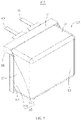
FIG. 7 , the sealingportion 30 is connected to a junction of thefirst surface 11 and thefirst side surface 15, and a junction of thefirst surface 11 and thesecond side surface 17. Specifically, thefirst sealing portion 31 is connected to the junction of thefirst surface 11 and thefirst side surface 15, and thesecond sealing portion 33 is connected to the junction of thefirst surface 11 and thesecond side surface 17. In this case, a region of thefirst housing 100a at which the firstconcave portion 10a is originally disposed is flat and defined as a second region, and thefirst region 10b is a concave portion, namely, a second concave portion. The second concave portion and the second region constitute theaccommodating portion 10, and an opening of the second concave portion is connected to a peripheral edge of the second region. This means that the packaging body has a single-concave portion structure. - The
first sealing portion 31 is folded in a direction extending away from thesecond surface 13, and is on a side of thefirst surface 11 that faces away from thesecond surface 13. Thethird sealing portion 35 extends from thefirst sealing portion 31 and beyond thefirst side 101, and thethird sealing portion 35 is folded toward the plane at which thesecond side surface 17 is located and is on the side of thefirst surface 11 that faces away from thesecond surface 13. Thesecond sealing portion 33 is folded toward thesecond surface 13. - In this embodiment, the
second sealing portion 33 does not protrude from thesecond surface 13. Preferably, thesecond sealing portion 33 is stacked on thesecond side surface 17. - The
adhesive layer 60 is bonded between thesecond side surface 17 and a surface of thesecond sealing portion 33 that faces thesecond side surface 17. - In some other embodiments, the
second sealing portion 33 may alternatively protrude from thesecond surface 13. Preferably, a part of thesecond sealing portion 33 protruding from thesecond surface 13 may further be folded toward thesecond surface 13. Preferably, the portion of thesecond sealing portion 33 protruding from thesecond surface 13 is stacked on thesecond surface 13. In this case, theadhesive layer 60 may also be disposed between thesecond surface 13 and the portion of thesecond sealing portion 33 protruding from thesecond surface 13 to bond thesecond sealing portion 33 and thesecond surface 13. Referring toFIG. 1 to FIG. 9 , the foregoingpackaging structure 100 is applied to abattery core 200. Thebattery core 200 further includes an electrode assembly (not shown), and the electrode assembly includes a first electrode plate, a second electrode plate, and a separator disposed between the first electrode plate and the second electrode plate. Theaccommodating portion 10 accommodates the electrode assembly, and cooperates with the sealingportion 30 to package the electrode assembly. Theaccommodating portion 10 may further accommodate an electrolyte (not shown). - The
battery core 200 further includes afirst tab 41 and asecond tab 43. - In some embodiments, referring to
FIG. 1 to FIG. 7 , thefirst tab 41 is clipped to thefirst sealing portion 31 and extends along thefirst sealing portion 31 so that one end of thefirst tab 41 protrudes from thepackaging structure 100, and the other end of thefirst tab 41 is located in theaccommodating portion 10 to connect the first electrode plate. - The
second tab 43 is clipped to thefirst sealing portion 31 and extends along thefirst sealing portion 31 so that one end of thesecond tab 43 protrudes from thepackaging structure 100, and the other end of thesecond tab 43 is located in theaccommodating portion 10 to connect the second electrode plate. - A part of the
first tab 41 protruding from thefirst sealing portion 31 and a part of thesecond tab 43 protruding from thefirst sealing portion 31 may be arranged along the direction of thefirst side surface 15, and extend beyond thefirst surface 11 to facilitate connection with other electronic elements. - In some embodiments, referring to
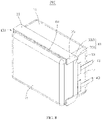
FIG. 8 , thefirst tab 41 is clipped to thesecond sealing portion 33 and extends along thesecond sealing portion 33 so that one end of thefirst tab 41 protrudes from thepackaging structure 100, and the other end of thefirst tab 41 is located in theaccommodating portion 10 to connect the first electrode plate. - The
second tab 43 is clipped to thesecond sealing portion 33 and extends along thesecond sealing portion 33 so that one end of thesecond tab 43 protrudes from thepackaging structure 100, and the other end of thesecond tab 43 is located in theaccommodating portion 10 to connect the second electrode plate. - A part of the
first tab 41 protruding from thesecond sealing portion 33 and a part of thesecond tab 43 protruding from thesecond sealing portion 33 may be arranged along the direction of thesecond side surface 17, and extend beyond thesecond side surface 17 to facilitate connection with other electronic elements. - In some embodiments, the region of the
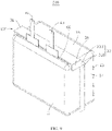
first tab 41 located outside thepackaging structure 100 and the region of thesecond tab 43 located outside thepackaging structure 100 may alternatively be arranged along another direction. For example, referring toFIG. 9 , the portion of thefirst tab 41 protruding from thefirst sealing portion 31 and the portion of thesecond tab 43 protruding from thefirst sealing portion 31 may be arranged perpendicular to thefirst side surface 15. - The
packaging structure 100 in this application has a simple structure. Theadhesive layer 60 bonds the accommodating portion and a face of the sealing portion that faces the accommodating portion, which is conducive to stability of the packaging structure and avoids rebounding of the bent sealing portion. In addition, when thebattery core 200 uses thepackaging structure 100, an adhesive layer is disposed between the accommodating portion and the sealing portion provided with the tab, which helps reducing the risk of direct contact between the tab and the packaging structure. - In addition, a person of ordinary skills in the art can make various changes and modifications based on the technical concept of this application, and all these changes and modifications should fall within the protection scope of this application.
| Packaging structure |
| 100 | |
| |
100a |
| |
100b |
| First |
10a |
| First |
|
| First region | |
| 10b | |
| Second |
|
| Accommodating portion | |
| 10 | |
| |
30 |
| |
60 |
| First |
61 |
| |
63 |
| |
65 |
| |
67 |
| |
11 |
| |
13 |
| |
15 |
| |
17 |
| |
101 |
| |
31 |
| |
33 |
| |
35 |
| |
301 |
| |
331 |
| |
333 |
| |
105 |
| |
200 |
| |
41 |
| |
43 |
Claims (31)
- A packaging structure, comprising: an accommodating portion and a sealing portion; wherein,the accommodating portion comprises a first surface, a second surface, a first side surface, and a second side surface; wherein the first surface and the second surface are disposed opposite to each other, the first side surface is connected to the first surface and the second surface, and the second side surface is connected to the first surface and the second surface and intersects with the first side surface at a first side;the sealing portion comprises a first sealing portion disposed on the first side surface, a second sealing portion disposed on the second side surface, and a third sealing portion connecting the first sealing portion and the second sealing portion;the first sealing portion is folded in a direction away from the second surface;the third sealing portion extends from the first sealing portion and beyond the first side, and the third sealing portion is folded toward a plane at which the second side surface is located; andthe second sealing portion is folded toward the second surface.
- The packaging structure according to claim 1, wherein the sealing portion is connected between a plane at which the first surface is located and a plane at which the second surface is located.
- The packaging structure according to claim 2, wherein the third sealing portion is located between the plane at which the first surface is located and the plane at which the second surface is located.
- The packaging structure according to claim 2, wherein a part of the second sealing portion protruding from the second surface is folded toward the second surface.
- The packaging structure according to claim 1, wherein the sealing portion is connected to a junction of the second surface and the first side surface and a junction of the second surface and the second side surface.
- The packaging structure according to claim 5, wherein the second sealing portion is stacked on the second surface.
- The packaging structure according to claim 1, wherein the sealing portion is connected to a junction of the first surface and the first side surface and a junction of the first surface and the second side surface.
- The packaging structure according to claim 1, wherein an adhesive layer is disposed between the sealing portion and the accommodating portion.
- The packaging structure according to claim 1, wherein the second sealing portion comprises a first portion and a second portion, the first portion intersects the second portion at a second side, the first portion is connected to the second side surface, the second portion is connected to the first portion and the third sealing portion, and the second portion is folded along the second side on a surface of the first portion facing away from the accommodating portion.
- A battery core, comprising:an electrode assembly comprising a first electrode plate, a second electrode plate, and a separator disposed between the first electrode plate and the second electrode plate;a packaging structure according to any one of claims 1 to 9 that packages the electrode assembly.
- The battery core according to claim 10, further comprising:
a tab connected to the first electrode plate and clipped to the first sealing portion or the second sealing portion, wherein the tab protrudes through the packaging structure along the first sealing portion or the second sealing portion. - A packaging structure, comprising: a first housing and a second housing; wherein the first housing is provided with a first concave portion, and an edge of the second housing is connected to that of the first housing to form a packaging body and a connecting portion, wherein the connecting portion is disposed at a junction of the first housing and the second housing; wherein,the connecting portion comprises a first connecting portion and a second connecting portion;the first connecting portion is bent toward the first housing; andthe second connecting portion is bent toward the second housing.
- The packaging structure according to claim 12, wherein the first housing comprises a first surface and a first side wall extending from an edge of the first surface and surrounding the first surface, and an included angle between the first connecting portion and the first side surface is less than 90 degrees.
- The packaging structure according to claim 13, wherein the included angle between the first connecting portion and the first side wall is less than 10 degrees.
- The packaging structure according to claim 13, wherein a first adhesive layer is disposed between the first connecting portion and the first side wall.
- The packaging structure according to claim 12, wherein the second housing is provided with a second concave portion, and the first concave portion and the second concave portion are disposed opposite to each other to form the packaging body.
- The packaging structure according to claim 16, wherein the second housing comprises a second surface and a second side wall extending from an edge of the second surface and surrounding the second surface, and an included angle between the second connecting portion and the second side wall is less than 90 degrees.
- The packaging structure according to claim 17, wherein the included angle between the second connecting portion and the second side wall is less than 10 degrees.
- The packaging structure according to claim 17, wherein a second adhesive layer is disposed between the second connecting portion and the second side wall.
- The packaging structure according to claim 12, wherein the second housing comprises a second surface, the connecting portion is disposed at a junction of the first housing and the second surface, and the second surface is flat.
- The packaging structure according to claim 20, wherein the second connecting portion is disposed on the second surface.
- The packaging structure according to claim 21, wherein a third adhesive layer is disposed between the second connecting portion and the second surface.
- The packaging structure according to claim 12, wherein the connecting portion does not extend beyond the packaging body in a thickness direction of the packaging body.
- The packaging structure according to claim 12, wherein the first housing comprises a first outer edge that extends beyond the packaging body, the second housing comprises a second outer edge that extends beyond the packaging body, and the first outer edge and the second outer edge are connected to form the connecting portion.
- The packaging structure according to claim 12, wherein the connecting portion comprises a third connecting portion that connects the first connecting portion and the second connecting portion.
- The packaging structure according to claim 25, wherein the third connecting portion partially overlaps the first connecting portion or the second connecting portion.
- The packaging structure according to claim 26, wherein a fourth adhesive layer is disposed between the third connecting portion and the first connecting portion or the second connecting portion at an overlapping portion.
- The packaging structure according to claim 25, wherein the third connecting portion comprises a first intersecting side and a second intersecting side that intersect, wherein the first intersecting side is connected to the first connecting portion, the second intersecting side is connected to the second connecting portion, and an included angle between the first intersecting side and the second intersecting side is greater than or equal to 90 degrees.
- The packaging structure according to claim 25, wherein the third connecting portion is approximately in a shape of a right-angled trapezoid.
- A battery core, comprising an electrode assembly, wherein the electrode assembly comprises a first electrode plate, a second electrode plate, and a separator disposed between the first electrode plate and the second electrode plate, wherein the battery core further comprises:
a packaging structure according to any one of claims 12 to 29 that packages the electrode assembly. - The battery core according to claim 30, further comprising:
a tab connected to the first electrode plate and clipped to the first connecting portion or the second connecting portion, wherein the tab protrudes through the packaging structure along the first connecting portion or the second connecting portion.
Applications Claiming Priority (3)
| Application Number | Priority Date | Filing Date | Title |
|---|---|---|---|
| CN201922176539.3U CN211088352U (en) | 2019-12-06 | 2019-12-06 | Package structure and battery cell using the package structure |
| CN202020345930.1U CN212062471U (en) | 2020-03-18 | 2020-03-18 | Packaging structure and battery cell applying same |
| PCT/CN2020/114843 WO2021109670A1 (en) | 2019-12-06 | 2020-09-11 | Packaging structure and battery cell using same |
Publications (2)
| Publication Number | Publication Date |
|---|---|
| EP4089805A1 true EP4089805A1 (en) | 2022-11-16 |
| EP4089805A4 EP4089805A4 (en) | 2024-08-07 |
Family
ID=76222211
Family Applications (1)
| Application Number | Title | Priority Date | Filing Date |
|---|---|---|---|
| EP20895087.3A Pending EP4089805A4 (en) | 2019-12-06 | 2020-09-11 | PACKAGING STRUCTURE AND BATTERY CELL |
Country Status (4)
| Country | Link |
|---|---|
| US (2) | US12322814B2 (en) |
| EP (1) | EP4089805A4 (en) |
| KR (1) | KR102688739B1 (en) |
| WO (1) | WO2021109670A1 (en) |
Families Citing this family (2)
| Publication number | Priority date | Publication date | Assignee | Title |
|---|---|---|---|---|
| CN115347291B (en) * | 2022-10-13 | 2023-03-24 | 宁德新能源科技有限公司 | Electrochemical device and electronic device |
| US20260106282A1 (en) * | 2024-10-11 | 2026-04-16 | Samsung Sdi Co., Ltd. | Battery case and pouch-type secondary battery including the same |
Family Cites Families (21)
| Publication number | Priority date | Publication date | Assignee | Title |
|---|---|---|---|---|
| US6482544B1 (en) * | 2000-06-30 | 2002-11-19 | Mitsubishi Denki Kabushiki Kaisha | Battery package |
| JP4720065B2 (en) | 2001-09-04 | 2011-07-13 | 日本電気株式会社 | Film outer battery and battery pack |
| CN2605667Y (en) * | 2003-03-28 | 2004-03-03 | 东莞新能源电子科技有限公司 | Sealing edge structure of flexible packaging battery cells |
| KR100553753B1 (en) | 2003-10-16 | 2006-02-20 | 삼성에스디아이 주식회사 | Pouch Type Secondary Battery |
| JP2006156161A (en) * | 2004-11-30 | 2006-06-15 | Nec Tokin Tochigi Ltd | Sealed battery |
| CN201069784Y (en) * | 2007-07-25 | 2008-06-04 | 比亚迪股份有限公司 | A soft packing battery |
| CN201146199Y (en) | 2007-12-24 | 2008-11-05 | 比亚迪股份有限公司 | A soft pack battery |
| CN202134624U (en) * | 2011-06-10 | 2012-02-01 | 东莞新能源科技有限公司 | Flexible packaging lithium battery edge sealing structure |
| US20140212701A1 (en) * | 2013-01-29 | 2014-07-31 | Samsung Sdi Co., Ltd. | Battery cell |
| CN203218388U (en) | 2013-04-12 | 2013-09-25 | 东莞新能源科技有限公司 | Flexible-package lithium-ion unit cell |
| CN106356565B (en) * | 2016-10-13 | 2019-09-20 | 安徽巨大电池技术有限公司 | Lithium battery pack |
| CN206250224U (en) | 2016-11-18 | 2017-06-13 | 宁德新能源科技有限公司 | Battery core encapsulating structure |
| CN206422169U (en) | 2016-11-18 | 2017-08-18 | 宁德新能源科技有限公司 | Battery core encapsulating structure |
| CN109997242B (en) * | 2016-12-20 | 2023-06-20 | Sk新能源株式会社 | Pouch type secondary battery |
| CN108574058B (en) * | 2017-03-07 | 2021-06-04 | 宁德新能源科技有限公司 | Soft pack battery |
| KR102256102B1 (en) | 2017-04-26 | 2021-06-03 | 주식회사 엘지에너지솔루션 | Battery cell, battery module comprising the battery cell and battery pack comprising the battery module |
| KR102479721B1 (en) * | 2017-12-04 | 2022-12-21 | 삼성에스디아이 주식회사 | Battery pack |
| EP3734685B1 (en) | 2017-12-27 | 2023-09-06 | Ningde Amperex Technology Limited | Battery |
| DE102018006416A1 (en) | 2018-08-14 | 2020-02-20 | Custom Cells Itzehoe Gmbh | Battery cell with a covering made of a one-piece folded blank made of an aluminum composite film |
| CN211404531U (en) * | 2019-12-06 | 2020-09-01 | 东莞新能德科技有限公司 | Battery packs and electronic devices |
| CN211088352U (en) * | 2019-12-06 | 2020-07-24 | 宁德新能源科技有限公司 | Package structure and battery cell using the package structure |
-
2020
- 2020-09-11 KR KR1020207035673A patent/KR102688739B1/en active Active
- 2020-09-11 WO PCT/CN2020/114843 patent/WO2021109670A1/en not_active Ceased
- 2020-09-11 EP EP20895087.3A patent/EP4089805A4/en active Pending
-
2022
- 2022-03-31 US US17/710,316 patent/US12322814B2/en active Active
- 2022-03-31 US US17/710,509 patent/US12374743B2/en active Active
Also Published As
| Publication number | Publication date |
|---|---|
| EP4089805A4 (en) | 2024-08-07 |
| KR20220060567A (en) | 2022-05-11 |
| US20220223952A1 (en) | 2022-07-14 |
| US12322814B2 (en) | 2025-06-03 |
| KR102688739B1 (en) | 2024-07-25 |
| WO2021109670A1 (en) | 2021-06-10 |
| US20220223951A1 (en) | 2022-07-14 |
| US12374743B2 (en) | 2025-07-29 |
Similar Documents
| Publication | Publication Date | Title |
|---|---|---|
| WO2021110179A1 (en) | Battery, battery assembly, battery pack and electronic apparatus | |
| US12512553B2 (en) | Secondary battery | |
| KR101296964B1 (en) | Battery pack | |
| CN214589035U (en) | Battery and electronic equipment | |
| CN211404531U (en) | Battery packs and electronic devices | |
| US12322814B2 (en) | Packaging structure and battery core using the same | |
| US12142732B2 (en) | Battery cell and electrochemical device including same | |
| WO2022213379A1 (en) | Battery cell and electrical device | |
| US20250046924A1 (en) | Battery and electronic device | |
| CN212625976U (en) | Battery and electronic device with same | |
| EP4604280A1 (en) | Packaging bag, battery cell, and electrical device | |
| JP2007200589A (en) | Laminate battery | |
| WO2025251862A1 (en) | Battery cell assembly, battery, and electric device | |
| US20230037967A1 (en) | Packaging structure and electrochemical device applying packaging structure | |
| CN217468608U (en) | Battery with a battery cell | |
| US20250038322A1 (en) | Electrochemical device, battery module, and electronic device | |
| CN114747070B (en) | Batteries, battery components, battery packs and electronic devices | |
| CN211088352U (en) | Package structure and battery cell using the package structure | |
| CN212625794U (en) | Battery and electronic device with same | |
| WO2023151699A1 (en) | Battery | |
| CN115954588A (en) | Packaging bags, electrochemical devices and electronic equipment | |
| CN212062471U (en) | Packaging structure and battery cell applying same | |
| CN118763265A (en) | Electrochemical devices and electronic devices | |
| CN219163637U (en) | Battery cell assembly | |
| CN222995471U (en) | Batteries and electronic devices |
Legal Events
| Date | Code | Title | Description |
|---|---|---|---|
| STAA | Information on the status of an ep patent application or granted ep patent |
Free format text: STATUS: THE INTERNATIONAL PUBLICATION HAS BEEN MADE |
|
| PUAI | Public reference made under article 153(3) epc to a published international application that has entered the european phase |
Free format text: ORIGINAL CODE: 0009012 |
|
| STAA | Information on the status of an ep patent application or granted ep patent |
Free format text: STATUS: REQUEST FOR EXAMINATION WAS MADE |
|
| 17P | Request for examination filed |
Effective date: 20220706 |
|
| AK | Designated contracting states |
Kind code of ref document: A1 Designated state(s): AL AT BE BG CH CY CZ DE DK EE ES FI FR GB GR HR HU IE IS IT LI LT LU LV MC MK MT NL NO PL PT RO RS SE SI SK SM TR |
|
| DAV | Request for validation of the european patent (deleted) | ||
| DAX | Request for extension of the european patent (deleted) | ||
| A4 | Supplementary search report drawn up and despatched |
Effective date: 20240704 |
|
| RIC1 | Information provided on ipc code assigned before grant |
Ipc: H01M 50/547 20210101ALI20240628BHEP Ipc: H01M 50/543 20210101ALI20240628BHEP Ipc: H01M 50/198 20210101ALI20240628BHEP Ipc: H01M 50/186 20210101ALI20240628BHEP Ipc: H01M 50/184 20210101ALI20240628BHEP Ipc: H01M 50/105 20210101AFI20240628BHEP |