EP4089804A1 - Battery and battery apparatus - Google Patents
Battery and battery apparatus Download PDFInfo
- Publication number
- EP4089804A1 EP4089804A1 EP21187328.6A EP21187328A EP4089804A1 EP 4089804 A1 EP4089804 A1 EP 4089804A1 EP 21187328 A EP21187328 A EP 21187328A EP 4089804 A1 EP4089804 A1 EP 4089804A1
- Authority
- EP
- European Patent Office
- Prior art keywords
- segment
- battery
- pole assembly
- busbar
- disposed
- Prior art date
- Legal status (The legal status is an assumption and is not a legal conclusion. Google has not performed a legal analysis and makes no representation as to the accuracy of the status listed.)
- Pending
Links
Images





Classifications
-
- H—ELECTRICITY
- H01—ELECTRIC ELEMENTS
- H01M—PROCESSES OR MEANS, e.g. BATTERIES, FOR THE DIRECT CONVERSION OF CHEMICAL ENERGY INTO ELECTRICAL ENERGY
- H01M50/00—Constructional details or processes of manufacture of the non-active parts of electrochemical cells other than fuel cells, e.g. hybrid cells
- H01M50/10—Primary casings; Jackets or wrappings
- H01M50/102—Primary casings; Jackets or wrappings characterised by their shape or physical structure
- H01M50/103—Primary casings; Jackets or wrappings characterised by their shape or physical structure prismatic or rectangular
-
- H—ELECTRICITY
- H01—ELECTRIC ELEMENTS
- H01M—PROCESSES OR MEANS, e.g. BATTERIES, FOR THE DIRECT CONVERSION OF CHEMICAL ENERGY INTO ELECTRICAL ENERGY
- H01M50/00—Constructional details or processes of manufacture of the non-active parts of electrochemical cells other than fuel cells, e.g. hybrid cells
- H01M50/50—Current conducting connections for cells or batteries
- H01M50/502—Interconnectors for connecting terminals of adjacent batteries; Interconnectors for connecting cells outside a battery casing
- H01M50/503—Interconnectors for connecting terminals of adjacent batteries; Interconnectors for connecting cells outside a battery casing characterised by the shape of the interconnectors
-
- H—ELECTRICITY
- H01—ELECTRIC ELEMENTS
- H01M—PROCESSES OR MEANS, e.g. BATTERIES, FOR THE DIRECT CONVERSION OF CHEMICAL ENERGY INTO ELECTRICAL ENERGY
- H01M50/00—Constructional details or processes of manufacture of the non-active parts of electrochemical cells other than fuel cells, e.g. hybrid cells
- H01M50/20—Mountings; Secondary casings or frames; Racks, modules or packs; Suspension devices; Shock absorbers; Transport or carrying devices; Holders
- H01M50/204—Racks, modules or packs for multiple batteries or multiple cells
- H01M50/207—Racks, modules or packs for multiple batteries or multiple cells characterised by their shape
- H01M50/209—Racks, modules or packs for multiple batteries or multiple cells characterised by their shape adapted for prismatic or rectangular cells
-
- H—ELECTRICITY
- H01—ELECTRIC ELEMENTS
- H01M—PROCESSES OR MEANS, e.g. BATTERIES, FOR THE DIRECT CONVERSION OF CHEMICAL ENERGY INTO ELECTRICAL ENERGY
- H01M50/00—Constructional details or processes of manufacture of the non-active parts of electrochemical cells other than fuel cells, e.g. hybrid cells
- H01M50/50—Current conducting connections for cells or batteries
- H01M50/502—Interconnectors for connecting terminals of adjacent batteries; Interconnectors for connecting cells outside a battery casing
- H01M50/505—Interconnectors for connecting terminals of adjacent batteries; Interconnectors for connecting cells outside a battery casing comprising a single busbar
-
- H—ELECTRICITY
- H01—ELECTRIC ELEMENTS
- H01M—PROCESSES OR MEANS, e.g. BATTERIES, FOR THE DIRECT CONVERSION OF CHEMICAL ENERGY INTO ELECTRICAL ENERGY
- H01M50/00—Constructional details or processes of manufacture of the non-active parts of electrochemical cells other than fuel cells, e.g. hybrid cells
- H01M50/50—Current conducting connections for cells or batteries
- H01M50/502—Interconnectors for connecting terminals of adjacent batteries; Interconnectors for connecting cells outside a battery casing
- H01M50/509—Interconnectors for connecting terminals of adjacent batteries; Interconnectors for connecting cells outside a battery casing characterised by the type of connection, e.g. mixed connections
-
- H—ELECTRICITY
- H01—ELECTRIC ELEMENTS
- H01M—PROCESSES OR MEANS, e.g. BATTERIES, FOR THE DIRECT CONVERSION OF CHEMICAL ENERGY INTO ELECTRICAL ENERGY
- H01M50/00—Constructional details or processes of manufacture of the non-active parts of electrochemical cells other than fuel cells, e.g. hybrid cells
- H01M50/50—Current conducting connections for cells or batteries
- H01M50/502—Interconnectors for connecting terminals of adjacent batteries; Interconnectors for connecting cells outside a battery casing
- H01M50/514—Methods for interconnecting adjacent batteries or cells
- H01M50/516—Methods for interconnecting adjacent batteries or cells by welding, soldering or brazing
-
- H—ELECTRICITY
- H01—ELECTRIC ELEMENTS
- H01M—PROCESSES OR MEANS, e.g. BATTERIES, FOR THE DIRECT CONVERSION OF CHEMICAL ENERGY INTO ELECTRICAL ENERGY
- H01M50/00—Constructional details or processes of manufacture of the non-active parts of electrochemical cells other than fuel cells, e.g. hybrid cells
- H01M50/50—Current conducting connections for cells or batteries
- H01M50/531—Electrode connections inside a battery casing
- H01M50/533—Electrode connections inside a battery casing characterised by the shape of the leads or tabs
-
- H—ELECTRICITY
- H01—ELECTRIC ELEMENTS
- H01M—PROCESSES OR MEANS, e.g. BATTERIES, FOR THE DIRECT CONVERSION OF CHEMICAL ENERGY INTO ELECTRICAL ENERGY
- H01M50/00—Constructional details or processes of manufacture of the non-active parts of electrochemical cells other than fuel cells, e.g. hybrid cells
- H01M50/50—Current conducting connections for cells or batteries
- H01M50/543—Terminals
- H01M50/547—Terminals characterised by the disposition of the terminals on the cells
- H01M50/548—Terminals characterised by the disposition of the terminals on the cells on opposite sides of the cell
-
- H—ELECTRICITY
- H01—ELECTRIC ELEMENTS
- H01M—PROCESSES OR MEANS, e.g. BATTERIES, FOR THE DIRECT CONVERSION OF CHEMICAL ENERGY INTO ELECTRICAL ENERGY
- H01M50/00—Constructional details or processes of manufacture of the non-active parts of electrochemical cells other than fuel cells, e.g. hybrid cells
- H01M50/50—Current conducting connections for cells or batteries
- H01M50/543—Terminals
- H01M50/564—Terminals characterised by their manufacturing process
- H01M50/566—Terminals characterised by their manufacturing process by welding, soldering or brazing
-
- H—ELECTRICITY
- H01—ELECTRIC ELEMENTS
- H01M—PROCESSES OR MEANS, e.g. BATTERIES, FOR THE DIRECT CONVERSION OF CHEMICAL ENERGY INTO ELECTRICAL ENERGY
- H01M50/00—Constructional details or processes of manufacture of the non-active parts of electrochemical cells other than fuel cells, e.g. hybrid cells
- H01M50/50—Current conducting connections for cells or batteries
- H01M50/543—Terminals
- H01M50/552—Terminals characterised by their shape
- H01M50/553—Terminals adapted for prismatic, pouch or rectangular cells
- H01M50/555—Window-shaped terminals
-
- Y—GENERAL TAGGING OF NEW TECHNOLOGICAL DEVELOPMENTS; GENERAL TAGGING OF CROSS-SECTIONAL TECHNOLOGIES SPANNING OVER SEVERAL SECTIONS OF THE IPC; TECHNICAL SUBJECTS COVERED BY FORMER USPC CROSS-REFERENCE ART COLLECTIONS [XRACs] AND DIGESTS
- Y02—TECHNOLOGIES OR APPLICATIONS FOR MITIGATION OR ADAPTATION AGAINST CLIMATE CHANGE
- Y02E—REDUCTION OF GREENHOUSE GAS [GHG] EMISSIONS, RELATED TO ENERGY GENERATION, TRANSMISSION OR DISTRIBUTION
- Y02E60/00—Enabling technologies; Technologies with a potential or indirect contribution to GHG emissions mitigation
- Y02E60/10—Energy storage using batteries
Definitions
- the disclosure relates to the technical field of batteries, in particular to a battery and a battery apparatus.
- the battery in the related art needs to be connected in series and parallel in the packing process. Due to the limitation of battery structure, the connection of poles between batteries in the battery packing process in the related art is extremely inconvenient.
- a battery including: two opposite first surfaces and four second surfaces disposed around the first surfaces, wherein an area of the first surface is larger than an area of the second surface; a pole assembly, wherein the pole assembly is disposed on the first surface; a busbar, wherein the busbar is bent into a first segment and a second segment, the first segment is located at a side of the first surface disposed with the pole assembly and is connected to the pole assembly, and the second segment is parallel to or substantially parallel to one of the second surfaces and is used for electrically connecting a pole assembly of another battery.
- a battery apparatus including a first battery and a second battery, the first battery including: two opposite first surfaces and four second surfaces disposed around the first surfaces, wherein an area of the first surface is larger than an area of the second surface; a first pole assembly, wherein the first pole assembly is disposed on the first surface; a first busbar, wherein the first busbar is bent into a first segment and a second segment, the first segment is located at a side of the first surface disposed with the first pole assembly and is connected to the first pole assembly, and the second segment parallel to or substantially parallel to one of the second surfaces; the second battery, including a second pole assembly; and the first battery, disposed side by side with the second battery, such that the second segment is connected to the second pole assembly.
- connection In particular, a reference to “the” object or “a” and “an” object is intended to denote also one of a possible plurality of such objects.
- the terms “connect”, “fix” should be broadly interpreted, for example, the term “connect” can be “fixedly connect”, “detachably connect”, “integrally connect”, “electrically connect” or “signal connect”.
- the term “connect” also can be “directly connect” or “indirectly connect via a medium”.
- the battery includes: two opposite first surfaces 12 and four second surfaces 13 disposed around the first surfaces 12, an area of the first surface 12 larger than an area of the second surface 13; a pole assembly 110, the pole assembly 110 disposed on the first surface 12; a busbar 120, the busbar 120 bent into a first segment 31 and a second segment 32.
- the first segment 31 is located at a side of the first surface 12 disposed with the pole assembly 110 and is connected to the pole assembly 110
- the second segment 32 is parallel to or substantially parallel to a second surface 13 and is used for electrically connecting a pole assembly of another battery.
- the battery of an embodiment of the disclosure includes a pole assembly 110 and a busbar 120.
- the pole assembly 110 is disposed on the first surface 12 of the battery; that is, the pole assembly 110 is disposed on a large surface of the battery.
- the first segment 31 of the busbar 120 is connected to the pole assembly 110 and is directly opposite to the first surface 12, and the second segment 32 of the busbar 120 is parallel to or substantially parallel to the second surface 13, so as to facilitate electrical connection with the pole assembly of another battery.
- the second segment 32 of the busbar 120 may be connected to the busbar of another battery.
- the busbar 120 is electrically connected to the pole assembly of another battery through the busbar of another battery, or the busbar 120 may also be used for connecting other structures, such as cables.
- the busbar 120 may be directly connected to the pole assembly of another battery.
- the battery includes a battery body 100, and the battery body 100 includes two opposite first surfaces 12 and four second surfaces 13 disposed around the first surfaces 12.
- the battery body 100 has an approximately rectangular structure. In other words, while ignoring processing and manufacturing errors, the battery body 100 may have a rectangular structure.
- the two opposite first surfaces 12 are large surfaces of the battery body 100, and the four second surfaces 13 are small surfaces of the battery body 100.
- the four second surfaces 13 include two pairs of small surfaces, namely a first pair of small surfaces extending along a length direction of the battery body 100, and a second pair of small surfaces extending along a width direction of the battery body 100.
- An area of the first pair of small surfaces is larger than an area of the second pair of small surfaces, but both are smaller than an area of the large surface.
- the pole assembly 110 is disposed on the first surface 12 to ensure that the pole assembly 110 has a reliable supporting surface, so as to ensure the stability of the pole assembly 110.
- the orthographic projections of the first segment 31 and the pole assembly 110 on a first surface 12 at least partially overlap. That is, the first segment 31 and the pole assembly 110 may be directly connected, and the connection is extremely convenient.
- orthographic projections of the first segment 31 and the pole assembly 110 on the first surface 12 do not overlap; that is, the first segment 31 and the pole assembly 110 may be connected by a metal connecting piece.
- the second segment 32 and the second surface 13 are parallel or substantially parallel, where the slight parallelism here actually ignores manufacturing errors and the like.
- the second segment 32 may be parallel to the first pair of small surfaces extending along the length direction of the battery body 100, or the second segment 32 may be parallel to the second pair of small surfaces extending along the width direction of the battery body 100.
- the first segment 31 and the first surface 12 are parallel or substantially parallel.
- the first segment 31 and the first surface 12 can be made parallel or substantially parallel, wherein an angle between the first segment 31 and the second segment 32 is a right angle.
- the first segment 31 may be disposed obliquely to the first surface 12, wherein an angle between the first segment 31 and the second segment 32 may be an acute angle or an obtuse angle.
- first segment 31 and the second segment 32 are substantially perpendicular, so as to ensure the convenient connection of the busbar 120 and that the battery disposition space can be effectively used. If various types of errors are ignored, the first segment 31 and the second segment 32 may be disposed vertically.
- an included angle between the first segment 31 and the second segment 32 may be 80 degrees to 100 degrees. Further, the included angle between the first segment 31 and the second segment 32 may be 85 degrees to 95 degrees.
- first segment 31 and the second segment 32 are substantially vertical has taken into account of specific process errors. That is, if the processing and manufacturing errors are ignored, the angle formed between the first segment 31 and the second segment 32 is a right angle.
- the included angle between the first segment 31 and the second segment 32 may be 80 degrees to 100 degrees. Further, the included angle between the first segment 31 and the second segment 32 may be 85 degrees to 95 degrees.
- the first segment 31 and the second segment 32 when the first segment 31 transitions to the second segment 32 in an arc-shape, the first segment 31 and the second segment 32 here being substantially vertical is to emphasize the overall extension direction of the two; it is not specifically indicated that there must be a right-angle transition between the first segment 31 and the second segment 32.
- an orthographic projection of the second segment 32 on a plane of the first surface 12 is located outside the first surface 12.
- one end of the first segment 31 needs to extend outside of the circumferential outer edge the battery body 100, such that the second segment 32 is not located in a three-dimensional space where the circumferential outer edge of the battery body 100 is located, thereby facilitating subsequent connection.
- At least part of an orthographic projection of the second segment 32 on a plane where the first surface 12 is located is located inside the first surface 12.
- one end of the first segment 31 may not need to extend outside of the circumferential outer edge of another battery body 100, such that the second segment 32 may be located in the three-dimensional space where the circumferential outer edge of the battery body 100 is located.
- the second segment 32 may directly extend to the pole assembly of the other battery for connection (that is, the pole assemblies of the two batteries may be directly opposite), or the second segment 32 may also be connected to the busbar of another battery.
- the busbar 120 is bent toward a direction away from the first surface 12; that is, the busbar 120 increases the occupied space in a height direction of the battery.
- the busbar 120 is bent toward a direction close to the first surface 12; that is, the busbar 120 does not increase the occupied space in the height direction of the battery.
- the two busbars 120 are respectively connected to the two pole assemblies 110, such that the two pole assemblies 110 are electrically connected with other components through the two busbars 120.
- the two pole assemblies 110 are disposed on the same first surface 12.
- the busbar 120 on one pole assembly 110 is bent toward a direction away from the first surface 12, and the busbar 120 on the other pole assembly 110 is bent toward a direction close to the first surface 12, so as to facilitate convenient connection of the battery to external components.
- the two busbars 120 may be extended to two sides of the another battery, so as to facilitate the connection.
- the two pole assemblies 110 may be respectively disposed on the two first surfaces 12.
- the first segment 31 may be welded to the pole assembly 110 so as to ensure the stability of the connection.
- the thickness of the welded portion of the first segment 31 and the pole assembly 110 is smaller than the thickness of the second segment 32, so as to facilitate convenient welding of the first segment 31 and the pole assembly 110. Specifically, it may be understood that portion which the first segment 31 connecting with the pole assembly 10 is thinned, such that the first segment 31 and the pole assembly 110 can be rapidly welded by the welding energy.
- first segment 31 may be partially thinned. Of course, the first segment 31 may be overall thinned.
- the busbar 120 and the pole assembly 110 may be an integrated structure. That is, the busbar 120 and the pole assembly 110 are an integral structure, with relative simple structure and relatively high stability.
- the integral structure may be multiple independent parts that are fixedly connected after molding. In other words, the busbar 120 and the pole assembly 110 have been connected before the battery assembly, instead of being connected during the battery assembly process.
- the integral structure may also be an integrally formed structure; that is, the busbar 120 and the pole assembly 110 are integrally formed.
- the pole assembly 110 may be disposed protruding from the battery body 100, or may be accommodated in the battery body 100. In other words, a groove may be provided in the battery body 100 for accommodating the pole assembly 110.
- the pole assembly 110 and the recess 101 may be located on the two first surfaces 12 respectively, or both may be located on the same first surface 12.
- the battery body 100 is provided with a recess 101, so as to accommodate the pole assembly of another battery during battery packing, such that the pole assembly does not occupy the space between the two batteries, and the distance between two adjacent batteries is reduced, thereby increasing the energy density of the battery packing.
- the recess 101 on the battery body 100 is used for accommodating the pole assembly of another battery. That is, when two batteries are packed, the pole assembly protruding from the other battery may be accommodated in the recess 101.
- the battery body 100 includes: a cell 14, wherein the cell 14 is connected to the pole assembly 110; and a housing 15, wherein the cell 14 is located in the housing 15.
- the recess 101 and the pole assembly 110 are both disposed on the housing 15, which is not only convenient for assembly but also has a relatively simple structure.
- the housing 15 may be configured for the assembly of the pole assembly 110.
- the material of the housing 15 may be stainless steel or aluminum, which has good corrosion resistance and sufficient strength.
- the thickness of the housing 15 is uniform, which not only has strong structural stability, but also facilitates processing.
- the housing 15 includes: a first housing 151; and a second housing 152, wherein the second housing 152 is connected to the first housing 151 so as to close the cell 14.
- the first housing 151 and the second housing 152 are disposed separately, which can facilitate the assembly of the cell 14 and convenient processing.
- the recess 101 and the pole assembly 110 may both be disposed on the first housing 151, or the recess 101 and the pole assembly 110 may both be provided on the second housing 152.
- one of the recess 101 and the pole assembly 110 is disposed on the first housing 151, and the other one of the recess 101 and the pole assembly 110 is disposed on the second housing 152, so as to ensure sufficient assembly space and ensure the strength of the structure.
- the first housing 151 and the second housing 152 may both be formed with an accommodating cavity 153.
- the cell 14 is located in a cavity formed by the two accommodating cavities 153. Depths of the accommodating cavity 153 of the first housing 151 and the second housing 152 may be the same or different; no limitation is imposed here.
- the first housing 151 is a flat plate.
- the second housing 152 is formed with an accommodating cavity 153, and the cell 14 is located in the accommodating cavity 153.
- the disposition of the flat plate may facilitate subsequent connections and is less difficult to process.
- a protruding edge 154 is disposed on the circumferential edge of the second housing 152, and the first housing 151 is welded to the protruding edge 154, so as to ensure that the first housing 151 and the second housing 152 are reliably welded, thereby providing a connection stability.
- the disposition of the protruding edge 154 is mainly to ensure that the welding area is increased, thereby improving the stability of the welding.
- the circumferential edge of the first housing 151 may also be disposed with a protruding edge 154.
- the protruding edge 154 of the first housing 151 is welded to the protruding edge 154 of the second housing 152.
- the protruding edge 154 may be understood as a flange, such as a flange formed by extending outward from the circumferential outer edge of a flat plate, or a flange formed by extending outward on a side wall of a structure having an accommodating cavity 153, wherein the flange is substantially perpendicular to the side wall.
- a flange such as a flange formed by extending outward from the circumferential outer edge of a flat plate, or a flange formed by extending outward on a side wall of a structure having an accommodating cavity 153, wherein the flange is substantially perpendicular to the side wall.
- the cell 14 includes a cell main body 141 and a tab 142, and the tab 142 extends from the length direction of the cell main body 141, wherein the tab 142 is connected with the pole assembly 110.
- the pole assembly 110 may be disposed at the end of the battery body 100 to facilitate the connection and can fully use the space along the length direction.
- the tab 142 and the pole assembly 110 may be directly connected; that is, the tab 142 and the pole assembly 110 may be directly welded.
- the tab 142 and the pole assembly 110 may be connected by a metal adapter piece, and the specific connection method may be welding, or the use of riveting and the like; no limitation is imposed here.
- the cell main body 141 includes more than two electrode sheets, and the tab 142 includes more than two single-piece tabs.
- the single-piece tabs respectively extend from the corresponding electrode sheets, and the width of the single-piece tabs is smaller than the width of the electrode sheet.
- Multiple single-piece tabs are stacked to form a tab 142, which is connected with the pole assembly 110, wherein the tab 142 may be welded to the pole assembly 110.
- the single-piece tabs are made of metal foil with good electrical and thermal conductivity, such as aluminum, copper, or nickel.
- the positive pole assembly is connected with the positive tab, and the negative pole assembly is connected with the negative tab.
- pole assembly 110 and the housing 15 are disposed insulated from each other.
- an insulating member may be configured for insulation between the two, or an insulating coating may be configured for insulation between the two.
- the insulation method may be based on actual needs; no limitation is imposed herein.
- a length of the battery is a, wherein 400mm ⁇ a ⁇ 2500mm; a width of the battery is b, and the height of the battery is c, wherein 2b ⁇ a ⁇ SOb and/or 0.5c ⁇ b ⁇ 20c.
- a ratio of the length to the width of the battery is larger, and further, a ratio of the width to the height of the battery is larger.
- a length of the battery is a
- a width of the battery is b, wherein 4b ⁇ a ⁇ 7b.
- a ratio of the length to the width of the battery in the present embodiment is larger, thereby increasing the energy density of the battery and facilitating the subsequent formation of the battery module.
- the height of the battery is c, wherein 3c ⁇ b ⁇ 7c, and a ratio of the battery width to the height is relatively large, which also ensures formation of the battery module while ensuring sufficient energy density.
- a length of the battery may be 500mm-1500mm, a width of the battery may be 80mm-150mm, and a height of the battery may be 15mm-25mm.
- the length of the battery is a size of the battery in a length direction
- the width of the battery is a size of the battery in the width direction
- the height of the battery is a size of the battery in the height direction, namely a thickness of the battery.
- the battery is a laminated battery, which not only is convenient for packing, but also may be processed to obtain a battery of longer length.
- the cell 14 is a laminated cell.
- the cell 14 has a first electrode sheet laminated with each other, a second electrode sheet electrically opposite to the first electrode sheet, and a separator film disposed between the first electrode sheet and the second electrode sheet, such that multiple pairs of the first electrode sheet and the second electrode sheet are stacked to form a laminated cell.
- the battery may be a wound battery.
- the first electrode sheet, the second electrode sheet that is electrically opposite to the first electrode sheet, and the separator film disposed between the first electrode sheet and the second electrode sheet are wound, so as to obtain the wound battery.
- the battery apparatus includes a first battery 1 and a second battery 2.
- the first battery 1 includes: two opposite first surfaces 12 and four second surfaces 13 disposed around the first surfaces 12, wherein an area of the first surface 12 is greater than an area of the second surface 13; a first pole assembly 20, wherein the first pole assembly 20 is disposed on the first surface 12; and a first busbar 30, wherein the first busbar 30 is bent into a first segment 31 and a second segment 32, the first segment 31 is located at a side of the first surface 12 where the first pole assembly 20 is disposed and is connected to the first pole assembly 20, and the second segment 32 is parallel to or substantially parallel to a second surface 13.
- the second battery 2 includes a second pole assembly 50. The first battery 1 and the second battery 2 are disposed side by side, such that the second segment 32 is connected to the second pole assembly 50.
- the battery apparatus of an embodiment of the disclosure includes the first battery 1 and the second battery 2.
- the first pole assembly 20 of the first battery 1 on the first surface 12, that is, by disposing the first pole assembly 20 on the large surface of the first battery 1, the first segment 31 of the first busbar 30 is connected to the first pole assembly 20 and is directly opposite to the first surface 12, and the second segment 32 of the first busbar 30 and the second surface 13 are parallel or substantially parallel, so as to facilitate electrical connection with the second pole assembly 50 of the second battery 2.
- first battery 1 and the second battery 2 side by side means that the first battery 1 and the second battery 2 are packed together, wherein the first battery 1 and the second battery 2 may be stacked up and down, or left and right; no limitation is imposed herein.
- the second segment 32 of the first busbar 30 may be directly electrically connected to the second pole assembly 50 of the second battery 2.
- the second battery 2 does not need to be disposed with a busbar.
- the second segment 32 of the first busbar 30 may be directly extended to the second pole assembly 50 for connection.
- the second segment 32 may be directly extended to the second pole assembly 50. In such case, the second segment 32 does not need to be too long for the connection.
- the first battery 1 includes a first battery body 10, and the first battery body 10 includes two opposite first surfaces 12 and four second surfaces 13 disposed around the first surfaces 12.
- the second battery 2 includes a second battery body 40, and the second pole assembly 50 is disposed on the second battery body 40.
- the second battery body 40 includes two opposite third surfaces 42 and four fourth surfaces 43 disposed around the third surfaces 42.
- the second battery 2 further includes a second busbar 60, and the second pole assembly 50 is connected to the second segment 32 through the second busbar 60 to facilitate the connection and facilitate the disposition of components, and effectively using the space of the battery apparatus.
- the second battery 2 includes two opposite third surfaces 42 and four fourth surfaces 43 disposed around the third surfaces 42.
- An area of the third surface 42 is larger than an area of the fourth surface 43.
- the second pole assembly 50 is disposed on the third surface 42; that is, the second pole assembly 50 is disposed on the large surface of the second battery 2, so as to ensure that the second pole assembly 50 has a reliable supporting surface, thereby ensuring the stability of the second pole assembly 50.
- the second busbar 60 is bent into a third segment 61 and a fourth segment 62.
- the third segment 61 is located on the side of the third surface 42 where the second pole assembly 50 is disposed, and is connected to the second pole assembly 50.
- the fourth segment 62 is parallel to or substantially parallel to a fourth surface 43 and is connected to the second segment 32. Both the first busbar 30 and the second busbar 60 are bent to facilitate the connection of the second segment 32 and the fourth segment 62, and facilitate the rapid connection between the second segment 32 and the fourth segment 62.
- first surface 12 of the first battery 1 and the third surface 42 of the second battery 2 are disposed oppositely.
- first pole assembly 20 and the second pole assembly 50 may be disposed directly opposite to each other.
- first busbar 30 and the second busbar 60 are directly opposite, and the distance between the second segment 32 and the fourth segment 62 is relatively short.
- the first pole assembly 20 is disposed on one first surface 12 away from the second battery 2, and the second pole assembly 50 is disposed on one third surface 42 close to the first battery 1.
- the first battery body 10 is actually clamped between the first pole assembly 20 and the second pole assembly 50.
- the first pole assembly 20 is disposed on another first surface 12 close to the second battery 2
- the second pole assembly 50 is disposed on another third surface 42 away from the first battery 1. That is, the second battery body 40 is actually clamped between the first pole assembly 20 and the second pole assembly 50.
- the first pole assembly 20 and the second pole assembly 50 are not directly disposed opposite each other. Such design makes the disposition of the battery apparatus more reasonable, and the distance between the first busbar 30 and the second busbar 60 will not be too great.
- a first recess 11 may be provided on the first battery body 10, and the first recess 11 and the first pole assembly 20 may be respectively located on the two first surfaces 12. At this time, the first recess 11 may be used for accommodating the second pole assembly 50 of the second battery 2.
- the projections of the first recess 11 and the first pole assembly 20 along a direction perpendicular to the first battery body 10 at least partially overlap, such that when the first battery 1 and the second battery 2 are packed, the first battery 1 and the second battery 2 may be aligned with each other, so as to ensure that the second pole assembly 50 may be reliably accommodated in the first recess 11.
- the second battery body 40 may also be provided with a second recess 41 thereon.
- the second recess 41 may be used for accommodating a pole assembly of a third battery; no limitation is imposed here.
- the emphasis is that if the pole assembly of the battery is disposed protruding from the battery body, a recess may be provided on another battery so as to accommodate the adjacent pole assembly, such that the distance between the batteries is minimized, thereby increasing the energy density of the battery apparatus.
- an orthographic projection of the second segment 32 on a plane of the first surface 12 is located outside the first surface 12, and an orthographic projection of the fourth segment 62 on a plane where the third surface 42 is located is outside on the third surface 42.
- the second segment 32 and the fourth segment 62 are connected outside the circumferential outer edge of the battery, so as not to occupy the space between the batteries, thereby ensuring the energy density of the battery and facilitating the connection.
- the first busbar 30 is bent toward a direction close to the first surface 12, and the second busbar 60 is bent toward a direction close to the third surface 42.
- the fourth segment 62 and the second segment 32 are connected by an adapter piece 70; that is, the fourth segment 62 is connected with the adapter piece 70, and the second segment 32 is connected with the adapter piece 70, as shown in Figure 8 .
- the fourth segment 62 and the second segment 32 may be directly welded, as shown in Figure 9 .
- the first busbar 30 is bent toward a direction away from the first surface 12, and the second busbar 60 is bent toward a direction away from the third surface 42.
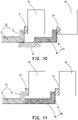
- the fourth segment 62 and the second segment 32 are connected by an adapter piece 70. That is, the fourth segment 62 is connected with the adapter piece 70, and the second segment 32 is connected with the adapter piece 70, as shown in Figure 10 .
- the fourth segment 62 and the second segment 32 are directly welded, as shown in Figure 11 .
- the first busbar 30 is bent toward a direction close to the first surface 12, and the second busbar 60 is bent toward a direction away from the third surface 42; in other words, the distance between the fourth segment 62 and the second segment 32 reaches the minimum.
- the fourth segment 62 and the second segment 32 are connected by the adapter piece 70; that is, the fourth segment 62 is connected with the adapter piece 70, and the second segment 32 is connected with the adapter piece 70.
- the fourth segment 62 and the second segment 32 are directly welded.
- the fourth segment 62 and the second segment 32 may also be disposed overlapped.
- the fourth segment 62 and the second segment 32 may be directly butted; that is, the end face of the fourth segment 62 and the end face of the second segment 32 are directly butted, as shown in Figure 13 , and the first busbar 30 and the second busbar 60 form a U-shaped structure.
- the first busbar 30 is bent toward a direction away from the first surface 12, and the second busbar 60 is bent toward a direction close to the third surface 42; in other words, the distance between the fourth segment 62 and the second segment 32 reaches the maximum.
- the fourth segment 62 and the second segment 32 are connected by the adapter piece 70; that is, the fourth segment 62 is connected with the adapter piece 70, and the second segment 32 is connected with the adapter piece 70.
- connection mode of the fourth segment 62 and the second segment 32 is not limited here, and may be selected according to actual needs.
- the adapter piece 70 is a metal piece, which is not only easy to weld, but also the reliability of welding is strong.
- the fourth segment 62 and the second segment 32 may be directly butted.
- the fourth segment 62 and the second segment 32 may also be disposed overlapped; no limitation is imposed herein.
- the fourth segment 62 and the second segment 32 are disposed overlapped, and the fourth segment 62 is located outside the second segment 32.
- a thickness of a welded portion of the fourth segment 62 and the second segment 32 is smaller than a thickness of the third segment 61, or a thickness of the second busbar 60 is smaller than a thickness of the first busbar 30, so as to facilitate convenient welding between the fourth segment 62 and the second segment 32.
- portion which the fourth segment 62 connecting with the second segment 32 is thinned, such that the fourth segment 62 and the second segment 32 can be rapidly welded by the welding energy.
- the second busbar 60 may partially thin only the fourth segment 62, as shown in Figure 15 .
- the fourth segment 62 may also be overall thinned.
- an overall thickness of the second busbar 60 may be smaller than the thickness of the first busbar 30, which is similar to the overall thinning of the second busbar 60, as shown in Figure 14 .
- the fourth segment 62 and the second segment 32 are disposed overlapped, and the fourth segment 62 is located inside the second segment 32.
- a thickness of a welded portion between the second segment 32 and the fourth segment 62 is smaller than the thickness of the first segment 31, or a thickness of the first busbar 30 is smaller than the thickness of the second busbar 60, so as to facilitate convenient welding between the second segment 32 and the fourth segment 62.
- portion which the fourth segment 62 connecting with the second segment 32 is thinned, such that the second segment 32 and the fourth segment 62 can be rapidly welded by the welding energy.
- first busbar 30 may partially thin only the second segment 32.
- second segment 32 may also be overall thinned.
- an overall thickness of the first busbar 30 may be smaller than the thickness of the second busbar 60, which is similar to the overall thinning of the first busbar 30.
- the first battery body 10 has an approximately rectangular structure.
- the first battery body 10 may have a rectangular structure.
- the second battery body 40 has an approximately rectangular structure.
- the first battery 1 and the second battery 2 may be connected in series. In such case, one first pole assembly 20 is connected to one second pole assembly 50, and the other first pole assembly 20 is connected to the third battery; correspondingly, the other second pole assembly 50 may be connected to a fourth battery.
- the first battery 1 and the second battery 2 may be connected in parallel. In such case, one first pole assembly 20 is connected to one second pole assembly 50, and the other first pole assembly 20 is connected to the other second pole assembly 50.
- the connection relationship between the batteries of the battery apparatus is not limited here, connection in series and in parallel may be selected according to actual needs.
- orthographic projections of the first segment 31 and the first pole assembly 20 on a first surface 12 at least partially overlap.
- the first segment 31 and the first pole assembly 20 may be directly connected, and the connection is very convenient.
- the orthographic projections of the third segment 61 and the second pole assembly 50 on a third surface 42 at least partially overlap. That is, the third segment 61 and the second pole assembly 50 may be directly connected, and the connection is very convenient.
- orthographic projections of the first segment 31 and the first pole assembly 20 on one first surface 12 do not overlap. That is, the first segment 31 and the pole assembly 110 may be connected by a metal connecting piece.
- Orthographic projections of the third segment 61 and the second pole assembly 50 on a third surface 42 do not overlap. That is, the third segment 61 and the second pole assembly 50 may be connected by a metal connecting piece.
- the first battery body 10 includes: the cell 14, wherein the cell 14 is connected to the first pole assembly 20; and the housing 15, wherein the cell 14 is located in the housing 15.
- the first recess 11 and the first pole assembly 20 are both disposed on the housing 15, which is not only convenient for assembly but also has a relatively simple structure, so the housing 15 may be configured for the assembly of the first pole assembly 20.
- the housing 15 includes: the first housing 151; and the second housing 152, wherein the second housing 152 is connected to the first housing 151, so as to close the cell 14.
- the first housing 151 and the second housing 152 are disposed separately, which can facilitate the assembly of the cell 14 and the convenient processing.
- the first housing 151 and the second housing 152 may both be formed with an accommodating cavity 153.
- the cell 14 is located in the cavity formed by the two accommodating cavities 153. Depths of the accommodating cavity 153 of the first housing 151 and the second housing 152 may be the same or different; no limitation is imposed here.
- the first housing 151 is a flat plate
- the second housing 152 is formed with the accommodating cavity 153
- the battery cell 14 is located in the accommodating cavity 153.
- the disposition of the flat plate may facilitate subsequent connections and is less difficult to process.
- a protruding edge 154 is disposed on the circumferential edge of the second housing 152.
- the first housing 151 is welded to the protruding edge 154, so as to ensure that the first housing 151 and the second housing 152 are reliably welded, thereby providing a connection stability.
- the disposition of the protruding edge 154 is mainly to ensure that the welding area is increased, thereby improving the stability of the welding.
- the circumferential edge of the first housing 151 may also be disposed with a protruding edge 154, and the protruding edge 154 of the first housing 151 and the protruding edge 154 of the second housing 152 are welded.
- the cell 14 includes the cell main body 141 and the tab 142.
- the tab 142 extends from the length direction of the cell main body 141, wherein the tab 142 is connected to the first pole assembly 20.
- the first pole assembly 20 may be disposed at the end of the first battery body 10 to facilitate the connection and can fully use the space along the length direction.
- first battery 1 and the second battery 2 may have exactly the same structure.
- the busbar (the first busbar 30 and/or the second busbar 60) and the battery side (the second surface 13 and/or the fourth surface 43) are disposed at intervals, such that reliable electrical isolation is ensured, and that the tooling may be inserted into the gap for fixing during welding, for convenient welding.
- the battery apparatus may further include a third battery.
- the third battery may be one or at least two, and the structure of the third battery is similar or completely the same as the first battery 1 and the second battery 2; details will not be repeated here.
- a length of the first battery 1 is d, wherein 400mm ⁇ d ⁇ 2500mm; a width of the first battery 1 is e, and a height of the first battery 1 is f, wherein 2e ⁇ d ⁇ 50e and/or 0.5 f ⁇ e ⁇ 20f.
- a length of the second battery 2 is d, wherein 400mm ⁇ d ⁇ 2500mm; a width of the second battery 2 is e, and a height of the second battery 2 is f, wherein 2e ⁇ d ⁇ 50e and/or 0.5f ⁇ e ⁇ 20f.
- the length of the first battery 1 is d
- the width of the first battery 1 is e
- the height of the first battery 1 is f, 4e ⁇ d ⁇ 7e, and/or, 3f ⁇ e ⁇ 7f.
- a length of the second battery 2 is d
- a width of the second battery 2 is e
- a height of the second battery 2 is f, wherein 4e ⁇ d ⁇ 7e and/or 3f ⁇ e ⁇ 7f.
- the first battery 1 is a laminated battery
- the second battery 2 is a laminated battery, which not only is convenient for packing, but also may be processed to obtain a longer-length battery.
- the above-mentioned battery apparatus may be a battery module or a battery pack.
- the battery pack includes at least two battery apparatuses, the battery pack may also include a case, and the at least two battery apparatuses are disposed in the case.
- multiple batteries may be directly disposed in the case; that is, the packing process is cancelled.
Landscapes
- Chemical & Material Sciences (AREA)
- Chemical Kinetics & Catalysis (AREA)
- Electrochemistry (AREA)
- General Chemical & Material Sciences (AREA)
- Engineering & Computer Science (AREA)
- Manufacturing & Machinery (AREA)
- Connection Of Batteries Or Terminals (AREA)
Abstract
The disclosure discloses a battery and a battery apparatus. The battery includes two opposite first surfaces (12) and four second surfaces (13) disposed around the first surfaces (12), a pole assembly (110) and a busbar (120). An area of the first surface (12) is larger than an area of the second surface (13). The pole assembly (110) is disposed on the first surface (12). The busbar (120) is bent into a first segment (31) and a second segment (32). The first segment (31) is located at a side of the first surface (12) where the pole assembly (110) is disposed and is connected to the pole assembly (110). The second segment (32) is parallel to or substantially parallel to a second surface (13) and is used for electrically connecting the pole assembly of another battery.
Description
- The disclosure relates to the technical field of batteries, in particular to a battery and a battery apparatus.
- The battery in the related art needs to be connected in series and parallel in the packing process. Due to the limitation of battery structure, the connection of poles between batteries in the battery packing process in the related art is extremely inconvenient.
- According to a first aspect of the disclosure, there is provided a battery including: two opposite first surfaces and four second surfaces disposed around the first surfaces, wherein an area of the first surface is larger than an area of the second surface; a pole assembly, wherein the pole assembly is disposed on the first surface; a busbar, wherein the busbar is bent into a first segment and a second segment, the first segment is located at a side of the first surface disposed with the pole assembly and is connected to the pole assembly, and the second segment is parallel to or substantially parallel to one of the second surfaces and is used for electrically connecting a pole assembly of another battery.
- According to a second aspect of the disclosure, there is provided a battery apparatus including a first battery and a second battery, the first battery including: two opposite first surfaces and four second surfaces disposed around the first surfaces, wherein an area of the first surface is larger than an area of the second surface; a first pole assembly, wherein the first pole assembly is disposed on the first surface; a first busbar, wherein the first busbar is bent into a first segment and a second segment, the first segment is located at a side of the first surface disposed with the first pole assembly and is connected to the first pole assembly, and the second segment parallel to or substantially parallel to one of the second surfaces; the second battery, including a second pole assembly; and the first battery, disposed side by side with the second battery, such that the second segment is connected to the second pole assembly.
- For a better understanding of the disclosure, reference may be made to exemplary embodiments shown in the following drawings. The components in the drawings are not necessarily to scale and related elements may be omitted, or in some instances proportions may have been exaggerated, so as to emphasize and clearly illustrate the features described herein. In addition, related elements or components can be variously arranged, as known in the art. Further, in the drawings, like reference numerals designate same or like parts throughout the several views.
-
Figure 1 is a schematic structural diagram of a battery according to an exemplary embodiment. -
Figure 2 is a schematic diagram showing a partial structure of a battery according to an exemplary embodiment. -
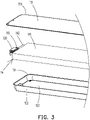
Figure 3 is a schematic diagram showing a partial exploded structure of a battery according to an exemplary embodiment. -
Figure 4 is a schematic diagram showing a partial structure of a battery apparatus according to an exemplary embodiment. -
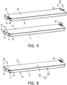
Figure 5 is a schematic diagram showing an exploded structure of a battery apparatus according to an exemplary embodiment. -
Figure 6 is a schematic diagram showing a structure of a first battery of a battery apparatus according to an exemplary embodiment. -
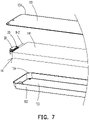
Figure 7 is a schematic diagram showing a partial exploded structure of a first battery of a battery apparatus according to an exemplary embodiment. -
Figure 8 is a schematic diagram showing a simplified structure of a battery apparatus according to a first exemplary embodiment. -
Figure 9 is a schematic diagram showing a simplified structure of a battery apparatus according to a second exemplary embodiment. -
Figure 10 is a schematic diagram showing a simplified structure of a battery apparatus according to a third exemplary embodiment. -
Figure 11 is a schematic diagram showing a simplified structure of a battery apparatus according to a fourth exemplary embodiment. -
Figure 12 is a schematic diagram showing a simplified structure of a battery apparatus according to a fifth exemplary embodiment. -
Figure 13 is a schematic diagram showing a simplified structure of a battery apparatus according to a sixth exemplary embodiment. -
Figure 14 is a schematic diagram showing a simplified structure of a battery apparatus according to a seventh exemplary embodiment. -
Figure 15 is a schematic diagram showing a simplified structure of a battery apparatus according to an eighth exemplary embodiment. - The technical solutions in the exemplary embodiments of the disclosure will be described clearly and explicitly in conjunction with the drawings in the exemplary embodiments of the disclosure. The description proposed herein is just the exemplary embodiments for the purpose of illustrations only, not intended to limit the scope of the disclosure, so it should be understood that and various modifications and variations could be made thereto without departing from the scope of the disclosure.
- In the description of the present disclosure, unless otherwise specifically defined and limited, the terms "first", "second" and the like are only used for illustrative purposes and are not to be construed as expressing or implying a relative importance. The term "plurality" is two or more. The term "and/or" includes any and all combinations of one or more of the associated listed items.
- In particular, a reference to "the" object or "a" and "an" object is intended to denote also one of a possible plurality of such objects. Unless otherwise defined or described, the terms "connect", "fix" should be broadly interpreted, for example, the term "connect" can be "fixedly connect", "detachably connect", "integrally connect", "electrically connect" or "signal connect". The term "connect" also can be "directly connect" or "indirectly connect via a medium". For the persons skilled in the art, the specific meanings of the abovementioned terms in the present disclosure can be understood according to the specific situation.
- Further, in the description of the present disclosure, it should be understood that spatially relative terms, such as "above", "below" "inside", "outside" and the like, are described based on orientations illustrated in the figures, but are not intended to limit the exemplary embodiments of the present disclosure.
- In the context, it should also be understood that when an element or features is provided "outside" or "inside" of another element(s), it can be directly provided "outside" or "inside" of the other element, or be indirectly provided "outside" or "inside" of the another element(s) by an intermediate element.
- An embodiment of the disclosure provides a battery. Referring to
Figures 1 to 3 , the battery includes: two oppositefirst surfaces 12 and foursecond surfaces 13 disposed around thefirst surfaces 12, an area of thefirst surface 12 larger than an area of thesecond surface 13; apole assembly 110, thepole assembly 110 disposed on thefirst surface 12; abusbar 120, thebusbar 120 bent into afirst segment 31 and asecond segment 32. Thefirst segment 31 is located at a side of thefirst surface 12 disposed with thepole assembly 110 and is connected to thepole assembly 110, thesecond segment 32 is parallel to or substantially parallel to asecond surface 13 and is used for electrically connecting a pole assembly of another battery. - The battery of an embodiment of the disclosure includes a
pole assembly 110 and abusbar 120. Thepole assembly 110 is disposed on thefirst surface 12 of the battery; that is, thepole assembly 110 is disposed on a large surface of the battery. Thefirst segment 31 of thebusbar 120 is connected to thepole assembly 110 and is directly opposite to thefirst surface 12, and thesecond segment 32 of thebusbar 120 is parallel to or substantially parallel to thesecond surface 13, so as to facilitate electrical connection with the pole assembly of another battery. - It should be noted that the
second segment 32 of thebusbar 120 may be connected to the busbar of another battery. In other words, thebusbar 120 is electrically connected to the pole assembly of another battery through the busbar of another battery, or thebusbar 120 may also be used for connecting other structures, such as cables. Alternatively, thebusbar 120 may be directly connected to the pole assembly of another battery. - The battery includes a
battery body 100, and thebattery body 100 includes two oppositefirst surfaces 12 and foursecond surfaces 13 disposed around thefirst surfaces 12. Thebattery body 100 has an approximately rectangular structure. In other words, while ignoring processing and manufacturing errors, thebattery body 100 may have a rectangular structure. - The two opposite
first surfaces 12 are large surfaces of thebattery body 100, and the foursecond surfaces 13 are small surfaces of thebattery body 100. The foursecond surfaces 13 include two pairs of small surfaces, namely a first pair of small surfaces extending along a length direction of thebattery body 100, and a second pair of small surfaces extending along a width direction of thebattery body 100. An area of the first pair of small surfaces is larger than an area of the second pair of small surfaces, but both are smaller than an area of the large surface. Thepole assembly 110 is disposed on thefirst surface 12 to ensure that thepole assembly 110 has a reliable supporting surface, so as to ensure the stability of thepole assembly 110. - In one embodiment, the orthographic projections of the
first segment 31 and thepole assembly 110 on afirst surface 12 at least partially overlap. That is, thefirst segment 31 and thepole assembly 110 may be directly connected, and the connection is extremely convenient. - Optionally, orthographic projections of the
first segment 31 and thepole assembly 110 on thefirst surface 12 do not overlap; that is, thefirst segment 31 and thepole assembly 110 may be connected by a metal connecting piece. - The
second segment 32 and thesecond surface 13 are parallel or substantially parallel, where the slight parallelism here actually ignores manufacturing errors and the like. Thesecond segment 32 may be parallel to the first pair of small surfaces extending along the length direction of thebattery body 100, or thesecond segment 32 may be parallel to the second pair of small surfaces extending along the width direction of thebattery body 100. - Optionally, the
first segment 31 and thefirst surface 12 are parallel or substantially parallel. In other words, when an end of thepole assembly 110 connected with thefirst segment 31 is parallel to afirst surface 12, thefirst segment 31 and thefirst surface 12 can be made parallel or substantially parallel, wherein an angle between thefirst segment 31 and thesecond segment 32 is a right angle. Of course, in some embodiments, thefirst segment 31 may be disposed obliquely to thefirst surface 12, wherein an angle between thefirst segment 31 and thesecond segment 32 may be an acute angle or an obtuse angle. - In one embodiment, the
first segment 31 and thesecond segment 32 are substantially perpendicular, so as to ensure the convenient connection of thebusbar 120 and that the battery disposition space can be effectively used. If various types of errors are ignored, thefirst segment 31 and thesecond segment 32 may be disposed vertically. Optionally, an included angle between thefirst segment 31 and thesecond segment 32 may be 80 degrees to 100 degrees. Further, the included angle between thefirst segment 31 and thesecond segment 32 may be 85 degrees to 95 degrees. - It should be noted that the fact that the
first segment 31 and thesecond segment 32 are substantially vertical has taken into account of specific process errors. That is, if the processing and manufacturing errors are ignored, the angle formed between thefirst segment 31 and thesecond segment 32 is a right angle. Optionally, the included angle between thefirst segment 31 and thesecond segment 32 may be 80 degrees to 100 degrees. Further, the included angle between thefirst segment 31 and thesecond segment 32 may be 85 degrees to 95 degrees. As shown inFigure 2 , when thefirst segment 31 transitions to thesecond segment 32 in an arc-shape, thefirst segment 31 and thesecond segment 32 here being substantially vertical is to emphasize the overall extension direction of the two; it is not specifically indicated that there must be a right-angle transition between thefirst segment 31 and thesecond segment 32. - In one embodiment, an orthographic projection of the
second segment 32 on a plane of thefirst surface 12 is located outside thefirst surface 12. In other words, one end of thefirst segment 31 needs to extend outside of the circumferential outer edge thebattery body 100, such that thesecond segment 32 is not located in a three-dimensional space where the circumferential outer edge of thebattery body 100 is located, thereby facilitating subsequent connection. - Optionally, at least part of an orthographic projection of the
second segment 32 on a plane where thefirst surface 12 is located is located inside thefirst surface 12. In other words, one end of thefirst segment 31 may not need to extend outside of the circumferential outer edge of anotherbattery body 100, such that thesecond segment 32 may be located in the three-dimensional space where the circumferential outer edge of thebattery body 100 is located. At this time, if thesecond segment 32 is connected to the pole assembly of another battery, thesecond segment 32 may directly extend to the pole assembly of the other battery for connection (that is, the pole assemblies of the two batteries may be directly opposite), or thesecond segment 32 may also be connected to the busbar of another battery. - It should be noted that the
busbar 120 is bent toward a direction away from thefirst surface 12; that is, thebusbar 120 increases the occupied space in a height direction of the battery. Alternatively, thebusbar 120 is bent toward a direction close to thefirst surface 12; that is, thebusbar 120 does not increase the occupied space in the height direction of the battery. - It should be noted that when the orthographic projection of the
second segment 32 on the plane where thefirst surface 12 is located is outside thefirst surface 12, no matter toward which direction thebusbar 120 is bent, the occupied space in a length direction of the battery will be increased, so as to facilitate the electrical connection between thebusbar 120 and external components. - In one embodiment, there are two
pole assemblies 110 and twobusbars 120. The twobusbars 120 are respectively connected to the twopole assemblies 110, such that the twopole assemblies 110 are electrically connected with other components through the twobusbars 120. - In one embodiment, as shown in
Figure 1 , the twopole assemblies 110 are disposed on the samefirst surface 12. Thebusbar 120 on onepole assembly 110 is bent toward a direction away from thefirst surface 12, and thebusbar 120 on theother pole assembly 110 is bent toward a direction close to thefirst surface 12, so as to facilitate convenient connection of the battery to external components. For example, when the battery is connected in series with another battery, the twobusbars 120 may be extended to two sides of the another battery, so as to facilitate the connection. - Optionally, the two
pole assemblies 110 may be respectively disposed on the twofirst surfaces 12. - In one embodiment, the
first segment 31 may be welded to thepole assembly 110 so as to ensure the stability of the connection. - In one embodiment, the thickness of the welded portion of the
first segment 31 and thepole assembly 110 is smaller than the thickness of thesecond segment 32, so as to facilitate convenient welding of thefirst segment 31 and thepole assembly 110. Specifically, it may be understood that portion which thefirst segment 31 connecting with thepole assembly 10 is thinned, such that thefirst segment 31 and thepole assembly 110 can be rapidly welded by the welding energy. - It should be noted that the
first segment 31 may be partially thinned. Of course, thefirst segment 31 may be overall thinned. - In one embodiment, the
busbar 120 and thepole assembly 110 may be an integrated structure. That is, thebusbar 120 and thepole assembly 110 are an integral structure, with relative simple structure and relatively high stability. The integral structure may be multiple independent parts that are fixedly connected after molding. In other words, thebusbar 120 and thepole assembly 110 have been connected before the battery assembly, instead of being connected during the battery assembly process. The integral structure may also be an integrally formed structure; that is, thebusbar 120 and thepole assembly 110 are integrally formed. - It should be noted that the
pole assembly 110 may be disposed protruding from thebattery body 100, or may be accommodated in thebattery body 100. In other words, a groove may be provided in thebattery body 100 for accommodating thepole assembly 110. Thepole assembly 110 and therecess 101 may be located on the twofirst surfaces 12 respectively, or both may be located on the samefirst surface 12. - In one embodiment, the
battery body 100 is provided with arecess 101, so as to accommodate the pole assembly of another battery during battery packing, such that the pole assembly does not occupy the space between the two batteries, and the distance between two adjacent batteries is reduced, thereby increasing the energy density of the battery packing. - It should be noted that the
recess 101 on thebattery body 100 is used for accommodating the pole assembly of another battery. That is, when two batteries are packed, the pole assembly protruding from the other battery may be accommodated in therecess 101. - In one embodiment, as shown in
Figure 3 , thebattery body 100 includes: acell 14, wherein thecell 14 is connected to thepole assembly 110; and ahousing 15, wherein thecell 14 is located in thehousing 15. Therecess 101 and thepole assembly 110 are both disposed on thehousing 15, which is not only convenient for assembly but also has a relatively simple structure. Thehousing 15 may be configured for the assembly of thepole assembly 110. - Optionally, the material of the
housing 15 may be stainless steel or aluminum, which has good corrosion resistance and sufficient strength. - In one embodiment, the thickness of the
housing 15 is uniform, which not only has strong structural stability, but also facilitates processing. - In one embodiment, as shown in
Figures 1 and3 , thehousing 15 includes: afirst housing 151; and asecond housing 152, wherein thesecond housing 152 is connected to thefirst housing 151 so as to close thecell 14. Thefirst housing 151 and thesecond housing 152 are disposed separately, which can facilitate the assembly of thecell 14 and convenient processing. - In one embodiment, the
recess 101 and thepole assembly 110 may both be disposed on thefirst housing 151, or therecess 101 and thepole assembly 110 may both be provided on thesecond housing 152. - In one embodiment, one of the
recess 101 and thepole assembly 110 is disposed on thefirst housing 151, and the other one of therecess 101 and thepole assembly 110 is disposed on thesecond housing 152, so as to ensure sufficient assembly space and ensure the strength of the structure. - Optionally, the
first housing 151 and thesecond housing 152 may both be formed with anaccommodating cavity 153. After thefirst housing 151 and thesecond housing 152 are butted, thecell 14 is located in a cavity formed by the twoaccommodating cavities 153. Depths of theaccommodating cavity 153 of thefirst housing 151 and thesecond housing 152 may be the same or different; no limitation is imposed here. - Optionally, the
first housing 151 is a flat plate. Thesecond housing 152 is formed with anaccommodating cavity 153, and thecell 14 is located in theaccommodating cavity 153. The disposition of the flat plate may facilitate subsequent connections and is less difficult to process. - Further, a protruding
edge 154 is disposed on the circumferential edge of thesecond housing 152, and thefirst housing 151 is welded to the protrudingedge 154, so as to ensure that thefirst housing 151 and thesecond housing 152 are reliably welded, thereby providing a connection stability. The disposition of the protrudingedge 154 is mainly to ensure that the welding area is increased, thereby improving the stability of the welding. - Optionally, when the
first housing 151 has anaccommodating cavity 153, the circumferential edge of thefirst housing 151 may also be disposed with a protrudingedge 154. As shown inFigure 3 , the protrudingedge 154 of thefirst housing 151 is welded to the protrudingedge 154 of thesecond housing 152. - It should be noted that the protruding
edge 154 may be understood as a flange, such as a flange formed by extending outward from the circumferential outer edge of a flat plate, or a flange formed by extending outward on a side wall of a structure having anaccommodating cavity 153, wherein the flange is substantially perpendicular to the side wall. For thefirst housing 151 and thesecond housing 152 being disposed with the protrudingedge 154 at the circumferential edges as described in the above-mentioned embodiments, reference may be made to such configuration, such that the protrudingedge 154 of thefirst housing 151 and the protrudingedge 154 of thesecond housing 152 may be directly opposite to each other so as to facilitate connection. - In one embodiment, as shown in
Figure 3 , thecell 14 includes a cellmain body 141 and atab 142, and thetab 142 extends from the length direction of the cellmain body 141, wherein thetab 142 is connected with thepole assembly 110. At this time, thepole assembly 110 may be disposed at the end of thebattery body 100 to facilitate the connection and can fully use the space along the length direction. Thetab 142 and thepole assembly 110 may be directly connected; that is, thetab 142 and thepole assembly 110 may be directly welded. Alternatively, thetab 142 and thepole assembly 110 may be connected by a metal adapter piece, and the specific connection method may be welding, or the use of riveting and the like; no limitation is imposed here. - It should be noted that the cell
main body 141 includes more than two electrode sheets, and thetab 142 includes more than two single-piece tabs. The single-piece tabs respectively extend from the corresponding electrode sheets, and the width of the single-piece tabs is smaller than the width of the electrode sheet. Multiple single-piece tabs are stacked to form atab 142, which is connected with thepole assembly 110, wherein thetab 142 may be welded to thepole assembly 110. The single-piece tabs are made of metal foil with good electrical and thermal conductivity, such as aluminum, copper, or nickel. - In some embodiments, there are two
pole assemblies 110; the twopole assemblies 110 are respectively a positive pole assembly and a negative pole assembly. There are also twotabs 142, and the twotabs 142 are a positive electrode and a negative electrode respectively. The positive pole assembly is connected with the positive tab, and the negative pole assembly is connected with the negative tab. - It should be noted that the
pole assembly 110 and thehousing 15 are disposed insulated from each other. For example, an insulating member may be configured for insulation between the two, or an insulating coating may be configured for insulation between the two. The insulation method may be based on actual needs; no limitation is imposed herein. - In one embodiment, a length of the battery is a, wherein 400mm≤a≤2500mm; a width of the battery is b, and the height of the battery is c, wherein 2b≤a≤SOb and/or 0.5c≤b≤20c.
- Further, 50mm≤b≤200mm, and 10mm≤c≤100mm.
- Further, 4b≤a≤25b, and/or 2c≤b≤10c.
- In the battery in the above embodiment, under the condition that sufficient energy density is ensured, a ratio of the length to the width of the battery is larger, and further, a ratio of the width to the height of the battery is larger.
- In one embodiment, a length of the battery is a, and a width of the battery is b, wherein 4b≤a≤7b. In other words, a ratio of the length to the width of the battery in the present embodiment is larger, thereby increasing the energy density of the battery and facilitating the subsequent formation of the battery module.
- In one embodiment, the height of the battery is c, wherein 3c≤b≤7c, and a ratio of the battery width to the height is relatively large, which also ensures formation of the battery module while ensuring sufficient energy density.
- Optionally, a length of the battery may be 500mm-1500mm, a width of the battery may be 80mm-150mm, and a height of the battery may be 15mm-25mm.
- It should be noted that the length of the battery is a size of the battery in a length direction, the width of the battery is a size of the battery in the width direction, and the height of the battery is a size of the battery in the height direction, namely a thickness of the battery.
- In one embodiment, the battery is a laminated battery, which not only is convenient for packing, but also may be processed to obtain a battery of longer length.
- Specifically, the
cell 14 is a laminated cell. Thecell 14 has a first electrode sheet laminated with each other, a second electrode sheet electrically opposite to the first electrode sheet, and a separator film disposed between the first electrode sheet and the second electrode sheet, such that multiple pairs of the first electrode sheet and the second electrode sheet are stacked to form a laminated cell. - Optionally, the battery may be a wound battery. In other words, the first electrode sheet, the second electrode sheet that is electrically opposite to the first electrode sheet, and the separator film disposed between the first electrode sheet and the second electrode sheet are wound, so as to obtain the wound battery.
- An embodiment of the disclosure further provides a battery apparatus. Referring to
Figures 4-7 , the battery apparatus includes a first battery 1 and asecond battery 2. The first battery 1 includes: two oppositefirst surfaces 12 and foursecond surfaces 13 disposed around thefirst surfaces 12, wherein an area of thefirst surface 12 is greater than an area of thesecond surface 13; afirst pole assembly 20, wherein thefirst pole assembly 20 is disposed on thefirst surface 12; and afirst busbar 30, wherein thefirst busbar 30 is bent into afirst segment 31 and asecond segment 32, thefirst segment 31 is located at a side of thefirst surface 12 where thefirst pole assembly 20 is disposed and is connected to thefirst pole assembly 20, and thesecond segment 32 is parallel to or substantially parallel to asecond surface 13. Thesecond battery 2 includes asecond pole assembly 50. The first battery 1 and thesecond battery 2 are disposed side by side, such that thesecond segment 32 is connected to thesecond pole assembly 50. - The battery apparatus of an embodiment of the disclosure includes the first battery 1 and the
second battery 2. By disposing thefirst pole assembly 20 of the first battery 1 on thefirst surface 12, that is, by disposing thefirst pole assembly 20 on the large surface of the first battery 1, thefirst segment 31 of thefirst busbar 30 is connected to thefirst pole assembly 20 and is directly opposite to thefirst surface 12, and thesecond segment 32 of thefirst busbar 30 and thesecond surface 13 are parallel or substantially parallel, so as to facilitate electrical connection with thesecond pole assembly 50 of thesecond battery 2. - It should be noted that the disposition of the first battery 1 and the
second battery 2 side by side means that the first battery 1 and thesecond battery 2 are packed together, wherein the first battery 1 and thesecond battery 2 may be stacked up and down, or left and right; no limitation is imposed herein. - It should be noted that the
second segment 32 of thefirst busbar 30 may be directly electrically connected to thesecond pole assembly 50 of thesecond battery 2. In other words, thesecond battery 2 does not need to be disposed with a busbar. For example, thesecond segment 32 of thefirst busbar 30 may be directly extended to thesecond pole assembly 50 for connection. When thefirst pole assembly 20 and thesecond pole assembly 50 are directly opposite, thesecond segment 32 may be directly extended to thesecond pole assembly 50. In such case, thesecond segment 32 does not need to be too long for the connection. - The first battery 1 includes a
first battery body 10, and thefirst battery body 10 includes two oppositefirst surfaces 12 and foursecond surfaces 13 disposed around the first surfaces 12. Thesecond battery 2 includes asecond battery body 40, and thesecond pole assembly 50 is disposed on thesecond battery body 40. Thesecond battery body 40 includes two oppositethird surfaces 42 and fourfourth surfaces 43 disposed around the third surfaces 42. In one embodiment, as shown inFigures 4 and5 , thesecond battery 2 further includes asecond busbar 60, and thesecond pole assembly 50 is connected to thesecond segment 32 through thesecond busbar 60 to facilitate the connection and facilitate the disposition of components, and effectively using the space of the battery apparatus. - In one embodiment, the
second battery 2 includes two oppositethird surfaces 42 and fourfourth surfaces 43 disposed around the third surfaces 42. An area of thethird surface 42 is larger than an area of thefourth surface 43. Thesecond pole assembly 50 is disposed on thethird surface 42; that is, thesecond pole assembly 50 is disposed on the large surface of thesecond battery 2, so as to ensure that thesecond pole assembly 50 has a reliable supporting surface, thereby ensuring the stability of thesecond pole assembly 50. - Further, as shown in
Figure 5 , thesecond busbar 60 is bent into athird segment 61 and afourth segment 62. Thethird segment 61 is located on the side of thethird surface 42 where thesecond pole assembly 50 is disposed, and is connected to thesecond pole assembly 50. Thefourth segment 62 is parallel to or substantially parallel to afourth surface 43 and is connected to thesecond segment 32. Both thefirst busbar 30 and thesecond busbar 60 are bent to facilitate the connection of thesecond segment 32 and thefourth segment 62, and facilitate the rapid connection between thesecond segment 32 and thefourth segment 62. - It should be noted that the
first surface 12 of the first battery 1 and thethird surface 42 of thesecond battery 2 are disposed oppositely. In other words, when the first battery 1 and thesecond battery 2 are packed, thefirst pole assembly 20 and thesecond pole assembly 50 may be disposed directly opposite to each other. At this time, thefirst busbar 30 and thesecond busbar 60 are directly opposite, and the distance between thesecond segment 32 and thefourth segment 62 is relatively short. - In one embodiment, the
first pole assembly 20 is disposed on onefirst surface 12 away from thesecond battery 2, and thesecond pole assembly 50 is disposed on onethird surface 42 close to the first battery 1. In other words, thefirst battery body 10 is actually clamped between thefirst pole assembly 20 and thesecond pole assembly 50. - Optionally, the
first pole assembly 20 is disposed on anotherfirst surface 12 close to thesecond battery 2, and thesecond pole assembly 50 is disposed on anotherthird surface 42 away from the first battery 1. That is, thesecond battery body 40 is actually clamped between thefirst pole assembly 20 and thesecond pole assembly 50. - In the foregoing embodiment, the
first pole assembly 20 and thesecond pole assembly 50 are not directly disposed opposite each other. Such design makes the disposition of the battery apparatus more reasonable, and the distance between thefirst busbar 30 and thesecond busbar 60 will not be too great. - Further, as shown in
Figures 5 and 6 , afirst recess 11 may be provided on thefirst battery body 10, and thefirst recess 11 and thefirst pole assembly 20 may be respectively located on the twofirst surfaces 12. At this time, thefirst recess 11 may be used for accommodating thesecond pole assembly 50 of thesecond battery 2. The projections of thefirst recess 11 and thefirst pole assembly 20 along a direction perpendicular to thefirst battery body 10 at least partially overlap, such that when the first battery 1 and thesecond battery 2 are packed, the first battery 1 and thesecond battery 2 may be aligned with each other, so as to ensure that thesecond pole assembly 50 may be reliably accommodated in thefirst recess 11. - Optionally, as shown in
Figure 5 , thesecond battery body 40 may also be provided with a second recess 41 thereon. In such case, the second recess 41 may be used for accommodating a pole assembly of a third battery; no limitation is imposed here. The emphasis is that if the pole assembly of the battery is disposed protruding from the battery body, a recess may be provided on another battery so as to accommodate the adjacent pole assembly, such that the distance between the batteries is minimized, thereby increasing the energy density of the battery apparatus. - In one embodiment, an orthographic projection of the
second segment 32 on a plane of thefirst surface 12 is located outside thefirst surface 12, and an orthographic projection of thefourth segment 62 on a plane where thethird surface 42 is located is outside on thethird surface 42. In other words, thesecond segment 32 and thefourth segment 62 are connected outside the circumferential outer edge of the battery, so as not to occupy the space between the batteries, thereby ensuring the energy density of the battery and facilitating the connection. - Optionally, the
first busbar 30 is bent toward a direction close to thefirst surface 12, and thesecond busbar 60 is bent toward a direction close to thethird surface 42. Thefourth segment 62 and thesecond segment 32 are connected by anadapter piece 70; that is, thefourth segment 62 is connected with theadapter piece 70, and thesecond segment 32 is connected with theadapter piece 70, as shown inFigure 8 . Alternatively, thefourth segment 62 and thesecond segment 32 may be directly welded, as shown inFigure 9 . - Optionally, the
first busbar 30 is bent toward a direction away from thefirst surface 12, and thesecond busbar 60 is bent toward a direction away from thethird surface 42. Thefourth segment 62 and thesecond segment 32 are connected by anadapter piece 70. That is, thefourth segment 62 is connected with theadapter piece 70, and thesecond segment 32 is connected with theadapter piece 70, as shown inFigure 10 . Alternatively, thefourth segment 62 and thesecond segment 32 are directly welded, as shown inFigure 11 . - Optionally, the
first busbar 30 is bent toward a direction close to thefirst surface 12, and thesecond busbar 60 is bent toward a direction away from thethird surface 42; in other words, the distance between thefourth segment 62 and thesecond segment 32 reaches the minimum. Thefourth segment 62 and thesecond segment 32 are connected by theadapter piece 70; that is, thefourth segment 62 is connected with theadapter piece 70, and thesecond segment 32 is connected with theadapter piece 70. Alternatively, thefourth segment 62 and thesecond segment 32 are directly welded. As shown inFigure 12 , thefourth segment 62 and thesecond segment 32 may also be disposed overlapped. Alternatively, thefourth segment 62 and thesecond segment 32 may be directly butted; that is, the end face of thefourth segment 62 and the end face of thesecond segment 32 are directly butted, as shown inFigure 13 , and thefirst busbar 30 and thesecond busbar 60 form a U-shaped structure. - Optionally, the
first busbar 30 is bent toward a direction away from thefirst surface 12, and thesecond busbar 60 is bent toward a direction close to thethird surface 42; in other words, the distance between thefourth segment 62 and thesecond segment 32 reaches the maximum. Thefourth segment 62 and thesecond segment 32 are connected by theadapter piece 70; that is, thefourth segment 62 is connected with theadapter piece 70, and thesecond segment 32 is connected with theadapter piece 70. - It should be noted that the connection mode of the
fourth segment 62 and thesecond segment 32 is not limited here, and may be selected according to actual needs. In the selection of theadapter piece 70, theadapter piece 70 is a metal piece, which is not only easy to weld, but also the reliability of welding is strong. - It should be noted that for the connection of the
fourth segment 62 and thesecond segment 32, thefourth segment 62 and thesecond segment 32 may be directly butted. Of course, thefourth segment 62 and thesecond segment 32 may also be disposed overlapped; no limitation is imposed herein. - In one embodiment, the
fourth segment 62 and thesecond segment 32 are disposed overlapped, and thefourth segment 62 is located outside thesecond segment 32. A thickness of a welded portion of thefourth segment 62 and thesecond segment 32 is smaller than a thickness of thethird segment 61, or a thickness of thesecond busbar 60 is smaller than a thickness of thefirst busbar 30, so as to facilitate convenient welding between thefourth segment 62 and thesecond segment 32. Specifically, it may be understood that portion which thefourth segment 62 connecting with thesecond segment 32 is thinned, such that thefourth segment 62 and thesecond segment 32 can be rapidly welded by the welding energy. - It should be noted that the
second busbar 60 may partially thin only thefourth segment 62, as shown inFigure 15 . Of course, thefourth segment 62 may also be overall thinned. Needless to say, an overall thickness of thesecond busbar 60 may be smaller than the thickness of thefirst busbar 30, which is similar to the overall thinning of thesecond busbar 60, as shown inFigure 14 . - Optionally, the
fourth segment 62 and thesecond segment 32 are disposed overlapped, and thefourth segment 62 is located inside thesecond segment 32. A thickness of a welded portion between thesecond segment 32 and thefourth segment 62 is smaller than the thickness of thefirst segment 31, or a thickness of thefirst busbar 30 is smaller than the thickness of thesecond busbar 60, so as to facilitate convenient welding between thesecond segment 32 and thefourth segment 62. Specifically, it may be understood that portion which thefourth segment 62 connecting with thesecond segment 32 is thinned, such that thesecond segment 32 and thefourth segment 62 can be rapidly welded by the welding energy. - It should be noted that the
first busbar 30 may partially thin only thesecond segment 32. Of course, thesecond segment 32 may also be overall thinned. Needless to say, an overall thickness of thefirst busbar 30 may be smaller than the thickness of thesecond busbar 60, which is similar to the overall thinning of thefirst busbar 30. - Optionally, the
first battery body 10 has an approximately rectangular structure. In other words, while ignoring processing and manufacturing errors, thefirst battery body 10 may have a rectangular structure. Correspondingly, thesecond battery body 40 has an approximately rectangular structure. - There are two
first pole assemblies 20 and twofirst busbars 30, and the twofirst busbars 30 are respectively connected to the twofirst pole assemblies 20. There are twosecond pole assemblies 50 and twosecond busbars 60, and the twosecond busbars 60 are respectively connected to the twosecond pole assemblies 50. The first battery 1 and thesecond battery 2 may be connected in series. In such case, onefirst pole assembly 20 is connected to onesecond pole assembly 50, and the otherfirst pole assembly 20 is connected to the third battery; correspondingly, the othersecond pole assembly 50 may be connected to a fourth battery. The first battery 1 and thesecond battery 2 may be connected in parallel. In such case, onefirst pole assembly 20 is connected to onesecond pole assembly 50, and the otherfirst pole assembly 20 is connected to the othersecond pole assembly 50. The connection relationship between the batteries of the battery apparatus is not limited here, connection in series and in parallel may be selected according to actual needs. - In one embodiment, orthographic projections of the
first segment 31 and thefirst pole assembly 20 on afirst surface 12 at least partially overlap. In other words, thefirst segment 31 and thefirst pole assembly 20 may be directly connected, and the connection is very convenient. - The orthographic projections of the
third segment 61 and thesecond pole assembly 50 on athird surface 42 at least partially overlap. That is, thethird segment 61 and thesecond pole assembly 50 may be directly connected, and the connection is very convenient. - Optionally, orthographic projections of the
first segment 31 and thefirst pole assembly 20 on onefirst surface 12 do not overlap. That is, thefirst segment 31 and thepole assembly 110 may be connected by a metal connecting piece. - Orthographic projections of the
third segment 61 and thesecond pole assembly 50 on athird surface 42 do not overlap. That is, thethird segment 61 and thesecond pole assembly 50 may be connected by a metal connecting piece. - In one embodiment, as shown in
Figure 10 , thefirst battery body 10 includes: thecell 14, wherein thecell 14 is connected to thefirst pole assembly 20; and thehousing 15, wherein thecell 14 is located in thehousing 15. Thefirst recess 11 and thefirst pole assembly 20 are both disposed on thehousing 15, which is not only convenient for assembly but also has a relatively simple structure, so thehousing 15 may be configured for the assembly of thefirst pole assembly 20. - In one embodiment, as shown in
Figures 6 and7 , thehousing 15 includes: thefirst housing 151; and thesecond housing 152, wherein thesecond housing 152 is connected to thefirst housing 151, so as to close thecell 14. Thefirst housing 151 and thesecond housing 152 are disposed separately, which can facilitate the assembly of thecell 14 and the convenient processing. - Optionally, the
first housing 151 and thesecond housing 152 may both be formed with anaccommodating cavity 153. After thefirst housing 151 and thesecond housing 152 are butted, thecell 14 is located in the cavity formed by the twoaccommodating cavities 153. Depths of theaccommodating cavity 153 of thefirst housing 151 and thesecond housing 152 may be the same or different; no limitation is imposed here. - Optionally, the
first housing 151 is a flat plate, thesecond housing 152 is formed with theaccommodating cavity 153, and thebattery cell 14 is located in theaccommodating cavity 153. The disposition of the flat plate may facilitate subsequent connections and is less difficult to process. - Further, a protruding
edge 154 is disposed on the circumferential edge of thesecond housing 152. Thefirst housing 151 is welded to the protrudingedge 154, so as to ensure that thefirst housing 151 and thesecond housing 152 are reliably welded, thereby providing a connection stability. The disposition of the protrudingedge 154 is mainly to ensure that the welding area is increased, thereby improving the stability of the welding. - Optionally, when the
first housing 151 has theaccommodating cavity 153, the circumferential edge of thefirst housing 151 may also be disposed with a protrudingedge 154, and the protrudingedge 154 of thefirst housing 151 and the protrudingedge 154 of thesecond housing 152 are welded. - In one embodiment, as shown in
Figure 7 , thecell 14 includes the cellmain body 141 and thetab 142. Thetab 142 extends from the length direction of the cellmain body 141, wherein thetab 142 is connected to thefirst pole assembly 20. At this time, thefirst pole assembly 20 may be disposed at the end of thefirst battery body 10 to facilitate the connection and can fully use the space along the length direction. - It should be noted that for the structure and disposition of the
second battery body 40 and thesecond pole assembly 50, reference may be made to the above-mentionedfirst pole assembly 20 and thefirst battery body 10; details which will not be repeated here. In some embodiments, the first battery 1 and thesecond battery 2 may have exactly the same structure. - It should be noted that, as shown in
Figures 8-15 , the busbar (thefirst busbar 30 and/or the second busbar 60) and the battery side (thesecond surface 13 and/or the fourth surface 43) are disposed at intervals, such that reliable electrical isolation is ensured, and that the tooling may be inserted into the gap for fixing during welding, for convenient welding. Optionally, there may be direct contact between the busbar and the side of the battery; that is, the two may be insulated by a coating. - In an embodiment, the battery apparatus may further include a third battery. The third battery may be one or at least two, and the structure of the third battery is similar or completely the same as the first battery 1 and the
second battery 2; details will not be repeated here. - In one embodiment, a length of the first battery 1 is d, wherein 400mm≤d≤2500mm; a width of the first battery 1 is e, and a height of the first battery 1 is f, wherein 2e≤d≤50e and/or 0.5 f≤e≤20f.
- Optionally, a length of the
second battery 2 is d, wherein 400mm≤d≤2500mm; a width of thesecond battery 2 is e, and a height of thesecond battery 2 is f, wherein 2e≤d≤50e and/or 0.5f≤e≤20f. - In one embodiment, the length of the first battery 1 is d, the width of the first battery 1 is e, and the height of the first battery 1 is f, 4e≤d≤7e, and/or, 3f≤e≤7f.
- Optionally, a length of the
second battery 2 is d, a width of thesecond battery 2 is e, and a height of thesecond battery 2 is f, wherein 4e≤d≤7e and/or 3f≤e≤7f. - In one embodiment, the first battery 1 is a laminated battery, and the
second battery 2 is a laminated battery, which not only is convenient for packing, but also may be processed to obtain a longer-length battery. - It should be noted that, for the structures of the first battery 1 and the
second battery 2 in this embodiment, reference may be made to the specific structure of the battery in the foregoing embodiment; details will not be repeated here. - It should be noted that the above-mentioned battery apparatus may be a battery module or a battery pack.
- Optionally, the battery pack includes at least two battery apparatuses, the battery pack may also include a case, and the at least two battery apparatuses are disposed in the case. Alternatively, multiple batteries may be directly disposed in the case; that is, the packing process is cancelled.
- Other embodiments of the disclosure will be apparent to those skilled in the art from consideration of the specification and practice of the disclosure disclosed herein. The disclosure is intended to cover any variations, uses or adaptations of the disclosure. These variations, uses, or adaptations follow the general principles of the disclosure and include common general knowledge or conventional technical means in the art that are not disclosed in the present disclosure. The specification and embodiments are illustrative, and the real scope and spirit of the present disclosure is defined by the appended claims.
- It should be understood that the disclosure is not limited to the precise structures that have been described above and shown in the drawings, and various modifications and variations can be made without departing from the scope thereof. The scope of the disclosure is limited only by the appended claims.
Claims (21)
- A battery, comprising:two opposite first surfaces (12) and four second surfaces (13) disposed around the first surfaces (12), an area of the first surface larger (12) than an area of the second surface (13);a pole assembly (110), the pole assembly (110) disposed on the first surface (12); anda busbar (120), the busbar (120) bent into a first segment (31) and a second segment (32), wherein the first segment (31) is located at a side of the first surface (12) disposed with the pole assembly (110) and is connected to the pole assembly (110), and the second segment (32) is parallel to or substantially parallel to one of the second surfaces (13) and is used for electrically connecting a pole assembly of another battery.
- The battery according to claim 1, wherein the first segment (31) and the second segment (32) are substantially perpendicular.
- The battery according to claim 1, wherein an orthographic projection of the second segment (32) on a plane where the first surface (12) is located is located outside the first surface (12); and
the busbar (120) is bent toward a direction away from the first surface (12); or, the busbar (120) is bent toward a direction close to the first surface (12). - The battery according to claim 3, wherein a number of the pole assemblies (110) is two, and a number of the busbars (120) is two; the two busbars (120) are connected to the two pole assemblies (110) respectively.
- The battery according to claim 4, wherein the two pole assemblies (110) are disposed on the same first surface (12); and
the busbar (120) on one of the pole assemblies (110) is bent toward a direction away from the first surface (12), and the busbar (120) on the other one of the pole assemblies (110) is bent toward a direction close to the first surface (12). - The battery according to claim 1, wherein the first segment (31) is welded to the pole assembly (110).
- The battery according to claim 6, wherein a thickness of a portion of the first segment (31) welded on the pole assembly (110) is smaller than a thickness of the second segment (32).
- The battery according to claim 1, wherein the busbar (120) and the pole assembly (110) are integrally formed.
- The battery according to any one of claims 1 to 8, wherein orthographic projections of the first segment (31) and the pole assembly (110) on one of the first surfaces (12) at least partially overlap.
- The battery according to any one of claims 1 to 8, wherein a length of the battery is a, a width of the battery is b, and a height of the battery is c, wherein 2b≤a≤50b, and/or 0.5 c≤b≤20c; and
400mm≤a≤2500mm. - A battery apparatus, comprising a first battery (1) and a second battery (2), the first battery (1) comprising:two opposite first surfaces (12) and four second surfaces (14) disposed around the first surfaces (12), an area of the first surface (12) larger than an area of the second surface (14);a first pole assembly (20), the first pole assembly (20) disposed on the first surface (12);a first busbar (30), the first busbar (30) bent into a first segment (31) and a second segment (32), wherein the first segment (31) is located at a side of the first surface (12) disposed with the first pole assembly (20) and is connected to the first pole assembly (20), and the second segment (32) slightly is parallel the one of the second surfaces (13);the second battery (2), comprising a second pole assembly (50); andthe first battery (1), disposed side by side with the second battery (2), such that the second segment (32) is connected to the second pole assembly (50).
- The battery apparatus according to claim 11, wherein the second battery (2) further comprises a second busbar (60), and the second pole assembly (50) is connected to the second segment (32) through the second busbar (60).
- The battery apparatus according to claim 12, wherein the second battery (2) further comprises two opposite third surfaces (42) and four fourth surfaces (43) surrounding the third surfaces (42), wherein an area of the third surface (42) is greater than an area of the fourth surface (43), and the second pole assembly (50) is disposed on the third surface (42); and
the second busbar (60) is bent into a third segment (61) and a fourth segment (62), wherein the third segment (61) is located at a side of the third surface (42) disposed with the second pole assembly (50) and is connected to the second pole assembly (50), and the fourth segment (62) is parallel to or substantially parallel to one of the fourth surfaces (43) and connected to the second segment (32). - The battery apparatus according to claim 13, wherein the first pole assembly (20) is disposed on one of the first surfaces (12) away from the second battery (2), the second pole assembly (50) is disposed on one of the third surfaces (42) close to the first battery (1); or
the first pole assembly (20) is disposed on the other one of the first surfaces (12) close to the second battery (2), and the second pole assembly (50) is disposed on the other one of the third surfaces (42) away from the first battery (1). - The battery apparatus according to claim 14, wherein an orthographic projection of the second segment (32) on a plane where the first surface (12) is located is located outside the first surface (12), and an orthographic projection of the fourth segment (62) on a plane where the third surface (42) is located is located outside the third surface (42); and
the first busbar (30) is bent toward a direction away from the first surface (12) and the second busbar (60) is bent toward a direction away from the third surface (42); or, the first busbar (30) is bent toward the direction away from the first surface (12) and the second busbar (60) is bent toward a direction close to the third surface(42); or, the first busbar (30) is bent toward a direction close to the first surface (12) and the second busbar (60) is bent toward the direction away from the third surface (42); or, the first busbar (30) is bent toward the direction close to the first surface (12) and the second busbar (60) is bent toward the direction close to the third surface (42). - The battery apparatus according to claim 15, wherein the fourth segment (62) and the second segment (32) are directly welded; or
the battery apparatus further comprises an adapter piece (70), and the fourth segment (62) and the second segment (32) are both welded to the adapter piece (70). - The battery apparatus according to claim 16, wherein the fourth segment (62) and the second segment (32) are disposed overlapped, and the fourth segment (62) is located outside the second segment (32); a thickness of a portion of the fourth segment (62) welded on the second segment (32) is smaller than a thickness of the third segment (61), or a thickness of the second busbar (60) is smaller than a thickness of the first busbar (30).
- The battery apparatus according to claim 15, wherein the fourth segment (62) and the second segment (32) are disposed overlapped, the fourth segment (62) is located inside the second segment (32); a thickness of the welded portion of the second segment (32) and the fourth segment (62) is smaller than a thickness of the first segment (31), or a thickness of the first busbar (30) is smaller than a thickness of the second busbar (60).
- The battery apparatus according to claim 13, wherein an end surface of the fourth segment (42) and an end surface of the second segment (32) are directly butted.
- The battery apparatus according to claim 13, wherein an orthographic projection of the first segment (31) and the first pole assembly (20) on one of the first surfaces (12) at least partially overlap, and orthographic projections of the third segment (61) and the second pole assembly (50) on one of the third surfaces (42) at least partially overlap.
- The battery apparatus according to claim 11, wherein a length of at least one of the first battery (1) and the second battery (2) is d, a width of at least one of the first battery (1) and the second battery (2) is e, a height of at least one of the first battery (1) and the second battery (2) is f, wherein 2e≤d≤50e, and/or 0.5f≤e≤20f; and
400mm≤d≤2500mm.
Applications Claiming Priority (1)
| Application Number | Priority Date | Filing Date | Title |
|---|---|---|---|
| CN202110528370.2A CN115347333B (en) | 2021-05-14 | 2021-05-14 | Batteries and battery packs |
Publications (1)
| Publication Number | Publication Date |
|---|---|
| EP4089804A1 true EP4089804A1 (en) | 2022-11-16 |
Family
ID=77042777
Family Applications (1)
| Application Number | Title | Priority Date | Filing Date |
|---|---|---|---|
| EP21187328.6A Pending EP4089804A1 (en) | 2021-05-14 | 2021-07-23 | Battery and battery apparatus |
Country Status (3)
| Country | Link |
|---|---|
| US (1) | US11916255B2 (en) |
| EP (1) | EP4089804A1 (en) |
| CN (1) | CN115347333B (en) |
Cited By (2)
| Publication number | Priority date | Publication date | Assignee | Title |
|---|---|---|---|---|
| EP4270608A4 (en) * | 2021-10-22 | 2025-01-15 | Contemporary Amperex Technology (Hong Kong) Limited | BATTERY CELL, BATTERY AND ELECTRICAL DEVICE |
| US12249723B2 (en) | 2021-10-22 | 2025-03-11 | Contemporary Amperex Technology (Hong Kong) Limited | Battery, electric device, and method and device for preparing battery cell |
Families Citing this family (3)
| Publication number | Priority date | Publication date | Assignee | Title |
|---|---|---|---|---|
| CN115732866A (en) * | 2022-12-01 | 2023-03-03 | 中创新航科技股份有限公司 | Battery and battery pack |
| CN222654173U (en) * | 2024-05-14 | 2025-03-21 | 比亚迪股份有限公司 | Battery shell, battery pack and electric equipment |
| CN118676547B (en) * | 2024-08-21 | 2025-01-24 | 宁德时代新能源科技股份有限公司 | Battery cells, battery devices, power consumption devices and energy storage devices |
Citations (3)
| Publication number | Priority date | Publication date | Assignee | Title |
|---|---|---|---|---|
| US20150079448A1 (en) * | 2013-09-17 | 2015-03-19 | Kabushiki Kaisha Toshiba | Nonaqueous electrolyte battery |
| EP3309856A1 (en) * | 2015-06-12 | 2018-04-18 | Kabushiki Kaisha Toshiba | Battery and assembled battery |
| EP3467905A1 (en) * | 2016-05-30 | 2019-04-10 | Kabushiki Kaisha Toshiba | Battery pack and battery cell |
Family Cites Families (9)
| Publication number | Priority date | Publication date | Assignee | Title |
|---|---|---|---|---|
| JP2003282045A (en) * | 2002-03-26 | 2003-10-03 | Sanyo Gs Soft Energy Co Ltd | Battery |
| JP2006185733A (en) * | 2004-12-27 | 2006-07-13 | Nissan Motor Co Ltd | Manufacturing method of assembled battery and assembled battery manufactured by the method |
| JP5957651B2 (en) * | 2013-06-07 | 2016-07-27 | パナソニックIpマネジメント株式会社 | Assembled battery |
| KR102263198B1 (en) * | 2014-01-28 | 2021-06-10 | 삼성에스디아이 주식회사 | Battery Pack |
| JP2016046023A (en) * | 2014-08-21 | 2016-04-04 | 日産自動車株式会社 | Battery pack |
| CN205723728U (en) * | 2016-05-03 | 2016-11-23 | 北京新能源汽车股份有限公司 | Battery pack and battery pack having the same |
| US10854866B2 (en) * | 2019-04-08 | 2020-12-01 | H55 Sa | Power supply storage and fire management in electrically-driven aircraft |
| CN209963326U (en) * | 2019-07-05 | 2020-01-17 | 江苏时代新能源科技有限公司 | Connecting assembly and battery pack |
| CN214589168U (en) * | 2021-05-14 | 2021-11-02 | 中航锂电科技有限公司 | Battery and battery pack |
-
2021
- 2021-05-14 CN CN202110528370.2A patent/CN115347333B/en active Active
- 2021-07-22 US US17/382,365 patent/US11916255B2/en active Active
- 2021-07-23 EP EP21187328.6A patent/EP4089804A1/en active Pending
Patent Citations (3)
| Publication number | Priority date | Publication date | Assignee | Title |
|---|---|---|---|---|
| US20150079448A1 (en) * | 2013-09-17 | 2015-03-19 | Kabushiki Kaisha Toshiba | Nonaqueous electrolyte battery |
| EP3309856A1 (en) * | 2015-06-12 | 2018-04-18 | Kabushiki Kaisha Toshiba | Battery and assembled battery |
| EP3467905A1 (en) * | 2016-05-30 | 2019-04-10 | Kabushiki Kaisha Toshiba | Battery pack and battery cell |
Cited By (2)
| Publication number | Priority date | Publication date | Assignee | Title |
|---|---|---|---|---|
| EP4270608A4 (en) * | 2021-10-22 | 2025-01-15 | Contemporary Amperex Technology (Hong Kong) Limited | BATTERY CELL, BATTERY AND ELECTRICAL DEVICE |
| US12249723B2 (en) | 2021-10-22 | 2025-03-11 | Contemporary Amperex Technology (Hong Kong) Limited | Battery, electric device, and method and device for preparing battery cell |
Also Published As
| Publication number | Publication date |
|---|---|
| CN115347333A (en) | 2022-11-15 |
| US11916255B2 (en) | 2024-02-27 |
| CN115347333B (en) | 2026-01-02 |
| US20220367979A1 (en) | 2022-11-17 |
Similar Documents
| Publication | Publication Date | Title |
|---|---|---|
| US11916255B2 (en) | Battery and battery apparatus | |
| CN214589168U (en) | Battery and battery pack | |
| CN102738428B (en) | Secondary cell | |
| EP2528143B1 (en) | Power storage element provided with a current collector, and method of manufacturing current collector | |
| EP3490034B1 (en) | Electrode member, electrode assembly and rechargeable battery | |
| US20130071728A1 (en) | Secondary Battery | |
| CN103597630B (en) | Prismatic cell | |
| EP4089775A1 (en) | Battery assembly and assembling method of battery assembly | |
| CN209401723U (en) | Battery module, secondary battery and top cover assembly thereof | |
| EP3799182B1 (en) | Secondary battery, battery pack and electric device | |
| CN115706297B (en) | Batteries and batteries | |
| US20220238890A1 (en) | Secondary battery and manufacturing method thereof, battery module, and apparatus | |
| JP2009087613A (en) | Square battery | |
| CN115332696A (en) | Battery and electric equipment | |
| CN111799429B (en) | Pouch battery and method for assembling pouch battery | |
| JP5633031B2 (en) | Secondary battery and method for manufacturing secondary battery | |
| CN115347280A (en) | Batteries, batteries and packs | |
| CN220553565U (en) | Battery cell and battery device | |
| CN220553576U (en) | Single cells and battery packs | |
| CN110176565A (en) | Battery cell module and assembling method thereof | |
| JP2018032523A (en) | Insulation member and secondary battery | |
| CN213878218U (en) | Insulating bi-pass casing and single battery | |
| US20230137433A1 (en) | Electrical storage module | |
| CN219575873U (en) | Battery assembly | |
| CN218498292U (en) | Battery with a battery cell |
Legal Events
| Date | Code | Title | Description |
|---|---|---|---|
| PUAI | Public reference made under article 153(3) epc to a published international application that has entered the european phase |
Free format text: ORIGINAL CODE: 0009012 |
|
| STAA | Information on the status of an ep patent application or granted ep patent |
Free format text: STATUS: REQUEST FOR EXAMINATION WAS MADE |
|
| 17P | Request for examination filed |
Effective date: 20210723 |
|
| AK | Designated contracting states |
Kind code of ref document: A1 Designated state(s): AL AT BE BG CH CY CZ DE DK EE ES FI FR GB GR HR HU IE IS IT LI LT LU LV MC MK MT NL NO PL PT RO RS SE SI SK SM TR |