EP4089803A1 - Battery manufacturing method and battery - Google Patents
Battery manufacturing method and battery Download PDFInfo
- Publication number
- EP4089803A1 EP4089803A1 EP21188374.9A EP21188374A EP4089803A1 EP 4089803 A1 EP4089803 A1 EP 4089803A1 EP 21188374 A EP21188374 A EP 21188374A EP 4089803 A1 EP4089803 A1 EP 4089803A1
- Authority
- EP
- European Patent Office
- Prior art keywords
- flange
- housing
- reinforcing part
- battery
- welding
- Prior art date
- Legal status (The legal status is an assumption and is not a legal conclusion. Google has not performed a legal analysis and makes no representation as to the accuracy of the status listed.)
- Pending
Links
Images


Classifications
-
- H—ELECTRICITY
- H01—ELECTRIC ELEMENTS
- H01M—PROCESSES OR MEANS, e.g. BATTERIES, FOR THE DIRECT CONVERSION OF CHEMICAL ENERGY INTO ELECTRICAL ENERGY
- H01M6/00—Primary cells; Manufacture thereof
-
- H—ELECTRICITY
- H01—ELECTRIC ELEMENTS
- H01M—PROCESSES OR MEANS, e.g. BATTERIES, FOR THE DIRECT CONVERSION OF CHEMICAL ENERGY INTO ELECTRICAL ENERGY
- H01M50/00—Constructional details or processes of manufacture of the non-active parts of electrochemical cells other than fuel cells, e.g. hybrid cells
- H01M50/10—Primary casings; Jackets or wrappings
- H01M50/147—Lids or covers
- H01M50/166—Lids or covers characterised by the methods of assembling casings with lids
- H01M50/169—Lids or covers characterised by the methods of assembling casings with lids by welding, brazing or soldering
-
- H—ELECTRICITY
- H01—ELECTRIC ELEMENTS
- H01M—PROCESSES OR MEANS, e.g. BATTERIES, FOR THE DIRECT CONVERSION OF CHEMICAL ENERGY INTO ELECTRICAL ENERGY
- H01M50/00—Constructional details or processes of manufacture of the non-active parts of electrochemical cells other than fuel cells, e.g. hybrid cells
- H01M50/10—Primary casings; Jackets or wrappings
- H01M50/102—Primary casings; Jackets or wrappings characterised by their shape or physical structure
-
- B—PERFORMING OPERATIONS; TRANSPORTING
- B23—MACHINE TOOLS; METAL-WORKING NOT OTHERWISE PROVIDED FOR
- B23K—SOLDERING OR UNSOLDERING; WELDING; CLADDING OR PLATING BY SOLDERING OR WELDING; CUTTING BY APPLYING HEAT LOCALLY, e.g. FLAME CUTTING; WORKING BY LASER BEAM
- B23K26/00—Working by laser beam, e.g. welding, cutting or boring
- B23K26/20—Bonding
- B23K26/21—Bonding by welding
- B23K26/24—Seam welding
- B23K26/244—Overlap seam welding
-
- B—PERFORMING OPERATIONS; TRANSPORTING
- B23—MACHINE TOOLS; METAL-WORKING NOT OTHERWISE PROVIDED FOR
- B23K—SOLDERING OR UNSOLDERING; WELDING; CLADDING OR PLATING BY SOLDERING OR WELDING; CUTTING BY APPLYING HEAT LOCALLY, e.g. FLAME CUTTING; WORKING BY LASER BEAM
- B23K26/00—Working by laser beam, e.g. welding, cutting or boring
- B23K26/36—Removing material
- B23K26/38—Removing material by boring or cutting
-
- B—PERFORMING OPERATIONS; TRANSPORTING
- B23—MACHINE TOOLS; METAL-WORKING NOT OTHERWISE PROVIDED FOR
- B23K—SOLDERING OR UNSOLDERING; WELDING; CLADDING OR PLATING BY SOLDERING OR WELDING; CUTTING BY APPLYING HEAT LOCALLY, e.g. FLAME CUTTING; WORKING BY LASER BEAM
- B23K31/00—Processes relevant to this subclass, specially adapted for particular articles or purposes, but not covered by any single one of main groups B23K1/00 - B23K28/00
-
- H—ELECTRICITY
- H01—ELECTRIC ELEMENTS
- H01M—PROCESSES OR MEANS, e.g. BATTERIES, FOR THE DIRECT CONVERSION OF CHEMICAL ENERGY INTO ELECTRICAL ENERGY
- H01M10/00—Secondary cells; Manufacture thereof
- H01M10/04—Construction or manufacture in general
-
- H—ELECTRICITY
- H01—ELECTRIC ELEMENTS
- H01M—PROCESSES OR MEANS, e.g. BATTERIES, FOR THE DIRECT CONVERSION OF CHEMICAL ENERGY INTO ELECTRICAL ENERGY
- H01M10/00—Secondary cells; Manufacture thereof
- H01M10/04—Construction or manufacture in general
- H01M10/0431—Cells with wound or folded electrodes
-
- H—ELECTRICITY
- H01—ELECTRIC ELEMENTS
- H01M—PROCESSES OR MEANS, e.g. BATTERIES, FOR THE DIRECT CONVERSION OF CHEMICAL ENERGY INTO ELECTRICAL ENERGY
- H01M50/00—Constructional details or processes of manufacture of the non-active parts of electrochemical cells other than fuel cells, e.g. hybrid cells
- H01M50/10—Primary casings; Jackets or wrappings
- H01M50/147—Lids or covers
- H01M50/148—Lids or covers characterised by their shape
-
- B—PERFORMING OPERATIONS; TRANSPORTING
- B23—MACHINE TOOLS; METAL-WORKING NOT OTHERWISE PROVIDED FOR
- B23K—SOLDERING OR UNSOLDERING; WELDING; CLADDING OR PLATING BY SOLDERING OR WELDING; CUTTING BY APPLYING HEAT LOCALLY, e.g. FLAME CUTTING; WORKING BY LASER BEAM
- B23K2101/00—Articles made by soldering, welding or cutting
- B23K2101/36—Electric or electronic devices
-
- H—ELECTRICITY
- H01—ELECTRIC ELEMENTS
- H01M—PROCESSES OR MEANS, e.g. BATTERIES, FOR THE DIRECT CONVERSION OF CHEMICAL ENERGY INTO ELECTRICAL ENERGY
- H01M50/00—Constructional details or processes of manufacture of the non-active parts of electrochemical cells other than fuel cells, e.g. hybrid cells
- H01M50/10—Primary casings; Jackets or wrappings
- H01M50/116—Primary casings; Jackets or wrappings characterised by the material
- H01M50/117—Inorganic material
- H01M50/119—Metals
-
- H—ELECTRICITY
- H01—ELECTRIC ELEMENTS
- H01M—PROCESSES OR MEANS, e.g. BATTERIES, FOR THE DIRECT CONVERSION OF CHEMICAL ENERGY INTO ELECTRICAL ENERGY
- H01M50/00—Constructional details or processes of manufacture of the non-active parts of electrochemical cells other than fuel cells, e.g. hybrid cells
- H01M50/10—Primary casings; Jackets or wrappings
- H01M50/147—Lids or covers
- H01M50/155—Lids or covers characterised by the material
- H01M50/157—Inorganic material
- H01M50/159—Metals
-
- Y—GENERAL TAGGING OF NEW TECHNOLOGICAL DEVELOPMENTS; GENERAL TAGGING OF CROSS-SECTIONAL TECHNOLOGIES SPANNING OVER SEVERAL SECTIONS OF THE IPC; TECHNICAL SUBJECTS COVERED BY FORMER USPC CROSS-REFERENCE ART COLLECTIONS [XRACs] AND DIGESTS
- Y02—TECHNOLOGIES OR APPLICATIONS FOR MITIGATION OR ADAPTATION AGAINST CLIMATE CHANGE
- Y02E—REDUCTION OF GREENHOUSE GAS [GHG] EMISSIONS, RELATED TO ENERGY GENERATION, TRANSMISSION OR DISTRIBUTION
- Y02E60/00—Enabling technologies; Technologies with a potential or indirect contribution to GHG emissions mitigation
- Y02E60/10—Energy storage using batteries
Definitions
- the disclosure relates to the field of battery technology, and in particular to a battery manufacturing method and a battery.
- the battery in the related art includes a cell and a housing component. After completing the assembly of the cell, the assembly of the housing component needs to be implemented, that is, the assembly of a battery housing and a cover plate is implemented. Due to the structural limitations of the battery housing and the cover plate, the issue of deformation is prone to occur during the assembly process.
- a battery manufacturing method which includes the following.
- a first housing is provided.
- the first housing includes a bottom wall and a side wall.
- the side wall extends upward from the bottom wall.
- the side wall encloses to form an opening.
- the side wall extends outward from the opening to form a first flange.
- a first reinforcing part is formed on the first flange.
- a second housing is provided.
- the second housing includes an intermediate part and a second flange.
- the intermediate part covers the opening.
- the second flange is in contact with the first flange.
- the first flange and the second flange are welded.
- a battery which includes a battery obtained by the battery manufacturing method.
- the battery according to the embodiment of the disclosure includes a first housing and a second housing.
- a first reinforcing part is formed on the first flange of the first housing.
- connection In particular, a reference to “the” object or “a” and “an” object is intended to denote also one of a possible plurality of such objects.
- the terms “connect”, “fix” should be broadly interpreted, for example, the term “connect” can be “fixedly connect”, “detachably connect”, “integrally connect”, “electrically connect” or “signal connect”.
- the term “connect” also can be “directly connect” or “indirectly connect via a medium”.
- the disclosure provides a battery manufacturing method and a battery to improve a battery structure.
- An embodiment of the disclosure provides a battery manufacturing method. Please refer to FIG. 1 .
- the battery manufacturing method includes the following.
- a first housing 10 is provided.
- the first housing 10 includes a bottom wall and a side wall.
- the side wall extends upward from the bottom wall.
- the side wall encloses to form an opening.
- the side wall extends outward from the opening to form a first flange 11.
- a first reinforcing part 111 is formed on the first flange 11.
- a second housing 20 is provided.
- the second housing 20 includes an intermediate part and a second flange 21.
- the intermediate part covers the opening.
- the second flange 21 is in contact with the first flange 11.
- Step S105 the first flange 11 and the second flange 21 are welded.
- the first reinforcing part 111 is formed on the first flange 11 of the first housing 10, thereby avoiding the issue of deformation of the first housing 10 when welding the first flange 11 and the second flange 21, so as to improve a battery structure.
- the first housing 10 includes the bottom wall and the side wall.
- the side wall extends upward from the bottom wall.
- the side wall encloses to form an opening, that is, the first housing 10 forms an accommodating cavity 40 and the opening is an opening of the accommodating cavity 40.
- the first flange 11 is formed in a circumferential direction of the opening of the accommodating cavity 40.
- the first flange 11 is a circumferentially closed structure.
- the second housing 20 includes the intermediate part and the second flange 21, that is, the intermediate part may be a plate structure.
- the second flange 21 is disposed around a circumferential direction of the intermediate part.
- the second flange 21 is a circumferentially closed structure.
- the intermediate part is formed with a recess, that is, similar to the accommodating cavity 40.
- the depth of the accommodating cavity 40 of the second housing 20 may be less than the depth of the accommodating cavity 40 of the first housing 10.
- the second housing 20 includes the second flange 21.
- a second reinforcing part 211 is formed on the second flange 21, that is, the second reinforcing part 211 may implement the function of reinforcing the second housing 20, thereby avoiding the issue of deformation of the first flange 11 and the second flange 21 when welding the first flange 11 and the second flange 21.
- first flange 11 of the first housing 10 and the second flange 21 of the second housing 20 are oppositely disposed.
- the first flange 11 and the second flange 21 do not form an accommodating space of a battery.
- the first flange 11 and the second flange 21 may be configured to connect the first housing 10 and the second housing 20, that is, the connection between the first housing 10 and the second housing 20 is implemented through welding the first flange 11 and the second flange 21.
- a first main body part 12 of the first housing 10 and a second main body part 22 of the second housing 20 may be welded.
- one of the first main body part 12 and the second main body part 22 is a plate, which also facilitates the welding of the first main body part 12 and the second main body part 22.
- the first flange 11 may be disposed around an outer circumferential edge of the first main body part 12, and the second flange 21 may be disposed around an outer circumferential edge of the second main body part 22, that is, the first flange 11 and the second flange 21 may be a circumferentially closed structure.
- the first main body part 12 includes the bottom wall and the side wall.
- the second main body part 22 includes the intermediate part.
- first housing 10 and the second housing 20 are provided regardless of the sequence.
- the battery manufacturing method further includes: cutting at least part of the first flange 11 after welding the first flange 11 and the second flange 21 to remove at least part of the first reinforcing part 111.
- the first reinforcing part 111 is configured to mainly serve the function of reinforcement when welding, so the first reinforcing part 111 may be removed after completing the welding, thereby reducing the length of the first flange 11, so as to reduce a circumferential occupied area of the battery.
- the second housing 20 includes the second flange 21 and the second reinforcing part 211 is formed on the second flange 21, at least part of the second flange 21 is cut to remove at least part of the second reinforcing part 211.
- the cutting of the first flange 11 and the second flange 21 may be completed through one cutting process, that is, the cutting of the second flange 2 may be completed when cutting the first flange 11.
- a laser cutting process may be adopted to cut the first flange 11 and the second flange 21.
- a part of the first flange 11 and the second flange 21 is cut, that is, a specific length of the first flange 11 and the second flange 21 is reserved.
- the first flange 11 and the second flange 21 may be completely cut.
- a part of the first flange 11 and the second flange 21 is cut, that is, a specific length of the first flange 11 and the second flange 21 is reserved.
- the reserved first flange 11 and second flange 21 may be used as a heat dissipation fin.
- the reserved first flange 11 and second flange 21 may also be used as a subsequent installation and positioning component, which is not limited here.
- the first flange 11 and the second flange 21 are welded to form a welding seam 30.
- the welding seam 30 does not overlap with at least part of the first reinforcing part 111, thereby ensuring the welding quality. Also, the welding seam 30 will not be excessively cut off when subsequently cutting off the first reinforcing part 111.
- the welding seam 30 is a circumferentially closed structure, thereby ensuring the reliability of the connection between the first housing 10 and the second housing 20 and ensuring that a relatively closed space may be formed between the first housing 10 and the second housing 20.
- the welding seam 30 does not overlap with at least part of the second reinforcing part 211.
- the welding seam 30 and the first reinforcing part 111 are spaced apart. Cutting is performed between the welding seam 30 and the first reinforcing part 111 to remove the first reinforcing part 111.
- the first reinforcing part 111 needs to be avoided when welding the first flange 11, so that the first reinforcing part 111 may be completely cut off when subsequently cutting off a part of the first flange 11, and a part of the welding seam 30 will not be cut off.
- the second reinforcing part 211 needs to be avoided when welding the second flange 21, so that the second reinforcing part 211 may be completely cut off when subsequently cutting off a part of the second flange 21, and a part of the welding seam 30 will not be cut off.
- the first flange 11 retains 0.1 mm to 5 mm after cutting, which not only ensures the reliability of welding, but also does not increase the area of the battery too much.
- the second flange 21 retains 0.1 mm to 5 mm after cutting, and outer circumferential edges of the first flange 11 and the second flange 21 may be completely aligned. That is, after welding and connecting the first housing 10 and the second housing 20 through the first flange 11 and the second flange 21, a part of the first flange 11 and the second flange 21 is cut off, so that a reserved length of the first flange 11 and the second flange 21 is basically 0.1 mm to 5 mm.
- the reserved length of the first flange 11 and the second flange 21 may be consistent or may be, of course, inconsistent.
- first housing 10 and the second housing 20 may be welded and connected mainly through the first flange 11 and the second flange 21. It is not excluded that the first main body part 12 and the second main body part 22 have a welding relationship at the same time.
- at least one of the first housing 10 and the second housing 20 is formed with the accommodating cavity 40 for accommodating components such as a cell.
- the materials of the first housing 10 and the second housing 20 may be stainless steel or aluminum, which has good corrosion resistance and sufficient strength.
- the thickness of the first housing 10 is consistent, which not only has strong structural stability, but also facilitates processing.
- the thickness of the second housing 20 is consistent.
- the thickness of the first housing 10 may be equal to the thickness of the second housing 20.
- the first housing 10 and the second housing 20 may be both formed with the accommodating cavities 40.
- the cell After docking the first housing 10 and the second housing 20, the cell is located in a cavity formed by the two accommodating cavities 40.
- the depths of the accommodating cavities 40 of the first housing 10 and the second housing 20 may be the same or different, which is not limited here.
- the first housing 10 is a plate.
- the second housing 20 is formed with the accommodating cavity 40.
- the cell is located in the accommodating cavity 40.
- the configuration of the plate may facilitate subsequent connection and is less difficult to process.
- the accommodating cavity 40 is obtained through stamping a flat plate 1, that is, the accommodating cavity 40 is stamped to be formed through selecting the flat plate 1 and a stamping process.
- a supporting platform with a groove may be selected, so that the accommodating cavity 40 may be formed through stamping, that is, the first housing 10 or the second housing 20 is formed.
- a part of the flat plate 1 without stamping forms a flange.
- the first housing 10 is formed with the accommodating cavity 40.
- the first reinforcing part 111 is formed before stamping the flat plate 1, that is, the first reinforcing part 111 may be formed on the flat plate 1 first, and then the first housing 10 is stamped to be formed through a stamping process. At this time, a segment located on a plane where the opening of the accommodating cavity 40 is at is the first flange 11 of the first housing 10.
- the first housing 10 is formed with the accommodating cavity 40.
- the first reinforcing part 111 is formed after stamping the flat plate 1, that is, the first housing 10 may be stamped to be formed through the flat plate 1 first. At this time, a segment located on the plane where the opening of the accommodating cavity 40 is at is the first flange 11 of the first housing 10. Then, the first reinforcing part 111 is formed on the first flange 11.
- the second housing 20 is formed with the accommodating cavity 40.
- the second reinforcing part 211 is formed before stamping the flat plate 1, that is, the second reinforcing part 211 may be formed on the flat plate 1 first, and then the second housing 20 is stamped to be formed through a stamping process. At this time, a segment located on the plane where the opening of the accommodating cavity 40 is at is the second flange 21 of the second housing 20.
- the second housing 20 is formed with the accommodating cavity 40.
- the second reinforcing part 211 is formed after stamping the flat plate 1, that is, the second housing 20 may be stamped to be formed through the flat plate 1 first. At this time, a segment located on the plane where the opening of the accommodating cavity 40 is at is the second flange 21 of the second housing 20. Then, the second reinforcing part 211 is formed on the second flange 21.
- the accommodating cavity 40 and the first reinforcing part 111 on the first housing 10 are obtained through synchronously stamping the flat plate 1, that is, the flat plate 1 may be simultaneously stamped through two different stamping heads, thereby forming the first housing 10 with the first reinforcing part 111.
- the first reinforcing part 111 is a first protrusion, that is, a groove is formed on the first housing 10.
- the accommodating cavity 40 and the second reinforcing part 211 on the second housing 20 are obtained through synchronously stamping the plate 1, that is, the plate 1 may be simultaneously stamped through two different stamping heads, thereby forming the second housing 20 with the second reinforcing part 211.
- the second reinforcing part 211 is a second protrusion.
- the first housing 10 further includes the first main body part 12.
- the first flange 11 is disposed around the outer circumferential edge of the first main body part 12.
- the first reinforcing part 111 is disposed on the first flange 11 around the first main body part 12, that is, the first reinforcing part 111 forms a circumferentially closed structure, thereby implementing the overall reinforcement of the first flange 11, as shown in FIG. 3 .
- the first main body part 12 includes the bottom wall and the side wall.
- the opening is an opening of the first main body part 12.
- the first reinforcing part 111 is disposed on the first flange 11 around the first main body part 12, that is, the first reinforcing part 111 is disposed on the first flange 11 around the opening.
- the first reinforcing part 111 is disposed in a length direction of the first flange 11, and an extension direction of the first reinforcing part 111 is parallel to a width direction of the first flange 11, that is, the first reinforcing part 111 is disposed on a segment with a longer length of the first flange 11, and the extension direction of the first reinforcing part 111 is perpendicular to the length direction of the first flange 11 and is parallel to the width direction of the first flange 11.
- the at least two first reinforcing parts 111 are spaced apart.
- the first reinforcing part 111 is disposed in the width direction of the first flange 11, and the extension direction of the first reinforcing part 111 is parallel to the length direction of the first flange 11, that is, the first reinforcing part 111 is disposed on a segment with a shorter length of the first flange 11, and the extension direction of the first reinforcing part 111 is parallel to the length direction of the first flange 11 and is perpendicular to the width direction of the first flange 11.
- the at least two first reinforcing parts 111 are spaced apart.
- the width direction of the first flange 11 and the length direction of the first flange 11 may be both disposed with the first reinforcing parts 111, that is, the first reinforcing part 111 is disposed in the length direction of the first flange 11, and the extension direction of the first reinforcing part 111 is parallel to the width direction of the first flange 11; and the first reinforcing part 111 is disposed in the width direction of the first flange 11, and the extension direction of the first reinforcing part 111 is parallel to the length direction of the first flange 11.
- the first reinforcing part 111 is disposed in the length direction of the first flange 11, and the extension direction of the first reinforcing part 111 is parallel to the length direction of the first flange 11, so as to avoid deformation of the first flange 11. Further, the first flanges 11 in the two opposite length directions are both disposed with the first reinforcing parts 111.
- the first reinforcing part 111 is disposed in the width direction of the first flange 11, and the extension direction of the first reinforcing part 111 is parallel to the width direction of the first flange 11. Further, the first flanges 11 in the two opposite width directions are both disposed with the first reinforcing parts 111.
- the second housing 20 further includes the second main body part 22.
- the second flange 21 is disposed around the outer circumferential edge of the second main body part 22.
- the first reinforcing part 111 will not span across the first flange 11, so that the first reinforcing part 111 may be completely cut off when cutting off a part of the first flange 11.
- the first reinforcing part 111 spans across the first flange 11, that is, a part of the first reinforcing part 111 may be reserved when cutting off the first flange 11.
- the configuration of the second reinforcing part 211 on the second flange 21 is also similar.
- the flat plate 1 is provided.
- the first housing 10 is formed through stamping.
- the first reinforcing part 111 is formed on the first flange 11 of the first housing 10.
- the second housing 20 is formed.
- the second housing 20 may be a plate.
- the second reinforcing part 211 is formed on the second housing 20, and the first housing 10 and the second housing 20 are welded to form the welding seam 30. Finally, a part of the first flange 11 and the second flange 21 is cut off.
- the flat plate 1 is provided.
- the second housing 20 is formed through stamping.
- the second reinforcing part 211 is formed on the second flange 21 of the second housing 20.
- the first housing 10 is formed.
- the first housing 10 may be a plate.
- the first reinforcing part 111 is formed on the first housing 10, and the first housing 10 and the second housing 20 are welded to form the welding seam 30. Finally, a part of the first flange 11 and the second flange 21 is cut off.
- the first reinforcing part 111 is the first protrusion, and the first protrusion protrudes toward one side of the first flange 11 away from the second housing 20, so as to avoid contact between the first reinforcing part 111 and the second housing 20 to ensure the subsequent stable welding of the first housing 10 and the second housing 20.
- the second housing 20 includes the second flange 21.
- the second reinforcing part 211 is formed on the second flange 21.
- the second reinforcing part 211 is the second protrusion, and the second protrusion protrudes toward one side of the second housing 20 away from the first housing 10; and the first reinforcing part 111 is the first protrusion, and the first protrusion protrudes toward one side of the first flange 11 away from the second housing 20, that is, the first protrusion and the second protrusion protrude away from each other, so that there will be no contact interference between the two and corresponding components, specifically as shown in FIG. 6 .
- the second protrusion protrudes toward one side of the second housing 20 close to the first housing 10, and the first reinforcing part 111 is the first protrusion, and the first protrusion protrudes toward one side of the first flange 11 away from the second housing 20, so that the second protrusion may be inserted into a groove formed by the first protrusion, that is, the first protrusion and the second protrusion may also implement the positioning of the first housing 10 and the second housing 20 on the basis of serving the function of reinforcement.
- the configuration of a special positioning structure is not necessary.
- first reinforcing part 111 and the second reinforcing part 211 may be reinforcing ribs.
- the reinforcing ribs may be structures additionally disposed on the first housing 10 and the second housing 20 or the reinforcing ribs may be protrusions formed through stamping the first housing 10 and the second housing 20, so the reinforcing ribs constitute the function of reinforcement.
- the first protrusion protrudes toward one side of the first flange 11 away from the second housing 20 to form a groove.
- the groove may be configured to accommodate the second protrusion.
- the reinforcing ribs are disposed to prevent the overall housing from larger deformation, provide a specific amount of rigidity for the housing, and ensure the flatness of the housing to facilitate the subsequent welding of the first housing 10 and the second housing 20.
- welding the first housing 10 and the second housing 20 includes: welding the first flange 11 and the second flange 21, that is, the fixed connection between the first housing 10 and the second housing 20 is implemented through the first flange 11 and the second flange 21.
- a cell 50 is placed between the first housing 10 and the second housing 20 to seal the cell 50 after welding the first flange 11 and the second flange 21, so that the fixing of the position of the cell 50 is also implemented.
- the cell 50 is a laminated cell, which is not only convenient for grouping, but may also be processed to obtain a longer battery.
- the cell 50 has a first pole piece, a second pole piece electrically opposite to the first pole piece, and a diaphragm piece disposed between the first pole piece and the second pole piece that are stacked on top of one another, so that multiple pairs of the first pole piece and the second pole piece are stacked to form the laminated cell.
- the battery may be a wound battery, that is, the first pole piece, the second pole piece electrically opposite to the first pole piece, and the diaphragm piece disposed between the first pole piece and the second pole piece are wound to obtain the wound battery.
- the cell 50 includes a cell main body 51 and a tab 52.
- the tab 52 extends from a length direction of the cell main body 51.
- a pole assembly 60 is installed on the first housing 10 or the second housing 20. Before welding the first housing 10 and the second housing 20, the tab 52 is connected with the pole assembly 60.
- the tab 52 and the pole assembly 60 may be directly connected, that is, the tab 52 and the pole assembly 60 may be directly welded, or the tab 52 and the pole assembly 60 may be connected through a metal adapting piece.
- the specific connection may be welding, but manners such as the use of a riveted joint are not excluded and are not limited here.
- the cell main body 51 includes more than two pole pieces.
- the tab 52 includes more than two single tabs.
- the single tabs respectively extend from the corresponding pole pieces.
- the width of the single tab is less than the width of the pole piece.
- Multiple single tabs are stacked to form the tab 52, which is connected with the pole assembly 60.
- the tab 52 may be welded to the pole assembly 60.
- the single tab is made of metal foil with good electrical and thermal conductivity, such as aluminum, copper, or nickel.
- the two pole assemblies 60 are respectively a positive pole assembly and a negative pole assembly.
- the two tabs 52 are respectively a positive tab and a negative tab.
- the positive pole assembly is connected with the positive tab.
- the negative pole assembly is connected with the negative tab.
- any one of laser welding, ultrasonic welding, and resistance welding may be adopted for the welding.
- An embodiment of the disclosure also provides a battery, which includes the battery obtained by the battery manufacturing method.
- the battery according to an embodiment of the disclosure includes a first housing 10 and a second housing 20.
- a first reinforcing part 111 is formed on a first flange 11 of the first housing 10, thereby avoiding the issue of deformation of the first housing 10 when welding the first housing 10 and the second housing 20, so as to improve a battery structure.
- the battery has an approximate rectangular structure, that is, omitting processing and manufacturing errors, the battery may have a rectangular structure.
- the length of the battery is a, where 400 mm ⁇ a ⁇ 2500 mm, the width of the battery is b, and the height of the battery is c, where 2b ⁇ a ⁇ 50b and/or 0.5c ⁇ b ⁇ 20c.
- the ratio of the length to the width of the battery is larger. Further, the ratio of the width to the height of the battery is larger.
- the length of the battery is a
- the width of the battery is b
- the height of the battery is c, where 4b ⁇ a ⁇ 7b and/or 3c ⁇ b ⁇ 7c.
- the length of the battery is a and the width of the battery is b, where 4b ⁇ a ⁇ 7b, that is, the ratio of the length to the width of the battery in the embodiment is larger, so as to increase the energy density of the battery and facilitate subsequently forming a battery module.
- the height of the battery is c, where 3c ⁇ b ⁇ 7c, and the ratio of the width to the height of the battery is larger, which also facilitates formation in the case where sufficient energy density is ensured.
- the length of the battery may be 500 mm to 1500 mm
- the width of the battery may be 80 mm to 150 mm
- the height of the battery may be 15 mm to 25 mm.
- the length of the battery is the size of the battery in a length direction
- the width of the battery is the size of the battery in a width direction
- the height of the battery is the size of the battery in a height direction, that is, the thickness of the battery.
- the battery has the length direction and the width direction, and the length direction and the width direction are both linear directions.
- the length direction may be a longer extension direction of the battery and the width direction may be a shorter extension direction of the battery.
- the height direction may be a thickness direction of the battery.
Landscapes
- Engineering & Computer Science (AREA)
- Chemical & Material Sciences (AREA)
- Chemical Kinetics & Catalysis (AREA)
- Electrochemistry (AREA)
- General Chemical & Material Sciences (AREA)
- Manufacturing & Machinery (AREA)
- Mechanical Engineering (AREA)
- Physics & Mathematics (AREA)
- Optics & Photonics (AREA)
- Plasma & Fusion (AREA)
- Sealing Battery Cases Or Jackets (AREA)
Abstract
A battery manufacturing method and a battery are provided. The battery manufacturing method includes: providing a first housing (10), including a bottom wall and a side wall, wherein the side wall extends upward from the bottom wall, the side wall encloses to form an opening, the side wall extends outward from the opening to form a first flange (11), and a first reinforcing part (111) is formed on the first flange (11); providing a second housing (20), wherein the second housing (20) includes an intermediate part and a second flange (21), the intermediate part covers the opening, and the second flange (21) is in contact with the first flange (11); and welding the first flange (11) and the second flange (21).
Description
- The disclosure relates to the field of battery technology, and in particular to a battery manufacturing method and a battery.
- The battery in the related art includes a cell and a housing component. After completing the assembly of the cell, the assembly of the housing component needs to be implemented, that is, the assembly of a battery housing and a cover plate is implemented. Due to the structural limitations of the battery housing and the cover plate, the issue of deformation is prone to occur during the assembly process.
- According to a first aspect of the disclosure, a battery manufacturing method is provided, which includes the following.
- A first housing is provided. The first housing includes a bottom wall and a side wall. The side wall extends upward from the bottom wall. The side wall encloses to form an opening. The side wall extends outward from the opening to form a first flange. A first reinforcing part is formed on the first flange.
- A second housing is provided. The second housing includes an intermediate part and a second flange. The intermediate part covers the opening. The second flange is in contact with the first flange.
- The first flange and the second flange are welded.
- According to a second aspect of the disclosure, a battery is provided, which includes a battery obtained by the battery manufacturing method.
- The battery according to the embodiment of the disclosure includes a first housing and a second housing. A first reinforcing part is formed on the first flange of the first housing.
- For a better understanding of the disclosure, reference may be made to exemplary embodiments shown in the following drawings. The components in the drawings are not necessarily to scale and related elements may be omitted, or in some instances proportions may have been exaggerated, so as to emphasize and clearly illustrate the features described herein. In addition, related elements or components can be variously arranged, as known in the art. Further, in the drawings, like reference numerals designate same or like parts throughout the several views.
-
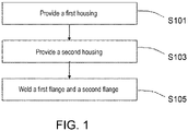
FIG. 1 is a schematic flowchart of a battery manufacturing method according to an exemplary embodiment. -
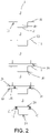
FIG. 2 is a schematic view of a structural flow of a battery manufacturing method according to an exemplary embodiment. -
FIG. 3 is a structural schematic view of a first reinforcing part of a battery manufacturing method according to a first exemplary embodiment. -
FIG. 4 is a structural schematic view of a first reinforcing part of a battery manufacturing method according to a second exemplary embodiment. -
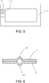
FIG. 5 is a structural schematic view of a first reinforcing part of a battery manufacturing method according to a third exemplary embodiment. -
FIG. 6 is a structural schematic view of cooperation between a first flange and a second flange of a battery manufacturing method according to an exemplary embodiment. -
FIG. 7 is a structural schematic view of cooperation between a first flange and a second flange of a battery manufacturing method according to another exemplary embodiment. -
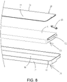
FIG. 8 is a partially exploded structural schematic view of a battery according to an exemplary embodiment. - The technical solutions in the exemplary embodiments of the disclosure will be described clearly and explicitly in conjunction with the drawings in the exemplary embodiments of the disclosure. The description proposed herein is just the exemplary embodiments for the purpose of illustrations only, not intended to limit the scope of the disclosure, so it should be understood that and various modifications and variations could be made thereto without departing from the scope of the disclosure.
- In the description of the present disclosure, unless otherwise specifically defined and limited, the terms "first", "second" and the like are only used for illustrative purposes and are not to be construed as expressing or implying a relative importance. The term "plurality" is two or more. The term "and/or" includes any and all combinations of one or more of the associated listed items.
- In particular, a reference to "the" object or "a" and "an" object is intended to denote also one of a possible plurality of such objects. Unless otherwise defined or described, the terms "connect", "fix" should be broadly interpreted, for example, the term "connect" can be "fixedly connect", "detachably connect", "integrally connect", "electrically connect" or "signal connect". The term "connect" also can be "directly connect" or "indirectly connect via a medium". For the persons skilled in the art, the specific meanings of the abovementioned terms in the present disclosure can be understood according to the specific situation.
- Further, in the description of the present disclosure, it should be understood that spatially relative terms, such as "above", "below" "inside", "outside" and the like, are described based on orientations illustrated in the figures, but are not intended to limit the exemplary embodiments of the present disclosure.
- In the context, it should also be understood that when an element or features is provided "outside" or "inside" of another element(s), it can be directly provided "outside" or "inside" of the other element, or be indirectly provided "outside" or "inside" of the another element(s) by an intermediate element.
- The disclosure provides a battery manufacturing method and a battery to improve a battery structure.
- An embodiment of the disclosure provides a battery manufacturing method. Please refer to
FIG. 1 . The battery manufacturing method includes the following. - In Step S101, a
first housing 10 is provided. Thefirst housing 10 includes a bottom wall and a side wall. The side wall extends upward from the bottom wall. The side wall encloses to form an opening. The side wall extends outward from the opening to form afirst flange 11. A first reinforcingpart 111 is formed on thefirst flange 11. - In Step S103, a
second housing 20 is provided. Thesecond housing 20 includes an intermediate part and asecond flange 21. The intermediate part covers the opening. Thesecond flange 21 is in contact with thefirst flange 11. - In Step S105, the
first flange 11 and thesecond flange 21 are welded. - In the battery manufacturing method according to an embodiment of the disclosure, the first reinforcing
part 111 is formed on thefirst flange 11 of thefirst housing 10, thereby avoiding the issue of deformation of thefirst housing 10 when welding thefirst flange 11 and thesecond flange 21, so as to improve a battery structure. - It should be noted that the
first housing 10 includes the bottom wall and the side wall. The side wall extends upward from the bottom wall. The side wall encloses to form an opening, that is, thefirst housing 10 forms anaccommodating cavity 40 and the opening is an opening of theaccommodating cavity 40. Thefirst flange 11 is formed in a circumferential direction of the opening of theaccommodating cavity 40. Thefirst flange 11 is a circumferentially closed structure. - The
second housing 20 includes the intermediate part and thesecond flange 21, that is, the intermediate part may be a plate structure. Thesecond flange 21 is disposed around a circumferential direction of the intermediate part. Thesecond flange 21 is a circumferentially closed structure. In some embodiments, it is not excluded that the intermediate part is formed with a recess, that is, similar to theaccommodating cavity 40. At this time, the depth of theaccommodating cavity 40 of thesecond housing 20 may be less than the depth of theaccommodating cavity 40 of thefirst housing 10. - In an embodiment, the
second housing 20 includes thesecond flange 21. A second reinforcingpart 211 is formed on thesecond flange 21, that is, the second reinforcingpart 211 may implement the function of reinforcing thesecond housing 20, thereby avoiding the issue of deformation of thefirst flange 11 and thesecond flange 21 when welding thefirst flange 11 and thesecond flange 21. - It should be noted that the
first flange 11 of thefirst housing 10 and thesecond flange 21 of thesecond housing 20 are oppositely disposed. Thefirst flange 11 and thesecond flange 21 do not form an accommodating space of a battery. - The
first flange 11 and thesecond flange 21 may be configured to connect thefirst housing 10 and thesecond housing 20, that is, the connection between thefirst housing 10 and thesecond housing 20 is implemented through welding thefirst flange 11 and thesecond flange 21. - Optionally, based on the welding of the
first flange 11 and thesecond flange 21, a firstmain body part 12 of thefirst housing 10 and a secondmain body part 22 of thesecond housing 20 may be welded. For example, one of the firstmain body part 12 and the secondmain body part 22 is a plate, which also facilitates the welding of the firstmain body part 12 and the secondmain body part 22. Thefirst flange 11 may be disposed around an outer circumferential edge of the firstmain body part 12, and thesecond flange 21 may be disposed around an outer circumferential edge of the secondmain body part 22, that is, thefirst flange 11 and thesecond flange 21 may be a circumferentially closed structure. The firstmain body part 12 includes the bottom wall and the side wall. The secondmain body part 22 includes the intermediate part. - It should be noted that the
first housing 10 and thesecond housing 20 are provided regardless of the sequence. - In an embodiment, the battery manufacturing method further includes: cutting at least part of the
first flange 11 after welding thefirst flange 11 and thesecond flange 21 to remove at least part of the first reinforcingpart 111. The first reinforcingpart 111 is configured to mainly serve the function of reinforcement when welding, so the first reinforcingpart 111 may be removed after completing the welding, thereby reducing the length of thefirst flange 11, so as to reduce a circumferential occupied area of the battery. - Correspondingly, when the
second housing 20 includes thesecond flange 21 and the second reinforcingpart 211 is formed on thesecond flange 21, at least part of thesecond flange 21 is cut to remove at least part of the second reinforcingpart 211. - It should be noted that the cutting of the
first flange 11 and thesecond flange 21 may be completed through one cutting process, that is, the cutting of the second flange 2 may be completed when cutting thefirst flange 11. A laser cutting process may be adopted to cut thefirst flange 11 and thesecond flange 21. Of course, in some embodiments, it is not excluded to respectively cut thefirst flange 11 and thesecond flange 21 through two processes. - Optionally, when implementing the welding of the
first housing 10 and thesecond housing 20 through thefirst flange 11 and thesecond flange 21, a part of thefirst flange 11 and thesecond flange 21 is cut, that is, a specific length of thefirst flange 11 and thesecond flange 21 is reserved. - Optionally, when implementing the welding of the
first housing 10 and thesecond housing 20 through the firstmain body part 12 and the secondmain body part 22, thefirst flange 11 and thesecond flange 21 may be completely cut. Alternatively, a part of thefirst flange 11 and thesecond flange 21 is cut, that is, a specific length of thefirst flange 11 and thesecond flange 21 is reserved. At this time, the reservedfirst flange 11 andsecond flange 21 may be used as a heat dissipation fin. Of course, the reservedfirst flange 11 andsecond flange 21 may also be used as a subsequent installation and positioning component, which is not limited here. - In an embodiment, the
first flange 11 and thesecond flange 21 are welded to form awelding seam 30. Thewelding seam 30 does not overlap with at least part of the first reinforcingpart 111, thereby ensuring the welding quality. Also, thewelding seam 30 will not be excessively cut off when subsequently cutting off the first reinforcingpart 111. Thewelding seam 30 is a circumferentially closed structure, thereby ensuring the reliability of the connection between thefirst housing 10 and thesecond housing 20 and ensuring that a relatively closed space may be formed between thefirst housing 10 and thesecond housing 20. - Correspondingly, when the
second housing 20 includes thesecond flange 21 and the second reinforcingpart 211 is formed on thesecond flange 21, thewelding seam 30 does not overlap with at least part of the second reinforcingpart 211. - In an embodiment, the
welding seam 30 and the first reinforcingpart 111 are spaced apart. Cutting is performed between thewelding seam 30 and the first reinforcingpart 111 to remove the first reinforcingpart 111. The first reinforcingpart 111 needs to be avoided when welding thefirst flange 11, so that the first reinforcingpart 111 may be completely cut off when subsequently cutting off a part of thefirst flange 11, and a part of thewelding seam 30 will not be cut off. - Correspondingly, when the
second housing 20 includes thesecond flange 21 and the second reinforcingpart 211 is formed on thesecond flange 21, the second reinforcingpart 211 needs to be avoided when welding thesecond flange 21, so that the second reinforcingpart 211 may be completely cut off when subsequently cutting off a part of thesecond flange 21, and a part of thewelding seam 30 will not be cut off. - In an embodiment, the
first flange 11 retains 0.1 mm to 5 mm after cutting, which not only ensures the reliability of welding, but also does not increase the area of the battery too much. - Correspondingly, when the
second housing 20 includes thesecond flange 21, thesecond flange 21 retains 0.1 mm to 5 mm after cutting, and outer circumferential edges of thefirst flange 11 and thesecond flange 21 may be completely aligned. That is, after welding and connecting thefirst housing 10 and thesecond housing 20 through thefirst flange 11 and thesecond flange 21, a part of thefirst flange 11 and thesecond flange 21 is cut off, so that a reserved length of thefirst flange 11 and thesecond flange 21 is basically 0.1 mm to 5 mm. The reserved length of thefirst flange 11 and thesecond flange 21 may be consistent or may be, of course, inconsistent. - It should be noted that for welding and connecting the
first housing 10 and thesecond housing 20 through thefirst flange 11 and thesecond flange 21, it is emphasized that thefirst housing 10 and thesecond housing 20 may be welded and connected mainly through thefirst flange 11 and thesecond flange 21. It is not excluded that the firstmain body part 12 and the secondmain body part 22 have a welding relationship at the same time. In an embodiment, at least one of thefirst housing 10 and thesecond housing 20 is formed with theaccommodating cavity 40 for accommodating components such as a cell. - The materials of the
first housing 10 and thesecond housing 20 may be stainless steel or aluminum, which has good corrosion resistance and sufficient strength. - The thickness of the
first housing 10 is consistent, which not only has strong structural stability, but also facilitates processing. The thickness of thesecond housing 20 is consistent. The thickness of thefirst housing 10 may be equal to the thickness of thesecond housing 20. - Optionally, the
first housing 10 and thesecond housing 20 may be both formed with theaccommodating cavities 40. After docking thefirst housing 10 and thesecond housing 20, the cell is located in a cavity formed by the twoaccommodating cavities 40. The depths of theaccommodating cavities 40 of thefirst housing 10 and thesecond housing 20 may be the same or different, which is not limited here. - Optionally, the
first housing 10 is a plate. Thesecond housing 20 is formed with theaccommodating cavity 40. The cell is located in theaccommodating cavity 40. The configuration of the plate may facilitate subsequent connection and is less difficult to process. - In an embodiment, the
accommodating cavity 40 is obtained through stamping aflat plate 1, that is, theaccommodating cavity 40 is stamped to be formed through selecting theflat plate 1 and a stamping process. During the specific process of stamping, a supporting platform with a groove may be selected, so that theaccommodating cavity 40 may be formed through stamping, that is, thefirst housing 10 or thesecond housing 20 is formed. A part of theflat plate 1 without stamping forms a flange. - Optionally, the
first housing 10 is formed with theaccommodating cavity 40. The first reinforcingpart 111 is formed before stamping theflat plate 1, that is, the first reinforcingpart 111 may be formed on theflat plate 1 first, and then thefirst housing 10 is stamped to be formed through a stamping process. At this time, a segment located on a plane where the opening of theaccommodating cavity 40 is at is thefirst flange 11 of thefirst housing 10. - Optionally, the
first housing 10 is formed with theaccommodating cavity 40. The first reinforcingpart 111 is formed after stamping theflat plate 1, that is, thefirst housing 10 may be stamped to be formed through theflat plate 1 first. At this time, a segment located on the plane where the opening of theaccommodating cavity 40 is at is thefirst flange 11 of thefirst housing 10. Then, the first reinforcingpart 111 is formed on thefirst flange 11. - Correspondingly, the
second housing 20 is formed with theaccommodating cavity 40. The second reinforcingpart 211 is formed before stamping theflat plate 1, that is, the second reinforcingpart 211 may be formed on theflat plate 1 first, and then thesecond housing 20 is stamped to be formed through a stamping process. At this time, a segment located on the plane where the opening of theaccommodating cavity 40 is at is thesecond flange 21 of thesecond housing 20. - Alternatively, the
second housing 20 is formed with theaccommodating cavity 40. The second reinforcingpart 211 is formed after stamping theflat plate 1, that is, thesecond housing 20 may be stamped to be formed through theflat plate 1 first. At this time, a segment located on the plane where the opening of theaccommodating cavity 40 is at is thesecond flange 21 of thesecond housing 20. Then, the second reinforcingpart 211 is formed on thesecond flange 21. - Optionally, the
accommodating cavity 40 and the first reinforcingpart 111 on thefirst housing 10 are obtained through synchronously stamping theflat plate 1, that is, theflat plate 1 may be simultaneously stamped through two different stamping heads, thereby forming thefirst housing 10 with the first reinforcingpart 111. At this time, the first reinforcingpart 111 is a first protrusion, that is, a groove is formed on thefirst housing 10. - Correspondingly, the
accommodating cavity 40 and the second reinforcingpart 211 on thesecond housing 20 are obtained through synchronously stamping theplate 1, that is, theplate 1 may be simultaneously stamped through two different stamping heads, thereby forming thesecond housing 20 with the second reinforcingpart 211. At this time, the second reinforcingpart 211 is a second protrusion. - In an embodiment, the
first housing 10 further includes the firstmain body part 12. Thefirst flange 11 is disposed around the outer circumferential edge of the firstmain body part 12. The first reinforcingpart 111 is disposed on thefirst flange 11 around the firstmain body part 12, that is, the first reinforcingpart 111 forms a circumferentially closed structure, thereby implementing the overall reinforcement of thefirst flange 11, as shown inFIG. 3 . The firstmain body part 12 includes the bottom wall and the side wall. The opening is an opening of the firstmain body part 12. The first reinforcingpart 111 is disposed on thefirst flange 11 around the firstmain body part 12, that is, the first reinforcingpart 111 is disposed on thefirst flange 11 around the opening. - Optionally, as shown in
FIG. 4 , the first reinforcingpart 111 is disposed in a length direction of thefirst flange 11, and an extension direction of the first reinforcingpart 111 is parallel to a width direction of thefirst flange 11, that is, the first reinforcingpart 111 is disposed on a segment with a longer length of thefirst flange 11, and the extension direction of the first reinforcingpart 111 is perpendicular to the length direction of thefirst flange 11 and is parallel to the width direction of thefirst flange 11. There may be at least two first reinforcingparts 111. The at least two first reinforcingparts 111 are spaced apart. - Optionally, as shown in
FIG. 5 , the first reinforcingpart 111 is disposed in the width direction of thefirst flange 11, and the extension direction of the first reinforcingpart 111 is parallel to the length direction of thefirst flange 11, that is, the first reinforcingpart 111 is disposed on a segment with a shorter length of thefirst flange 11, and the extension direction of the first reinforcingpart 111 is parallel to the length direction of thefirst flange 11 and is perpendicular to the width direction of thefirst flange 11. There may be at least two first reinforcingparts 111. The at least two first reinforcingparts 111 are spaced apart. - Optionally, the width direction of the
first flange 11 and the length direction of thefirst flange 11 may be both disposed with the first reinforcingparts 111, that is, the first reinforcingpart 111 is disposed in the length direction of thefirst flange 11, and the extension direction of the first reinforcingpart 111 is parallel to the width direction of thefirst flange 11; and the first reinforcingpart 111 is disposed in the width direction of thefirst flange 11, and the extension direction of the first reinforcingpart 111 is parallel to the length direction of thefirst flange 11. - Optionally, the first reinforcing
part 111 is disposed in the length direction of thefirst flange 11, and the extension direction of the first reinforcingpart 111 is parallel to the length direction of thefirst flange 11, so as to avoid deformation of thefirst flange 11. Further, thefirst flanges 11 in the two opposite length directions are both disposed with the first reinforcingparts 111. - Optionally, the first reinforcing
part 111 is disposed in the width direction of thefirst flange 11, and the extension direction of the first reinforcingpart 111 is parallel to the width direction of thefirst flange 11. Further, thefirst flanges 11 in the two opposite width directions are both disposed with the first reinforcingparts 111. - Correspondingly, the
second housing 20 further includes the secondmain body part 22. Thesecond flange 21 is disposed around the outer circumferential edge of the secondmain body part 22. For the configuration of the second reinforcingpart 211 on thesecond flange 21, reference may be made to the above embodiment, which will not be repeated here. - It should be noted that, regardless of whether the first reinforcing
part 111 is disposed in the width direction or the length direction of thefirst flange 11, the first reinforcingpart 111 will not span across thefirst flange 11, so that the first reinforcingpart 111 may be completely cut off when cutting off a part of thefirst flange 11. Of course, in some embodiments, it is not excluded that the first reinforcingpart 111 spans across thefirst flange 11, that is, a part of the first reinforcingpart 111 may be reserved when cutting off thefirst flange 11. The configuration of the second reinforcingpart 211 on thesecond flange 21 is also similar. - In an embodiment, as shown in
FIG. 2 , theflat plate 1 is provided. Thefirst housing 10 is formed through stamping. The first reinforcingpart 111 is formed on thefirst flange 11 of thefirst housing 10. Thesecond housing 20 is formed. Thesecond housing 20 may be a plate. The second reinforcingpart 211 is formed on thesecond housing 20, and thefirst housing 10 and thesecond housing 20 are welded to form thewelding seam 30. Finally, a part of thefirst flange 11 and thesecond flange 21 is cut off. - In an embodiment, the
flat plate 1 is provided. Thesecond housing 20 is formed through stamping. The second reinforcingpart 211 is formed on thesecond flange 21 of thesecond housing 20. Thefirst housing 10 is formed. Thefirst housing 10 may be a plate. The first reinforcingpart 111 is formed on thefirst housing 10, and thefirst housing 10 and thesecond housing 20 are welded to form thewelding seam 30. Finally, a part of thefirst flange 11 and thesecond flange 21 is cut off. - In an embodiment, the first reinforcing
part 111 is the first protrusion, and the first protrusion protrudes toward one side of thefirst flange 11 away from thesecond housing 20, so as to avoid contact between the first reinforcingpart 111 and thesecond housing 20 to ensure the subsequent stable welding of thefirst housing 10 and thesecond housing 20. - In an embodiment, the
second housing 20 includes thesecond flange 21. The second reinforcingpart 211 is formed on thesecond flange 21. The second reinforcingpart 211 is the second protrusion, and the second protrusion protrudes toward one side of thesecond housing 20 away from thefirst housing 10; and the first reinforcingpart 111 is the first protrusion, and the first protrusion protrudes toward one side of thefirst flange 11 away from thesecond housing 20, that is, the first protrusion and the second protrusion protrude away from each other, so that there will be no contact interference between the two and corresponding components, specifically as shown inFIG. 6 . - Optionally, as shown in
FIG. 7 , the second protrusion protrudes toward one side of thesecond housing 20 close to thefirst housing 10, and the first reinforcingpart 111 is the first protrusion, and the first protrusion protrudes toward one side of thefirst flange 11 away from thesecond housing 20, so that the second protrusion may be inserted into a groove formed by the first protrusion, that is, the first protrusion and the second protrusion may also implement the positioning of thefirst housing 10 and thesecond housing 20 on the basis of serving the function of reinforcement. The configuration of a special positioning structure is not necessary. - It should be noted that the first reinforcing
part 111 and the second reinforcingpart 211 may be reinforcing ribs. The reinforcing ribs may be structures additionally disposed on thefirst housing 10 and thesecond housing 20 or the reinforcing ribs may be protrusions formed through stamping thefirst housing 10 and thesecond housing 20, so the reinforcing ribs constitute the function of reinforcement. For example, the first protrusion protrudes toward one side of thefirst flange 11 away from thesecond housing 20 to form a groove. The groove may be configured to accommodate the second protrusion. The reinforcing ribs are disposed to prevent the overall housing from larger deformation, provide a specific amount of rigidity for the housing, and ensure the flatness of the housing to facilitate the subsequent welding of thefirst housing 10 and thesecond housing 20. - In an embodiment, welding the
first housing 10 and thesecond housing 20 includes: welding thefirst flange 11 and thesecond flange 21, that is, the fixed connection between thefirst housing 10 and thesecond housing 20 is implemented through thefirst flange 11 and thesecond flange 21. - In an embodiment, before welding the
first flange 11 and thesecond flange 21, acell 50 is placed between thefirst housing 10 and thesecond housing 20 to seal thecell 50 after welding thefirst flange 11 and thesecond flange 21, so that the fixing of the position of thecell 50 is also implemented. - In an embodiment, the
cell 50 is a laminated cell, which is not only convenient for grouping, but may also be processed to obtain a longer battery. Thecell 50 has a first pole piece, a second pole piece electrically opposite to the first pole piece, and a diaphragm piece disposed between the first pole piece and the second pole piece that are stacked on top of one another, so that multiple pairs of the first pole piece and the second pole piece are stacked to form the laminated cell. - Optionally, the battery may be a wound battery, that is, the first pole piece, the second pole piece electrically opposite to the first pole piece, and the diaphragm piece disposed between the first pole piece and the second pole piece are wound to obtain the wound battery.
- In an embodiment, as shown in
FIG. 8 , thecell 50 includes a cellmain body 51 and atab 52. Thetab 52 extends from a length direction of the cellmain body 51. - A
pole assembly 60 is installed on thefirst housing 10 or thesecond housing 20. Before welding thefirst housing 10 and thesecond housing 20, thetab 52 is connected with thepole assembly 60. Thetab 52 and thepole assembly 60 may be directly connected, that is, thetab 52 and thepole assembly 60 may be directly welded, or thetab 52 and thepole assembly 60 may be connected through a metal adapting piece. The specific connection may be welding, but manners such as the use of a riveted joint are not excluded and are not limited here. - It should be noted that the cell
main body 51 includes more than two pole pieces. Thetab 52 includes more than two single tabs. The single tabs respectively extend from the corresponding pole pieces. The width of the single tab is less than the width of the pole piece. Multiple single tabs are stacked to form thetab 52, which is connected with thepole assembly 60. Thetab 52 may be welded to thepole assembly 60. The single tab is made of metal foil with good electrical and thermal conductivity, such as aluminum, copper, or nickel. - In some embodiments, there are two
pole assemblies 60. The twopole assemblies 60 are respectively a positive pole assembly and a negative pole assembly. There are also twotabs 52. The twotabs 52 are respectively a positive tab and a negative tab. The positive pole assembly is connected with the positive tab. The negative pole assembly is connected with the negative tab. - It should be noted that any one of laser welding, ultrasonic welding, and resistance welding may be adopted for the welding.
- An embodiment of the disclosure also provides a battery, which includes the battery obtained by the battery manufacturing method.
- The battery according to an embodiment of the disclosure includes a
first housing 10 and asecond housing 20. A first reinforcingpart 111 is formed on afirst flange 11 of thefirst housing 10, thereby avoiding the issue of deformation of thefirst housing 10 when welding thefirst housing 10 and thesecond housing 20, so as to improve a battery structure. - Optionally, the battery has an approximate rectangular structure, that is, omitting processing and manufacturing errors, the battery may have a rectangular structure.
- In an embodiment, the length of the battery is a, where 400 mm ≤ a ≤ 2500 mm, the width of the battery is b, and the height of the battery is c, where 2b ≤ a ≤ 50b and/or 0.5c ≤ b ≤ 20c.
- Further, 50 mm ≤b ≤ 200 mm and 10 mm ≤ c ≤ 100 mm.
- Further, 4b ≤ a ≤ 25b and/or 2c ≤ b ≤ 10c.
- For the battery in the above embodiment, in the case where sufficient energy density is ensured, the ratio of the length to the width of the battery is larger. Further, the ratio of the width to the height of the battery is larger.
- In an embodiment, the length of the battery is a, the width of the battery is b, and the height of the battery is c, where 4b ≤ a ≤ 7b and/or 3c ≤ b ≤ 7c.
- In an embodiment, the length of the battery is a and the width of the battery is b, where 4b ≤ a ≤ 7b, that is, the ratio of the length to the width of the battery in the embodiment is larger, so as to increase the energy density of the battery and facilitate subsequently forming a battery module.
- In an embodiment, the height of the battery is c, where 3c ≤ b ≤ 7c, and the ratio of the width to the height of the battery is larger, which also facilitates formation in the case where sufficient energy density is ensured.
- Optionally, the length of the battery may be 500 mm to 1500 mm, the width of the battery may be 80 mm to 150 mm, and the height of the battery may be 15 mm to 25 mm.
- It should be noted that the length of the battery is the size of the battery in a length direction, the width of the battery is the size of the battery in a width direction, and the height of the battery is the size of the battery in a height direction, that is, the thickness of the battery. The battery has the length direction and the width direction, and the length direction and the width direction are both linear directions. The length direction may be a longer extension direction of the battery and the width direction may be a shorter extension direction of the battery. The height direction may be a thickness direction of the battery.
- Other embodiments of the disclosure will be apparent to those skilled in the art from consideration of the specification and practice of the disclosure disclosed herein. The disclosure is intended to cover any variations, uses or adaptations of the disclosure. These variations, uses, or adaptations follow the general principles of the disclosure and include common general knowledge or conventional technical means in the art that are not disclosed in the present disclosure.
Claims (12)
- A battery manufacturing method, comprising:providing a first housing (10), wherein the first housing (10) comprises a bottom wall and a side wall, the side wall extends upward from the bottom wall, the side wall encloses to form an opening, the side wall extends outward from the opening to form a first flange (11), and a first reinforcing part (111) is formed on the first flange (11);providing a second housing (20), wherein the second housing (20) comprises an intermediate part and a second flange (21), the intermediate part covers the opening, and the second flange (21) is in contact with the first flange (11); andwelding the first flange (11) and the second flange (21).
- The battery manufacturing method according to claim 1, further comprising:
cutting at least part of the first flange (11) after welding the first flange (11) and the second flange (21) to remove at least part of the first reinforcing part (111). - The battery manufacturing method according to claim 2, wherein the first flange (11) and the second flange (21) are welded to form a welding seam (30), and at least part of the first reinforcing part (111) does not overlap with the welding seam (30).
- The battery manufacturing method according to claim 3, wherein the welding seam (30) and the first reinforcing part (111) are spaced apart, and cutting is performed between the welding seam (30) and the first reinforcing part (111) to remove the first reinforcing part (111).
- The battery manufacturing method according to claim 2, wherein the first flange (11) retains 0.1 mm to 5 mm after cutting.
- The battery manufacturing method according to claim 1, wherein the first housing (10) is formed with an accommodating cavity (40), and the accommodating cavity (40) is obtained through stamping a flat plate (1); or
the accommodating cavity (40) and the first reinforcing part (111) are obtained through synchronously stamping a flat plate (1). - The battery manufacturing method according to claim 1, wherein the first reinforcing part (111) is disposed on the first flange (11) around the opening; the first reinforcing part (111) is disposed in a length direction of the first flange (11), and an extension direction of the first reinforcing part (111) is parallel to a width direction of the first flange (11); the first reinforcing part (111) is disposed in a width direction of the first flange (11), and an extension direction of the first reinforcing part (111) is parallel to a length direction of the first flange (11); the first reinforcing part (111) is disposed in a length direction of the first flange (11), and an extension direction of the first reinforcing part (111) is parallel to the length direction of the first flange (11); or the first reinforcing part (111) is disposed in a width direction of the first flange (11), and an extension direction of the first reinforcing part (111) is parallel to the width direction of the first flange (11).
- The battery manufacturing method according to any one of claims 1-7, wherein the first reinforcing part (111) is a first protrusion, and the first protrusion protrudes toward one side of the first flange (11) away from the second housing (20).
- The battery manufacturing method according to claim 8, wherein a second reinforcing part (211) is formed on the second flange (21); and
the second reinforcing part (211) is a second protrusion, and the second protrusion protrudes toward one side of the second housing (20) away from the first housing (10); or the first protrusion protrudes toward one side of the first flange (11) away from the second housing (20) to form a groove, and the second protrusion protrudes toward one side of the second housing (20) close to the first housing (10) to be inserted into the groove. - The battery manufacturing method according to claim 1, wherein before welding the first flange (11) and the second flange (21), a cell (50) is placed between the first housing (10) and the second housing (20) to seal the cell (50) after welding the first flange (11) and the second flange (21).
- A battery, comprising a battery obtained by the battery manufacturing method according to any one of claims 1-10.
- The battery according to claim 11, wherein a length of the battery is a, a width of the battery is b, and a height of the battery is c, where 2b ≤ a ≤ 50b and/or 0.5c ≤ b ≤ 20c; and
400 mm ≤ a ≤ 2500 mm.
Applications Claiming Priority (1)
| Application Number | Priority Date | Filing Date | Title |
|---|---|---|---|
| CN202110526792.6A CN115347286B (en) | 2021-05-14 | 2021-05-14 | Battery manufacturing method and battery |
Publications (1)
| Publication Number | Publication Date |
|---|---|
| EP4089803A1 true EP4089803A1 (en) | 2022-11-16 |
Family
ID=77126596
Family Applications (1)
| Application Number | Title | Priority Date | Filing Date |
|---|---|---|---|
| EP21188374.9A Pending EP4089803A1 (en) | 2021-05-14 | 2021-07-29 | Battery manufacturing method and battery |
Country Status (3)
| Country | Link |
|---|---|
| US (1) | US12126033B2 (en) |
| EP (1) | EP4089803A1 (en) |
| CN (1) | CN115347286B (en) |
Families Citing this family (2)
| Publication number | Priority date | Publication date | Assignee | Title |
|---|---|---|---|---|
| CN219497955U (en) * | 2022-12-13 | 2023-08-08 | 通快(中国)有限公司 | Battery and laser welding system |
| CN119627330A (en) * | 2023-09-13 | 2025-03-14 | 宁德时代新能源科技股份有限公司 | Battery cell, method for manufacturing battery cell, battery and power-using device |
Citations (4)
| Publication number | Priority date | Publication date | Assignee | Title |
|---|---|---|---|---|
| GB935337A (en) * | 1960-10-08 | 1963-08-28 | Bosch Gmbh Robert | Improvements relating to joining parts of thermoplastic synthetic resin by welding |
| US5411616A (en) * | 1993-12-20 | 1995-05-02 | Motorola, Inc. | Method for ultrasonically welding thin-walled components |
| EP3070779B1 (en) * | 2013-11-11 | 2019-08-28 | Nissan Motor Co., Ltd | Method for manufacturing film-packaged cell |
| CN111564576A (en) * | 2020-06-23 | 2020-08-21 | 瑞声科技(南京)有限公司 | Button cell |
Family Cites Families (8)
| Publication number | Priority date | Publication date | Assignee | Title |
|---|---|---|---|---|
| KR100319108B1 (en) * | 1999-04-16 | 2001-12-29 | 김순택 | Case of the secondary battery |
| KR100571269B1 (en) * | 2004-09-22 | 2006-04-13 | 삼성에스디아이 주식회사 | Pouches for secondary batteries and pouch type secondary batteries |
| US8771866B2 (en) * | 2010-03-30 | 2014-07-08 | Samsung Sdi Co., Ltd. | Pouch type secondary battery and the fabrication method thereof |
| CN201877526U (en) * | 2010-12-20 | 2011-06-22 | 东莞新能源科技有限公司 | Lithium ion battery |
| DE102012018038A1 (en) * | 2012-09-13 | 2014-03-13 | Daimler Ag | Single cell and battery of a plurality of single cells |
| CN207558835U (en) * | 2017-11-29 | 2018-06-29 | 长城汽车股份有限公司 | Battery pack housing and with its battery pack |
| CN210897345U (en) * | 2019-12-30 | 2020-06-30 | 蜂巢能源科技有限公司 | Battery pack lower shell and battery pack |
| CN115645760A (en) | 2022-11-09 | 2023-01-31 | 华中科技大学同济医学院附属协和医院 | Intracavitary radiotherapy device for gynecological tumor |
-
2021
- 2021-05-14 CN CN202110526792.6A patent/CN115347286B/en active Active
- 2021-07-22 US US17/383,356 patent/US12126033B2/en active Active
- 2021-07-29 EP EP21188374.9A patent/EP4089803A1/en active Pending
Patent Citations (4)
| Publication number | Priority date | Publication date | Assignee | Title |
|---|---|---|---|---|
| GB935337A (en) * | 1960-10-08 | 1963-08-28 | Bosch Gmbh Robert | Improvements relating to joining parts of thermoplastic synthetic resin by welding |
| US5411616A (en) * | 1993-12-20 | 1995-05-02 | Motorola, Inc. | Method for ultrasonically welding thin-walled components |
| EP3070779B1 (en) * | 2013-11-11 | 2019-08-28 | Nissan Motor Co., Ltd | Method for manufacturing film-packaged cell |
| CN111564576A (en) * | 2020-06-23 | 2020-08-21 | 瑞声科技(南京)有限公司 | Button cell |
Also Published As
| Publication number | Publication date |
|---|---|
| US12126033B2 (en) | 2024-10-22 |
| CN115347286A (en) | 2022-11-15 |
| US20220367950A1 (en) | 2022-11-17 |
| CN115347286B (en) | 2024-02-27 |
Similar Documents
| Publication | Publication Date | Title |
|---|---|---|
| CN212380440U (en) | Winding cells and batteries | |
| CN115621675B (en) | Terminal member and method for manufacturing terminal member | |
| KR102912445B1 (en) | Terminal component and secondary battery and assembled battery each including the terminal component | |
| US20220367949A1 (en) | Battery, battery apparatus, and battery manufacturing method | |
| US12126033B2 (en) | Battery manufacturing method and battery | |
| JP5613618B2 (en) | Cylindrical secondary battery | |
| JP2000090889A (en) | Thin battery | |
| US12489179B2 (en) | Terminal component, secondary battery, and battery pack | |
| CN111799429A (en) | Soft pack battery and soft pack battery assembly method | |
| JP6416696B2 (en) | Method for welding case body and lid and battery manufacturing method using the method | |
| EP4089802A1 (en) | Battery manufacturing method and battery | |
| CN219575873U (en) | Battery assembly | |
| US20230019424A1 (en) | Horn, terminal component, and secondary battery | |
| EP4012833A1 (en) | Sealed battery and method of manufacturing sealed battery | |
| JP2002246009A (en) | Alkaline storage battery | |
| JP2004214011A (en) | battery | |
| US12609420B2 (en) | Terminal component, secondary battery, and method for producing the terminal component | |
| US12057603B2 (en) | Terminal component, secondary battery, and method for manufacturing terminal component | |
| CN222546500U (en) | Battery Cell | |
| CN220439740U (en) | Batteries and battery devices | |
| JP2025167946A (en) | Secondary battery manufacturing method and secondary battery | |
| JP2023062844A (en) | Terminal component, secondary battery, and method of manufacturing terminal component |
Legal Events
| Date | Code | Title | Description |
|---|---|---|---|
| PUAI | Public reference made under article 153(3) epc to a published international application that has entered the european phase |
Free format text: ORIGINAL CODE: 0009012 |
|
| STAA | Information on the status of an ep patent application or granted ep patent |
Free format text: STATUS: REQUEST FOR EXAMINATION WAS MADE |
|
| 17P | Request for examination filed |
Effective date: 20210729 |
|
| AK | Designated contracting states |
Kind code of ref document: A1 Designated state(s): AL AT BE BG CH CY CZ DE DK EE ES FI FR GB GR HR HU IE IS IT LI LT LU LV MC MK MT NL NO PL PT RO RS SE SI SK SM TR |
|
| STAA | Information on the status of an ep patent application or granted ep patent |
Free format text: STATUS: EXAMINATION IS IN PROGRESS |
|
| 17Q | First examination report despatched |
Effective date: 20250203 |