EP4089795A1 - Battery box and battery pack, vehicle - Google Patents
Battery box and battery pack, vehicle Download PDFInfo
- Publication number
- EP4089795A1 EP4089795A1 EP21188363.2A EP21188363A EP4089795A1 EP 4089795 A1 EP4089795 A1 EP 4089795A1 EP 21188363 A EP21188363 A EP 21188363A EP 4089795 A1 EP4089795 A1 EP 4089795A1
- Authority
- EP
- European Patent Office
- Prior art keywords
- connecting portion
- buffer
- box cover
- battery
- box
- Prior art date
- Legal status (The legal status is an assumption and is not a legal conclusion. Google has not performed a legal analysis and makes no representation as to the accuracy of the status listed.)
- Pending
Links
Images
Classifications
-
- B—PERFORMING OPERATIONS; TRANSPORTING
- B60—VEHICLES IN GENERAL
- B60K—ARRANGEMENT OR MOUNTING OF PROPULSION UNITS OR OF TRANSMISSIONS IN VEHICLES; ARRANGEMENT OR MOUNTING OF PLURAL DIVERSE PRIME-MOVERS IN VEHICLES; AUXILIARY DRIVES FOR VEHICLES; INSTRUMENTATION OR DASHBOARDS FOR VEHICLES; ARRANGEMENTS IN CONNECTION WITH COOLING, AIR INTAKE, GAS EXHAUST OR FUEL SUPPLY OF PROPULSION UNITS IN VEHICLES
- B60K1/00—Arrangement or mounting of electrical propulsion units
- B60K1/04—Arrangement or mounting of electrical propulsion units of the electric storage means for propulsion
-
- B—PERFORMING OPERATIONS; TRANSPORTING
- B60—VEHICLES IN GENERAL
- B60L—PROPULSION OF ELECTRICALLY-PROPELLED VEHICLES; SUPPLYING ELECTRIC POWER FOR AUXILIARY EQUIPMENT OF ELECTRICALLY-PROPELLED VEHICLES; ELECTRODYNAMIC BRAKE SYSTEMS FOR VEHICLES IN GENERAL; MAGNETIC SUSPENSION OR LEVITATION FOR VEHICLES; MONITORING OPERATING VARIABLES OF ELECTRICALLY-PROPELLED VEHICLES; ELECTRIC SAFETY DEVICES FOR ELECTRICALLY-PROPELLED VEHICLES
- B60L50/00—Electric propulsion with power supplied within the vehicle
- B60L50/50—Electric propulsion with power supplied within the vehicle using propulsion power supplied by batteries or fuel cells
- B60L50/60—Electric propulsion with power supplied within the vehicle using propulsion power supplied by batteries or fuel cells using power supplied by batteries
- B60L50/64—Constructional details of batteries specially adapted for electric vehicles
-
- H—ELECTRICITY
- H01—ELECTRIC ELEMENTS
- H01M—PROCESSES OR MEANS, e.g. BATTERIES, FOR THE DIRECT CONVERSION OF CHEMICAL ENERGY INTO ELECTRICAL ENERGY
- H01M10/00—Secondary cells; Manufacture thereof
- H01M10/60—Heating or cooling; Temperature control
- H01M10/61—Types of temperature control
- H01M10/613—Cooling or keeping cold
-
- H—ELECTRICITY
- H01—ELECTRIC ELEMENTS
- H01M—PROCESSES OR MEANS, e.g. BATTERIES, FOR THE DIRECT CONVERSION OF CHEMICAL ENERGY INTO ELECTRICAL ENERGY
- H01M10/00—Secondary cells; Manufacture thereof
- H01M10/60—Heating or cooling; Temperature control
- H01M10/62—Heating or cooling; Temperature control specially adapted for specific applications
- H01M10/625—Vehicles
-
- H—ELECTRICITY
- H01—ELECTRIC ELEMENTS
- H01M—PROCESSES OR MEANS, e.g. BATTERIES, FOR THE DIRECT CONVERSION OF CHEMICAL ENERGY INTO ELECTRICAL ENERGY
- H01M10/00—Secondary cells; Manufacture thereof
- H01M10/60—Heating or cooling; Temperature control
- H01M10/65—Means for temperature control structurally associated with the cells
- H01M10/655—Solid structures for heat exchange or heat conduction
- H01M10/6554—Rods or plates
-
- H—ELECTRICITY
- H01—ELECTRIC ELEMENTS
- H01M—PROCESSES OR MEANS, e.g. BATTERIES, FOR THE DIRECT CONVERSION OF CHEMICAL ENERGY INTO ELECTRICAL ENERGY
- H01M50/00—Constructional details or processes of manufacture of the non-active parts of electrochemical cells other than fuel cells, e.g. hybrid cells
- H01M50/20—Mountings; Secondary casings or frames; Racks, modules or packs; Suspension devices; Shock absorbers; Transport or carrying devices; Holders
- H01M50/204—Racks, modules or packs for multiple batteries or multiple cells
- H01M50/207—Racks, modules or packs for multiple batteries or multiple cells characterised by their shape
- H01M50/209—Racks, modules or packs for multiple batteries or multiple cells characterised by their shape adapted for prismatic or rectangular cells
-
- H—ELECTRICITY
- H01—ELECTRIC ELEMENTS
- H01M—PROCESSES OR MEANS, e.g. BATTERIES, FOR THE DIRECT CONVERSION OF CHEMICAL ENERGY INTO ELECTRICAL ENERGY
- H01M50/00—Constructional details or processes of manufacture of the non-active parts of electrochemical cells other than fuel cells, e.g. hybrid cells
- H01M50/20—Mountings; Secondary casings or frames; Racks, modules or packs; Suspension devices; Shock absorbers; Transport or carrying devices; Holders
- H01M50/233—Mountings; Secondary casings or frames; Racks, modules or packs; Suspension devices; Shock absorbers; Transport or carrying devices; Holders characterised by physical properties of casings or racks, e.g. dimensions
- H01M50/242—Mountings; Secondary casings or frames; Racks, modules or packs; Suspension devices; Shock absorbers; Transport or carrying devices; Holders characterised by physical properties of casings or racks, e.g. dimensions adapted for protecting batteries against vibrations, collision impact or swelling
-
- H—ELECTRICITY
- H01—ELECTRIC ELEMENTS
- H01M—PROCESSES OR MEANS, e.g. BATTERIES, FOR THE DIRECT CONVERSION OF CHEMICAL ENERGY INTO ELECTRICAL ENERGY
- H01M50/00—Constructional details or processes of manufacture of the non-active parts of electrochemical cells other than fuel cells, e.g. hybrid cells
- H01M50/20—Mountings; Secondary casings or frames; Racks, modules or packs; Suspension devices; Shock absorbers; Transport or carrying devices; Holders
- H01M50/249—Mountings; Secondary casings or frames; Racks, modules or packs; Suspension devices; Shock absorbers; Transport or carrying devices; Holders specially adapted for aircraft or vehicles, e.g. cars or trains
-
- H—ELECTRICITY
- H01—ELECTRIC ELEMENTS
- H01M—PROCESSES OR MEANS, e.g. BATTERIES, FOR THE DIRECT CONVERSION OF CHEMICAL ENERGY INTO ELECTRICAL ENERGY
- H01M50/00—Constructional details or processes of manufacture of the non-active parts of electrochemical cells other than fuel cells, e.g. hybrid cells
- H01M50/20—Mountings; Secondary casings or frames; Racks, modules or packs; Suspension devices; Shock absorbers; Transport or carrying devices; Holders
- H01M50/271—Lids or covers for the racks or secondary casings
-
- H—ELECTRICITY
- H01—ELECTRIC ELEMENTS
- H01M—PROCESSES OR MEANS, e.g. BATTERIES, FOR THE DIRECT CONVERSION OF CHEMICAL ENERGY INTO ELECTRICAL ENERGY
- H01M50/00—Constructional details or processes of manufacture of the non-active parts of electrochemical cells other than fuel cells, e.g. hybrid cells
- H01M50/20—Mountings; Secondary casings or frames; Racks, modules or packs; Suspension devices; Shock absorbers; Transport or carrying devices; Holders
- H01M50/289—Mountings; Secondary casings or frames; Racks, modules or packs; Suspension devices; Shock absorbers; Transport or carrying devices; Holders characterised by spacing elements or positioning means within frames, racks or packs
- H01M50/291—Mountings; Secondary casings or frames; Racks, modules or packs; Suspension devices; Shock absorbers; Transport or carrying devices; Holders characterised by spacing elements or positioning means within frames, racks or packs characterised by their shape
-
- H—ELECTRICITY
- H01—ELECTRIC ELEMENTS
- H01M—PROCESSES OR MEANS, e.g. BATTERIES, FOR THE DIRECT CONVERSION OF CHEMICAL ENERGY INTO ELECTRICAL ENERGY
- H01M2220/00—Batteries for particular applications
- H01M2220/20—Batteries in motive systems, e.g. vehicle, ship, plane
-
- Y—GENERAL TAGGING OF NEW TECHNOLOGICAL DEVELOPMENTS; GENERAL TAGGING OF CROSS-SECTIONAL TECHNOLOGIES SPANNING OVER SEVERAL SECTIONS OF THE IPC; TECHNICAL SUBJECTS COVERED BY FORMER USPC CROSS-REFERENCE ART COLLECTIONS [XRACs] AND DIGESTS
- Y02—TECHNOLOGIES OR APPLICATIONS FOR MITIGATION OR ADAPTATION AGAINST CLIMATE CHANGE
- Y02E—REDUCTION OF GREENHOUSE GAS [GHG] EMISSIONS, RELATED TO ENERGY GENERATION, TRANSMISSION OR DISTRIBUTION
- Y02E60/00—Enabling technologies; Technologies with a potential or indirect contribution to GHG emissions mitigation
- Y02E60/10—Energy storage using batteries
Definitions
- the disclosure relates to the technical field of batteries, and in particular, to a battery box, a battery pack, and a vehicle.
- the battery is one of the important elements in the electric vehicle.
- the battery is usually disposed in a battery box, and the battery box is mounted in the corresponding position of the electric vehicle.
- the battery box includes a box body and a box cover, etc., and the box cover may be connected to the box body.
- the vibration of the vehicle readily causes the box cover to vibrate.
- the vibration of the box cover affects the structure in the battery box, such as batteries, circuits, etc., and thus causes safety issues.
- the battery box includes:
- the buffer member is disposed between the beam and the box cover, and the buffer member is connected to the beam.
- the battery pack includes:
- the battery pack provided by an embodiment of the disclosure includes the battery box.
- the buffer member is disposed between the beam and the box cover, and the buffer member is connected to the beam.
- a vehicle includes the above battery pack.
- the vehicle provided by an embodiment of the disclosure includes the battery box.
- the buffer member is disposed between the beam and the box cover, and the buffer member is connected to the beam.
- connection In particular, a reference to “the” object or “a” and “an” object is intended to denote also one of a possible plurality of such objects.
- the terms “connect”, “fix” should be broadly interpreted, for example, the term “connect” can be “fixedly connect”, “detachably connect”, “integrally connect”, “electrically connect” or “signal connect”.
- the term “connect” also can be “directly connect” or “indirectly connect via a medium”.
- An object of the disclosure is to provide a battery box, a battery pack, and a vehicle, so as to reduce the vibration of the box cover in the battery box at least to a certain extent.
- the battery box includes a beam 110, a box cover 120, and buffer members 130.
- the buffer members 130 are disposed between the beam 110 and the box cover 120 and are connected to the beam 110.
- the box cover 120 is disposed at a side of the beam 110 away from the bottom plate, and the buffer members 130 are connected to the beam 110.
- the buffer members 130 between the beam 110 and the box cover 120 may buffer the vibration of the box cover 120 to improve safety, and solve the issue that excessive vibration of the box cover 120 damages the box cover 120 to improve the service life of the box cover 120. Potential damage to the batteries from the box cover 120 during vibration is also avoided, thus improving the service life of the batteries.
- the beam 110 may be disposed at a bottom plate 170, and the bottom plate 170 may be a flat plate structure or a flat plate-like structure.
- the bottom plate 170 may be a stainless-steel plate, an aluminum alloy plate, etc.
- An accommodating area is disposed on the bottom plate 170, and the accommodating area is configured to place batteries or battery assemblies.
- the orthographic projection of the batteries or the battery assemblies on the bottom plate is located in the accommodating area, and the batteries or the battery assemblies may be directly placed in the accommodating area, or other devices may also be disposed between the batteries or the battery assemblies and the bottom plate, such as a cooling device, etc., and the embodiments of the disclosure are not specifically limited in this regard.
- the bottom plate 170 may be provided with a frame 140 and the beam 110 thereon.
- the frame 140 includes a plurality of frame beams.
- the frame beams are configured to form an accommodating portion for placing batteries 100.
- the beam 110 is disposed at the accommodating portion.
- the beam 110 divides the accommodating portion into a plurality of battery compartments, each of the battery compartments is provided with a battery pack therein, and the battery pack has a plurality of batteries 100.
- the frame 140 and/or the beam 110 are connected to the batteries 100 to withstand at least a portion of the weight of the batteries 100.
- the batteries 100 are directly placed in the battery compartments, and there is no need to package a plurality of batteries into battery modules and mount them in the battery compartments.
- the batteries may be directly in contact with the bottom plate, the frame 140, and the beam 110.
- the batteries are connected to the frame 140 and the beam 110 by a connecting method such as a connecting adhesive.
- the beam 110 and the frame 140 withstand at least a portion of the weight of the batteries.
- the batteries are placed directly in the battery compartments, thereby increasing the number of batteries in the battery compartments, and thereby increasing the energy density of the battery pack. Since the batteries are directly mounted at the battery compartments, the box cover 120 may indirectly be in contact with the batteries during the vibration process, thus causing the batteries to be damaged.
- the box cover 120 and the beam 110 are connected by the buffer members 130, thus preventing the box cover 120 from damaging the batteries during vibration, and at the same time preventing the box cover 120 from being damaged. Further, the vibration of the box cover 120 may drive the box to vibrate, thus facilitating the mixing of electrolytes in the batteries, and thereby facilitating the reaction of the batteries.
- the accommodating area on the bottom plate may be a rectangular structure
- the frame 140 may include four frame beams, and the four frame beams are connected end to end to form a frame.
- the battery pack may include a first frame beam, a second frame beam, a third frame beam, and a fourth frame beam. The first frame beam, the second frame beam, the third frame beam, and the fourth frame beam are connected end to end and form a frame by welding.
- the beam 110 may be disposed in the frame.
- the beam 110 may include a first beam (a cross beam) and a second beam (vertical beam), and the first beam and the second beam are intersected.
- the first beam and the second beam are vertically disposed.
- the battery box may include one first beam and one second beam, the first beam and the first frame beam are parallel, and the second beam and the second frame beam are parallel.
- the first beam and the second beam divide the accommodating area into four battery compartments, and the batteries or the battery assemblies are respectively provided in the four battery compartments.
- the number of the first beam and the second beam may also be a plurality, and the embodiments of the disclosure are not limited thereto.
- the beam 110 and the bottom plate may be connected by welding, and the frame beams and the bottom plate may be connected by welding.
- the bottom surface of the beam 110 is in contact with the top surface of the bottom plate, the bottom surface of the beam 110 is a flat surface, and the top surface of the bottom plate is a flat surface. Therefore, fillet welding may be performed at two sides of the beam 110 to connect the beam 110 and the bottom plate.
- the bottom surface of the frame beams is in contact with the top surface of the bottom plate, the bottom surface of the frame beams is a flat surface, and the top surface of the bottom plate is a flat surface. Therefore, fillet welding may be performed at the outside and inside of the frame beams to connect the frame beams and the bottom plate.
- an adhesive containing groove may be disposed on the bottom plate and/or the beam 110, and a connecting adhesive layer may be disposed in the adhesive containing groove to connect the bottom plate and the beam 110.
- the adhesive containing groove may be disposed at the beam 110, or the adhesive containing groove may be disposed at the bottom plate, or the adhesive containing groove may be disposed on both the bottom plate and the beam 110.
- An adhesive injection channel may be disposed on the beam 110 or the bottom plate. The adhesive injection channel is configured to communicate with the outside after the beam 110 and the bottom plate are connected. The adhesive injection channel is connected to the adhesive containing groove.
- the connecting adhesive layer is disposed in the adhesive containing groove to glue the bottom plate to the beam 110.
- the buffer members 130 are disposed on the beam 110, and the buffer members 130 are located at a side of the inner beam 110 away from the bottom plate.
- both the beam 110 and the frame beams may be provided with the buffer members 130, which is not specifically limited in the embodiments of the disclosure.
- a first beam and a second beam are disposed in the frame 140 formed by the frame beams, and the first beam and the second beam are vertically disposed.
- a plurality of buffer members 130 are disposed on the first beam, and the plurality of buffer members 130 may be evenly distributed on the first beam.
- a plurality of buffer members 130 are disposed on the second beam, and the plurality of buffer members 130 are evenly distributed at the second beam.
- the buffer members 130 may be connected to the beam 110. At this time, the end of the buffer members 130 away from the beam 110 may provide buffer to the box cover 120 when the box cover 120 approaches the beam 110. Or two ends of the buffer members 130 may be connected to the beam 110 and the box cover 120 respectively.
- the first end of the buffer members 130 is connected to a side of the beam 110 close to the box cover 120 to facilitate the connection of the buffer members 130 and the beam 110 and avoid affecting other structures in the battery box.
- the second end of the buffer members 130 is connected to a side of the box cover 120 close to the beam 110.
- the buffer members 130 are connected to the beam 110 and the box cover 120 at the same time, and the buffer effect is better, and the buffer members 130 are connected to a side of the box cover 120 close to the beam 110 to facilitate the connection of the buffer members 130 and the box cover 120.
- the buffer members 130 and the beam 110 may be connected by one or a plurality of connecting methods of bolting, riveting, welding, and gluing.
- the buffer members 130 and the beam 110 may be connected by a combination of bolting and gluing; or the buffer members 130 and the beam 110 may be connected by a combination of riveting and gluing; or the buffer members 130 and the beam 110 may be connected by a combination of welding and gluing.
- an adhesive containing groove may be disposed on a surface of the buffer members 130 close to the beam 110, wherein the adhesive containing groove is filled with a connecting adhesive, and the buffer members 130 and the beam 110 are bonded by the connecting adhesive.
- a bolt hole needs to be disposed on the buffer members 130, and at this time, the adhesive containing groove and the bolt hole are not intersected. That is, the extension path of the adhesive container groove needs to avoid the bolt hole.
- a welding area may be disposed on the edge of the buffer members 130, and the adhesive containing groove is disposed between the welding areas at two sides of the buffer members 130.
- One or a plurality of connecting areas may be disposed on a side of the box cover 120 close to the bottom plate, and the connecting areas are configured to be connected to the buffer members 130.
- the buffer members 130 and the box cover 120 may be connected by one or a plurality of connecting methods of bolting, riveting, welding, and gluing.
- the buffer members 130 and the box cover 120 may be connected by a combination of bolting and gluing; or the buffer members 130 and the box cover 120 may be connected by a combination of riveting and gluing; or the buffer members 130 and the box cover 120 may be connected by a combination of welding and gluing.
- an adhesive containing groove may be disposed on a surface of the buffer members 130 close to the box cover 120, wherein the adhesive containing groove is filled with a connecting adhesive, and the buffer members 130 and the box cover 120 are bonded by the connecting adhesive.
- a bolt hole needs to be disposed on the buffer members 130, and at this time, the adhesive containing groove and the bolt hole are not intersected. That is, the extension path of the adhesive container groove needs to avoid the bolt hole.
- a welding area may be disposed on the edge of the buffer members 130, and the adhesive containing groove is disposed between the welding areas at two sides of the buffer members 130.
- the buffer members 130 include: a first connecting portion 131, a second connecting portion 132, and a buffer portion 133.
- the first connecting portion 131 is configured to be connected to the beam 110; the second connecting portion 132 is configured to be connected to the box cover 120; an end of the buffer portion 133 is connected to the first connecting portion 131, and another end of the buffer portion 133 is connected to the second connecting portion 132.
- a surface of the first connecting portion 131 close to the beam 110 may be a flat surface, and the flat surface is in contact with the top surface of the beam 110.
- the first connecting portion 131 and the beam 110 may be connected by a connecting method such as welding, bolting, riveting, or gluing.
- a surface of the second connecting portion 132 close to the box cover 120 may be a flat surface, and the flat surface is in contact with the top surface of the beam 110.
- the first connecting portion 131 and the beam 110 may be connected by a connecting method such as welding, bolting, riveting, or gluing.
- the buffer portion 133 is configured to provide a buffer when the box cover 120 is vibrated, so as to avoid excessive vibration of the box cover 120.
- the buffer portion 133 may have elasticity. When the force applied to the buffer members 130 by the box cover 120 is greater than a preset threshold, the buffer portion 133 may be elastically deformed, so as to buffer the vibration of the box cover 120.
- the first connecting portion 131, the second connecting portion 132, and the buffer portion 133 in the buffer members 130 may be an integrated structure.
- the first connecting portion 131, the second connecting portion 132, and the buffer portion 133 in the buffer members 130 may be integrally formed by casting or machining.
- the first connecting portion 131, the second connecting portion 132, and the buffer portion 133 in the buffer members 130 may be separate structures.
- the buffer portion 133 and the first connecting portion 131 and the second connecting portion 132 may be connected by welding, respectively, or the buffer portion 133 and the first connecting portion 131 and the second connecting portion 132 may be connected by riveting, respectively, or the buffer portion 133 and the first connecting portion 131 and the second connecting portion 132 may be connected by a bolt, respectively.
- the buffer portion 133 and the first connecting portion 131 and the second connecting portion 132 may also be connected in other ways, and the embodiments of the disclosure are not limited thereto.
- the materials of the first connecting portion 131, the second connecting portion 132, and the buffer portion 133 may be the same.
- the materials of the first connecting portion 131, the second connecting portion 132, and the buffer portion 133 may be stainless steel, aluminum alloy, etc.
- the thickness of the first connecting portion 131, the second connecting portion 132, and the buffer portion 133 are a flat plate structure, the thickness of the first connecting portion 131 is greater than the thickness of the buffer portion 133, and the thickness of the second connecting portion 132 is greater than the thickness of the buffer portion 133.
- the large thickness of the first connecting portion 131 and the second connecting portion 132 may ensure the connection strength of the buffer members 130 and the beam 110 and the buffer portion 133 and the box cover 120.
- the small thickness of the buffer portion 133 may ensure that the stiffness of the buffer portion 133 is within the preset required range, so that the buffer portion 133 may be elastically deformed when the box is vibrated.
- the materials of the first connecting portion 131, the second connecting portion 132, and the buffer portion 133 are different, and the stiffness of the first connecting portion 131 and the second connecting portion 132 is greater than the stiffness of the buffer portion 133.
- the large stiffness of the first connecting portion 131 and the second connecting portion 132 may ensure the stability of the connection of the beam 110 and the buffer members 130 and the buffer members 130 and the box cover 120, and the small stiffness of the buffer portion 133 may ensure that the stiffness of the buffer portion 133 is within the preset required range, so that the buffer portion 133 may be elastically deformed when the box is vibrated.
- the thicknesses of the first connecting portion 131, the second connecting portion 132, and the buffer portion 133 may be the same.
- the first connecting portion 131, the second connecting portion 132, and the buffer portion 133 have the same thickness to facilitate manufacture.
- the buffer members 130 may be, but not limited to, an I-shape, a Z-shape, an L-shape, and the like.
- the extending direction of the first connecting portion 131 is perpendicular to the extending direction of the buffer portion 133, the extending direction of the second connecting portion 132 is consistent with the extending direction of the first connecting portion 131, the structure is simple, and the buffering effect is good.
- the buffer members formed by the first connecting portion 131, the second connecting portion 132, and the buffer portion 133 are C-shaped.
- the buffer members 130 are C-shaped members having a simple structure, are easy to manufacture, and have a good buffer effect.
- the extending direction of the first connecting portion 131 and the extending direction of the buffer portion 133 are disposed perpendicularly. That is, the extending direction of the first connecting portion 131 and the extending direction of the buffer portion 133 are disposed perpendicularly within the tolerance range allowed by the process.
- the included angle between the extending direction of the first connecting portion 131 and the extending direction of the buffer portion 133 is a right angle, or the acute angle between the extending direction of the first connecting portion 131 and the extending direction of the buffer portion 133 is greater than a predetermined angle threshold.
- the acute angle between the extending direction of the first connecting portion 131 and the extending direction of the buffer portion 133 is greater than 89 degrees, 88 degrees, 87 degrees, etc.
- the extending direction of the second connecting portion 132 is consistent with the extending direction of the first connecting portion 131, meaning that the first connecting portion 131 and the second connecting portion 132 are located at a side of the buffer portion 133, and the first connecting portion 131 and the second connecting portion 132 are disposed in parallel.
- the parallel arrangement of the first connecting portion 131 and the second connecting portion 132 means that the extending direction of the first connecting portion 131 and the extending direction of the second connecting portion 132 are parallel within the tolerance range of the process.
- the acute angle between the extending direction of the first connecting portion 131 and the extending direction of the second connecting portion 132 is smaller than a preset threshold.
- the acute angle between the extending direction of the first connecting portion 131 and the extending direction of the second connecting portion 132 is less than 3 degrees, 2 degrees, 1 degree, etc.
- the buffer members 130 may be directly connected to the box cover 120 or the buffer members 130 may be indirectly connected to the box cover 120.
- the buffer members 130 and the box cover 120 may be directly connected by one or a plurality of connecting methods of bolting, riveting, welding, and gluing.
- a cold plate may be disposed at a side of the box cover 120 close to the bottom plate, the cold plate is connected to the box cover 120, and the buffer members 130 are connected to the cold plate.
- the cold plate and the box cover 120 may be connected by one or a plurality of methods of welding, bolting, riveting, and gluing.
- the buffer members 130 and the cold plate may be connected by one or a plurality of connecting methods of welding, bolting, riveting, and gluing.
- a mounting area is disposed on the box cover 120, and the cold plate is mounted at the mounting area.
- the mounting area may be a pit on the box cover 120, and the cold plate is disposed inside the pit.
- the second connecting portion 132 is connected to the cold plate, and the second connecting portion 132 and the cold plate may be connected by one or a plurality of methods of welding, bolting, riveting, and gluing.
- the box cover 120 may be integrated with a cold plate.
- a cooling liquid channel is disposed at a side of the box cover 120 close to the beam 110, and the batteries are cooled by a cooling liquid in the cooling liquid channel.
- the cooling liquid channel may also be disposed inside the box cover, which is not specifically limited in the embodiments of the disclosure.
- the buffer members 130 further include a first reinforcement portion 135 and a second reinforcement portion 136, and the first reinforcement portion 135 is connected to the first connecting portion 131 and the buffer portion 133, respectively; and the second reinforcement portion 136 is connected to the second connecting portion 132 and the buffer portion 133, respectively.
- the first reinforcement portion 135 is configured to improve the connection strength of the first connecting portion 131 and the buffer portion 133
- the second reinforcement portion 136 is configured to improve the connection strength of the first connecting portion 131 and the buffer portion 133.
- first reinforcement portion 135 may be a first reinforcement rib, and the first reinforcement rib is disposed at a portion where the first connecting portion 131 and the buffer portion 133 are connected.
- the second reinforcement portion 136 may be a second reinforcement rib, and the second reinforcement rib is disposed at a portion where the second connecting portion 132 and the buffer portion 133 are connected.
- the buffer members 130 include: the first connecting portion 131, the second connecting portion 132, the third connecting portion 134, and the buffer portion 133.
- the first connecting portion 131 is configured to be connected to the beam 110; the second connecting portion 132 is configured to be connected to the box cover 120; an end of the buffer portion 133 is connected to the first connecting portion 131, and another end of the buffer portion 133 is connected to the second connecting portion 132.
- the third connecting portion 134 and the buffer portion 133 are connected, and the third connecting portion 134 is located between the first connecting portion 131 and the second connecting portion 132.
- the battery box further includes a cooling member 180 (for example, a cold plate), the cooling member 180 is disposed between the beam 110 and the box cover 120, and the cooling member 180 is connected to the third connecting portion 134.
- the cooling member 180 is restricted by the third connecting portion 134 to avoid vibration of the cooling member 180.
- the battery box may also include a connecting wire harness, a conductive bar, a connector, etc., and the connecting wire harness, the conductive bar, or the connector may be connected to the third connecting portion 134, and the embodiments of the disclosure are not limited thereto.
- a surface of the first connecting portion 131 close to the beam 110 may be a flat surface, and the flat surface is in contact with the top surface of the beam 110.
- the first connecting portion 131 and the beam 110 may be connected by a connecting method such as welding, bolting, riveting, or gluing.
- a surface of the second connecting portion 132 close to the box cover 120 may be a flat surface, and the flat surface is in contact with the top surface of the beam 110.
- the first connecting portion 131 and the beam 110 may be connected by a connecting method such as welding, bolting, riveting, or gluing.
- a surface of the third connecting portion 134 close to the box cover 120 may be a flat surface, and the flat surface is in contact with the bottom surface of the cooling member 180.
- the third connecting portion 134 and the box cover 120 may be connected by a connecting method such as welding, bolting, riveting, or gluing.
- the buffer portion 133 is configured to provide a buffer when the box cover 120 is vibrated, so as to avoid excessive vibration of the box cover 120.
- the buffer portion 133 may have elasticity. When the force applied to the buffer members 130 by the box cover 120 is greater than a preset threshold, the buffer portion 133 may be elastically deformed, so as to buffer the vibration of the box cover 120.
- the third connecting portion 134 and the buffer portion 133 are connected, the third connecting portion 134 is located between the first connecting portion 131 and the second connecting portion 132, and the third connecting portion 134 is configured to be connected to the cooling member 180.
- the first connecting portion 131, the second connecting portion 132, the third connecting portion 134, and the buffer portion 133 in the buffer members 130 may be an integrated structure.
- the first connecting portion 131, the second connecting portion 132, the third connecting portion 134, and the buffer portion 133 in the buffer members 130 may be integrally formed by casting or machining.
- the first connecting portion 131, the second connecting portion 132, the third connecting portion 134, and the buffer portion 133 in the buffer members 130 may be separate structures.
- the buffer portion 133 and the first connecting portion 131, the second connecting portion 132, and the third connecting portion 134 may be connected by welding, respectively, or the buffer portion 133 and the first connecting portion 131, the second connecting portion 132, and the third connecting portion 134 may be connected by riveting, respectively, or the buffer portion 133 and the first connecting portion 131, the second connecting portion 132, and the third connecting portion 134 may be connected by a bolt, respectively.
- the buffer portion 133 and the first connecting portion 131, the second connecting portion 132, and the third connecting portion 134 may also be connected in other ways, and the embodiments of the disclosure are not limited thereto.
- the second connecting portion 132 and the buffer portion 133 may be separate structures.
- a through hole is disposed on the cooling member 180, and the buffer portion 133 penetrates the through hole.
- the second connecting portion 132 and the buffer portion 133 are separate structures.
- the buffer portion 133 may be inserted through a through hole on the cold plate, and then the second connecting portion 132 and the buffer portion 133 may be connected to facilitate the mounting of the cooling member 180.
- the size of the through hole on the cold plate is smaller than the size of the third connecting portion 134, so that the third connecting portion 134 may support the cold plate.
- the materials of the first connecting portion 131, the second connecting portion 132, the third connecting portion 134, and the buffer portion 133 may be the same.
- the materials of the first connecting portion 131, the second connecting portion 132, the third connecting portion 134, and the buffer portion 133 may be stainless steel, aluminum alloy, etc.
- the thickness of the first connecting portion 131 is greater than the thickness of the buffer portion 133
- the thickness of the second connecting portion 132 is greater than the thickness of the buffer portion 133
- the thickness of the third connecting portion 134 is greater than the thickness of the buffer portion 133.
- the large thickness of the first connecting portion 131, the second connecting portion 132, and the third connecting portion 134 may ensure the connection strength of the buffer members 130 and the beam 110 and the buffer portion 133 and the box cover 120.
- the small thickness of the buffer portion 133 may ensure that the stiffness of the buffer portion 133 is within the preset required range, so that the buffer portion 133 may be elastically deformed when the box is vibrated.
- the materials of the first connecting portion 131, the second connecting portion 132, the third connecting portion 134, and the buffer portion 133 are different, and the stiffness of the first connecting portion 131, the second connecting portion 132, and the third connecting portion 134 is greater than the stiffness of the buffer portion 133.
- the large stiffness of the first connecting portion 131, the second connecting portion 132, and the third connecting portion 134 may ensure the stability of the connection of the beam 110 and the buffer members 130 and the buffer members 130 and the box cover 120, and the small stiffness of the buffer portion 133 may ensure that the stiffness of the buffer portion 133 is within the preset required range, so that the buffer portion 133 may be elastically deformed when the box is vibrated.
- the thicknesses of the first connecting portion 131, the second connecting portion 132, the third connecting portion 134, and the buffer portion 133 may be the same.
- the first connecting portion 131, the second connecting portion 132, the third connecting portion 134, and the buffer portion 133 have the same thickness to facilitate manufacture.
- the extending direction of the first connecting portion 131 is perpendicular to the extending direction of the buffer portion 133, and the extending direction of the second connecting portion 132 and the third connecting portion 134 is consistent with the extending direction of the first connecting portion 131. That is, the first connecting portion 131, the second connecting portion 132, the third connecting portion 134, and the buffer portion 133 are E-shaped.
- the extending direction of the third connecting portion 134 is consistent with the extending direction of the first connecting portion 131, meaning that the first connecting portion 131 and the third connecting portion 134 are located at a side of the buffer portion 133, and the first connecting portion 131 and the third connecting portion 134 are disposed in parallel.
- the parallel arrangement of the first connecting portion 131 and the third connecting portion 134 means that the extending direction of the first connecting portion 131 and the extending direction of the third connecting portion 134 are parallel within the tolerance range of the process.
- the acute angle between the extending direction of the first connecting portion 131 and the extending direction of the third connecting portion 134 is smaller than a preset threshold. For example, the acute angle between the extending direction of the first connecting portion 131 and the extending direction of the third connecting portion 134 is less than 3 degrees, 2 degrees, 1 degree, etc.
- the buffer members 130 further include the first reinforcement portion 135, the second reinforcement portion 136, and a third reinforcement portion 137.
- the first reinforcement portion 135 is connected to the first connecting portion 131 and the buffer portion 133, respectively; the second reinforcement portion 136 is connected to the second connecting portion 132 and the buffer portion 133, respectively; and the third reinforcement portion 137 is connected to the buffer portion 133 and the third connecting portion 134, respectively.
- the first reinforcement portion 135 is configured to improve the connection strength of the first connecting portion 131 and the buffer portion 133
- the second reinforcement portion 136 is configured to improve the connection strength of the first connecting portion 131 and the buffer portion 133
- the second reinforcement portion 136 is configured to improve the connection strength of the first connecting portion 131 and the buffer portion 133.
- the first reinforcement portion 135 may be a first reinforcement rib, and the first reinforcement rib is disposed at a portion where the first connecting portion 131 and the buffer portion 133 are connected.
- the second reinforcement portion 136 may be a second reinforcement rib, and the second reinforcement rib is disposed at a portion where the second connecting portion 132 and the buffer portion 133 are connected.
- the third reinforcement portion 137 may be a third reinforcement rib, and the third reinforcement rib is disposed at a portion where the third connecting portion 134 and the buffer portion 133 are connected.
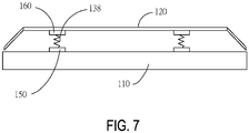
- the buffer members 130 may include a spring 138, an end of the spring 138 is connected to the beam 110, and another end of the spring 138 is connected to the box cover 120 assembly.
- the first end of the spring 138 is connected to a side of the beam 110 close to the box cover 120
- the second end of the spring 138 is connected to a side of the box cover 120 close to the beam 110.
- the battery box may further include: a first connecting member 150 and a second connecting member 160, wherein the first connecting member 150 is connected to the beam 110 and the spring 138; and the second connecting member 160 is connected to the box cover 120 and the spring 138.
- the first connecting member 150 may be a first connecting seat, and the first connecting seat is connected to the beam 110 by one or a plurality of methods of bolting, welding, riveting, and gluing.
- a first mounting portion is disposed on the first connecting seat, and the first end of the spring 138 is connected to the first mounting portion.
- the second connecting member 160 may be a second connecting seat, and the second connecting seat is connected to the box cover 120 by one or a plurality of methods of bolting, welding, riveting, and gluing.
- a second mounting portion is disposed on the first connecting seat, and the second end of the spring 138 is connected to the second mounting portion.
- the box cover 120 is disposed at a side of the beam 110 away from the bottom plate, and the buffer members 130 are respectively connected to the beam 110 and the box cover 120.
- the beam 110 and the box cover 120 are connected via the buffer members 130 to buffer the vibration of the box cover 120, thereby solving the issue that excessive vibration of the box cover 120 damages the box cover 120, so as to improve the service life of the box cover 120.
- Potential damage to the batteries is also avoided when the box cover 120 is vibrated, thus improving the service life of the batteries.
- the batteries are directly placed in the battery compartments, and there is no need to package a plurality of batteries into battery modules and mount them in the battery compartments. Therefore, the number of batteries in the battery compartments may be increased, thereby increasing the energy density of the battery pack.
- the box cover 120 may indirectly be in contact with the batteries during the vibration process, causing the batteries to be damaged.
- the box cover 120 and the beam 110 are connected by the buffer members 130, thus preventing the box cover 120 from damaging the batteries during vibration, and at the same time preventing the box cover 120 from being damaged. Further, the vibration of the box cover 120 may drive the box to vibrate, thus facilitating the mixing of electrolytes in the batteries, thereby facilitating the reaction of the batteries.
- Exemplary embodiments of the disclosure also provide a battery pack.
- the battery pack includes the above battery box and battery assemblies, and the battery assemblies are disposed in the battery box.
- the battery box includes a bottom plate, the beam 110, and the box cover 120.
- the buffer members 130 are disposed between the beam 110 and the box cover 120 and connected to the beam 110 and the box cover 120.
- the battery box may further include the frame 140.
- the frame 140 is disposed at the bottom plate, the frame 140 and the beam 110 form a plurality of battery compartments on the bottom plate, and each of the battery compartments is provided with one battery assembly.
- the battery assemblies include at least two batteries, and the at least two batteries are sequentially arranged at the battery compartments.
- a connecting adhesive layer may be disposed between adjacent batteries in the at least two batteries, and a plurality of batteries may be bonded by the connecting adhesive layer.
- the battery pack provided by an embodiment of the disclosure includes a battery box.
- the box cover 120 is disposed at a side of the beam 110 away from the bottom plate, and the buffer members 130 are respectively connected to the beam 110 and the box cover 120.
- the beam 110 and the box cover 120 are connected via the buffer members 130 to buffer the vibration of the box cover 120, thereby solving the issue that excessive vibration of the box cover 120 damages the box cover 120, so as to improve the service life of the box cover 120. Potential damage to the batteries is also avoided when the box cover 120 is vibrated, thus improving the service life of the batteries.
- An embodiment of the disclosure also provides a vehicle.
- the vehicle may be an electric vehicle.
- the vehicle includes the above battery pack, and the electric vehicle is provided with energy via the battery pack.
- the battery pack includes a battery box and battery assemblies, and the battery assemblies are disposed in the battery box.
- the battery box includes a bottom plate, the beam 110, the frame 140, and the box cover 120.
- the buffer members 130 are disposed between the beam 110 and the box cover 120, and are connected to the beam 110 and the box cover 120.
- the frame 140 is disposed at the bottom plate, the frame 140 and the beam 110 form a plurality of battery compartments on the bottom plate, and each of the battery compartments is provided with one battery assembly.
- a vehicle provided by an embodiment of the disclosure includes a battery box.
- the box cover 120 is disposed at a side of the beam 110 away from the bottom plate, and the buffer members 130 are connected to the beam 110.
- the buffer members 130 between the beam 110 and the box cover 120 may buffer the vibration of the box cover 120 to improve safety, and solve the issue that excessive vibration of the box cover 120 damages the box cover 120, so as to improve the service life of the box cover 120. Potential damage to the batteries from the box cover 120 during vibration is also avoided, thus improving the service life of the batteries.
Landscapes
- Chemical & Material Sciences (AREA)
- Engineering & Computer Science (AREA)
- Chemical Kinetics & Catalysis (AREA)
- Electrochemistry (AREA)
- General Chemical & Material Sciences (AREA)
- Manufacturing & Machinery (AREA)
- Mechanical Engineering (AREA)
- Transportation (AREA)
- Combustion & Propulsion (AREA)
- Life Sciences & Earth Sciences (AREA)
- Sustainable Development (AREA)
- Sustainable Energy (AREA)
- Power Engineering (AREA)
- Aviation & Aerospace Engineering (AREA)
- Battery Mounting, Suspending (AREA)
Abstract
The disclosure relates to the technical field of batteries, in particular to a battery box, a battery pack, and a vehicle. The battery box includes a beam (110), a box cover (120), and a buffer member (130). The buffer member (130) is disposed between the beam (110) and the box cover (120) and the buffer member (130) is connected to the beam (110).
Description
- The disclosure relates to the technical field of batteries, and in particular, to a battery box, a battery pack, and a vehicle.
- With the development and progress of technology, the application of electric vehicles is becoming more and more extensive. The battery is one of the important elements in the electric vehicle. Currently, the battery is usually disposed in a battery box, and the battery box is mounted in the corresponding position of the electric vehicle. The battery box includes a box body and a box cover, etc., and the box cover may be connected to the box body. During the operation of electric vehicles, there is often a larger vibration. The vibration of the vehicle readily causes the box cover to vibrate. The vibration of the box cover affects the structure in the battery box, such as batteries, circuits, etc., and thus causes safety issues.
- It should be mentioned that, the information disclosed in the technical background section above is only used to enhance the understanding of the background of the disclosure, and therefore may include information that does not constitute the prior art known to those having ordinary skill in the art.
- According to the first aspect of the disclosure, a battery box is provided. The battery box includes:
- a beam;
- a box cover;
- a buffer member, wherein the buffer member is disposed between the beam and the box cover and connected to the beam.
- In the battery box provided by an embodiment of the disclosure, the buffer member is disposed between the beam and the box cover, and the buffer member is connected to the beam.
- According to the second aspect of the disclosure, a battery pack is provided. The battery pack includes:
- the above battery box; and
- a battery assembly, wherein the battery assembly is disposed in the battery box.
- The battery pack provided by an embodiment of the disclosure includes the battery box. In the battery box, the buffer member is disposed between the beam and the box cover, and the buffer member is connected to the beam.
- According to the third aspect of the disclosure, a vehicle is provided. The vehicle includes the above battery pack.
- The vehicle provided by an embodiment of the disclosure includes the battery box. In the battery box, the buffer member is disposed between the beam and the box cover, and the buffer member is connected to the beam.
- For a better understanding of the disclosure, reference may be made to exemplary embodiments shown in the following drawings. The components in the drawings are not necessarily to scale and related elements may be omitted, or in some instances proportions may have been exaggerated, so as to emphasize and clearly illustrate the features described herein. In addition, related elements or components can be variously arranged, as known in the art. Further, in the drawings, like reference numerals designate same or like parts throughout the several views.
-
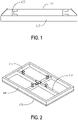
FIG. 1 is a schematic diagram of a first battery box provided by an exemplary embodiment of the disclosure. -
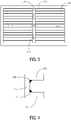
FIG. 2 is a schematic diagram of a second battery box provided by an exemplary embodiment of the disclosure. -
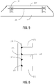
FIG. 3 is a schematic diagram of a battery pack provided by an exemplary embodiment of the disclosure. -
FIG. 4 is a schematic diagram of a buffer member provided by an exemplary embodiment of the disclosure. -
FIG. 5 is a schematic diagram of a third battery box provided by an exemplary embodiment of the disclosure. -
FIG. 6 is a schematic diagram of another buffer member provided by an exemplary embodiment of the disclosure. -
FIG. 7 is a schematic diagram of a fourth battery box provided by an exemplary embodiment of the disclosure. - The technical solutions in the exemplary embodiments of the disclosure will be described clearly and explicitly in conjunction with the drawings in the exemplary embodiments of the disclosure. The description proposed herein is just the exemplary embodiments for the purpose of illustrations only, not intended to limit the scope of the disclosure, so it should be understood that and various modifications and variations could be made thereto without departing from the scope of the disclosure.
- In the description of the present disclosure, unless otherwise specifically defined and limited, the terms "first", "second" and the like are only used for illustrative purposes and are not to be construed as expressing or implying a relative importance. The term "plurality" is two or more. The term "and/or" includes any and all combinations of one or more of the associated listed items.
- In particular, a reference to "the" object or "a" and "an" object is intended to denote also one of a possible plurality of such objects. Unless otherwise defined or described, the terms "connect", "fix" should be broadly interpreted, for example, the term "connect" can be "fixedly connect", "detachably connect", "integrally connect", "electrically connect" or "signal connect". The term "connect" also can be "directly connect" or "indirectly connect via a medium". For the persons skilled in the art, the specific meanings of the abovementioned terms in the present disclosure can be understood according to the specific situation.
- Further, in the description of the present disclosure, it should be understood that spatially relative terms, such as "above", "below" "inside", "outside" and the like, are described based on orientations illustrated in the figures, but are not intended to limit the exemplary embodiments of the present disclosure.
- In the context, it should also be understood that when an element or features is provided "outside" or "inside" of another element(s), it can be directly provided "outside" or "inside" of the other element, or be indirectly provided "outside" or "inside" of the another element(s) by an intermediate element.
- An object of the disclosure is to provide a battery box, a battery pack, and a vehicle, so as to reduce the vibration of the box cover in the battery box at least to a certain extent.
- An exemplary embodiment of the disclosure first provides a battery box. As shown in
FIG. 1 , the battery box includes abeam 110, abox cover 120, andbuffer members 130. Thebuffer members 130 are disposed between thebeam 110 and thebox cover 120 and are connected to thebeam 110. - In the battery box provided by an embodiment of the disclosure, the
box cover 120 is disposed at a side of thebeam 110 away from the bottom plate, and thebuffer members 130 are connected to thebeam 110. Thebuffer members 130 between thebeam 110 and thebox cover 120 may buffer the vibration of thebox cover 120 to improve safety, and solve the issue that excessive vibration of the box cover 120 damages thebox cover 120 to improve the service life of thebox cover 120. Potential damage to the batteries from thebox cover 120 during vibration is also avoided, thus improving the service life of the batteries. - Hereinafter, each portion of the battery box provided by the embodiments of the disclosure is described in detail.
- As shown in
FIG. 2 , in an embodiment of the disclosure, thebeam 110 may be disposed at abottom plate 170, and thebottom plate 170 may be a flat plate structure or a flat plate-like structure. For example, thebottom plate 170 may be a stainless-steel plate, an aluminum alloy plate, etc. An accommodating area is disposed on thebottom plate 170, and the accommodating area is configured to place batteries or battery assemblies. The orthographic projection of the batteries or the battery assemblies on the bottom plate is located in the accommodating area, and the batteries or the battery assemblies may be directly placed in the accommodating area, or other devices may also be disposed between the batteries or the battery assemblies and the bottom plate, such as a cooling device, etc., and the embodiments of the disclosure are not specifically limited in this regard. - As shown in
FIG. 3 , thebottom plate 170 may be provided with aframe 140 and thebeam 110 thereon. Theframe 140 includes a plurality of frame beams. The frame beams are configured to form an accommodating portion for placingbatteries 100. Thebeam 110 is disposed at the accommodating portion. Thebeam 110 divides the accommodating portion into a plurality of battery compartments, each of the battery compartments is provided with a battery pack therein, and the battery pack has a plurality ofbatteries 100. When thebatteries 100 are mounted in the battery compartments, theframe 140 and/or thebeam 110 are connected to thebatteries 100 to withstand at least a portion of the weight of thebatteries 100. - In an embodiment of the disclosure, the
batteries 100 are directly placed in the battery compartments, and there is no need to package a plurality of batteries into battery modules and mount them in the battery compartments. The batteries may be directly in contact with the bottom plate, theframe 140, and thebeam 110. Or the batteries are connected to theframe 140 and thebeam 110 by a connecting method such as a connecting adhesive. Thebeam 110 and theframe 140 withstand at least a portion of the weight of the batteries. - The batteries are placed directly in the battery compartments, thereby increasing the number of batteries in the battery compartments, and thereby increasing the energy density of the battery pack. Since the batteries are directly mounted at the battery compartments, the
box cover 120 may indirectly be in contact with the batteries during the vibration process, thus causing the batteries to be damaged. Thebox cover 120 and thebeam 110 are connected by thebuffer members 130, thus preventing thebox cover 120 from damaging the batteries during vibration, and at the same time preventing thebox cover 120 from being damaged. Further, the vibration of thebox cover 120 may drive the box to vibrate, thus facilitating the mixing of electrolytes in the batteries, and thereby facilitating the reaction of the batteries. - The accommodating area on the bottom plate may be a rectangular structure, the
frame 140 may include four frame beams, and the four frame beams are connected end to end to form a frame. For example, the battery pack may include a first frame beam, a second frame beam, a third frame beam, and a fourth frame beam. The first frame beam, the second frame beam, the third frame beam, and the fourth frame beam are connected end to end and form a frame by welding. - The
beam 110 may be disposed in the frame. Thebeam 110 may include a first beam (a cross beam) and a second beam (vertical beam), and the first beam and the second beam are intersected. For example, the first beam and the second beam are vertically disposed. - In particular, the battery box may include one first beam and one second beam, the first beam and the first frame beam are parallel, and the second beam and the second frame beam are parallel. The first beam and the second beam divide the accommodating area into four battery compartments, and the batteries or the battery assemblies are respectively provided in the four battery compartments. Of course, in practical applications, the number of the first beam and the second beam may also be a plurality, and the embodiments of the disclosure are not limited thereto.
- The
beam 110 and the bottom plate may be connected by welding, and the frame beams and the bottom plate may be connected by welding. The bottom surface of thebeam 110 is in contact with the top surface of the bottom plate, the bottom surface of thebeam 110 is a flat surface, and the top surface of the bottom plate is a flat surface. Therefore, fillet welding may be performed at two sides of thebeam 110 to connect thebeam 110 and the bottom plate. The bottom surface of the frame beams is in contact with the top surface of the bottom plate, the bottom surface of the frame beams is a flat surface, and the top surface of the bottom plate is a flat surface. Therefore, fillet welding may be performed at the outside and inside of the frame beams to connect the frame beams and the bottom plate. - Moreover, in order to improve the connection strength of the
beam 110 and the bottom plate, an adhesive containing groove may be disposed on the bottom plate and/or thebeam 110, and a connecting adhesive layer may be disposed in the adhesive containing groove to connect the bottom plate and thebeam 110. The adhesive containing groove may be disposed at thebeam 110, or the adhesive containing groove may be disposed at the bottom plate, or the adhesive containing groove may be disposed on both the bottom plate and thebeam 110. An adhesive injection channel may be disposed on thebeam 110 or the bottom plate. The adhesive injection channel is configured to communicate with the outside after thebeam 110 and the bottom plate are connected. The adhesive injection channel is connected to the adhesive containing groove. The connecting adhesive layer is disposed in the adhesive containing groove to glue the bottom plate to thebeam 110. - The
buffer members 130 are disposed on thebeam 110, and thebuffer members 130 are located at a side of theinner beam 110 away from the bottom plate. Alternatively, both thebeam 110 and the frame beams may be provided with thebuffer members 130, which is not specifically limited in the embodiments of the disclosure. - For example, a first beam and a second beam are disposed in the
frame 140 formed by the frame beams, and the first beam and the second beam are vertically disposed. A plurality ofbuffer members 130 are disposed on the first beam, and the plurality ofbuffer members 130 may be evenly distributed on the first beam. A plurality ofbuffer members 130 are disposed on the second beam, and the plurality ofbuffer members 130 are evenly distributed at the second beam. - The
buffer members 130 may be connected to thebeam 110. At this time, the end of thebuffer members 130 away from thebeam 110 may provide buffer to thebox cover 120 when thebox cover 120 approaches thebeam 110. Or two ends of thebuffer members 130 may be connected to thebeam 110 and thebox cover 120 respectively. - As an example, the first end of the
buffer members 130 is connected to a side of thebeam 110 close to thebox cover 120 to facilitate the connection of thebuffer members 130 and thebeam 110 and avoid affecting other structures in the battery box. The second end of thebuffer members 130 is connected to a side of thebox cover 120 close to thebeam 110. Thebuffer members 130 are connected to thebeam 110 and thebox cover 120 at the same time, and the buffer effect is better, and thebuffer members 130 are connected to a side of thebox cover 120 close to thebeam 110 to facilitate the connection of thebuffer members 130 and thebox cover 120. - In particular, the
buffer members 130 and thebeam 110 may be connected by one or a plurality of connecting methods of bolting, riveting, welding, and gluing. For example, thebuffer members 130 and thebeam 110 may be connected by a combination of bolting and gluing; or thebuffer members 130 and thebeam 110 may be connected by a combination of riveting and gluing; or thebuffer members 130 and thebeam 110 may be connected by a combination of welding and gluing. - When the
buffer members 130 and thebeam 110 are connected by adhesive, an adhesive containing groove may be disposed on a surface of thebuffer members 130 close to thebeam 110, wherein the adhesive containing groove is filled with a connecting adhesive, and thebuffer members 130 and thebeam 110 are bonded by the connecting adhesive. - When the
buffer members 130 and thebeam 110 are also connected by a bolt, a bolt hole needs to be disposed on thebuffer members 130, and at this time, the adhesive containing groove and the bolt hole are not intersected. That is, the extension path of the adhesive container groove needs to avoid the bolt hole. Or, when thebuffer members 130 and thebeam 110 are also connected by welding, a welding area may be disposed on the edge of thebuffer members 130, and the adhesive containing groove is disposed between the welding areas at two sides of thebuffer members 130. - One or a plurality of connecting areas may be disposed on a side of the
box cover 120 close to the bottom plate, and the connecting areas are configured to be connected to thebuffer members 130. Thebuffer members 130 and thebox cover 120 may be connected by one or a plurality of connecting methods of bolting, riveting, welding, and gluing. For example, thebuffer members 130 and thebox cover 120 may be connected by a combination of bolting and gluing; or thebuffer members 130 and thebox cover 120 may be connected by a combination of riveting and gluing; or thebuffer members 130 and thebox cover 120 may be connected by a combination of welding and gluing. - When the
buffer members 130 and thebox cover 120 are connected by gluing, an adhesive containing groove may be disposed on a surface of thebuffer members 130 close to thebox cover 120, wherein the adhesive containing groove is filled with a connecting adhesive, and thebuffer members 130 and thebox cover 120 are bonded by the connecting adhesive. - In particular, when the
buffer members 130 and thebox cover 120 are also connected by a bolt, a bolt hole needs to be disposed on thebuffer members 130, and at this time, the adhesive containing groove and the bolt hole are not intersected. That is, the extension path of the adhesive container groove needs to avoid the bolt hole. Or, when thebuffer members 130 and thebox cover 120 are also connected by welding, a welding area may be disposed on the edge of thebuffer members 130, and the adhesive containing groove is disposed between the welding areas at two sides of thebuffer members 130. - In a feasible embodiment of the disclosure, as shown in
FIG. 4 , thebuffer members 130 include: a first connectingportion 131, a second connectingportion 132, and abuffer portion 133. The first connectingportion 131 is configured to be connected to thebeam 110; the second connectingportion 132 is configured to be connected to thebox cover 120; an end of thebuffer portion 133 is connected to the first connectingportion 131, and another end of thebuffer portion 133 is connected to the second connectingportion 132. - In particular, a surface of the first connecting
portion 131 close to thebeam 110 may be a flat surface, and the flat surface is in contact with the top surface of thebeam 110. The first connectingportion 131 and thebeam 110 may be connected by a connecting method such as welding, bolting, riveting, or gluing. - A surface of the second connecting
portion 132 close to thebox cover 120 may be a flat surface, and the flat surface is in contact with the top surface of thebeam 110. The first connectingportion 131 and thebeam 110 may be connected by a connecting method such as welding, bolting, riveting, or gluing. - An end of the
buffer portion 133 is connected to the first connectingportion 131, and another end of thebuffer portion 133 is connected to the second connectingportion 132. Thebuffer portion 133 is configured to provide a buffer when thebox cover 120 is vibrated, so as to avoid excessive vibration of thebox cover 120. For example, thebuffer portion 133 may have elasticity. When the force applied to thebuffer members 130 by thebox cover 120 is greater than a preset threshold, thebuffer portion 133 may be elastically deformed, so as to buffer the vibration of thebox cover 120. - The first connecting
portion 131, the second connectingportion 132, and thebuffer portion 133 in thebuffer members 130 may be an integrated structure. For example, the first connectingportion 131, the second connectingportion 132, and thebuffer portion 133 in thebuffer members 130 may be integrally formed by casting or machining. Alternatively, the first connectingportion 131, the second connectingportion 132, and thebuffer portion 133 in thebuffer members 130 may be separate structures. For example, thebuffer portion 133 and the first connectingportion 131 and the second connectingportion 132 may be connected by welding, respectively, or thebuffer portion 133 and the first connectingportion 131 and the second connectingportion 132 may be connected by riveting, respectively, or thebuffer portion 133 and the first connectingportion 131 and the second connectingportion 132 may be connected by a bolt, respectively. Of course, in practical applications, thebuffer portion 133 and the first connectingportion 131 and the second connectingportion 132 may also be connected in other ways, and the embodiments of the disclosure are not limited thereto. - The materials of the first connecting
portion 131, the second connectingportion 132, and thebuffer portion 133 may be the same. For example, the materials of the first connectingportion 131, the second connectingportion 132, and thebuffer portion 133 may be stainless steel, aluminum alloy, etc. When the materials of the first connectingportion 131, the second connectingportion 132, and thebuffer portion 133 are the same, and the first connectingportion 131, the second connectingportion 132, and thebuffer portion 133 are a flat plate structure, the thickness of the first connectingportion 131 is greater than the thickness of thebuffer portion 133, and the thickness of the second connectingportion 132 is greater than the thickness of thebuffer portion 133. The large thickness of the first connectingportion 131 and the second connectingportion 132 may ensure the connection strength of thebuffer members 130 and thebeam 110 and thebuffer portion 133 and thebox cover 120. The small thickness of thebuffer portion 133 may ensure that the stiffness of thebuffer portion 133 is within the preset required range, so that thebuffer portion 133 may be elastically deformed when the box is vibrated. - Alternatively, the materials of the first connecting
portion 131, the second connectingportion 132, and thebuffer portion 133 are different, and the stiffness of the first connectingportion 131 and the second connectingportion 132 is greater than the stiffness of thebuffer portion 133. The large stiffness of the first connectingportion 131 and the second connectingportion 132 may ensure the stability of the connection of thebeam 110 and thebuffer members 130 and thebuffer members 130 and thebox cover 120, and the small stiffness of thebuffer portion 133 may ensure that the stiffness of thebuffer portion 133 is within the preset required range, so that thebuffer portion 133 may be elastically deformed when the box is vibrated. On this basis, when the first connectingportion 131, the second connectingportion 132, and thebuffer portion 133 have a flat plate structure, the thicknesses of the first connectingportion 131, the second connectingportion 132, and thebuffer portion 133 may be the same. The first connectingportion 131, the second connectingportion 132, and thebuffer portion 133 have the same thickness to facilitate manufacture. - In an embodiment of the disclosure, the
buffer members 130 may be, but not limited to, an I-shape, a Z-shape, an L-shape, and the like. - The extending direction of the first connecting
portion 131 is perpendicular to the extending direction of thebuffer portion 133, the extending direction of the second connectingportion 132 is consistent with the extending direction of the first connectingportion 131, the structure is simple, and the buffering effect is good. As an example, the buffer members formed by the first connectingportion 131, the second connectingportion 132, and thebuffer portion 133 are C-shaped. Thebuffer members 130 are C-shaped members having a simple structure, are easy to manufacture, and have a good buffer effect. - It should be mentioned that, in an embodiment of the disclosure, the extending direction of the first connecting
portion 131 and the extending direction of thebuffer portion 133 are disposed perpendicularly. That is, the extending direction of the first connectingportion 131 and the extending direction of thebuffer portion 133 are disposed perpendicularly within the tolerance range allowed by the process. The included angle between the extending direction of the first connectingportion 131 and the extending direction of thebuffer portion 133 is a right angle, or the acute angle between the extending direction of the first connectingportion 131 and the extending direction of thebuffer portion 133 is greater than a predetermined angle threshold. For example, the acute angle between the extending direction of the first connectingportion 131 and the extending direction of thebuffer portion 133 is greater than 89 degrees, 88 degrees, 87 degrees, etc. The extending direction of the second connectingportion 132 is consistent with the extending direction of the first connectingportion 131, meaning that the first connectingportion 131 and the second connectingportion 132 are located at a side of thebuffer portion 133, and the first connectingportion 131 and the second connectingportion 132 are disposed in parallel. The parallel arrangement of the first connectingportion 131 and the second connectingportion 132 means that the extending direction of the first connectingportion 131 and the extending direction of the second connectingportion 132 are parallel within the tolerance range of the process. The acute angle between the extending direction of the first connectingportion 131 and the extending direction of the second connectingportion 132 is smaller than a preset threshold. For example, the acute angle between the extending direction of the first connectingportion 131 and the extending direction of the second connectingportion 132 is less than 3 degrees, 2 degrees, 1 degree, etc. - The
buffer members 130 may be directly connected to thebox cover 120 or thebuffer members 130 may be indirectly connected to thebox cover 120. Thebuffer members 130 and thebox cover 120 may be directly connected by one or a plurality of connecting methods of bolting, riveting, welding, and gluing. - Alternatively, a cold plate may be disposed at a side of the
box cover 120 close to the bottom plate, the cold plate is connected to thebox cover 120, and thebuffer members 130 are connected to the cold plate. The cold plate and thebox cover 120 may be connected by one or a plurality of methods of welding, bolting, riveting, and gluing. Thebuffer members 130 and the cold plate may be connected by one or a plurality of connecting methods of welding, bolting, riveting, and gluing. - For example, a mounting area is disposed on the
box cover 120, and the cold plate is mounted at the mounting area. The mounting area may be a pit on thebox cover 120, and the cold plate is disposed inside the pit. The second connectingportion 132 is connected to the cold plate, and the second connectingportion 132 and the cold plate may be connected by one or a plurality of methods of welding, bolting, riveting, and gluing. - Alternatively, the
box cover 120 may be integrated with a cold plate. For example, a cooling liquid channel is disposed at a side of thebox cover 120 close to thebeam 110, and the batteries are cooled by a cooling liquid in the cooling liquid channel. Alternatively, the cooling liquid channel may also be disposed inside the box cover, which is not specifically limited in the embodiments of the disclosure. - In an embodiment of the disclosure, the
buffer members 130 further include afirst reinforcement portion 135 and asecond reinforcement portion 136, and thefirst reinforcement portion 135 is connected to the first connectingportion 131 and thebuffer portion 133, respectively; and thesecond reinforcement portion 136 is connected to the second connectingportion 132 and thebuffer portion 133, respectively. Thefirst reinforcement portion 135 is configured to improve the connection strength of the first connectingportion 131 and thebuffer portion 133, and thesecond reinforcement portion 136 is configured to improve the connection strength of the first connectingportion 131 and thebuffer portion 133. - In particular, the
first reinforcement portion 135 may be a first reinforcement rib, and the first reinforcement rib is disposed at a portion where the first connectingportion 131 and thebuffer portion 133 are connected. Thesecond reinforcement portion 136 may be a second reinforcement rib, and the second reinforcement rib is disposed at a portion where the second connectingportion 132 and thebuffer portion 133 are connected. - In another feasible embodiment of the disclosure, as shown in
FIG. 5 and FIG. 6 , thebuffer members 130 include: the first connectingportion 131, the second connectingportion 132, the third connectingportion 134, and thebuffer portion 133. The first connectingportion 131 is configured to be connected to thebeam 110; the second connectingportion 132 is configured to be connected to thebox cover 120; an end of thebuffer portion 133 is connected to the first connectingportion 131, and another end of thebuffer portion 133 is connected to the second connectingportion 132. The third connectingportion 134 and thebuffer portion 133 are connected, and the third connectingportion 134 is located between the first connectingportion 131 and the second connectingportion 132. - On this basis, the battery box further includes a cooling member 180 (for example, a cold plate), the cooling
member 180 is disposed between thebeam 110 and thebox cover 120, and the coolingmember 180 is connected to the third connectingportion 134. The coolingmember 180 is restricted by the third connectingportion 134 to avoid vibration of the coolingmember 180. - Of course, in practical applications, the battery box may also include a connecting wire harness, a conductive bar, a connector, etc., and the connecting wire harness, the conductive bar, or the connector may be connected to the third connecting
portion 134, and the embodiments of the disclosure are not limited thereto. - A surface of the first connecting
portion 131 close to thebeam 110 may be a flat surface, and the flat surface is in contact with the top surface of thebeam 110. The first connectingportion 131 and thebeam 110 may be connected by a connecting method such as welding, bolting, riveting, or gluing. A surface of the second connectingportion 132 close to thebox cover 120 may be a flat surface, and the flat surface is in contact with the top surface of thebeam 110. The first connectingportion 131 and thebeam 110 may be connected by a connecting method such as welding, bolting, riveting, or gluing. A surface of the third connectingportion 134 close to thebox cover 120 may be a flat surface, and the flat surface is in contact with the bottom surface of the coolingmember 180. The third connectingportion 134 and thebox cover 120 may be connected by a connecting method such as welding, bolting, riveting, or gluing. - An end of the
buffer portion 133 is connected to the first connectingportion 131, and another end of thebuffer portion 133 is connected to the second connectingportion 132. Thebuffer portion 133 is configured to provide a buffer when thebox cover 120 is vibrated, so as to avoid excessive vibration of thebox cover 120. For example, thebuffer portion 133 may have elasticity. When the force applied to thebuffer members 130 by thebox cover 120 is greater than a preset threshold, thebuffer portion 133 may be elastically deformed, so as to buffer the vibration of thebox cover 120. The third connectingportion 134 and thebuffer portion 133 are connected, the third connectingportion 134 is located between the first connectingportion 131 and the second connectingportion 132, and the third connectingportion 134 is configured to be connected to the coolingmember 180. - The first connecting
portion 131, the second connectingportion 132, the third connectingportion 134, and thebuffer portion 133 in thebuffer members 130 may be an integrated structure. For example, the first connectingportion 131, the second connectingportion 132, the third connectingportion 134, and thebuffer portion 133 in thebuffer members 130 may be integrally formed by casting or machining. Alternatively, the first connectingportion 131, the second connectingportion 132, the third connectingportion 134, and thebuffer portion 133 in thebuffer members 130 may be separate structures. For example, thebuffer portion 133 and the first connectingportion 131, the second connectingportion 132, and the third connectingportion 134 may be connected by welding, respectively, or thebuffer portion 133 and the first connectingportion 131, the second connectingportion 132, and the third connectingportion 134 may be connected by riveting, respectively, or thebuffer portion 133 and the first connectingportion 131, the second connectingportion 132, and the third connectingportion 134 may be connected by a bolt, respectively. Of course, in practical applications, thebuffer portion 133 and the first connectingportion 131, the second connectingportion 132, and the third connectingportion 134 may also be connected in other ways, and the embodiments of the disclosure are not limited thereto. - For example, the second connecting
portion 132 and thebuffer portion 133 may be separate structures. A through hole is disposed on the coolingmember 180, and thebuffer portion 133 penetrates the through hole. The second connectingportion 132 and thebuffer portion 133 are separate structures. During mounting, thebuffer portion 133 may be inserted through a through hole on the cold plate, and then the second connectingportion 132 and thebuffer portion 133 may be connected to facilitate the mounting of the coolingmember 180. The size of the through hole on the cold plate is smaller than the size of the third connectingportion 134, so that the third connectingportion 134 may support the cold plate. - The materials of the first connecting
portion 131, the second connectingportion 132, the third connectingportion 134, and thebuffer portion 133 may be the same. For example, the materials of the first connectingportion 131, the second connectingportion 132, the third connectingportion 134, and thebuffer portion 133 may be stainless steel, aluminum alloy, etc. When the materials of the first connectingportion 131, the second connectingportion 132, the third connectingportion 134, and thebuffer portion 133 are the same, and the first connectingportion 131, the second connectingportion 132, the third connectingportion 134, and thebuffer portion 133 are a flat plate structure, the thickness of the first connectingportion 131 is greater than the thickness of thebuffer portion 133, the thickness of the second connectingportion 132 is greater than the thickness of thebuffer portion 133, and the thickness of the third connectingportion 134 is greater than the thickness of thebuffer portion 133. The large thickness of the first connectingportion 131, the second connectingportion 132, and the third connectingportion 134 may ensure the connection strength of thebuffer members 130 and thebeam 110 and thebuffer portion 133 and thebox cover 120. The small thickness of thebuffer portion 133 may ensure that the stiffness of thebuffer portion 133 is within the preset required range, so that thebuffer portion 133 may be elastically deformed when the box is vibrated. - Alternatively, the materials of the first connecting
portion 131, the second connectingportion 132, the third connectingportion 134, and thebuffer portion 133 are different, and the stiffness of the first connectingportion 131, the second connectingportion 132, and the third connectingportion 134 is greater than the stiffness of thebuffer portion 133. The large stiffness of the first connectingportion 131, the second connectingportion 132, and the third connectingportion 134 may ensure the stability of the connection of thebeam 110 and thebuffer members 130 and thebuffer members 130 and thebox cover 120, and the small stiffness of thebuffer portion 133 may ensure that the stiffness of thebuffer portion 133 is within the preset required range, so that thebuffer portion 133 may be elastically deformed when the box is vibrated. On this basis, when the first connectingportion 131, the second connectingportion 132, the third connectingportion 134, and thebuffer portion 133 have a flat plate structure, the thicknesses of the first connectingportion 131, the second connectingportion 132, the third connectingportion 134, and thebuffer portion 133 may be the same. The first connectingportion 131, the second connectingportion 132, the third connectingportion 134, and thebuffer portion 133 have the same thickness to facilitate manufacture. - The extending direction of the first connecting
portion 131 is perpendicular to the extending direction of thebuffer portion 133, and the extending direction of the second connectingportion 132 and the third connectingportion 134 is consistent with the extending direction of the first connectingportion 131. That is, the first connectingportion 131, the second connectingportion 132, the third connectingportion 134, and thebuffer portion 133 are E-shaped. - It should be mentioned that, in an embodiment of the disclosure, the extending direction of the third connecting
portion 134 is consistent with the extending direction of the first connectingportion 131, meaning that the first connectingportion 131 and the third connectingportion 134 are located at a side of thebuffer portion 133, and the first connectingportion 131 and the third connectingportion 134 are disposed in parallel. The parallel arrangement of the first connectingportion 131 and the third connectingportion 134 means that the extending direction of the first connectingportion 131 and the extending direction of the third connectingportion 134 are parallel within the tolerance range of the process. The acute angle between the extending direction of the first connectingportion 131 and the extending direction of the third connectingportion 134 is smaller than a preset threshold. For example, the acute angle between the extending direction of the first connectingportion 131 and the extending direction of the third connectingportion 134 is less than 3 degrees, 2 degrees, 1 degree, etc. - In an embodiment of the disclosure, the
buffer members 130 further include thefirst reinforcement portion 135, thesecond reinforcement portion 136, and athird reinforcement portion 137. Thefirst reinforcement portion 135 is connected to the first connectingportion 131 and thebuffer portion 133, respectively; thesecond reinforcement portion 136 is connected to the second connectingportion 132 and thebuffer portion 133, respectively; and thethird reinforcement portion 137 is connected to thebuffer portion 133 and the third connectingportion 134, respectively. Thefirst reinforcement portion 135 is configured to improve the connection strength of the first connectingportion 131 and thebuffer portion 133, thesecond reinforcement portion 136 is configured to improve the connection strength of the first connectingportion 131 and thebuffer portion 133, and thesecond reinforcement portion 136 is configured to improve the connection strength of the first connectingportion 131 and thebuffer portion 133. - In particular, the
first reinforcement portion 135 may be a first reinforcement rib, and the first reinforcement rib is disposed at a portion where the first connectingportion 131 and thebuffer portion 133 are connected. Thesecond reinforcement portion 136 may be a second reinforcement rib, and the second reinforcement rib is disposed at a portion where the second connectingportion 132 and thebuffer portion 133 are connected. Thethird reinforcement portion 137 may be a third reinforcement rib, and the third reinforcement rib is disposed at a portion where the third connectingportion 134 and thebuffer portion 133 are connected. - In another feasible embodiment of the disclosure, as shown in
FIG. 7 , thebuffer members 130 may include aspring 138, an end of thespring 138 is connected to thebeam 110, and another end of thespring 138 is connected to thebox cover 120 assembly. In particular, the first end of thespring 138 is connected to a side of thebeam 110 close to thebox cover 120, and the second end of thespring 138 is connected to a side of thebox cover 120 close to thebeam 110. - In order to connect the
spring 138 to thebeam 110 and thebox cover 120, the battery box provided by an embodiment of the disclosure may further include: a first connectingmember 150 and a second connectingmember 160, wherein the first connectingmember 150 is connected to thebeam 110 and thespring 138; and the second connectingmember 160 is connected to thebox cover 120 and thespring 138. For example, the first connectingmember 150 may be a first connecting seat, and the first connecting seat is connected to thebeam 110 by one or a plurality of methods of bolting, welding, riveting, and gluing. A first mounting portion is disposed on the first connecting seat, and the first end of thespring 138 is connected to the first mounting portion. The second connectingmember 160 may be a second connecting seat, and the second connecting seat is connected to thebox cover 120 by one or a plurality of methods of bolting, welding, riveting, and gluing. A second mounting portion is disposed on the first connecting seat, and the second end of thespring 138 is connected to the second mounting portion. - In the battery box provided by an embodiment of the disclosure, the
box cover 120 is disposed at a side of thebeam 110 away from the bottom plate, and thebuffer members 130 are respectively connected to thebeam 110 and thebox cover 120. Thebeam 110 and thebox cover 120 are connected via thebuffer members 130 to buffer the vibration of thebox cover 120, thereby solving the issue that excessive vibration of thebox cover 120 damages thebox cover 120, so as to improve the service life of thebox cover 120. Potential damage to the batteries is also avoided when thebox cover 120 is vibrated, thus improving the service life of the batteries. - Moreover, in an embodiment of the disclosure, the batteries are directly placed in the battery compartments, and there is no need to package a plurality of batteries into battery modules and mount them in the battery compartments. Therefore, the number of batteries in the battery compartments may be increased, thereby increasing the energy density of the battery pack. Since the batteries are directly mounted at the battery compartments, the
box cover 120 may indirectly be in contact with the batteries during the vibration process, causing the batteries to be damaged. Thebox cover 120 and thebeam 110 are connected by thebuffer members 130, thus preventing thebox cover 120 from damaging the batteries during vibration, and at the same time preventing thebox cover 120 from being damaged. Further, the vibration of thebox cover 120 may drive the box to vibrate, thus facilitating the mixing of electrolytes in the batteries, thereby facilitating the reaction of the batteries. - Exemplary embodiments of the disclosure also provide a battery pack. The battery pack includes the above battery box and battery assemblies, and the battery assemblies are disposed in the battery box.
- The battery box includes a bottom plate, the
beam 110, and thebox cover 120. Thebuffer members 130 are disposed between thebeam 110 and thebox cover 120 and connected to thebeam 110 and thebox cover 120. - Further, the battery box may further include the
frame 140. Theframe 140 is disposed at the bottom plate, theframe 140 and thebeam 110 form a plurality of battery compartments on the bottom plate, and each of the battery compartments is provided with one battery assembly. The battery assemblies include at least two batteries, and the at least two batteries are sequentially arranged at the battery compartments. - In particular, a connecting adhesive layer may be disposed between adjacent batteries in the at least two batteries, and a plurality of batteries may be bonded by the connecting adhesive layer.
- The battery pack provided by an embodiment of the disclosure includes a battery box. In the battery box, the
box cover 120 is disposed at a side of thebeam 110 away from the bottom plate, and thebuffer members 130 are respectively connected to thebeam 110 and thebox cover 120. Thebeam 110 and thebox cover 120 are connected via thebuffer members 130 to buffer the vibration of thebox cover 120, thereby solving the issue that excessive vibration of thebox cover 120 damages thebox cover 120, so as to improve the service life of thebox cover 120. Potential damage to the batteries is also avoided when thebox cover 120 is vibrated, thus improving the service life of the batteries. - An embodiment of the disclosure also provides a vehicle. The vehicle may be an electric vehicle. The vehicle includes the above battery pack, and the electric vehicle is provided with energy via the battery pack.
- The battery pack includes a battery box and battery assemblies, and the battery assemblies are disposed in the battery box. The battery box includes a bottom plate, the
beam 110, theframe 140, and thebox cover 120. Thebuffer members 130 are disposed between thebeam 110 and thebox cover 120, and are connected to thebeam 110 and thebox cover 120. Theframe 140 is disposed at the bottom plate, theframe 140 and thebeam 110 form a plurality of battery compartments on the bottom plate, and each of the battery compartments is provided with one battery assembly. - A vehicle provided by an embodiment of the disclosure includes a battery box. In the battery box, the
box cover 120 is disposed at a side of thebeam 110 away from the bottom plate, and thebuffer members 130 are connected to thebeam 110. Thebuffer members 130 between thebeam 110 and thebox cover 120 may buffer the vibration of thebox cover 120 to improve safety, and solve the issue that excessive vibration of thebox cover 120 damages thebox cover 120, so as to improve the service life of thebox cover 120. Potential damage to the batteries from thebox cover 120 during vibration is also avoided, thus improving the service life of the batteries. - Other embodiments of the disclosure will be apparent to those skilled in the art from consideration of the specification and practice of the disclosure disclosed herein. The disclosure is intended to cover any variations, uses or adaptations of the disclosure. These variations, uses, or adaptations follow the general principles of the disclosure and include common general knowledge or conventional technical means in the art that are not disclosed in the present disclosure.
Claims (15)
- A battery box, wherein the battery box comprises:a beam (110);a box cover (120); anda buffer member (130), wherein the buffer member (130) is disposed between the beam (110) and the box cover (120) and connected to the beam (110).
- The battery box of claim 1, wherein a first end of the buffer member (130) is connected to a side of the beam (110) close to the box cover (120).
- The battery box of claim 2, wherein a second end of the buffer member (130) is connected to a side of the box cover (120) close to the beam (110).
- The battery box of claim 1, wherein the buffer member (130) comprises:a first connecting portion (131), wherein the first connecting portion (131) is configured to connect the beam (110);a second connecting portion (132), wherein the second connecting portion (132) is configured to connect the box cover (120); anda buffer portion (133), wherein an end of the buffer portion (133) is connected to the first connecting portion (131), and another end of the buffer portion (133) is connected to the second connecting portion (132).
- The battery box of claim 4, wherein an extending direction of the first connecting portion (131) is perpendicular to an extending direction of the buffer portion (133), and an extending direction of the second connecting portion (132) is consistent with the extending direction of the first connecting portion (131).
- The battery box of claim 5, wherein the buffer member (130) is C-shaped.
- The battery box of claim 4, wherein the buffer member (130) further comprises:
a third connecting portion (134), wherein the third connecting portion (134) is connected to the buffer portion (133), and the third connecting portion (134) is located between the first connecting portion (131) and the second connecting portion (132). - The battery box of claim 7, wherein an extending direction of the first connecting portion (131) is perpendicular to an extending direction of the buffer portion (133), an extending direction of the second connecting portion (132) is consistent with the extending direction of the first connecting portion (131), and an extending direction of the third connecting portion (134) is consistent with the extending direction of the first connecting portion (131) to form an E-shaped buffer member (130).
- The battery box of claim 7, wherein the battery box further comprises:
a cooling member (180), wherein the cooling member (180) is disposed between the beam (110) and the box cover (120), and the cooling member (180) is connected to the third connecting portion (134). - The battery box of any one of claims 4-9, wherein the buffer member (130) further comprises:a first reinforcement portion (135), wherein the first reinforcement portion (135) is respectively connected to the first connecting portion (131) and the buffer portion (133); anda second reinforcement portion (136), wherein the second reinforcement portion (136) is respectively connected to the second connecting portion (132) and the buffer portion (133).
- The battery box of claim 1, wherein the buffer member (130) comprises:
a spring (138), wherein an end of the spring (138) is connected to the beam (110), and another end of the spring (138) is connected to the box cover (120). - The battery box of claim 11, wherein the battery box further comprises:a first connecting member (150), wherein the first connecting member (150) is connected to the beam (110) and the spring (138); anda second connecting member (160), wherein the second connecting member (160) is connected to the box cover (120) and the spring (138).
- The battery box of claim 1, wherein the battery box further comprises:
a frame (140), wherein the frame (140) and the beam (110) form a plurality of battery compartments, and the battery compartments are configured for accommodating batteries, and when the batteries are disposed in the battery compartments, the frame (140) and/or the beam (110) are connected to the batteries to withstand at least a portion of a weight of the batteries. - A battery pack, wherein the battery pack comprises:the battery box of any one of claims 1-13; anda battery assembly, wherein the battery assembly is disposed in the battery box.
- A vehicle, wherein the vehicle comprises the battery pack of claim 14.
Applications Claiming Priority (1)
| Application Number | Priority Date | Filing Date | Title |
|---|---|---|---|
| CN202110529729.8A CN115347303B (en) | 2021-05-14 | 2021-05-14 | Battery box and battery pack, vehicle |
Publications (1)
| Publication Number | Publication Date |
|---|---|
| EP4089795A1 true EP4089795A1 (en) | 2022-11-16 |
Family
ID=77126590
Family Applications (1)
| Application Number | Title | Priority Date | Filing Date |
|---|---|---|---|
| EP21188363.2A Pending EP4089795A1 (en) | 2021-05-14 | 2021-07-29 | Battery box and battery pack, vehicle |
Country Status (3)
| Country | Link |
|---|---|
| US (1) | US11827087B2 (en) |
| EP (1) | EP4089795A1 (en) |
| CN (1) | CN115347303B (en) |
Families Citing this family (2)
| Publication number | Priority date | Publication date | Assignee | Title |
|---|---|---|---|---|
| US20250192298A1 (en) * | 2022-12-01 | 2025-06-12 | Lg Energy Solution, Ltd. | Battery pack |
| CN119208868B (en) * | 2024-11-26 | 2025-02-28 | 常州戴雅托普机械有限公司 | Fast-assembling type solid-state battery package that garden instrument used |
Citations (2)
| Publication number | Priority date | Publication date | Assignee | Title |
|---|---|---|---|---|
| WO2020162123A1 (en) * | 2019-02-04 | 2020-08-13 | Nok株式会社 | Seal structure |
| CN212625888U (en) * | 2020-08-08 | 2021-02-26 | 深圳市凯德旺科技有限公司 | A lithium battery with waterproof function |
Family Cites Families (10)
| Publication number | Priority date | Publication date | Assignee | Title |
|---|---|---|---|---|
| JP3887145B2 (en) * | 2000-05-25 | 2007-02-28 | 矢崎総業株式会社 | Battery cover shock absorption structure |
| CN101887950A (en) * | 2009-05-11 | 2010-11-17 | 深圳富泰宏精密工业有限公司 | Electronic device |
| US9818990B2 (en) * | 2010-08-27 | 2017-11-14 | Samsung Sdi Co., Ltd. | Battery pack with shock absorber |
| CN105947235B (en) * | 2016-05-10 | 2017-05-17 | 国防科学技术大学 | Electric energy and mechanical environment management multifunctional structure |
| CN107768576A (en) * | 2017-11-26 | 2018-03-06 | 惠州市海诚润滑油有限公司 | Elasticity installation buffer structure |
| DE102018210121A1 (en) * | 2018-06-21 | 2019-12-24 | Volkswagen Aktiengesellschaft | Battery housing and motor vehicle with such a battery housing |
| CN208368587U (en) * | 2018-07-17 | 2019-01-11 | 大理华蜀电源科技有限责任公司 | A kind of battery antidetonation Anti-collide shell |
| CN209401705U (en) * | 2019-03-20 | 2019-09-17 | 重庆市育才职业教育中心 | A kind of new-energy automobile battery case |
| US11996576B2 (en) * | 2020-07-03 | 2024-05-28 | Teijin Automotive Technologies, Inc. | Impact resistant frame of battery containment system |
| CN215600464U (en) * | 2021-05-14 | 2022-01-21 | 中航锂电科技有限公司 | Battery box and battery pack, vehicle |
-
2021
- 2021-05-14 CN CN202110529729.8A patent/CN115347303B/en active Active
- 2021-07-26 US US17/384,821 patent/US11827087B2/en active Active
- 2021-07-29 EP EP21188363.2A patent/EP4089795A1/en active Pending
Patent Citations (3)
| Publication number | Priority date | Publication date | Assignee | Title |
|---|---|---|---|---|
| WO2020162123A1 (en) * | 2019-02-04 | 2020-08-13 | Nok株式会社 | Seal structure |
| EP3923366A1 (en) * | 2019-02-04 | 2021-12-15 | NOK Corporation | Seal structure |
| CN212625888U (en) * | 2020-08-08 | 2021-02-26 | 深圳市凯德旺科技有限公司 | A lithium battery with waterproof function |
Also Published As
| Publication number | Publication date |
|---|---|
| CN115347303A (en) | 2022-11-15 |
| CN115347303B (en) | 2025-10-03 |
| US20220363118A1 (en) | 2022-11-17 |
| US11827087B2 (en) | 2023-11-28 |
Similar Documents
| Publication | Publication Date | Title |
|---|---|---|
| CN111937179B (en) | Power supply device and electric vehicle having the same | |
| US12341207B2 (en) | Battery module having module housing of thin plate type and battery pack including the same | |
| EP3401976B1 (en) | Battery pack | |
| US11349164B2 (en) | Battery cooler support architecture | |
| US11827087B2 (en) | Battery box and battery pack, vehicle | |
| WO2022120850A1 (en) | Battery, electric apparatus, and method for manufacturing battery | |
| WO2020135005A1 (en) | Battery pack and vehicle | |
| KR20220073830A (en) | Box body, battery pack and device | |
| US20200303695A1 (en) | Battery module and battery pack | |
| KR20220005395A (en) | Power storage device | |
| US12609400B2 (en) | Battery and power consuming device | |
| US20200287181A1 (en) | Battery Module and Battery Pack | |
| WO2020059296A1 (en) | Power supply device, vehicle having power supply device, and power storage device | |
| EP4345983A1 (en) | Liquid-cooled battery module and battery pack | |
| CN215600464U (en) | Battery box and battery pack, vehicle | |
| KR102836822B1 (en) | Batteries and electrical devices | |
| EP4089820A1 (en) | Battery container, battery pack and battery assembling method | |
| WO2018047851A1 (en) | Battery unit and vehicular storage battery device | |
| EP4120454A1 (en) | Battery pack, assembly process of battery pack and vehicle | |
| US20250062464A1 (en) | Battery, electricity consumption device and method for producing battery | |
| CN222851588U (en) | Battery box, battery pack and vehicle | |
| CN111954941B (en) | Power supply device and electric vehicle having the same | |
| CN219626749U (en) | Lower box structure and battery pack device | |
| CN219226439U (en) | battery device | |
| US11938803B2 (en) | Battery container, battery pack, and vehicle |
Legal Events
| Date | Code | Title | Description |
|---|---|---|---|
| PUAI | Public reference made under article 153(3) epc to a published international application that has entered the european phase |
Free format text: ORIGINAL CODE: 0009012 |
|
| STAA | Information on the status of an ep patent application or granted ep patent |
Free format text: STATUS: REQUEST FOR EXAMINATION WAS MADE |
|
| 17P | Request for examination filed |
Effective date: 20210729 |
|
| AK | Designated contracting states |
Kind code of ref document: A1 Designated state(s): AL AT BE BG CH CY CZ DE DK EE ES FI FR GB GR HR HU IE IS IT LI LT LU LV MC MK MT NL NO PL PT RO RS SE SI SK SM TR |
|
| RAP3 | Party data changed (applicant data changed or rights of an application transferred) |
Owner name: CALB GROUP CO., LTD. |