EP4089654A1 - Paper sheet storage device - Google Patents
Paper sheet storage device Download PDFInfo
- Publication number
- EP4089654A1 EP4089654A1 EP20912567.3A EP20912567A EP4089654A1 EP 4089654 A1 EP4089654 A1 EP 4089654A1 EP 20912567 A EP20912567 A EP 20912567A EP 4089654 A1 EP4089654 A1 EP 4089654A1
- Authority
- EP
- European Patent Office
- Prior art keywords
- support base
- down mechanism
- stage
- storage device
- causes
- Prior art date
- Legal status (The legal status is an assumption and is not a legal conclusion. Google has not performed a legal analysis and makes no representation as to the accuracy of the status listed.)
- Withdrawn
Links
- 230000005540 biological transmission Effects 0.000 claims description 69
- 238000001514 detection method Methods 0.000 description 11
- 238000000926 separation method Methods 0.000 description 7
- 238000010586 diagram Methods 0.000 description 6
- 230000001133 acceleration Effects 0.000 description 5
- 230000000694 effects Effects 0.000 description 4
- 238000000034 method Methods 0.000 description 3
- 230000000630 rising effect Effects 0.000 description 3
- 230000002457 bidirectional effect Effects 0.000 description 1
- 238000004519 manufacturing process Methods 0.000 description 1
Images




Classifications
-
- G—PHYSICS
- G07—CHECKING-DEVICES
- G07D—HANDLING OF COINS OR VALUABLE PAPERS, e.g. TESTING, SORTING BY DENOMINATIONS, COUNTING, DISPENSING, CHANGING OR DEPOSITING
- G07D11/00—Devices accepting coins; Devices accepting, dispensing, sorting or counting valuable papers
- G07D11/10—Mechanical details
- G07D11/16—Handling of valuable papers
-
- B—PERFORMING OPERATIONS; TRANSPORTING
- B65—CONVEYING; PACKING; STORING; HANDLING THIN OR FILAMENTARY MATERIAL
- B65H—HANDLING THIN OR FILAMENTARY MATERIAL, e.g. SHEETS, WEBS, CABLES
- B65H1/00—Supports or magazines for piles from which articles are to be separated
- B65H1/08—Supports or magazines for piles from which articles are to be separated with means for advancing the articles to present the articles to the separating device
- B65H1/14—Supports or magazines for piles from which articles are to be separated with means for advancing the articles to present the articles to the separating device comprising positively-acting mechanical devices
-
- B—PERFORMING OPERATIONS; TRANSPORTING
- B65—CONVEYING; PACKING; STORING; HANDLING THIN OR FILAMENTARY MATERIAL
- B65H—HANDLING THIN OR FILAMENTARY MATERIAL, e.g. SHEETS, WEBS, CABLES
- B65H31/00—Pile receivers
- B65H31/04—Pile receivers with movable end support arranged to recede as pile accumulates
- B65H31/08—Pile receivers with movable end support arranged to recede as pile accumulates the articles being piled one above another
- B65H31/10—Pile receivers with movable end support arranged to recede as pile accumulates the articles being piled one above another and applied at the top of the pile
-
- B—PERFORMING OPERATIONS; TRANSPORTING
- B65—CONVEYING; PACKING; STORING; HANDLING THIN OR FILAMENTARY MATERIAL
- B65H—HANDLING THIN OR FILAMENTARY MATERIAL, e.g. SHEETS, WEBS, CABLES
- B65H83/00—Combinations of piling and depiling operations, e.g. performed simultaneously, of interest apart from the single operation of piling or depiling as such
- B65H83/02—Combinations of piling and depiling operations, e.g. performed simultaneously, of interest apart from the single operation of piling or depiling as such performed on the same pile or stack
- B65H83/025—Combinations of piling and depiling operations, e.g. performed simultaneously, of interest apart from the single operation of piling or depiling as such performed on the same pile or stack onto and from the same side of the pile or stack
-
- G—PHYSICS
- G07—CHECKING-DEVICES
- G07D—HANDLING OF COINS OR VALUABLE PAPERS, e.g. TESTING, SORTING BY DENOMINATIONS, COUNTING, DISPENSING, CHANGING OR DEPOSITING
- G07D11/00—Devices accepting coins; Devices accepting, dispensing, sorting or counting valuable papers
- G07D11/10—Mechanical details
- G07D11/12—Containers for valuable papers
-
- B—PERFORMING OPERATIONS; TRANSPORTING
- B65—CONVEYING; PACKING; STORING; HANDLING THIN OR FILAMENTARY MATERIAL
- B65H—HANDLING THIN OR FILAMENTARY MATERIAL, e.g. SHEETS, WEBS, CABLES
- B65H2403/00—Power transmission; Driving means
- B65H2403/40—Toothed gearings
- B65H2403/41—Rack-and-pinion, cogwheel in cog railway
-
- B—PERFORMING OPERATIONS; TRANSPORTING
- B65—CONVEYING; PACKING; STORING; HANDLING THIN OR FILAMENTARY MATERIAL
- B65H—HANDLING THIN OR FILAMENTARY MATERIAL, e.g. SHEETS, WEBS, CABLES
- B65H2405/00—Parts for holding the handled material
- B65H2405/10—Cassettes, holders, bins, decks, trays, supports or magazines for sheets stacked substantially horizontally
- B65H2405/11—Parts and details thereof
- B65H2405/111—Bottom
- B65H2405/1116—Bottom with means for changing geometry
-
- B—PERFORMING OPERATIONS; TRANSPORTING
- B65—CONVEYING; PACKING; STORING; HANDLING THIN OR FILAMENTARY MATERIAL
- B65H—HANDLING THIN OR FILAMENTARY MATERIAL, e.g. SHEETS, WEBS, CABLES
- B65H2405/00—Parts for holding the handled material
- B65H2405/10—Cassettes, holders, bins, decks, trays, supports or magazines for sheets stacked substantially horizontally
- B65H2405/11—Parts and details thereof
- B65H2405/111—Bottom
- B65H2405/1116—Bottom with means for changing geometry
- B65H2405/11161—Bottom with means for changing geometry by at least a protruding portion arrangement
-
- B—PERFORMING OPERATIONS; TRANSPORTING
- B65—CONVEYING; PACKING; STORING; HANDLING THIN OR FILAMENTARY MATERIAL
- B65H—HANDLING THIN OR FILAMENTARY MATERIAL, e.g. SHEETS, WEBS, CABLES
- B65H2701/00—Handled material; Storage means
- B65H2701/10—Handled articles or webs
- B65H2701/19—Specific article or web
- B65H2701/1912—Banknotes, bills and cheques or the like
Definitions
- the present invention relates to a paper sheet storage device.
- a banknote handling apparatus such as an automated teller machine (ATM) includes a banknote storage device that stores banknotes that are put in.
- ATM automated teller machine
- a type of banknote storage device one whose placement table, on which banknotes are accumulated and placed, is raised and lowered by an up-down mechanism in a storage space, in which banknotes are stored, is known.
- the placement table gradually lowers as banknotes are stored in the storage space and, when the placement table moves to a bottom surface that is a lower end of the storage space, the banknotes, which are stored in the storage space, are full.
- a pickup roller, a carrying roller, and a separation roller, etc., for taking or putting banknotes out of or into the storage space are provided.
- Patent Literature 1 Japanese Laid-open Patent Publication No. 2012-53637
- the placement table in order to increase the amount of banknotes that can be stored in the storage space, it is considered to form the placement table in a small thickness occupying in a direction in which banknotes are stored in the storage space, that is, a direction in which the placement table rises or lowers.
- the level of a placement surface of the placement table lowers in association with the reduction of the thickness of the placement table and therefore, when the placement table is moved by the up-down mechanism to the top position, it is unable to cause the pickup roller, which sends the banknotes on the placement table, to make contact with the banknotes on the placemen surface.
- the up-down mechanism collides with the carrying roller.
- the position of the up-down mechanism is changed in order to avoid interference between the up-down mechanism and the carrying roller, etc., there is a problem that the space, occupied by the up-down mechanism around the placement table, increases and therefore an increase in the whole size of the device is caused.
- the disclosed technique was made in view of the above-described circumstances, and an object of the technique is to provide a leaf storage device that enables an increase in the amount of paper sheets to be stored without increasing the whole size of the paper sheet storage device.
- One aspect of a paper sheet storage device disclosed in the present application includes: a storage space in which paper sheets are stored; a placement table that is provided in the storage space and on which the paper sheets are accumulated and placed; a support base that supports the placement table; a first up-down mechanism that causes the placement table to rise and lower to an up position and a down position with respect to the support base; and a second up-down mechanism that causes the support base to rise and lower in the storage space, wherein the first up-down mechanism includes a rack unit that is provided on the placement table and a pinion unit that causes the rack unit to move.
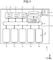
- FIG. 1 is a schematic diagram illustrating a banknote handling apparatus according to an embodiment.
- a banknote handling apparatus 1 of the embodiment includes an in/out unit 11 via which banknotes 6 are put in and taken out; a discrimination unit 12, which discriminates the banknotes 6 that are conveyed from the in/out unit 11; a plurality of temporarily holding units 13, which temporarily store the banknotes 6 that are conveyed from the discrimination unit 12; and a plurality of storage units 14, which store the banknotes 6 that are conveyed from each of the temporarily holding units 13.
- the banknote handling apparatus 1 further includes a conveying mechanism 15, which conveys the banknotes 3 along a conveying path 15a among the units 11, 12, 13 and 14; and a controller 16, which controls each of the units 11, 12, 13 and 14.
- the conveying mechanism 15 includes a conveying belt and a plurality of rollers that form the conveying path 15a along which the banknotes 6 are conveyed, and the conveying belt and the rollers are arranged such that the conveying belt and the rollers connect the in/out unit 11, the discrimination unit 12, each of the temporarily holding units 13, and each of the storage units 14.
- the conveying mechanism 15 is configured to be capable of bidirectional conveying in which the banknote 6 are carried in and out of each of the storage units 14.
- the controller 16 is electrically connected to each of the discrimination unit 12, each of the temporarily holding units 13, each of the storage units 14, and the conveying mechanism 15.
- the storage unit 14 that is installed in the banknote handling apparatus 1 corresponds to a banknote storage device of the embodiment.
- the storage unit 14 will be put into the banknote storage device 14 and will be described below.
- a width direction of the banknote handling apparatus 1 viewed from the side of the in/out unit 11 in FIG. 1 is referred to as an X-direction
- a front-back direction of the banknote handling apparatus 1 is referred to as a Y-direction
- an top-bottom direction of the banknote handling apparatus 1 is referred to as a Z-direction.
- each of the X, Y and Z directions is presented in the drawings after FIG. 1 , too.
- the banknotes 6 are used as an example of paper sheets, paper sheets are not limited to the banknotes 6. Paper sheets include securities, such as a promissory note, a check, a coupon, various instruments, and a share.
- FIG. 2 is a schematic diagram illustrating the banknote storage device 14 of the embodiment.
- FIG. 3 is a perspective view illustrating a state in which a first up-down mechanism of the banknote storage device according to the embodiment causes a stage to rise to an up position.
- FIG. 4 is a perspective view illustrating a state in which the first up-down mechanism of the banknote storage device according to the embodiment causes the stage to lower to a down position.
- the banknote storage device 14 includes a storage space 20 in which the banknotes 6 are stored, and a stage 21 that is provided in the storage space 20 and that serves as a placement table on which the banknotes 6 are accumulated and placed.
- the banknote storage device 14 further includes a support base 22 that supports the stage 21, a first up-down mechanism 23 that causes the stage 21 to rise and lower with respect to the support base 22 to an up position P1 and a down position P2 in the Z-direction; a second up-down mechanism 24 that causes the support base 22 to rise and lower in the Z-direction in the storage space 20; and a drive force transmission mechanism 31 that transmits a drive force to the first up-down mechanism in association with an up-down operation of the second up-down mechanism 24 on the support base 22.
- the stage 21 has a placement surface 21a on which the banknotes 3 are placed and which moves parallelly to the up position P1 and the down position P2 with the placement surface 21a being in a horizontal posture parallel to an X-Y plane.
- the stage 21 when the stage 21 lowers to the down position P2, the stage 21 is mounted on the support base 22.
- the placement surface 21a of the stage 21 moves in the horizontal posture in the top-bottom direction (the Z-direction) between an upper end and a lower end in the storage space 20.
- the banknotes 6 are placed with their long side being oriented along the X-direction.
- the stage 21 is provided with a rack unit 32 that the first up-down mechanism 23 includes and that is described below.
- a conveying roller group including a pickup roller 25, a carrying roller (feed roller) 26, a separation roller 27, an acceleration roller 28, etc., is provided above the storage space 20.
- the banknote storage device 14 carries the banknote 6 into the storage space 20 and carries the banknote 6 out of the storage space 20. Details of the conveying roller group will be described below.
- the X and Y directions are not limited to the horizontal direction, and the Z direction is not limited to the top-bottom direction.
- the side, on which the banknote 6 is taken or put out of or in the storage space 20 is referred to as a front side of the banknote storage device 14, and the opposite side to the front side, is referred to as a back side of the banknote storage device 14.
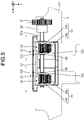
- FIG. 5 is a plane view illustrating the support base 22 and the first up-down mechanism 23 that are arranged in an area S of projection of the stage 21 in the banknote storage device 14 of the embodiment.
- FIG. 5 presents a plane orthogonal to the up-down direction (the Z-direction) in which the second up-down mechanism 24 causes the support base 22 to rise and lower.
- the support base 22 and the first up-down mechanism 23 are arranged in an area S of projection, obtained by projecting the stage 21 on the X-Y plane orthogonal to the up-down direction (the Z-direction) in which the second up-down mechanism 24 causes the support base 22 to rise and lower. Accordingly, the outer size of the support base 22 is formed smaller than the outer size of the stage 21 and is formed in a size within the area S of projection of the stage 21.
- the stage 21, on which the banknotes 6 are placed lowers along the Z-direction between the upper end and the lower end of the storage space 20, because the support base 22 and the first up-down mechanism 23 are arranged in the area S of projection of the stage 21, it is possible to avoid an increase in the size of the banknote storage device 14 because of the support base 22 and the first up-down mechanism 23.
- FIG. 6 is a plane view for describing the first up-down mechanism 23 of the banknote storage device 14 of the embodiment.
- FIG. 7 is a cross-sectional view for describing the first up-down mechanism 23 of the banknote storage device 14 of the embodiment.
- FIG. 7 is a cross section taken along the A-A line in FIG. 6 .
- the first up-down mechanism 23 is arranged on each of both sides of the stage 21 in the X-direction.
- Each of the first up-down mechanism 23 includes a rack unit 32, with which the stage 21 is provided, and a pinion unit 33 that causes the rack unit 32 to move.
- the rack unit 32 includes a first rack 32a and a second rack 32b in a pair that are provided oppositely with the pinion unit 33 being interposed in between.
- the first rack 32a and the second rack 32b are provided under the stage 21 such that the first rack 32a and the second rack 32b are extended along the Z-direction in which the stage 21 rises and lowers.
- the rack unit 32 is arranged movably in an opening 22a of the support base 22 in the Z-direction with respect to the support base 22.
- the pinion unit 33 includes a first pinion 33a and a second pinion 33b in a pair that are engaged with the first rack 32a and the second rack 32b in a pair, respectively.
- the first pinion 33a and the second pinion 33b in a pair are provided in an engaged manner and rotate in synchronization with each other.
- the first pinion 33a and the second pinion 33b are rotatably supported respectively on support shafts 33c with which the support base 22 is provided.
- the first pinion 33a is engaged with a drive gear 58 that the drive force transmission mechanism 31 includes and that will be described below, and a drive force is transmitted by the drive gear 58 to the first pinion 33a.
- the first up-down mechanism 23 includes the first rack 32a and the second rack 32b in a pair, and the first pinion 33a and the second pinion 33b in a pair that are engaged with each other, and thus the up-down operation on the stage 21 is stabilized, and reliability of the up-down operation is increased, and the first up-down mechanism 23 is configured compactly.
- the drive force associated with the up-down operation of the second up-down mechanism 24 is transmitted to the first up-down mechanism 23 via the drive force transmission mechanism 31 to be described below, and therefore the first up-down mechanism 23 causes the stage 21 to rise and lower with respect to the support base 22 simultaneously with the up-down operation in which the second up-down mechanism 24 causes the support base 22 to rise and lower.
- the second up-down mechanism 24 causes the support base 22 to rise and lower in the Z-direction at a constant up-down speed while the first up-down mechanism 23 causes the stage 21 to rise and lower in the Z-direction at a constant up-down speed.
- the first up-down mechanism 23 and the second up-down mechanism 24 operate simultaneously, which makes it possible to stabilize the up-down operation on the stage 21 in the storage space 20.
- the up-down operation on the stage 21 is stabilized, the banknotes 6 are accumulated on the stage 21, and reliability of a carrying operation is increased.
- the first up-down mechanism 23 is configured to cause the stage 21 to move from the up position P1 to the down position P2 before the support base 22, which is lowered by the second up-down mechanism 24, reaches the lower end D of the up-down area M.
- the down operation on the stage 21 with respect to the support base 22 completes before the support base 22 reaches the lower end D of the up-down area M, and the up-down operation on the stage 21 in the storage space 20 is stabilized, and reliability of the up-down operation is increased.
- FIG. 8 is a cross-sectional view of a main part for describing the operation in which the first up-down mechanism 23 of the embodiment causes the stage 21 to rise from the down position P2.
- FIG. 9 is a cross-sectional view of the main part for describing the operation in which the first up-down mechanism 23 of the embodiment causes the stage 21 to lower from the up position P1.
- the first pinion 33a is rotated counterclockwise by the drive gear 58 of the drive force transmission mechanism 31, thereby causing the first rack 32a to rise.
- the first pinion 33a is rotated counterclockwise and accordingly the second pinion 33b is rotated clockwise in synchronization with the first pinion 33a, so that the second rack 32b is caused to rise.
- the first pinion 33a and the second pinion 33b that rotate in synchronization with each other cause the first rack 32a and the second rack 32b to rise, thereby causing the rack unit 32 to rise with respect to the support base 22 and causing the stage 21 to rise from the down position P2.
- the first pinion 33a is rotated clockwise by the drive gear 58 of the drive force transmission mechanism 31, thereby causing the first rack 32a to lower.
- the first pinion 33a is rotated clockwise and accordingly the second pinion 33b is rotated counterclockwise in synchronization with the first pinion 33a, so that the second rack 32b is caused to lower.
- the first pinion 33a and the second pinion 33b that rotate in synchronization with each other cause the first rack 32a and the second rack 32b to lower, thereby causing the rack unit 32 to lower with respect to the support base 22 and causing the stage 21 to lower from the up position P1.
- the second up-down mechanism 24 includes up-down guide members 46 in a pair that guide the support base 22 movably along the up-down direction (the Z-direction), and a drive belt 47 that causes the support base 22 to move in the up-down direction (the Z-direction).
- the second up-down mechanism 24 further includes a pulley (not illustrated in the drawing) around which the drive belt 47 is put; a base support member 49 (refer to FIG. 6 ) that is connected to the support base 22; and a fixation member 50 that fixes the base support member 49 to the drive belt 47.
- the up-down guide members 46 in a pair are arranged on both sides of the support base 22 in the X-direction.
- a rack 46a for driving the drive force transmission mechanism 31 is formed over the up-down area M (refer to FIG. 2 ) of the support base 22 along the Z-direction and also serves as a rack member for transmitting the drive force to the first up-down mechanism.
- the drive belt 47 is arranged along the Z-direction, and the stage 21 is connected to part of the drive belt 47 in a length direction via the fixation member 50 and the base support member 49.
- a detection piece 50a whose position is detected by a lower end sensor 52 to be described below, is formed in the fixation member 50.
- Driving the second up-down mechanism 24 is controlled by the controller 16 of the banknote handling apparatus 1 described above.
- the drive belt 47 of the second up-down mechanism 24 is arranged on the side of the carrying roller 26 with respect the support base 22 in the Y-direction, that is, the side on which the banknotes 6 are carried by the carrying roller 26 and the separation roller 27 from the stage 21.
- the drive belt 47 is arranged in a free space caused under the space for arranging the support structure of the conveying roller group, such as the carrying roller 26 and the separation roller 27, which makes it possible to arrange the second up-down mechanism 24 compactly and reduces the size of the banknote storage device 14.
- each of an upper end sensor 51 that detects an upper end of the banknotes 6 that are accumulated on the stage 21 and the lower end sensor 52 that detects that the stage 21 on which the banknotes 6 are accumulated lowers to the lower end of the storage space 20, is provided in the storage space 20 of the banknote storage device 14.
- the upper end sensor 51 is arranged at the upper end of the storage space 20, and includes a light emitter 51a that emits detection light and a light receiver 51b that receives detection light that is emitted by the light emitter 51a.
- the lower end sensor 52 is arranged at the lower end of the storage space 20, and includes a light emitter 52a that emits detection light and a light receiver 52b that receives the detection light that is emitted by the light emitter 52a.
- the upper end sensor 51 and the lower end sensor 52 are electrically connected to the controller 16, and the controller 16 controls the second up-down mechanism 24 based on respective results of detection by the upper end sensor 51 and the lower end sensor 52.
- the detection light is blocked by the upper end of the banknotes 6 on the stage 21 (the banknote 6 positioned at the top), and thus the controller 16 detects that the banknotes 6, placed on the stage 21, reaches the upper end.
- the controller 16 controls the second up-down mechanism 24 to cause the stage to lower by a given height.
- the detection light is blocked by the detection piece 50a of the fixation member 50 that is connected to the stage 21, and thus the controller 16 detects that the stage 21 is lowered together with the support base 22 to the lower end of the storage space 20.
- the controller 16 determines that the storage space 20 is full of the banknotes 6, and stops driving the second up-down mechanism 24 and the conveying roller group.
- the drive force transmission mechanism 31 includes the up-down guide member 46 that is provided over the up-down area M of the support base 22 and that serves as the rack member, a first transmission gear 55 that is rotated by the rack 46a of the up-down guide member 46, a second transmission gear 56, a third transmission gear 57, and the drive gear 58 that drives the first pinion 33a of the first up-down mechanism 23.
- the first transmission gear 55 is engaged with the rack 46a of the up-down guide member 46, and is provided rotatably on the base support member 49 (refer to FIG. 6 ) via a spindle 55a.
- the second transmission gear 56 includes a large-diameter gear part 56a that is engaged with the first transmission gear 55, and a small-diameter gear part 56b that is engaged with the third transmission gear 57, and the second transmission gear 56 is provided rotatably on the support base 22 via a rotation shaft 56c.
- the second transmission gear 56 that is arranged on the left in FIG. 6 , is engaged with only the first transmission gear 55, and causes the rotation shaft 56c to rotate.
- the third transmission gear 57 is provided rotatably on the support base 22 via a rotation shaft 57a.
- the drive gear 58 is provided on the rotation shaft 57a of the third transmission gear 57, and the drive gear 58 is rotated in association with rotation of the third transmission gear 57.
- the drive gear 58 is engaged with the first pinion 33a of the first up-down mechanism 23.
- the drive force transmission mechanism 31 includes the torque limiter 59 that blocks the drive force that is transmitted to the pinion unit 33.
- the torque limiter 59 is provided on the rotation shaft 57a of the third transmission gear 57, and is arranged near the third transmission gear 57.
- transmission of the drive force to the first pinion 33a of the pinion unit 33 by the third transmission gear 57 and the drive gear 58 is blocked in association with lowering of the support base 22.
- the rack unit 32 and the pinion unit 33 of the first up-down mechanism 23 are prevented from being damaged in the structure in which the support base 22 continues lowering after the stage 21 moves to the down position P2.
- stage 21 may be controlled such that rising to the up position P1 completes before the support base 22 reaches the upper end U of the up-down area M.
- a configuration in which, in association with the rise of the support base 22 after the reach by the stage 21 to the up position P1, the drive force transmitted by the drive force transmission mechanism 31 is blocked by the torque limiter 59 may be taken.
- the third transmission gear 57, the drive gear 58, and the torque limiter 59 of the drive force transmission mechanism 31 are arranged in the projection area S of the stage 21, excluding part of the third transmission gear 57.
- the up-down guide member 46 of the second up-down mechanism 24 also serves as the rack member of the drive force transmission mechanism 31, which simplifies the drive force transmission mechanism 31.
- the drive force transmission mechanism 31 may include a rack member (not illustrated in the drawing) independent of the up-down guide member 46.
- the drive force transmission mechanism 31 transmits the drive force to the pinion unit 33 via the rack 46a, the first transmission gear 55, the second transmission gear 56, the third transmission gear 57 and the drive gear 58.
- the conveying roller group including the pickup roller 25, which sends out the banknote 6 on the stage 21, the carrying roller 26 and the separation roller 27, which separate the banknotes 6 that are sent by the pickup roller 25 one by one and carries the banknote 6, and the acceleration roller 28, which increases the rate of conveying banknotes that are carried from the carrying roller 26, is arranged above the storage space 20.
- the pickup roller 25 is supported on a rotation shaft 25a and is arranged in a position opposed to the placement surface 21a of the stage 21.
- the carrying roller 26 is supported on a rotation shaft 26a and is arranged on the side of one end of the stage 21 in the Y-direction.
- the separation roller 27 is supported on a rotation shaft 27a and is arranged under the carrying roller 26.
- An idler roller (not illustrated in the drawing) is rotatably supported on the rotation shaft 26a of the carrying roller 26, and the idler roller is arranged adjacently to the carrying roller 26.
- a guide roller (not illustrated in the drawing) is provided on the rotation shaft 26a of the carrying roller 26 with an interval between the guide roller and the carrying roller 26.
- a plurality of acceleration rollers 28 are arranged near the carrying roller 26 along the direction in which the banknote 6 is conveyed. Each of the acceleration rollers 28 is supported on the rotation shaft 28a.
- the pickup roller 25, the carrying roller 26, the acceleration roller 28 and the guide roller are driven by the drive mechanism not illustrated in the drawing to rotate.
- the stage 21 is positioned near the upper end of the storage space 20, that is, near the pickup roller 25. At that time, the stage 21 is in a state of being raised by the first up-down mechanism 23 to the up position P1.
- the banknotes 6 are carried by the conveying roller group, which includes the carrying roller 26, etc., into the storage space 20 and, with accumulating of the banknotes 6 on the stage 21, the second up-down mechanism 24 causes the stage 21 to intermittently lower together with the support base 22 based on a result of detection by the upper end sensor 51.
- the second up-down mechanism 24 causes the stage 21 to gradually lower in association with an increase of the banknotes 6 that are accumulated on the stage 21.
- the first up-down mechanism 23 causes the stage 21 to gradually lower from the up position P1 to the down position P2.
- the first up-down mechanism 23 causes the stage 21 to lower to the down position P3 while the second up-down mechanism 24 causes the support base 22 to lower.
- the stage 21, which is lowered by the first up-down mechanism 23, moves to the down position P2, and lowering of the stage 21 stops.
- the second up-down mechanism 24 causes the support base 22 and the stage 21 to lower in a state where the stage 21 lowers to the down position P2.
- the lower end sensor 52 detects the detection piece 50a of the support base 22, and thus lowering of the stage 21 and the support base 22 stops.
- the second up-down mechanism 24 causes the support base 22 to lower, and the first up-down mechanism 23 causes the stage 21 to lower with respect to the support base 22, which enables further accumulating of the banknotes 6 on the stage 21 by the difference in height between the up position P1 and the down position P2.
- the second up-down mechanism 24 When sending out the banknotes 6 that are accumulated on the stage 21 using the conveying roller group, contrary to the above-described operation of lowering the stage 21 and the support base 22, the second up-down mechanism 24 causes the stage 21 to rise from the lower end D of the up-down area M toward the upper end U.
- the first up-down mechanism 23 causes the stage 21 to start rising from the down position P2 to the up position P1.
- the second up-down mechanism 24 causes the support base 22 to rise, and the first up-down mechanism 23 causes the stage 21 to rise gradually toward the up position P1.
- the first up-down mechanism 23 causes the stage 21 to move to the up position P1 and, as illustrated in FIG. 2 , the banknote 6 on the placement surface 21a of the stage 21 appropriately makes contact with the pickup roller 25, and is sent by the pickup roller 25 smoothly to the side of the carrying roller 26 and the separation roller 27.
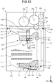
- FIG. 10 is a schematic diagram for describing the banknote storage device of the reference example.
- the structure of a first up-down mechanism of the reference example is different from the first up-down mechanism 23 of the banknote storage device 14 of the embodiment.
- the same components as those of the embodiment are denoted with the same reference numerals as those of the embodiment, and description thereof will be omitted.
- a banknote storage device 114 of the reference example includes a first up-down mechanism 123 including a link mechanism (not illustrated in the drawing) that supports the stage 21 such that the stage 21 can rise and lower with respect to the support base 22; rotation levers 134 in a pair that causes the first up-down mechanism 123 to operate; and a torsion spring 135 that applies a force to the rotation levers 134 to cause the stage 21 to rise to the up position P1.
- the rotation levers 134 are arranged on both sides of the support base 22 in the X-direction, respectively, and a center part of the rotation lever 134 in a length direction is rotatably supported on the support base 22 via a rotation shaft 141.
- a roller 143 is rotatably provided at one end of the rotation lever 134, and the one end of the rotation lever 134 is connected to the stage 21 via the roller 143.
- a guide groove 145, along which the roller 143 at the one end of the rotation lever 134 moves, is formed in the stage 21 along the Y-direction.
- a roller 144 is rotatably provided at the other end of the rotation lever 134, and the roller 144 rotates along and on a guide surface 156 of an operation member 155 with which a bottom surface 20a on the side of the lower end of the storage space 20 is provided.
- the torsion spring 135 is attached to the rotation shaft 141 that supports the center part of the rotation lever 134. An end of the torsion spring 135 is fixed to the support base 22, and the other end is fixed to the rotation lever 134. Accordingly, the torsion spring 135 applies a force such that the rotation lever 134 is caused to rotate around the rotation shaft 141. Accordingly, the state, in which the stage 21 is moved to the torsion spring 135, serves as an initial state.
- the rotation lever 134 causes the stage 21 to move from the up position P1 to the bottom position P2.
- the rotation lever 134 causes the stage 21 to move from the down position P2 to the up position P1.
- the rotation lever 134 and the torsion spring 135 are used, there is a risk that the timing of the operation of causing the stage 21 to rise and lower with respect to the support base 22 is unstable.
- the state, in which the banknotes 6 are accumulated on the stage 21 may vary due to the effect of crumples, folding, etc., of the banknotes 6 that are accumulated on the stage 21.
- the weight applied to the stage 21 varies according to the accumulating state of the banknotes 6 accumulated on the stage 21 and, when the stage 21 separates from the lower end of the storage space 20, there is a risk that the rotation lever 134 does not rotate appropriately.
- elasticity of the torsion spring 135 that causes the rotation lever 134 to rotate has an effect on the operation in which the stage 21 moves from the down position P2 to the up position P1, and it is difficult to appropriately set the elastic force of the torsion spring 135, and the up-down operation on the stage 21 is unstable.
- the elastic force of the torsion spring 135 is large, there is a risk that the stage 21 would not move appropriately to the down position P2.
- the elastic force of the torsion spring 135 is small, there is a risk that the stage 21 would not move appropriately to the up position P1.
- the stage 21 is raised and lowered by the up-down operation using the first rack 32a of the rack unit 32 and the first pinion 33a, and the up-down operation using the second rack 32b and the second pinion 33b without using the torsion spring 135, which makes it possible stabilize the up-down operation and increase reliability of the operation of accumulating and carrying the banknotes 6.
- the rack unit 32 and the pinion unit 33 support the stage 21 such that the stage 21 is able to rise and lower, it is unnecessary to install a complicated link mechanism like that in the reference example, which makes it possible to simplify the first up-down mechanism 23 and simplify the process of manufacturing the banknote storage device 14.
- the banknote storage device 14 of the embodiment includes the first up-down mechanism 23 that causes the stage 21 to rise and lower to the up position P1 and the down position P2 with respect to the support base 22, and the second up-down mechanism that causes the support base 22 to rise and lower in the storage space 20, and the first up-down mechanism 23 includes the rack unit 32 that is provided on the stage 21, and the pinion unit 33 that causes the rack unit 32 to move.
- the rack unit 32 and the pinion unit 33 also serve as the support structure that supports the stage 21 such that the stage 21 can rise and lower, it is possible to avoid the first up-down mechanism 23 from being complicated and increasing in size.
- the stage 21 is raised and lowered by the first up-down mechanism 23 with respect to the support base 22, it is possible to accumulate the banknotes 6 on the stage 21 according to the difference between the up position P1 and the down position P2 of the stage 21. Accordingly, it is possible to increase the amount of the banknotes 6 to be stored in the storage space 20 without increasing the whole size of the paper sheet storage device 14.
- the support base 22 and the first up-down mechanism 23 are arranged in the projection area S obtained by projecting the stage 21 to the X-Y plane orthogonal to the up-down direction in which the second up-down mechanism 24 causes the support base 22 to rise and lower.
- This compared to the structure in which the support base 22 and the first up-down mechanism 23 are arranged outside the space in which the stage 21 rises and lowers, the space, in which the support base 22 and the first up-down mechanism 23 are arranged, makes it possible to avoid the whole size of the banknote storage device 14 from increasing.
- the first up-down mechanism 23 causes the stage 21 to rise and lower with respect to the support base 22 simultaneously with the up-down operation in which the second up-down mechanism 24 raises and lowers the support base 22. Accordingly, it is possible to stabilize the up-down operation on the stage 21 in the storage space 20. For example, compared to the case where each of the first up-down mechanism 23 and the second up-down mechanism 24 independently operates such that lowering of the stage 21 by the first up-down mechanism 23 starts after lowering of the support base 22 by the second up-down mechanism 24 completes, and the up-down operation on the stage 21 is stabilized, and reliability of the operation for accumulating the banknoted on the stage 21 and carrying the banknotes is increased.
- the rack unit 32 includes the first rack 32a and the second rack 32b in a pair that are provided oppositely to each other
- the pinion unit 33 includes the first pinion 33a and the second pinion 33b in a pair that are engaged with the first rack 32a and the second rack 32b in a pair, respectively
- the first pinion 33a and the second pinion 33b are engaged with each other.
- the banknote storage device 14 of the embodiment includes the drive force transmission mechanism 31 that transmits a drive force to the first up-down mechanism 23 using the up-down operation in which the second up-down mechanism 24 causes the support base 22 to rise and lower, and the drive force transmission mechanism 31 includes the up-down guide member 46 including the rack 46a that is provided along the up-down area M of the support base 22 and the first transmission gear 55 that is rotated by the rack 46a of the up-down guide member 46 and thus drives the pinion unit 33 of the first up-down mechanism 23 to cause the pinion unit 33 to rotate.
- This makes it possible to cause the first up-down mechanism 23 to drive using the up-down operation of the second up-down mechanism 24 without using an independent drive source or control for driving the first up-down mechanism 23 and simplify the banknote storage device 14.
- the drive force transmission mechanism 31 includes the torque limiter 59, which blocks the drive force that is transmitted to the pinion unit 33, and the first up-down mechanism 23 causes the stage 21 to move from the up position P1 to the down position P2, before the support base 22, which is lowered by the second up-down mechanism 24, reaches the lower end D of the up-down area M. Accordingly, because the operation of causing the stage 21 to lower with respect to the support base 22 completes before the support base 22 reaches the lower end D of the up-down area M, the up-down operation on the stage 21 in the storage space 20 is stabilized, and reliability of the up-down operation is increased.
Landscapes
- Engineering & Computer Science (AREA)
- Mechanical Engineering (AREA)
- Physics & Mathematics (AREA)
- General Physics & Mathematics (AREA)
- Pile Receivers (AREA)
- Sheets, Magazines, And Separation Thereof (AREA)
Abstract
Description
- The present invention relates to a paper sheet storage device.
- A banknote handling apparatus, such as an automated teller machine (ATM), includes a banknote storage device that stores banknotes that are put in. As this type of banknote storage device, one whose placement table, on which banknotes are accumulated and placed, is raised and lowered by an up-down mechanism in a storage space, in which banknotes are stored, is known.
- In the banknote storage device, the placement table gradually lowers as banknotes are stored in the storage space and, when the placement table moves to a bottom surface that is a lower end of the storage space, the banknotes, which are stored in the storage space, are full. A pickup roller, a carrying roller, and a separation roller, etc., for taking or putting banknotes out of or into the storage space are provided.
- Patent Literature 1:
Japanese Laid-open Patent Publication No. 2012-53637 - In the above-described banknote storage device, in order to increase the amount of banknotes that can be stored in the storage space, it is considered to form the placement table in a small thickness occupying in a direction in which banknotes are stored in the storage space, that is, a direction in which the placement table rises or lowers. In the case where the thickness of the placement table is reduced, the level of a placement surface of the placement table lowers in association with the reduction of the thickness of the placement table and therefore, when the placement table is moved by the up-down mechanism to the top position, it is unable to cause the pickup roller, which sends the banknotes on the placement table, to make contact with the banknotes on the placemen surface. In the case where the level (the top position), to which the placement table can be caused to rise by the up-down mechanism, is extended upward in order to cause the pickup roller to make contact with the banknotes on the placement surface, the up-down mechanism collides with the carrying roller. In the case where the position of the up-down mechanism is changed in order to avoid interference between the up-down mechanism and the carrying roller, etc., there is a problem that the space, occupied by the up-down mechanism around the placement table, increases and therefore an increase in the whole size of the device is caused.
- The disclosed technique was made in view of the above-described circumstances, and an object of the technique is to provide a leaf storage device that enables an increase in the amount of paper sheets to be stored without increasing the whole size of the paper sheet storage device.
- One aspect of a paper sheet storage device disclosed in the present application includes: a storage space in which paper sheets are stored; a placement table that is provided in the storage space and on which the paper sheets are accumulated and placed; a support base that supports the placement table; a first up-down mechanism that causes the placement table to rise and lower to an up position and a down position with respect to the support base; and a second up-down mechanism that causes the support base to rise and lower in the storage space, wherein the first up-down mechanism includes a rack unit that is provided on the placement table and a pinion unit that causes the rack unit to move.
- According to a mode of a paper sheet storage device disclosed by the present application, it is possible to increase the amount of paper sheets to be stored without increasing the whole size of the paper sheet storage device.
-
-
FIG. 1 is a schematic diagram illustrating a banknote handling apparatus according to an embodiment. -
FIG. 2 is a schematic diagram illustrating a banknote storage device according to the embodiment. -
FIG. 3 is a perspective view illustrating a state in which a first up-down mechanism of the banknote storage device according to the embodiment causes a stage to rise to an up position. -
FIG. 4 is a perspective view illustrating a state in which the first up-down mechanism of the banknote storage device according to the embodiment causes the stage to lower to a down position. -
FIG. 5 is a plane view illustrating a support base and the first up-down mechanism that are arranged in an area of projection of the stage in the banknote storage device of the embodiment. -
FIG. 6 is a plane view for describing the first up-down mechanism of the banknote storage device of the embodiment. -
FIG. 7 is a cross-sectional view for describing the first up-down mechanism of the banknote storage device of the embodiment. -
FIG. 8 is a cross-sectional view of a main part for describing an operation in which the first up-down mechanism of the embodiment causes the stage to rise from the down position. -
FIG. 9 is a cross-sectional view of the main part for describing an operation in which the first up-down mechanism of the embodiment causes the stage to lower from the up position. -
FIG. 10 is a schematic diagram for describing a banknote storage device of a reference example. Embodiments for Carrying out the Invention - An embodiment of a paper sheet storage device, disclosed by the present application, will be described in detail below with reference to the drawings. Note that the following embodiment does not limit the paper sheet storage device disclosed by the present application.
-
FIG. 1 is a schematic diagram illustrating a banknote handling apparatus according to an embodiment. As illustrated inFIG. 1 , abanknote handling apparatus 1 of the embodiment includes an in/outunit 11 via whichbanknotes 6 are put in and taken out; adiscrimination unit 12, which discriminates thebanknotes 6 that are conveyed from the in/outunit 11; a plurality of temporarily holdingunits 13, which temporarily store thebanknotes 6 that are conveyed from thediscrimination unit 12; and a plurality ofstorage units 14, which store thebanknotes 6 that are conveyed from each of the temporarily holdingunits 13. - The
banknote handling apparatus 1 further includes aconveying mechanism 15, which conveys the banknotes 3 along aconveying path 15a among theunits controller 16, which controls each of theunits conveying mechanism 15 includes a conveying belt and a plurality of rollers that form theconveying path 15a along which thebanknotes 6 are conveyed, and the conveying belt and the rollers are arranged such that the conveying belt and the rollers connect the in/outunit 11, thediscrimination unit 12, each of the temporarily holdingunits 13, and each of thestorage units 14. Theconveying mechanism 15 is configured to be capable of bidirectional conveying in which thebanknote 6 are carried in and out of each of thestorage units 14. Thecontroller 16 is electrically connected to each of thediscrimination unit 12, each of the temporarily holdingunits 13, each of thestorage units 14, and theconveying mechanism 15. - As illustrated in
FIG. 1 , thestorage unit 14 that is installed in thebanknote handling apparatus 1 corresponds to a banknote storage device of the embodiment. Thestorage unit 14 will be put into thebanknote storage device 14 and will be described below. For convenience of description, a width direction of thebanknote handling apparatus 1 viewed from the side of the in/outunit 11 inFIG. 1 , is referred to as an X-direction, a front-back direction of thebanknote handling apparatus 1, is referred to as a Y-direction, and an top-bottom direction of thebanknote handling apparatus 1, is referred to as a Z-direction. As inFIG. 1 , each of the X, Y and Z directions is presented in the drawings afterFIG. 1 , too. In the present embodiment, thebanknotes 6 are used as an example of paper sheets, paper sheets are not limited to thebanknotes 6. Paper sheets include securities, such as a promissory note, a check, a coupon, various instruments, and a share. -
FIG. 2 is a schematic diagram illustrating thebanknote storage device 14 of the embodiment.FIG. 3 is a perspective view illustrating a state in which a first up-down mechanism of the banknote storage device according to the embodiment causes a stage to rise to an up position.FIG. 4 is a perspective view illustrating a state in which the first up-down mechanism of the banknote storage device according to the embodiment causes the stage to lower to a down position. - As illustrated in
FIG. 2 andFIG. 3 , thebanknote storage device 14 includes astorage space 20 in which thebanknotes 6 are stored, and astage 21 that is provided in thestorage space 20 and that serves as a placement table on which thebanknotes 6 are accumulated and placed. Thebanknote storage device 14 further includes asupport base 22 that supports thestage 21, a first up-down mechanism 23 that causes thestage 21 to rise and lower with respect to thesupport base 22 to an up position P1 and a down position P2 in the Z-direction; a second up-down mechanism 24 that causes thesupport base 22 to rise and lower in the Z-direction in thestorage space 20; and a driveforce transmission mechanism 31 that transmits a drive force to the first up-down mechanism in association with an up-down operation of the second up-down mechanism 24 on thesupport base 22. - The
stage 21 has aplacement surface 21a on which the banknotes 3 are placed and which moves parallelly to the up position P1 and the down position P2 with theplacement surface 21a being in a horizontal posture parallel to an X-Y plane. As illustrated inFIG. 4 , when thestage 21 lowers to the down position P2, thestage 21 is mounted on thesupport base 22. Theplacement surface 21a of thestage 21 moves in the horizontal posture in the top-bottom direction (the Z-direction) between an upper end and a lower end in thestorage space 20. On theplacement surface 21a of thestage 21, as illustrated inFIG. 3 , thebanknotes 6 are placed with their long side being oriented along the X-direction. Thestage 21 is provided with arack unit 32 that the first up-down mechanism 23 includes and that is described below. - As illustrated in
FIG. 2 , a conveying roller group including apickup roller 25, a carrying roller (feed roller) 26, aseparation roller 27, anacceleration roller 28, etc., is provided above thestorage space 20. Using the conveying roller group, thebanknote storage device 14 carries thebanknote 6 into thestorage space 20 and carries thebanknote 6 out of thestorage space 20. Details of the conveying roller group will be described below. - As for the posture of the
banknote storage device 14, the X and Y directions are not limited to the horizontal direction, and the Z direction is not limited to the top-bottom direction. In the embodiment, the side, on which thebanknote 6 is taken or put out of or in thestorage space 20, is referred to as a front side of thebanknote storage device 14, and the opposite side to the front side, is referred to as a back side of thebanknote storage device 14. -
FIG. 5 is a plane view illustrating thesupport base 22 and the first up-down mechanism 23 that are arranged in an area S of projection of thestage 21 in thebanknote storage device 14 of the embodiment.FIG. 5 presents a plane orthogonal to the up-down direction (the Z-direction) in which the second up-down mechanism 24 causes thesupport base 22 to rise and lower. - As illustrated in
FIG. 5 , thesupport base 22 and the first up-down mechanism 23 are arranged in an area S of projection, obtained by projecting thestage 21 on the X-Y plane orthogonal to the up-down direction (the Z-direction) in which the second up-down mechanism 24 causes thesupport base 22 to rise and lower. Accordingly, the outer size of thesupport base 22 is formed smaller than the outer size of thestage 21 and is formed in a size within the area S of projection of thestage 21. - As described above, when the
stage 21, on which thebanknotes 6 are placed, lowers along the Z-direction between the upper end and the lower end of thestorage space 20, because thesupport base 22 and the first up-down mechanism 23 are arranged in the area S of projection of thestage 21, it is possible to avoid an increase in the size of thebanknote storage device 14 because of thesupport base 22 and the first up-down mechanism 23. -
FIG. 6 is a plane view for describing the first up-down mechanism 23 of thebanknote storage device 14 of the embodiment.FIG. 7 is a cross-sectional view for describing the first up-down mechanism 23 of thebanknote storage device 14 of the embodiment.FIG. 7 is a cross section taken along the A-A line inFIG. 6 . - As illustrated in
FIG. 6 and FIG. 7 , the first up-down mechanism 23 is arranged on each of both sides of thestage 21 in the X-direction. Each of the first up-down mechanism 23 includes arack unit 32, with which thestage 21 is provided, and apinion unit 33 that causes therack unit 32 to move. - The
rack unit 32 includes afirst rack 32a and asecond rack 32b in a pair that are provided oppositely with thepinion unit 33 being interposed in between. Thefirst rack 32a and thesecond rack 32b are provided under thestage 21 such that thefirst rack 32a and thesecond rack 32b are extended along the Z-direction in which thestage 21 rises and lowers. As illustrated inFIG. 7 , therack unit 32 is arranged movably in anopening 22a of thesupport base 22 in the Z-direction with respect to thesupport base 22. - The
pinion unit 33 includes afirst pinion 33a and asecond pinion 33b in a pair that are engaged with thefirst rack 32a and thesecond rack 32b in a pair, respectively. Thefirst pinion 33a and thesecond pinion 33b in a pair are provided in an engaged manner and rotate in synchronization with each other. Thefirst pinion 33a and thesecond pinion 33b are rotatably supported respectively onsupport shafts 33c with which thesupport base 22 is provided. Thefirst pinion 33a is engaged with adrive gear 58 that the driveforce transmission mechanism 31 includes and that will be described below, and a drive force is transmitted by thedrive gear 58 to thefirst pinion 33a. As described above, the first up-down mechanism 23 includes thefirst rack 32a and thesecond rack 32b in a pair, and thefirst pinion 33a and thesecond pinion 33b in a pair that are engaged with each other, and thus the up-down operation on thestage 21 is stabilized, and reliability of the up-down operation is increased, and the first up-down mechanism 23 is configured compactly. - The drive force associated with the up-down operation of the second up-
down mechanism 24 is transmitted to the first up-down mechanism 23 via the driveforce transmission mechanism 31 to be described below, and therefore the first up-down mechanism 23 causes thestage 21 to rise and lower with respect to thesupport base 22 simultaneously with the up-down operation in which the second up-down mechanism 24 causes thesupport base 22 to rise and lower. In other words, in thebanknote storage device 14, the second up-down mechanism 24 causes thesupport base 22 to rise and lower in the Z-direction at a constant up-down speed while the first up-down mechanism 23 causes thestage 21 to rise and lower in the Z-direction at a constant up-down speed. - As described above, the first up-
down mechanism 23 and the second up-down mechanism 24 operate simultaneously, which makes it possible to stabilize the up-down operation on thestage 21 in thestorage space 20. For example, after lowering of thesupport base 22 caused by the second up-down mechanism 24 completes, compared to the case where the first up-down mechanism 23 and the second up-down mechanism 24 operate independently such that lowering of thestage 21 caused by the first up-down mechanism 23 starts, the up-down operation on thestage 21 is stabilized, thebanknotes 6 are accumulated on thestage 21, and reliability of a carrying operation is increased. - Furthermore, the first up-
down mechanism 23 is configured to cause thestage 21 to move from the up position P1 to the down position P2 before thesupport base 22, which is lowered by the second up-down mechanism 24, reaches the lower end D of the up-down area M. In other words, the down operation on thestage 21 with respect to thesupport base 22 completes before thesupport base 22 reaches the lower end D of the up-down area M, and the up-down operation on thestage 21 in thestorage space 20 is stabilized, and reliability of the up-down operation is increased. - In other words, in the first up-
down mechanism 23, when thesupport base 22 reaches the upper end U of the up-down area M, rising of thestage 21 with respect to thesupport base 22 completes. Thus, when thesupport base 22 starts lowering from the upper end U of the up-down area M, thestage 21 simultaneously starts lowering with respect to thesupport base 22 from the up position P1 and, after thestage 21 lowers to the down position P2, thesupport base 22 reaches the lower and D of the up-down area M. - As described above, in the first up-
down mechanism 23, because lowering of thestage 21 completes before thesupport base 22 reaches the lower end D of the up-down area M, transmission of the drive force by the driveforce transmission mechanism 31 continues in association with lowering of thesupport base 22. For this reason, in the driveforce transmission mechanism 31, using atorque limiter 59 to be described below blocks transmission of the drive force, which is transmitted by the driveforce transmission mechanism 31 in association with lowering of thesupport base 22, to thefirst pinion 33a of thepinion unit 33. For this reason, in the structure in which thesupport base 22 continues lowering after thestage 21 moves to the down position P2, therack unit 32 and thepinion unit 33 of the first up-down mechanism 23 are prevented from being damaged. -
FIG. 8 is a cross-sectional view of a main part for describing the operation in which the first up-down mechanism 23 of the embodiment causes thestage 21 to rise from the down position P2.FIG. 9 is a cross-sectional view of the main part for describing the operation in which the first up-down mechanism 23 of the embodiment causes thestage 21 to lower from the up position P1. - As illustrated in
FIG. 8 , in the first up-down mechanism 23, thefirst pinion 33a is rotated counterclockwise by thedrive gear 58 of the driveforce transmission mechanism 31, thereby causing thefirst rack 32a to rise. At that time, thefirst pinion 33a is rotated counterclockwise and accordingly thesecond pinion 33b is rotated clockwise in synchronization with thefirst pinion 33a, so that thesecond rack 32b is caused to rise. As described above, in the first up-down mechanism 23, thefirst pinion 33a and thesecond pinion 33b that rotate in synchronization with each other cause thefirst rack 32a and thesecond rack 32b to rise, thereby causing therack unit 32 to rise with respect to thesupport base 22 and causing thestage 21 to rise from the down position P2. - As illustrated in
FIG. 9 , in the first up-down mechanism 23, thefirst pinion 33a is rotated clockwise by thedrive gear 58 of the driveforce transmission mechanism 31, thereby causing thefirst rack 32a to lower. At that time, thefirst pinion 33a is rotated clockwise and accordingly thesecond pinion 33b is rotated counterclockwise in synchronization with thefirst pinion 33a, so that thesecond rack 32b is caused to lower. As described above, in the first up-down mechanism 23, thefirst pinion 33a and thesecond pinion 33b that rotate in synchronization with each other cause thefirst rack 32a and thesecond rack 32b to lower, thereby causing therack unit 32 to lower with respect to thesupport base 22 and causing thestage 21 to lower from the up position P1. - As illustrated in
FIG. 2 , the second up-down mechanism 24 includes up-down guide members 46 in a pair that guide thesupport base 22 movably along the up-down direction (the Z-direction), and adrive belt 47 that causes thesupport base 22 to move in the up-down direction (the Z-direction). The second up-down mechanism 24 further includes a pulley (not illustrated in the drawing) around which thedrive belt 47 is put; a base support member 49 (refer toFIG. 6 ) that is connected to thesupport base 22; and afixation member 50 that fixes thebase support member 49 to thedrive belt 47. - The up-
down guide members 46 in a pair are arranged on both sides of thesupport base 22 in the X-direction. Arack 46a for driving the driveforce transmission mechanism 31 is formed over the up-down area M (refer toFIG. 2 ) of thesupport base 22 along the Z-direction and also serves as a rack member for transmitting the drive force to the first up-down mechanism. Thedrive belt 47 is arranged along the Z-direction, and thestage 21 is connected to part of thedrive belt 47 in a length direction via thefixation member 50 and thebase support member 49. As illustrated inFIG. 2 , adetection piece 50a, whose position is detected by alower end sensor 52 to be described below, is formed in thefixation member 50. Driving the second up-down mechanism 24 is controlled by thecontroller 16 of thebanknote handling apparatus 1 described above. - As illustrated in
FIG. 2 , thedrive belt 47 of the second up-down mechanism 24 is arranged on the side of the carryingroller 26 with respect thesupport base 22 in the Y-direction, that is, the side on which thebanknotes 6 are carried by the carryingroller 26 and theseparation roller 27 from thestage 21. As described above, in thebanknote storage device 14, thedrive belt 47 is arranged in a free space caused under the space for arranging the support structure of the conveying roller group, such as the carryingroller 26 and theseparation roller 27, which makes it possible to arrange the second up-down mechanism 24 compactly and reduces the size of thebanknote storage device 14. - As illustrated in
FIG. 2 , each of anupper end sensor 51 that detects an upper end of thebanknotes 6 that are accumulated on thestage 21 and thelower end sensor 52 that detects that thestage 21 on which thebanknotes 6 are accumulated lowers to the lower end of thestorage space 20, is provided in thestorage space 20 of thebanknote storage device 14. - The
upper end sensor 51 is arranged at the upper end of thestorage space 20, and includes alight emitter 51a that emits detection light and alight receiver 51b that receives detection light that is emitted by thelight emitter 51a. Thelower end sensor 52 is arranged at the lower end of thestorage space 20, and includes alight emitter 52a that emits detection light and alight receiver 52b that receives the detection light that is emitted by thelight emitter 52a. Theupper end sensor 51 and thelower end sensor 52 are electrically connected to thecontroller 16, and thecontroller 16 controls the second up-down mechanism 24 based on respective results of detection by theupper end sensor 51 and thelower end sensor 52. - In the
upper end sensor 51, the detection light is blocked by the upper end of thebanknotes 6 on the stage 21 (thebanknote 6 positioned at the top), and thus thecontroller 16 detects that thebanknotes 6, placed on thestage 21, reaches the upper end. When theupper end sensor 51 senses thebanknote 6 on thestage 21, thecontroller 16 controls the second up-down mechanism 24 to cause the stage to lower by a given height. In thelower end sensor 52, the detection light is blocked by thedetection piece 50a of thefixation member 50 that is connected to thestage 21, and thus thecontroller 16 detects that thestage 21 is lowered together with thesupport base 22 to the lower end of thestorage space 20. When thelower end sensor 52 senses lowering of thestage 21, thecontroller 16 determines that thestorage space 20 is full of thebanknotes 6, and stops driving the second up-down mechanism 24 and the conveying roller group. - As illustrated in
FIGS. 2 ,6 and 7 , the driveforce transmission mechanism 31 includes the up-down guide member 46 that is provided over the up-down area M of thesupport base 22 and that serves as the rack member, afirst transmission gear 55 that is rotated by therack 46a of the up-down guide member 46, asecond transmission gear 56, athird transmission gear 57, and thedrive gear 58 that drives thefirst pinion 33a of the first up-down mechanism 23. - The
first transmission gear 55 is engaged with therack 46a of the up-down guide member 46, and is provided rotatably on the base support member 49 (refer toFIG. 6 ) via aspindle 55a. Thesecond transmission gear 56 includes a large-diameter gear part 56a that is engaged with thefirst transmission gear 55, and a small-diameter gear part 56b that is engaged with thethird transmission gear 57, and thesecond transmission gear 56 is provided rotatably on thesupport base 22 via arotation shaft 56c. Thesecond transmission gear 56 that is arranged on the left inFIG. 6 , is engaged with only thefirst transmission gear 55, and causes therotation shaft 56c to rotate. Thethird transmission gear 57 is provided rotatably on thesupport base 22 via arotation shaft 57a. Thedrive gear 58 is provided on therotation shaft 57a of thethird transmission gear 57, and thedrive gear 58 is rotated in association with rotation of thethird transmission gear 57. Thedrive gear 58 is engaged with thefirst pinion 33a of the first up-down mechanism 23. - The drive
force transmission mechanism 31 includes thetorque limiter 59 that blocks the drive force that is transmitted to thepinion unit 33. Thetorque limiter 59 is provided on therotation shaft 57a of thethird transmission gear 57, and is arranged near thethird transmission gear 57. As described above, in the driveforce transmission mechanism 31, when the second up-down mechanism 24 causes thesupport base 22 to lower in the state in which thestage 21 moves to the down position P2, transmission of the drive force to thefirst pinion 33a of thepinion unit 33 by thethird transmission gear 57 and thedrive gear 58, is blocked in association with lowering of thesupport base 22. For this reason, therack unit 32 and thepinion unit 33 of the first up-down mechanism 23 are prevented from being damaged in the structure in which thesupport base 22 continues lowering after thestage 21 moves to the down position P2. - Note that the
stage 21 may be controlled such that rising to the up position P1 completes before thesupport base 22 reaches the upper end U of the up-down area M. In this case, a configuration in which, in association with the rise of thesupport base 22 after the reach by thestage 21 to the up position P1, the drive force transmitted by the driveforce transmission mechanism 31 is blocked by thetorque limiter 59 may be taken. - As illustrated in
FIG. 5 , thethird transmission gear 57, thedrive gear 58, and thetorque limiter 59 of the driveforce transmission mechanism 31 are arranged in the projection area S of thestage 21, excluding part of thethird transmission gear 57. - In the embodiment, the up-
down guide member 46 of the second up-down mechanism 24 also serves as the rack member of the driveforce transmission mechanism 31, which simplifies the driveforce transmission mechanism 31. Not limited to this structure, the driveforce transmission mechanism 31 may include a rack member (not illustrated in the drawing) independent of the up-down guide member 46. - In the above-described drive
force transmission mechanism 31, when thesupport base 22 is raised and lowed by the second up-down mechanism 24, thefirst transmission gear 55 is rotated by therack 46a of the up-down guide member 46. Thefirst transmission gear 55 is rotated, accordingly thesecond transmission gear 56 is rotated, and accordingly thethird transmission gear 57 is rotated by thesecond transmission gear 56. Thethird transmission gear 57 rotates and accordingly thedrive gear 58 is rotated together with rotation of therotation shaft 57a. Thedrive gear 58 is rotated and accordingly thefirst pinion 33a is rotated. As described above, the driveforce transmission mechanism 31 transmits the drive force to thepinion unit 33 via therack 46a, thefirst transmission gear 55, thesecond transmission gear 56, thethird transmission gear 57 and thedrive gear 58. - As illustrated in
FIG. 2 , the conveying roller group including thepickup roller 25, which sends out thebanknote 6 on thestage 21, the carryingroller 26 and theseparation roller 27, which separate thebanknotes 6 that are sent by thepickup roller 25 one by one and carries thebanknote 6, and theacceleration roller 28, which increases the rate of conveying banknotes that are carried from the carryingroller 26, is arranged above thestorage space 20. - The
pickup roller 25 is supported on arotation shaft 25a and is arranged in a position opposed to theplacement surface 21a of thestage 21. The carryingroller 26 is supported on arotation shaft 26a and is arranged on the side of one end of thestage 21 in the Y-direction. Theseparation roller 27 is supported on arotation shaft 27a and is arranged under the carryingroller 26. An idler roller (not illustrated in the drawing) is rotatably supported on therotation shaft 26a of the carryingroller 26, and the idler roller is arranged adjacently to the carryingroller 26. A guide roller (not illustrated in the drawing) is provided on therotation shaft 26a of the carryingroller 26 with an interval between the guide roller and the carryingroller 26. A plurality ofacceleration rollers 28 are arranged near the carryingroller 26 along the direction in which thebanknote 6 is conveyed. Each of theacceleration rollers 28 is supported on therotation shaft 28a. Thepickup roller 25, the carryingroller 26, theacceleration roller 28 and the guide roller are driven by the drive mechanism not illustrated in the drawing to rotate. - In the
banknote storage device 14 configured as described above, when thebanknotes 6 are not stored in thestorage space 20, thestage 21 is positioned near the upper end of thestorage space 20, that is, near thepickup roller 25. At that time, thestage 21 is in a state of being raised by the first up-down mechanism 23 to the up position P1. Thebanknotes 6 are carried by the conveying roller group, which includes the carryingroller 26, etc., into thestorage space 20 and, with accumulating of thebanknotes 6 on thestage 21, the second up-down mechanism 24 causes thestage 21 to intermittently lower together with thesupport base 22 based on a result of detection by theupper end sensor 51. The second up-down mechanism 24 causes thestage 21 to gradually lower in association with an increase of thebanknotes 6 that are accumulated on thestage 21. - Simultaneously with the operation in which the second up-
down mechanism 24 causes thesupport base 22 to lower, the first up-down mechanism 23 causes thestage 21 to gradually lower from the up position P1 to the down position P2. In thebanknote storage device 14, with an increase of thebanknotes 6 accumulated on thestage 21, the first up-down mechanism 23 causes thestage 21 to lower to the down position P3 while the second up-down mechanism 24 causes thesupport base 22 to lower. - When the
support base 22, which is lowered by the second up-down mechanism 24, lowers to a given position near the lower end D of the up-down area M, thestage 21, which is lowered by the first up-down mechanism 23, moves to the down position P2, and lowering of thestage 21 stops. Subsequently, with an increase of thebanknotes 6 accumulated on thestage 21, the second up-down mechanism 24 causes thesupport base 22 and thestage 21 to lower in a state where thestage 21 lowers to the down position P2. When the second up-down mechanism 24 causes thesupport base 22 to move to the lower end D of the up-down area M, thelower end sensor 52 detects thedetection piece 50a of thesupport base 22, and thus lowering of thestage 21 and thesupport base 22 stops. - As described above, the second up-
down mechanism 24 causes thesupport base 22 to lower, and the first up-down mechanism 23 causes thestage 21 to lower with respect to thesupport base 22, which enables further accumulating of thebanknotes 6 on thestage 21 by the difference in height between the up position P1 and the down position P2. - When sending out the
banknotes 6 that are accumulated on thestage 21 using the conveying roller group, contrary to the above-described operation of lowering thestage 21 and thesupport base 22, the second up-down mechanism 24 causes thestage 21 to rise from the lower end D of the up-down area M toward the upper end U. When thesupport base 22, which is raised by the second up-down mechanism 24, rises to a given position close to the lower end D of the up-down area M, the first up-down mechanism 23 causes thestage 21 to start rising from the down position P2 to the up position P1. Thereafter, in thebanknote storage device 14, the second up-down mechanism 24 causes thesupport base 22 to rise, and the first up-down mechanism 23 causes thestage 21 to rise gradually toward the up position P1. - When he second up-
down mechanism 24 causes thesupport base 22 to move to the upper end U of the up-down area M, the first up-down mechanism 23 causes thestage 21 to move to the up position P1 and, as illustrated inFIG. 2 , thebanknote 6 on theplacement surface 21a of thestage 21 appropriately makes contact with thepickup roller 25, and is sent by thepickup roller 25 smoothly to the side of the carryingroller 26 and theseparation roller 27. - The
banknote storage device 14 of the embodiment will be described in comparison with a banknote storage device of a reference example that solves the problem of the present invention.FIG. 10 is a schematic diagram for describing the banknote storage device of the reference example. In the banknote storage device of the reference example, the structure of a first up-down mechanism of the reference example is different from the first up-down mechanism 23 of thebanknote storage device 14 of the embodiment. In the reference example, the same components as those of the embodiment are denoted with the same reference numerals as those of the embodiment, and description thereof will be omitted. - As illustrated in
FIG. 10 , abanknote storage device 114 of the reference example includes a first up-downmechanism 123 including a link mechanism (not illustrated in the drawing) that supports thestage 21 such that thestage 21 can rise and lower with respect to thesupport base 22; rotation levers 134 in a pair that causes the first up-downmechanism 123 to operate; and atorsion spring 135 that applies a force to the rotation levers 134 to cause thestage 21 to rise to the up position P1. - The rotation levers 134 are arranged on both sides of the
support base 22 in the X-direction, respectively, and a center part of therotation lever 134 in a length direction is rotatably supported on thesupport base 22 via arotation shaft 141. Aroller 143 is rotatably provided at one end of therotation lever 134, and the one end of therotation lever 134 is connected to thestage 21 via theroller 143. Aguide groove 145, along which theroller 143 at the one end of therotation lever 134 moves, is formed in thestage 21 along the Y-direction. Aroller 144 is rotatably provided at the other end of therotation lever 134, and theroller 144 rotates along and on aguide surface 156 of anoperation member 155 with which abottom surface 20a on the side of the lower end of thestorage space 20 is provided. - The
torsion spring 135 is attached to therotation shaft 141 that supports the center part of therotation lever 134. An end of thetorsion spring 135 is fixed to thesupport base 22, and the other end is fixed to therotation lever 134. Accordingly, thetorsion spring 135 applies a force such that therotation lever 134 is caused to rotate around therotation shaft 141. Accordingly, the state, in which thestage 21 is moved to thetorsion spring 135, serves as an initial state. - In the first up-down
mechanism 123 of the reference example, when thestage 21 moves close to the lower end of thestorage space 20, therotation lever 134 causes thestage 21 to move from the up position P1 to the bottom position P2. In the first up-downmechanism 123, when thestage 21 moves apart from the lower end of thestorage space 20, therotation lever 134 causes thestage 21 to move from the down position P2 to the up position P1. - In the
banknote storage device 114 of the reference example, because therotation lever 134 and thetorsion spring 135 are used, there is a risk that the timing of the operation of causing thestage 21 to rise and lower with respect to thesupport base 22 is unstable. For example, the state, in which thebanknotes 6 are accumulated on thestage 21, may vary due to the effect of crumples, folding, etc., of thebanknotes 6 that are accumulated on thestage 21. In such a case, the weight applied to thestage 21 varies according to the accumulating state of thebanknotes 6 accumulated on thestage 21 and, when thestage 21 separates from the lower end of thestorage space 20, there is a risk that therotation lever 134 does not rotate appropriately. - For example, in the case where rotation of the
rotation lever 134 is insufficient when thestage 21 separates from the lower end of thestorage space 20, theroller 144 of therotation lever 134 separates from theoperation members 155 at the lower end of thestorage space 20 before thestage 21 moves to the up position P1, and there is a risk that therotation lever 134 rotate suddenly when thesupport base 22 is raised by the second up-down mechanism 24. At that time, because thestage 21 suddenly moves to the up position P1, thebanknotes 6 on thestage 21 are pressed strongly by thepickup roller 25, and the operation of carrying thebanknote 6 is unstable. - In the
banknote storage device 114 of the reference example, elasticity of thetorsion spring 135 that causes therotation lever 134 to rotate, has an effect on the operation in which thestage 21 moves from the down position P2 to the up position P1, and it is difficult to appropriately set the elastic force of thetorsion spring 135, and the up-down operation on thestage 21 is unstable. In other words, when the elastic force of thetorsion spring 135 is large, there is a risk that thestage 21 would not move appropriately to the down position P2. When the elastic force of thetorsion spring 135 is small, there is a risk that thestage 21 would not move appropriately to the up position P1. - On the other hand, in the
banknote storage device 14 of the embodiment, compared to the above-described reference example, thestage 21 is raised and lowered by the up-down operation using thefirst rack 32a of therack unit 32 and thefirst pinion 33a, and the up-down operation using thesecond rack 32b and thesecond pinion 33b without using thetorsion spring 135, which makes it possible stabilize the up-down operation and increase reliability of the operation of accumulating and carrying thebanknotes 6. Additionally, in thebanknote storage device 14 of the embodiment, because therack unit 32 and thepinion unit 33 support thestage 21 such that thestage 21 is able to rise and lower, it is unnecessary to install a complicated link mechanism like that in the reference example, which makes it possible to simplify the first up-down mechanism 23 and simplify the process of manufacturing thebanknote storage device 14. - As described above, the
banknote storage device 14 of the embodiment includes the first up-down mechanism 23 that causes thestage 21 to rise and lower to the up position P1 and the down position P2 with respect to thesupport base 22, and the second up-down mechanism that causes thesupport base 22 to rise and lower in thestorage space 20, and the first up-down mechanism 23 includes therack unit 32 that is provided on thestage 21, and thepinion unit 33 that causes therack unit 32 to move. As described above, in the first up-down mechanism 23, because thestage 21 is raised and lowered using therack unit 32 and thepinion unit 33, and thus therack unit 32 and thepinion unit 33 also serve as the support structure that supports thestage 21 such that thestage 21 can rise and lower, it is possible to avoid the first up-down mechanism 23 from being complicated and increasing in size. Additionally, because thestage 21 is raised and lowered by the first up-down mechanism 23 with respect to thesupport base 22, it is possible to accumulate thebanknotes 6 on thestage 21 according to the difference between the up position P1 and the down position P2 of thestage 21. Accordingly, it is possible to increase the amount of thebanknotes 6 to be stored in thestorage space 20 without increasing the whole size of the papersheet storage device 14. - In the
banknote storage device 14 of the embodiment, thesupport base 22 and the first up-down mechanism 23 are arranged in the projection area S obtained by projecting thestage 21 to the X-Y plane orthogonal to the up-down direction in which the second up-down mechanism 24 causes thesupport base 22 to rise and lower. This, compared to the structure in which thesupport base 22 and the first up-down mechanism 23 are arranged outside the space in which thestage 21 rises and lowers, the space, in which thesupport base 22 and the first up-down mechanism 23 are arranged, makes it possible to avoid the whole size of thebanknote storage device 14 from increasing. - In the
banknote storage device 14 of the embodiment, the first up-down mechanism 23 causes thestage 21 to rise and lower with respect to thesupport base 22 simultaneously with the up-down operation in which the second up-down mechanism 24 raises and lowers thesupport base 22. Accordingly, it is possible to stabilize the up-down operation on thestage 21 in thestorage space 20. For example, compared to the case where each of the first up-down mechanism 23 and the second up-down mechanism 24 independently operates such that lowering of thestage 21 by the first up-down mechanism 23 starts after lowering of thesupport base 22 by the second up-down mechanism 24 completes, and the up-down operation on thestage 21 is stabilized, and reliability of the operation for accumulating the banknoted on thestage 21 and carrying the banknotes is increased. - In the first up-
down mechanism 23 of thebanknote storage device 14 of the embodiment, therack unit 32 includes thefirst rack 32a and thesecond rack 32b in a pair that are provided oppositely to each other, thepinion unit 33 includes thefirst pinion 33a and thesecond pinion 33b in a pair that are engaged with thefirst rack 32a and thesecond rack 32b in a pair, respectively, and thefirst pinion 33a and thesecond pinion 33b are engaged with each other. This makes it possible to stabilize the up-down operation on thestage 21, and thus increase the reliability of the up-down operation, and configure the first up-down mechanism 23 compactly. - The
banknote storage device 14 of the embodiment includes the driveforce transmission mechanism 31 that transmits a drive force to the first up-down mechanism 23 using the up-down operation in which the second up-down mechanism 24 causes thesupport base 22 to rise and lower, and the driveforce transmission mechanism 31 includes the up-down guide member 46 including therack 46a that is provided along the up-down area M of thesupport base 22 and thefirst transmission gear 55 that is rotated by therack 46a of the up-down guide member 46 and thus drives thepinion unit 33 of the first up-down mechanism 23 to cause thepinion unit 33 to rotate. This makes it possible to cause the first up-down mechanism 23 to drive using the up-down operation of the second up-down mechanism 24 without using an independent drive source or control for driving the first up-down mechanism 23 and simplify thebanknote storage device 14. - In the
banknote storage device 14 of the embodiment, the driveforce transmission mechanism 31 includes thetorque limiter 59, which blocks the drive force that is transmitted to thepinion unit 33, and the first up-down mechanism 23 causes thestage 21 to move from the up position P1 to the down position P2, before thesupport base 22, which is lowered by the second up-down mechanism 24, reaches the lower end D of the up-down area M. Accordingly, because the operation of causing thestage 21 to lower with respect to thesupport base 22 completes before thesupport base 22 reaches the lower end D of the up-down area M, the up-down operation on thestage 21 in thestorage space 20 is stabilized, and reliability of the up-down operation is increased. It is also possible to, using thetorque limiter 59, block transmission of the drive force that is transmitted by the driveforce transmission mechanism 31 in association with lowering of thesupport base 22 after thestage 21 moves to the down position P2 to thepinion unit 33. Thus, when thesupport base 22 continues lowering after thestage 21 moves to the down position P2, it is possible to prevent therack unit 32 and thepinion unit 33 of the first up-down mechanism 23 from being damaged. -
- 1
- BANKNOTE HANDLING APPARATUS
- 6
- BANKNOTE (PAPER SHEET)
- 14
- BANKNOTE STORAGE DEVICE (PAPER SHEET STORAGE DEVICE)
- 20
- STORAGE SPACE
- 21
- STAGE (PLACEMENT TABLE)
- 22
- SUPPORT BASE
- 23
- FIRST UP-DOWN MECHANISM
- 24
- SECOND UP-DOWN MECHANISM
- 31
- DRIVE FORCE TRANSMISSION MECHANISM
- 32
- RACK UNIT
- 32a
- FIRST RACK (RACK)
- 32b
- SECOND RACK (RACK)
- 33
- PINION UNIT
- 33a
- FIRST PINION (PINION)
- 33b
- SECOND PINION (PINION)
- 46
- UP-DOWN GUIDE MEMBER (RACK MEMBER)
- 46a
- RACK
- 49
- BASE SUPPORT MEMBER
- 55
- FIRST TRANSMISSION GEAR (TRANSMISSION GEAR)
- 56
- SECOND TRANSMISSION GEAR (TRANSMISSION GEAR)
- 57
- THIRD TRANSMISSION GEAR (TRANSMISSION GEAR)
- 58
- DRIVE GEAR (TRANSMISSION GEAR)
- 59
- TORQUE LIMITER
- D
- LOWER END
- U
- UPPER END
- M
- UP-DOWN AREA
- P1
- UP POSITION
- P2
- DOWN POSITION
- S
- AREA OF PROJECTION
Claims (6)
- A paper sheet storage device comprising:a storage space in which paper sheets are stored;a placement table that is provided in the storage space and on which the paper sheets are accumulated and placed;a support base that supports the placement table;a first up-down mechanism that causes the placement table to rise and lower to an up position and a down position with respect to the support base; anda second up-down mechanism that causes the support base to rise and lower in the storage space,wherein the first up-down mechanism includes a rack unit that is provided on the placement table and a pinion unit that causes the rack unit to move.
- The paper sheet storage device according to claim 1, wherein the support base and the first up-down mechanism are arranged in a projection area in which the placement table is projected on a plane orthogonal to an up-down direction in which the second up-down mechanism causes the support base to rise and lower.
- The paper sheet storage device according to claim 1, wherein the first up-down mechanism causes the placement table to rise and lower with respect to the support base simultaneously with an up-down operation in which the second up-down mechanism causes the support base to rise or lower.
- The paper sheet storage device according to claim 1, wherein the rack unit includes racks in a pair that are provided oppositely to each other, and
the pinion unit includes pinions in a pair that are engaged with the racks in a pair, respectively, and the pinions in a pair are engaged with each other. - The paper sheet storage device according to claim 1, further comprising a drive force transmission mechanism that transmits a drive force to the first up-down mechanism using an up-down operation in which the second up-down mechanism causes the support base to rise and lower,
wherein the drive force transmission mechanism includes a rack member that is provided over an up-down area of the support base and a transmission gear that is rotated by the rack member and drives the pinion unit of the first up-down mechanism to cause the pinion unit to rotate. - The paper sheet storage device according to claim 5, wherein the drive force transmission mechanism includes a torque limiter that blocks the drive force that is transmitted to the pinion unit, and
the first up-down mechanism causes the placement table to move from the up position to the down position before the support base that is lowered by the second up-down mechanism reaches a lower end of the up-down area.
Applications Claiming Priority (1)
| Application Number | Priority Date | Filing Date | Title |
|---|---|---|---|
| PCT/JP2020/000090 WO2021140549A1 (en) | 2020-01-06 | 2020-01-06 | Paper sheet storage device |
Publications (2)
| Publication Number | Publication Date |
|---|---|
| EP4089654A1 true EP4089654A1 (en) | 2022-11-16 |
| EP4089654A4 EP4089654A4 (en) | 2022-12-28 |
Family
ID=76787996
Family Applications (1)
| Application Number | Title | Priority Date | Filing Date |
|---|---|---|---|
| EP20912567.3A Withdrawn EP4089654A4 (en) | 2020-01-06 | 2020-01-06 | Paper sheet storage device |
Country Status (3)
| Country | Link |
|---|---|
| EP (1) | EP4089654A4 (en) |
| JP (1) | JPWO2021140549A1 (en) |
| WO (1) | WO2021140549A1 (en) |
Families Citing this family (1)
| Publication number | Priority date | Publication date | Assignee | Title |
|---|---|---|---|---|
| AU2022320805B2 (en) * | 2021-07-28 | 2025-08-28 | Crane Payment Innovations, Inc. | Multi-mode bulk banknote feeder |
Family Cites Families (4)
| Publication number | Priority date | Publication date | Assignee | Title |
|---|---|---|---|---|
| JP2744551B2 (en) * | 1992-05-28 | 1998-04-28 | 沖電気工業株式会社 | Paper storage box |
| JP4060060B2 (en) * | 2001-11-14 | 2008-03-12 | グローリー株式会社 | Paper sheet processing equipment |
| KR101114727B1 (en) * | 2009-12-31 | 2012-02-29 | 노틸러스효성 주식회사 | Push plate up and down device in bill stacking box |
| JP5561035B2 (en) | 2010-08-31 | 2014-07-30 | 沖電気工業株式会社 | Paper sheet storage device |
-
2020
- 2020-01-06 EP EP20912567.3A patent/EP4089654A4/en not_active Withdrawn
- 2020-01-06 JP JP2021569616A patent/JPWO2021140549A1/ja active Pending
- 2020-01-06 WO PCT/JP2020/000090 patent/WO2021140549A1/en not_active Ceased
Also Published As
| Publication number | Publication date |
|---|---|
| EP4089654A4 (en) | 2022-12-28 |
| JPWO2021140549A1 (en) | 2021-07-15 |
| WO2021140549A1 (en) | 2021-07-15 |
Similar Documents
| Publication | Publication Date | Title |
|---|---|---|
| US4822018A (en) | Sheet handling apparatus | |
| JP2019147671A (en) | Image reading device | |
| KR101085379B1 (en) | Banknote accumulator | |
| JP2636252B2 (en) | Document distribution machine | |
| KR100868715B1 (en) | Paper feeding device | |
| US10841444B2 (en) | Image reading apparatus | |
| US10513402B2 (en) | Sheet feeding apparatus | |
| WO2021140549A1 (en) | Paper sheet storage device | |
| JP6506323B2 (en) | Paper processing apparatus | |
| JPH06100183A (en) | Stage structure in paper sheet separating device | |
| JP5566589B2 (en) | Paper sheet storage cassette and paper sheet mounting table | |
| US20190047811A1 (en) | Paper sheet handling apparatus and paper sheet handing method | |
| JP2019131346A (en) | Image reader | |
| JP7015941B2 (en) | Paper leaf storage device | |
| JP4050957B2 (en) | Banknote storage device | |
| JP7786182B2 (en) | Document transport device | |
| JP2688462B2 (en) | Bill accumulator | |
| JPS63306130A (en) | Sheet feeding device | |
| JP3498932B2 (en) | Sheet feeding device | |
| JP4461248B2 (en) | Automatic delivery method for sheet-like product in automatic delivery device for sheet-like product | |
| JP3486109B2 (en) | Media storage and feeding device | |
| JPS6312531A (en) | Sheets takeout device | |
| JPH07137858A (en) | Bank note delivery device | |
| JP2023111725A (en) | Bag transfer system | |
| JP3865804B2 (en) | Connection structure of sheet transport device |
Legal Events
| Date | Code | Title | Description |
|---|---|---|---|
| STAA | Information on the status of an ep patent application or granted ep patent |
Free format text: STATUS: THE INTERNATIONAL PUBLICATION HAS BEEN MADE |
|
| PUAI | Public reference made under article 153(3) epc to a published international application that has entered the european phase |
Free format text: ORIGINAL CODE: 0009012 |
|
| STAA | Information on the status of an ep patent application or granted ep patent |
Free format text: STATUS: REQUEST FOR EXAMINATION WAS MADE |
|
| 17P | Request for examination filed |
Effective date: 20220706 |
|
| AK | Designated contracting states |
Kind code of ref document: A1 Designated state(s): AL AT BE BG CH CY CZ DE DK EE ES FI FR GB GR HR HU IE IS IT LI LT LU LV MC MK MT NL NO PL PT RO RS SE SI SK SM TR |
|
| A4 | Supplementary search report drawn up and despatched |
Effective date: 20221128 |
|
| RIC1 | Information provided on ipc code assigned before grant |
Ipc: G07D 11/16 20190101ALI20221122BHEP Ipc: B65H 31/18 20060101ALI20221122BHEP Ipc: B65H 1/14 20060101ALI20221122BHEP Ipc: G07D 11/12 20190101AFI20221122BHEP |
|
| DAV | Request for validation of the european patent (deleted) | ||
| DAX | Request for extension of the european patent (deleted) | ||
| STAA | Information on the status of an ep patent application or granted ep patent |
Free format text: STATUS: THE APPLICATION IS DEEMED TO BE WITHDRAWN |
|
| 18D | Application deemed to be withdrawn |
Effective date: 20230627 |