EP4089650A1 - Obstacle evaluation technique - Google Patents
Obstacle evaluation technique Download PDFInfo
- Publication number
- EP4089650A1 EP4089650A1 EP22178499.4A EP22178499A EP4089650A1 EP 4089650 A1 EP4089650 A1 EP 4089650A1 EP 22178499 A EP22178499 A EP 22178499A EP 4089650 A1 EP4089650 A1 EP 4089650A1
- Authority
- EP
- European Patent Office
- Prior art keywords
- obstacle
- vehicle
- obstacles
- threshold
- evaluation
- Prior art date
- Legal status (The legal status is an assumption and is not a legal conclusion. Google has not performed a legal analysis and makes no representation as to the accuracy of the status listed.)
- Withdrawn
Links
Images




Classifications
-
- G—PHYSICS
- G08—SIGNALLING
- G08G—TRAFFIC CONTROL SYSTEMS
- G08G1/00—Traffic control systems for road vehicles
- G08G1/16—Anti-collision systems
- G08G1/166—Anti-collision systems for active traffic, e.g. moving vehicles, pedestrians, bikes
-
- G—PHYSICS
- G06—COMPUTING OR CALCULATING; COUNTING
- G06V—IMAGE OR VIDEO RECOGNITION OR UNDERSTANDING
- G06V20/00—Scenes; Scene-specific elements
- G06V20/50—Context or environment of the image
- G06V20/56—Context or environment of the image exterior to a vehicle by using sensors mounted on the vehicle
- G06V20/58—Recognition of moving objects or obstacles, e.g. vehicles or pedestrians; Recognition of traffic objects, e.g. traffic signs, traffic lights or roads
-
- B—PERFORMING OPERATIONS; TRANSPORTING
- B60—VEHICLES IN GENERAL
- B60R—VEHICLES, VEHICLE FITTINGS, OR VEHICLE PARTS, NOT OTHERWISE PROVIDED FOR
- B60R21/00—Arrangements or fittings on vehicles for protecting or preventing injuries to occupants or pedestrians in case of accidents or other traffic risks
-
- B—PERFORMING OPERATIONS; TRANSPORTING
- B60—VEHICLES IN GENERAL
- B60R—VEHICLES, VEHICLE FITTINGS, OR VEHICLE PARTS, NOT OTHERWISE PROVIDED FOR
- B60R21/00—Arrangements or fittings on vehicles for protecting or preventing injuries to occupants or pedestrians in case of accidents or other traffic risks
- B60R21/01—Electrical circuits for triggering passive safety arrangements, e.g. airbags, safety belt tighteners, in case of vehicle accidents or impending vehicle accidents
- B60R21/013—Electrical circuits for triggering passive safety arrangements, e.g. airbags, safety belt tighteners, in case of vehicle accidents or impending vehicle accidents including means for detecting collisions, impending collisions or roll-over
-
- B—PERFORMING OPERATIONS; TRANSPORTING
- B60—VEHICLES IN GENERAL
- B60R—VEHICLES, VEHICLE FITTINGS, OR VEHICLE PARTS, NOT OTHERWISE PROVIDED FOR
- B60R21/00—Arrangements or fittings on vehicles for protecting or preventing injuries to occupants or pedestrians in case of accidents or other traffic risks
- B60R21/01—Electrical circuits for triggering passive safety arrangements, e.g. airbags, safety belt tighteners, in case of vehicle accidents or impending vehicle accidents
- B60R21/013—Electrical circuits for triggering passive safety arrangements, e.g. airbags, safety belt tighteners, in case of vehicle accidents or impending vehicle accidents including means for detecting collisions, impending collisions or roll-over
- B60R21/0132—Electrical circuits for triggering passive safety arrangements, e.g. airbags, safety belt tighteners, in case of vehicle accidents or impending vehicle accidents including means for detecting collisions, impending collisions or roll-over responsive to vehicle motion parameters, e.g. to vehicle longitudinal or transversal deceleration or speed value
-
- B—PERFORMING OPERATIONS; TRANSPORTING
- B60—VEHICLES IN GENERAL
- B60W—CONJOINT CONTROL OF VEHICLE SUB-UNITS OF DIFFERENT TYPE OR DIFFERENT FUNCTION; CONTROL SYSTEMS SPECIALLY ADAPTED FOR HYBRID VEHICLES; ROAD VEHICLE DRIVE CONTROL SYSTEMS FOR PURPOSES NOT RELATED TO THE CONTROL OF A PARTICULAR SUB-UNIT
- B60W30/00—Purposes of road vehicle drive control systems not related to the control of a particular sub-unit, e.g. of systems using conjoint control of vehicle sub-units
- B60W30/08—Active safety systems predicting or avoiding probable or impending collision or attempting to minimise its consequences
-
- B—PERFORMING OPERATIONS; TRANSPORTING
- B60—VEHICLES IN GENERAL
- B60W—CONJOINT CONTROL OF VEHICLE SUB-UNITS OF DIFFERENT TYPE OR DIFFERENT FUNCTION; CONTROL SYSTEMS SPECIALLY ADAPTED FOR HYBRID VEHICLES; ROAD VEHICLE DRIVE CONTROL SYSTEMS FOR PURPOSES NOT RELATED TO THE CONTROL OF A PARTICULAR SUB-UNIT
- B60W30/00—Purposes of road vehicle drive control systems not related to the control of a particular sub-unit, e.g. of systems using conjoint control of vehicle sub-units
- B60W30/08—Active safety systems predicting or avoiding probable or impending collision or attempting to minimise its consequences
- B60W30/095—Predicting travel path or likelihood of collision
-
- B—PERFORMING OPERATIONS; TRANSPORTING
- B60—VEHICLES IN GENERAL
- B60W—CONJOINT CONTROL OF VEHICLE SUB-UNITS OF DIFFERENT TYPE OR DIFFERENT FUNCTION; CONTROL SYSTEMS SPECIALLY ADAPTED FOR HYBRID VEHICLES; ROAD VEHICLE DRIVE CONTROL SYSTEMS FOR PURPOSES NOT RELATED TO THE CONTROL OF A PARTICULAR SUB-UNIT
- B60W40/00—Estimation or calculation of non-directly measurable driving parameters for road vehicle drive control systems not related to the control of a particular sub unit, e.g. by using mathematical models
- B60W40/02—Estimation or calculation of non-directly measurable driving parameters for road vehicle drive control systems not related to the control of a particular sub unit, e.g. by using mathematical models related to ambient conditions
-
- Y—GENERAL TAGGING OF NEW TECHNOLOGICAL DEVELOPMENTS; GENERAL TAGGING OF CROSS-SECTIONAL TECHNOLOGIES SPANNING OVER SEVERAL SECTIONS OF THE IPC; TECHNICAL SUBJECTS COVERED BY FORMER USPC CROSS-REFERENCE ART COLLECTIONS [XRACs] AND DIGESTS
- Y02—TECHNOLOGIES OR APPLICATIONS FOR MITIGATION OR ADAPTATION AGAINST CLIMATE CHANGE
- Y02T—CLIMATE CHANGE MITIGATION TECHNOLOGIES RELATED TO TRANSPORTATION
- Y02T10/00—Road transport of goods or passengers
- Y02T10/10—Internal combustion engine [ICE] based vehicles
- Y02T10/40—Engine management systems
Definitions
- a vehicle is a powered, movable machine.
- vehicles include cars, trucks, motorcycles, buses, bicycles, etc.
- Vehicles can be utilized for various tasks such as transportation of people and cargo, as well as many other uses.
- Some vehicles may be partially or fully automated. For instance, when a vehicle is in an automated mode, some or all of the driving aspects of vehicle operation can be handled by a vehicle control system.
- computing devices located on-board and/or in a server network could be operable to carry out functions such as planning a driving route, sensing aspects of the vehicle, sensing the environment of the vehicle, and controlling drive components such as steering, throttle, and brake.
- autonomous vehicles may reduce the need for human interaction in various aspects of vehicle operation.
- an autonomous vehicle sensor system may analyze the environment of the vehicle and detect the presence of certain obstacles, such as other cars. Based on the positions or other characteristics of the detected obstacles, the vehicle may classify some obstacles as just parts of one large obstacle, and other obstacles as separate and distinct obstacles. However, in some situations, these classifications may be erroneous. For example, when two cars are positioned side-by-side or when a motorcycle is passing a semi-truck, a vehicle system may erroneously classify each of these obstacle pairs as just one large obstacle as a result of their close proximity.
- a vehicle may collect a history of data for at least two obstacles. Such data may be related to the speed, distance, orientation, or some other characteristic of each obstacle. The vehicle may then compare this historical data and determine whether one the two obstacles has taken some action that is inconsistent with the two obstacles being parts of one large obstacle (e.g., a lane change). Depending on the result of the comparison, the vehicle may classify the two obstacles as one large obstacle or two separate obstacles, as the case may be. Other examples of obstacle evaluation techniques are possible as well.
- a method includes a vehicle system employing at least one sensor to collect data relating to a plurality of obstacles, identifying from the plurality of obstacles an obstacle pair including a first obstacle and a second obstacle, engaging in an evaluation process by comparing the data collected for the first obstacle to the data collected for the second obstacle, and based on the evaluation process, making a determination of whether the first obstacle and the second obstacle are two separate obstacles.
- another method includes a vehicle system using a sensor system to collect data for a first obstacle and a second obstacle including at least one of speed data, distance data, and orientation data, engaging in a first evaluation process by comparing the collected data and determining whether a first threshold is met, based on the first evaluation process, the vehicle system making a first determination of whether the first obstacle and the second obstacle are two separate obstacles, detecting that one or more environmental conditions have changed and responsively changing the first threshold to a second threshold, engaging in a second evaluation process by comparing the collected data and determining whether the second threshold is met, and based on the second evaluation process, making a second determination of whether the first obstacle and the second obstacle are two separate obstacles.
- a vehicle in accordance with another embodiment, includes at least one sensor, at least one processor, and data storage comprising instructions executable by the at least one processor to receive from the at least one sensor data relating to a plurality of potential obstacles, conduct at least one evaluation on a pair of potential obstacles in the plurality of potential obstacles including a threshold comparison of the received data, classify the pair of potential obstacles as a single obstacle when the evaluation indicates that no threshold comparison of the received data is met, and classify the pair of potential obstacles as two separate obstacles when the evaluation indicates that at least one threshold comparison of the received data is met.
- a non-transitory computer readable medium (CRM) is disclosed.
- This CRM has stored thereon instructions executable by a computing device to cause the computing device to perform functions, which may include employing at least one sensor to collect data relating to a plurality of obstacles, identifying from the plurality of obstacles an obstacle pair including a first obstacle and a second obstacle, engaging in an evaluation process by comparing the data collected for the first obstacle to the data collected for the second obstacle, and based on the evaluation process, making a determination of whether the first obstacle and the second obstacle are two separate obstacles.
- Example methods and systems are described herein. Any example embodiment or feature described herein is not necessarily to be construed as preferred or advantageous over other embodiments or features.
- the example embodiments described herein are not meant to be limiting. It will be readily understood that certain aspects of the disclosed systems and methods can be arranged and combined in a wide variety of different configurations, all of which are contemplated herein.
- Example embodiments disclosed herein relate to operating a vehicle in an autonomous mode; and in particular, engaging in at least one obstacle evaluation technique in order to determine whether two obstacles are two separate obstacles (e.g., two cars), or whether they are parts of one large obstacle (e.g., two parts of a large truck).
- two obstacles are two separate obstacles (e.g., two cars), or whether they are parts of one large obstacle (e.g., two parts of a large truck).
- the vehicle could be operable in various modes of operation.
- modes of operation include manual, semi-autonomous, and autonomous modes.
- the autonomous mode may provide driving operation with little or no user interaction.
- Manual and semi-autonomous modes of operation could include greater degrees of user interaction.
- Some methods disclosed herein could be carried out in part or in full by a vehicle configured to operate in an autonomous mode with or without external interaction (e.g., such as from a user of the vehicle). Other methods disclosed herein could be carried out in part or in full by a server. Those skilled in the art will understand that there are many different specific methods and systems that could be used during the operation of a vehicle. Each of these specific methods and systems are contemplated herein, and several example embodiments are described below.
- FIG. 1 is a functional block diagram illustrating a vehicle 100, according to an example embodiment.
- the vehicle 100 could be configured to operate fully or partially in an autonomous mode.
- the vehicle 100 could control itself while in the autonomous mode, and may be operable to engage in an evaluation process (among other processes), in accordance with the description set forth herein. While in autonomous mode, the vehicle 100 may operate without human interaction.
- the vehicle 100 could include various subsystems such as a propulsion system 102, a sensor system 104, a control system 106, one or more peripherals 108, as well as a power supply 110, a computer system 112, and a user interface 116.
- the vehicle 100 may include more or fewer subsystems and each subsystem could include multiple elements. Further, each of the subsystems and elements of vehicle 100 could be interconnected. Thus, one or more of the described functions of the vehicle 100 may be divided up into additional functional or physical components, or combined into fewer functional or physical components. In some further examples, additional functional and/or physical components may be added to the examples illustrated by Figure 1 .
- the propulsion system 102 may include components operable to provide powered motion for the vehicle 100.
- the propulsion system 102 could include an engine/motor 118, an energy source 119, a transmission 120, and wheels/tires 121.
- the engine/motor 118 could be any combination of an internal combustion engine, an electric motor, steam engine, Stirling engine, or other types of engines and/or motors.
- the engine/motor 118 may be configured to convert energy source 119 into mechanical energy.
- the propulsion system 102 could include multiple types of engines and/or motors. For instance, a gas-electric hybrid car could include a gasoline engine and an electric motor. Other examples are possible.
- the energy source 119 could represent a source of energy that may, in full or in part, power the engine/motor 118. That is, the engine/motor 118 could be configured to convert the energy source 119 into mechanical energy. Examples of energy sources 119 include gasoline, diesel, other petroleum-based fuels, propane, other compressed gas-based fuels, ethanol, solar panels, batteries, and other sources of electrical power. The energy source(s) 119 could additionally or alternatively include any combination of fuel tanks, batteries, capacitors, and/or flywheels. The energy source 119 could also provide energy for other systems of the vehicle 100.
- the transmission 120 could include elements that are operable to transmit mechanical power from the engine/motor 118 to the wheels/tires 121.
- the transmission 120 could include a gearbox, clutch, differential, and drive shafts.
- the transmission 120 could include other elements as well.
- the drive shafts could include one or more axles that could be coupled to the one or more wheels/tires 121.
- the wheels/tires 121 of vehicle 100 could be configured in various formats, including a unicycle, bicycle/motorcycle, tricycle, or car/truck four-wheel format. Other wheel/tire geometries are possible, such as those including six or more wheels. Any combination of the wheels/tires 121 of vehicle 100 may be operable to rotate differentially with respect to other wheels/tires 121.
- the wheels/tires 121 could represent at least one wheel that is fixedly attached to the transmission 120 and at least one tire coupled to a rim of the wheel that could make contact with the driving surface.
- the wheels/tires 121 could include any combination of metal and rubber, or another combination of materials. In other embodiments, other locomotion schemes are possible either in combination with wheels/tires 121 or in substitution thereof, including, for example, tracks, treads, skis, or others.
- the sensor system 104 may include a number of sensors configured to sense information about an environment of the vehicle 100.
- the sensor system 104 could include a Global Positioning System (GPS) 122, an inertial measurement unit (IMU) 124, a RADAR unit 126, a laser rangefinder / LIDAR unit 128, and a camera 130.
- GPS Global Positioning System
- IMU inertial measurement unit
- RADAR RADAR
- LIDAR unit 128 a laser rangefinder / LIDAR unit 128, and a camera 130.
- the sensor system 104 could also include sensors configured to monitor internal systems of the vehicle 100 (e.g., O2 monitor, fuel gauge, engine oil temperature). Other sensors are possible as well.
- One or more of the sensors included in sensor system 104 could be configured to be actuated separately and/or collectively in order to modify a position and/or an orientation of the one or more sensors.
- the GPS 122 may be any sensor configured to estimate a geographic location of the vehicle 100. To this end, GPS 122 could include a transceiver operable to provide information regarding the position of the vehicle 100 with respect to the Earth.
- the IMU 124 could include any combination of sensors (e.g., accelerometers and gyroscopes) configured to sense position and orientation changes of the vehicle 100 based on inertial acceleration.
- sensors e.g., accelerometers and gyroscopes
- the RADAR unit 126 may represent a system that utilizes radio signals to sense objects within the local environment of the vehicle 100. In some embodiments, in addition to sensing the objects, the RADAR unit 126 may additionally be configured to sense the speed and/or heading of the objects.
- the laser rangefinder or LIDAR unit 128 may be any sensor configured to sense objects in the environment in which the vehicle 100 is located using lasers.
- the laser rangefinder / LIDAR unit 128 could include one or more laser sources, a laser scanner, and one or more detectors, among other system components.
- the laser rangefinder / LIDAR unit 128 could be configured to operate in a coherent (e.g., using heterodyne detection) or an incoherent detection mode.
- the camera 130 could include one or more devices configured to capture a plurality of images of the environment of the vehicle 100.
- the camera 130 could be a still camera or a video camera.
- the control system 106 may be configured to control operation of the vehicle 100 and its components. Accordingly, the control system 106 could include various elements, such as steering unit 132, throttle 134, brake unit 136, a sensor fusion algorithm 138, a computer vision system 140, a navigation / pathing system 142, and an obstacle avoidance system 144.
- the steering unit 132 could represent any combination of mechanisms that may be operable to adjust the heading of vehicle 100.
- the throttle 134 could be configured to control, for instance, the operating speed of the engine/motor 118 and, in turn, control the speed of the vehicle 100.
- the brake unit 136 could include any combination of mechanisms configured to decelerate the vehicle 100.
- the brake unit 136 could use friction to slow the wheels/tires 121.
- the brake unit 136 could convert the kinetic energy of the wheels/tires 121 to electric current.
- the brake unit 136 may take other forms as well.
- the sensor fusion algorithm 138 may be an algorithm (or a computer program product storing an algorithm) configured to accept data from the sensor system 104 as an input.
- the data may include, for example, data representing information sensed at the sensors of the sensor system 104.
- the sensor fusion algorithm 138 could include, for instance, a Kalman filter, Bayesian network, or other algorithm.
- the sensor fusion algorithm 138 could further provide various assessments based on the data from sensor system 104. Depending upon the embodiment, the assessments could include evaluations of individual objects and/or features in the environment of vehicle 100, evaluation of a particular situation, and/or evaluate possible impacts based on the particular situation. Other assessments are possible.
- the computer vision system 140 may be any system operable to process and analyze images captured by camera 130 in order to identify objects and/or features in the environment of vehicle 100 that could include traffic signals, road way boundaries, and obstacles.
- the computer vision system 140 could use an object recognition algorithm, a Structure From Motion (SFM) algorithm, video tracking, and other computer vision techniques.
- SFM Structure From Motion
- the computer vision system 140 could be additionally configured, perhaps in combination with elements of other vehicle systems, to map an environment, track objects, estimate obstacle speeds, estimate distances between various obstacles and between an obstacle and vehicle 100, estimate heading and/or orientation of an obstacle (i.e., the direction in which an obstacle is facing or traveling, measured, for example, on a 360 degree scale), or other characteristics of obstacles.
- the navigation and pathing system 142 may be any system configured to determine a driving path for the vehicle 100.
- the navigation and pathing system 142 may additionally be configured to update the driving path dynamically while the vehicle 100 is in operation.
- the navigation and pathing system 142 could be configured to incorporate data from the sensor fusion algorithm 138, the GPS 122, and one or more predetermined maps so as to determine the driving path for vehicle 100.
- the obstacle avoidance system 144 could represent a control system configured to identify, evaluate , and avoid or otherwise negotiate potential obstacles in the environment of the vehicle 100.
- the control system 106 may additionally or alternatively include components other than those shown and described.
- Peripherals 108 may be configured to allow interaction between the vehicle 100 and external sensors, other vehicles, other computer systems, and/or a user.
- peripherals 108 could include a wireless communication system 146, a touchscreen 148, a microphone 150, and/or a speaker 152.
- the peripherals 108 could provide, for instance, means for a user of the vehicle 100 to interact with the user interface 116.
- the touchscreen 148 could provide information to a user of vehicle 100.
- the user interface 116 could also be operable to accept input from the user via the touchscreen 148.
- the touchscreen 148 may be configured to sense at least one of a position and a movement of a user's finger via capacitive sensing, resistance sensing, or a surface acoustic wave process, among other possibilities.
- the touchscreen 148 may be capable of sensing finger movement in a direction parallel or planar to the touchscreen surface, in a direction normal to the touchscreen surface, or both, and may also be capable of sensing a level of pressure applied to the touchscreen surface.
- the touchscreen 148 may be formed of one or more translucent or transparent insulating layers and one or more translucent or transparent conducting layers. The touchscreen 148 may take other forms as well.
- the peripherals 108 may provide means for the vehicle 100 to communicate with devices within its environment.
- the microphone 150 may be configured to receive audio (e.g., a voice command or other audio input) from a user of the vehicle 100.
- the speakers 152 may be configured to output audio to the user of the vehicle 100.
- the wireless communication system 146 could be configured to wirelessly communicate with one or more devices directly or via a communication network.
- wireless communication system 146 could use 3G cellular communication, such as CDMA, EVDO, GSM/GPRS, or 4G cellular communication, such as WiMAX or LTE.
- wireless communication system 146 could communicate with a wireless local area network (WLAN), for example, using WiFi.
- WLAN wireless local area network
- wireless communication system 146 could communicate directly with a device, for example, using an infrared link, Bluetooth, or ZigBee.
- Other wireless protocols, such as various vehicular communication systems, are possible within the context of the disclosure.
- the wireless communication system 146 could include one or more dedicated short range communications (DSRC) devices that could include public and/or private data communications between vehicles and/or roadside stations.
- DSRC dedicated short range communications
- the power supply 110 may provide power to various components of vehicle 100 and could represent, for example, a rechargeable lithium-ion, lead-acid battery, or even a fixed power supply, such as a 120 Volt Alternating Current power supply. In some embodiments, one or more banks of such batteries could be configured to provide electrical power. Other power supply materials and configurations are possible. In some embodiments, the power supply 110 and energy source 119 could be implemented together, as in some all-electric cars.
- Computer system 112 may include at least one processor 113 (which could include at least one microprocessor) that executes instructions 115 stored in a non-transitory computer readable medium, such as the data storage 114.
- the computer system 112 may also represent a plurality of computing devices that may serve to control individual components or subsystems of the vehicle 100 in a distributed fashion.
- data storage 114 may contain instructions 115 (e.g., program logic) executable by the processor 113 to execute various functions of vehicle 100, including those described above in connection with Figure 1 .
- Data storage 114 may contain additional instructions as well, including instructions to transmit data to, receive data from, interact with, and/or control one or more of the propulsion system 102, the sensor system 104, the control system 106, and the peripherals 108.
- the data storage 114 may store data such as roadway maps, path information, among other information. Such information may be used by vehicle 100 and computer system 112 at during the operation of the vehicle 100 in the autonomous, semi-autonomous, and/or manual modes.
- the vehicle 100 may include a user interface 116 for providing information to or receiving input from a user of vehicle 100.
- the user interface 116 could control or enable control of content and/or the layout of interactive images that could be displayed on the touchscreen 148.
- the user interface 116 could include one or more input/output devices within the set of peripherals 108, such as the wireless communication system 146, the touchscreen 148, the microphone 150, and the speaker 152.
- the computer system 112 may control the function of the vehicle 100 based on inputs received from various subsystems (e.g., propulsion system 102, sensor system 104, and control system 106), as well as from the user interface 116.
- the computer system 112 may utilize input from the control system 106 in order to control the steering unit 132 to avoid an obstacle detected by the sensor system 104 and the obstacle avoidance system 144.
- the computer system 112 could be operable to provide control over many aspects of the vehicle 100 and its subsystems.
- the components of vehicle 100 could be configured to work in an interconnected fashion with other components within or outside their respective systems.
- the camera 130 could capture a plurality of images that could represent information about a state of an environment of the vehicle 100 operating in an autonomous mode.
- the environment could include, among other things, another vehicle.
- the computer vision system 140 could recognize the other vehicle as such based on object recognition models stored in data storage 114, or other techniques.
- the computer system 112 could carry out several determinations based this information about the state of the environment of vehicle 100. For example, the computer system 112 could determine one or more predicted behaviors of the other vehicle. The predicted behavior could be based on several factors including the current state of the vehicle 100 (e.g., vehicle speed, current lane, etc.) and the current state of the environment of the vehicle 100 (e.g., speed limit, number of available lanes, position and relative motion of other vehicles, etc.).
- the current state of the vehicle 100 e.g., vehicle speed, current lane, etc.
- the current state of the environment of the vehicle 100 e.g., speed limit, number of available lanes, position and relative motion of other vehicles, etc.
- the computer system 112 interfaces with data storage 114 and other systems in order to control the control system 106 based on at least on the predicted behavior, the current state of the vehicle 100, and the current state of the environment of the vehicle 100. For example, in one situation, the computer system 112 may elect to adjust nothing as the likelihood of the other vehicle staying in its own lane is high. In another situation, however, the computer system 112 may elect to control vehicle 100 to slow down slightly (by reducing throttle 134) or to shift slightly to one direction or another (by controlling steering unit 132) within the current lane in order to avoid a potential collision. Other examples of interconnection between the components of vehicle 100 are numerous and possible within the context of the disclosure.
- Figure 1 shows various components of vehicle 100, i.e., wireless communication system 146, computer system 112, data storage 114, and user interface 116, as being integrated into the vehicle 100, one or more of these components could be mounted or associated separately from the vehicle 100.
- data storage 114 could, in part or in full, exist separate from the vehicle 100.
- the vehicle 100 could be provided in the form of device elements that may be located separately or together.
- the device elements that make up vehicle 100 could be communicatively coupled together in a wired and/or wireless fashion.
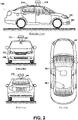
- FIG. 2 shows a vehicle 200 that could be similar or identical to vehicle 100 described in reference to Figure 1 .
- vehicle 200 includes the following sensor elements: a sensor unit 202, a wireless communication system 204, a LIDAR 206, a laser rangefinder 208, and a camera 210.
- the sensor elements of vehicle 200 in combination perhaps with other sensor elements not described, constitute part of sensor system 104, as described with respect to Figure 1 .
- vehicle 200 is illustrated in Figure 2 as a car, other embodiments are possible.
- the vehicle 200 could represent a truck, a van, a semi-trailer truck, a motorcycle, a bicycle, a golf cart, an off-road vehicle, or a farm vehicle, among other examples.
- the sensor unit 202 is configured to capture information about an environment of the vehicle 200.
- sensor unit 202 could include or communicatively couple with any combination of cameras, RADARs, LIDARs, range finders, and acoustic sensors. Other types of sensors are possible as well.
- the sensor unit 202 includes one or more movable mounts that could be operable to adjust the orientation of one or more sensors in the sensor unit 202.
- the movable mount could include a rotating platform that could scan sensors so as to obtain information from each direction around the vehicle 200.
- the movable mount of the sensor unit 202 could be moveable in a scanning fashion within a particular range of angles and/or azimuths.
- the sensor unit 202 could be mounted atop the roof of a car, for instance, however other mounting locations are possible. Additionally, the sensors of sensor unit 202 could be distributed in different locations and need not be collocated in a single location. Some possible sensor types and mounting locations include LIDAR 206 and laser rangefinder 208.
- the wireless communication system 204 could be located as depicted in Figure 2 . Alternatively, the wireless communication system 204 could be located, fully or in part, elsewhere.
- the wireless communication system 204 may include wireless transmitters and receivers that could be configured to communicate with devices external or internal to the vehicle 200.
- the wireless communication system 204 could include transceivers configured to communicate with other vehicles and/or computing devices, for instance, in a vehicular communication system or a roadway station. Examples of such vehicular communication systems include dedicated short range communications (DSRC), radio frequency identification (RFID), and other proposed communication standards directed towards intelligent transport systems.
- DSRC dedicated short range communications
- RFID radio frequency identification
- the camera 210 could be mounted inside a front windshield of the vehicle 200.
- the camera 210 could be configured to capture a plurality of images of the environment of the vehicle 200. Specifically, as illustrated, the camera 210 could capture images from a forward-looking view with respect to the vehicle 200. Other mounting locations and viewing angles of camera 210 are possible.
- the camera 210 could represent one or more visible light cameras. Alternatively or additionally, camera 210 could include infrared sensing capabilities.
- the camera 210 could have associated optics that could be operable to provide an adjustable field of view. Further, the camera 210 could be mounted to vehicle 200 with a movable mount that could be operable to vary a pointing angle of the camera 210.
- Figures 3A and 3B illustrate example scenarios in which vehicles are travelling on a roadway.
- the roadway is depicted as having two lanes, a left-hand lane and a right-hand lane, with traffic in each lane travelling the same direction.
- vehicle 308 Depicted on the roadway in Figure 3A is vehicle 308, car 316, and truck 314.
- vehicle 308 and semi-truck 330 Depicted on the roadway in Figure 3B is vehicle 308 and semi-truck 330.
- vehicle 308 could be operating in an autonomous mode and collecting sensor data via sensor unit 310 and perhaps other sensor elements.
- a camera may capture a plurality of images of the environment for analysis by a controller of the vehicle 308.
- vehicle 308 may collect a series of data points for analysis by the controller of vehicle 308. This analysis may reveal certain characteristics of each obstacle, including shape, orientation, heading, speed, distance between the given obstacle and the vehicle 308, and a distance between the given obstacle and other detected obstacles. Additional characteristics are possible as well.
- the sensor unit 310 has collected two clusters of data points: one cluster at the current position of vehicle 316 and another cluster at the current position of vehicle 314. These data points are depicted as small squares 326 and in some embodiments are collected by detecting the reflections of emitted RADAR or laser signals.
- Each cluster may be preliminarily classified by the vehicle 308 as an obstacle. However, upon an additional analysis, given the close proximity of the two obstacles and a similar speed of each obstacle, vehicle 308 may erroneously classify the two obstacles as one large obstacle 324 that spans the width of both lanes.
- the more accurate classification of the two obstacles is as two separate obstacles, 320 and 322.
- the sensor unit 310 has similarly collected two clusters of data points: one cluster located at the cab of the semi-truck 330 and another cluster located along the trailer of semi-truck 330. Again, these data points are depicted as small squares 338.
- Vehicle 308 may preliminarily classify each cluster of data points as an obstacle. However, upon an additional analysis, given the shape of the two obstacles, vehicle 308 may erroneously classify the two obstacles as two separate obstacles, 332 and 334. The more accurate classification of the two obstacles, as revealed by Figure 3B , is that they are part of one large obstacle 336.
- the erroneous classifications of (i) the two obstacles 320 and 322 as one large obstacle 324 and (ii) the one large obstacle 336 as two separate obstacles 332 and 334 may potentially confuse the pathing system of vehicle 308 as well as other control systems of vehicle 308.
- the control systems of vehicle 308 may exit the autonomous mode and transition to a manual mode or take some other action for safety's sake. Therefore, to address situations like this and perhaps other situations, vehicle 308, in accordance with the embodiments described further herein, may engage in one or more advanced obstacle evaluation techniques in an effort to more accurately classify detected obstacles.
- a vehicle such as vehicle 308, may engage in at least one obstacle evaluation technique by comparing historical data collected for least two obstacles and determining, based on the historical data, whether the two obstacles have taken some action that is inconsistent with the two obstacles being parts of one large obstacle. Examples of such actions include (but are not limited to): a lane change, a speed differential, a changing orientation, a changing heading, etc.
- vehicle 308 collects data for two obstacles and analyzes the data to determine whether the two obstacles have had a changing differential distance between them.
- two obstacles that, at one point, were located at one distance from each other, but later are located at a different distance from each other are more likely to be two separate obstacles and less likely to be parts of one large obstacle. Whereas two obstacles that have, over time, maintained a relatively constant distance between them are more likely to be parts of one large obstacle and less likely to be two separate obstacles.
- vehicle 308 determines whether two obstacles have had a changing differential distance between them by determining whether there has been between the two obstacles a change in distance that is greater than or equal to a certain threshold distance.
- One way for the vehicle 308 to carry out such a measurement is to subtract the smallest measured distance between the two obstacles from the largest measured distance between the two obstacles.
- vehicle 308 may use such a measurement, either alone or in combination with other information as a basis to conclude that the two obstacles are two separate obstacles.
- vehicle 308 may use such a measurement, either alone or in combination with other information, as a basis to conclude that the two obstacles are parts of one large obstacle.
- This threshold distance may be, for example, five feet; however, any threshold distance (or units) can be used.
- other ways of determining whether two obstacles have had between them a changing differential distance are possible as well.
- vehicle 308 collects data for two obstacles and analyzes the data to determine whether the two obstacles have had different speeds.
- two obstacles that at one time were moving at different speeds are more likely to be two separate obstacles and less likely to be parts of one large obstacle.
- two obstacles that have, over time, comparatively maintained relatively similar speeds are more likely to be parts of one large obstacle and less likely to be two separate obstacles.
- vehicle 308 determines whether two obstacles have had different speeds by determining whether the two obstacles have had a speed differential that is greater than or equal to a certain threshold speed. In cases in which there was at one time or another measured between the two obstacles a difference in speed that is greater than or equal to the threshold speed, vehicle 308 may use such a measurement, either alone or in combination with other information, as a basis to conclude that the two obstacles are two separate obstacles. And in cases in which there was at no time measured between the two obstacles a difference in speed that is greater than or equal to the threshold speed, vehicle 308 may use such a measurement, either alone or in combination with other information, as a basis to conclude that the two obstacles are parts of one large obstacle.
- This threshold speed may be, for example, five MPH; however, any threshold speed (or units) can be used. Moreover, other ways of determining whether two obstacles have had different simultaneous speeds are possible as well.
- vehicle 308 collects data for two obstacles and analyzes the data to determine whether the two obstacles have had different relative orientations or headings.
- two obstacles that at one time were facing different directions or had different relative headings are more likely to be two separate obstacles and less likely to be parts of one large obstacle.
- two obstacles that have, over time, comparatively maintained similar orientations or headings are more likely to be parts of one large obstacle and less likely to be two separate obstacles.
- vehicle 308 determines whether two obstacles have had different relative orientations or headings by determining whether the two obstacles have had a difference in orientation or heading that is greater than a certain threshold degree. In cases in which there was at one time or another measured between the two obstacles a difference in heading or orientation that is greater than or equal to the threshold degree, vehicle 308 may use such a measurement, either alone or in combination with other information, as a basis to conclude that the two obstacles are two separate obstacles. And in cases in which there was at no time measured between the two obstacles a difference in orientation or heading that is greater than or equal to the threshold degree, vehicle 308 may use such a measurement, either alone or in combination with other information, as a basis to conclude that the two obstacles are parts of one large obstacle.
- This threshold degree may be, for example, four degrees; however, any threshold degree (or units) can be used. Moreover, other ways of determining whether two obstacles have ever had different relative orientations or headings are possible as well.
- a certain threshold value in order to make the obstacle evaluation process more accurate (or for other reasons).
- Such situations may include (but are not limited to): when traffic conditions change (e.g., from congested to clear), when road conditions or weather changes (e.g., from dry to wet), when the type of roadway changes (e.g., from city to highway), when the time changes (e.g., from night to day), or for any other reason.
- traffic conditions change e.g., from congested to clear
- road conditions or weather changes e.g., from dry to wet
- the type of roadway changes e.g., from city to highway
- time changes e.g., from night to day
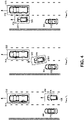
- Figure 4 depicts an example scenario in which vehicle 308 may engage in an obstacle evaluation technique, in accordance with an example embodiment.
- the scenario in Figure 4 is depicted at three times, T 1 , T2, and T3.
- vehicle 308 is traveling on a roadway in the left-hand lane, whereas car 316 and truck 314 are traveling on the roadway in the right-hand lane.
- Vehicle 308 is operating in an autonomous mode and collecting data via the sensor unit 310.
- the data is in the form of a plurality of data points, depicted in Figure 4 as small squares 326. As depicted, one cluster of data points is detected at the position of car 316 and another cluster of data points is detected at the position of truck 314.
- the vehicle 308 may preliminarily classify one cluster as obstacle 320 and the other cluster as obstacle 322. Further, based on the collected data, vehicle 308 may determine that obstacle 320 is oriented in, and therefore traveling in, the same direction as obstacle 322, as indicated by the arrows protruding from each obstacle. Moreover, vehicle 308 may determine that each obstacle 320 and 322 is traveling at about 60 miles per hour (MPH), and are about twenty feet apart.
- MPH miles per hour
- vehicle 308 may continue collecting sensor data for obstacles 320 and 322 and determine that, based on the data, obstacle 320 has increased its speed to 70 MPH and moved fifteen feet closer to obstacle 322 while at the same time changed its heading about five degrees to the left and begun to change lanes in front of vehicle 308. Further, based on the collected data, vehicle 308 may determine that obstacle 322 has maintained relatively the same heading and speed since time T 1 .
- vehicle 308 may continue collecting sensor data for obstacles 320 and 322 and determine that, based on the data, both obstacles 320 and 322 are traveling at about 60 MPH, maintaining about the same heading, and are about a few feet apart.
- vehicle 308 may engage in an obstacle evaluation technique, in accordance with at least some of the above-described procedures. For example, the vehicle 308 may analyze the history of collected data for obstacles 320 and 322 since time T 1 , and determine that the obstacles have had between them (i) a change in distance of over fifteen feet, (ii) a maximum simultaneous speed differential of about ten MPH, and (iii) and a maximum heading or orientation differential of about five degrees.
- the vehicle 308 may further determine that at least one of these measurements exceeds a corresponding threshold. Therefore, vehicle 308 may use this determination, either alone or in combination with other information, as a basis to conclude that obstacles 320 and 322 are two separate obstacles. As a result of this conclusion, vehicle 308 may continue to maintain a cache of obstacle history data for each obstacle 320 and 322, as well as take any other action in accordance with the operation of vehicle 308 when it detects two separate obstacles.
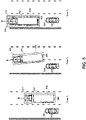
- Figure 5 depicts another example scenario in which vehicle 308 may engage in an obstacle evaluation technique, in accordance with an example embodiment.
- the scenario in Figure 5 is depicted at three times, T 1 , T2, and T3.
- vehicle 308 is traveling on a roadway in the left-hand lane, whereas semi-truck 330 is traveling on the roadway in the right-hand lane.
- Vehicle 308 is operating in an autonomous mode and collecting data points (depicted again as small squares 338) via the sensor unit 310. As depicted, one cluster of data points is detected at the position of the cab of semi-truck 330 and another cluster of data points is detected along the trailer of semi-truck 330.
- the vehicle 308 may preliminarily classify one cluster as obstacle 332 and the other cluster as obstacle 334. Further, based on the collected data, vehicle 308 may determine that each obstacle is oriented in, and therefore traveling in, the same direction, as indicated by the arrows protruding from each obstacle. Moreover, vehicle 308 may determine that each obstacle 332 and 334 is traveling at about the same speed (60 MPH), and about four feet apart.
- vehicle 308 may continue collecting sensor data for obstacles 332 and 334 and determine that, based on the data, each obstacle has increased its speed to 70 MPH and each obstacle has changed its heading about five degrees to the left and begun to change lanes in front of vehicle 308. Further, based on the collected data, vehicle 308 may determine that each obstacle has maintained between them a relatively constant distance of four feet.
- vehicle 308 may continue collecting sensor data for obstacles 320 and 322 and determine that, based on the data, both obstacles 332 and 334 have reduced their speeds to about 60 MPH, are maintaining about the same heading, and are still about four feet apart.
- vehicle 308 may engage in an obstacle evaluation technique, in accordance with at least some of the above-described procedures. For example, the vehicle 308 may analyze the history of collected data for obstacles 332 and 334 since time T 1 , and determine that the obstacles have had between them (i) a relatively constant distance differential, (ii) a near-zero MPH speed differential, and (iii) and relatively similar simultaneous headings or orientations. The vehicle 308 may further determine that none of these measurements exceeds a corresponding threshold.
- vehicle 308 may use this determination, either alone or in combination with other information, as a basis to conclude that obstacles 332 and 334 are parts of one large obstacle 336. As a result of this conclusion, vehicle 308 may merge the cache of obstacle history data for each obstacle 332 and 334, as well as take any other action in accordance with the operation of vehicle 308 when it detects one large obstacle.
- vehicle 308 may engage in an obstacle evaluation technique.
- vehicle 308 may detect three or more obstacles (e.g., obstacles A, B, and C) and engage in an obstacle evaluation technique for each obstacle pair of the detected obstacles (e.g., A-B, A-C, and B-C).
- obstacles e.g., obstacles A, B, and C
- an obstacle evaluation technique for each obstacle pair of the detected obstacles (e.g., A-B, A-C, and B-C).
- Still other examples are possible as well.
- Figure 6 is a flow diagram 600 that depicts an example obstacle evaluation process.
- the example process may include one or more operations, functions, or actions, as depicted by one or more of blocks 602, 604, 606, 608, and/or 610, each of which may be carried out by any of the systems described by way of Figures 1-5 ; however, other configurations could be used.
- each block of each flow diagram may represent a module, a segment, or a portion of program code, which includes one or more instructions executable by a processor (e.g., processor 113 in computer system 112 described above with respect to vehicle 100) for implementing specific logical functions or steps in the process.
- the program code may be stored on any type of computer readable medium (e.g., computer readable storage medium or non-transitory media, such as data storage 114 described above with respect to vehicle 100), for example, such as a storage device including a disk or hard drive.
- each block may represent circuitry that is wired to perform the specific logical functions in the process.
- Alternative implementations are included within the scope of the example embodiments of the present application in which functions may be executed out of order from that shown or discussed, including substantially concurrent or in reverse order, depending on the functionality involved, as would be understood by those reasonably skilled in the art.
- the flow diagram 600 begins at block 602 where a vehicle collects data for a plurality of obstacles.
- a vehicle collects data for a plurality of obstacles.
- at least one sensor element such as a camera, RADAR, laser rangefinder / LIDAR, or other element may collect a series of data points for each obstacle. These data points may reveal various characteristics about each obstacle at the time in which the data was collected, including for example, the shape, orientation, heading, and speed of the obstacle, as well as distances between the obstacle and other obstacle or the vehicle itself. Other ways of collecting such data exists as well.
- the vehicle engages in an evaluation process for two obstacles of the plurality of obstacles.
- one way for a vehicle to engage in an evaluation process is to compare the data collected for the two obstacles and determine the extent to which the obstacles have changed their distance from one another, changed their speed relative to one another, and changed their orientation or heading relative to one another.
- Other ways to engage in an evaluation process are possible as well.
- the vehicle makes a determination of whether, based on the evaluation process, at least one threshold condition is met. For instance, in some embodiments, the vehicle may determine whether the obstacles have had between them a change in distance that is greater than or equal to a certain distance threshold. In some embodiments, the vehicle may determine whether the obstacles have had between them a differential speed that is greater than or equal to a certain speed threshold. And in some embodiments, the vehicle may determine whether the obstacles have had between them an orientation differential that is greater than or equal to an orientation threshold. The vehicle may engage in any number of other threshold-condition determinations as well.
- the vehicle may use such a determination, either alone or in combination with other information, as a basis to proceed to block 608 and classify the two obstacles as two separate obstacles. If, however, the vehicle determines that no threshold conditions are met, the vehicle may use such a determination, either alone or in combination with other information, as a basis to proceed to block 610 and classify the two obstacles as one large obstacle. Other responsive actions are possible as well.
- Example processes such as the one depicted by flow diagram 600, as well as other example processes described herein, may be carried out in whole or in part by the vehicle and its subsystems. However, it should be understood that an example process may be implemented in whole or in part by other computing devices, such as those located remotely from the vehicle. For example, an example process may be implemented in whole or in part by a server system, which receives data from a device such as those associated with the vehicle. Other examples of computing devices or combinations of computing devices that can implement an example process are possible.
- processes described herein may be implemented as computer program instructions encoded on a non-transitory computer-readable storage media in a machine-readable format, or on other non-transitory media or articles of manufacture.
- Figure 7 is a schematic illustrating a conceptual partial view of an example computer program product that includes a computer program for executing a computer process on a computing device, arranged according to at least some embodiments presented herein.
- the example computer program product 700 is provided using a signal bearing medium 702.
- the signal bearing medium 702 may include one or more programming instructions 704 that, when executed by one or more processors may provide functionality or portions of the functionality described above with respect to Figures 1-6 .
- the signal bearing medium 702 may encompass a computer-readable medium 706, such as, but not limited to, a hard disk drive, a Compact Disc (CD), a Digital Video Disk (DVD), a digital tape, memory, etc.
- the signal bearing medium 702 may encompass a computer recordable medium 708, such as, but not limited to, memory, read/write (R/W) CDs, R/W DVDs, etc.
- the signal bearing medium 702 may encompass a communications medium 710, such as, but not limited to, a digital and/or an analog communication medium (e.g., a fiber optic cable, a waveguide, a wired communications link, a wireless communication link, etc.).
- a communications medium 710 such as, but not limited to, a digital and/or an analog communication medium (e.g., a fiber optic cable, a waveguide, a wired communications link, a wireless communication link, etc.).
- the signal bearing medium 702 may be conveyed by a wireless form of the communications medium 710.
- the one or more programming instructions 704 may be, for example, computer executable and/or logic implemented instructions.
- a computing device such as the computer system 112 of Figure 1 may be configured to provide various operations, functions, or actions in response to the programming instructions 704 conveyed to the processor 113 by one or more of the computer readable medium 706, the computer recordable medium 708, and/or the communications medium 710 (e.g., instructions 115 stored in data storage 114).
- the non-transitory computer readable medium could also be distributed among multiple data storage elements, which could be remotely located from each other.
- the computing device that executes some or all of the stored instructions could be a vehicle, such as the vehicle 200 illustrated in Figure 2 .
- the computing device that executes some or all of the stored instructions could be another computing device, such as a server.
Landscapes
- Engineering & Computer Science (AREA)
- Mechanical Engineering (AREA)
- Physics & Mathematics (AREA)
- Automation & Control Theory (AREA)
- Transportation (AREA)
- General Physics & Mathematics (AREA)
- Multimedia (AREA)
- Theoretical Computer Science (AREA)
- Mathematical Physics (AREA)
- Traffic Control Systems (AREA)
- Control Of Driving Devices And Active Controlling Of Vehicle (AREA)
- Radar Systems Or Details Thereof (AREA)
- Optical Radar Systems And Details Thereof (AREA)
Abstract
Description
- Unless otherwise indicated herein, the materials described in this section are not prior art to the claims in this application and are not admitted to be prior art by inclusion in this section.
- Generally, a vehicle is a powered, movable machine. Examples of vehicles include cars, trucks, motorcycles, buses, bicycles, etc. Vehicles can be utilized for various tasks such as transportation of people and cargo, as well as many other uses.
- Some vehicles may be partially or fully automated. For instance, when a vehicle is in an automated mode, some or all of the driving aspects of vehicle operation can be handled by a vehicle control system. In such cases, computing devices located on-board and/or in a server network could be operable to carry out functions such as planning a driving route, sensing aspects of the vehicle, sensing the environment of the vehicle, and controlling drive components such as steering, throttle, and brake. Thus, autonomous vehicles may reduce the need for human interaction in various aspects of vehicle operation.
- In operation, an autonomous vehicle sensor system may analyze the environment of the vehicle and detect the presence of certain obstacles, such as other cars. Based on the positions or other characteristics of the detected obstacles, the vehicle may classify some obstacles as just parts of one large obstacle, and other obstacles as separate and distinct obstacles. However, in some situations, these classifications may be erroneous. For example, when two cars are positioned side-by-side or when a motorcycle is passing a semi-truck, a vehicle system may erroneously classify each of these obstacle pairs as just one large obstacle as a result of their close proximity.
- Therefore, to address situations like this, and perhaps other situations, disclosed herein are methods and systems in which a vehicle engages in an advanced obstacle evaluation technique. More particularly, a vehicle may collect a history of data for at least two obstacles. Such data may be related to the speed, distance, orientation, or some other characteristic of each obstacle. The vehicle may then compare this historical data and determine whether one the two obstacles has taken some action that is inconsistent with the two obstacles being parts of one large obstacle (e.g., a lane change). Depending on the result of the comparison, the vehicle may classify the two obstacles as one large obstacle or two separate obstacles, as the case may be. Other examples of obstacle evaluation techniques are possible as well.
- For example, in accordance with one embodiment, a method is provided and includes a vehicle system employing at least one sensor to collect data relating to a plurality of obstacles, identifying from the plurality of obstacles an obstacle pair including a first obstacle and a second obstacle, engaging in an evaluation process by comparing the data collected for the first obstacle to the data collected for the second obstacle, and based on the evaluation process, making a determination of whether the first obstacle and the second obstacle are two separate obstacles.
- In accordance with another embodiment, another method is provided and includes a vehicle system using a sensor system to collect data for a first obstacle and a second obstacle including at least one of speed data, distance data, and orientation data, engaging in a first evaluation process by comparing the collected data and determining whether a first threshold is met, based on the first evaluation process, the vehicle system making a first determination of whether the first obstacle and the second obstacle are two separate obstacles, detecting that one or more environmental conditions have changed and responsively changing the first threshold to a second threshold, engaging in a second evaluation process by comparing the collected data and determining whether the second threshold is met, and based on the second evaluation process, making a second determination of whether the first obstacle and the second obstacle are two separate obstacles.
- In accordance with another embodiment, a vehicle is provided and includes at least one sensor, at least one processor, and data storage comprising instructions executable by the at least one processor to receive from the at least one sensor data relating to a plurality of potential obstacles, conduct at least one evaluation on a pair of potential obstacles in the plurality of potential obstacles including a threshold comparison of the received data, classify the pair of potential obstacles as a single obstacle when the evaluation indicates that no threshold comparison of the received data is met, and classify the pair of potential obstacles as two separate obstacles when the evaluation indicates that at least one threshold comparison of the received data is met.
- In accordance with another embodiment, a non-transitory computer readable medium (CRM) is disclosed. This CRM has stored thereon instructions executable by a computing device to cause the computing device to perform functions, which may include employing at least one sensor to collect data relating to a plurality of obstacles, identifying from the plurality of obstacles an obstacle pair including a first obstacle and a second obstacle, engaging in an evaluation process by comparing the data collected for the first obstacle to the data collected for the second obstacle, and based on the evaluation process, making a determination of whether the first obstacle and the second obstacle are two separate obstacles.
- The foregoing summary is illustrative and is not intended to be in any way limiting. In addition to these illustrative aspects, embodiments, and features described above, further aspects, embodiments, and features will become apparent by reference to the figures and the following detailed description.
-
-
Figure 1 is a block diagram depicting a vehicle, according to an example embodiment. -
Figure 2 depicts a vehicle, according to an example embodiment. -
Figure 3A is a vehicle-operating scenario, according to an example embodiment. -
Figure 3B is a vehicle-operating scenario, according to an example embodiment. -
Figure 4 is a vehicle-operating scenario, according to an example embodiment. -
Figure 5 is a vehicle-operating scenario, according to an example embodiment. -
Figure 6 depicts a flow diagram, according to an example embodiment. -
Figure 7 is a schematic diagram of a computer program product, according to an example embodiment. - Example methods and systems are described herein. Any example embodiment or feature described herein is not necessarily to be construed as preferred or advantageous over other embodiments or features. The example embodiments described herein are not meant to be limiting. It will be readily understood that certain aspects of the disclosed systems and methods can be arranged and combined in a wide variety of different configurations, all of which are contemplated herein.
- Furthermore, the particular arrangements shown in the Figures should not be viewed as limiting. It should be understood that other embodiments may include more or less of each element shown in a given Figure. Further, some of the illustrated elements may be combined or omitted. Yet further, an example embodiment may include elements that are not illustrated in the Figures.
- Example embodiments disclosed herein relate to operating a vehicle in an autonomous mode; and in particular, engaging in at least one obstacle evaluation technique in order to determine whether two obstacles are two separate obstacles (e.g., two cars), or whether they are parts of one large obstacle (e.g., two parts of a large truck).
- Within the context of the disclosure, the vehicle could be operable in various modes of operation. In at least one embodiment, such modes of operation include manual, semi-autonomous, and autonomous modes. In particular, the autonomous mode may provide driving operation with little or no user interaction. Manual and semi-autonomous modes of operation could include greater degrees of user interaction.
- Some methods disclosed herein could be carried out in part or in full by a vehicle configured to operate in an autonomous mode with or without external interaction (e.g., such as from a user of the vehicle). Other methods disclosed herein could be carried out in part or in full by a server. Those skilled in the art will understand that there are many different specific methods and systems that could be used during the operation of a vehicle. Each of these specific methods and systems are contemplated herein, and several example embodiments are described below.
-
Figure 1 is a functional block diagram illustrating avehicle 100, according to an example embodiment. Thevehicle 100 could be configured to operate fully or partially in an autonomous mode. For example, thevehicle 100 could control itself while in the autonomous mode, and may be operable to engage in an evaluation process (among other processes), in accordance with the description set forth herein. While in autonomous mode, thevehicle 100 may operate without human interaction. - The
vehicle 100 could include various subsystems such as apropulsion system 102, asensor system 104, acontrol system 106, one or more peripherals 108, as well as apower supply 110, acomputer system 112, and auser interface 116. Thevehicle 100 may include more or fewer subsystems and each subsystem could include multiple elements. Further, each of the subsystems and elements ofvehicle 100 could be interconnected. Thus, one or more of the described functions of thevehicle 100 may be divided up into additional functional or physical components, or combined into fewer functional or physical components. In some further examples, additional functional and/or physical components may be added to the examples illustrated byFigure 1 . - The
propulsion system 102 may include components operable to provide powered motion for thevehicle 100. Depending upon the embodiment, thepropulsion system 102 could include an engine/motor 118, anenergy source 119, atransmission 120, and wheels/tires 121. The engine/motor 118 could be any combination of an internal combustion engine, an electric motor, steam engine, Stirling engine, or other types of engines and/or motors. In some embodiments, the engine/motor 118 may be configured to convertenergy source 119 into mechanical energy. In some embodiments, thepropulsion system 102 could include multiple types of engines and/or motors. For instance, a gas-electric hybrid car could include a gasoline engine and an electric motor. Other examples are possible. - The
energy source 119 could represent a source of energy that may, in full or in part, power the engine/motor 118. That is, the engine/motor 118 could be configured to convert theenergy source 119 into mechanical energy. Examples ofenergy sources 119 include gasoline, diesel, other petroleum-based fuels, propane, other compressed gas-based fuels, ethanol, solar panels, batteries, and other sources of electrical power. The energy source(s) 119 could additionally or alternatively include any combination of fuel tanks, batteries, capacitors, and/or flywheels. Theenergy source 119 could also provide energy for other systems of thevehicle 100. - The
transmission 120 could include elements that are operable to transmit mechanical power from the engine/motor 118 to the wheels/tires 121. To this end, thetransmission 120 could include a gearbox, clutch, differential, and drive shafts. Thetransmission 120 could include other elements as well. The drive shafts could include one or more axles that could be coupled to the one or more wheels/tires 121. - The wheels/
tires 121 ofvehicle 100 could be configured in various formats, including a unicycle, bicycle/motorcycle, tricycle, or car/truck four-wheel format. Other wheel/tire geometries are possible, such as those including six or more wheels. Any combination of the wheels/tires 121 ofvehicle 100 may be operable to rotate differentially with respect to other wheels/tires 121. The wheels/tires 121 could represent at least one wheel that is fixedly attached to thetransmission 120 and at least one tire coupled to a rim of the wheel that could make contact with the driving surface. The wheels/tires 121 could include any combination of metal and rubber, or another combination of materials. In other embodiments, other locomotion schemes are possible either in combination with wheels/tires 121 or in substitution thereof, including, for example, tracks, treads, skis, or others. - The
sensor system 104 may include a number of sensors configured to sense information about an environment of thevehicle 100. For example, thesensor system 104 could include a Global Positioning System (GPS) 122, an inertial measurement unit (IMU) 124, aRADAR unit 126, a laser rangefinder /LIDAR unit 128, and acamera 130. Thesensor system 104 could also include sensors configured to monitor internal systems of the vehicle 100 (e.g., O2 monitor, fuel gauge, engine oil temperature). Other sensors are possible as well. - One or more of the sensors included in
sensor system 104 could be configured to be actuated separately and/or collectively in order to modify a position and/or an orientation of the one or more sensors. - The
GPS 122 may be any sensor configured to estimate a geographic location of thevehicle 100. To this end,GPS 122 could include a transceiver operable to provide information regarding the position of thevehicle 100 with respect to the Earth. - The
IMU 124 could include any combination of sensors (e.g., accelerometers and gyroscopes) configured to sense position and orientation changes of thevehicle 100 based on inertial acceleration. - The
RADAR unit 126 may represent a system that utilizes radio signals to sense objects within the local environment of thevehicle 100. In some embodiments, in addition to sensing the objects, theRADAR unit 126 may additionally be configured to sense the speed and/or heading of the objects. - Similarly, the laser rangefinder or
LIDAR unit 128 may be any sensor configured to sense objects in the environment in which thevehicle 100 is located using lasers. Depending upon the embodiment, the laser rangefinder /LIDAR unit 128 could include one or more laser sources, a laser scanner, and one or more detectors, among other system components. The laser rangefinder /LIDAR unit 128 could be configured to operate in a coherent (e.g., using heterodyne detection) or an incoherent detection mode. Thecamera 130 could include one or more devices configured to capture a plurality of images of the environment of thevehicle 100. Thecamera 130 could be a still camera or a video camera. - The
control system 106 may be configured to control operation of thevehicle 100 and its components. Accordingly, thecontrol system 106 could include various elements, such assteering unit 132,throttle 134,brake unit 136, asensor fusion algorithm 138, acomputer vision system 140, a navigation /pathing system 142, and anobstacle avoidance system 144. Thesteering unit 132 could represent any combination of mechanisms that may be operable to adjust the heading ofvehicle 100. - The
throttle 134 could be configured to control, for instance, the operating speed of the engine/motor 118 and, in turn, control the speed of thevehicle 100. - The
brake unit 136 could include any combination of mechanisms configured to decelerate thevehicle 100. Thebrake unit 136 could use friction to slow the wheels/tires 121. In other embodiments, thebrake unit 136 could convert the kinetic energy of the wheels/tires 121 to electric current. Thebrake unit 136 may take other forms as well. - The
sensor fusion algorithm 138 may be an algorithm (or a computer program product storing an algorithm) configured to accept data from thesensor system 104 as an input. The data may include, for example, data representing information sensed at the sensors of thesensor system 104. Thesensor fusion algorithm 138 could include, for instance, a Kalman filter, Bayesian network, or other algorithm. Thesensor fusion algorithm 138 could further provide various assessments based on the data fromsensor system 104. Depending upon the embodiment, the assessments could include evaluations of individual objects and/or features in the environment ofvehicle 100, evaluation of a particular situation, and/or evaluate possible impacts based on the particular situation. Other assessments are possible. - The
computer vision system 140 may be any system operable to process and analyze images captured bycamera 130 in order to identify objects and/or features in the environment ofvehicle 100 that could include traffic signals, road way boundaries, and obstacles. Thecomputer vision system 140 could use an object recognition algorithm, a Structure From Motion (SFM) algorithm, video tracking, and other computer vision techniques. In some embodiments, thecomputer vision system 140 could be additionally configured, perhaps in combination with elements of other vehicle systems, to map an environment, track objects, estimate obstacle speeds, estimate distances between various obstacles and between an obstacle andvehicle 100, estimate heading and/or orientation of an obstacle (i.e., the direction in which an obstacle is facing or traveling, measured, for example, on a 360 degree scale), or other characteristics of obstacles. - The navigation and
pathing system 142 may be any system configured to determine a driving path for thevehicle 100. The navigation andpathing system 142 may additionally be configured to update the driving path dynamically while thevehicle 100 is in operation. In some embodiments, the navigation andpathing system 142 could be configured to incorporate data from thesensor fusion algorithm 138, theGPS 122, and one or more predetermined maps so as to determine the driving path forvehicle 100. - The
obstacle avoidance system 144 could represent a control system configured to identify, evaluate , and avoid or otherwise negotiate potential obstacles in the environment of thevehicle 100. - The
control system 106 may additionally or alternatively include components other than those shown and described.Peripherals 108 may be configured to allow interaction between thevehicle 100 and external sensors, other vehicles, other computer systems, and/or a user. For example,peripherals 108 could include awireless communication system 146, atouchscreen 148, amicrophone 150, and/or aspeaker 152. - In an example embodiment, the
peripherals 108 could provide, for instance, means for a user of thevehicle 100 to interact with theuser interface 116. To this end, thetouchscreen 148 could provide information to a user ofvehicle 100. Theuser interface 116 could also be operable to accept input from the user via thetouchscreen 148. Thetouchscreen 148 may be configured to sense at least one of a position and a movement of a user's finger via capacitive sensing, resistance sensing, or a surface acoustic wave process, among other possibilities. Thetouchscreen 148 may be capable of sensing finger movement in a direction parallel or planar to the touchscreen surface, in a direction normal to the touchscreen surface, or both, and may also be capable of sensing a level of pressure applied to the touchscreen surface. Thetouchscreen 148 may be formed of one or more translucent or transparent insulating layers and one or more translucent or transparent conducting layers. Thetouchscreen 148 may take other forms as well. - In other instances, the
peripherals 108 may provide means for thevehicle 100 to communicate with devices within its environment. Themicrophone 150 may be configured to receive audio (e.g., a voice command or other audio input) from a user of thevehicle 100. Similarly, thespeakers 152 may be configured to output audio to the user of thevehicle 100. - In one example, the
wireless communication system 146 could be configured to wirelessly communicate with one or more devices directly or via a communication network. For example,wireless communication system 146 could use 3G cellular communication, such as CDMA, EVDO, GSM/GPRS, or 4G cellular communication, such as WiMAX or LTE. Alternatively,wireless communication system 146 could communicate with a wireless local area network (WLAN), for example, using WiFi. In some embodiments,wireless communication system 146 could communicate directly with a device, for example, using an infrared link, Bluetooth, or ZigBee. Other wireless protocols, such as various vehicular communication systems, are possible within the context of the disclosure. For example, thewireless communication system 146 could include one or more dedicated short range communications (DSRC) devices that could include public and/or private data communications between vehicles and/or roadside stations. - The
power supply 110 may provide power to various components ofvehicle 100 and could represent, for example, a rechargeable lithium-ion, lead-acid battery, or even a fixed power supply, such as a 120 Volt Alternating Current power supply. In some embodiments, one or more banks of such batteries could be configured to provide electrical power. Other power supply materials and configurations are possible. In some embodiments, thepower supply 110 andenergy source 119 could be implemented together, as in some all-electric cars. - Many or all of the functions of
vehicle 100 could be controlled bycomputer system 112.Computer system 112 may include at least one processor 113 (which could include at least one microprocessor) that executesinstructions 115 stored in a non-transitory computer readable medium, such as thedata storage 114. Thecomputer system 112 may also represent a plurality of computing devices that may serve to control individual components or subsystems of thevehicle 100 in a distributed fashion. - In some embodiments,
data storage 114 may contain instructions 115 (e.g., program logic) executable by theprocessor 113 to execute various functions ofvehicle 100, including those described above in connection withFigure 1 .Data storage 114 may contain additional instructions as well, including instructions to transmit data to, receive data from, interact with, and/or control one or more of thepropulsion system 102, thesensor system 104, thecontrol system 106, and theperipherals 108. - In addition to the
instructions 115, thedata storage 114 may store data such as roadway maps, path information, among other information. Such information may be used byvehicle 100 andcomputer system 112 at during the operation of thevehicle 100 in the autonomous, semi-autonomous, and/or manual modes. - The
vehicle 100 may include auser interface 116 for providing information to or receiving input from a user ofvehicle 100. Theuser interface 116 could control or enable control of content and/or the layout of interactive images that could be displayed on thetouchscreen 148. Further, theuser interface 116 could include one or more input/output devices within the set ofperipherals 108, such as thewireless communication system 146, thetouchscreen 148, themicrophone 150, and thespeaker 152. - The
computer system 112 may control the function of thevehicle 100 based on inputs received from various subsystems (e.g.,propulsion system 102,sensor system 104, and control system 106), as well as from theuser interface 116. For example, thecomputer system 112 may utilize input from thecontrol system 106 in order to control thesteering unit 132 to avoid an obstacle detected by thesensor system 104 and theobstacle avoidance system 144. Depending upon the embodiment, thecomputer system 112 could be operable to provide control over many aspects of thevehicle 100 and its subsystems. - The components of
vehicle 100 could be configured to work in an interconnected fashion with other components within or outside their respective systems. For instance, in an example embodiment, thecamera 130 could capture a plurality of images that could represent information about a state of an environment of thevehicle 100 operating in an autonomous mode. The environment could include, among other things, another vehicle. Thecomputer vision system 140 could recognize the other vehicle as such based on object recognition models stored indata storage 114, or other techniques. - The
computer system 112 could carry out several determinations based this information about the state of the environment ofvehicle 100. For example, thecomputer system 112 could determine one or more predicted behaviors of the other vehicle. The predicted behavior could be based on several factors including the current state of the vehicle 100 (e.g., vehicle speed, current lane, etc.) and the current state of the environment of the vehicle 100 (e.g., speed limit, number of available lanes, position and relative motion of other vehicles, etc.). - In some embodiments, the
computer system 112 interfaces withdata storage 114 and other systems in order to control thecontrol system 106 based on at least on the predicted behavior, the current state of thevehicle 100, and the current state of the environment of thevehicle 100. For example, in one situation, thecomputer system 112 may elect to adjust nothing as the likelihood of the other vehicle staying in its own lane is high. In another situation, however, thecomputer system 112 may elect to controlvehicle 100 to slow down slightly (by reducing throttle 134) or to shift slightly to one direction or another (by controlling steering unit 132) within the current lane in order to avoid a potential collision. Other examples of interconnection between the components ofvehicle 100 are numerous and possible within the context of the disclosure. - Although
Figure 1 shows various components ofvehicle 100, i.e.,wireless communication system 146,computer system 112,data storage 114, anduser interface 116, as being integrated into thevehicle 100, one or more of these components could be mounted or associated separately from thevehicle 100. For example,data storage 114 could, in part or in full, exist separate from thevehicle 100. Thus, thevehicle 100 could be provided in the form of device elements that may be located separately or together. The device elements that make upvehicle 100 could be communicatively coupled together in a wired and/or wireless fashion. -
Figure 2 shows avehicle 200 that could be similar or identical tovehicle 100 described in reference toFigure 1 . In at least one embodiment,vehicle 200 includes the following sensor elements: asensor unit 202, awireless communication system 204, aLIDAR 206, alaser rangefinder 208, and acamera 210. In some embodiments, the sensor elements ofvehicle 200, in combination perhaps with other sensor elements not described, constitute part ofsensor system 104, as described with respect toFigure 1 . Althoughvehicle 200 is illustrated inFigure 2 as a car, other embodiments are possible. For instance, thevehicle 200 could represent a truck, a van, a semi-trailer truck, a motorcycle, a bicycle, a golf cart, an off-road vehicle, or a farm vehicle, among other examples. - In at least one embodiment, the
sensor unit 202, perhaps in conjunction with other sensor elements, is configured to capture information about an environment of thevehicle 200. For example,sensor unit 202 could include or communicatively couple with any combination of cameras, RADARs, LIDARs, range finders, and acoustic sensors. Other types of sensors are possible as well. In some embodiments, thesensor unit 202 includes one or more movable mounts that could be operable to adjust the orientation of one or more sensors in thesensor unit 202. In one embodiment, the movable mount could include a rotating platform that could scan sensors so as to obtain information from each direction around thevehicle 200. In another embodiment, the movable mount of thesensor unit 202 could be moveable in a scanning fashion within a particular range of angles and/or azimuths. Thesensor unit 202 could be mounted atop the roof of a car, for instance, however other mounting locations are possible. Additionally, the sensors ofsensor unit 202 could be distributed in different locations and need not be collocated in a single location. Some possible sensor types and mounting locations includeLIDAR 206 andlaser rangefinder 208. - The
wireless communication system 204 could be located as depicted inFigure 2 . Alternatively, thewireless communication system 204 could be located, fully or in part, elsewhere. Thewireless communication system 204 may include wireless transmitters and receivers that could be configured to communicate with devices external or internal to thevehicle 200. Specifically, thewireless communication system 204 could include transceivers configured to communicate with other vehicles and/or computing devices, for instance, in a vehicular communication system or a roadway station. Examples of such vehicular communication systems include dedicated short range communications (DSRC), radio frequency identification (RFID), and other proposed communication standards directed towards intelligent transport systems. - The
camera 210 could be mounted inside a front windshield of thevehicle 200. Thecamera 210 could be configured to capture a plurality of images of the environment of thevehicle 200. Specifically, as illustrated, thecamera 210 could capture images from a forward-looking view with respect to thevehicle 200. Other mounting locations and viewing angles ofcamera 210 are possible. Thecamera 210 could represent one or more visible light cameras. Alternatively or additionally,camera 210 could include infrared sensing capabilities. Thecamera 210 could have associated optics that could be operable to provide an adjustable field of view. Further, thecamera 210 could be mounted tovehicle 200 with a movable mount that could be operable to vary a pointing angle of thecamera 210. -
Figures 3A and 3B illustrate example scenarios in which vehicles are travelling on a roadway. In each scenario, the roadway is depicted as having two lanes, a left-hand lane and a right-hand lane, with traffic in each lane travelling the same direction. Depicted on the roadway inFigure 3A isvehicle 308,car 316, andtruck 314. And depicted on the roadway inFigure 3B isvehicle 308 and semi-truck 330. In each scenario,vehicle 308 could be operating in an autonomous mode and collecting sensor data viasensor unit 310 and perhaps other sensor elements. In particular, a camera may capture a plurality of images of the environment for analysis by a controller of thevehicle 308. Alternatively or additionally, another sensor, such as a RADAR unit or a laser rangefinder / LIDAR unit may emit a series of signals and subsequently detect a series of signal reflections. In any case, based on the operation ofsensor unit 310,vehicle 308 may collect a series of data points for analysis by the controller ofvehicle 308. This analysis may reveal certain characteristics of each obstacle, including shape, orientation, heading, speed, distance between the given obstacle and thevehicle 308, and a distance between the given obstacle and other detected obstacles. Additional characteristics are possible as well. - For example, in the example scenario depicted in
Figure 3A , thesensor unit 310 has collected two clusters of data points: one cluster at the current position ofvehicle 316 and another cluster at the current position ofvehicle 314. These data points are depicted assmall squares 326 and in some embodiments are collected by detecting the reflections of emitted RADAR or laser signals. Each cluster may be preliminarily classified by thevehicle 308 as an obstacle. However, upon an additional analysis, given the close proximity of the two obstacles and a similar speed of each obstacle,vehicle 308 may erroneously classify the two obstacles as onelarge obstacle 324 that spans the width of both lanes. The more accurate classification of the two obstacles, as revealed byFigure 3A , is as two separate obstacles, 320 and 322. - Referring now to
Figure 3B , thesensor unit 310 has similarly collected two clusters of data points: one cluster located at the cab of the semi-truck 330 and another cluster located along the trailer ofsemi-truck 330. Again, these data points are depicted assmall squares 338.Vehicle 308 may preliminarily classify each cluster of data points as an obstacle. However, upon an additional analysis, given the shape of the two obstacles,vehicle 308 may erroneously classify the two obstacles as two separate obstacles, 332 and 334. The more accurate classification of the two obstacles, as revealed byFigure 3B , is that they are part of onelarge obstacle 336. - In either scenario, the erroneous classifications of (i) the two
obstacles large obstacle 324 and (ii) the onelarge obstacle 336 as twoseparate obstacles vehicle 308 as well as other control systems ofvehicle 308. As a result of this confusion, the control systems ofvehicle 308 may exit the autonomous mode and transition to a manual mode or take some other action for safety's sake. Therefore, to address situations like this and perhaps other situations,vehicle 308, in accordance with the embodiments described further herein, may engage in one or more advanced obstacle evaluation techniques in an effort to more accurately classify detected obstacles. - Generally, a vehicle, such as
vehicle 308, may engage in at least one obstacle evaluation technique by comparing historical data collected for least two obstacles and determining, based on the historical data, whether the two obstacles have taken some action that is inconsistent with the two obstacles being parts of one large obstacle. Examples of such actions include (but are not limited to): a lane change, a speed differential, a changing orientation, a changing heading, etc. In accordance with one example evaluation technique,vehicle 308 collects data for two obstacles and analyzes the data to determine whether the two obstacles have had a changing differential distance between them. Typically, two obstacles that, at one point, were located at one distance from each other, but later are located at a different distance from each other are more likely to be two separate obstacles and less likely to be parts of one large obstacle. Whereas two obstacles that have, over time, maintained a relatively constant distance between them are more likely to be parts of one large obstacle and less likely to be two separate obstacles. - In at least one embodiment,
vehicle 308 determines whether two obstacles have had a changing differential distance between them by determining whether there has been between the two obstacles a change in distance that is greater than or equal to a certain threshold distance. One way for thevehicle 308 to carry out such a measurement is to subtract the smallest measured distance between the two obstacles from the largest measured distance between the two obstacles. In cases in which the result is greater than or equal to the threshold distance,vehicle 308 may use such a measurement, either alone or in combination with other information as a basis to conclude that the two obstacles are two separate obstacles. And in cases in which the result is smaller than the threshold distance,vehicle 308 may use such a measurement, either alone or in combination with other information, as a basis to conclude that the two obstacles are parts of one large obstacle. This threshold distance may be, for example, five feet; however, any threshold distance (or units) can be used. Moreover, other ways of determining whether two obstacles have had between them a changing differential distance are possible as well. - In accordance with another example evaluation technique,
vehicle 308 collects data for two obstacles and analyzes the data to determine whether the two obstacles have had different speeds. Typically, two obstacles that at one time were moving at different speeds are more likely to be two separate obstacles and less likely to be parts of one large obstacle. Whereas two obstacles that have, over time, comparatively maintained relatively similar speeds are more likely to be parts of one large obstacle and less likely to be two separate obstacles. - In at least one embodiment,
vehicle 308 determines whether two obstacles have had different speeds by determining whether the two obstacles have had a speed differential that is greater than or equal to a certain threshold speed. In cases in which there was at one time or another measured between the two obstacles a difference in speed that is greater than or equal to the threshold speed,vehicle 308 may use such a measurement, either alone or in combination with other information, as a basis to conclude that the two obstacles are two separate obstacles. And in cases in which there was at no time measured between the two obstacles a difference in speed that is greater than or equal to the threshold speed,vehicle 308 may use such a measurement, either alone or in combination with other information, as a basis to conclude that the two obstacles are parts of one large obstacle. This threshold speed may be, for example, five MPH; however, any threshold speed (or units) can be used. Moreover, other ways of determining whether two obstacles have had different simultaneous speeds are possible as well. - In accordance with another example evaluation technique,
vehicle 308 collects data for two obstacles and analyzes the data to determine whether the two obstacles have had different relative orientations or headings. Typically, two obstacles that at one time were facing different directions or had different relative headings are more likely to be two separate obstacles and less likely to be parts of one large obstacle. Whereas two obstacles that have, over time, comparatively maintained similar orientations or headings are more likely to be parts of one large obstacle and less likely to be two separate obstacles. - In at least one embodiment,
vehicle 308 determines whether two obstacles have had different relative orientations or headings by determining whether the two obstacles have had a difference in orientation or heading that is greater than a certain threshold degree. In cases in which there was at one time or another measured between the two obstacles a difference in heading or orientation that is greater than or equal to the threshold degree,vehicle 308 may use such a measurement, either alone or in combination with other information, as a basis to conclude that the two obstacles are two separate obstacles. And in cases in which there was at no time measured between the two obstacles a difference in orientation or heading that is greater than or equal to the threshold degree,vehicle 308 may use such a measurement, either alone or in combination with other information, as a basis to conclude that the two obstacles are parts of one large obstacle. This threshold degree may be, for example, four degrees; however, any threshold degree (or units) can be used. Moreover, other ways of determining whether two obstacles have ever had different relative orientations or headings are possible as well. - In some embodiments, there may be situations in which it is advantageous for the
vehicle 308 to change (i.e., increase or decrease) a certain threshold value in order to make the obstacle evaluation process more accurate (or for other reasons). Such situations may include (but are not limited to): when traffic conditions change (e.g., from congested to clear), when road conditions or weather changes (e.g., from dry to wet), when the type of roadway changes (e.g., from city to highway), when the time changes (e.g., from night to day), or for any other reason. A change in conditions such as these may be referred to as a change in "environmental conditions." -
Figure 4 depicts an example scenario in whichvehicle 308 may engage in an obstacle evaluation technique, in accordance with an example embodiment. The scenario inFigure 4 is depicted at three times, T1, T2, and T3. At time T1,vehicle 308 is traveling on a roadway in the left-hand lane, whereascar 316 andtruck 314 are traveling on the roadway in the right-hand lane.Vehicle 308 is operating in an autonomous mode and collecting data via thesensor unit 310. In some embodiments (as explained above) the data is in the form of a plurality of data points, depicted inFigure 4 assmall squares 326. As depicted, one cluster of data points is detected at the position ofcar 316 and another cluster of data points is detected at the position oftruck 314. At time T1, thevehicle 308 may preliminarily classify one cluster asobstacle 320 and the other cluster asobstacle 322. Further, based on the collected data,vehicle 308 may determine thatobstacle 320 is oriented in, and therefore traveling in, the same direction asobstacle 322, as indicated by the arrows protruding from each obstacle. Moreover,vehicle 308 may determine that eachobstacle - At time T2,
vehicle 308 may continue collecting sensor data forobstacles obstacle 320 has increased its speed to 70 MPH and moved fifteen feet closer toobstacle 322 while at the same time changed its heading about five degrees to the left and begun to change lanes in front ofvehicle 308. Further, based on the collected data,vehicle 308 may determine thatobstacle 322 has maintained relatively the same heading and speed since time T1. - Finally, at time T3,
vehicle 308 may continue collecting sensor data forobstacles obstacles vehicle 308 may engage in an obstacle evaluation technique, in accordance with at least some of the above-described procedures. For example, thevehicle 308 may analyze the history of collected data forobstacles vehicle 308 may further determine that at least one of these measurements exceeds a corresponding threshold. Therefore,vehicle 308 may use this determination, either alone or in combination with other information, as a basis to conclude thatobstacles vehicle 308 may continue to maintain a cache of obstacle history data for eachobstacle vehicle 308 when it detects two separate obstacles. -
Figure 5 depicts another example scenario in whichvehicle 308 may engage in an obstacle evaluation technique, in accordance with an example embodiment. The scenario inFigure 5 is depicted at three times, T1, T2, and T3. At time T1,vehicle 308 is traveling on a roadway in the left-hand lane, whereassemi-truck 330 is traveling on the roadway in the right-hand lane.Vehicle 308 is operating in an autonomous mode and collecting data points (depicted again as small squares 338) via thesensor unit 310. As depicted, one cluster of data points is detected at the position of the cab ofsemi-truck 330 and another cluster of data points is detected along the trailer ofsemi-truck 330. At time T1, thevehicle 308 may preliminarily classify one cluster asobstacle 332 and the other cluster asobstacle 334. Further, based on the collected data,vehicle 308 may determine that each obstacle is oriented in, and therefore traveling in, the same direction, as indicated by the arrows protruding from each obstacle. Moreover,vehicle 308 may determine that eachobstacle - At time T2,
vehicle 308 may continue collecting sensor data forobstacles vehicle 308. Further, based on the collected data,vehicle 308 may determine that each obstacle has maintained between them a relatively constant distance of four feet. - Finally, at time T3,
vehicle 308 may continue collecting sensor data forobstacles obstacles vehicle 308 may engage in an obstacle evaluation technique, in accordance with at least some of the above-described procedures. For example, thevehicle 308 may analyze the history of collected data forobstacles vehicle 308 may further determine that none of these measurements exceeds a corresponding threshold. Therefore,vehicle 308 may use this determination, either alone or in combination with other information, as a basis to conclude thatobstacles large obstacle 336. As a result of this conclusion,vehicle 308 may merge the cache of obstacle history data for eachobstacle vehicle 308 when it detects one large obstacle. - The above-described scenarios are merely examples, and other scenarios in which a vehicle such as
vehicle 308 may engage in an obstacle evaluation technique. For instance, in one scenario (not depicted)vehicle 308 may detect three or more obstacles (e.g., obstacles A, B, and C) and engage in an obstacle evaluation technique for each obstacle pair of the detected obstacles (e.g., A-B, A-C, and B-C). Still other examples are possible as well. -
Figure 6 is a flow diagram 600 that depicts an example obstacle evaluation process. The example process may include one or more operations, functions, or actions, as depicted by one or more ofblocks Figures 1-5 ; however, other configurations could be used. - Furthermore, those skilled in the art will understand that the flow diagram described herein illustrates functionality and operation of certain implementations of example embodiments. In this regard, each block of each flow diagram may represent a module, a segment, or a portion of program code, which includes one or more instructions executable by a processor (e.g.,
processor 113 incomputer system 112 described above with respect to vehicle 100) for implementing specific logical functions or steps in the process. The program code may be stored on any type of computer readable medium (e.g., computer readable storage medium or non-transitory media, such asdata storage 114 described above with respect to vehicle 100), for example, such as a storage device including a disk or hard drive. In addition, each block may represent circuitry that is wired to perform the specific logical functions in the process. Alternative implementations are included within the scope of the example embodiments of the present application in which functions may be executed out of order from that shown or discussed, including substantially concurrent or in reverse order, depending on the functionality involved, as would be understood by those reasonably skilled in the art. - As shown, the flow diagram 600 begins at
block 602 where a vehicle collects data for a plurality of obstacles. As described above, at least one sensor element, such as a camera, RADAR, laser rangefinder / LIDAR, or other element may collect a series of data points for each obstacle. These data points may reveal various characteristics about each obstacle at the time in which the data was collected, including for example, the shape, orientation, heading, and speed of the obstacle, as well as distances between the obstacle and other obstacle or the vehicle itself. Other ways of collecting such data exists as well. - At
block 604, the vehicle engages in an evaluation process for two obstacles of the plurality of obstacles. As described above, one way for a vehicle to engage in an evaluation process is to compare the data collected for the two obstacles and determine the extent to which the obstacles have changed their distance from one another, changed their speed relative to one another, and changed their orientation or heading relative to one another. Other ways to engage in an evaluation process are possible as well. - At
block 606, the vehicle makes a determination of whether, based on the evaluation process, at least one threshold condition is met. For instance, in some embodiments, the vehicle may determine whether the obstacles have had between them a change in distance that is greater than or equal to a certain distance threshold. In some embodiments, the vehicle may determine whether the obstacles have had between them a differential speed that is greater than or equal to a certain speed threshold. And in some embodiments, the vehicle may determine whether the obstacles have had between them an orientation differential that is greater than or equal to an orientation threshold. The vehicle may engage in any number of other threshold-condition determinations as well. - If the vehicle determines that at least one threshold condition is met, the vehicle may use such a determination, either alone or in combination with other information, as a basis to proceed to block 608 and classify the two obstacles as two separate obstacles. If, however, the vehicle determines that no threshold conditions are met, the vehicle may use such a determination, either alone or in combination with other information, as a basis to proceed to block 610 and classify the two obstacles as one large obstacle. Other responsive actions are possible as well.
- Example processes, such as the one depicted by flow diagram 600, as well as other example processes described herein, may be carried out in whole or in part by the vehicle and its subsystems. However, it should be understood that an example process may be implemented in whole or in part by other computing devices, such as those located remotely from the vehicle. For example, an example process may be implemented in whole or in part by a server system, which receives data from a device such as those associated with the vehicle. Other examples of computing devices or combinations of computing devices that can implement an example process are possible.
- In some embodiments, processes described herein may be implemented as computer program instructions encoded on a non-transitory computer-readable storage media in a machine-readable format, or on other non-transitory media or articles of manufacture.
Figure 7 is a schematic illustrating a conceptual partial view of an example computer program product that includes a computer program for executing a computer process on a computing device, arranged according to at least some embodiments presented herein. - In one embodiment, the example
computer program product 700 is provided using a signal bearing medium 702. The signal bearing medium 702 may include one ormore programming instructions 704 that, when executed by one or more processors may provide functionality or portions of the functionality described above with respect toFigures 1-6 . In some examples, the signal bearing medium 702 may encompass a computer-readable medium 706, such as, but not limited to, a hard disk drive, a Compact Disc (CD), a Digital Video Disk (DVD), a digital tape, memory, etc. In some implementations, the signal bearing medium 702 may encompass acomputer recordable medium 708, such as, but not limited to, memory, read/write (R/W) CDs, R/W DVDs, etc. In some implementations, the signal bearing medium 702 may encompass acommunications medium 710, such as, but not limited to, a digital and/or an analog communication medium (e.g., a fiber optic cable, a waveguide, a wired communications link, a wireless communication link, etc.). Thus, for example, the signal bearing medium 702 may be conveyed by a wireless form of thecommunications medium 710. - The one or
more programming instructions 704 may be, for example, computer executable and/or logic implemented instructions. In some examples, a computing device such as thecomputer system 112 ofFigure 1 may be configured to provide various operations, functions, or actions in response to theprogramming instructions 704 conveyed to theprocessor 113 by one or more of the computerreadable medium 706, thecomputer recordable medium 708, and/or the communications medium 710 (e.g.,instructions 115 stored in data storage 114). - The non-transitory computer readable medium could also be distributed among multiple data storage elements, which could be remotely located from each other. The computing device that executes some or all of the stored instructions could be a vehicle, such as the
vehicle 200 illustrated inFigure 2 . Alternatively, the computing device that executes some or all of the stored instructions could be another computing device, such as a server. - The above detailed description describes various features and functions of the disclosed systems, devices, and processes with reference to the accompanying figures. While various aspects and embodiments have been disclosed herein, other aspects and embodiments will be apparent to those skilled in the art. The various aspects and embodiments disclosed herein are for purposes of illustration and are not intended to be limiting, with the true scope and spirit being indicated by the following claims. Implementations may also be represented by the following series of clauses:
- Clause 1: A method comprising:
- a vehicle system employing at least one sensor to collect data relating to a plurality of obstacles;
- the vehicle system identifying from the plurality of obstacles an obstacle pair, the obstacle pair including a first obstacle and a second obstacle;
- the vehicle system engaging in an evaluation process by comparing the data collected for the first obstacle to the data collected for the second obstacle; and
- based on the evaluation process, the vehicle system making a determination of whether the first obstacle and the second obstacle are two separate obstacles.
- Clause 2: The method of
clause 1, further comprising the vehicle system determining that, based on the collected data, at least one of the first obstacle and the second obstacle has taken some action that is inconsistent with the first obstacle and second obstacle being a single obstacle; and
the vehicle system classifying the obstacle pair as two separate obstacles. - Clause 3: The method of
clause 1, further comprising the vehicle system determining that, based on the collected data, the first obstacle and the second obstacle have not taken any action that is inconsistent with the first obstacle and second obstacle being a single obstacle; and
the vehicle system classifying the obstacle pair a single obstacle. - Clause 4: The method of
clause 1, wherein the collected data comprises distance data, and wherein the evaluation process comprises:- calculating a change in distance between the first obstacle and the second obstacle; and
- determining whether the change in distance exceeds a distance threshold.
- Clause 5: The method of
clause 1, wherein the collected data comprises speed data, and wherein the evaluation process comprises:
calculating a speed differential between the first obstacle and the second obstacle; and determining whether the speed differential exceeds a speed threshold. - Clause 6: The method of
clause 1, wherein the collected data comprises orientation data, and wherein the evaluation process comprises:- calculating an orientation differential between the first obstacle and the second obstacle; and
- determining whether the orientation differential exceeds an orientation threshold.
- Clause 7: A method comprising:
- a vehicle system using a sensor system to collect data for a first obstacle and a second obstacle, the collected data including at least one of speed data, distance data, and orientation data;
- the vehicle system engaging in a first evaluation process by comparing the collected data and determining whether a first threshold is met;
- based on the first evaluation process, the vehicle system making a first determination of whether the first obstacle and the second obstacle are two separate obstacles; the vehicle system detecting that one or more environmental conditions have changed and responsive ly changing the first threshold to a second threshold;
- the vehicle system engaging in a second evaluation process by comparing the collected data and determining whether the second threshold is met; and
- based on the second evaluation process, making a second determination of whether the first obstacle and the second obstacle are two separate obstacles.
- Clause 8: The method of clause 7, wherein the first evaluation process comprises calculating a change in distance between the first obstacle and the second obstacle, and determining whether the change in distance exceeds a first distance threshold, and
wherein the second evaluation process comprises calculating a new change in distance between the first obstacle and the second obstacle, and determining whether the new change in distance exceeds a second distance threshold. - Clause 9: The method of clause 7, wherein the first evaluation process comprises calculating a speed differential between the first obstacle and the second obstacle and determining whether the speed differential exceeds a first speed threshold, and
wherein the second evaluation process comprises calculating a new speed differential between the first obstacle and the second obstacle and determining whether the new speed differential exceeds a second speed threshold. - Clause 10: The method of clause 7, wherein the first evaluation process comprises calculating an orientation differential between the first obstacle and the second obstacle and determining whether the orientation differential exceeds a first orientation threshold, and wherein the second evaluation process comprises calculating a new orientation differential between the first obstacle and the second obstacle and determining whether the new orientation differential exceeds a second orientation threshold.
- Clause 11: A vehicle comprising:
- at least one sensor;
- at least one processor; and
- data storage comprising instructions executable by the at least one processor to:
- receive from the at least one sensor data relating to a plurality of potential obstacles,
- conduct at least one evaluation on a pair of potential obstacles in the plurality of potential obstacles, the at least one evaluation including a threshold comparison of the received data,
- classify the pair of potential obstacles as a single obstacle when the evaluation indicates that no threshold comparison of the received data is met, and
- classify the pair of potential obstacles as two separate obstacles when the evaluation indicates that at least one threshold comparison of the received data is met.
- Clause 12: The vehicle of clause 11, wherein the at least one evaluation comprises a determination of whether the pair of potential obstacles has had between them a change in distance that exceeds a distance threshold.
- Clause 13: The vehicle of clause 11, wherein the at least one evaluation comprises a determination of whether the pair of potential obstacles has had between them a change in change in speed differential that exceeds a speed threshold.
- Clause 14: The vehicle of clause 11, wherein the at least one evaluation comprises a determination of whether the pair of potential obstacles has had between them an orientation differential that exceeds an orientation threshold.
- Clause 15: The vehicle of claim 11, wherein classifying the pair of potential obstacles as a single obstacle comprises merging the received data that relates to the pair of potential obstacles.
- Clause 16: The vehicle of clause 11, wherein the at least one evaluation comprises a respective evaluation of every pair of potential obstacles in the plurality of potential obstacles.
- Clause 17: A non-transitory computer readable medium (CRM) having stored thereon instructions executable by a computing device to cause the computing device to perform functions, the functions comprising:
- employing at least one sensor to collect data relating to a plurality of obstacles;
- identifying from the plurality of obstacles an obstacle pair, the obstacle pair including a first obstacle and a second obstacle;
- engaging in an evaluation process by comparing the data collected for the first obstacle to the data collected for the second obstacle; and
- based on the evaluation process, making a determination of whether the first obstacle and the second obstacle are two separate obstacles.
- Clause 18: The CRM of clause 17, wherein the functions further comprise:
determining, based on the evaluation process, that no threshold condition is met; and in response to determining that no threshold condition is met, classifying the obstacle pair as a single obstacle. - Clause 19: The CRM of clause 18, wherein the evaluation process includes at least one of the following:
- (i) a determination of whether a change in distance between the first and second obstacles exceeds a distance threshold,
- (ii) a determination of whether a speed differential between the first and second obstacles exceeds a speed threshold; and
- (iii) a determination of whether an orientation differential between the first and second obstacles exceeds an orientation threshold.
- Clause 20: The CRM of clause 18, wherein the evaluation process includes all of the following:
- (i) a determination of whether a change in distance between the first and second obstacles exceeds a distance threshold,
- (ii) a determination of whether a speed differential between the first and second obstacles exceeds a speed threshold; and
- (iii) a determination of whether an orientation differential between the first and second obstacles exceeds an orientation threshold.
- Clause 21: A vehicle comprising:
- at least one sensor;
- at least one processor; and
- data storage comprising instructions executable by the at least one processor to:
- receive from the at least one sensor data relating to a plurality of potential obstacles,
- conduct a first evaluation on at least a subset of the plurality of potential obstacles, the first evaluation including a first threshold comparison of the received data,
- classify the at least a subset of potential non-stationary obstacles as a single non-stationary obstacle when the first evaluation indicates that the first threshold comparison of the received data is not met,
- classify the at least a subset of potential obstacles as two separate non-stationary obstacles when the first evaluation indicates that at least one first threshold comparison of the received data is met;
- determine that one or more environmental conditions have changed and responsively changing the first threshold to a second threshold;
- conduct a second evaluation on at least a subset of the plurality of potential obstacles, the second evaluation including a second threshold comparison of the received data,
- classify the at least a subset of potential non-stationary obstacles as a single nonstationary obstacle when the second evaluation indicates that the second threshold comparison of the received data is not met,
- classify the at least a subset of potential obstacles as two separate non-stationary obstacles when the second evaluation indicates that at least one second threshold comparison of the received data is met.
- Clause 22: The vehicle of clause 21, wherein at least one of the first and second evaluation comprises a determination of whether the at least a subset of potential non-stationary obstacles has had between them a change in distance that exceeds a distance threshold.
- Clause 23: The vehicle of clause 21, wherein at least one of the first and second evaluation comprises a determination of whether the at least a subset of potential non-stationary obstacles has had between them a change in change in speed differential that exceeds a speed threshold.
- Clause 24: The vehicle of clause 21, wherein at least one of the first and second evaluation comprises a determination of whether the at least a subset of potential non-stationary obstacles has had between them an orientation differential that exceeds an orientation threshold.
- Clause 25: The vehicle of any one of clauses 21 to 24, wherein classifying the at least a subset of potential non-stationary obstacles as a single non-stationary obstacle comprises merging the received data that relates to the at least a subset of potential non-stationary obstacles.
- Clause 26: The vehicle of any one of clauses 21 to 25, wherein at least one of the first and second evaluation comprises a respective evaluation of every at least a subset of potential non-stationary obstacles in the plurality of potential obstacles.
- Clause 27: A method comprising:
- collecting data relating to a plurality of potential obstacles;
- conducting a first evaluation on the at least a subset of the plurality of potential obstacles, the at least one first evaluation including a first threshold comparison of the received data,
- classifying the at least a subset of potential non-stationary obstacles as a single non-stationary obstacle when the first evaluation indicates that the first threshold comparison of the received data is not met,
- classifying the at least a subset of potential obstacles as two separate non-stationary obstacles when the first evaluation indicates that at least one first threshold comparison of the received data is met;
- determining that one or more environmental conditions have changed and responsively changing the first threshold to a second threshold;
- conducting a second evaluation on at least a subset of the plurality of potential obstacles, the second evaluation including a second threshold comparison of the received data,
- classifying the at least a subset of potential non-stationary obstacles as a single nonstationary obstacle when the second evaluation indicates that the second threshold comparison of the received data is not met,
- classifying the at least a subset of potential obstacles as two separate non-stationary obstacles when the second evaluation indicates that at least one second threshold comparison of the received data is met.
- Clause 28: The method of clause 27, wherein at least one of the first and second evaluation comprises a determination of whether the at least a subset of potential non-stationary obstacles has had between them a change in distance that exceeds a distance threshold.
- Clause 29: The method of clause 27, wherein at least one of the first and second evaluation comprises a determination of whether the at least a subset of potential non-stationary obstacles has had between them a change in change in speed differential that exceeds a speed threshold.
- Clause 30: The method of clause 27, wherein at least one of the first and second evaluation comprises a determination of whether the at least a subset of potential non-stationary obstacles has had between them an orientation differential that exceeds an orientation threshold.
- Clause 31: The method of any one of clauses 27 to 30, wherein classifying the at least a subset of potential non-stationary obstacles as a single non-stationary obstacle comprises merging the received data that relates to the at least a subset of potential non-stationary obstacles.
- Clause 32: The method of any one of clauses 27 to 31, wherein at least one of the first and second evaluation comprises a respective evaluation of every at least a subset of potential non-stationary obstacles in the plurality of potential obstacles.
- Clause 33: A non-transitory computer readable medium (CRM) having stored thereon instructions executable by a computing device to cause the computing device to execute a method according to any one of clauses 27 to 32.
Claims (12)
- A vehicle comprising:at least one sensor;at least one processor; anddata storage comprising instructions executable by the at least one processor to:receive from the at least one sensor data relating to a plurality of potential obstacles,conduct an evaluation on at least a subset of the plurality of potential obstacles,wherein the evaluation comprises, based on the received data, at least two of:(i) calculating a change in distance between the first obstacle and the second obstacle and determining whether the change in distance exceeds a distance threshold,(ii) calculating a speed differential between the first obstacle and the second obstacle, and determining whether the speed differential exceeds a speed threshold, and(iii) calculating a heading differential between the first obstacle and the second obstacle, and determining whether the heading differential exceeds a heading threshold;wherein the evaluation further comprises:classifying the at least a subset of potential non-stationary obstacles as a single non-stationary obstacle when the evaluation indicates that the at least two of the distance threshold, the speed threshold and the heading threshold are not met,classifying the at least a subset of potential obstacles as two separate non-stationary obstacles when the evaluation indicates that at least one of the distance threshold, the speed threshold and the heading threshold is met.
- The vehicle of claim 1, wherein classifying the at least a subset of potential non-stationary obstacles as a single non-stationary obstacle comprises merging the received data that relates to the at least a subset of potential obstacles.
- The vehicle of claim 1 or claim 2, wherein the evaluation comprises a respective evaluation of every at least a subset of potential non-stationary obstacles in the plurality of potential obstacles.
- The vehicle of any one of claims 1 to 3, wherein the at least one sensor comprises one or more accelerometers, gyroscopes, a RADAR unit, a LIDAR unit, a laser rangefinder, a wireless communication system, an acoustic sensor and/or a camera.
- The vehicle according to any one of claims 1 to 4, wherein the data storage comprises further instructions executable by the at least one processor to determine one or more predicted behaviours of one or more potential obstacles and/or to store obstacle history data for each obstacle.
- The vehicle according to any one of claims 1 to 5, wherein the distance threshold is such that a change in distance between the first obstacle and the second obstacle which exceeds the distance threshold is indicative of the first and second obstacle changing lane relative to each other.
- The vehicle according to any one of claims 1 to 6, wherein calculating a change in distance between the first obstacle and the second obstacle comprises subtracting the smallest measured distance, of a plurality of measured distances between the first obstacle and the second obstacle collected over a measurement period, from the largest measured distance, and comparing the result of the subtraction with the distance threshold.
- The vehicle according to any one of claims 1 to 7, wherein determining whether the speed differential exceeds a speed threshold comprises determining whether there was, at one time within a measurement period, a difference between the speed of the first obstacle and the speed of the second obstacle which exceeds the speed threshold.
- The vehicle according to any one of claims 1 to 8, wherein determining whether the heading differential exceeds a heading threshold comprises determining whether there was, at one time within a measurement period, a difference between the heading of the first obstacle and the heading of the second obstacle which exceeds the heading threshold.
- The vehicle of any one of claims 1 to 9, comprising a control system arranged to control operation of the vehicle in accordance with a result of the evaluation.
- A method comprising:employing at least one sensor to collect data relating to a plurality of potential obstacles and conducting an evaluation on at least a subset of the plurality of potential obstacles,wherein the evaluation comprises, based on the received data, at least two of:(i) calculating a change in distance between the first obstacle and the second obstacle and determining whether the change in distance exceeds a distance threshold,(ii) calculating a speed differential between the first obstacle and the second obstacle, and determining whether the speed differential exceeds a speed threshold, and(iii) calculating a heading differential between the first obstacle and the second obstacle, and determining whether the heading differential exceeds a heading threshold;wherein the evaluation further comprises:classifying the at least a subset of potential non-stationary obstacles as a single non-stationary obstacle when the evaluation indicates that the at least two of the distance threshold, the speed threshold and the heading threshold are not met,classifying the at least a subset of potential obstacles as two separate non-stationary obstacles when the evaluation indicates that at least one of the distance threshold, the speed threshold and the heading threshold is met.
- A computer program containing computer-executable instructions which, when executed by one or more processors, is arranged to perform the method of claim 11.
Applications Claiming Priority (4)
| Application Number | Priority Date | Filing Date | Title |
|---|---|---|---|
| US13/489,794 US8781721B2 (en) | 2012-06-06 | 2012-06-06 | Obstacle evaluation technique |
| EP13801062.4A EP2858869A4 (en) | 2012-06-06 | 2013-05-29 | Obstacle evaluation technique |
| PCT/US2013/043118 WO2013184464A1 (en) | 2012-06-06 | 2013-05-29 | Obstacle evaluation technique |
| EP19201798.6A EP3617020A1 (en) | 2012-06-06 | 2013-05-29 | Obstacle evaluation technique |
Related Parent Applications (2)
| Application Number | Title | Priority Date | Filing Date |
|---|---|---|---|
| EP19201798.6A Division EP3617020A1 (en) | 2012-06-06 | 2013-05-29 | Obstacle evaluation technique |
| EP13801062.4A Division EP2858869A4 (en) | 2012-06-06 | 2013-05-29 | Obstacle evaluation technique |
Publications (1)
| Publication Number | Publication Date |
|---|---|
| EP4089650A1 true EP4089650A1 (en) | 2022-11-16 |
Family
ID=49712499
Family Applications (3)
| Application Number | Title | Priority Date | Filing Date |
|---|---|---|---|
| EP13801062.4A Withdrawn EP2858869A4 (en) | 2012-06-06 | 2013-05-29 | Obstacle evaluation technique |
| EP22178499.4A Withdrawn EP4089650A1 (en) | 2012-06-06 | 2013-05-29 | Obstacle evaluation technique |
| EP19201798.6A Withdrawn EP3617020A1 (en) | 2012-06-06 | 2013-05-29 | Obstacle evaluation technique |
Family Applications Before (1)
| Application Number | Title | Priority Date | Filing Date |
|---|---|---|---|
| EP13801062.4A Withdrawn EP2858869A4 (en) | 2012-06-06 | 2013-05-29 | Obstacle evaluation technique |
Family Applications After (1)
| Application Number | Title | Priority Date | Filing Date |
|---|---|---|---|
| EP19201798.6A Withdrawn EP3617020A1 (en) | 2012-06-06 | 2013-05-29 | Obstacle evaluation technique |
Country Status (6)
| Country | Link |
|---|---|
| US (2) | US8781721B2 (en) |
| EP (3) | EP2858869A4 (en) |
| JP (2) | JP6392750B2 (en) |
| KR (2) | KR101763261B1 (en) |
| CN (1) | CN104541284B (en) |
| WO (1) | WO2013184464A1 (en) |
Families Citing this family (43)
| Publication number | Priority date | Publication date | Assignee | Title |
|---|---|---|---|---|
| DE102011112149A1 (en) * | 2011-09-01 | 2013-03-07 | Valeo Schalter Und Sensoren Gmbh | Method for carrying out a parking operation of a vehicle and driver assistance device |
| JP6128413B2 (en) * | 2012-08-24 | 2017-05-17 | パナソニックIpマネジメント株式会社 | Alarm device, terminal device, alarm system, alarm output method, notification method |
| CN105144261B (en) * | 2013-04-12 | 2018-01-30 | 丰田自动车株式会社 | Running environment evaluation system, running environment evaluation method, the display device of drive supporting device and running environment |
| US10354330B1 (en) * | 2014-05-20 | 2019-07-16 | State Farm Mutual Automobile Insurance Company | Autonomous feature use monitoring and insurance pricing |
| US10599155B1 (en) | 2014-05-20 | 2020-03-24 | State Farm Mutual Automobile Insurance Company | Autonomous vehicle operation feature monitoring and evaluation of effectiveness |
| US9625582B2 (en) * | 2015-03-25 | 2017-04-18 | Google Inc. | Vehicle with multiple light detection and ranging devices (LIDARs) |
| EP3283843B1 (en) * | 2015-04-01 | 2024-01-10 | Vayavision Sensing Ltd. | Generating 3-dimensional maps of a scene using passive and active measurements |
| DE102015217386A1 (en) * | 2015-09-11 | 2017-03-16 | Robert Bosch Gmbh | Method and system for operating a motor vehicle |
| US9881219B2 (en) * | 2015-10-07 | 2018-01-30 | Ford Global Technologies, Llc | Self-recognition of autonomous vehicles in mirrored or reflective surfaces |
| WO2017130639A1 (en) * | 2016-01-28 | 2017-08-03 | 株式会社リコー | Image processing device, imaging device, mobile entity apparatus control system, image processing method, and program |
| US10328949B2 (en) * | 2016-01-28 | 2019-06-25 | Toyota Motor Engineering & Manufacturing North America, Inc. | Sensor blind spot indication for vehicles |
| JP6477575B2 (en) * | 2016-04-19 | 2019-03-06 | トヨタ自動車株式会社 | Arrangement structure of peripheral information detection sensor |
| MX373801B (en) * | 2016-06-27 | 2020-03-24 | Nissan Motor | Object tracking method and object tracking device |
| DE102016009763A1 (en) * | 2016-08-11 | 2018-02-15 | Trw Automotive Gmbh | Control system and control method for determining a trajectory and generating associated signals or control commands |
| US11067996B2 (en) * | 2016-09-08 | 2021-07-20 | Siemens Industry Software Inc. | Event-driven region of interest management |
| US10520904B2 (en) | 2016-09-08 | 2019-12-31 | Mentor Graphics Corporation | Event classification and object tracking |
| US10552690B2 (en) * | 2016-11-04 | 2020-02-04 | X Development Llc | Intuitive occluded object indicator |
| JP6777518B2 (en) * | 2016-11-29 | 2020-10-28 | トヨタ自動車株式会社 | Vehicle control system |
| US10558264B1 (en) | 2016-12-21 | 2020-02-11 | X Development Llc | Multi-view display with viewer detection |
| CN106651061B (en) * | 2017-03-10 | 2019-10-01 | 交通运输部公路科学研究所 | A kind of real time integrating method based on DSRC data Yu spot detector data |
| US20200103907A1 (en) * | 2017-03-30 | 2020-04-02 | Honda Motor Co., Ltd. | Vehicle control system, vehicle control method, and vehicle control program |
| CN109145680B (en) * | 2017-06-16 | 2022-05-27 | 阿波罗智能技术(北京)有限公司 | Method, device and equipment for acquiring obstacle information and computer storage medium |
| JP6976414B2 (en) * | 2018-03-14 | 2021-12-08 | 本田技研工業株式会社 | Information notification device for saddle-riding vehicle, saddle-riding vehicle, and information notification method |
| US11288523B2 (en) | 2018-09-27 | 2022-03-29 | The Boeing Company | Pseudo-range estimation from a passive sensor |
| EP3655940A1 (en) * | 2018-09-28 | 2020-05-27 | Baidu.com Times Technology (Beijing) Co., Ltd. | A pedestrian interaction system for low speed scenes for autonomous vehicles |
| US11495028B2 (en) * | 2018-09-28 | 2022-11-08 | Intel Corporation | Obstacle analyzer, vehicle control system, and methods thereof |
| US11285844B2 (en) | 2019-01-31 | 2022-03-29 | Toyota Motor Engineering & Manufacturing North America, Inc. | Vehicle seat with morphing portions |
| US11370330B2 (en) * | 2019-03-22 | 2022-06-28 | Toyota Motor Engineering & Manufacturing North America, Inc. | Vehicle seat with morphing portions |
| CN111746534A (en) * | 2019-03-26 | 2020-10-09 | 奥迪股份公司 | Vehicle driving assistance systems, vehicles including the same, and corresponding methods and media |
| US11752901B2 (en) | 2019-03-28 | 2023-09-12 | Toyota Motor Engineering & Manufacturing North America, Inc. | Vehicle seat with tilting seat portion |
| CN112630799B (en) * | 2019-09-24 | 2022-11-29 | 阿波罗智能技术(北京)有限公司 | Method and apparatus for outputting information |
| US11560159B2 (en) * | 2020-03-25 | 2023-01-24 | Baidu Usa Llc | Group and combine obstacles for autonomous driving vehicles |
| CN111516677B (en) * | 2020-04-28 | 2023-03-21 | 深圳市国脉畅行科技股份有限公司 | Vehicle driving blind area monitoring method and device, computer equipment and storage medium |
| DE102021203186A1 (en) * | 2021-03-30 | 2022-10-06 | Continental Teves Ag & Co. Ohg | Method and warning device for warning a following vehicle on a defined roadway section of an obstacle. |
| US11897379B2 (en) | 2021-10-20 | 2024-02-13 | Toyota Motor Engineering & Manufacturing North America, Inc. | Seat with shape memory material member actuation |
| US12383066B2 (en) | 2022-04-26 | 2025-08-12 | Toyota Motor Engineering & Manufacturing North America, Inc. | Chair with shape memory material-based movement synchronized with visual content |
| US12270386B2 (en) | 2023-02-16 | 2025-04-08 | Toyota Motor Engineering & Manufacturing North America, Inc. | Shape memory material member-based actuator |
| US12241458B2 (en) | 2023-02-16 | 2025-03-04 | Toyota Motor Engineering & Manufacturing North America, Inc. | Actuator with contracting member |
| US12152570B2 (en) | 2023-02-22 | 2024-11-26 | Toyota Motor Engineering & Manufacturing North America, Inc. | Shape memory material member-based actuator with electrostatic clutch preliminary class |
| US12163507B2 (en) | 2023-02-22 | 2024-12-10 | Toyota Motor Engineering & Manufacturing North America, Inc. | Contracting member-based actuator with clutch |
| US12234811B1 (en) | 2023-08-21 | 2025-02-25 | Toyota Motor Engineering & Manufacturing North America, Inc. | Monitoring a state of a shape memory material member |
| US12589512B2 (en) | 2023-12-28 | 2026-03-31 | Toyota Motor Engineering & Manufacturing North America, Inc. | Shearing tool with closure assist |
| CN120431552B (en) * | 2025-07-08 | 2025-09-09 | 易控智驾科技股份有限公司 | Obstacle detection method and unmanned vehicle |
Citations (4)
| Publication number | Priority date | Publication date | Assignee | Title |
|---|---|---|---|---|
| US5617199A (en) * | 1995-04-26 | 1997-04-01 | Laser Technology, Inc. | Device, and associated method, for determining distances between moving objects |
| US20030091228A1 (en) * | 2001-11-09 | 2003-05-15 | Honda Giken Kogyo Kabushiki Kaisha | Image recognition apparatus |
| US6731777B1 (en) * | 1999-06-16 | 2004-05-04 | Honda Giken Kogyo Kabushiki Kaisha | Object recognition system |
| WO2009033286A1 (en) * | 2007-09-14 | 2009-03-19 | Magna International Inc. | Object detection and ranging method |
Family Cites Families (46)
| Publication number | Priority date | Publication date | Assignee | Title |
|---|---|---|---|---|
| US122006A (en) * | 1871-12-19 | Improvement in bung-inserters | ||
| US6553130B1 (en) | 1993-08-11 | 2003-04-22 | Jerome H. Lemelson | Motor vehicle warning and control system and method |
| US5983161A (en) | 1993-08-11 | 1999-11-09 | Lemelson; Jerome H. | GPS vehicle collision avoidance warning and control system and method |
| JP3044522B2 (en) * | 1995-03-01 | 2000-05-22 | 本田技研工業株式会社 | Recognition method of objects in vehicles |
| JP3044524B2 (en) * | 1995-05-23 | 2000-05-22 | 本田技研工業株式会社 | Method for detecting objects in vehicles |
| JP3866328B2 (en) | 1996-06-06 | 2007-01-10 | 富士重工業株式会社 | Vehicle peripheral three-dimensional object recognition device |
| JP3315054B2 (en) * | 1997-04-04 | 2002-08-19 | 富士重工業株式会社 | Outside monitoring device |
| DE19751004A1 (en) * | 1997-11-18 | 1999-05-20 | Daimler Chrysler Ag | Processing method for radar signals especially from vehicles in street |
| JP3356058B2 (en) * | 1998-05-27 | 2002-12-09 | 三菱自動車工業株式会社 | Rear monitor system for vehicles |
| DE19926559A1 (en) * | 1999-06-11 | 2000-12-21 | Daimler Chrysler Ag | Method and device for detecting objects in the vicinity of a road vehicle up to a great distance |
| JP4115638B2 (en) * | 1999-10-19 | 2008-07-09 | 本田技研工業株式会社 | Object recognition device |
| DE10030258A1 (en) | 2000-06-20 | 2002-01-03 | Daimler Chrysler Ag | Method for controlling the distance of a vehicle from a preceding vehicle and distance control system |
| US6859705B2 (en) * | 2001-09-21 | 2005-02-22 | Ford Global Technologies, Llc | Method for operating a pre-crash sensing system with object classifier in a vehicle having a countermeasure system |
| JP3750644B2 (en) * | 2002-09-27 | 2006-03-01 | 日産自動車株式会社 | VEHICLE DRIVE OPERATION ASSISTANCE DEVICE, VEHICLE DRIVE OPERATION ASSISTANCE METHOD, AND VEHICLE USING THE METHOD |
| DE10254402B4 (en) * | 2002-11-21 | 2011-02-17 | Lucas Automotive Gmbh | System for influencing the speed of a motor vehicle |
| US7764808B2 (en) * | 2003-03-24 | 2010-07-27 | Siemens Corporation | System and method for vehicle detection and tracking |
| DE10324217A1 (en) * | 2003-05-28 | 2004-12-16 | Robert Bosch Gmbh | Surrounding environment sensor object classification unit, classifies object speed and acceleration from position or speed sensor signal and controls restraint system |
| JP4052650B2 (en) * | 2004-01-23 | 2008-02-27 | 株式会社東芝 | Obstacle detection device, method and program |
| US8082101B2 (en) * | 2004-04-08 | 2011-12-20 | Mobileye Technologies Ltd. | Collision warning system |
| JPWO2006013689A1 (en) * | 2004-08-06 | 2008-05-01 | 株式会社村田製作所 | Radar |
| ITMO20040245A1 (en) * | 2004-09-24 | 2004-12-24 | Meta System Spa | OBSTACLE DETECTION SYSTEM AND METHOD IN PARTICULAR FOR VEHICLE PARKING FACILITATION SYSTEMS. |
| DE102005024716B4 (en) * | 2005-05-30 | 2023-09-21 | Robert Bosch Gmbh | Method and device for recognizing and classifying objects |
| US8364366B2 (en) * | 2005-06-24 | 2013-01-29 | Deere & Company | System and method for providing a safety zone associated with a vehicle |
| US20070276600A1 (en) | 2006-03-06 | 2007-11-29 | King Timothy I | Intersection collision warning system |
| US8947531B2 (en) | 2006-06-19 | 2015-02-03 | Oshkosh Corporation | Vehicle diagnostics based on information communicated between vehicles |
| JP5080333B2 (en) | 2007-04-06 | 2012-11-21 | 本田技研工業株式会社 | Object recognition device for autonomous mobile objects |
| JP5309582B2 (en) * | 2007-05-11 | 2013-10-09 | 日産自動車株式会社 | Vehicle traveling control method and traveling control device |
| JP4450023B2 (en) * | 2007-07-12 | 2010-04-14 | トヨタ自動車株式会社 | Own vehicle risk acquisition device |
| EP2040220B1 (en) * | 2007-09-24 | 2014-07-02 | Delphi Technologies, Inc. | Method for detecting obstacles |
| DE102007061234A1 (en) * | 2007-12-19 | 2009-06-25 | Robert Bosch Gmbh | Method and device for adjusting the guidance of a vehicle |
| US8670592B2 (en) * | 2008-04-24 | 2014-03-11 | GM Global Technology Operations LLC | Clear path detection using segmentation-based method |
| JP4717105B2 (en) | 2008-08-29 | 2011-07-06 | 株式会社日立製作所 | Autonomous mobile robot apparatus and jump collision avoidance method in such apparatus |
| JP4542207B1 (en) * | 2009-01-09 | 2010-09-08 | パナソニック株式会社 | Moving object detection method and moving object detection apparatus |
| JP4957747B2 (en) * | 2009-05-18 | 2012-06-20 | トヨタ自動車株式会社 | Vehicle environment estimation device |
| JP5385009B2 (en) * | 2009-05-29 | 2014-01-08 | 日立オートモティブシステムズ株式会社 | Vehicle control apparatus and vehicle control method |
| US8744661B2 (en) | 2009-10-21 | 2014-06-03 | Berthold K. P. Horn | Method and apparatus for reducing motor vehicle traffic flow instabilities and increasing vehicle throughput |
| JP5371725B2 (en) * | 2009-12-16 | 2013-12-18 | 富士重工業株式会社 | Object detection device |
| JP5018943B2 (en) * | 2010-09-07 | 2012-09-05 | 株式会社デンソー | Radar equipment |
| KR101395089B1 (en) * | 2010-10-01 | 2014-05-16 | 안동대학교 산학협력단 | System and method for detecting obstacle applying to vehicle |
| WO2012117505A1 (en) * | 2011-02-28 | 2012-09-07 | トヨタ自動車株式会社 | Travel assistance device and method |
| JP5666987B2 (en) * | 2011-05-25 | 2015-02-12 | 株式会社デンソー | Moving object detection device |
| US9562778B2 (en) * | 2011-06-03 | 2017-02-07 | Robert Bosch Gmbh | Combined radar and GPS localization system |
| US9318023B2 (en) * | 2011-08-31 | 2016-04-19 | GM Global Technology Operations LLC | System and method for collision avoidance maneuver path determination with jerk limit |
| US8694222B2 (en) * | 2011-10-26 | 2014-04-08 | GM Global Technology Operations LLC | Collision avoidance system and method of operating the same |
| US8688365B2 (en) * | 2012-01-18 | 2014-04-01 | International Business Machines Corporation | Method and system for detection of motor vehicle movement to avoid collisions |
| US9139133B2 (en) * | 2012-05-31 | 2015-09-22 | GM Global Technology Operations LLC | Vehicle collision warning system and method |
-
2012
- 2012-06-06 US US13/489,794 patent/US8781721B2/en active Active
-
2013
- 2013-05-29 EP EP13801062.4A patent/EP2858869A4/en not_active Withdrawn
- 2013-05-29 EP EP22178499.4A patent/EP4089650A1/en not_active Withdrawn
- 2013-05-29 EP EP19201798.6A patent/EP3617020A1/en not_active Withdrawn
- 2013-05-29 KR KR1020147035643A patent/KR101763261B1/en active Active
- 2013-05-29 CN CN201380038336.0A patent/CN104541284B/en not_active Expired - Fee Related
- 2013-05-29 JP JP2015516065A patent/JP6392750B2/en active Active
- 2013-05-29 KR KR1020177020828A patent/KR101792985B1/en not_active Expired - Fee Related
- 2013-05-29 WO PCT/US2013/043118 patent/WO2013184464A1/en not_active Ceased
-
2014
- 2014-06-05 US US14/296,670 patent/US9495875B2/en not_active Expired - Fee Related
-
2016
- 2016-11-04 JP JP2016216609A patent/JP2017062819A/en active Pending
Patent Citations (4)
| Publication number | Priority date | Publication date | Assignee | Title |
|---|---|---|---|---|
| US5617199A (en) * | 1995-04-26 | 1997-04-01 | Laser Technology, Inc. | Device, and associated method, for determining distances between moving objects |
| US6731777B1 (en) * | 1999-06-16 | 2004-05-04 | Honda Giken Kogyo Kabushiki Kaisha | Object recognition system |
| US20030091228A1 (en) * | 2001-11-09 | 2003-05-15 | Honda Giken Kogyo Kabushiki Kaisha | Image recognition apparatus |
| WO2009033286A1 (en) * | 2007-09-14 | 2009-03-19 | Magna International Inc. | Object detection and ranging method |
Also Published As
| Publication number | Publication date |
|---|---|
| US20140288817A1 (en) | 2014-09-25 |
| CN104541284B (en) | 2018-05-29 |
| US8781721B2 (en) | 2014-07-15 |
| KR20170089967A (en) | 2017-08-04 |
| EP2858869A4 (en) | 2016-05-11 |
| US9495875B2 (en) | 2016-11-15 |
| EP2858869A1 (en) | 2015-04-15 |
| KR101763261B1 (en) | 2017-07-31 |
| JP2015531095A (en) | 2015-10-29 |
| US20130332061A1 (en) | 2013-12-12 |
| JP6392750B2 (en) | 2018-09-19 |
| WO2013184464A1 (en) | 2013-12-12 |
| JP2017062819A (en) | 2017-03-30 |
| CN104541284A (en) | 2015-04-22 |
| EP3617020A1 (en) | 2020-03-04 |
| KR20150024340A (en) | 2015-03-06 |
| KR101792985B1 (en) | 2017-11-01 |
Similar Documents
| Publication | Publication Date | Title |
|---|---|---|
| US9495875B2 (en) | Obstacle evaluation technique | |
| US11068726B1 (en) | Static obstacle detection | |
| US9928431B2 (en) | Verifying a target object with reverse-parallax analysis | |
| US8825259B1 (en) | Detecting lane closures and lane shifts by an autonomous vehicle | |
| US10181084B2 (en) | Combining multiple estimates of an environment into a consolidated estimate for an autonomous vehicle | |
| US8855849B1 (en) | Object detection based on known structures of an environment of an autonomous vehicle | |
| US10203697B2 (en) | Real-time image-based vehicle detection based on a multi-stage classification | |
| US9026300B2 (en) | Methods and systems to aid autonomous vehicles driving through a lane merge | |
| US9690297B1 (en) | Classifier hierarchies for traffic light and traffic indicator detection | |
| US8725342B2 (en) | Safely navigating on roads through maintaining safe distance from other vehicles | |
| US9261881B1 (en) | Filtering noisy/high-intensity regions in laser-based lane marker detection | |
| US20180329423A1 (en) | System To Optimize Sensor Parameters In An Autonomous Vehicle | |
| US8838322B1 (en) | System to automatically measure perception sensor latency in an autonomous vehicle | |
| US9558413B2 (en) | Bus detection for an autonomous vehicle |
Legal Events
| Date | Code | Title | Description |
|---|---|---|---|
| PUAI | Public reference made under article 153(3) epc to a published international application that has entered the european phase |
Free format text: ORIGINAL CODE: 0009012 |
|
| STAA | Information on the status of an ep patent application or granted ep patent |
Free format text: STATUS: THE APPLICATION HAS BEEN PUBLISHED |
|
| AC | Divisional application: reference to earlier application |
Ref document number: 2858869 Country of ref document: EP Kind code of ref document: P Ref document number: 3617020 Country of ref document: EP Kind code of ref document: P |
|
| AK | Designated contracting states |
Kind code of ref document: A1 Designated state(s): AL AT BE BG CH CY CZ DE DK EE ES FI FR GB GR HR HU IE IS IT LI LT LU LV MC MK MT NL NO PL PT RO RS SE SI SK SM TR |
|
| STAA | Information on the status of an ep patent application or granted ep patent |
Free format text: STATUS: REQUEST FOR EXAMINATION WAS MADE |
|
| 17P | Request for examination filed |
Effective date: 20230509 |
|
| RBV | Designated contracting states (corrected) |
Designated state(s): AL AT BE BG CH CY CZ DE DK EE ES FI FR GB GR HR HU IE IS IT LI LT LU LV MC MK MT NL NO PL PT RO RS SE SI SK SM TR |
|
| STAA | Information on the status of an ep patent application or granted ep patent |
Free format text: STATUS: THE APPLICATION IS DEEMED TO BE WITHDRAWN |
|
| 18D | Application deemed to be withdrawn |
Effective date: 20241203 |