EP4089646A1 - Image positioning device and method - Google Patents
Image positioning device and method Download PDFInfo
- Publication number
- EP4089646A1 EP4089646A1 EP21193161.3A EP21193161A EP4089646A1 EP 4089646 A1 EP4089646 A1 EP 4089646A1 EP 21193161 A EP21193161 A EP 21193161A EP 4089646 A1 EP4089646 A1 EP 4089646A1
- Authority
- EP
- European Patent Office
- Prior art keywords
- image
- main group
- sub
- positioning
- group
- Prior art date
- Legal status (The legal status is an assumption and is not a legal conclusion. Google has not performed a legal analysis and makes no representation as to the accuracy of the status listed.)
- Granted
Links
Images


Classifications
-
- G—PHYSICS
- G06—COMPUTING OR CALCULATING; COUNTING
- G06V—IMAGE OR VIDEO RECOGNITION OR UNDERSTANDING
- G06V20/00—Scenes; Scene-specific elements
- G06V20/50—Context or environment of the image
-
- G—PHYSICS
- G06—COMPUTING OR CALCULATING; COUNTING
- G06F—ELECTRIC DIGITAL DATA PROCESSING
- G06F18/00—Pattern recognition
- G06F18/20—Analysing
- G06F18/24—Classification techniques
- G06F18/243—Classification techniques relating to the number of classes
- G06F18/2431—Multiple classes
-
- G—PHYSICS
- G06—COMPUTING OR CALCULATING; COUNTING
- G06F—ELECTRIC DIGITAL DATA PROCESSING
- G06F18/00—Pattern recognition
- G06F18/20—Analysing
- G06F18/23—Clustering techniques
- G06F18/232—Non-hierarchical techniques
- G06F18/2321—Non-hierarchical techniques using statistics or function optimisation, e.g. modelling of probability density functions
- G06F18/23213—Non-hierarchical techniques using statistics or function optimisation, e.g. modelling of probability density functions with fixed number of clusters, e.g. K-means clustering
-
- G—PHYSICS
- G06—COMPUTING OR CALCULATING; COUNTING
- G06N—COMPUTING ARRANGEMENTS BASED ON SPECIFIC COMPUTATIONAL MODELS
- G06N3/00—Computing arrangements based on biological models
- G06N3/02—Neural networks
- G06N3/04—Architecture, e.g. interconnection topology
- G06N3/0464—Convolutional networks [CNN, ConvNet]
-
- G—PHYSICS
- G06—COMPUTING OR CALCULATING; COUNTING
- G06N—COMPUTING ARRANGEMENTS BASED ON SPECIFIC COMPUTATIONAL MODELS
- G06N3/00—Computing arrangements based on biological models
- G06N3/02—Neural networks
- G06N3/08—Learning methods
-
- G—PHYSICS
- G06—COMPUTING OR CALCULATING; COUNTING
- G06T—IMAGE DATA PROCESSING OR GENERATION, IN GENERAL
- G06T7/00—Image analysis
- G06T7/70—Determining position or orientation of objects or cameras
- G06T7/73—Determining position or orientation of objects or cameras using feature-based methods
-
- G—PHYSICS
- G06—COMPUTING OR CALCULATING; COUNTING
- G06V—IMAGE OR VIDEO RECOGNITION OR UNDERSTANDING
- G06V10/00—Arrangements for image or video recognition or understanding
- G06V10/40—Extraction of image or video features
-
- G—PHYSICS
- G06—COMPUTING OR CALCULATING; COUNTING
- G06V—IMAGE OR VIDEO RECOGNITION OR UNDERSTANDING
- G06V10/00—Arrangements for image or video recognition or understanding
- G06V10/70—Arrangements for image or video recognition or understanding using pattern recognition or machine learning
- G06V10/762—Arrangements for image or video recognition or understanding using pattern recognition or machine learning using clustering, e.g. of similar faces in social networks
-
- G—PHYSICS
- G06—COMPUTING OR CALCULATING; COUNTING
- G06V—IMAGE OR VIDEO RECOGNITION OR UNDERSTANDING
- G06V20/00—Scenes; Scene-specific elements
- G06V20/40—Scenes; Scene-specific elements in video content
- G06V20/49—Segmenting video sequences, i.e. computational techniques such as parsing or cutting the sequence, low-level clustering or determining units such as shots or scenes
-
- G—PHYSICS
- G06—COMPUTING OR CALCULATING; COUNTING
- G06T—IMAGE DATA PROCESSING OR GENERATION, IN GENERAL
- G06T2207/00—Indexing scheme for image analysis or image enhancement
- G06T2207/10—Image acquisition modality
- G06T2207/10016—Video; Image sequence
-
- G—PHYSICS
- G06—COMPUTING OR CALCULATING; COUNTING
- G06T—IMAGE DATA PROCESSING OR GENERATION, IN GENERAL
- G06T2207/00—Indexing scheme for image analysis or image enhancement
- G06T2207/20—Special algorithmic details
- G06T2207/20084—Artificial neural networks [ANN]
Definitions
- the invention generally relates to image positioning technology, and more particularly, to image positioning technology in which image positioning is performed based on clustered images.
- An image positioning device and method are provided to overcome the problems mentioned above.
- An embodiment of the invention provides an image positioning device.
- the image positioning device comprises a calculation circuit and a positioning circuit.
- the calculation circuit obtains a plurality of images from an image capturing device and classifies the images into a plurality of main groups based on a first algorithm, wherein each main group corresponds to a different area and the calculation circuit classifies the images of each main group into a plurality of sub-groups based on a feature of each image of each main group and a clustering algorithm.
- the positioning circuit is coupled to the calculation circuit. The positioning circuit positions each subgroup in the area corresponding to each main group based on the relative position relationship between each sub-group of each main group.
- the first algorithm is a deep learning algorithm.
- the first algorithm is a triangle positioning algorithm.
- the image positioning device further comprises a feature capturing circuit.
- the feature capturing circuit is coupled to the calculation circuit.
- the feature capturing circuit generates a feature vector of each image of each main group, wherein the feature vector of each image is used as the feature of each image.
- the positioning circuit classifies the images in each main group into sub-groups based on the feature vector of each image of each main group and the clustering algorithm.
- the positioning circuit obtains the relative position relationship between each sub-group of each main group based on an image comparing algorithm, and positions each sub-group based on the relative position relationship.
- the image positioning device further comprises a feature capturing circuit.
- the feature capturing circuit is coupled to the calculation circuit.
- the feature capturing circuit sorts the images in each main group based on the time sequence of each of the images. Then, the feature capturing circuit obtains the first relative moving distance between each image and its previous image in each main group based on the second algorithm. Then, the feature capturing circuit obtains the second relative moving distance between each image and the first image in each main group based on the first relative moving distance corresponding to each image in each main group.
- the second relative moving distance of each image is used as the feature of each image.
- the second algorithm is an image comparing algorithm or an IMU algorithm.
- the positioning circuit may classify the images in each main group into sub-groups based on the second relative moving distance of each image of each main group and the clustering algorithm. In addition, the positioning circuit may obtain the relative position relationship between each sub-group in each main group based on the second relative moving distance of each image of each main group and positions each sub-group based on the relative position relationship.
- the clustering algorithm is a k-means algorithm.
- An embodiment of the invention provides an image positioning method.
- the image positioning method is applied to an image positioning device
- the image positioning method comprises the steps of using a calculation circuit of the image positioning device to obtain a plurality of images from an image capturing device; using the calculation circuit to classify the images into a plurality of main groups based on a first algorithm, wherein each main group corresponds to a different area; using the calculation circuit to classify the images of each main group into a plurality of sub-groups based on a feature of each image of each main group and a clustering algorithm; and using a positioning circuit of the image positioning device to position each sub-group in the area corresponding to each main group based on the relative position relationship between each sub-group of each main group.
- FIG. 1 is a block diagram of an image positioning device 100 according to an embodiment of the invention.
- the image positioning device 100 may comprise a storage device 110, a calculation circuit 120, a feature capturing circuit 130, and a positioning circuit 140.
- FIG. 1 presents a simplified block diagram in which only the elements relevant to the invention are shown. However, the invention should not be limited to what is shown in FIG. 1 .
- the image positioning device 100 may also comprise other elements and the connections between the elements may be different from the image positioning device 100.
- some or all of the calculation circuit 120, the feature capturing circuit 130, and the positioning circuit 140 may be integrated in a chip.
- the storage device 110, the calculation circuit 120, the feature capturing circuit 130, and the positioning circuit 140 may also be integrated in a chip.
- the storage device 110 may be a volatile memory (e.g. Random Access Memory (RAM)), or a non-volatile memory (e.g. flash memory, Read Only Memory (ROM)), a hard disk, or a combination of the above memory devices.
- RAM Random Access Memory
- ROM Read Only Memory
- the storage device 110 may store the required files and data for the image positioning, e.g. the information corresponding to a plurality of areas in a positioning environment, but the invention should not be limited thereto.
- a positioning environment may be divided into a plurality of areas in advance, and the information of each area may be stored in the storage device 110.
- the positioning environment may be an oral cavity, an interior space (e.g. an office) or an outdoor space, but the invention should not be limited thereto.
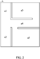
- FIG. 2 is a schematic diagram illustrating a plurality of areas of a positioning environment according to an embodiment of the invention. As shown in FIG. 2 , the positioning environment A may be divided into areas a1 ⁇ a5 in advance, and the information of areas a1 ⁇ a5 may be stored in the storage device 110, but the invention should not be limited thereto.
- the information of each area may be the information of an access point (AP) in each area. That is to say, in the embodiment each area may be equipped an AP and each AP may has its corresponding information.
- the information of each area stored in the storage device 110 may comprise one or more information discussed in the above embodiments, but the invention should not be limited thereto.
- the image positioning device 100 may obtain a plurality of images in a positioning environment from an image capturing device 200 (i.e. the images generated by the image capturing device 200 photographing different areas in the positioning environment), and position the images obtained from the image capturing device 200. Details are illustrated in the following embodiments.
- the image capturing device 200 may be an electronic device with a photography function, e.g. a cell phone, a camera or a dental mirror, but the invention should not be limited thereto.
- the image capturing device 200 may comprise an inertial measurement unit (IMU) to generate the IMU information (e.g. position and angle information) of each image generated by the image capturing device 200.
- IMU inertial measurement unit
- the image capturing device 200 may transmit the captured images and the information of the images to the image positioning device 100 through a wireless communication method, e.g. Bluetooth, WIFI or mobile communications (e.g. cellular network).
- the information corresponding to each image may comprise the time information, the signal strength information (e.g. the received signal strength indication (RSSI)) and the IMU information, but the invention should not be limited thereto, wherein the signal strength information of one image is the signal strength received by the image capturing device 200 when the image capturing device 200 generates this image.
- RSSI received signal strength indication
- the calculation circuit 120 of the image positioning device 100 may classify the images into a plurality of main groups based on the information corresponding to the areas and a first algorithm, wherein each main group may correspond to an area.
- the calculation circuit 120 may classify the images into a plurality of main groups based on the information corresponding to the areas a1 ⁇ a5 and the first algorithm, wherein the images corresponding to the area a1 may be regarded as a first main group, the images corresponding to the area a2 may be regarded as a second main group, the images corresponding to the area a3 may be regarded as a third main group, the images corresponding to the area a4 may be regarded as a fourth main group and the images corresponding to the area a5 may be regarded as a fifth main group, but the invention should not be limited thereto.
- the first algorithm may be a deep learning algorithm.
- the calculation circuit 120 of the image positioning device 100 may determine each image corresponds to which area based on the machine learning results stored in the storage device 110 and the deep learning algorithm to classify the images into multiple main groups.
- the first algorithm when the information corresponding to each area is the information of AP equipped in each area, the first algorithm may be a tingle positioning algorithm.
- the calculation circuit 120 may classify the images into multiple main groups based on the tingle positioning algorithm and the signal strength information received by the image capturing device 200 when the image capturing device 200 generates each image (i.e. the signal strength information between the image capturing device 200 and different APs).
- the feature capturing circuit 130 of the image positioning device 100 may capture the features of the images in each main group. Then, the calculation circuit 120 may classify the images in each main group into a plurality of sub-groups based on the features of the images in each main group and a clustering algorithm.
- the clustering algorithm may be a k-means algorithm, but the invention should not be limited thereto.
- the user can decide how many sub-groups need to be classified in one main group (i.e. decide the number of the sub-groups in each main group) in advance.
- each subgroup may correspond to one kernel of the k-means algorithm. That is to say, the number of the kernels may be equal to the number of the sub-groups.
- the feature capturing circuit 130 may generate a feature vector of each image in each main group based on deep learning algorithm, wherein each feature vector may be regarded as the feature of each image.
- the feature capturing circuit 130 may input each image in each main group to a deep learning algorithm model to obtain the feature vector of each image.
- the deep learning algorithm may be a Convolution Neural Network (CNN) algorithm (e.g. EfficientNet, ResNet, and so on), but the invention should not be limited thereto.
- the calculation circuit 120 may use the clustering algorithm (e.g. K-means algorithm) to classify the images in each main group into multiple sub-groups based on the feature vector of each image in each main group.
- the clustering algorithm e.g. K-means algorithm
- the feature capturing circuit 130 may sort the images in each main group based on the time sequence of the images. Then, the feature capturing circuit 130 may obtain the first relative moving distance between each image and its previous image in each main group based on the second algorithm. Then, in each main group, the feature capturing circuit 130 may obtain the second relative moving distance between each image and the first image based on the first relative moving distance between each image and its previous image, wherein the second relative moving distance between each image and the first image may be regarded as the feature of each image.
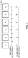
- FIG. 3 is a schematic diagram illustrating the second relative distance between each image and the first image in a main group according to an embodiment of the invention.
- the feature capturing circuit 130 may sort the images I 1 ⁇ I 6 in a main group based on the time sequence of the images I 1 ⁇ I 6 .
- the feature capturing circuit 130 may use the second algorithm to calculate the first relative moving distance between the image I 1 and image I 2 (1 unit moving distance, wherein the unit may be pixel, centimeter, meter, and so on), the first relative moving distance between the image I 2 and image I 3 (2 unit moving distance), the first relative moving distance between the image I 3 and image I 4 (3 unit moving distance), the first relative moving distance between the image I 4 and image I 5 (4 unit moving distance), and the first relative moving distance between the image I 5 and image I 6 (1 unit moving distance).
- the feature capturing circuit 130 may obtain the second relative moving distance between the image I 1 and image I 1 (0 unit moving distance), the second relative moving distance between the image I 2 and image I 1 (1 unit moving distance), the second relative moving distance between the image I 3 and image I 1 (3 unit moving distance), the second relative moving distance between the image I 4 and image I 1 (6 unit moving distance), the second relative moving distance between the image I 5 and image I 1 (10 unit moving distance), and the second relative moving distance between the image I 6 and image I 1 (11 unit moving distance).
- FIG. 3 is used to illustrate the embodiment of the invention, but the invention should not be limited thereto.
- the first relative moving distance and the second relative moving distance may be negative values.
- the second algorithm may be an image comparing algorithm or an IMU algorithm, but the invention should not be limited thereto.
- the feature capturing circuit 130 may use the image comparing algorithm to compare each image with its previous image in each main group (e.g. comparing the image I 2 with the image I 1 in FIG. 3 ) to obtain the first relative moving distance of each image.
- the second algorithm is the IMU algorithm
- the feature capturing circuit 130 may use the IMU algorithm to calculate the acceleration between each image and its previous image in each main group (e.g. obtain the acceleration between the image I 2 and the image I 1 in FIG. 3 ) to obtain the first relative moving distance of each image.
- the calculation circuit 120 may use the clustering algorithm (e.g. K-means algorithm) to classify the images in each main group into multiple sub-groups based on the second relative moving distance of each image in each main group.
- the clustering algorithm e.g. K-means algorithm
- the positioning circuit 140 may calculate the relative position relationship between each sub-group of each main group, and position each sub-group in the corresponding area of each main group based on the relative position relationship between each sub-group of each main group. Details are illustrated below.
- the positioning circuit 140 may calculate the relative position relationship between each sub-group of each main group based on an image comparing algorithm (or an IMU algorithm).
- the relative position relationship may a relative horizontal position relationship and/or a relative vertical position relationship.
- FIG. 4 is used as an example for illustration below.
- the positioning circuit 140 after the positioning circuit 140 knows the relative position relationship between each sub-group in one main group, the positioning circuit 140 will be able to position the sub-groups in the area corresponding to the main group.
- FIG. 4 is a schematic diagram illustrating a first sub-group and a second sub-group in a main group according to an embodiment of the invention.
- the first sub-group comprises p images and the second sub-group comprises q images.
- the positioning circuit 140 may use the image comparing algorithm to calculate the moving distances h 1,1 , h 1,2 ... and h 1,q between the first image P 1 of the first sub-group and all images Q 1 ⁇ Q q of the second sub-group, wherein h 1,1 means the moving distance between the first image P 1 of the first sub-group and the first image Q1 of the second sub-group.
- the positioning circuit 140 may know the relative position relationship between the first sub-group and the second sub-group based on the average value r.
- the average value r is greater than 0, it means that the first sub-group is on the right of the second sub-group (or above the second sub-group).
- the average value r is smaller than 0, it means that the first sub-group is on the left of the second sub-group (or below the second sub-group).
- the positioning circuit 140 may calculate the relative position relationship between each sub-group of each main group based on the second relative moving distance of each image in each main group and position the sub-groups in the area corresponding to each main group based on the relative position relationship between each sub-group in each main group.
- the relative position relationship may a relative horizontal position relationship and/or a relative vertical position relationship.
- the positioning circuit 140 may determine the relative position relationship between each sub-group and the image I 1 based on the average second relative moving distance of each sub-group to obtain the relative position relationship between the first sub-group, the second subgroup and the third sub-group. Specifically, when the average second relative moving distance of a sub-group is greater than 0, the positioning circuit 140 may determine that the sub-group is on the right of the image I 1 (or above the image I 1 ).
- the positioning circuit 140 may determine that the sub-group is on the left of the image I 1 (or below the image I 1 ). In addition, when the average second relative moving distance of a sub-group approaches to 0, the positioning circuit 140 may determine that the sub-group approaches to the image I 1 . When the average second relative moving distance of a sub-group is far away from 0, the positioning circuit 140 may determine that the sub-group is far away from the image I 1 . It should be noted that FIG. 3 is used to illustrate the embodiment of the invention, but the invention should not be limited thereto.
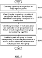
- FIG. 5 is a flow chart illustrating an image positioning method according to an embodiment of the invention.
- the image positioning method can be applied to the image positioning device 100.
- a calculation circuit of the image positioning device 100 obtains a plurality of images from an image capturing device.
- the calculation circuit of the image positioning device 100 may classify the images into a plurality of main groups based on a first algorithm and the information corresponding to a plurality of areas stored in a storage device of the image positioning device 100, wherein each main group may correspond to different area.
- step S530 the calculation circuit of the image positioning device 100 may classify the images in each main group into a plurality of sub-groups based on the feature of each image in each main group and a clustering algorithm.
- a positioning circuit of the image positioning device 100 may position the sub-groups of each main group in the area corresponding to each main group based on the relative position relationship between each sub-group of each main group.
- the first algorithm nay be a deep learning algorithm.
- the calculation circuit of the image positioning device 100 may classify the images into the main groups based on the deep learning algorithm.
- the information corresponding to the areas may comprise the information of an access point (AP) equipped in each area, and the first algorithm is a triangle positioning algorithm.
- the calculation circuit of the image positioning device 100 may classify the images into the main groups based on the signal strength of the AP equipped in each area and the triangle positioning algorithm.
- the image positioning method may further comprise that a feature capturing circuit of the image positioning device 100 may generate a feature vector of each image in each main group based on a deep learning algorithm, wherein each feature vector may be regarded as the feature of each image.
- the positioning circuit of the image positioning circuit 100 may classify the images in each main group into a plurality of sub-groups based on the feature vector of each image and the clustering algorithm.
- the positioning circuit of the image positioning circuit 100 may obtain the relative position relationship between each sub-group of each main group based on an image comparing algorithm, and position each sub-group of each main group according to the relative position relationship between each sub-group.
- the image positioning method further comprises that a feature capturing circuit of the image positioning device 100 may sort the images in each main group based on the time sequence of the images. Then, the feature capturing circuit of the image positioning device 100 may obtain the first relative moving distance between each image and its previous image in each main group based on the second algorithm. Then, the feature capturing circuit of the image positioning device 100 may obtain the second relative moving distance between each image and the first image in each main group based on the first relative moving distance corresponding to each image in each main group. The second relative moving distance between each image and the first image in each main group may be regarded as the feature of each image.
- the second algorithm may be an image comparing algorithm or an IMU algorithm.
- the positioning circuit of the image positioning device 100 may classify the images in each main group into multiple sub-groups based on the second relative moving distance corresponding to each image of each main group and the clustering algorithm.
- the poisoning circuit of the image positioning device 100 may obtain the relative position relationship between each sub-group based on the second relative moving distance corresponding to each image of each main group, and position each sub-group according to the relative position relationship between each sub-group.
- the clustering algorithm may be a k-means algorithm.
- a plurality of images can be classified into different main groups first, and the images of each main group can be classified into different sub-groups. Then, the relative position relationship between each sub-group of each main group will be used to position the sub-groups. Therefore, in the positioning method provided in the invention, the multiple images can be positioned more accurately in its corresponding environment.
- a software module e.g., including executable instructions and related data
- other data may reside in a data memory such as RAM memory, flash memory, ROM memory, EPROM memory, EEPROM memory, registers, a hard disk, a removable disk, a CD-ROM, or any other form of computer-readable storage medium known in the art.
- a sample storage medium may be coupled to a machine such as, for example, a computer/processor (which may be referred to herein, for convenience, as a "processor”) such that the processor can read information (e.g., code) from and write information to the storage medium.
- a sample storage medium may be integral to the processor.
- the processor and the storage medium may reside in an ASIC.
- the ASIC may reside in user equipment.
- the processor and the storage medium may reside as discrete components in user equipment.
- any suitable computer-program product may comprise a computer-readable medium comprising codes relating to one or more of the aspects of the disclosure.
- a computer program product may comprise packaging materials.
Landscapes
- Engineering & Computer Science (AREA)
- Theoretical Computer Science (AREA)
- Physics & Mathematics (AREA)
- General Physics & Mathematics (AREA)
- Data Mining & Analysis (AREA)
- Artificial Intelligence (AREA)
- Evolutionary Computation (AREA)
- Life Sciences & Earth Sciences (AREA)
- General Engineering & Computer Science (AREA)
- Computer Vision & Pattern Recognition (AREA)
- Computing Systems (AREA)
- Multimedia (AREA)
- Software Systems (AREA)
- General Health & Medical Sciences (AREA)
- Health & Medical Sciences (AREA)
- Bioinformatics & Cheminformatics (AREA)
- Evolutionary Biology (AREA)
- Bioinformatics & Computational Biology (AREA)
- Biophysics (AREA)
- Molecular Biology (AREA)
- Biomedical Technology (AREA)
- Computational Linguistics (AREA)
- Mathematical Physics (AREA)
- Probability & Statistics with Applications (AREA)
- Medical Informatics (AREA)
- Databases & Information Systems (AREA)
- Image Analysis (AREA)
- Supply And Installment Of Electrical Components (AREA)
- Image Processing (AREA)
- Vehicle Body Suspensions (AREA)
- Die Bonding (AREA)
- Exposure And Positioning Against Photoresist Photosensitive Materials (AREA)
Abstract
Description
- This Application claims priority of
TW Patent Application No. 110117031 filed on May 12, 2021 - The invention generally relates to image positioning technology, and more particularly, to image positioning technology in which image positioning is performed based on clustered images.
- As technology has progressed, positioning applications are being applied more widely. Therefore, how to generate a positioning result more accurately is a subject that is worthy of discussion.
- An image positioning device and method are provided to overcome the problems mentioned above.
- An embodiment of the invention provides an image positioning device. The image positioning device comprises a calculation circuit and a positioning circuit. The calculation circuit obtains a plurality of images from an image capturing device and classifies the images into a plurality of main groups based on a first algorithm, wherein each main group corresponds to a different area and the calculation circuit classifies the images of each main group into a plurality of sub-groups based on a feature of each image of each main group and a clustering algorithm. The positioning circuit is coupled to the calculation circuit. The positioning circuit positions each subgroup in the area corresponding to each main group based on the relative position relationship between each sub-group of each main group.
- In some embodiments, the first algorithm is a deep learning algorithm.
- In some embodiments, the first algorithm is a triangle positioning algorithm.
- In some embodiments, the image positioning device further comprises a feature capturing circuit. The feature capturing circuit is coupled to the calculation circuit. The feature capturing circuit generates a feature vector of each image of each main group, wherein the feature vector of each image is used as the feature of each image. The positioning circuit classifies the images in each main group into sub-groups based on the feature vector of each image of each main group and the clustering algorithm. In addition, the positioning circuit obtains the relative position relationship between each sub-group of each main group based on an image comparing algorithm, and positions each sub-group based on the relative position relationship.
- In some embodiments, the image positioning device further comprises a feature capturing circuit. The feature capturing circuit is coupled to the calculation circuit. The feature capturing circuit sorts the images in each main group based on the time sequence of each of the images. Then, the feature capturing circuit obtains the first relative moving distance between each image and its previous image in each main group based on the second algorithm. Then, the feature capturing circuit obtains the second relative moving distance between each image and the first image in each main group based on the first relative moving distance corresponding to each image in each main group. The second relative moving distance of each image is used as the feature of each image. In the embodiments, the second algorithm is an image comparing algorithm or an IMU algorithm. The positioning circuit may classify the images in each main group into sub-groups based on the second relative moving distance of each image of each main group and the clustering algorithm. In addition, the positioning circuit may obtain the relative position relationship between each sub-group in each main group based on the second relative moving distance of each image of each main group and positions each sub-group based on the relative position relationship.
- In some embodiments, the clustering algorithm is a k-means algorithm.
- An embodiment of the invention provides an image positioning method. The image positioning method is applied to an image positioning device The image positioning method comprises the steps of using a calculation circuit of the image positioning device to obtain a plurality of images from an image capturing device; using the calculation circuit to classify the images into a plurality of main groups based on a first algorithm, wherein each main group corresponds to a different area; using the calculation circuit to classify the images of each main group into a plurality of sub-groups based on a feature of each image of each main group and a clustering algorithm; and using a positioning circuit of the image positioning device to position each sub-group in the area corresponding to each main group based on the relative position relationship between each sub-group of each main group.
- Other aspects and features of the invention will become apparent to those with ordinary skill in the art upon review of the following descriptions of specific embodiments of an image positioning device and method.
- The invention will become more fully understood by referring to the following detailed description with reference to the accompanying drawings, wherein:
-
FIG. 1 is a block diagram of animage positioning device 100 according to an embodiment of the invention; -
FIG. 2 is a schematic diagram illustrating a plurality of areas of a positioning environment according to an embodiment of the invention; -
FIG. 3 is a schematic diagram illustrating the second relative distance between each image and the first image in a main group according to an embodiment of the invention; -
FIG. 4 is a schematic diagram illustrating a first sub-group and a second sub-group in a main group according to an embodiment of the invention; and -
FIG. 5 is a flow chart illustrating an image positioning method according to an embodiment of the invention. - The following description is of the best-contemplated mode of carrying out the invention. This description is made for the purpose of illustrating the general principles of the invention and should not be taken in a limiting sense. The scope of the invention is best determined by reference to the appended claims.
-
FIG. 1 is a block diagram of animage positioning device 100 according to an embodiment of the invention. As shown inFIG. 1 , theimage positioning device 100 may comprise astorage device 110, acalculation circuit 120, a feature capturingcircuit 130, and apositioning circuit 140. It should be noted thatFIG. 1 presents a simplified block diagram in which only the elements relevant to the invention are shown. However, the invention should not be limited to what is shown inFIG. 1 . Theimage positioning device 100 may also comprise other elements and the connections between the elements may be different from theimage positioning device 100. According to an embodiment of the invention, some or all of thecalculation circuit 120, the feature capturingcircuit 130, and thepositioning circuit 140 may be integrated in a chip. In another embodiment, thestorage device 110, thecalculation circuit 120, the feature capturingcircuit 130, and thepositioning circuit 140 may also be integrated in a chip. - According to the embodiments of the invention, the
storage device 110 may be a volatile memory (e.g. Random Access Memory (RAM)), or a non-volatile memory (e.g. flash memory, Read Only Memory (ROM)), a hard disk, or a combination of the above memory devices. Thestorage device 110 may store the required files and data for the image positioning, e.g. the information corresponding to a plurality of areas in a positioning environment, but the invention should not be limited thereto. - According to an embodiment of the invention, a positioning environment may be divided into a plurality of areas in advance, and the information of each area may be stored in the
storage device 110. According to the embodiments of the invention, the positioning environment may be an oral cavity, an interior space (e.g. an office) or an outdoor space, but the invention should not be limited thereto.FIG. 2 is a schematic diagram illustrating a plurality of areas of a positioning environment according to an embodiment of the invention. As shown inFIG. 2 , the positioning environment A may be divided into areas a1∼a5 in advance, and the information of areas a1∼a5 may be stored in thestorage device 110, but the invention should not be limited thereto. - According to an embodiment of the invention, the information of each area may be the information of an access point (AP) in each area. That is to say, in the embodiment each area may be equipped an AP and each AP may has its corresponding information. According to the embodiments of the invention, the information of each area stored in the
storage device 110 may comprise one or more information discussed in the above embodiments, but the invention should not be limited thereto. - According to an embodiment of the invention, the
image positioning device 100 may obtain a plurality of images in a positioning environment from an image capturing device 200 (i.e. the images generated by the image capturingdevice 200 photographing different areas in the positioning environment), and position the images obtained from the image capturingdevice 200. Details are illustrated in the following embodiments. - According to an embodiment of the invention, the
image capturing device 200 may be an electronic device with a photography function, e.g. a cell phone, a camera or a dental mirror, but the invention should not be limited thereto. According to an embodiment of the invention, theimage capturing device 200 may comprise an inertial measurement unit (IMU) to generate the IMU information (e.g. position and angle information) of each image generated by theimage capturing device 200. - According to an embodiment of the invention, the
image capturing device 200 may transmit the captured images and the information of the images to theimage positioning device 100 through a wireless communication method, e.g. Bluetooth, WIFI or mobile communications (e.g. cellular network). According to the embodiments of the invention, the information corresponding to each image may comprise the time information, the signal strength information (e.g. the received signal strength indication (RSSI)) and the IMU information, but the invention should not be limited thereto, wherein the signal strength information of one image is the signal strength received by theimage capturing device 200 when theimage capturing device 200 generates this image. - According to an embodiment of the invention, after the
image positioning device 100 obtains the images corresponding to a positioning environment from theimage capturing device 200, thecalculation circuit 120 of theimage positioning device 100 may classify the images into a plurality of main groups based on the information corresponding to the areas and a first algorithm, wherein each main group may correspond to an area. TakingFIG. 2 for example, thecalculation circuit 120 may classify the images into a plurality of main groups based on the information corresponding to the areas a1∼a5 and the first algorithm, wherein the images corresponding to the area a1 may be regarded as a first main group, the images corresponding to the area a2 may be regarded as a second main group, the images corresponding to the area a3 may be regarded as a third main group, the images corresponding to the area a4 may be regarded as a fourth main group and the images corresponding to the area a5 may be regarded as a fifth main group, but the invention should not be limited thereto. - According to an embodiment of the invention, the first algorithm may be a deep learning algorithm. The
calculation circuit 120 of theimage positioning device 100 may determine each image corresponds to which area based on the machine learning results stored in thestorage device 110 and the deep learning algorithm to classify the images into multiple main groups. - According to another embodiment of the invention, when the information corresponding to each area is the information of AP equipped in each area, the first algorithm may be a tingle positioning algorithm. The
calculation circuit 120 may classify the images into multiple main groups based on the tingle positioning algorithm and the signal strength information received by theimage capturing device 200 when theimage capturing device 200 generates each image (i.e. the signal strength information between theimage capturing device 200 and different APs). - According to an embodiment of the invention, after the
calculation circuit 120 classifies the images from theimage capturing device 200 into multiple main groups, thefeature capturing circuit 130 of theimage positioning device 100 may capture the features of the images in each main group. Then, thecalculation circuit 120 may classify the images in each main group into a plurality of sub-groups based on the features of the images in each main group and a clustering algorithm. - According to an embodiment of the invention, the clustering algorithm may be a k-means algorithm, but the invention should not be limited thereto. In the k-means algorithm, the user can decide how many sub-groups need to be classified in one main group (i.e. decide the number of the sub-groups in each main group) in advance. In addition, in the k-means algorithm, each subgroup may correspond to one kernel of the k-means algorithm. That is to say, the number of the kernels may be equal to the number of the sub-groups.
- According to an embodiment of the invention, the
feature capturing circuit 130 may generate a feature vector of each image in each main group based on deep learning algorithm, wherein each feature vector may be regarded as the feature of each image. Specifically, thefeature capturing circuit 130 may input each image in each main group to a deep learning algorithm model to obtain the feature vector of each image. In the embodiment, the deep learning algorithm may be a Convolution Neural Network (CNN) algorithm (e.g. EfficientNet, ResNet, and so on), but the invention should not be limited thereto. In addition, in the embodiment, after thefeature capturing circuit 130 obtains the feature vector of each image in each main group, thecalculation circuit 120 may use the clustering algorithm (e.g. K-means algorithm) to classify the images in each main group into multiple sub-groups based on the feature vector of each image in each main group. - According to another embodiment of the invention, the
feature capturing circuit 130 may sort the images in each main group based on the time sequence of the images. Then, thefeature capturing circuit 130 may obtain the first relative moving distance between each image and its previous image in each main group based on the second algorithm. Then, in each main group, thefeature capturing circuit 130 may obtain the second relative moving distance between each image and the first image based on the first relative moving distance between each image and its previous image, wherein the second relative moving distance between each image and the first image may be regarded as the feature of each image. - Taking
FIG. 3 for example,FIG. 3 is a schematic diagram illustrating the second relative distance between each image and the first image in a main group according to an embodiment of the invention. Thefeature capturing circuit 130 may sort the images I1∼I6 in a main group based on the time sequence of the images I1∼I6. Then, thefeature capturing circuit 130 may use the second algorithm to calculate the first relative moving distance between the image I1 and image I2 (1 unit moving distance, wherein the unit may be pixel, centimeter, meter, and so on), the first relative moving distance between the image I2 and image I3 (2 unit moving distance), the first relative moving distance between the image I3 and image I4 (3 unit moving distance), the first relative moving distance between the image I4 and image I5 (4 unit moving distance), and the first relative moving distance between the image I5 and image I6 (1 unit moving distance). Finally, thefeature capturing circuit 130 may obtain the second relative moving distance between the image I1 and image I1 (0 unit moving distance), the second relative moving distance between the image I2 and image I1 (1 unit moving distance), the second relative moving distance between the image I3 and image I1 (3 unit moving distance), the second relative moving distance between the image I4 and image I1 (6 unit moving distance), the second relative moving distance between the image I5 and image I1 (10 unit moving distance), and the second relative moving distance between the image I6 and image I1 (11 unit moving distance). It should be noted thatFIG. 3 is used to illustrate the embodiment of the invention, but the invention should not be limited thereto. The first relative moving distance and the second relative moving distance may be negative values. - According to the embodiments of the invention, the second algorithm may be an image comparing algorithm or an IMU algorithm, but the invention should not be limited thereto. When the second algorithm is the image comparing algorithm, the
feature capturing circuit 130 may use the image comparing algorithm to compare each image with its previous image in each main group (e.g. comparing the image I2 with the image I1 inFIG. 3 ) to obtain the first relative moving distance of each image. When the second algorithm is the IMU algorithm, thefeature capturing circuit 130 may use the IMU algorithm to calculate the acceleration between each image and its previous image in each main group (e.g. obtain the acceleration between the image I2 and the image I1 inFIG. 3 ) to obtain the first relative moving distance of each image. - In addition, in the embodiment, after the
feature capturing circuit 130 obtains the second relative moving distance of each image in each main group, thecalculation circuit 120 may use the clustering algorithm (e.g. K-means algorithm) to classify the images in each main group into multiple sub-groups based on the second relative moving distance of each image in each main group. - According to the embodiments of the invention, after the
calculation circuit 120 classify the images in each main group into multiple sub-groups, thepositioning circuit 140 may calculate the relative position relationship between each sub-group of each main group, and position each sub-group in the corresponding area of each main group based on the relative position relationship between each sub-group of each main group. Details are illustrated below. - According to an embodiment of the invention, when the
calculation circuit 120 uses the clustering algorithm (e.g. k-means algorithm) classify the images in each main group into multiple sub-groups based on the feature vector of each image in each main group, thepositioning circuit 140 may calculate the relative position relationship between each sub-group of each main group based on an image comparing algorithm (or an IMU algorithm). In the embodiment, the relative position relationship may a relative horizontal position relationship and/or a relative vertical position relationship.FIG. 4 is used as an example for illustration below. In the embodiment, after thepositioning circuit 140 knows the relative position relationship between each sub-group in one main group, thepositioning circuit 140 will be able to position the sub-groups in the area corresponding to the main group. -
FIG. 4 is a schematic diagram illustrating a first sub-group and a second sub-group in a main group according to an embodiment of the invention. As shown inFIG. 4 , the first sub-group comprises p images and the second sub-group comprises q images. Thepositioning circuit 140 may use the image comparing algorithm to calculate the moving distances h1,1, h1,2... and h1,q between the first image P1 of the first sub-group and all images Q1∼Qq of the second sub-group, wherein h1,1 means the moving distance between the first image P1 of the first sub-group and the first image Q1 of the second sub-group. Then, thepositioning circuit 140 may take average for the moving distances h1,1, h1,2...and h1,q to obtain the average moving distance m1 between the first image P1 of the first sub-group and all images Q1∼Qq of the second sub-group (i.e. m1=( h1,1+h1,2+...+h1,q)/q). Accordingly, thepositioning circuit 140 may calculate the average moving distances m1, m2,...mp between each of the images P1∼Pp of the first sub-group and all images Q1∼Qq of the second sub-group. Then, thepositioning circuit 140 may take average for the average moving distances m1, m2,...mp to obtain an average value r (i.e. r=( m1+m2+...+mp)/p). Thepositioning circuit 140 may know the relative position relationship between the first sub-group and the second sub-group based on the average value r. When the average value r is greater than 0, it means that the first sub-group is on the right of the second sub-group (or above the second sub-group). When the average value r is smaller than 0, it means that the first sub-group is on the left of the second sub-group (or below the second sub-group). - According to another embodiment of the invention, when the
calculation circuit 120 uses the clustering algorithm (e.g. k-means algorithm) classify the images in each main group into multiple sub-groups based on the second relative moving distance of each image in each main group, thepositioning circuit 140 may calculate the relative position relationship between each sub-group of each main group based on the second relative moving distance of each image in each main group and position the sub-groups in the area corresponding to each main group based on the relative position relationship between each sub-group in each main group. In the embodiment, the relative position relationship may a relative horizontal position relationship and/or a relative vertical position relationship. - As shown in
FIG. 3 , it is assumed that the image I1, image I2 and image I3 are in the first sub-group, the image I4 is in the second sub-group and the image I5 and image I6 are in the third sub group. Thepositioning circuit 140 may determine the relative position relationship between each sub-group and the image I1 based on the average second relative moving distance of each sub-group to obtain the relative position relationship between the first sub-group, the second subgroup and the third sub-group. Specifically, when the average second relative moving distance of a sub-group is greater than 0, thepositioning circuit 140 may determine that the sub-group is on the right of the image I1 (or above the image I1). When the average second relative moving distance of a sub-group is smaller than 0, thepositioning circuit 140 may determine that the sub-group is on the left of the image I1 (or below the image I1). In addition, when the average second relative moving distance of a sub-group approaches to 0, thepositioning circuit 140 may determine that the sub-group approaches to the image I1. When the average second relative moving distance of a sub-group is far away from 0, thepositioning circuit 140 may determine that the sub-group is far away from the image I1. It should be noted thatFIG. 3 is used to illustrate the embodiment of the invention, but the invention should not be limited thereto. -
FIG. 5 is a flow chart illustrating an image positioning method according to an embodiment of the invention. The image positioning method can be applied to theimage positioning device 100. As shown inFIG. 5 , in step S510, a calculation circuit of theimage positioning device 100 obtains a plurality of images from an image capturing device. - In step S520, the calculation circuit of the
image positioning device 100 may classify the images into a plurality of main groups based on a first algorithm and the information corresponding to a plurality of areas stored in a storage device of theimage positioning device 100, wherein each main group may correspond to different area. - In step S530, the calculation circuit of the
image positioning device 100 may classify the images in each main group into a plurality of sub-groups based on the feature of each image in each main group and a clustering algorithm. - In step S540, a positioning circuit of the
image positioning device 100 may position the sub-groups of each main group in the area corresponding to each main group based on the relative position relationship between each sub-group of each main group. - According to some embodiments of the invention, in the image positioning method, the first algorithm nay be a deep learning algorithm. The calculation circuit of the
image positioning device 100 may classify the images into the main groups based on the deep learning algorithm. - According to some embodiments of the invention, in the image positioning method, the information corresponding to the areas may comprise the information of an access point (AP) equipped in each area, and the first algorithm is a triangle positioning algorithm. In the image positioning method, the calculation circuit of the
image positioning device 100 may classify the images into the main groups based on the signal strength of the AP equipped in each area and the triangle positioning algorithm. - According to some embodiments of the invention, the image positioning method may further comprise that a feature capturing circuit of the
image positioning device 100 may generate a feature vector of each image in each main group based on a deep learning algorithm, wherein each feature vector may be regarded as the feature of each image. In the embodiments, the positioning circuit of theimage positioning circuit 100 may classify the images in each main group into a plurality of sub-groups based on the feature vector of each image and the clustering algorithm. In the embodiments, the positioning circuit of theimage positioning circuit 100 may obtain the relative position relationship between each sub-group of each main group based on an image comparing algorithm, and position each sub-group of each main group according to the relative position relationship between each sub-group. - According to some embodiments of the invention, the image positioning method further comprises that a feature capturing circuit of the
image positioning device 100 may sort the images in each main group based on the time sequence of the images. Then, the feature capturing circuit of theimage positioning device 100 may obtain the first relative moving distance between each image and its previous image in each main group based on the second algorithm. Then, the feature capturing circuit of theimage positioning device 100 may obtain the second relative moving distance between each image and the first image in each main group based on the first relative moving distance corresponding to each image in each main group. The second relative moving distance between each image and the first image in each main group may be regarded as the feature of each image. - In the embodiments, the second algorithm may be an image comparing algorithm or an IMU algorithm. In the embodiments, the positioning circuit of the
image positioning device 100 may classify the images in each main group into multiple sub-groups based on the second relative moving distance corresponding to each image of each main group and the clustering algorithm. - In the embodiments, the poisoning circuit of the
image positioning device 100 may obtain the relative position relationship between each sub-group based on the second relative moving distance corresponding to each image of each main group, and position each sub-group according to the relative position relationship between each sub-group. - According to some embodiments of the invention, the clustering algorithm may be a k-means algorithm.
- According to the positioning method provided in the invention, a plurality of images can be classified into different main groups first, and the images of each main group can be classified into different sub-groups. Then, the relative position relationship between each sub-group of each main group will be used to position the sub-groups. Therefore, in the positioning method provided in the invention, the multiple images can be positioned more accurately in its corresponding environment.
- Use of ordinal terms such as "first", "second", "third", etc., in the disclosure and claims is for description. It does not by itself connote any order or relationship.
- The steps of the method described in connection with the aspects disclosed herein may be embodied directly in hardware, in a software module executed by a processor, or in a combination of the two. A software module (e.g., including executable instructions and related data) and other data may reside in a data memory such as RAM memory, flash memory, ROM memory, EPROM memory, EEPROM memory, registers, a hard disk, a removable disk, a CD-ROM, or any other form of computer-readable storage medium known in the art. A sample storage medium may be coupled to a machine such as, for example, a computer/processor (which may be referred to herein, for convenience, as a "processor") such that the processor can read information (e.g., code) from and write information to the storage medium. A sample storage medium may be integral to the processor. The processor and the storage medium may reside in an ASIC. The ASIC may reside in user equipment. Alternatively, the processor and the storage medium may reside as discrete components in user equipment. Moreover, in some aspects any suitable computer-program product may comprise a computer-readable medium comprising codes relating to one or more of the aspects of the disclosure. In some aspects a computer program product may comprise packaging materials.
- The above paragraphs describe many aspects. Obviously, the teaching of the invention can be accomplished by many methods, and any specific configurations or functions in the disclosed embodiments only present a representative condition. Those who are skilled in this technology will understand that all of the disclosed aspects in the invention can be applied independently or be incorporated.
- While the invention has been described by way of example and in terms of preferred embodiment, it should be understood that the invention is not limited thereto. Those who are skilled in this technology can still make various alterations and modifications without departing from the scope and spirit of this invention. Therefore, the scope of the present invention shall be defined and protected by the following claims and their equivalents.
Claims (15)
- An image positioning device, comprising:a calculation circuit, wherein the calculation circuit obtains a plurality of images from an image capturing device and classifies the images into a plurality of main groups based on a first algorithm, wherein each main group corresponds to a different area and the calculation circuit classifies the images of each main group into a plurality of sub-groups based on a feature of each image of each main group and a clustering algorithm; anda positioning circuit, coupled to the calculation circuit, wherein the positioning circuit positions each sub-group in the area corresponding to each main group based on a relative position relationship between each sub-group of each main group.
- The image positioning device of claim 1, further comprising:
a feature capturing circuit, coupled to the calculation circuit and generating a feature vector of each image of each main group, wherein the feature vector of each image is taken as the feature of each image. - The image positioning device of claim 2, wherein the positioning circuit classifies the images in each main group into the plurality of sub-groups based on the feature vector of each image of each main group and the clustering algorithm.
- The image positioning device of any of claims 1 to 3, wherein the positioning circuit obtains the relative position relationship between each sub-group of each main group based on an image comparing algorithm, and positions each sub-group based on the relative position relationship.
- The image positioning device of claim 1, further comprising:
a feature capturing circuit, coupled to the calculation circuit and sorting the images in each main group based on a time sequence of each image, obtaining a first relative moving distance between each image and its previous image in each main group based on a second algorithm, and obtaining a second relative moving distance between each image and the first image in each main group based on the first relative moving distance corresponding to each image in each main group, wherein the second relative moving distance of each image is taken as the feature of each image. - The image positioning device of claim 5, wherein the second algorithm is an image comparing algorithm or an IMU algorithm.
- The image positioning device of claim 5 or 6, wherein the positioning circuit classifies the images in each main group into the plurality of sub-groups based on the second relative moving distance of each image of each main group and the clustering algorithm.
- The image positioning device of claim 7, wherein the positioning circuit obtains the relative position relationship between each sub-group in each main group based on the second relative moving distance of each image of each main group and positions each sub-group based on the relative position relationship.
- An image positioning method, applied to an image positioning device, comprising:obtaining, by a calculation circuit of the image positioning device, a plurality of images from an image capturing device;classifying, by the calculation circuit, the images into a plurality of main groups based on a first algorithm, wherein each main group corresponds to a different area;classifying, by the calculation circuit, the images of each main group into a plurality of sub-groups based on a feature of each image of each main group and a clustering algorithm; andpositioning, by a positioning circuit of the image positioning device, each sub-group in the area corresponding to each main group based on a relative position relationship between each sub-group of each main group.
- The image positioning method of claim 9, further comprising:
generating, by a feature capturing circuit of the image positioning device, a feature vector of each image of each main group, wherein the feature vector of each image is taken as the feature of each image. - The image positioning method of claim 10, further comprising:
classifying, by the positioning circuit, the images in each main group into the plurality of sub-groups based on the feature vector of each image of each main group and the clustering algorithm. - The image positioning method of any of claims 9 to 11, further comprising:obtaining, by the positioning circuit, the relative position relationship between each sub-group of each main group based on an image comparing algorithm; andpositioning, by the positioning circuit, each sub-group based on the relative position relationship.
- The image positioning method of claim 9, further comprising:sorting, by a feature capturing circuit of the image positioning device, the images in each main group based on a time sequence of each image;obtaining, by the feature capturing circuit, a first relative moving distance between each image and its previous image in each main group based on a second algorithm; andobtaining, by the feature capturing circuit, a second relative moving distance between each image and the first image in each main group based on the first relative moving distance corresponding to each image in each main group, wherein the second relative moving distance of each image is taken as the feature of each image.
- The image positioning method of claim 13, further comprising:
classifying, by the positioning circuit, the images in each main group into the plurality of sub-groups based on the second relative moving distance of each image of each main group and the clustering algorithm. - The image positioning method of claim 14, further comprising:
obtaining, by the positioning circuit, the relative position relationship between each sub-group in each main group based on the second relative moving distance of each image of each main group and positions each sub-group based on the relative position relationship.
Applications Claiming Priority (1)
| Application Number | Priority Date | Filing Date | Title |
|---|---|---|---|
| TW110117031A TWI772020B (en) | 2021-05-12 | 2021-05-12 | Image positioning device and method |
Publications (2)
| Publication Number | Publication Date |
|---|---|
| EP4089646A1 true EP4089646A1 (en) | 2022-11-16 |
| EP4089646B1 EP4089646B1 (en) | 2025-11-19 |
Family
ID=77640346
Family Applications (1)
| Application Number | Title | Priority Date | Filing Date |
|---|---|---|---|
| EP21193161.3A Active EP4089646B1 (en) | 2021-05-12 | 2021-08-26 | Image positioning device and method |
Country Status (4)
| Country | Link |
|---|---|
| US (1) | US11907340B2 (en) |
| EP (1) | EP4089646B1 (en) |
| CN (1) | CN115346103B (en) |
| TW (1) | TWI772020B (en) |
Family Cites Families (8)
| Publication number | Priority date | Publication date | Assignee | Title |
|---|---|---|---|---|
| WO2007020897A1 (en) * | 2005-08-17 | 2007-02-22 | Matsushita Electric Industrial Co., Ltd. | Video scene classification device and video scene classification method |
| US8311556B2 (en) * | 2009-01-22 | 2012-11-13 | Htc Corporation | Method and system for managing images and geographic location data in a mobile device |
| TWI530805B (en) * | 2013-08-22 | 2016-04-21 | 宇瞻科技股份有限公司 | Method and system for sorting pictures base on timing, and computer readable recording media |
| EP3228985B1 (en) * | 2014-05-05 | 2024-12-18 | Hexagon Technology Center GmbH | Surveying system |
| CN104616026B (en) * | 2015-01-20 | 2017-12-12 | 衢州学院 | A kind of monitoring scene type discrimination method towards intelligent video monitoring |
| WO2018078408A1 (en) * | 2016-10-28 | 2018-05-03 | The Nielsen Company (Us), Llc | Reducing scale estimate errors in shelf images |
| US10839220B2 (en) * | 2018-10-15 | 2020-11-17 | Kepler Vision Technologies B.V. | Method for categorizing a scene comprising a sub-scene with machine learning |
| TWI684956B (en) * | 2018-12-04 | 2020-02-11 | 中華電信股份有限公司 | Object recognition and tracking system and method thereof |
-
2021
- 2021-05-12 TW TW110117031A patent/TWI772020B/en active
- 2021-05-28 CN CN202110591096.3A patent/CN115346103B/en active Active
- 2021-07-30 US US17/389,623 patent/US11907340B2/en active Active
- 2021-08-26 EP EP21193161.3A patent/EP4089646B1/en active Active
Non-Patent Citations (2)
| Title |
|---|
| JIANG WENCHAO ET AL: "Indoor localization with a signal tree", 2015 18TH INTERNATIONAL CONFERENCE ON INFORMATION FUSION (FUSION), ISIF, 6 July 2015 (2015-07-06), pages 1724 - 1731, XP033204892 * |
| SINGH GAURAV ET AL: "Fusing Semantics and Motion State Detection for Robust Visual SLAM", 2020 IEEE WINTER CONFERENCE ON APPLICATIONS OF COMPUTER VISION (WACV), IEEE, 1 March 2020 (2020-03-01), pages 2753 - 2762, XP033771007, DOI: 10.1109/WACV45572.2020.9093359 * |
Also Published As
| Publication number | Publication date |
|---|---|
| EP4089646B1 (en) | 2025-11-19 |
| CN115346103A (en) | 2022-11-15 |
| US20220366183A1 (en) | 2022-11-17 |
| TW202244846A (en) | 2022-11-16 |
| TWI772020B (en) | 2022-07-21 |
| US11907340B2 (en) | 2024-02-20 |
| CN115346103B (en) | 2025-10-10 |
Similar Documents
| Publication | Publication Date | Title |
|---|---|---|
| EP3843035B1 (en) | Image processing method and apparatus for target recognition | |
| CN110427800B (en) | Video object acceleration detection method, device, server and storage medium | |
| US8798378B1 (en) | Scene classification for place recognition | |
| CN108460362B (en) | System and method for detecting human body part | |
| US20210374447A1 (en) | Method and device for processing image, electronic equipment, and storage medium | |
| CN108629354B (en) | Object detection method and device | |
| CN108897757B (en) | Photo storage method, storage medium and server | |
| CN110660066A (en) | Network training method, image processing method, network, terminal equipment and medium | |
| US11475879B2 (en) | Method and device for evaluating quality of content, electronic equipment, and storage medium | |
| WO2021208667A1 (en) | Image processing method and apparatus, electronic device, and storage medium | |
| US11288307B2 (en) | Method, electronic device, and computer readable medium for photo organization | |
| CN109166156B (en) | Camera calibration image generation method, mobile terminal and storage medium | |
| EP4468724A1 (en) | Image processing method and apparatus, terminal device and storage medium | |
| CN113177917B (en) | A method, system, equipment and medium for capturing captured images | |
| CN115439875B (en) | Posture assessment devices, methods and systems | |
| CN112036345B (en) | Detection methods, recommended methods, detection systems and media for the number of people in target places | |
| CN110502982A (en) | The method, apparatus and computer equipment of barrier in a kind of detection highway | |
| CN112631333B (en) | Target tracking method and device of unmanned aerial vehicle and image processing chip | |
| TW201913484A (en) | Image display method and device and electronic device | |
| CN107193820B (en) | Location information acquisition method, device and device | |
| CN117710232A (en) | Traffic target fusion method, electronic device and storage medium | |
| US12450921B2 (en) | Method and apparatus for calibrating roll angle of on-board camera, device, and storage medium | |
| EP3461138A1 (en) | Processing method and terminal | |
| US11907340B2 (en) | Image positioning device and method | |
| CN111476214A (en) | Image area matching method and related device |
Legal Events
| Date | Code | Title | Description |
|---|---|---|---|
| PUAI | Public reference made under article 153(3) epc to a published international application that has entered the european phase |
Free format text: ORIGINAL CODE: 0009012 |
|
| STAA | Information on the status of an ep patent application or granted ep patent |
Free format text: STATUS: REQUEST FOR EXAMINATION WAS MADE |
|
| 17P | Request for examination filed |
Effective date: 20220325 |
|
| AK | Designated contracting states |
Kind code of ref document: A1 Designated state(s): AL AT BE BG CH CY CZ DE DK EE ES FI FR GB GR HR HU IE IS IT LI LT LU LV MC MK MT NL NO PL PT RO RS SE SI SK SM TR |
|
| STAA | Information on the status of an ep patent application or granted ep patent |
Free format text: STATUS: EXAMINATION IS IN PROGRESS |
|
| 17Q | First examination report despatched |
Effective date: 20230613 |
|
| GRAP | Despatch of communication of intention to grant a patent |
Free format text: ORIGINAL CODE: EPIDOSNIGR1 |
|
| STAA | Information on the status of an ep patent application or granted ep patent |
Free format text: STATUS: GRANT OF PATENT IS INTENDED |
|
| INTG | Intention to grant announced |
Effective date: 20250725 |
|
| P01 | Opt-out of the competence of the unified patent court (upc) registered |
Free format text: CASE NUMBER: UPC_APP_3782_4089646/2025 Effective date: 20250820 |
|
| GRAS | Grant fee paid |
Free format text: ORIGINAL CODE: EPIDOSNIGR3 |
|
| GRAA | (expected) grant |
Free format text: ORIGINAL CODE: 0009210 |
|
| STAA | Information on the status of an ep patent application or granted ep patent |
Free format text: STATUS: THE PATENT HAS BEEN GRANTED |
|
| AK | Designated contracting states |
Kind code of ref document: B1 Designated state(s): AL AT BE BG CH CY CZ DE DK EE ES FI FR GB GR HR HU IE IS IT LI LT LU LV MC MK MT NL NO PL PT RO RS SE SI SK SM TR |
|
| REG | Reference to a national code |
Ref country code: CH Ref legal event code: F10 Free format text: ST27 STATUS EVENT CODE: U-0-0-F10-F00 (AS PROVIDED BY THE NATIONAL OFFICE) Effective date: 20251119 Ref country code: GB Ref legal event code: FG4D |
|
| REG | Reference to a national code |
Ref country code: DE Ref legal event code: R096 Ref document number: 602021042537 Country of ref document: DE |
|
| REG | Reference to a national code |
Ref country code: IE Ref legal event code: FG4D |
|
| REG | Reference to a national code |
Ref country code: NL Ref legal event code: MP Effective date: 20251119 |
|
| PG25 | Lapsed in a contracting state [announced via postgrant information from national office to epo] |
Ref country code: ES Free format text: LAPSE BECAUSE OF FAILURE TO SUBMIT A TRANSLATION OF THE DESCRIPTION OR TO PAY THE FEE WITHIN THE PRESCRIBED TIME-LIMIT Effective date: 20251119 |
|
| REG | Reference to a national code |
Ref country code: LT Ref legal event code: MG9D |
|
| PG25 | Lapsed in a contracting state [announced via postgrant information from national office to epo] |
Ref country code: NO Free format text: LAPSE BECAUSE OF FAILURE TO SUBMIT A TRANSLATION OF THE DESCRIPTION OR TO PAY THE FEE WITHIN THE PRESCRIBED TIME-LIMIT Effective date: 20260219 |
|
| PG25 | Lapsed in a contracting state [announced via postgrant information from national office to epo] |
Ref country code: HR Free format text: LAPSE BECAUSE OF FAILURE TO SUBMIT A TRANSLATION OF THE DESCRIPTION OR TO PAY THE FEE WITHIN THE PRESCRIBED TIME-LIMIT Effective date: 20251119 Ref country code: FI Free format text: LAPSE BECAUSE OF FAILURE TO SUBMIT A TRANSLATION OF THE DESCRIPTION OR TO PAY THE FEE WITHIN THE PRESCRIBED TIME-LIMIT Effective date: 20251119 Ref country code: AT Free format text: LAPSE BECAUSE OF FAILURE TO SUBMIT A TRANSLATION OF THE DESCRIPTION OR TO PAY THE FEE WITHIN THE PRESCRIBED TIME-LIMIT Effective date: 20251119 |
|
| REG | Reference to a national code |
Ref country code: AT Ref legal event code: MK05 Ref document number: 1859527 Country of ref document: AT Kind code of ref document: T Effective date: 20251119 |
|
| PG25 | Lapsed in a contracting state [announced via postgrant information from national office to epo] |
Ref country code: NL Free format text: LAPSE BECAUSE OF FAILURE TO SUBMIT A TRANSLATION OF THE DESCRIPTION OR TO PAY THE FEE WITHIN THE PRESCRIBED TIME-LIMIT Effective date: 20251119 |
|
| PG25 | Lapsed in a contracting state [announced via postgrant information from national office to epo] |
Ref country code: RS Free format text: LAPSE BECAUSE OF FAILURE TO SUBMIT A TRANSLATION OF THE DESCRIPTION OR TO PAY THE FEE WITHIN THE PRESCRIBED TIME-LIMIT Effective date: 20260219 |
|
| PG25 | Lapsed in a contracting state [announced via postgrant information from national office to epo] |
Ref country code: IS Free format text: LAPSE BECAUSE OF FAILURE TO SUBMIT A TRANSLATION OF THE DESCRIPTION OR TO PAY THE FEE WITHIN THE PRESCRIBED TIME-LIMIT Effective date: 20260319 |
|
| PG25 | Lapsed in a contracting state [announced via postgrant information from national office to epo] |
Ref country code: PT Free format text: LAPSE BECAUSE OF FAILURE TO SUBMIT A TRANSLATION OF THE DESCRIPTION OR TO PAY THE FEE WITHIN THE PRESCRIBED TIME-LIMIT Effective date: 20260319 |
|
| PG25 | Lapsed in a contracting state [announced via postgrant information from national office to epo] |
Ref country code: PL Free format text: LAPSE BECAUSE OF FAILURE TO SUBMIT A TRANSLATION OF THE DESCRIPTION OR TO PAY THE FEE WITHIN THE PRESCRIBED TIME-LIMIT Effective date: 20251119 |
|
| PG25 | Lapsed in a contracting state [announced via postgrant information from national office to epo] |
Ref country code: LV Free format text: LAPSE BECAUSE OF FAILURE TO SUBMIT A TRANSLATION OF THE DESCRIPTION OR TO PAY THE FEE WITHIN THE PRESCRIBED TIME-LIMIT Effective date: 20251119 |
|
| PG25 | Lapsed in a contracting state [announced via postgrant information from national office to epo] |
Ref country code: BG Free format text: LAPSE BECAUSE OF FAILURE TO SUBMIT A TRANSLATION OF THE DESCRIPTION OR TO PAY THE FEE WITHIN THE PRESCRIBED TIME-LIMIT Effective date: 20251119 |