EP4089635B1 - Image analyzation method and image analyzation device - Google Patents
Image analyzation method and image analyzation device Download PDFInfo
- Publication number
- EP4089635B1 EP4089635B1 EP21203697.4A EP21203697A EP4089635B1 EP 4089635 B1 EP4089635 B1 EP 4089635B1 EP 21203697 A EP21203697 A EP 21203697A EP 4089635 B1 EP4089635 B1 EP 4089635B1
- Authority
- EP
- European Patent Office
- Prior art keywords
- image
- target region
- endpoint
- central point
- analyzation
- Prior art date
- Legal status (The legal status is an assumption and is not a legal conclusion. Google has not performed a legal analysis and makes no representation as to the accuracy of the status listed.)
- Active
Links
Images



Classifications
-
- G—PHYSICS
- G06—COMPUTING OR CALCULATING; COUNTING
- G06T—IMAGE DATA PROCESSING OR GENERATION, IN GENERAL
- G06T7/00—Image analysis
- G06T7/10—Segmentation; Edge detection
- G06T7/12—Edge-based segmentation
-
- G—PHYSICS
- G06—COMPUTING OR CALCULATING; COUNTING
- G06T—IMAGE DATA PROCESSING OR GENERATION, IN GENERAL
- G06T7/00—Image analysis
- G06T7/70—Determining position or orientation of objects or cameras
-
- G—PHYSICS
- G06—COMPUTING OR CALCULATING; COUNTING
- G06T—IMAGE DATA PROCESSING OR GENERATION, IN GENERAL
- G06T7/00—Image analysis
- G06T7/10—Segmentation; Edge detection
- G06T7/11—Region-based segmentation
-
- G—PHYSICS
- G06—COMPUTING OR CALCULATING; COUNTING
- G06T—IMAGE DATA PROCESSING OR GENERATION, IN GENERAL
- G06T7/00—Image analysis
- G06T7/60—Analysis of geometric attributes
- G06T7/62—Analysis of geometric attributes of area, perimeter, diameter or volume
-
- G—PHYSICS
- G06—COMPUTING OR CALCULATING; COUNTING
- G06V—IMAGE OR VIDEO RECOGNITION OR UNDERSTANDING
- G06V10/00—Arrangements for image or video recognition or understanding
- G06V10/20—Image preprocessing
- G06V10/22—Image preprocessing by selection of a specific region containing or referencing a pattern; Locating or processing of specific regions to guide the detection or recognition
-
- G—PHYSICS
- G06—COMPUTING OR CALCULATING; COUNTING
- G06T—IMAGE DATA PROCESSING OR GENERATION, IN GENERAL
- G06T2207/00—Indexing scheme for image analysis or image enhancement
- G06T2207/10—Image acquisition modality
- G06T2207/10116—X-ray image
-
- G—PHYSICS
- G06—COMPUTING OR CALCULATING; COUNTING
- G06T—IMAGE DATA PROCESSING OR GENERATION, IN GENERAL
- G06T2207/00—Indexing scheme for image analysis or image enhancement
- G06T2207/20—Special algorithmic details
- G06T2207/20112—Image segmentation details
- G06T2207/20132—Image cropping
-
- G—PHYSICS
- G06—COMPUTING OR CALCULATING; COUNTING
- G06T—IMAGE DATA PROCESSING OR GENERATION, IN GENERAL
- G06T2207/00—Indexing scheme for image analysis or image enhancement
- G06T2207/20—Special algorithmic details
- G06T2207/20112—Image segmentation details
- G06T2207/20164—Salient point detection; Corner detection
-
- G—PHYSICS
- G06—COMPUTING OR CALCULATING; COUNTING
- G06T—IMAGE DATA PROCESSING OR GENERATION, IN GENERAL
- G06T2207/00—Indexing scheme for image analysis or image enhancement
- G06T2207/30—Subject of image; Context of image processing
- G06T2207/30004—Biomedical image processing
- G06T2207/30008—Bone
- G06T2207/30012—Spine; Backbone
Definitions
- the disclosure relates to an image analyzation technology, and more particularly, to an image analyzation method and an image analyzation device.
- NGUYEN THONG PHI ET AL "Deep learning system for Meyerding classification and segmental motion measurement in diagnosis of lumbar spondylolisthesis", BIOMEDICAL SIGNAL PROCESSING AND CONTROL, ELSEVIER, AMSTERDAM, NL, vol. 65, 28 November 2020 mainly concerns the development of a deep learning system with supported by the convolutional neural network (CNN), in which the supplementary CNN model is trained to re-correct the keypoints located on corners of vertebra based on the first CNN regression model, to precisely measure required characteristics.
- CNN convolutional neural network
- the measurement ability of the proposed method is also required to adapt to multiple lateral bending views including flexion and extension postures.
- WO 01/55965 A2 discloses a method for extracting geometrical data from a 2-D digital image of the spine, comprising steps for determining spine outlines, endplates and corners wherein: digitizing the spine center line and end points; constructing a 2-D image band, referred to as Rubber-Band, whose center line is a spline representing the spine center line, and unfolding said Rubber-Band for constructing a 2-D Rectangular-Band; processing the 2-D Rectangular-Band image data in order to estimate best paths going through selected points for determining the spine outlines, then the endplates based on the found outline data and the corners at the intersection of the outlines and endplates.
- the invention provides an image analyzation method according to claim 1 and an image analyzation device according to claim 6, which may improve an accuracy of automated image analyzation.
- Advantageous embodiments are the subject of the dependent claims.
- An embodiment of the disclosure provides an image analyzation method carried out by an image analyzation device, which includes the following steps.
- a first image which is an X-ray image is obtained, and at least a first object and a second object are presented in the first image.
- the first image is analyzed to detect a first central point between a first endpoint of the first object and a second endpoint of the second object.
- a target region is determined in the first image based on the first central point as a center of the target region.
- a second image located in the target region is captured from the first image.
- the second image is analyzed to generate status information, and the status information reflects a gap status between the first object and the second object.
- An embodiment of the disclosure further provides an image analyzation device, which includes a processor and a storage circuit.
- the processor is coupled to the storage circuit.
- the processor is coupled to the storage circuit.
- the processor is configured to: obtain a first image which is an X-ray image, and at least a first object and a second object are presented in the first image; analyze the first image to detect a first central point between a first endpoint of the first object and a second endpoint of the second object; determine a target region in the first image based the first central point as a center of the target region; capture a second image located in the target region from the first image; and analyze the second image to generate status information, and the status information reflects a gap status between the first object and the second object.
- the first central point between the first endpoint of the first object in the first image and the second endpoint of the second object in the first image may be detected, and the target region may be automatically determined in the first image based on the first central point as the center of the target region.
- the second image located in the target region may be captured from the first image and analyzed to generate the status information.
- the status information reflects the gap status between the first object and the second object. In this way, the accuracy of the automated image analyzation may be effectively improved.
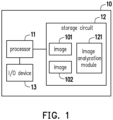
- FIG. 1 is a schematic view of an image analyzation device according to an embodiment of the disclosure.
- a device also referred to as an image analyzation device
- the device 10 may be any electronic device or computer device with image analyzation and calculation functions.
- the device 10 may also be an X-ray inspection device or an X-ray scanner (referred to as an X-ray machine).
- the device 10 includes a processor 11, a storage circuit 12, and an input/output (I/O) device 13.
- the processor 11 is coupled to the storage circuit 12 and the I/O device 13.
- the processor 11 is configured to be responsible for the overall or partial operation of the device 10.
- the processor 11 may include a central processing unit (CPU), a graphics processing unit (GPU), other programmable general-purpose or special-purpose microprocessors, a digital signal processor (DSP), a programmable controller, an application specific integrated circuit (ASIC), a programmable logic device PLD), other similar devices, or a combination of the devices.
- CPU central processing unit
- GPU graphics processing unit
- DSP digital signal processor
- ASIC application specific integrated circuit
- PLD programmable logic device
- the storage circuit 12 is configured to store data.
- the storage circuit 12 may include a volatile storage circuit and a non-volatile storage circuit.
- the volatile storage circuit is configured to store the data volatilely.
- the volatile storage circuit may include a random access memory (RAM) or similar volatile storage media.
- the non-volatile storage circuit is configured to store the data non-volatilely.
- the non-volatile storage circuit may include a read only memory (ROM), a solid state disk (SSD), a traditional hard disk drive (HDD), or similar non-volatile storage media.
- the storage circuit 12 stores an image analyzation module 121 (also referred to as an image recognition module).
- the image analyzation module 121 may perform an image recognition operation such as machine vision.
- the processor 11 may run the image analyzation module 121 to automatically recognize a specific object presented in a specific image file.
- the image analyzation module 121 may also be trained to improve a recognition accuracy.
- the image analyzation module 121 may also be implemented as a hardware circuit.
- the image analyzation module 121 may be implemented as an independent image processing chip (such as the GPU).
- the image analyzation module 121 may also be disposed inside the processor 11.
- the I/O device 13 may include an input/output device of various signals such as a communication interface, a mouse, a keyboard, a screen, a touch screen, a speaker, and/or a microphone.
- a communication interface such as a Wi-Fi connection, a Wi-Fi connection, a Wi-Fi connection, and/or a Wi-Fi connection.
- a mouse such as a keyboard
- a screen such as a touch screen
- a speaker such as a microphone
- the disclosure does not limit the type of the I/O device 13.
- the processor 11 may obtain an image (also referred to as a first image) 101.
- the image 101 may be stored in the storage circuit 12.
- the image 101 may be an X-ray image.
- the image 101 may be the X-ray image obtained by using the X-ray machine to perform X-ray irradiation or scanning on a specific part of a human body.
- Multiple objects may be presented in the image 101.
- the objects include at least a first object and a second object.
- both the first object and the second object are skeletons of the human body.
- the first object and the second object may include a vertebra (also referred to as an osteomere) of a neck or a back of the human body.
- the image 101 may be the X-ray image which may present a shape and an arrangement of the osteomeres of the neck or the back of the human body obtained by using the X-ray machine to perform the X-ray irradiation or scanning on the neck or the back of the human body.
- the processor 11 may analyze the image 101 through the image analyzation module 121, so as to detect an endpoint (also referred to as a first endpoint) of the first object and an endpoint (also referred to as a second endpoint) of the second object in the image 101.
- the processor 11 may detect a central point (also referred to as a first central point) between the first endpoint and the second endpoint.
- the first central point may be located at a central position between the first endpoint and the second endpoint.
- the processor 11 may determine a region (also referred to as a target region) in the first image based on the first central point as a center of the target region, and capture an image (also referred to as a second image) 102 located in the target region from the first image.
- a central position of the target region may be located at a position where the first central point is located and/or overlap with the first central point.
- a shape of the target region may be a rectangle, a circle, or other shapes.
- the captured image 102 may also be stored in the storage circuit 12.
- the processor 11 may analyze the image 102 through the image analyzation module 121 to generate status information.
- the status information may reflect a status of a gap (also referred to as a gap status) between the first object and the second object.
- the status information may reflect the status of the gap between the two osteomeres (for example, a width of the gap between the two osteomeres or the closeness of the two osteomeres), a health status of the two osteomeres, whether the arrangement of the two osteomeres conforms to characteristics of a specific disease, and/or whether the gap between the two osteomeres conforms to the characteristics of the specific disease.
- the specific disease may include ankylosing spondylitis or other diseases.
- the status information may include scoring information.
- the scoring information may reflect a health status of the human body or a risk of suffering from the specific disease.
- the scoring information may include mSASSS.
- the mSASSS may reflect a risk level of ankylosing spondylitis in the human body corresponding to the image 102 (or 101).
- the scoring information may also reflect a risk level of other types of diseases in the human body. The disclosure is not limited thereto.
- the status information may be presented in a form of a report.
- the status information may be presented on a display of the device 10.
- the status information may be sent to other devices, such as a smart phone, a tablet computer, a notebook computer, or a desktop computer, so as to be viewed by a user of other devices.
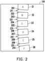
- FIG. 2 is a schematic view of a first image according to an embodiment of the disclosure.
- objects 21 to 26 arranged adjacently to one another may be present in the image 101.
- the objects 21 to 26 may actually be the osteomeres (marked as A to F) of the specific part (such as the neck or back) of the human body.
- the processor 11 may analyze the image 101 to detect endpoints 201 to 210 on the objects 21 to 26.
- the endpoint 201 is the endpoint at a lower left corner of the object 21.
- the endpoint 202 is the endpoint at an upper left corner of the object 22, and the endpoint 203 is the endpoint at a lower left corner of the object 22.
- the endpoint 204 is the endpoint at an upper left corner of the object 23, and the endpoint 205 is the endpoint at a lower left corner of the object 23.
- the endpoint 206 is the endpoint at an upper left corner of the object 24, and the endpoint 207 is the endpoint at a lower left corner of the object 24.
- the endpoint 208 is the endpoint at an upper left corner of the object 25, and the endpoint 209 is the endpoint at a lower left corner of the object 25.
- the endpoint 210 is the endpoint at an upper left corner of the object 26. It should be noted that the endpoints 201 to 210 are all located on the same side of the objects 21 to 26 (for example, the left side).
- the processor 11 may detect central points 211 to 251 between any two of the adjacent endpoints according to positions of the endpoints 201 to 210.
- the central point 211 is located at a central position between the endpoints 201 and 202.
- the central point 221 is located at a central position between the endpoints 203 and 204.
- the central point 231 is located at a central position between the endpoints 205 and 206.
- the central point 241 is located at a central position between the endpoints 207 and 208.
- the central point 251 is located at a central position between the endpoints 209 and 210.
- the processor 11 may detect a distance between any two of the adjacent central points among the central points 211 to 251.
- FIG. 3 is a schematic view of detecting distances between multiple adjacent central points according to an embodiment of the disclosure.
- the processor 11 may obtain distances D(1) to D(4) between any two of the adjacent central points among the central points 211 to251.
- the distance D(1) reflects a linear distance between the central points 211 and 221.
- the distance D(2) reflects a linear distance between the central points 221 and 231.
- the distance D(3) reflects a linear distance between the central points 231 and 241.
- the distance D(4) reflects a linear distance between the central points 241 and 251.
- the processor 11 may determine the target region in the image 101 based on one of the central points 211 to 251 as the center of the target region. In addition, the processor 11 may determine a coverage range of the target region according to at least one of the distances D(1) to D(4). For example, the at least one of the distances D(1) to D(4) may be positively correlated with an area of the coverage range of the target region. For example, if a value of the at least one of the distances D(1) to D(4) is larger, the area of the coverage range of the target region may also be larger.
- the coverage range of the target region may be defined by a length and a width of the target region. Therefore, in an embodiment, the processor 11 may determine the length and/or the width of the target region according to the distance. In addition, if the target region is a circle, the coverage range of the target region may be defined by a radius of the target region. Therefore, in an embodiment, the processor 11 may determine the radius of the target region according to the distance.
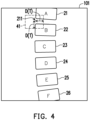
- FIG. 4 is a schematic view of determining a target region in a first image according to an embodiment of the disclosure.
- the processor 11 may determine a target region 41 based on the central point 211 as the center of the target region.
- a center of the target region 41 may be located at a position where the central point 211 is located and/or overlap with the central point 211.
- the processor 11 may also determine the target region 41 based on any one of the central points 221 to 251 as the center of the target region.
- the processor 11 may determine a coverage range of the target region 41 according to the at least one of the distances D(1) to D(4).
- the processor 11 may determine a distance D(T) according to an average value (also referred to as an average distance) of at least two of the distances D(1) to D(4).
- the distance D(T) may be a half of a length and/or a width of the target region 41.
- the distance D(T) may also be a radius of the target region 41.
- the average distance may also be replaced by any one of the distances D(1) to D(4).
- the distance D(T) may also be fine-tuned through a function to slightly enlarge or reduce the distance D(T). In this way, even if a shape of at least one of the objects 21 to 26 is relatively irregular, and/or a size is quite different from the other objects, the fine-tuned distance D(T) may also provide higher operating tolerance for the objects 21 to 26.
- the target region 41 may be determined in the image 101 according to the distance D(T).
- the processor 11 may capture an image located in the target region 41 from the image 101 as the image 102.
- FIG. 5 is a schematic view of a second image according to an embodiment of the disclosure.
- the image 102 captured from the target region 41 may present at least a portion of the object 21 (i.e., the osteomere A) and at least a portion of the object 22 (i.e., the osteomere B).
- the image 102 may present a gap GP between the objects 21 and 22.
- the processor 11 may analyze the image 102 to generate status information that may reflect a status of the gap GP.
- the status information may include the scoring information related to mSASSS or other useful information.
- the processor 11 may filter out an image of at least a portion of endpoints or edges of the objects 21 (and/or 22) that is not located in the target region 41 in the image 101. After filtering out the image of at least the portion of the endpoints or the edges of the objects 21 (and/or 22) that is not located in the target region 41, the remaining image is the image 102, as shown in FIG. 5 .
- the image analyzation module 121 may focus on analyzing an image content related to the gap GP in the image 102 (such as a width and/or a shape of the gap GP, etc.) and generate the corresponding status information.
- the image analyzation module 121 may more accurately generate the status information that may reflect the status of the gap. In this way, an accuracy of automated image analyzation for the X-ray image may be effectively improved.
- FIG. 6 is a flowchart of an image analyzation method according to an embodiment of the disclosure.
- the first image is obtained, and at least the first object and the second object are present in the first image.
- the first image is analyzed to detect the first central point between the first endpoint of the first object and the second endpoint of the second object.
- the target region is determined in the first image based on the first central point as the center of the target region.
- the second image located in the target region is captured from the first image.
- the second image is analyzed to generate the status information, and the status information reflects the gap status between the first object and the second object.
- each of the steps in FIG. 6 has been described in detail as above. Thus, details in this regard will not be further reiterated in the following. It is worth noting that each of the steps in FIG. 6 may be implemented as multiple program codes or circuits, and the disclosure is not limited thereto. In addition, the method in FIG. 6 may be used in conjunction with the above exemplary embodiments, or may be used alone. The disclosure is not limited thereto.
- the information, in the original image (such as the X-ray image), which is irrelevant to the gap between the specific objects (such as the osteomeres) may be filtered out, and only the remaining image content is analyzed. In this way, the accuracy of the automated image analyzation for the image containing multiple objects may be effectively improved.
Landscapes
- Engineering & Computer Science (AREA)
- Physics & Mathematics (AREA)
- General Physics & Mathematics (AREA)
- Theoretical Computer Science (AREA)
- Computer Vision & Pattern Recognition (AREA)
- Geometry (AREA)
- Multimedia (AREA)
- Image Processing (AREA)
- Magnetic Resonance Imaging Apparatus (AREA)
- Optical Fibers, Optical Fiber Cores, And Optical Fiber Bundles (AREA)
- Apparatus For Radiation Diagnosis (AREA)
- Image Analysis (AREA)
Description
- The disclosure relates to an image analyzation technology, and more particularly, to an image analyzation method and an image analyzation device.
- With the advancement of technology, it is becoming more and more common to use automated image analyzation technology to assist professionals such as doctors or laboratory scientists in analyzing medical images.
- NGUYEN THONG PHI ET AL: "Deep learning system for Meyerding classification and segmental motion measurement in diagnosis of lumbar spondylolisthesis", BIOMEDICAL SIGNAL PROCESSING AND CONTROL, ELSEVIER, AMSTERDAM, NL, vol. 65, 28 November 2020 mainly concerns the development of a deep learning system with supported by the convolutional neural network (CNN), in which the supplementary CNN model is trained to re-correct the keypoints located on corners of vertebra based on the first CNN regression model, to precisely measure required characteristics. In order to determine the instability of the lumbar spondylolisthesis, the measurement ability of the proposed method is also required to adapt to multiple lateral bending views including flexion and extension postures.
-
WO 01/55965 A2 - However, the current automated image analyzation technology is not more accurate for the analysis of the X-ray image of human spine. The possible reason is that a general spine X-ray image will present multiple adjacent vertebrae (also referred to as osteomeres). When interpreting the spine X-ray image, it is possible that, in the automated image analyzation technology, too many osteomeres exist in the same spine X-ray image at the same time, so that the system cannot locate the correct osteomere for analysis.
- In order to solve the above problem, the invention provides an image analyzation method according to
claim 1 and an image analyzation device according to claim 6, which may improve an accuracy of automated image analyzation. Advantageous embodiments are the subject of the dependent claims. - An embodiment of the disclosure provides an image analyzation method carried out by an image analyzation device, which includes the following steps. A first image which is an X-ray image is obtained, and at least a first object and a second object are presented in the first image. The first image is analyzed to detect a first central point between a first endpoint of the first object and a second endpoint of the second object. A target region is determined in the first image based on the first central point as a center of the target region. A second image located in the target region is captured from the first image. The second image is analyzed to generate status information, and the status information reflects a gap status between the first object and the second object.
- An embodiment of the disclosure further provides an image analyzation device, which includes a processor and a storage circuit. The processor is coupled to the storage circuit. The processor is coupled to the storage circuit. The processor is configured to: obtain a first image which is an X-ray image, and at least a first object and a second object are presented in the first image; analyze the first image to detect a first central point between a first endpoint of the first object and a second endpoint of the second object; determine a target region in the first image based the first central point as a center of the target region; capture a second image located in the target region from the first image; and analyze the second image to generate status information, and the status information reflects a gap status between the first object and the second object.
- Based on the above, after obtaining the first image, the first central point between the first endpoint of the first object in the first image and the second endpoint of the second object in the first image may be detected, and the target region may be automatically determined in the first image based on the first central point as the center of the target region. Next, the second image located in the target region may be captured from the first image and analyzed to generate the status information. In particular, the status information reflects the gap status between the first object and the second object. In this way, the accuracy of the automated image analyzation may be effectively improved.
-
-
FIG. 1 is a schematic view of an image analyzation device according to an embodiment of the disclosure. -
FIG. 2 is a schematic view of a first image according to an embodiment of the disclosure. -
FIG. 3 is a schematic view of detecting distances between multiple adjacent central points according to an embodiment of the disclosure. -
FIG. 4 is a schematic view of determining a target region in a first image according to an embodiment of the disclosure. -
FIG. 5 is a schematic view of a second image according to an embodiment of the disclosure. -
FIG. 6 is a flowchart of an image analyzation method according to an embodiment of the disclosure. -
FIG. 1 is a schematic view of an image analyzation device according to an embodiment of the disclosure. Referring toFIG. 1 , a device (also referred to as an image analyzation device) 10 may be any electronic device or computer device with image analyzation and calculation functions. In an embodiment, thedevice 10 may also be an X-ray inspection device or an X-ray scanner (referred to as an X-ray machine). - The
device 10 includes aprocessor 11, astorage circuit 12, and an input/output (I/O)device 13. Theprocessor 11 is coupled to thestorage circuit 12 and the I/O device 13. Theprocessor 11 is configured to be responsible for the overall or partial operation of thedevice 10. For example, theprocessor 11 may include a central processing unit (CPU), a graphics processing unit (GPU), other programmable general-purpose or special-purpose microprocessors, a digital signal processor (DSP), a programmable controller, an application specific integrated circuit (ASIC), a programmable logic device PLD), other similar devices, or a combination of the devices. - The
storage circuit 12 is configured to store data. For example, thestorage circuit 12 may include a volatile storage circuit and a non-volatile storage circuit. The volatile storage circuit is configured to store the data volatilely. For example, the volatile storage circuit may include a random access memory (RAM) or similar volatile storage media. The non-volatile storage circuit is configured to store the data non-volatilely. For example, the non-volatile storage circuit may include a read only memory (ROM), a solid state disk (SSD), a traditional hard disk drive (HDD), or similar non-volatile storage media. - In an embodiment, the
storage circuit 12 stores an image analyzation module 121 (also referred to as an image recognition module). Theimage analyzation module 121 may perform an image recognition operation such as machine vision. For example, theprocessor 11 may run theimage analyzation module 121 to automatically recognize a specific object presented in a specific image file. In addition, theimage analyzation module 121 may also be trained to improve a recognition accuracy. In an embodiment, theimage analyzation module 121 may also be implemented as a hardware circuit. For example, theimage analyzation module 121 may be implemented as an independent image processing chip (such as the GPU). In addition, theimage analyzation module 121 may also be disposed inside theprocessor 11. - The I/
O device 13 may include an input/output device of various signals such as a communication interface, a mouse, a keyboard, a screen, a touch screen, a speaker, and/or a microphone. The disclosure does not limit the type of the I/O device 13. - In an embodiment, the
processor 11 may obtain an image (also referred to as a first image) 101. For example, theimage 101 may be stored in thestorage circuit 12. Theimage 101 may be an X-ray image. For example, theimage 101 may be the X-ray image obtained by using the X-ray machine to perform X-ray irradiation or scanning on a specific part of a human body. Multiple objects may be presented in theimage 101. For example, the objects include at least a first object and a second object. - In an embodiment, both the first object and the second object are skeletons of the human body. For example, the first object and the second object may include a vertebra (also referred to as an osteomere) of a neck or a back of the human body. For example, in an embodiment, the
image 101 may be the X-ray image which may present a shape and an arrangement of the osteomeres of the neck or the back of the human body obtained by using the X-ray machine to perform the X-ray irradiation or scanning on the neck or the back of the human body. - In an embodiment, the
processor 11 may analyze theimage 101 through theimage analyzation module 121, so as to detect an endpoint (also referred to as a first endpoint) of the first object and an endpoint (also referred to as a second endpoint) of the second object in theimage 101. Next, theprocessor 11 may detect a central point (also referred to as a first central point) between the first endpoint and the second endpoint. The first central point may be located at a central position between the first endpoint and the second endpoint. - In an embodiment, the
processor 11 may determine a region (also referred to as a target region) in the first image based on the first central point as a center of the target region, and capture an image (also referred to as a second image) 102 located in the target region from the first image. For example, a central position of the target region may be located at a position where the first central point is located and/or overlap with the first central point. For example, a shape of the target region may be a rectangle, a circle, or other shapes. In addition, the capturedimage 102 may also be stored in thestorage circuit 12. - In an embodiment, the
processor 11 may analyze theimage 102 through theimage analyzation module 121 to generate status information. In particular, the status information may reflect a status of a gap (also referred to as a gap status) between the first object and the second object. For example, if the first object and the second object are the two adjacently arranged osteomeres of the neck or the back of the human body, the status information may reflect the status of the gap between the two osteomeres (for example, a width of the gap between the two osteomeres or the closeness of the two osteomeres), a health status of the two osteomeres, whether the arrangement of the two osteomeres conforms to characteristics of a specific disease, and/or whether the gap between the two osteomeres conforms to the characteristics of the specific disease. For example, the specific disease may include ankylosing spondylitis or other diseases. - In an embodiment, the status information may include scoring information. The scoring information may reflect a health status of the human body or a risk of suffering from the specific disease. For example, in an embodiment, the scoring information may include mSASSS. The mSASSS may reflect a risk level of ankylosing spondylitis in the human body corresponding to the image 102 (or 101). In an embodiment, the scoring information may also reflect a risk level of other types of diseases in the human body. The disclosure is not limited thereto.
- In an embodiment, the status information may be presented in a form of a report. For example, the status information may be presented on a display of the
device 10. In an embodiment, the status information may be sent to other devices, such as a smart phone, a tablet computer, a notebook computer, or a desktop computer, so as to be viewed by a user of other devices. -
FIG. 2 is a schematic view of a first image according to an embodiment of the disclosure. Referring toFIG. 2 , in an embodiment, objects 21 to 26 arranged adjacently to one another may be present in theimage 101. For example, theobjects 21 to 26 may actually be the osteomeres (marked as A to F) of the specific part (such as the neck or back) of the human body. In addition, in the presented objects 21 to 26, there is a gap (also referred to as a physical gap) between every two of the adjacently arranged objects. It should be noted that the disclosure does not limit the total number and arrangement status of theobjects 21 to 26 presented in theimage 101. - In an embodiment, the
processor 11 may analyze theimage 101 to detectendpoints 201 to 210 on theobjects 21 to 26. For example, theendpoint 201 is the endpoint at a lower left corner of theobject 21. Theendpoint 202 is the endpoint at an upper left corner of theobject 22, and theendpoint 203 is the endpoint at a lower left corner of theobject 22. Theendpoint 204 is the endpoint at an upper left corner of theobject 23, and theendpoint 205 is the endpoint at a lower left corner of theobject 23. Theendpoint 206 is the endpoint at an upper left corner of theobject 24, and theendpoint 207 is the endpoint at a lower left corner of theobject 24. Theendpoint 208 is the endpoint at an upper left corner of theobject 25, and theendpoint 209 is the endpoint at a lower left corner of theobject 25. Theendpoint 210 is the endpoint at an upper left corner of theobject 26. It should be noted that theendpoints 201 to 210 are all located on the same side of theobjects 21 to 26 (for example, the left side). - After finding the
endpoints 201 to 210, theprocessor 11 may detectcentral points 211 to 251 between any two of the adjacent endpoints according to positions of theendpoints 201 to 210. For example, thecentral point 211 is located at a central position between theendpoints central point 221 is located at a central position between theendpoints central point 231 is located at a central position between theendpoints central point 241 is located at a central position between theendpoints central point 251 is located at a central position between theendpoints central points 211 to 251, theprocessor 11 may detect a distance between any two of the adjacent central points among thecentral points 211 to 251. -
FIG. 3 is a schematic view of detecting distances between multiple adjacent central points according to an embodiment of the disclosure. Referring toFIG. 3 , following the embodiment ofFIG. 2 , theprocessor 11 may obtain distances D(1) to D(4) between any two of the adjacent central points among thecentral points 211 to251. For example, the distance D(1) reflects a linear distance between thecentral points central points central points central points - In an embodiment, the
processor 11 may determine the target region in theimage 101 based on one of thecentral points 211 to 251 as the center of the target region. In addition, theprocessor 11 may determine a coverage range of the target region according to at least one of the distances D(1) to D(4). For example, the at least one of the distances D(1) to D(4) may be positively correlated with an area of the coverage range of the target region. For example, if a value of the at least one of the distances D(1) to D(4) is larger, the area of the coverage range of the target region may also be larger. - In an embodiment, if the target region is a rectangle, the coverage range of the target region may be defined by a length and a width of the target region. Therefore, in an embodiment, the
processor 11 may determine the length and/or the width of the target region according to the distance. In addition, if the target region is a circle, the coverage range of the target region may be defined by a radius of the target region. Therefore, in an embodiment, theprocessor 11 may determine the radius of the target region according to the distance. -
FIG. 4 is a schematic view of determining a target region in a first image according to an embodiment of the disclosure. Referring toFIG. 4 , following the embodiment ofFIG. 3 and taking thecentral point 211 as an example, theprocessor 11 may determine atarget region 41 based on thecentral point 211 as the center of the target region. A center of thetarget region 41 may be located at a position where thecentral point 211 is located and/or overlap with thecentral point 211. In an embodiment, theprocessor 11 may also determine thetarget region 41 based on any one of thecentral points 221 to 251 as the center of the target region. In addition, theprocessor 11 may determine a coverage range of thetarget region 41 according to the at least one of the distances D(1) to D(4). - In an embodiment, the
processor 11 may determine a distance D(T) according to an average value (also referred to as an average distance) of at least two of the distances D(1) to D(4). The distance D(T) may be a half of a length and/or a width of thetarget region 41. In addition, in an embodiment, if thetarget region 41 is a circle, the distance D(T) may also be a radius of thetarget region 41. In an embodiment, the average distance may also be replaced by any one of the distances D(1) to D(4). - In an embodiment, the distance D(T) may also be fine-tuned through a function to slightly enlarge or reduce the distance D(T). In this way, even if a shape of at least one of the
objects 21 to 26 is relatively irregular, and/or a size is quite different from the other objects, the fine-tuned distance D(T) may also provide higher operating tolerance for theobjects 21 to 26. - After the distance D(T) is determined, the
target region 41 may be determined in theimage 101 according to the distance D(T). In addition, after determining thetarget region 41, theprocessor 11 may capture an image located in thetarget region 41 from theimage 101 as theimage 102. -
FIG. 5 is a schematic view of a second image according to an embodiment of the disclosure. Referring toFIG. 5 , following the embodiment ofFIG. 4 , theimage 102 captured from thetarget region 41 may present at least a portion of the object 21 (i.e., the osteomere A) and at least a portion of the object 22 (i.e., the osteomere B). In particular, theimage 102 may present a gap GP between theobjects processor 11 may analyze theimage 102 to generate status information that may reflect a status of the gap GP. For example, the status information may include the scoring information related to mSASSS or other useful information. - In an embodiment, in an operation of capturing the
image 102 from thetarget region 41, theprocessor 11 may filter out an image of at least a portion of endpoints or edges of the objects 21 (and/or 22) that is not located in thetarget region 41 in theimage 101. After filtering out the image of at least the portion of the endpoints or the edges of the objects 21 (and/or 22) that is not located in thetarget region 41, the remaining image is theimage 102, as shown inFIG. 5 . In this way, when theimage 102 is subsequently analyzed by theimage analyzation module 121, theimage analyzation module 121 may focus on analyzing an image content related to the gap GP in the image 102 (such as a width and/or a shape of the gap GP, etc.) and generate the corresponding status information. - Compared with the
image 101 which is analyzed directly in a large scale, information, in theimage 102, which is irrelevant to the gap (such as the gap GP) between the osteomeres to be analyzed and may cause a misjudge of theimage analyzation module 121 is filtered out (for example, a main display content of theimage 102 is located at the gap GP between the twoobjects 21 and 22 (for example, the osteomeres A and B)). Therefore, theimage analyzation module 121 may more accurately generate the status information that may reflect the status of the gap. In this way, an accuracy of automated image analyzation for the X-ray image may be effectively improved. -
FIG. 6 is a flowchart of an image analyzation method according to an embodiment of the disclosure. Referring toFIG. 6 , in step S601, the first image is obtained, and at least the first object and the second object are present in the first image. In step S602, the first image is analyzed to detect the first central point between the first endpoint of the first object and the second endpoint of the second object. In step S603, the target region is determined in the first image based on the first central point as the center of the target region. In step S604, the second image located in the target region is captured from the first image. In step S605, the second image is analyzed to generate the status information, and the status information reflects the gap status between the first object and the second object. - However, each of the steps in
FIG. 6 has been described in detail as above. Thus, details in this regard will not be further reiterated in the following. It is worth noting that each of the steps inFIG. 6 may be implemented as multiple program codes or circuits, and the disclosure is not limited thereto. In addition, the method inFIG. 6 may be used in conjunction with the above exemplary embodiments, or may be used alone. The disclosure is not limited thereto. - Based on the above, in the embodiment of the disclosure, the information, in the original image (such as the X-ray image), which is irrelevant to the gap between the specific objects (such as the osteomeres) may be filtered out, and only the remaining image content is analyzed. In this way, the accuracy of the automated image analyzation for the image containing multiple objects may be effectively improved.
Claims (10)
- An image analyzation method carried out by an image analyzation device (10), comprising:obtaining a first image (101) which is an X-ray image, wherein at least a first object and a second object are presented in the first image (101);characterized byanalyzing the first image (101) to detect a first central point between a first endpoint of the first object and a second endpoint of the second object;determining a target region (41) in the first image (101) based on the first central point as a center of the target region (41);capturing a second image (102) located in the target region (41) from the first image (101); andanalyzing the second image (102) to generate status information, wherein the status information reflects a gap (GP) status between the first object and the second object.
- The image analyzation method according to claim 1, wherein there is a physical gap (GP) between the first object and the second object, and the first endpoint of the first object and the second endpoint of the second object are adjacent to each other through the physical gap (GP).
- The image analyzation method according to claim 1, wherein a third object is further presented in the first image (101), and the image analyzation method further comprises:analyzing the first image (101) to detect a second central point between the second endpoint of the second object and a third endpoint of the third object; anddetermining a coverage range of the target region (41) according to a distance (D(1), D (2), D(3), D(4), D(T)) between the first central point and the second central point.
- The image analyzation method according to claim 3, wherein the distance (D(1), D (2), D(3), D(4), D(T)) between the first central point and the second central point is positively correlated with an area of the coverage range of the target region (41).
- The image analyzation method according to claim 1, wherein capturing the second image (102) located in the target region (41) from the first image (101) comprises:
filtering out an image of at least a portion of endpoints (201, 202, 203, 204, 205, 206, 207, 208, 209, 210) or edges of the first object that is not located in the target region (41) in the first image (101). - An image analyzation device (10), comprising:a storage circuit (12); anda processor (11) coupled to the storage circuit (12),wherein the processor (11) is configured to:
obtain a first image (101) which is an X-ray image, wherein at least a first object and a second object are presented in the first image (101);characterized in that the processor (11) is further configured to:analyze the first image (101) to detect a first central point between a first endpoint of the first object and a second endpoint of the second object;determine a target region (41) in the first image (101) based on the first central point as a center of the target region (41);capture a second image (102) located in the target region (41) from the first image (101); andanalyze the second image (102) to generate status information, wherein the status information reflects a gap status between the first object and the second object. - The image analyzation device (10) according to claim 6, wherein there is a physical gap (GP) between the first object and the second object, and the first endpoint of the first object and the second endpoint of the second object are adjacent to each other through the physical gap (GP).
- The image analyzation device (10) according to claim 6, wherein a third object is further presented in the first image (101), and the processor (11) is further configured to:analyze the first image (101) to detect a second central point between the second endpoint of the second object and a third endpoint of the third object; anddetermine a coverage range of the target region (41) according to a distance (D(1), D (2), D(3), D(4), D(T)) between the first central point and the second central point.
- The image analyzation device (10) according to claim 8, wherein the distance (D(1), D (2), D(3), D(4), D(T)) between the first central point and the second central point is positively correlated with an area of the coverage range of the target region (41).
- The image analyzation device (10) according to claim 6, wherein an operation of capturing the second image (102) located in the target region (41) from the first image (101) comprises:
filtering out an image of at least a portion of endpoints (201, 202, 203, 204, 205, 206, 207, 208, 209, 210) or edges of the first object that is not located in the target region (41) in the first image (101).
Applications Claiming Priority (1)
| Application Number | Priority Date | Filing Date | Title |
|---|---|---|---|
| TW110116847A TWI806047B (en) | 2021-05-11 | 2021-05-11 | Image analyzation method and image analyzation device |
Publications (2)
| Publication Number | Publication Date |
|---|---|
| EP4089635A1 EP4089635A1 (en) | 2022-11-16 |
| EP4089635B1 true EP4089635B1 (en) | 2025-03-05 |
Family
ID=78332635
Family Applications (1)
| Application Number | Title | Priority Date | Filing Date |
|---|---|---|---|
| EP21203697.4A Active EP4089635B1 (en) | 2021-05-11 | 2021-10-20 | Image analyzation method and image analyzation device |
Country Status (3)
| Country | Link |
|---|---|
| US (1) | US20220366592A1 (en) |
| EP (1) | EP4089635B1 (en) |
| TW (1) | TWI806047B (en) |
Family Cites Families (12)
| Publication number | Priority date | Publication date | Assignee | Title |
|---|---|---|---|---|
| EP1188148A2 (en) * | 2000-01-27 | 2002-03-20 | Koninklijke Philips Electronics N.V. | Method and system for extracting spine geometrical data |
| KR101347916B1 (en) * | 2006-06-28 | 2014-02-06 | 헥터 오. 파체코 | Templating and placing artifical discs in spine |
| DE102007007803B4 (en) * | 2007-02-16 | 2015-03-26 | Siemens Aktiengesellschaft | Method for automatic evaluation of tomographic image data sets, tomography system and computer workstation |
| US8676298B2 (en) * | 2010-08-30 | 2014-03-18 | Fujifilm Corporation | Medical image alignment apparatus, method, and program |
| CN108053400B (en) * | 2017-12-21 | 2021-06-15 | 上海联影医疗科技股份有限公司 | Image processing method and device |
| TWI684994B (en) * | 2018-06-22 | 2020-02-11 | 國立臺灣科技大學 | Spline image registration method |
| US11819424B2 (en) * | 2018-09-24 | 2023-11-21 | Simplify Medical Pty Ltd | Robot assisted intervertebral disc prosthesis selection and implantation system |
| CN110569854B (en) * | 2019-09-12 | 2022-03-29 | 上海商汤智能科技有限公司 | Image processing method and device, electronic equipment and storage medium |
| CN111340800B (en) * | 2020-03-18 | 2024-02-27 | 联影智能医疗科技(北京)有限公司 | Image detection method, computer device, and storage medium |
| US11205085B1 (en) * | 2020-07-29 | 2021-12-21 | GE Precision Healthcare LLC | Systems and methods for intensity guided interactive measurement |
| CN112184623B (en) * | 2020-09-01 | 2024-12-24 | 联影智能医疗科技(北京)有限公司 | Method, device and storage medium for analyzing intervertebral disc space of spinal vertebra |
| US12217442B2 (en) * | 2021-02-10 | 2025-02-04 | Medtronic Navigation, Inc. | Systems and methods for registration between patient space and image space using registration frame apertures |
-
2021
- 2021-05-11 TW TW110116847A patent/TWI806047B/en active
- 2021-09-30 US US17/491,521 patent/US20220366592A1/en not_active Abandoned
- 2021-10-20 EP EP21203697.4A patent/EP4089635B1/en active Active
Also Published As
| Publication number | Publication date |
|---|---|
| TWI806047B (en) | 2023-06-21 |
| EP4089635A1 (en) | 2022-11-16 |
| US20220366592A1 (en) | 2022-11-17 |
| TW202244845A (en) | 2022-11-16 |
Similar Documents
| Publication | Publication Date | Title |
|---|---|---|
| JP7714617B2 (en) | Automated information extraction and refinement in pathology reports using natural language processing | |
| US20210174505A1 (en) | Method and system for imaging and analysis of anatomical features | |
| US9721137B2 (en) | Method and apparatus for fingerprint image reconstruction | |
| JP4883185B2 (en) | Biological information reading device, biological information reading method, and biological information reading program | |
| US10991094B2 (en) | Method of analyzing dental image for correction diagnosis and apparatus using the same | |
| US8229184B2 (en) | Method and algorithm for accurate finger motion tracking | |
| EP2639743A2 (en) | Image processing device, image processing program, and image processing method | |
| US20200178930A1 (en) | Method and system for evaluating cardiac status, electronic device and ultrasonic scanning device | |
| CN108109170B (en) | Medical image scanning method and medical imaging equipment | |
| US11669193B2 (en) | Position detection circuit and position detection method | |
| CN110910348B (en) | Method, device, equipment and storage medium for classifying positions of pulmonary nodules | |
| JP5640280B2 (en) | Osteoporosis diagnosis support device and osteoporosis diagnosis support program | |
| CN112184623B (en) | Method, device and storage medium for analyzing intervertebral disc space of spinal vertebra | |
| JP2011118466A (en) | Difference noise replacement device, difference noise replacement method, difference noise replacement program, computer readable recording medium, and electronic equipment with difference noise replacement device | |
| US9928451B2 (en) | Information processing apparatus, controlling method, and computer-readable storage medium | |
| EP4089635A1 (en) | Image analyzation method and image analyzation device | |
| CN113592768A (en) | Rib fracture detection method, rib fracture detection information display method and system | |
| WO2025236453A1 (en) | Cervical lesion related examination result analysis method and apparatus, device, and medium | |
| TWI809343B (en) | Image content extraction method and image content extraction device | |
| CN120048497A (en) | Method, system, electronic equipment and storage medium for reading medical examination sheets | |
| Bindu et al. | Integrating Biometric Systems with Clinical Dermatoglyphics: An Automated Approach to atd Angle Measurement for Disease Screening | |
| CN120213102A (en) | A waveform parameter detection method and device for a multi-parameter monitor | |
| US20200250414A1 (en) | Electronic device and handwriting board system | |
| CN111374710A (en) | Cardiac state assessment method and system, electronic device and ultrasound scanning device | |
| JPH0478966A (en) | Image processing method |
Legal Events
| Date | Code | Title | Description |
|---|---|---|---|
| PUAI | Public reference made under article 153(3) epc to a published international application that has entered the european phase |
Free format text: ORIGINAL CODE: 0009012 |
|
| STAA | Information on the status of an ep patent application or granted ep patent |
Free format text: STATUS: REQUEST FOR EXAMINATION WAS MADE |
|
| 17P | Request for examination filed |
Effective date: 20220912 |
|
| AK | Designated contracting states |
Kind code of ref document: A1 Designated state(s): AL AT BE BG CH CY CZ DE DK EE ES FI FR GB GR HR HU IE IS IT LI LT LU LV MC MK MT NL NO PL PT RO RS SE SI SK SM TR |
|
| GRAP | Despatch of communication of intention to grant a patent |
Free format text: ORIGINAL CODE: EPIDOSNIGR1 |
|
| STAA | Information on the status of an ep patent application or granted ep patent |
Free format text: STATUS: GRANT OF PATENT IS INTENDED |
|
| RIC1 | Information provided on ipc code assigned before grant |
Ipc: G06T 7/62 20170101ALI20240827BHEP Ipc: G06T 7/12 20170101AFI20240827BHEP |
|
| INTG | Intention to grant announced |
Effective date: 20240926 |
|
| GRAS | Grant fee paid |
Free format text: ORIGINAL CODE: EPIDOSNIGR3 |
|
| GRAA | (expected) grant |
Free format text: ORIGINAL CODE: 0009210 |
|
| STAA | Information on the status of an ep patent application or granted ep patent |
Free format text: STATUS: THE PATENT HAS BEEN GRANTED |
|
| AK | Designated contracting states |
Kind code of ref document: B1 Designated state(s): AL AT BE BG CH CY CZ DE DK EE ES FI FR GB GR HR HU IE IS IT LI LT LU LV MC MK MT NL NO PL PT RO RS SE SI SK SM TR |
|
| REG | Reference to a national code |
Ref country code: GB Ref legal event code: FG4D |
|
| REG | Reference to a national code |
Ref country code: CH Ref legal event code: EP |
|
| REG | Reference to a national code |
Ref country code: IE Ref legal event code: FG4D |
|
| REG | Reference to a national code |
Ref country code: DE Ref legal event code: R096 Ref document number: 602021027071 Country of ref document: DE |
|
| PG25 | Lapsed in a contracting state [announced via postgrant information from national office to epo] |
Ref country code: RS Free format text: LAPSE BECAUSE OF FAILURE TO SUBMIT A TRANSLATION OF THE DESCRIPTION OR TO PAY THE FEE WITHIN THE PRESCRIBED TIME-LIMIT Effective date: 20250605 |
|
| PG25 | Lapsed in a contracting state [announced via postgrant information from national office to epo] |
Ref country code: FI Free format text: LAPSE BECAUSE OF FAILURE TO SUBMIT A TRANSLATION OF THE DESCRIPTION OR TO PAY THE FEE WITHIN THE PRESCRIBED TIME-LIMIT Effective date: 20250305 |
|
| REG | Reference to a national code |
Ref country code: NL Ref legal event code: MP Effective date: 20250305 |
|
| PG25 | Lapsed in a contracting state [announced via postgrant information from national office to epo] |
Ref country code: ES Free format text: LAPSE BECAUSE OF FAILURE TO SUBMIT A TRANSLATION OF THE DESCRIPTION OR TO PAY THE FEE WITHIN THE PRESCRIBED TIME-LIMIT Effective date: 20250305 |
|
| REG | Reference to a national code |
Ref country code: LT Ref legal event code: MG9D |
|
| PG25 | Lapsed in a contracting state [announced via postgrant information from national office to epo] |
Ref country code: NO Free format text: LAPSE BECAUSE OF FAILURE TO SUBMIT A TRANSLATION OF THE DESCRIPTION OR TO PAY THE FEE WITHIN THE PRESCRIBED TIME-LIMIT Effective date: 20250605 |
|
| PG25 | Lapsed in a contracting state [announced via postgrant information from national office to epo] |
Ref country code: HR Free format text: LAPSE BECAUSE OF FAILURE TO SUBMIT A TRANSLATION OF THE DESCRIPTION OR TO PAY THE FEE WITHIN THE PRESCRIBED TIME-LIMIT Effective date: 20250305 |
|
| PG25 | Lapsed in a contracting state [announced via postgrant information from national office to epo] |
Ref country code: LV Free format text: LAPSE BECAUSE OF FAILURE TO SUBMIT A TRANSLATION OF THE DESCRIPTION OR TO PAY THE FEE WITHIN THE PRESCRIBED TIME-LIMIT Effective date: 20250305 |
|
| PG25 | Lapsed in a contracting state [announced via postgrant information from national office to epo] |
Ref country code: GR Free format text: LAPSE BECAUSE OF FAILURE TO SUBMIT A TRANSLATION OF THE DESCRIPTION OR TO PAY THE FEE WITHIN THE PRESCRIBED TIME-LIMIT Effective date: 20250606 Ref country code: BG Free format text: LAPSE BECAUSE OF FAILURE TO SUBMIT A TRANSLATION OF THE DESCRIPTION OR TO PAY THE FEE WITHIN THE PRESCRIBED TIME-LIMIT Effective date: 20250305 |
|
| REG | Reference to a national code |
Ref country code: AT Ref legal event code: MK05 Ref document number: 1773643 Country of ref document: AT Kind code of ref document: T Effective date: 20250305 |
|
| PG25 | Lapsed in a contracting state [announced via postgrant information from national office to epo] |
Ref country code: NL Free format text: LAPSE BECAUSE OF FAILURE TO SUBMIT A TRANSLATION OF THE DESCRIPTION OR TO PAY THE FEE WITHIN THE PRESCRIBED TIME-LIMIT Effective date: 20250305 |
|
| PG25 | Lapsed in a contracting state [announced via postgrant information from national office to epo] |
Ref country code: SE Free format text: LAPSE BECAUSE OF FAILURE TO SUBMIT A TRANSLATION OF THE DESCRIPTION OR TO PAY THE FEE WITHIN THE PRESCRIBED TIME-LIMIT Effective date: 20250305 |
|
| PG25 | Lapsed in a contracting state [announced via postgrant information from national office to epo] |
Ref country code: SM Free format text: LAPSE BECAUSE OF FAILURE TO SUBMIT A TRANSLATION OF THE DESCRIPTION OR TO PAY THE FEE WITHIN THE PRESCRIBED TIME-LIMIT Effective date: 20250305 |
|
| PG25 | Lapsed in a contracting state [announced via postgrant information from national office to epo] |
Ref country code: PT Free format text: LAPSE BECAUSE OF FAILURE TO SUBMIT A TRANSLATION OF THE DESCRIPTION OR TO PAY THE FEE WITHIN THE PRESCRIBED TIME-LIMIT Effective date: 20250707 |
|
| PG25 | Lapsed in a contracting state [announced via postgrant information from national office to epo] |
Ref country code: PL Free format text: LAPSE BECAUSE OF FAILURE TO SUBMIT A TRANSLATION OF THE DESCRIPTION OR TO PAY THE FEE WITHIN THE PRESCRIBED TIME-LIMIT Effective date: 20250305 Ref country code: IT Free format text: LAPSE BECAUSE OF FAILURE TO SUBMIT A TRANSLATION OF THE DESCRIPTION OR TO PAY THE FEE WITHIN THE PRESCRIBED TIME-LIMIT Effective date: 20250305 |
|
| PGFP | Annual fee paid to national office [announced via postgrant information from national office to epo] |
Ref country code: GB Payment date: 20250911 Year of fee payment: 5 |
|
| PG25 | Lapsed in a contracting state [announced via postgrant information from national office to epo] |
Ref country code: AT Free format text: LAPSE BECAUSE OF FAILURE TO SUBMIT A TRANSLATION OF THE DESCRIPTION OR TO PAY THE FEE WITHIN THE PRESCRIBED TIME-LIMIT Effective date: 20250305 |
|
| PGFP | Annual fee paid to national office [announced via postgrant information from national office to epo] |
Ref country code: FR Payment date: 20250922 Year of fee payment: 5 |
|
| PG25 | Lapsed in a contracting state [announced via postgrant information from national office to epo] |
Ref country code: CZ Free format text: LAPSE BECAUSE OF FAILURE TO SUBMIT A TRANSLATION OF THE DESCRIPTION OR TO PAY THE FEE WITHIN THE PRESCRIBED TIME-LIMIT Effective date: 20250305 Ref country code: EE Free format text: LAPSE BECAUSE OF FAILURE TO SUBMIT A TRANSLATION OF THE DESCRIPTION OR TO PAY THE FEE WITHIN THE PRESCRIBED TIME-LIMIT Effective date: 20250305 |
|
| PG25 | Lapsed in a contracting state [announced via postgrant information from national office to epo] |
Ref country code: RO Free format text: LAPSE BECAUSE OF FAILURE TO SUBMIT A TRANSLATION OF THE DESCRIPTION OR TO PAY THE FEE WITHIN THE PRESCRIBED TIME-LIMIT Effective date: 20250305 |
|
| PG25 | Lapsed in a contracting state [announced via postgrant information from national office to epo] |
Ref country code: SK Free format text: LAPSE BECAUSE OF FAILURE TO SUBMIT A TRANSLATION OF THE DESCRIPTION OR TO PAY THE FEE WITHIN THE PRESCRIBED TIME-LIMIT Effective date: 20250305 |
|
| PG25 | Lapsed in a contracting state [announced via postgrant information from national office to epo] |
Ref country code: IS Free format text: LAPSE BECAUSE OF FAILURE TO SUBMIT A TRANSLATION OF THE DESCRIPTION OR TO PAY THE FEE WITHIN THE PRESCRIBED TIME-LIMIT Effective date: 20250705 |
|
| REG | Reference to a national code |
Ref country code: DE Ref legal event code: R097 Ref document number: 602021027071 Country of ref document: DE |
|
| PGFP | Annual fee paid to national office [announced via postgrant information from national office to epo] |
Ref country code: DE Payment date: 20250910 Year of fee payment: 5 |
|
| PLBE | No opposition filed within time limit |
Free format text: ORIGINAL CODE: 0009261 |
|
| STAA | Information on the status of an ep patent application or granted ep patent |
Free format text: STATUS: NO OPPOSITION FILED WITHIN TIME LIMIT |
|
| PG25 | Lapsed in a contracting state [announced via postgrant information from national office to epo] |
Ref country code: DK Free format text: LAPSE BECAUSE OF FAILURE TO SUBMIT A TRANSLATION OF THE DESCRIPTION OR TO PAY THE FEE WITHIN THE PRESCRIBED TIME-LIMIT Effective date: 20250305 |
|
| REG | Reference to a national code |
Ref country code: CH Ref legal event code: L10 Free format text: ST27 STATUS EVENT CODE: U-0-0-L10-L00 (AS PROVIDED BY THE NATIONAL OFFICE) Effective date: 20260114 |
|
| 26N | No opposition filed |
Effective date: 20251208 |