EP4089412A1 - Observation holder, observation device, observation chip, and manufacturing method therefor - Google Patents
Observation holder, observation device, observation chip, and manufacturing method therefor Download PDFInfo
- Publication number
- EP4089412A1 EP4089412A1 EP20927398.6A EP20927398A EP4089412A1 EP 4089412 A1 EP4089412 A1 EP 4089412A1 EP 20927398 A EP20927398 A EP 20927398A EP 4089412 A1 EP4089412 A1 EP 4089412A1
- Authority
- EP
- European Patent Office
- Prior art keywords
- observation
- holes
- accommodation unit
- plate
- main body
- Prior art date
- Legal status (The legal status is an assumption and is not a legal conclusion. Google has not performed a legal analysis and makes no representation as to the accuracy of the status listed.)
- Pending
Links
Images


Classifications
-
- G—PHYSICS
- G02—OPTICS
- G02B—OPTICAL ELEMENTS, SYSTEMS OR APPARATUS
- G02B21/00—Microscopes
- G02B21/24—Base structure
- G02B21/26—Stages; Adjusting means therefor
-
- G—PHYSICS
- G02—OPTICS
- G02B—OPTICAL ELEMENTS, SYSTEMS OR APPARATUS
- G02B21/00—Microscopes
- G02B21/24—Base structure
-
- G—PHYSICS
- G02—OPTICS
- G02B—OPTICAL ELEMENTS, SYSTEMS OR APPARATUS
- G02B21/00—Microscopes
- G02B21/0004—Microscopes specially adapted for specific applications
- G02B21/0088—Inverse microscopes
-
- G—PHYSICS
- G02—OPTICS
- G02B—OPTICAL ELEMENTS, SYSTEMS OR APPARATUS
- G02B21/00—Microscopes
- G02B21/34—Microscope slides, e.g. mounting specimens on microscope slides
-
- G—PHYSICS
- G01—MEASURING; TESTING
- G01N—INVESTIGATING OR ANALYSING MATERIALS BY DETERMINING THEIR CHEMICAL OR PHYSICAL PROPERTIES
- G01N33/00—Investigating or analysing materials by specific methods not covered by groups G01N1/00 - G01N31/00
- G01N33/48—Biological material, e.g. blood, urine; Haemocytometers
- G01N33/483—Physical analysis of biological material
-
- G—PHYSICS
- G02—OPTICS
- G02B—OPTICAL ELEMENTS, SYSTEMS OR APPARATUS
- G02B21/00—Microscopes
- G02B21/36—Microscopes arranged for photographic purposes or projection purposes or digital imaging or video purposes including associated control and data processing arrangements
Definitions
- the present invention relates to an observation holder (mainly a cell observation holder).
- PTL 1 and PTL 2 describe the structure of an observation holder for accommodating an observation target such that the target is observable.
- the observation holder is so configured that a cell as an observation target can be observed from below the observation holder.
- a user such as a medical doctor, a laboratory technician, or a researcher can observe an observation target by an image via a predetermined observation instrument (for example, a microscope or an imaging camera).
- observation target examples include a tissue or a body fluid itself as a constituent element of a cell of an animal including a human, for example, a blood or a lymph of a human or a mouse, an ascites and a peritoneal lavage fluid, a bronchoalveolar lavage fluid, various white blood cells and other cells as components thereof, and a cancer cell separated from a tissue and an established cultured cell; and a separated plant cell including a microorganism such as a fungus.
- An observation holder that allows a user to simultaneously observe a plurality of different functions of a cell as an observation target by using an image can be used in, for example, a mass screening test for a newborn baby and diagnoses of various diseases (PTL 3).
- observation holder It is necessary to further improve the structure of the above-described observation holder to make it possible to simply and efficiently observe a plurality of different characteristics and a plurality of different functions of many cells as observation targets at once, and to simultaneously perform these observations and measurements on many samples, for example, many patient samples at once.
- the observation holder is an observation holder including an accommodation unit having a rectangular shape in a planar view and configured to accommodate an observation target, and an observation unit formed below the accommodation unit, characterized in that the observation unit is configured such that an observation target accommodated in the accommodation unit can be observed from below,
- the accommodation unit includes an accommodation unit main body in which a plurality of holes for accommodating an observation target are formed to be spaced apart from each other, and an accommodation unit upper portion formed on an upper portion of the accommodation unit main body, the accommodation unit upper portion includes a wall surrounding a space above the accommodation unit main body, as a storage for storing a predetermined liquid, an opening is formed above the space in the accommodation unit upper portion, and the plurality of holes are arrayed in a horizontal direction, each hole vertically extends through the accommodation unit main body and communicates with the opening, and two adjacent holes of the plurality of holes are connected in the observation unit.
- Fig. 1 is a schematic side view showing an observation apparatus 1 according to an embodiment
- Fig. 2 is a perspective view showing a part of the observation apparatus 1.
- the observation apparatus 1 includes a support base 11, an imaging unit 12, and a moving mechanism 13, and also includes an observation preparation unit 14.
- an observation holder 2 (to be described later) not included in the observation apparatus 1 is mounted on the support base 11.
- the support base 11 is a plate-like member having a predetermined thickness.
- the support base 11 can support a plurality of observation holders 2, and the plurality of observation holders 2 are arranged in a horizontal direction on the support table 11.
- the horizontal direction herein mentioned is a given direction parallel to the upper surface of the support base 11 in a horizontal posture.
- each observation holder 2 can accommodate a predetermined observation target.
- An example of the observation target is a white blood cell of an animal such as a human blood.
- an X direction indicates one of the array directions of the plurality of observation holders 2
- a Y direction indicates the other direction (a direction perpendicular to the X direction) of the array directions.
- a Z direction indicates a vertical direction or an up-down direction.
- each recesses 111 are formed in the support base 11 at equal intervals in the X direction, and are arranged in two rows in the Y direction.
- the observation holder 2 can be mounted as it is fitted in each recess 111.
- an opening 112 extending in the vertical direction is formed in a bottom 111a of each recess 111 so that the mounted observation holder 2 can be viewed from below.
- the bottom 111a of the recess 111 forms the opening 112, and also forms a mounting portion 111b by extending into the form of a flange toward the center from the edges of the opening 112 so that the observation holder 2 can be mounted.
- the observation holder 2 is mounted by abutting a plate (second plate) 222 of an observation unit 22 (to be described later) of the observation holder 2 against the mounting portion 111b.
- the side walls of the recess 111 form a surrounding wall (guide wall) 111c for regulating the movement of the observation holder 2 in the horizontal direction when the observation holder 2 is fitted.
- the surrounding wall 111c is set to be higher than a main body lower portion 210L of a main body 210 (to be described later) of the observation holder 2, and lower than a main body upper portion of the main body 210.
- the imaging unit 12 can capture an image of an observation target accommodated in the observation holder 2, and is installed below the support base 11 in this embodiment.
- the imaging unit 12 it is possible to use a device capable of capturing a moving image and/or a still image, for example, a well-known camera including a CCD/CMOS image sensor or the like. Note that in the following explanation, imaging by the imaging unit 12 can also be expressed as observation.
- the moving mechanism 13 can horizontally move the imaging unit 12 relative to the support base 11, and the moving direction is practically parallel to the X direction in this embodiment.
- the imaging unit 12 is moved to face each of the plurality of openings 112 formed along the X direction.
- the moving mechanism 13 it is possible to use a well-known slider mechanism, for example, a rail 131 slidably supporting the imaging unit 12 in the X direction, a nut (not shown) included in the imaging unit 12, a ball screw formed parallel to the rail 131 and rotatably supported by being engaged with the nut, and an electric motor 132 for rotating the ball screw.
- the plurality of observation holders 2 include two rows arranged in the Y direction of the six recesses 111 arranged in the X direction, that is, include a total of twelve recesses 111.
- the moving mechanism 13 can move the imaging unit 12 in the X direction and the Y direction. Alternatively, it is also possible to move the imaging unit 12 in only the X direction by the moving mechanism 13, and install two sets of a combination of the moving mechanism 13 and the imaging unit 12 in the Y direction.
- the imaging unit 12 are a vision camera, an objective lens, and another imaging device. When using an objective lens as the imaging unit 12, it is possible to form the imaging unit 12 as an index table, set a plurality of objective lenses having different magnifications on the index table, and select an objective lens having a given magnification by index rotation.
- the observation preparation unit 14 is a unit for a user to perform a preparation work.
- the observation preparation unit 14 includes a preparation support base 141 and a moving mechanism (second moving mechanism) 142.
- the preparation support base 141 can support the observation holder 2 in a state (unaccommodated state) in which no observation target is accommodated.
- a recess 111 and an opening 112 are formed in the preparation support base 141 like those of the support base 11.
- the user can make preparations for observation by accommodating an observation target in the observation holder 2 supported by the preparation support base 141, by injecting the observation target by using a predetermined instrument or device, for example, a manual injector such as a syringe or a dropper, or an automatic injector such as a vertical 6-axis robot or a SCARA robot.
- a predetermined instrument or device for example, a manual injector such as a syringe or a dropper, or an automatic injector such as a vertical 6-axis robot or a SCARA robot.
- workers such as a medical doctor, a laboratory technician, and a researcher can be taken as typical examples of the user, but the user can also be an industrial robot or a manipulator that operates based on instructions from one or more of these workers.
- the moving mechanism 142 can move the preparation support base 141 in a predetermined direction (at least the Z direction).
- a predetermined direction at least the Z direction.
- the height of the preparation support base 141 can be adjusted by operating the moving mechanism 142, thereby making preparations for observation.
- the moving mechanism 142 it is possible to use a well-known slider mechanism, for example, a rail 1421 for slidably supporting the preparation support base 141, and an electric motor 1422 for sliding the preparation support base 141 along the rail 1421.
- the user injects an observation target into the observation holder 2 supported by the preparation support base 141, thereby making preparations for observation. After that, the user transfers the observation holder 2 from the preparation support table 141 to the support table 11, thereby completing the setting of the observation holder 2 with respect to the observation apparatus 1. Then, the user observes the observation target from below the observation holder 2 by using the imaging unit 12.
- the preparations of the observation target are to make it possible to cause the imaging unit 12 to capture an image of the observation unit 22 (to be described later) of the observation holder 2 from below, and inject the observation target into a predetermined position (observation position) of the observation holder 2 while checking the captured image, thereby placing a cell as the observation target in the observation position.
- the observation apparatus 1 can also be called an observation system, an evaluation apparatus, an evaluation system, a diagnostic apparatus, a diagnostic system, or the like.
- Fig. 3 shows a perspective view of the observation holder 2.
- Fig. 4 shows an exploded view of the observation holder 2.
- the observation holder 2 includes an accommodation unit 21 and the observation unit 22. Note that Figs. 3 and 4 depict the X, Y, and Z directions corresponding to those shown in Fig. 2 .
- the accommodation unit 21 has a rectangular shape, that is, an oblong shape in this embodiment in a planar view (a view point in the Z direction, a top view), and can accommodate the observation target described above.
- the accommodation unit 21 includes an accommodation unit main body 210 and an accommodation unit upper portion 211.
- the accommodation unit main body 210 has a projection 2101 in the central portion along a lateral direction (the Y direction in Fig. 3 ) in a planar view.
- the projection 2101 is extended in a longitudinal direction (the X direction in Fig. 3 ) in a planar view.
- step surfaces 2102 are formed on the both sides of the projection 2101.
- a plurality of holes H1 for accommodating an observation target are formed to be spaced apart from each other in the projection 2101 of the accommodation unit main body 210.
- the plurality of holes H1 are arrayed in the X direction and the Y direction, and each hole H1 is so formed as to extend through the projection 2101 in the Z direction.
- a hydrophilic treatment can be performed on each surface of the plurality of holes H1 formed in the accommodation unit main body 210 and brought into contact with a liquid.
- An upper surface 210U of the projection 2101 is planarized, and each hole H1 has an opening end in the upper surface 210U. That region of the upper surface 210U, which includes the holes H1 and their surroundings, is a flat region 210R (see Fig. 3 ).
- the accommodation unit upper portion 211 is formed on the upper portion of the accommodation unit main body 210, and has an opening 2112 for forming a space above the flat region 210R of the accommodation unit main body 210 when the accommodation unit upper portion 211 is set on the accommodation unit main body 210.
- the space surrounded by walls 2111a in the accommodation unit upper portion 211 is the opening 2112.
- the opening 2112 is formed to extend through the accommodation unit upper portion 211, and has different opening areas in the upper and lower portions of the accommodation unit upper portion 211.
- a lower opening 2112b is a portion into which the projection 210 is inserted, and is formed to have almost the same size as that of the shape of the projection 210.
- an upper opening 2112a is a portion that forms a space above the flat region 210R, and is formed to have almost the same size as that of the shape of the flat region 210R. That is, the opening area of the upper opening 2112a is smaller than that of the lower opening 2112b.
- a portion of the upper surface 210U of the projection 210 engages with a step surface SS between the upper opening 2112a and the lower opening 2112b, and as a consequence the flat region 210R faces the upper opening 2112a.
- a portion of a lower portion 211L of the accommodation unit upper portion 211 engages with the step surface 2102 of the accommodation unit main body 210.
- the space surrounded by the upper opening 2112a and the flat region 210R functions as a storage for storing a predetermined liquid.
- an uppermost portion 2112c of the opening 2112 is formed to increase in a tapered shape.
- the opening 2112 has different sectional areas in the upper and lower portions of the accommodation unit upper portion 211, and the storage volume is decreased by forming the storage in the upper opening 2112a having a small sectional area. This makes it possible to decrease the amount of a liquid to be stored in the storage. Also, a hydrophilic treatment like that performed on the surfaces forming the plurality of holes H1 can be performed on the surfaces formed as the storage in the accommodation unit upper portion 211 and brought into contact with a stored liquid. As the liquid, a liquid culture medium corresponding to an observation target can be used, but it is also possible to use other solutions such as a normal saline solution.
- the plurality of holes H1 formed in the accommodation unit main body 210 are not used independently of each other, but used as a U-shaped path by pairing adjacent holes H1 two by two and connecting the lower ends of the holes H1 in the observation unit 22.
- the accommodation unit main body 210 is made of a non-translucent material.
- the accommodation unit upper portion 211 is made of a translucent material.
- non-translucent means that the transmittance of visible light is relatively low.
- the transmittance is 50% or less, preferably 30% or less, and more preferably 10% or less.
- translucent means that the transmittance of visible light is relatively high.
- the transmittance is 50% or more, preferably 70% or more, and more preferably 90% or more.
- the accommodation unit upper portion 211 can also be made of a non-translucent material.
- each of the accommodation unit main body 210 and the accommodation unit upper portion 211 can be formed by one member, and, when each of them is formed by one member, both of them are preferably made of a non-translucent material.
- the observation unit 22 is formed below the accommodation unit 21, and so configured that an observation target accommodated in the accommodation unit 21 can be observed from below by using the imaging unit 12.
- the observation unit 22 includes a plate (first plate) 221 and a plate (second plate) 222.
- the plate 221 covers the accommodation unit main body 210 from below, and the plate 222 covers the plate 221 from below.
- the plate 222 covers the plate 221 from below and is made of a practically translucent material.
- the plate 221 is partially made of a translucent material in this embodiment, but can also be entirely made of a non-translucent material or a reflective material. It is also possible to use a material having a dark-color (for example, black) surface.
- the plate 221 it is possible to use, for example, a silicon disk (silicon wafer) microfabricated by anisotropic dry etching (inductively coupled plasma-reactive ion etching).
- a silicon disk silicon wafer
- anisotropic dry etching inductively coupled plasma-reactive ion etching
- rectangular members having the same size in a planar view are used as the plates 221 and 222.
- At least one of the plates 221 and 222 can be formed such that the abovementioned two adjacent holes H1 communicate with each other. This will be described below with reference to Fig. 5 .
- Fig. 5 is a perspective view of the plate 221.
- a plurality of through holes H3 corresponding to the plurality of holes H1 are formed in the plate 221.
- a cavity CC1 for connecting two adjacent holes (for example, H3a and H3b) of the plurality of through holes H3 is formed in the lower surface of the plate 221.
- the cavity CC1 is formed such that its outer edge surrounds the two through holes H3. That is, on the upper surface side of the plate 221, the plurality of through holes H3 are formed independently of each other in positions corresponding to the plurality of holes H1. On the lower surface side of the plate 221, however, the plurality of through holes H3 are partially not independent of each other because the two adjacent holes H3 communicate with each other by the cavity CC1.
- the cavity CC1 is formed into an elliptical shape in a planar view.
- the cavity CC1 can also be called a terrace, a recess, or the like.
- the cavity CC1 includes a flat portion PL between the two adjacent through holes H3.
- the flat portion PL includes a flat surface PL1.
- the outer edge of the cavity CC1 is formed by side walls WP.
- the side walls WP include circumferential wall portions WP1 and WP2, and two wall portions WP3.
- the circumferential wall portions WP1 and WP2 correspond to the circumferential portions of the ellipse
- the circumferential wall portions WP3 correspond to straight portions of the ellipse.
- the circumferential wall portion WP1 faces one (in this case, H3a) of the two through holes H3, and the circumferential wall portion WP2 faces the other (in this case, H3b) of the two through holes H3.
- the circumferential wall portion WP1 includes a cylindrical upper circumferential wall portion WP1U formed to have the same size as that of the through hole H3, and a semi-cylindrical lower circumferential wall portion WP1L formed to be continuous to the upper circumferential wall portion WP1U and to have the same size as that of the upper circumferential wall portion WP1U.
- the circumferential wall portion WP2 includes a cylindrical upper circumferential wall portion WP2U formed to have the same size as that of the through hole H3, and a semi-cylindrical lower circumferential wall portion WP2L formed to be continuous to the upper circumferential wall portion WP2U and to have the same size as that of the upper circumferential wall portion WP2U.
- the two circumferential wall portions WP3 are so formed as to form continuous surfaces connecting to the circumferential wall portions WP1 and WP2. More specifically, the circumferential wall portions WP3 are formed as continuous surfaces that connect the lower circumferential wall portion WP1L of the circumferential wall portion WP1 to the lower circumferential wall portion WP2L of the circumferential wall portion WP2, which is formed to correspond to the lower circumferential wall portion WP1L of the circumferential wall portion WP1, and that have the same height as that of the lower circumferential wall portions WP1L and WP2L.
- each through hole H3 is formed into an almost circular shape in a planar view
- each of the upper circumferential wall portions WP1U and WP2U of the circumferential wall portions WP1 and WP2 is formed to draw a circle having the same diameter as that of the through hole H3
- each of the lower circumferential wall portions WP1L and WP2L of the circumferential wall portions WP1 and WP2 is formed to draw an arc of a semicircle having the same diameter as that of the through hole H3, and the circumferential wall portion WP3 is so formed as to draw an almost straight line.
- the plate 222 having a flat plate shape covers the lower surface, that is, the cavity CC1 of the plate 221 formed as described above, a passage formed by a space surrounded by the circumferential wall portions WP1, WP2, and WP3, the flat portion PL, and the plate 221 is formed as a passageway 220W (see Fig. 6 ). Consequently, the lower portions of the two adjacent through holes H3 are connected via the passageway 220W, so the two through holes H3 connect to each other to form one passage.
- the imaging unit 12 can observe an observation target accommodated in the accommodation unit 21 when the observation target stays in the passageway 220W.
- a hydrophilic treatment can be performed on each surface of the cavity CC1 that forms the passageway 220W by making the plurality of adjacent holes H1 communicate with each other, and comes in contact with a liquid moving through the passageway 220W.
- the shape of the side wall WP is not limited to that of this embodiment, and need only be so formed as to include the two through holes H3 in a planar view.
- the size (diameter) of the through hole H3, the size (diameter) of WP1, and the size (diameter) of WP1 are preferably set such that their arcs match (that is, are preferably the same size). However, they can also be different sizes provided that there is no influence on visibility or the like during observation.
- a defining portion 210a for defining the position of the plate 221 is formed in the main body lower portion 210L of the accommodation unit main body 210.
- the defining portion 210a is a depressed portion formed by depressing the bottom surface of the accommodation unit main body 210, and the shape of this depressed portion follows the outer shape of the plate 221 in a planar view.
- the depth of the depressed portion is equal to or larger than the thickness of the plate 221.
- a predetermined mark such as printing or a notch can also be formed as the defining portion 210a.
- Fig. 6 shows a lower side perspective view of the observation holder 2 obtained by assembling the accommodation unit 21 and the observation unit 22 described above.
- the plate 222 of the observation unit 22 is made of a translucent material. Accordingly, the imaging unit 12 (see Figs. 1 and 2 ) can capture an image of an observation target via the observation unit 22 when the observation target stays in the passageway 220W connecting the two through holes H3 (for example, H3a and H3b).
- the entire region between the two through holes H3 (for example, H3a and H3b) is preferably formed as a flat surface, but the flat surface PL1 included in the flat portion PL can also be formed in only a part of that region. In this case, a step can exist in a part of that region (the flat surface PL1 can exist at a height different from that of the rest of the flat portion PL).
- Fig. 7A shows a sectional view of the observation holder 2, in which a vertical surface passing the plurality of holes H1 and taken along the X direction is a section.
- Fig. 7B shows a sectional view taken along a line VIIB - VIIB in Fig. 7A.
- Fig. 7B also includes a partially enlarged view of the observation unit 22 surrounded by the dotted lines.
- two adjacent holes H1 of the plurality of holes H1 formed in the accommodation unit main body 210 are connected via the corresponding through holes H3a and H3b and the passageway 220W, so a pair of the holes H1 form one passage.
- the hole H1 and the through hole H3 can be formed to have a diameter of about 700 [ ⁇ m] to 1,300 [ ⁇ m], more preferably about 900 [ ⁇ m] to 1,100 [ ⁇ m], and further preferably about 1,000 [ ⁇ m].
- the distance between the two through holes H3 can be about 350 [ ⁇ m] to 650 [ ⁇ m], more preferably about 450 [ ⁇ m] to 550 [ ⁇ m], and further preferably about 500 [ ⁇ m].
- the cavity CC1 can be determined in accordance with the size of particles existing in a body fluid to be used.
- the depth can be about 2 [ ⁇ m] to 7 [ ⁇ m], more preferably about 3 [ ⁇ m] to 5 [ ⁇ m], and further preferably about 4 [ ⁇ m] in accordance with the size of white blood cells.
- the depth can be about 12 [ ⁇ m] to 5 [ ⁇ m], preferably about 10 [ ⁇ m] to 6 [ ⁇ m], and more preferably about 8 [ ⁇ m].
- the depth of the flat portion PL at 50 to 100 [ ⁇ m]
- the distance between the flat surface PL1 and the surface of the plate 222 forming the passageway 220W to a distance which is smaller than the size of particles existing in a body fluid or the like to be used and at which the particles can move.
- the imaging unit 12 is preferably installed so as to scan a portion immediately below the flat surface PL1 in the cavity CC1 between the two through holes H3 (for example, H3a and H3b) so that a +Z direction is the center of a designated range.
- the accommodation unit main body 210 and the accommodation unit upper portion 211 are so configured that their widths in one direction (in this case, the Y direction) of the horizontal direction are equal to each other.
- the dense array is possible in particularly one direction (int this case, the Y direction) of the horizontal direction.
- the accommodation unit main body 210 and the accommodation unit upper portion 211 are so configured that their widths in the other direction (in this case, the X direction) of the horizontal direction are different from each other.
- a configuration like this can decrease the size of the observation unit 22 in which the cavity CC1 as the imaging range of the imaging unit 12 is formed, the size of the accommodation unit main body 210 in which the plurality of holes H1 are formed, and the size of the accommodation unit upper portion 211 in which the opening 2112 is formed, and can reduce the amount of the manufacturing materials of the observation holder 2. It is also possible to prevent the user from failing to hold the observation holder 2 (and, for example, an accompanying fall of the observation holder 2). Note that these widths can be different from each other in one of the X and Y directions, and can also be equal to each other in both the directions as another embodiment.
- an information portion 23 is formed in the accommodation unit upper portion 211 of the observation holder 2 of this embodiment. More specifically, the information portion 23 is formed on an accommodation unit upper portion upper surface 211U.
- the information portion 23 can give information about an observation target. This information can also be expressed as observation target information, and examples of the information are the name of a subject and the collection date of an observation target.
- the information can also be code information to be managed in association with the name of a subject, the collection date of an observation target, and the like. As this code data, it is possible to use, for example, number information using a combination of a plurality of numbers, or two-dimensional data information (for example, a barcode or a QR code).
- the code information can be read by a code information reader (not shown).
- the information portion 23 can be formed such that the observation target information can be printed, and can also be formed such that a seal on which the observation target information is described can be adhered. The user can manage an observation target relatively easily by using the information portion 23.
- the user can access a given hole H1 from the opening H2 of the observation holder 2 supported on the preparation support base 141 by using a predetermined instrument such as a syringe or a dropper, and can accommodate an observation target in each hole H1. More specifically, a predetermined liquid (liquid culture medium) is filled in the space SP1 and the hole H1, and then an observation target (for example, a blood) is rapidly injected into one of two adjacent holes (a pair of holes) H1 connected by the observation unit 22. Consequently, a part of the liquid flows into the passageway 220W and the cavity CC1. If cells sufficient for observation do not flow into the cavity CC1, the cells can be supplied to the cavity CC1 by performing negative pressure suction in the other hole H1. As can be understood from Fig. 3 , the uppermost portion 2112c of the opening 2112 can be so formed as to form an inclined surface or the like. This allows the user to appropriately access a given hole H1 from the opening 2112.
- a predetermined instrument such as a sy
- the observation holder 2 in which the observation target is already accommodated is transferred to the support base 11, and the observation target can be observed by the imaging unit 12 from below the observation holder 2 via the observation unit 22.
- the accommodation unit main body 210 is made of a non-translucent material
- the accommodation unit upper portion 211 is made of a translucent material. Since the accommodation unit main body 210 is made of a non-translucent material, the contrast between the flat surface PL1 as an observation target portion and the through hole H3 as a non-observation target portion can be increased. Accordingly, an observation target injected into a portion of the flat surface PL1 as an observation target portion can easily be observed from below by the imaging unit 12 via the observation unit 22.
- the accommodation unit upper portion 211 is made of a translucent material, the user can visually confirm the interiors of the opening 2112 and each hole H1 both from above and from side to side when accommodating an observation target in the hole H1.
- the accommodation unit upper portion 211 need not be made of a translucent material, and both the accommodation unit main body 210 and the accommodation unit upper portion 211 can be made of a non-translucent material.
- both the accommodation unit main body 210 and the accommodation unit upper portion 211 are made of a non-translucent material, so the position of each hole H1 can visually be confirmed from above by a detecting means (for example, a camera) included in the automatic machine, so the work of accommodating an observation target can efficiently be performed.
- a detecting means for example, a camera
- the support base 11 for supporting the observation holder 2 includes the recess 111 on which the observation holder 2 is mounted by being fitted therein, and the opening 112 vertically extending through the bottom portion of the recess 111. Since the mounting portion 111b of the recess 111 supports the lower surface of the peripheral portion of the plate 222, the height to the flat surface PL1 as an observation target portion is maintained constant, and this can appropriately implement observation of an observation target from below by the imaging unit 12. This similarly applies to the preparation support base 141.
- the observation holder 2 can be disposed after the observation of the observation target is complete, and hence can also be called a disposable holder or the like. That is, when using a disposable holder as the observation holder 2 (when using a holder whose disposal is recommended after it is once used), it is possible to further prevent mixing of an observation target different from a measurement sample, that is, contamination. Accordingly, the whole observation holder 2 can also be unitized. For example, it is possible to non-detachably fix the accommodation unit 21 and the observation unit 22 (elements configuring them), and to non-detachably fix the accommodation unit main body 210 and the accommodation unit upper portion 211 in the accommodation unit 21.
- the observation holder 2 as a disposable holder is downsized by giving respective corresponding shapes or outer shapes to the observation unit 22 including the cavity CC1, the accommodation unit main body 210 including the plurality of holes H1, and the accommodation unit upper portion 211 including the opening 2112, and hence is usable effectively.
- the observation unit 22 including the plates 221 and 222 is formed below the accommodation unit 21.
- the accommodation unit 21 and the observation unit 22 form a vessel.
- the observation unit 22 can also be called an accommodation unit bottom portion, a vessel bottom portion, or the like, and the observation holder 2 can also be called an observation vessel or the like.
- the observation unit 22 like this can individually be prepared as an observation chip attachable as a component to the observation holder 2, and can be manufactured by using a well-known semiconductor manufacturing technique.
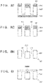
- Figs. 8A to 8I are views for explaining the steps of a method of manufacturing the observation unit 22.
- An outline of this manufacturing method is to place the plate 222 on the lower surface of the plate 221 and bond the plates 221 and 222 by anodic bonding. Note that main steps of this manufacturing method will be focused and described below in order to simplify the explanation, but washing, annealing, and the like can also be performed properly as needed.
- a semiconductor substrate SB1 as a material of the plate 221 is prepared and oxidized.
- a silicon substrate can preferably be used as the semiconductor substrate SB1.
- the film thickness of an oxide film OX1 formed in this step is about 0.12 ⁇ m (1,200 ⁇ ).
- the surface of the structure (this expression will be used including the oxide film OX1 to simplify the explanation, and this similarly applies to the following explanation) obtained in the step in Fig. 8A is partially etched, thereby partially removing the oxide film OX1 so as to expose a portion of the upper surface of the semiconductor substrate SB1, and partially removing the exposed semiconductor substrate SB1.
- This etching process is performed by, for example, inductively coupled plasma etching. A portion removed by etching will be called an etching portion hereinafter.
- the upper surface of the structure obtained in the step shown in Fig. 8B is oxidized, thereby covering the etching portion and the existing oxide film OX1 with a new oxide film OX1.
- the semiconductor substrate SB1 having a step on the upper surface and the oxide film OX1 covering the upper surface are obtained.
- the upper surface of the oxide film OX1 can also be planarized by performing polishing such as CMP (Chemical Mechanical Polishing).
- a metal film M1 is formed on the upper surface of the structure obtained in the step shown in Fig. 8C .
- This step can be performed by a well-known deposition method such as sputtering.
- Aluminum can preferably be used as the material of the metal film M1. Note that the film thickness of the metal film M1 formed in this step is about 0.4 ⁇ m.
- the upper surface of the structure obtained in the step shown in Fig. 8D is partially etched, thereby partially removing the metal film M1 and the oxide film OX1 so as to partially expose the upper surface of the semiconductor substrate SB1, and partially removing the exposed semiconductor substrate SB1.
- the etching portion formed in the step shown in Fig. 8E is deepened by further etching the etching portion formed in the step shown in Fig. 8E . Consequently, the etching portion reaches the vicinity of the oxide film OX1 on the lower surface side of the semiconductor substrate SB1.
- polishing such as CMP is performed on the lower surface side of the structure obtained in the step shown in Fig. 8F , thereby changing the etching portion into through holes H3 extending through the semiconductor substrate SB1.
- the metal film M1 and the oxide film OX1 are removed from the structure obtained in the step shown in Fig. 8G , and surface oxidation is additionally performed to form an oxide film (not shown).
- the structure thus obtained is a plate 221.
- a plate 222 is placed on the plate 221 obtained in the step shown in Fig. 8H , and these plates are bonded by anodic bonding.
- a material that is transparent and secures flatness is adopted as the material of the plate 222, so bonding can also be performed by another appropriate bonding method such as solid-phase bonding in accordance with the adopted material.
- the observation unit 22 can be manufactured by the above procedure.
- An observation chip functioning as the observation unit 22 described above is actually obtained by collectively manufacturing a plurality of plates 221 at once.
- the abovementioned processing for manufacturing a plurality of plates 221 is performed on a first mother plate (in this case, a silicon substrate) having a predetermined size with which the plurality of plates 221 can be processed.
- a second mother plate in this case, a glass plate
- a cutting step is performed to cut the bonded first and second mother plates into chips by dicing or the like. As a consequence, a plurality of observation chips can be manufactured at once.
- the step wall surface formed as a step is preferably processed into a right angle so as to be perpendicular to other surfaces.
- a silicon substrate (silicon wafer) having a thickness that enables right-angle processing is preferably used in order to process the boundary portion into a right angle.
- the observation holder 2 includes the accommodation unit 21 and the observation unit 22.
- the accommodation unit 21 has a rectangular shape in a planar view and can accommodate an observation target (for example, a blood).
- the observation unit 22 is formed on the lower portion of the accommodation unit 21 and so configured that an observation target accommodated in the accommodation unit 21 can be observed from below.
- the accommodation unit 21 includes the accommodation unit main body 210 and the accommodation unit upper portion 211 formed above the accommodation unit main body 210.
- the plurality of holes H1 for accommodating observation targets are formed in the accommodation unit main body 210.
- the accommodation unit upper portion 211 includes the walls 2111a surrounding the opening 2112 in the upper portion of the accommodation unit main body 210.
- the walls 2111a function as a storage or a dam for storing a predetermined liquid (liquid culture medium) in the opening 2112.
- the plurality of holes H1 are arrayed in the horizontal direction, and each hole H1 vertically extends through the accommodation unit main body 210 and communicates with the opening 2112. Also, two adjacent holes H1 of the plurality of holes H1 are connected in the observation unit 22.
- an observation target that can be positioned between two adjacent holes H1 can be observed from below via the observation unit 22.
- a plurality of observation holders 2 are arranged on the predetermined support base 11, therefore, it is possible to simply and efficiently observe many observation targets or a plurality of different characteristics of one observation target at once.
- a hydrophilic treatment is performed on each surface that comes in contact with a liquid, and this makes it possible to easily and reliably store the liquid, inject samples, and arrange the samples in the observation position.
- any of the plurality of holes H1 can be accessed from the opening H2. Therefore, the user such as a medical doctor, a laboratory technician, or a researcher can relatively easily accommodate an observation target in a given hole H1.
- each element is denoted by a name related to its function in order to facilitate understanding.
- each element is not limited to a member having the contents explained in the embodiment as its main function and can also include the contents explained in the embodiment as its auxiliary function.
Landscapes
- Physics & Mathematics (AREA)
- Chemical & Material Sciences (AREA)
- Analytical Chemistry (AREA)
- General Physics & Mathematics (AREA)
- Optics & Photonics (AREA)
- Sampling And Sample Adjustment (AREA)
- Microscoopes, Condenser (AREA)
- Investigating Or Analysing Biological Materials (AREA)
- Investigating Or Analysing Materials By Optical Means (AREA)
- Investigating Materials By The Use Of Optical Means Adapted For Particular Applications (AREA)
- Testing Or Measuring Of Semiconductors Or The Like (AREA)
Abstract
Description
- The present invention relates to an observation holder (mainly a cell observation holder).
-
PTL 1 andPTL 2 describe the structure of an observation holder for accommodating an observation target such that the target is observable. The observation holder is so configured that a cell as an observation target can be observed from below the observation holder. By using the observation holder like this, a user such as a medical doctor, a laboratory technician, or a researcher can observe an observation target by an image via a predetermined observation instrument (for example, a microscope or an imaging camera). Examples of the observation target are a tissue or a body fluid itself as a constituent element of a cell of an animal including a human, for example, a blood or a lymph of a human or a mouse, an ascites and a peritoneal lavage fluid, a bronchoalveolar lavage fluid, various white blood cells and other cells as components thereof, and a cancer cell separated from a tissue and an established cultured cell; and a separated plant cell including a microorganism such as a fungus. An observation holder that allows a user to simultaneously observe a plurality of different functions of a cell as an observation target by using an image can be used in, for example, a mass screening test for a newborn baby and diagnoses of various diseases (PTL 3). -
- PTL 1:
Japanese Patent Laid-Open No. 2007-124904 - PTL 2:
Japanese Patent Laid-Open No. 2011-038923 - PTL 3:
Japanese Patent Laid-Open No. 2018-102295 - It is necessary to further improve the structure of the above-described observation holder to make it possible to simply and efficiently observe a plurality of different characteristics and a plurality of different functions of many cells as observation targets at once, and to simultaneously perform these observations and measurements on many samples, for example, many patient samples at once.
- It is an exemplary object of the present invention to provide a novel structure of an observation holder capable of performing simple and efficient observations of a plurality of different characteristics of one observation target, and further capable of performing these observations on many samples at once.
- One aspect of the present invention relates to an observation holder, and the observation holder is an observation holder including an accommodation unit having a rectangular shape in a planar view and configured to accommodate an observation target, and an observation unit formed below the accommodation unit, characterized in that the observation unit is configured such that an observation target accommodated in the accommodation unit can be observed from below, the accommodation unit includes an accommodation unit main body in which a plurality of holes for accommodating an observation target are formed to be spaced apart from each other, and an accommodation unit upper portion formed on an upper portion of the accommodation unit main body, the accommodation unit upper portion includes a wall surrounding a space above the accommodation unit main body, as a storage for storing a predetermined liquid, an opening is formed above the space in the accommodation unit upper portion, and the plurality of holes are arrayed in a horizontal direction, each hole vertically extends through the accommodation unit main body and communicates with the opening, and two adjacent holes of the plurality of holes are connected in the observation unit.
- According to the present invention, it is possible to simply and efficiently observe a plurality of different characteristics of one observation target.
- Other features and advantages of the present invention will be apparent from the following description taken in conjunction with the accompanying drawings. Note that the same reference numerals denote the same or like components throughout the accompanying drawings.
- The accompanying drawings, which are incorporated in and constitute a part of the specification, illustrate embodiments of the invention and, together with the description, serve to explain principles of the invention.
-
Fig. 1 is a schematic side view showing a configuration example of an observation apparatus; -
Fig. 2 is a perspective view showing a part of the observation apparatus; -
Fig. 3 is a perspective view showing an observation holder; -
Fig. 4 is an exploded view showing the observation holder; -
Fig. 5 is a perspective view of a plate forming a part of an observation unit; -
Fig. 6 is a lower side perspective view showing the observation holder;Fig. 7A is a sectional view showing the observation holder; -
Fig. 7B is a sectional view showing the observation holder; -
Fig. 8A is a view for explaining a manufacturing method of the observation unit; -
Fig. 8B is a view for explaining the manufacturing method of the observation unit; -
Fig. 8C is a view for explaining the manufacturing method of the observation unit; -
Fig. 8D is a view for explaining the manufacturing method of the observation unit; -
Fig. 8E is a view for explaining the manufacturing method of the observation unit; -
Fig. 8F is a view for explaining the manufacturing method of the observation unit; -
Fig. 8G is a view for explaining the manufacturing method of the observation unit; -
Fig. 8H is a view for explaining the manufacturing method of the observation unit; and - Fig. 81 is a view for explaining the manufacturing method of the observation unit.
- Hereinafter, embodiments will be described in detail with reference to the attached drawings. Note, the following embodiments are not intended to limit the scope of the claimed invention, and limitation is not made to an invention that requires a combination of all features described in the embodiments. Two or more of the multiple features described in the embodiments may be combined as appropriate. Furthermore, the same reference numerals are given to the same or similar configurations, and redundant description thereof is omitted.
-
Fig. 1 is a schematic side view showing anobservation apparatus 1 according to an embodiment, andFig. 2 is a perspective view showing a part of theobservation apparatus 1. Theobservation apparatus 1 includes asupport base 11, animaging unit 12, and amoving mechanism 13, and also includes anobservation preparation unit 14. In addition, an observation holder 2 (to be described later) not included in theobservation apparatus 1 is mounted on thesupport base 11. - The
support base 11 is a plate-like member having a predetermined thickness. Thesupport base 11 can support a plurality ofobservation holders 2, and the plurality ofobservation holders 2 are arranged in a horizontal direction on the support table 11. The horizontal direction herein mentioned is a given direction parallel to the upper surface of thesupport base 11 in a horizontal posture. As will be described in detail later, eachobservation holder 2 can accommodate a predetermined observation target. An example of the observation target is a white blood cell of an animal such as a human blood. - Note that in
Fig. 2 , an X direction indicates one of the array directions of the plurality ofobservation holders 2, and a Y direction indicates the other direction (a direction perpendicular to the X direction) of the array directions. Also, assuming that the array directions are horizontal directions, a Z direction indicates a vertical direction or an up-down direction. - In this embodiment, as will be described in detail later, six
recesses 111 are formed in thesupport base 11 at equal intervals in the X direction, and are arranged in two rows in the Y direction. Theobservation holder 2 can be mounted as it is fitted in eachrecess 111. Also, anopening 112 extending in the vertical direction is formed in a bottom 111a of eachrecess 111 so that the mountedobservation holder 2 can be viewed from below. - The bottom 111a of the
recess 111 forms theopening 112, and also forms a mountingportion 111b by extending into the form of a flange toward the center from the edges of theopening 112 so that theobservation holder 2 can be mounted. Theobservation holder 2 is mounted by abutting a plate (second plate) 222 of an observation unit 22 (to be described later) of theobservation holder 2 against the mountingportion 111b. In addition, the side walls of therecess 111 form a surrounding wall (guide wall) 111c for regulating the movement of theobservation holder 2 in the horizontal direction when theobservation holder 2 is fitted. The surrounding wall 111c is set to be higher than a main bodylower portion 210L of a main body 210 (to be described later) of theobservation holder 2, and lower than a main body upper portion of themain body 210. - The
imaging unit 12 can capture an image of an observation target accommodated in theobservation holder 2, and is installed below thesupport base 11 in this embodiment. As theimaging unit 12, it is possible to use a device capable of capturing a moving image and/or a still image, for example, a well-known camera including a CCD/CMOS image sensor or the like. Note that in the following explanation, imaging by theimaging unit 12 can also be expressed as observation. - The moving
mechanism 13 can horizontally move theimaging unit 12 relative to thesupport base 11, and the moving direction is practically parallel to the X direction in this embodiment. When the movingmechanism 13 moves theimaging unit 12, theimaging unit 12 is moved to face each of the plurality ofopenings 112 formed along the X direction. As the movingmechanism 13, it is possible to use a well-known slider mechanism, for example, arail 131 slidably supporting theimaging unit 12 in the X direction, a nut (not shown) included in theimaging unit 12, a ball screw formed parallel to therail 131 and rotatably supported by being engaged with the nut, and anelectric motor 132 for rotating the ball screw. - In this embodiment, as shown in
Fig. 2 , the plurality ofobservation holders 2 include two rows arranged in the Y direction of the sixrecesses 111 arranged in the X direction, that is, include a total of twelverecesses 111. The movingmechanism 13 can move theimaging unit 12 in the X direction and the Y direction. Alternatively, it is also possible to move theimaging unit 12 in only the X direction by the movingmechanism 13, and install two sets of a combination of the movingmechanism 13 and theimaging unit 12 in the Y direction. Examples of theimaging unit 12 are a vision camera, an objective lens, and another imaging device. When using an objective lens as theimaging unit 12, it is possible to form theimaging unit 12 as an index table, set a plurality of objective lenses having different magnifications on the index table, and select an objective lens having a given magnification by index rotation. - The
observation preparation unit 14 is a unit for a user to perform a preparation work. Theobservation preparation unit 14 includes apreparation support base 141 and a moving mechanism (second moving mechanism) 142. Thepreparation support base 141 can support theobservation holder 2 in a state (unaccommodated state) in which no observation target is accommodated. Arecess 111 and anopening 112 are formed in thepreparation support base 141 like those of thesupport base 11. As will be described in detail later, the user can make preparations for observation by accommodating an observation target in theobservation holder 2 supported by thepreparation support base 141, by injecting the observation target by using a predetermined instrument or device, for example, a manual injector such as a syringe or a dropper, or an automatic injector such as a vertical 6-axis robot or a SCARA robot. - Note that workers such as a medical doctor, a laboratory technician, and a researcher can be taken as typical examples of the user, but the user can also be an industrial robot or a manipulator that operates based on instructions from one or more of these workers.
- The moving
mechanism 142 can move thepreparation support base 141 in a predetermined direction (at least the Z direction). When using thepreparation support base 141, for example, the height of thepreparation support base 141 can be adjusted by operating the movingmechanism 142, thereby making preparations for observation. As the movingmechanism 142, it is possible to use a well-known slider mechanism, for example, arail 1421 for slidably supporting thepreparation support base 141, and anelectric motor 1422 for sliding thepreparation support base 141 along therail 1421. - As will be described in detail later, in the
observation apparatus 1 as explained above, the user injects an observation target into theobservation holder 2 supported by thepreparation support base 141, thereby making preparations for observation. After that, the user transfers theobservation holder 2 from the preparation support table 141 to the support table 11, thereby completing the setting of theobservation holder 2 with respect to theobservation apparatus 1. Then, the user observes the observation target from below theobservation holder 2 by using theimaging unit 12. The preparations of the observation target are to make it possible to cause theimaging unit 12 to capture an image of the observation unit 22 (to be described later) of theobservation holder 2 from below, and inject the observation target into a predetermined position (observation position) of theobservation holder 2 while checking the captured image, thereby placing a cell as the observation target in the observation position. Theobservation apparatus 1 can also be called an observation system, an evaluation apparatus, an evaluation system, a diagnostic apparatus, a diagnostic system, or the like. -
Fig. 3 shows a perspective view of theobservation holder 2.Fig. 4 shows an exploded view of theobservation holder 2. Theobservation holder 2 includes anaccommodation unit 21 and theobservation unit 22. Note thatFigs. 3 and4 depict the X, Y, and Z directions corresponding to those shown inFig. 2 . - The
accommodation unit 21 has a rectangular shape, that is, an oblong shape in this embodiment in a planar view (a view point in the Z direction, a top view), and can accommodate the observation target described above. In this embodiment, theaccommodation unit 21 includes an accommodation unitmain body 210 and an accommodation unitupper portion 211. The accommodation unitmain body 210 has aprojection 2101 in the central portion along a lateral direction (the Y direction inFig. 3 ) in a planar view. Theprojection 2101 is extended in a longitudinal direction (the X direction inFig. 3 ) in a planar view. As a consequence, step surfaces 2102 are formed on the both sides of theprojection 2101. - A plurality of holes H1 for accommodating an observation target are formed to be spaced apart from each other in the
projection 2101 of the accommodation unitmain body 210. The plurality of holes H1 are arrayed in the X direction and the Y direction, and each hole H1 is so formed as to extend through theprojection 2101 in the Z direction. A hydrophilic treatment can be performed on each surface of the plurality of holes H1 formed in the accommodation unitmain body 210 and brought into contact with a liquid. Anupper surface 210U of theprojection 2101 is planarized, and each hole H1 has an opening end in theupper surface 210U. That region of theupper surface 210U, which includes the holes H1 and their surroundings, is aflat region 210R (seeFig. 3 ). - The accommodation unit
upper portion 211 is formed on the upper portion of the accommodation unitmain body 210, and has anopening 2112 for forming a space above theflat region 210R of the accommodation unitmain body 210 when the accommodation unitupper portion 211 is set on the accommodation unitmain body 210. In other words, the space surrounded bywalls 2111a in the accommodation unitupper portion 211 is theopening 2112. Theopening 2112 is formed to extend through the accommodation unitupper portion 211, and has different opening areas in the upper and lower portions of the accommodation unitupper portion 211. Alower opening 2112b is a portion into which theprojection 210 is inserted, and is formed to have almost the same size as that of the shape of theprojection 210. - On the other hand, an
upper opening 2112a is a portion that forms a space above theflat region 210R, and is formed to have almost the same size as that of the shape of theflat region 210R. That is, the opening area of theupper opening 2112a is smaller than that of thelower opening 2112b. A portion of theupper surface 210U of theprojection 210 engages with a step surface SS between theupper opening 2112a and thelower opening 2112b, and as a consequence theflat region 210R faces theupper opening 2112a. At the same time, a portion of alower portion 211L of the accommodation unitupper portion 211 engages with thestep surface 2102 of the accommodation unitmain body 210. In this state, the space surrounded by theupper opening 2112a and theflat region 210R functions as a storage for storing a predetermined liquid. Note that anuppermost portion 2112c of theopening 2112 is formed to increase in a tapered shape. - As described above, the
opening 2112 has different sectional areas in the upper and lower portions of the accommodation unitupper portion 211, and the storage volume is decreased by forming the storage in theupper opening 2112a having a small sectional area. This makes it possible to decrease the amount of a liquid to be stored in the storage. Also, a hydrophilic treatment like that performed on the surfaces forming the plurality of holes H1 can be performed on the surfaces formed as the storage in the accommodation unitupper portion 211 and brought into contact with a stored liquid. As the liquid, a liquid culture medium corresponding to an observation target can be used, but it is also possible to use other solutions such as a normal saline solution. - As will be described in detail later, the plurality of holes H1 formed in the accommodation unit
main body 210 are not used independently of each other, but used as a U-shaped path by pairing adjacent holes H1 two by two and connecting the lower ends of the holes H1 in theobservation unit 22. - In this embodiment, the accommodation unit
main body 210 is made of a non-translucent material. Also, the accommodation unitupper portion 211 is made of a translucent material. Note that "non-translucent" means that the transmittance of visible light is relatively low. For example, the transmittance is 50% or less, preferably 30% or less, and more preferably 10% or less. Also, "translucent" means that the transmittance of visible light is relatively high. For example, the transmittance is 50% or more, preferably 70% or more, and more preferably 90% or more. As another embodiment, the accommodation unitupper portion 211 can also be made of a non-translucent material. - Note that each of the accommodation unit
main body 210 and the accommodation unitupper portion 211 can be formed by one member, and, when each of them is formed by one member, both of them are preferably made of a non-translucent material. - The
observation unit 22 is formed below theaccommodation unit 21, and so configured that an observation target accommodated in theaccommodation unit 21 can be observed from below by using theimaging unit 12. Theobservation unit 22 includes a plate (first plate) 221 and a plate (second plate) 222. Theplate 221 covers the accommodation unitmain body 210 from below, and theplate 222 covers theplate 221 from below. Theplate 222 covers theplate 221 from below and is made of a practically translucent material. Theplate 221 is partially made of a translucent material in this embodiment, but can also be entirely made of a non-translucent material or a reflective material. It is also possible to use a material having a dark-color (for example, black) surface. As theplate 221, it is possible to use, for example, a silicon disk (silicon wafer) microfabricated by anisotropic dry etching (inductively coupled plasma-reactive ion etching). In this embodiment, rectangular members having the same size in a planar view are used as theplates plates Fig. 5 . -
Fig. 5 is a perspective view of theplate 221. In this embodiment, a plurality of through holes H3 corresponding to the plurality of holes H1 are formed in theplate 221. A cavity CC1 for connecting two adjacent holes (for example, H3a and H3b) of the plurality of through holes H3 is formed in the lower surface of theplate 221. The cavity CC1 is formed such that its outer edge surrounds the two through holes H3. That is, on the upper surface side of theplate 221, the plurality of through holes H3 are formed independently of each other in positions corresponding to the plurality of holes H1. On the lower surface side of theplate 221, however, the plurality of through holes H3 are partially not independent of each other because the two adjacent holes H3 communicate with each other by the cavity CC1. In this embodiment, the cavity CC1 is formed into an elliptical shape in a planar view. The cavity CC1 can also be called a terrace, a recess, or the like. - The cavity CC1 includes a flat portion PL between the two adjacent through holes H3. The flat portion PL includes a flat surface PL1. Also, the outer edge of the cavity CC1 is formed by side walls WP. The side walls WP include circumferential wall portions WP1 and WP2, and two wall portions WP3. The circumferential wall portions WP1 and WP2 correspond to the circumferential portions of the ellipse, and the circumferential wall portions WP3 correspond to straight portions of the ellipse. In addition, the circumferential wall portion WP1 faces one (in this case, H3a) of the two through holes H3, and the circumferential wall portion WP2 faces the other (in this case, H3b) of the two through holes H3.
- More specifically, the circumferential wall portion WP1 includes a cylindrical upper circumferential wall portion WP1U formed to have the same size as that of the through hole H3, and a semi-cylindrical lower circumferential wall portion WP1L formed to be continuous to the upper circumferential wall portion WP1U and to have the same size as that of the upper circumferential wall portion WP1U. Also, as in the circumferential wall portion WP1, the circumferential wall portion WP2 includes a cylindrical upper circumferential wall portion WP2U formed to have the same size as that of the through hole H3, and a semi-cylindrical lower circumferential wall portion WP2L formed to be continuous to the upper circumferential wall portion WP2U and to have the same size as that of the upper circumferential wall portion WP2U.
- The two circumferential wall portions WP3 are so formed as to form continuous surfaces connecting to the circumferential wall portions WP1 and WP2. More specifically, the circumferential wall portions WP3 are formed as continuous surfaces that connect the lower circumferential wall portion WP1L of the circumferential wall portion WP1 to the lower circumferential wall portion WP2L of the circumferential wall portion WP2, which is formed to correspond to the lower circumferential wall portion WP1L of the circumferential wall portion WP1, and that have the same height as that of the lower circumferential wall portions WP1L and WP2L.
- In this embodiment, each through hole H3 is formed into an almost circular shape in a planar view, each of the upper circumferential wall portions WP1U and WP2U of the circumferential wall portions WP1 and WP2 is formed to draw a circle having the same diameter as that of the through hole H3, each of the lower circumferential wall portions WP1L and WP2L of the circumferential wall portions WP1 and WP2 is formed to draw an arc of a semicircle having the same diameter as that of the through hole H3, and the circumferential wall portion WP3 is so formed as to draw an almost straight line.
- Since the
plate 222 having a flat plate shape covers the lower surface, that is, the cavity CC1 of theplate 221 formed as described above, a passage formed by a space surrounded by the circumferential wall portions WP1, WP2, and WP3, the flat portion PL, and theplate 221 is formed as apassageway 220W (seeFig. 6 ). Consequently, the lower portions of the two adjacent through holes H3 are connected via thepassageway 220W, so the two through holes H3 connect to each other to form one passage. By making the through holes H3 respectively corresponding to the two adjacent holes H1 communicate with each other on the upper surface side of theplate 221, theimaging unit 12 can observe an observation target accommodated in theaccommodation unit 21 when the observation target stays in thepassageway 220W. Also, a hydrophilic treatment can be performed on each surface of the cavity CC1 that forms thepassageway 220W by making the plurality of adjacent holes H1 communicate with each other, and comes in contact with a liquid moving through thepassageway 220W. - Note that the shape of the side wall WP is not limited to that of this embodiment, and need only be so formed as to include the two through holes H3 in a planar view. Note also that the size (diameter) of the through hole H3, the size (diameter) of WP1, and the size (diameter) of WP1 are preferably set such that their arcs match (that is, are preferably the same size). However, they can also be different sizes provided that there is no influence on visibility or the like during observation.
- Referring to
Fig. 4 again, a definingportion 210a for defining the position of theplate 221 is formed in the main bodylower portion 210L of the accommodation unitmain body 210. In this embodiment, the definingportion 210a is a depressed portion formed by depressing the bottom surface of the accommodation unitmain body 210, and the shape of this depressed portion follows the outer shape of theplate 221 in a planar view. The depth of the depressed portion is equal to or larger than the thickness of theplate 221. By fitting theplate 221 of theobservation unit 22 in the depressed portion as the definingportion 210a, it is possible to appropriately position theobservation unit 22 with respect to theaccommodation unit 21. In practice, however, it is only necessary to be able to appropriately align the upper circumferential wall portions WP1U and WP2U of the circumferential wall portions WP1 and WP2 corresponding to the through holes H3. Instead/in addition, a predetermined mark such as printing or a notch can also be formed as the definingportion 210a. -
Fig. 6 shows a lower side perspective view of theobservation holder 2 obtained by assembling theaccommodation unit 21 and theobservation unit 22 described above. Theplate 222 of theobservation unit 22 is made of a translucent material. Accordingly, the imaging unit 12 (seeFigs. 1 and2 ) can capture an image of an observation target via theobservation unit 22 when the observation target stays in thepassageway 220W connecting the two through holes H3 (for example, H3a and H3b). - As the flat surface PL1 forming a part of the
passageway 220W, the entire region between the two through holes H3 (for example, H3a and H3b) is preferably formed as a flat surface, but the flat surface PL1 included in the flat portion PL can also be formed in only a part of that region. In this case, a step can exist in a part of that region (the flat surface PL1 can exist at a height different from that of the rest of the flat portion PL). -
Fig. 7A shows a sectional view of theobservation holder 2, in which a vertical surface passing the plurality of holes H1 and taken along the X direction is a section.Fig. 7B shows a sectional view taken along a line VIIB - VIIB inFig. 7A. Fig. 7B also includes a partially enlarged view of theobservation unit 22 surrounded by the dotted lines. In theobservation unit 22, two adjacent holes H1 of the plurality of holes H1 formed in the accommodation unitmain body 210 are connected via the corresponding through holes H3a and H3b and thepassageway 220W, so a pair of the holes H1 form one passage. - When an observation target is a blood, for example, the hole H1 and the through hole H3 can be formed to have a diameter of about 700 [µm] to 1,300 [µm], more preferably about 900 [µm] to 1,100 [µm], and further preferably about 1,000 [µm]. The distance between the two through holes H3 can be about 350 [µm] to 650 [µm], more preferably about 450 [µm] to 550 [µm], and further preferably about 500 [µm]. In this case, the cavity CC1 can be determined in accordance with the size of particles existing in a body fluid to be used. When using a human blood, for example, the depth can be about 2 [µm] to 7 [µm], more preferably about 3 [µm] to 5 [µm], and further preferably about 4 [µm] in accordance with the size of white blood cells. When using cancer cells separated from a tissue, the depth can be about 12 [µm] to 5 [µm], preferably about 10 [µm] to 6 [µm], and more preferably about 8 [µm]. Note that when forming the flat surface PL1 including a step on the flat portion PL, it is possible to set the depth of the flat portion PL at 50 to 100 [µm], and set the distance between the flat surface PL1 and the surface of the
plate 222 forming thepassageway 220W to a distance which is smaller than the size of particles existing in a body fluid or the like to be used and at which the particles can move. - To appropriately implement observation of an observation target by the
imaging unit 12, theimaging unit 12 is preferably installed so as to scan a portion immediately below the flat surface PL1 in the cavity CC1 between the two through holes H3 (for example, H3a and H3b) so that a +Z direction is the center of a designated range. - In this embodiment, as can be seen from
Figs. 7A and 7B , the accommodation unitmain body 210 and the accommodation unitupper portion 211 are so configured that their widths in one direction (in this case, the Y direction) of the horizontal direction are equal to each other. This makes it possible to decrease the size of theaccommodation unit 21, that is, theobservation holder 2 itself, and to densely array a plurality ofobservation holders 2 on thesupport base 11. In this embodiment, the dense array is possible in particularly one direction (int this case, the Y direction) of the horizontal direction. - Also, in this embodiment, the accommodation unit
main body 210 and the accommodation unitupper portion 211 are so configured that their widths in the other direction (in this case, the X direction) of the horizontal direction are different from each other. A configuration like this can decrease the size of theobservation unit 22 in which the cavity CC1 as the imaging range of theimaging unit 12 is formed, the size of the accommodation unitmain body 210 in which the plurality of holes H1 are formed, and the size of the accommodation unitupper portion 211 in which theopening 2112 is formed, and can reduce the amount of the manufacturing materials of theobservation holder 2. It is also possible to prevent the user from failing to hold the observation holder 2 (and, for example, an accompanying fall of the observation holder 2). Note that these widths can be different from each other in one of the X and Y directions, and can also be equal to each other in both the directions as another embodiment. - As shown in
Fig. 3 , aninformation portion 23 is formed in the accommodation unitupper portion 211 of theobservation holder 2 of this embodiment. More specifically, theinformation portion 23 is formed on an accommodation unit upper portionupper surface 211U. Theinformation portion 23 can give information about an observation target. This information can also be expressed as observation target information, and examples of the information are the name of a subject and the collection date of an observation target. The information can also be code information to be managed in association with the name of a subject, the collection date of an observation target, and the like. As this code data, it is possible to use, for example, number information using a combination of a plurality of numbers, or two-dimensional data information (for example, a barcode or a QR code). The code information can be read by a code information reader (not shown). Theinformation portion 23 can be formed such that the observation target information can be printed, and can also be formed such that a seal on which the observation target information is described can be adhered. The user can manage an observation target relatively easily by using theinformation portion 23. - The user can access a given hole H1 from the opening H2 of the
observation holder 2 supported on thepreparation support base 141 by using a predetermined instrument such as a syringe or a dropper, and can accommodate an observation target in each hole H1. More specifically, a predetermined liquid (liquid culture medium) is filled in the space SP1 and the hole H1, and then an observation target (for example, a blood) is rapidly injected into one of two adjacent holes (a pair of holes) H1 connected by theobservation unit 22. Consequently, a part of the liquid flows into thepassageway 220W and the cavity CC1. If cells sufficient for observation do not flow into the cavity CC1, the cells can be supplied to the cavity CC1 by performing negative pressure suction in the other hole H1. As can be understood fromFig. 3 , theuppermost portion 2112c of theopening 2112 can be so formed as to form an inclined surface or the like. This allows the user to appropriately access a given hole H1 from theopening 2112. - The
observation holder 2 in which the observation target is already accommodated is transferred to thesupport base 11, and the observation target can be observed by theimaging unit 12 from below theobservation holder 2 via theobservation unit 22. - In this embodiment as described earlier, the accommodation unit
main body 210 is made of a non-translucent material, and the accommodation unitupper portion 211 is made of a translucent material. Since the accommodation unitmain body 210 is made of a non-translucent material, the contrast between the flat surface PL1 as an observation target portion and the through hole H3 as a non-observation target portion can be increased. Accordingly, an observation target injected into a portion of the flat surface PL1 as an observation target portion can easily be observed from below by theimaging unit 12 via theobservation unit 22. In addition, since the accommodation unitupper portion 211 is made of a translucent material, the user can visually confirm the interiors of theopening 2112 and each hole H1 both from above and from side to side when accommodating an observation target in the hole H1. - As another embodiment, it is also possible to automatically accommodate an observation target by using an automatic machine, instead of the work in which the user accesses a given hole H1 from the
opening 2112 and accommodates an observation target in each hole H1 by using a predetermined instrument such as a syringe or a dropper. In this case, the accommodation unitupper portion 211 need not be made of a translucent material, and both the accommodation unitmain body 210 and the accommodation unitupper portion 211 can be made of a non-translucent material. When both the accommodation unitmain body 210 and the accommodation unitupper portion 211 are made of a non-translucent material, the position of each hole H1 can visually be confirmed from above by a detecting means (for example, a camera) included in the automatic machine, so the work of accommodating an observation target can efficiently be performed. - Referring to
Fig. 2 again, thesupport base 11 for supporting theobservation holder 2 includes therecess 111 on which theobservation holder 2 is mounted by being fitted therein, and theopening 112 vertically extending through the bottom portion of therecess 111. Since the mountingportion 111b of therecess 111 supports the lower surface of the peripheral portion of theplate 222, the height to the flat surface PL1 as an observation target portion is maintained constant, and this can appropriately implement observation of an observation target from below by theimaging unit 12. This similarly applies to thepreparation support base 141. - The
observation holder 2 can be disposed after the observation of the observation target is complete, and hence can also be called a disposable holder or the like. That is, when using a disposable holder as the observation holder 2 (when using a holder whose disposal is recommended after it is once used), it is possible to further prevent mixing of an observation target different from a measurement sample, that is, contamination. Accordingly, thewhole observation holder 2 can also be unitized. For example, it is possible to non-detachably fix theaccommodation unit 21 and the observation unit 22 (elements configuring them), and to non-detachably fix the accommodation unitmain body 210 and the accommodation unitupper portion 211 in theaccommodation unit 21. - In this embodiment, the
observation holder 2 as a disposable holder is downsized by giving respective corresponding shapes or outer shapes to theobservation unit 22 including the cavity CC1, the accommodation unitmain body 210 including the plurality of holes H1, and the accommodation unitupper portion 211 including theopening 2112, and hence is usable effectively. - As described earlier, the
observation unit 22 including theplates accommodation unit 21. As a consequence, theaccommodation unit 21 and theobservation unit 22 form a vessel. In this viewpoint, theobservation unit 22 can also be called an accommodation unit bottom portion, a vessel bottom portion, or the like, and theobservation holder 2 can also be called an observation vessel or the like. Theobservation unit 22 like this can individually be prepared as an observation chip attachable as a component to theobservation holder 2, and can be manufactured by using a well-known semiconductor manufacturing technique. -
Figs. 8A to 8I are views for explaining the steps of a method of manufacturing theobservation unit 22. An outline of this manufacturing method is to place theplate 222 on the lower surface of theplate 221 and bond theplates - In the step shown in
Fig. 8A , a semiconductor substrate SB1 as a material of theplate 221 is prepared and oxidized. A silicon substrate can preferably be used as the semiconductor substrate SB1. Note that the film thickness of an oxide film OX1 formed in this step is about 0.12 µm (1,200 Å). - In the step shown in
Fig. 8B , the surface of the structure (this expression will be used including the oxide film OX1 to simplify the explanation, and this similarly applies to the following explanation) obtained in the step inFig. 8A is partially etched, thereby partially removing the oxide film OX1 so as to expose a portion of the upper surface of the semiconductor substrate SB1, and partially removing the exposed semiconductor substrate SB1. This etching process is performed by, for example, inductively coupled plasma etching. A portion removed by etching will be called an etching portion hereinafter. - In the step shown in
Fig. 8C , the upper surface of the structure obtained in the step shown inFig. 8B is oxidized, thereby covering the etching portion and the existing oxide film OX1 with a new oxide film OX1. In this step, the semiconductor substrate SB1 having a step on the upper surface and the oxide film OX1 covering the upper surface are obtained. After the oxidation, the upper surface of the oxide film OX1 can also be planarized by performing polishing such as CMP (Chemical Mechanical Polishing). - In the step shown in
Fig. 8D , a metal film M1 is formed on the upper surface of the structure obtained in the step shown inFig. 8C . This step can be performed by a well-known deposition method such as sputtering. Aluminum can preferably be used as the material of the metal film M1. Note that the film thickness of the metal film M1 formed in this step is about 0.4 µm. - In the step shown in
Fig. 8E , the upper surface of the structure obtained in the step shown inFig. 8D is partially etched, thereby partially removing the metal film M1 and the oxide film OX1 so as to partially expose the upper surface of the semiconductor substrate SB1, and partially removing the exposed semiconductor substrate SB1. - In the step shown in
Fig. 8F , the etching portion formed in the step shown inFig. 8E is deepened by further etching the etching portion formed in the step shown inFig. 8E . Consequently, the etching portion reaches the vicinity of the oxide film OX1 on the lower surface side of the semiconductor substrate SB1. - In the step shown in
Fig. 8G , polishing such as CMP is performed on the lower surface side of the structure obtained in the step shown inFig. 8F , thereby changing the etching portion into through holes H3 extending through the semiconductor substrate SB1. - In the step shown in
Fig. 8H , the metal film M1 and the oxide film OX1 are removed from the structure obtained in the step shown inFig. 8G , and surface oxidation is additionally performed to form an oxide film (not shown). The structure thus obtained is aplate 221. - In the step shown in Fig. 81, a
plate 222 is placed on theplate 221 obtained in the step shown inFig. 8H , and these plates are bonded by anodic bonding. A material that is transparent and secures flatness is adopted as the material of theplate 222, so bonding can also be performed by another appropriate bonding method such as solid-phase bonding in accordance with the adopted material. Theobservation unit 22 can be manufactured by the above procedure. - An observation chip functioning as the
observation unit 22 described above is actually obtained by collectively manufacturing a plurality ofplates 221 at once. To manufacture a plurality of observation chips at once, the abovementioned processing for manufacturing a plurality ofplates 221 is performed on a first mother plate (in this case, a silicon substrate) having a predetermined size with which the plurality ofplates 221 can be processed. Then, a second mother plate (in this case, a glass plate) having the same size as that of the first mother plate is placed on it, and the two plates are bonded. After that, a cutting step is performed to cut the bonded first and second mother plates into chips by dicing or the like. As a consequence, a plurality of observation chips can be manufactured at once. - Note that when manufacturing different types of observation chips each having the flat surface PL1 including a step in the flat portion PL, a shadow may be formed in the boundary between the flat surface PL1 and another surface of the flat portion PL. Therefore, the step wall surface formed as a step is preferably processed into a right angle so as to be perpendicular to other surfaces. This can be achieved by a manufacturing method similar to the above-described manufacturing method. In this manufacturing method, a silicon substrate (silicon wafer) having a thickness that enables right-angle processing is preferably used in order to process the boundary portion into a right angle.
- In this embodiment, the
observation holder 2 includes theaccommodation unit 21 and theobservation unit 22. Theaccommodation unit 21 has a rectangular shape in a planar view and can accommodate an observation target (for example, a blood). Theobservation unit 22 is formed on the lower portion of theaccommodation unit 21 and so configured that an observation target accommodated in theaccommodation unit 21 can be observed from below. Theaccommodation unit 21 includes the accommodation unitmain body 210 and the accommodation unitupper portion 211 formed above the accommodation unitmain body 210. The plurality of holes H1 for accommodating observation targets are formed in the accommodation unitmain body 210. The accommodation unitupper portion 211 includes thewalls 2111a surrounding theopening 2112 in the upper portion of the accommodation unitmain body 210. Thewalls 2111a function as a storage or a dam for storing a predetermined liquid (liquid culture medium) in theopening 2112. The plurality of holes H1 are arrayed in the horizontal direction, and each hole H1 vertically extends through the accommodation unitmain body 210 and communicates with theopening 2112. Also, two adjacent holes H1 of the plurality of holes H1 are connected in theobservation unit 22. - In the configuration like this, an observation target that can be positioned between two adjacent holes H1 can be observed from below via the
observation unit 22. When a plurality ofobservation holders 2 are arranged on thepredetermined support base 11, therefore, it is possible to simply and efficiently observe many observation targets or a plurality of different characteristics of one observation target at once. Also, a hydrophilic treatment is performed on each surface that comes in contact with a liquid, and this makes it possible to easily and reliably store the liquid, inject samples, and arrange the samples in the observation position. In addition, any of the plurality of holes H1 can be accessed from the opening H2. Therefore, the user such as a medical doctor, a laboratory technician, or a researcher can relatively easily accommodate an observation target in a given hole H1. - In the above explanation, each element is denoted by a name related to its function in order to facilitate understanding. However, each element is not limited to a member having the contents explained in the embodiment as its main function and can also include the contents explained in the embodiment as its auxiliary function.
Claims (16)
- An observation holder including an accommodation unit having a rectangular shape in a planar view and configured to accommodate an observation target, and an observation unit formed below the accommodation unit, characterized in thatthe observation unit is configured such that an observation target accommodated in the accommodation unit can be observed from below,the accommodation unit includes:an accommodation unit main body in which a plurality of holes for accommodating an observation target are formed to be spaced apart from each other; andan accommodation unit upper portion formed on an upper portion of the accommodation unit main body,the accommodation unit upper portion includes a wall surrounding a space above the accommodation unit main body, as a storage for storing a predetermined liquid,an opening is formed above the space in the accommodation unit upper portion, andthe plurality of holes are arrayed in a horizontal direction, each hole vertically extends through the accommodation unit main body and communicates with the opening, and two adjacent holes of the plurality of holes are connected in the observation unit.
- The observation holder according to claim 1, characterized in that the wall surrounds the plurality of holes in a form of a rectangle along the array direction of the plurality of holes.
- The observation holder according to claim 1 or 2, characterized in thatthe accommodation unit main body is made of a non-translucent material, andthe accommodation unit upper portion is made of a translucent material.
- The observation holder according to claim 1 or 2, characterized in that both of the accommodation unit main body and the accommodation unit upper portion are made of a non-translucent material.
- The observation holder according to any one of claims 1 to 4, characterized in that
the observation unit includes:a first plate covering the accommodation unit main body from below;a translucent second plate covering the first plate from below,at least one of the first plate and the second plate is configured such that the two adjacent holes communicate with each other. - The observation holder according to claim 5, characterized in thata plurality of through holes corresponding to the plurality of holes are formed in the first plate, anda cavity that connects two adjacent through holes of the plurality of through holes and has an outer edge surrounding the two through holes is formed in the lower surface of the first plate.
- The observation holder according to claim 6, characterized in that the cavity forms a flat surface between the two adjacent through holes.
- The observation holder according to claim 7, characterized in that side walls forming the cavity include:a first circumferential wall formed along a part of an outer edge of one of the two adjacent through holes;a second circumferential wall formed along a part of an outer edge of the other one of the two adjacent through holes; anda third circumferential wall forming a continuous surface by connecting the first circumferential wall and the second circumferential wall.
- The observation holder according to any one of claims 5 to 8, characterized in that a defining portion for defining a position of the first plate is formed in a lower surface of the accommodation unit main body.
- The observation holder according to any one of claims 4 to 9, characterized in that the accommodation unit main body and the accommodation unit upper portion are configured to have equal widths in one direction in the horizontal direction.
- The observation holder according to any one of claims 1 to 10, characterized by further comprising an information portion capable of giving information about an observation target.
- An observation apparatus characterized by comprising:a support base on which a plurality of observation holders defined in any one of claims 1 to 11 are arranged, and configured to support the plurality of observation holders such that the plurality of observation holders are arrayed in a horizontal direction;an imaging unit configured to capture an image of an observation target accommodated in the plurality of observation holders; anda moving mechanism configured to move the imaging unit relative to the support base in the horizontal direction.
- The observation apparatus according to claim 12, characterized by further comprising an observation preparation unit configured to accommodate an observation target in the observation holder,
wherein the observation preparation unit includes a preparation support base configured to support the observation holder in a state before an observation target is accommodated, and a second moving mechanism capable of moving the preparation support base in a predetermined direction. - An observation chip attachable, as a component of an observation unit, to an observation holder including an accommodation unit configured to accommodate an observation target and the observation unit formed on a lower portion of the accommodation unit, characterized in thata plurality of holes for accommodating an observation target are formed in the accommodation unit such that the plurality of holes extend in a vertical direction and are arranged in a horizontal direction,the observation chip includes:a first plate configured to cover the accommodation unit from below; anda translucent second plate configured to cover the first plate from below,a plurality of through holes corresponding to the plurality of holes are formed in the first plate, anda cavity that connects two adjacent through holes of the plurality of through holes and has an outer edge surrounding the two through holes is formed in the lower surface of the first plate.
- The observation chip according to claim 14, characterized in that side walls forming the cavity include:a first circumferential wall formed along a part of an outer edge of one of the two adjacent through holes;a second circumferential wall formed along a part of an outer edge of the other one of the two adjacent through holes; anda third circumferential wall forming a continuous surface by connecting the first circumferential wall and the second circumferential wall.
- A method of manufacturing an observation chip defined in claim 14, characterized by comprising:a step of laying the second plate on a lower surface of the first plate; anda step of bonding the first plate and the second plate by anodic bonding.
Applications Claiming Priority (1)
| Application Number | Priority Date | Filing Date | Title |
|---|---|---|---|
| PCT/JP2020/013090 WO2021192055A1 (en) | 2020-03-24 | 2020-03-24 | Observation holder, observation device, observation chip, and manufacturing method therefor |
Publications (2)
| Publication Number | Publication Date |
|---|---|
| EP4089412A1 true EP4089412A1 (en) | 2022-11-16 |
| EP4089412A4 EP4089412A4 (en) | 2023-01-25 |
Family
ID=77891157
Family Applications (1)
| Application Number | Title | Priority Date | Filing Date |
|---|---|---|---|
| EP20927398.6A Pending EP4089412A4 (en) | 2020-03-24 | 2020-03-24 | OBSERVATION HOLDER, OBSERVATION DEVICE, OBSERVATION CHIP AND CORRESPONDING METHOD OF MANUFACTURE |
Country Status (6)
| Country | Link |
|---|---|
| US (1) | US12585101B2 (en) |
| EP (1) | EP4089412A4 (en) |
| JP (1) | JP7378580B2 (en) |
| CN (1) | CN115298542B (en) |
| TW (1) | TWI775355B (en) |
| WO (1) | WO2021192055A1 (en) |
Family Cites Families (14)
| Publication number | Priority date | Publication date | Assignee | Title |
|---|---|---|---|---|
| US4722598A (en) * | 1986-12-04 | 1988-02-02 | Max M. Ford | Diagnostic microscope slide having multiple sample wells and cover |
| JP3738899B2 (en) * | 2000-12-07 | 2006-01-25 | 株式会社 エフェクター細胞研究所 | Trace sample processing equipment |
| DE602004031383D1 (en) * | 2003-12-01 | 2011-03-24 | Eci Inc | CELL MONITORING DEVICE |
| JP2005333912A (en) * | 2004-05-28 | 2005-12-08 | Yamaha Corp | Small size culture observation device |
| JP2007124904A (en) | 2005-11-01 | 2007-05-24 | Mc Laboratory Inc | Disposable chip for cell microrheology observation and measurement |
| CA2667971C (en) * | 2006-11-01 | 2017-04-18 | Gary Weisinger | Adipocyte-specific constructs and methods for inhibiting platelet-type 12 lipoxygenase expression |
| JP2011038923A (en) | 2009-08-12 | 2011-02-24 | Eci Inc | Observation instrument and observation instrument holder |
| JP5954079B2 (en) | 2012-09-25 | 2016-07-20 | ソニー株式会社 | Culture observation apparatus and culture observation method |
| WO2014205576A1 (en) * | 2013-06-26 | 2014-12-31 | Alentic Microscience Inc. | Sample processing improvements for microscopy |
| JP6989872B2 (en) | 2016-12-22 | 2022-01-12 | Kmバイオロジクス株式会社 | Simultaneous screening test method for 6 diseases of inborn errors of metabolism |
| JP2018102228A (en) * | 2016-12-27 | 2018-07-05 | オリンパス株式会社 | Observation device |
| CN208795640U (en) * | 2017-05-29 | 2019-04-26 | 住友电气工业株式会社 | Observe container and fine particle measuring device |
| WO2019064984A1 (en) * | 2017-09-28 | 2019-04-04 | 株式会社片岡製作所 | Phase difference observation device and cell treatment device |
| JP6527273B2 (en) | 2017-09-28 | 2019-06-05 | 株式会社片岡製作所 | Phase contrast observation device and cell processing device |
-
2020
- 2020-03-24 CN CN202080098586.3A patent/CN115298542B/en active Active
- 2020-03-24 JP JP2022509848A patent/JP7378580B2/en active Active
- 2020-03-24 EP EP20927398.6A patent/EP4089412A4/en active Pending
- 2020-03-24 WO PCT/JP2020/013090 patent/WO2021192055A1/en not_active Ceased
-
2021
- 2021-03-19 TW TW110109951A patent/TWI775355B/en active
-
2022
- 2022-08-09 US US17/884,026 patent/US12585101B2/en active Active
Also Published As
| Publication number | Publication date |
|---|---|
| JP7378580B2 (en) | 2023-11-13 |
| US20220382034A1 (en) | 2022-12-01 |
| CN115298542B (en) | 2025-07-25 |
| JPWO2021192055A1 (en) | 2021-09-30 |
| WO2021192055A1 (en) | 2021-09-30 |
| TW202202612A (en) | 2022-01-16 |
| US12585101B2 (en) | 2026-03-24 |
| CN115298542A (en) | 2022-11-04 |
| TWI775355B (en) | 2022-08-21 |
| EP4089412A4 (en) | 2023-01-25 |
Similar Documents
| Publication | Publication Date | Title |
|---|---|---|
| CA2772376C (en) | Compact automated cell counter | |
| JP6514198B2 (en) | Apparatus for light sheet microscopy | |
| EP2182368B1 (en) | Methods and apparatus for imaging and processing of samples in biological sample containers | |
| EP3625570B1 (en) | Safety light curtain to disable carousel rotation | |
| EP3625607B1 (en) | Adjustable slide stage for differently sized slides | |
| EP4249921B1 (en) | Slide rack carousel | |
| ES2981098T3 (en) | Slide support determination system | |
| EP3625568B1 (en) | Carousel for slides with different sizes | |
| US12585101B2 (en) | Observation holder, observation apparatus, observation chip, and method of manufacturing observation chip | |
| JP4236739B2 (en) | Device for operating cytological instruments | |
| CN118091921A (en) | Sample liquid containing device and three-dimensional microscopic imaging system | |
| US10591501B2 (en) | Automatic structure determination | |
| JP7041742B2 (en) | Waste discharge device for automatic sample preparation system | |
| US20250271651A1 (en) | Biological microscopy system with multi-focal-plane depth scanning | |
| US20230287325A1 (en) | Cell recovery device | |
| JP2025173458A (en) | Picking Device | |
| CN118112774A (en) | Method for manufacturing sample liquid containing device and three-dimensional microscopic imaging method |
Legal Events
| Date | Code | Title | Description |
|---|---|---|---|
| STAA | Information on the status of an ep patent application or granted ep patent |
Free format text: STATUS: THE INTERNATIONAL PUBLICATION HAS BEEN MADE |
|
| PUAI | Public reference made under article 153(3) epc to a published international application that has entered the european phase |
Free format text: ORIGINAL CODE: 0009012 |
|
| STAA | Information on the status of an ep patent application or granted ep patent |
Free format text: STATUS: REQUEST FOR EXAMINATION WAS MADE |
|
| 17P | Request for examination filed |
Effective date: 20220811 |
|
| AK | Designated contracting states |
Kind code of ref document: A1 Designated state(s): AL AT BE BG CH CY CZ DE DK EE ES FI FR GB GR HR HU IE IS IT LI LT LU LV MC MK MT NL NO PL PT RO RS SE SI SK SM TR |
|
| RAP3 | Party data changed (applicant data changed or rights of an application transferred) |
Owner name: ODC MANAGEMENT CO. LTD. Owner name: HIRATA CORPORATION |
|
| A4 | Supplementary search report drawn up and despatched |
Effective date: 20230102 |
|
| RIC1 | Information provided on ipc code assigned before grant |
Ipc: G02B 21/34 20060101ALI20221220BHEP Ipc: G02B 21/26 20060101ALI20221220BHEP Ipc: G02B 21/00 20060101ALI20221220BHEP Ipc: G01N 33/483 20060101AFI20221220BHEP |
|
| DAV | Request for validation of the european patent (deleted) | ||
| DAX | Request for extension of the european patent (deleted) | ||
| STAA | Information on the status of an ep patent application or granted ep patent |
Free format text: STATUS: EXAMINATION IS IN PROGRESS |
|
| 17Q | First examination report despatched |
Effective date: 20241128 |
|
| GRAP | Despatch of communication of intention to grant a patent |
Free format text: ORIGINAL CODE: EPIDOSNIGR1 |
|
| STAA | Information on the status of an ep patent application or granted ep patent |
Free format text: STATUS: GRANT OF PATENT IS INTENDED |
|
| INTG | Intention to grant announced |
Effective date: 20260302 |