EP4089393A1 - Centrifugal sedimentation-type particle diameter distribution measurement device - Google Patents
Centrifugal sedimentation-type particle diameter distribution measurement device Download PDFInfo
- Publication number
- EP4089393A1 EP4089393A1 EP20912815.6A EP20912815A EP4089393A1 EP 4089393 A1 EP4089393 A1 EP 4089393A1 EP 20912815 A EP20912815 A EP 20912815A EP 4089393 A1 EP4089393 A1 EP 4089393A1
- Authority
- EP
- European Patent Office
- Prior art keywords
- cell
- holding body
- cover
- measurement
- particle diameter
- Prior art date
- Legal status (The legal status is an assumption and is not a legal conclusion. Google has not performed a legal analysis and makes no representation as to the accuracy of the status listed.)
- Granted
Links
Images
Classifications
-
- G—PHYSICS
- G01—MEASURING; TESTING
- G01N—INVESTIGATING OR ANALYSING MATERIALS BY DETERMINING THEIR CHEMICAL OR PHYSICAL PROPERTIES
- G01N15/00—Investigating characteristics of particles; Investigating permeability, pore-volume or surface-area of porous materials
- G01N15/04—Investigating sedimentation of particle suspensions
- G01N15/042—Investigating sedimentation of particle suspensions by centrifuging and investigating centrifugates
-
- G—PHYSICS
- G01—MEASURING; TESTING
- G01N—INVESTIGATING OR ANALYSING MATERIALS BY DETERMINING THEIR CHEMICAL OR PHYSICAL PROPERTIES
- G01N15/00—Investigating characteristics of particles; Investigating permeability, pore-volume or surface-area of porous materials
- G01N15/02—Investigating particle size or size distribution
- G01N15/0205—Investigating particle size or size distribution by optical means
-
- G—PHYSICS
- G01—MEASURING; TESTING
- G01N—INVESTIGATING OR ANALYSING MATERIALS BY DETERMINING THEIR CHEMICAL OR PHYSICAL PROPERTIES
- G01N15/00—Investigating characteristics of particles; Investigating permeability, pore-volume or surface-area of porous materials
- G01N2015/0042—Investigating dispersion of solids
- G01N2015/0053—Investigating dispersion of solids in liquids, e.g. trouble
-
- G—PHYSICS
- G01—MEASURING; TESTING
- G01N—INVESTIGATING OR ANALYSING MATERIALS BY DETERMINING THEIR CHEMICAL OR PHYSICAL PROPERTIES
- G01N15/00—Investigating characteristics of particles; Investigating permeability, pore-volume or surface-area of porous materials
- G01N15/04—Investigating sedimentation of particle suspensions
- G01N15/042—Investigating sedimentation of particle suspensions by centrifuging and investigating centrifugates
- G01N2015/045—Investigating sedimentation of particle suspensions by centrifuging and investigating centrifugates by optical analysis
Definitions
- the present invention relates to a centrifugal sedimentation-type particle diameter distribution measurement device.
- a measurement cell housing a measurement sample and a dispersion medium is rotated and particles in the measurement sample are sedimentated in the dispersion medium to measure a particle diameter distribution of the measurement sample.
- the measurement cell is mounted on a rotary disk rotated by a motor, and a light source and a photodetector which are measurement optical systems are provided with the rotary disk interposed therebetween.
- the rotary disk is also provided with a reference cell housing only the dispersion medium.
- the reference cell also eliminates the influence of changes in the amount of light from the light source by correcting a measured amount of light transmitted through the measurement cell based on a reference amount of light transmitted through the reference cell.
- a cover that covers a measurement cell and the like is provided on a surface of a rotary disk (disk body) to which the measurement cell and the like are attached in order to reduce the influence of windage loss.
- a light passage aperture is formed in the cover so as not to block light from a light source to a photodetector.
- Non Patent Literature 1 TOGAWA, Yoshiaki. "Natural/Centrifugal Sedimentation-Type Particle Diameter Distribution Measurement Device CAPA-700", Readout, HORIBA, Ltd., January 1992, No. 4, pp. 23-29
- Patent Literature 1 JP H05-6353 U
- the present invention has been made to solve the above problem, and a main object thereof is to facilitate attachment work of a cover to a cell holding body when exchanging cells or the like.
- a centrifugal sedimentation-type particle diameter distribution measurement device includes: a cell holding body that holds a measurement cell housing a measurement sample and a dispersion medium; a cover attached to the cell holding body so as to cover the measurement cell; a rotation section that rotates the cell holding body and applies centrifugal force to the measurement cell; a light source that is provided on one side of a rotation passage region of the measurement cell and irradiates the cell with light; a photodetector that is provided on another side of the rotation passage region of the measurement cell and detects light transmitted through the cell; and a particle diameter distribution arithmetic section that acquires a light intensity signal from the photodetector and calculates a particle diameter distribution.
- the rotation passage region of the cover is located inside an optical path of light passing between the light source and the photodetector.
- the cell holding body have a circular shape in plan view, a center thereof serve as a rotation center of the rotation section, and the cover have a circular shape in plan view and be attached concentrically to the cell holding body.
- the cell holding body hold the measurement cell and a reference cell housing a reference sample such that the rotation center of the cell holding body is interposed between the measurement cell and the reference cell.
- the cover cover the measurement cell and the reference cell.
- a cell concave part that houses the measurement cell and a cover concave part that houses the cover be formed on one surface of the cell holding body. According to this configuration, by attaching the cover to the cell holding body, the cell concave part is covered by the cover and unevenness in the upper surface of the cell holding body can be reduced, thus reducing windage loss and noise due to unevenness.
- a cell protecting member that is interposed between the cell holding body and the measurement cell and disperses centrifugal force applied to the measurement cell to prevent breakage of the measurement cell.
- centrifugal load applied to the measurement cell is transmitted to the cell holding body via the cell protecting member, stress generated in the cell holding body can be reduced by employing a structure in which the cell protecting member and the cell holding body make surface contact with each other.
- a light transmission portion be formed in the cell protecting member through which light is transmitted from the light source to the photodetector.
- the cell protecting member Since the cell protecting member is configured to be detachable from the cell holding body, rattling occurs between the cell protecting member and the cell holding body.
- the light passage portion of the cell protecting member is formed such that the light passing between the light source and the photodetector passes therethrough while the cell holding body is rotating.
- the cover in a case in which the cover is provided in contact with the cell protecting member, the cell protecting member is fixed by the cover and the light passage portion of the cell protecting member is in a wrong position while the cell holding body is rotating.
- a centrifugal sedimentation-type particle diameter distribution measurement device 100 of the present embodiment includes a measurement cell 2 that houses a sample suspension containing a measurement sample and a dispersion medium (e.g., water), a cell rotation mechanism 3 that rotates the measurement cell 2, and a light irradiation section 4 and a light detection section 5 that are optical measurement systems between which a rotation passage region is provided in which the measurement cell 2 is rotated by the cell rotation mechanism 3.
- the rotation passage region is an annular region through which the measurement cell 2 passes due to the cell rotation mechanism 3, and is provided as partially interposed between the light irradiation section 4 and the light detection section 5 in a circumferential direction.
- the measurement cell 2 is, for example, a rectangular cell formed from a translucent resin material.
- a reference cell 6 is also provided in the present embodiment, and water is housed as a dispersion medium in the reference cell 6.
- the cell rotation mechanism 3 includes a cell holding body 31 to which the measurement cell 2 and the reference cell 6 are detachably attached, and a rotation section 32 that rotates the cell holding body 31.
- the cell holding body 31 is circular in plan view (refer to FIG. 2 ), and the center thereof is the center of rotation by the rotation section 32.
- the cell holding body 31 is disk-shaped.
- the measurement cell 2 and the reference cell 6 are attached to the cell holding body 31 such that the center of rotation of the cell holding body 31 is interposed therebetween.
- an attachment concave part 311 corresponding to a cell shape is formed in the cell holding body 31, and the cells 2 and 6 are attached by being fitted into the attachment concave part 311.
- the cell holding body 31 is made of metal.
- a cover 33 for preventing the measurement cell 2 and the reference cell 6 from being unexpectedly detached during rotation is provided on the upper surface of the cell holding body 31.
- the cover 33 is circular in plan view (refer to FIG. 2 ), and is concentrically attached to the cell holding body 31.
- the cover 33 of the present embodiment is disk-shaped.
- the cover 33 is fixed to the cell holding body 31 by a screw structure 7.
- the screw structure includes a male screw portion 71 provided at the center of one of the cell holding body 31 and the cover 33 and a female screw portion 72 provided at the center of the other of the cell holding body 31 and the cover 33.
- the cover 33 is then fixed to the cell holding body 31 by screwing the female screw portion 72 into the male screw portion 71.
- a cell protecting member 34 is provided in the cell holding body 31.
- the cell protecting member 34 is interposed between the holder 31 and the cells 2 and 6, and receives and disperses centrifugal force applied to the cells 2 and 6 to prevent breakage of the cells 2 and 6.
- the cell protecting member 34 is made of the same resin as the measurement cell 2, for example. The cell protecting member 34 can be removed from the cell holding body 31 together with the cells 2 and 6.
- the rotation section 32 includes a rotating shaft 321 connected to the center of the lower surface of the cell holding body 31, and a motor 322 that rotates the rotating shaft 321.
- the rotation speed of the motor 322 is controlled by a controller 10.
- the rotating shaft 321 may be integrated with the cell holding body 31 or may be formed separately. Also, the rotating shaft 321 may be formed as one member or may be formed by connecting a plurality of members.
- the light irradiation section 4 is provided below the rotation passage region (cell holding body 31) of the cells 2 and 6.
- the light irradiation section 4 of the present embodiment includes a light source 41 such as an LED, for example, and a condenser lens 42 that condenses light emitted from the light source 41.
- Light emitted by the light irradiation section 4 passes through a light passage aperture 31h formed in the cell holding body 31 and a light passage aperture 34h1 formed in the cell protecting member 34, and is irradiated into the measurement cell 2 or the reference cell 6.
- the light passage apertures 34h1 and 34h2 of the cell protecting member 34 are formed so as to coincide with the light passage aperture 31h of the cell holding body 31 (the central axes thereof coincide with each other) in a state in which the cell holding body 31 rotates and the cell protecting member 34 receives centrifugal force.
- the light detection section 5 is provided above the rotation passage region (cell holding body 31) of the cells 2 and 6.
- the light detection section 5 of the present embodiment includes a photodetector 51 and a condenser lens 52 that condenses light detected by the photodetector 51.
- the light detected by the light detection section 5 passes through the cells 2 and 6, passes through the light passage aperture 34h2 formed in the cell protecting member 34, and is condensed by the condenser lens 52.
- a light intensity signal obtained by the photodetector 51 is acquired by a particle diameter distribution arithmetic section 11, and particle diameter distribution data is calculated by the particle diameter distribution arithmetic section 11.
- the particle diameter distribution arithmetic section 11 converts the light intensity signal into an absorbance, and calculates the particle diameter distribution data from this temporal change.
- the particle diameter distribution data is displayed on a display by an unillustrated display section.
- the particle diameter distribution arithmetic section 11 includes the controller 10 and a computer with elements such as a central processing unit (CPU), memory, an input/output interface, and an analog-to-digital (AD) converter.
- CPU central processing unit
- AD analog-to-digital
- the rotation passage region of the cover 33 is located inside the optical path of light passing between the light source 41 and the photodetector 51.
- a radius r of the cover 33 (distance from the rotation center of the rotation section 32 to the outer peripheral edge of the cover 33) is configured to be smaller than a distance L from the rotation center of the rotation section 32 to the optical path of the light.
- the cover 33 does not have a passage aperture through which light passes.
- the cover 33 prevents the cells 2 and 6 from flying out of the cell holding body 31, and is configured to partially cover the inner radial side of the measurement cell 2 and the reference cell 6 in a state of attachment to the cell holding body 31.
- the cover 33 is configured to also partially cover the cell protecting member 34 that protects the cells 2 and 6 so as not to block the light passage aperture 34h2 formed in the cell protecting member 34.
- the cover 33 also prevents the cell protecting member 34 from flying out of the cell holding body 31.
- the cover 33 has a shape that covers the cell concave part 311 in a state of attachment to the cell holding body 31, and can reduce unevenness in the upper surface of the cell holding body 31, thereby reducing windage loss and noise due to unevenness during rotation.
- a cover concave part 312 for housing the cover 33 is formed in the upper surface of the cell holding body 31 in addition to the attachment concave part 311 (cell concave part 311).
- the cover concave part 312 is formed coaxially with the rotation center of the rotation section 32.
- the depth of the cover concave part 312 is a depth at which a step between the upper surface of the cover 33 and the upper surface of the cell holding body 31 is small.
- a concave part 341 is also formed in the cell protecting member 34 so as not to make contact with the cover 33.
- the cell protecting member 34 Since the cell protecting member 34 is configured not to make contact with the cover 33, the cell protecting member 34 moves radially outward when receiving centrifugal force during rotation of the cell holding body, and the light passage apertures 34h1 and 34h2 of the cell protecting member 34 and the light passage aperture 31h of the cell holding body 31 coincide with each other.
- the cover 33 covers the cell protecting member 34 with a gap in a rotation axial direction of the cell holding body 31.
- the gap in the rotation axial direction is formed due to the upper surface of the cover concave part 312 that makes contact with the lower surface of the cover 33 being configured to be higher than the upper surface of the concave part 341 of the cell protecting member 34 attached to the attachment concave part 311.
- the gap in the rotation axial direction is formed between the lower surface of the cover 33 and the upper surface of the concave part 341 of the cell protecting member 34.
- the cell protecting member 34 moves radially outward from the cell holding body 31 when receiving centrifugal force, a gap also opens in a radial direction between the outer peripheral surface of the cover 33 and the inner surface of the concave part 341 of the cell protecting member 34.
- the rotation passage region of the cover 33 is located inside the optical path of the light passing between the light source 41 and the photodetector 51, it is not necessary to form a passage aperture that allows light to pass through the cover 33, and alignment of passage apertures as in the related art becomes unnecessary. As a result, work of attaching the cover 33 to the cell holding body 31 when exchanging cells or the like can be facilitated.
- the cover 33 can be attached by simply screwing the female screw portion of the cover 33 into the male screw portion of the cell holding body 31 without worrying about the attachment position of the cover 33 in the circumferential direction with respect to the cell holding body 31.
- the cover 33 of the above embodiment need not have a circular shape in plan view as long as unevenness of the upper surface of the cell holding body 31 is reduced to reduce windage loss.
- the rotation passage region of the cover 33 is configured to be located inside the optical path of the light passing between the light source 41 and the photodetector 51.
- the light passage apertures 34h1 and 34h2 are formed in the cell protecting member 34, it is conceivable for the cell protecting member 34 to be configured to protect portions of the cells 2 and 6 excluding light passage portions without forming a light passage aperture in the cell protecting member 34, for example.
- the measurement cell 2 is irradiated with light and transmitted light is detected.
- the light irradiation section may not be provided.
- the rotation passage region of the cover 33 is configured to be located inside the optical path of the light from the measurement cell 2 to the photodetector 51.
- a centrifugal sedimentation-type particle diameter distribution measurement device can be provided which facilitates work of attaching a cover to a cell holding body when exchanging cells or the like.
Landscapes
- Chemical & Material Sciences (AREA)
- Dispersion Chemistry (AREA)
- Physics & Mathematics (AREA)
- Health & Medical Sciences (AREA)
- Life Sciences & Earth Sciences (AREA)
- Analytical Chemistry (AREA)
- Biochemistry (AREA)
- General Health & Medical Sciences (AREA)
- General Physics & Mathematics (AREA)
- Immunology (AREA)
- Pathology (AREA)
- Optical Measuring Cells (AREA)
- Investigating Or Analysing Materials By Optical Means (AREA)
Abstract
Description
- The present invention relates to a centrifugal sedimentation-type particle diameter distribution measurement device.
- In a conventional centrifugal sedimentation-type particle diameter distribution measurement device as described in
Non Patent Literature 1, a measurement cell housing a measurement sample and a dispersion medium is rotated and particles in the measurement sample are sedimentated in the dispersion medium to measure a particle diameter distribution of the measurement sample. - Here, the measurement cell is mounted on a rotary disk rotated by a motor, and a light source and a photodetector which are measurement optical systems are provided with the rotary disk interposed therebetween. The rotary disk is also provided with a reference cell housing only the dispersion medium. The reference cell also eliminates the influence of changes in the amount of light from the light source by correcting a measured amount of light transmitted through the measurement cell based on a reference amount of light transmitted through the reference cell.
- In a centrifugal sedimentation-type particle diameter distribution measurement device as described in
Patent Literature 1, a cover (holder cover) that covers a measurement cell and the like is provided on a surface of a rotary disk (disk body) to which the measurement cell and the like are attached in order to reduce the influence of windage loss. A light passage aperture is formed in the cover so as not to block light from a light source to a photodetector. - Non Patent Literature 1: TOGAWA, Yoshiaki. "Natural/Centrifugal Sedimentation-Type Particle Diameter Distribution Measurement Device CAPA-700", Readout, HORIBA, Ltd., January 1992, No. 4, pp. 23-29
- Patent Literature 1:
JP H05-6353 U - However, when exchanging cells or the like, it is necessary to attach the cover to the rotary disk while aligning the light passage aperture of the cover with the measurement cell attached to the rotary disk after attaching the measurement cell or the like to the rotary disk. In this way, the work of attaching the rotary disk while aligning the cover becomes complicated.
- Therefore, the present invention has been made to solve the above problem, and a main object thereof is to facilitate attachment work of a cover to a cell holding body when exchanging cells or the like.
- A centrifugal sedimentation-type particle diameter distribution measurement device according to the present invention includes: a cell holding body that holds a measurement cell housing a measurement sample and a dispersion medium; a cover attached to the cell holding body so as to cover the measurement cell; a rotation section that rotates the cell holding body and applies centrifugal force to the measurement cell; a light source that is provided on one side of a rotation passage region of the measurement cell and irradiates the cell with light; a photodetector that is provided on another side of the rotation passage region of the measurement cell and detects light transmitted through the cell; and a particle diameter distribution arithmetic section that acquires a light intensity signal from the photodetector and calculates a particle diameter distribution. The rotation passage region of the cover is located inside an optical path of light passing between the light source and the photodetector.
- According to this configuration, since the rotation passage region of the cover is located inside the optical path of the light passing between the light source and the photodetector, it is not necessary to form a passage aperture that allows light to pass through the cover, and alignment of passage apertures as in the related art becomes unnecessary. As a result, work of attaching the cover to the cell holding body when exchanging cells or the like can be facilitated.
- As a specific embodiment for reducing windage loss, it is desirable that the cell holding body have a circular shape in plan view, a center thereof serve as a rotation center of the rotation section, and the cover have a circular shape in plan view and be attached concentrically to the cell holding body.
- In order to maintain balance of the cell holding body during rotation and eliminate the influence of a change in the amount of light from the light source, it is desirable that the cell holding body hold the measurement cell and a reference cell housing a reference sample such that the rotation center of the cell holding body is interposed between the measurement cell and the reference cell.
- In this case, in order to reduce not only the windage loss caused by the measurement cell but also the windage loss caused by the reference cell, it is desirable that the cover cover the measurement cell and the reference cell.
- As a specific embodiment of the cell holding body, it is desirable that a cell concave part that houses the measurement cell and a cover concave part that houses the cover be formed on one surface of the cell holding body. According to this configuration, by attaching the cover to the cell holding body, the cell concave part is covered by the cover and unevenness in the upper surface of the cell holding body can be reduced, thus reducing windage loss and noise due to unevenness.
- In order to prevent breakage of the measurement cell due to rotation, it is desirable to further include a cell protecting member that is interposed between the cell holding body and the measurement cell and disperses centrifugal force applied to the measurement cell to prevent breakage of the measurement cell.
- In addition, although the centrifugal load applied to the measurement cell is transmitted to the cell holding body via the cell protecting member, stress generated in the cell holding body can be reduced by employing a structure in which the cell protecting member and the cell holding body make surface contact with each other.
- Here, in order to enlarge the portion of the measurement cell protected by the cell protecting member and not to interfere with measurement, it is desirable that a light transmission portion be formed in the cell protecting member through which light is transmitted from the light source to the photodetector.
- Since the cell protecting member is configured to be detachable from the cell holding body, rattling occurs between the cell protecting member and the cell holding body. By contrast, the light passage portion of the cell protecting member is formed such that the light passing between the light source and the photodetector passes therethrough while the cell holding body is rotating. Here, in a case in which the cover is provided in contact with the cell protecting member, the cell protecting member is fixed by the cover and the light passage portion of the cell protecting member is in a wrong position while the cell holding body is rotating. In order to suitably solve this problem, it is desirable that the cover cover the cell protecting member with a gap in a rotation axial direction of the cell holding body. According to this configuration, since the cell protecting member is not fixed to the cover, the light passage portion of the cell protecting member can be at a desired position while the cell holding body is rotating, and light can be reliably passed through the light passage portion of the cell protecting member.
- According to the present invention as described above, work of attaching the cover to the cell holding body when exchanging cells or the like can be facilitated.
-
-
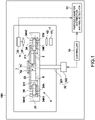
FIG. 1 is a diagram schematically illustrating a configuration of a centrifugal sedimentation-type particle diameter distribution measurement device according to an embodiment of the present invention. -
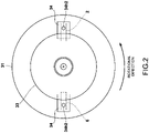
FIG. 2 is a plan view of a cell holding body to which a cover of the embodiment is attached. -
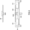
FIG. 3 is a cross-sectional view of the cell holding body and the cover of the embodiment. -
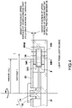
FIG. 4 is a cross-sectional view of a positional relationship between the cover and an optical path of the embodiment. -
- 100
- centrifugal sedimentation-type particle diameter distribution measurement device
- 2
- measurement cell
- 31
- cell holding body
- 311
- cell concave part
- 312
- cover concave part
- 33
- cover
- 34
- cell protecting member
- 34h1
- light passage aperture
- 34h2
- light passage aperture
- 41
- light source
- 51
- photodetector
- 6
- reference cell
- The following describes a centrifugal sedimentation-type particle diameter distribution measurement device according to an embodiment of the present invention with reference to the accompanying drawings.
- As illustrated in
FIG. 1 , a centrifugal sedimentation-type particle diameterdistribution measurement device 100 of the present embodiment includes ameasurement cell 2 that houses a sample suspension containing a measurement sample and a dispersion medium (e.g., water), acell rotation mechanism 3 that rotates themeasurement cell 2, and alight irradiation section 4 and alight detection section 5 that are optical measurement systems between which a rotation passage region is provided in which themeasurement cell 2 is rotated by thecell rotation mechanism 3. The rotation passage region is an annular region through which themeasurement cell 2 passes due to thecell rotation mechanism 3, and is provided as partially interposed between thelight irradiation section 4 and thelight detection section 5 in a circumferential direction. - The
measurement cell 2 is, for example, a rectangular cell formed from a translucent resin material. Areference cell 6 is also provided in the present embodiment, and water is housed as a dispersion medium in thereference cell 6. - The
cell rotation mechanism 3 includes acell holding body 31 to which themeasurement cell 2 and thereference cell 6 are detachably attached, and arotation section 32 that rotates thecell holding body 31. - The
cell holding body 31 is circular in plan view (refer toFIG. 2 ), and the center thereof is the center of rotation by therotation section 32. In the present embodiment, thecell holding body 31 is disk-shaped. Themeasurement cell 2 and thereference cell 6 are attached to thecell holding body 31 such that the center of rotation of thecell holding body 31 is interposed therebetween. In addition, as particularly illustrated inFIG. 3 , an attachmentconcave part 311 corresponding to a cell shape is formed in thecell holding body 31, and thecells concave part 311. Thecell holding body 31 is made of metal. - As illustrated in
FIG. 1 and the like, acover 33 for preventing themeasurement cell 2 and thereference cell 6 from being unexpectedly detached during rotation is provided on the upper surface of thecell holding body 31. Thecover 33 is circular in plan view (refer toFIG. 2 ), and is concentrically attached to thecell holding body 31. Thecover 33 of the present embodiment is disk-shaped. - The
cover 33 is fixed to thecell holding body 31 by ascrew structure 7. The screw structure includes amale screw portion 71 provided at the center of one of thecell holding body 31 and thecover 33 and afemale screw portion 72 provided at the center of the other of thecell holding body 31 and thecover 33. Thecover 33 is then fixed to thecell holding body 31 by screwing thefemale screw portion 72 into themale screw portion 71. - Furthermore, a
cell protecting member 34 is provided in thecell holding body 31. Thecell protecting member 34 is interposed between theholder 31 and thecells cells cells cell protecting member 34 is made of the same resin as themeasurement cell 2, for example. Thecell protecting member 34 can be removed from thecell holding body 31 together with thecells - As illustrated in
FIG. 1 , therotation section 32 includes arotating shaft 321 connected to the center of the lower surface of thecell holding body 31, and amotor 322 that rotates therotating shaft 321. The rotation speed of themotor 322 is controlled by acontroller 10. Therotating shaft 321 may be integrated with thecell holding body 31 or may be formed separately. Also, therotating shaft 321 may be formed as one member or may be formed by connecting a plurality of members. - As illustrated in
FIG. 1 , thelight irradiation section 4 is provided below the rotation passage region (cell holding body 31) of thecells light irradiation section 4 of the present embodiment includes alight source 41 such as an LED, for example, and acondenser lens 42 that condenses light emitted from thelight source 41. Light emitted by thelight irradiation section 4 passes through alight passage aperture 31h formed in thecell holding body 31 and a light passage aperture 34h1 formed in thecell protecting member 34, and is irradiated into themeasurement cell 2 or thereference cell 6. The light passage apertures 34h1 and 34h2 of thecell protecting member 34 are formed so as to coincide with thelight passage aperture 31h of the cell holding body 31 (the central axes thereof coincide with each other) in a state in which thecell holding body 31 rotates and thecell protecting member 34 receives centrifugal force. - As illustrated in
FIG. 1 , thelight detection section 5 is provided above the rotation passage region (cell holding body 31) of thecells light detection section 5 of the present embodiment includes aphotodetector 51 and acondenser lens 52 that condenses light detected by thephotodetector 51. The light detected by thelight detection section 5 passes through thecells cell protecting member 34, and is condensed by thecondenser lens 52. - A light intensity signal obtained by the
photodetector 51 is acquired by a particle diameterdistribution arithmetic section 11, and particle diameter distribution data is calculated by the particle diameterdistribution arithmetic section 11. The particle diameterdistribution arithmetic section 11 converts the light intensity signal into an absorbance, and calculates the particle diameter distribution data from this temporal change. The particle diameter distribution data is displayed on a display by an unillustrated display section. The particle diameterdistribution arithmetic section 11 includes thecontroller 10 and a computer with elements such as a central processing unit (CPU), memory, an input/output interface, and an analog-to-digital (AD) converter. - Finally, in the centrifugal sedimentation-type particle diameter
distribution measurement device 100 of the present embodiment as illustrated inFIGS. 2 and4 , the rotation passage region of thecover 33 is located inside the optical path of light passing between thelight source 41 and thephotodetector 51. - Specifically, as illustrated in
FIG. 4 , a radius r of the cover 33 (distance from the rotation center of therotation section 32 to the outer peripheral edge of the cover 33) is configured to be smaller than a distance L from the rotation center of therotation section 32 to the optical path of the light. Through this configuration, thecover 33 does not have a passage aperture through which light passes. - The
cover 33 prevents thecells cell holding body 31, and is configured to partially cover the inner radial side of themeasurement cell 2 and thereference cell 6 in a state of attachment to thecell holding body 31. In the present embodiment, thecover 33 is configured to also partially cover thecell protecting member 34 that protects thecells cell protecting member 34. As a result, thecover 33 also prevents thecell protecting member 34 from flying out of thecell holding body 31. In addition, thecover 33 has a shape that covers the cellconcave part 311 in a state of attachment to thecell holding body 31, and can reduce unevenness in the upper surface of thecell holding body 31, thereby reducing windage loss and noise due to unevenness during rotation. - As illustrated in
FIG. 3 , a coverconcave part 312 for housing thecover 33 is formed in the upper surface of thecell holding body 31 in addition to the attachment concave part 311 (cell concave part 311). The coverconcave part 312 is formed coaxially with the rotation center of therotation section 32. Through the above, thecover 33 can be easily positioned on thecell holding body 31. The depth of the coverconcave part 312 is a depth at which a step between the upper surface of thecover 33 and the upper surface of thecell holding body 31 is small. In the present embodiment as illustrated inFIG. 4 , since thecover 33 is configured to partially cover thecell protecting member 34, aconcave part 341 is also formed in thecell protecting member 34 so as not to make contact with thecover 33. Since thecell protecting member 34 is configured not to make contact with thecover 33, thecell protecting member 34 moves radially outward when receiving centrifugal force during rotation of the cell holding body, and the light passage apertures 34h1 and 34h2 of thecell protecting member 34 and thelight passage aperture 31h of thecell holding body 31 coincide with each other. Specifically, thecover 33 covers thecell protecting member 34 with a gap in a rotation axial direction of thecell holding body 31. The gap in the rotation axial direction is formed due to the upper surface of the coverconcave part 312 that makes contact with the lower surface of thecover 33 being configured to be higher than the upper surface of theconcave part 341 of thecell protecting member 34 attached to the attachmentconcave part 311. That is, the gap in the rotation axial direction is formed between the lower surface of thecover 33 and the upper surface of theconcave part 341 of thecell protecting member 34. In addition, since thecell protecting member 34 moves radially outward from thecell holding body 31 when receiving centrifugal force, a gap also opens in a radial direction between the outer peripheral surface of thecover 33 and the inner surface of theconcave part 341 of thecell protecting member 34. Although the centrifugal load applied to themeasurement cell 2 is transmitted to thecell holding body 31 via thecell protecting member 34, stress generated in thecell holding body 31 can be reduced by employing a structure in which thecell protecting member 34 and thecell holding body 31 make surface contact with each other. - According to the centrifugal sedimentation-type particle diameter
distribution measurement device 100 of the present embodiment, since the rotation passage region of thecover 33 is located inside the optical path of the light passing between thelight source 41 and thephotodetector 51, it is not necessary to form a passage aperture that allows light to pass through thecover 33, and alignment of passage apertures as in the related art becomes unnecessary. As a result, work of attaching thecover 33 to thecell holding body 31 when exchanging cells or the like can be facilitated. In the present embodiment, thecover 33 can be attached by simply screwing the female screw portion of thecover 33 into the male screw portion of thecell holding body 31 without worrying about the attachment position of thecover 33 in the circumferential direction with respect to thecell holding body 31. - It should be noted that the present invention is not limited to the above embodiment.
- For example, the
cover 33 of the above embodiment need not have a circular shape in plan view as long as unevenness of the upper surface of thecell holding body 31 is reduced to reduce windage loss. Even in this case, the rotation passage region of thecover 33 is configured to be located inside the optical path of the light passing between thelight source 41 and thephotodetector 51. - Furthermore, although the light passage apertures 34h1 and 34h2 are formed in the
cell protecting member 34, it is conceivable for thecell protecting member 34 to be configured to protect portions of thecells cell protecting member 34, for example. - In the above embodiment, the
measurement cell 2 is irradiated with light and transmitted light is detected. However, when an isotope sample or a self-luminous sample is housed in themeasurement cell 2, the light irradiation section may not be provided. In this case, the rotation passage region of thecover 33 is configured to be located inside the optical path of the light from themeasurement cell 2 to thephotodetector 51. - In addition, various modifications and combinations of the embodiment may be made without departing from the gist of the present invention.
- According to the present invention, a centrifugal sedimentation-type particle diameter distribution measurement device can be provided which facilitates work of attaching a cover to a cell holding body when exchanging cells or the like.
Claims (7)
- A centrifugal sedimentation-type particle diameter distribution measurement device comprising:a cell holding body configured to hold a measurement cell housing a measurement sample and a dispersion medium;a cover attached to the cell holding body so as to cover the measurement cell;a rotation section configured to rotate the cell holding body and apply centrifugal force to the measurement cell;a light source provided on one side of a rotation passage region of the measurement cell and configured to irradiate the cell with light;a photodetector provided on another side of the rotation passage region of the measurement cell and configured to detect light transmitted through the cell; anda particle diameter distribution arithmetic section configured to acquire a light intensity signal from the photodetector and calculate a particle diameter distribution,wherein the rotation passage region of the cover is located inside an optical path of light passing between the light source and the photodetector.
- The centrifugal sedimentation-type particle diameter distribution measurement device according to claim 1, wherein,the cell holding body has a circular shape in plan view, and a center thereof serves as a rotation center of the rotation section, andthe cover has a circular shape in plan view, and is attached concentrically to the cell holding body.
- The centrifugal sedimentation-type particle diameter distribution measurement device according to claim 2, whereinthe cell holding body holds the measurement cell and a reference cell housing a reference sample such that a rotation center of the cell holding body is interposed between the measurement cell and the reference cell, andthe cover covers the measurement cell and the reference cell.
- The centrifugal sedimentation-type particle diameter distribution measurement device according to any one of claims 1 to 3, wherein a cell concave part that houses the measurement cell and a cover concave part that houses the cover are formed on one surface of the cell holding body.
- The centrifugal sedimentation-type particle diameter distribution measurement device according to any one of claims 1 to 4, further comprising a cell protecting member interposed between the cell holding body and the measurement cell and configured to disperse centrifugal force applied to the measurement cell to prevent breakage of the measurement cell.
- The centrifugal sedimentation-type particle diameter distribution measurement device according to claim 5, wherein a light transmission portion is formed in the cell protecting member through which light is transmitted from the light source to the photodetector.
- The centrifugal sedimentation-type particle diameter distribution measurement device according to claim 5or 6, wherein the cover covers the cell protecting member with a gap in a rotation axial direction of the cell holding body.
Applications Claiming Priority (2)
| Application Number | Priority Date | Filing Date | Title |
|---|---|---|---|
| JP2020001365 | 2020-01-08 | ||
| PCT/JP2020/045161 WO2021140797A1 (en) | 2020-01-08 | 2020-12-04 | Centrifugal sedimentation-type particle diameter distribution measurement device |
Publications (3)
| Publication Number | Publication Date |
|---|---|
| EP4089393A1 true EP4089393A1 (en) | 2022-11-16 |
| EP4089393A4 EP4089393A4 (en) | 2024-01-17 |
| EP4089393B1 EP4089393B1 (en) | 2025-11-05 |
Family
ID=76788574
Family Applications (1)
| Application Number | Title | Priority Date | Filing Date |
|---|---|---|---|
| EP20912815.6A Active EP4089393B1 (en) | 2020-01-08 | 2020-12-04 | Centrifugal sedimentation-type particle diameter distribution measurement device |
Country Status (4)
| Country | Link |
|---|---|
| US (1) | US20230049821A1 (en) |
| EP (1) | EP4089393B1 (en) |
| JP (1) | JP7503079B2 (en) |
| WO (1) | WO2021140797A1 (en) |
Family Cites Families (15)
| Publication number | Priority date | Publication date | Assignee | Title |
|---|---|---|---|---|
| US3967828A (en) * | 1975-03-03 | 1976-07-06 | The Wurlitzer Company | Record selector mechanism for a phonograph system |
| GB1533586A (en) * | 1976-05-12 | 1978-11-29 | Groves M | Centrifuges |
| JPS5653895Y2 (en) * | 1979-02-02 | 1981-12-15 | ||
| JPS57211042A (en) * | 1981-06-20 | 1982-12-24 | Horiba Ltd | Cell holder in rotary disc |
| US4742718A (en) * | 1985-10-29 | 1988-05-10 | Onoda Cement Company, Ltd. | Apparatus for measuring particle-size distribution |
| JPS62111657U (en) * | 1986-01-07 | 1987-07-16 | ||
| JPH0387636A (en) * | 1989-08-31 | 1991-04-12 | Seishin Kigyo:Kk | Method and instrument for measuring viscosity distribution of centrifugal sedimentation |
| US5208791A (en) * | 1990-02-16 | 1993-05-04 | Pioneer Electronic Corporation | System for recovering a CD in a CD player having a magazine containing a plurality of disks |
| JPH056365U (en) * | 1991-07-11 | 1993-01-29 | 株式会社リケン | Gas detection element |
| JPH056353U (en) | 1991-07-11 | 1993-01-29 | 株式会社堀場製作所 | Rotating disk for particle size distribution measurement |
| JP3801039B2 (en) * | 2001-12-10 | 2006-07-26 | ヤマハ株式会社 | Disc changer device |
| US20040016686A1 (en) * | 2002-07-24 | 2004-01-29 | Wyatt Philip J. | Absolute measurement centrifuge |
| US7294513B2 (en) * | 2002-07-24 | 2007-11-13 | Wyatt Technology Corporation | Method and apparatus for characterizing solutions of small particles |
| KR100895395B1 (en) * | 2007-12-28 | 2009-04-30 | 광주과학기술원 | Cell Separator Using Centrifugal Force and Genetics |
| EP2957890A1 (en) * | 2014-06-16 | 2015-12-23 | Roche Diagnostics GmbH | Cartridge with a rotatable lid |
-
2020
- 2020-12-04 WO PCT/JP2020/045161 patent/WO2021140797A1/en not_active Ceased
- 2020-12-04 EP EP20912815.6A patent/EP4089393B1/en active Active
- 2020-12-04 US US17/791,141 patent/US20230049821A1/en active Pending
- 2020-12-04 JP JP2021569766A patent/JP7503079B2/en active Active
Also Published As
| Publication number | Publication date |
|---|---|
| WO2021140797A1 (en) | 2021-07-15 |
| EP4089393B1 (en) | 2025-11-05 |
| US20230049821A1 (en) | 2023-02-16 |
| JPWO2021140797A1 (en) | 2021-07-15 |
| EP4089393A4 (en) | 2024-01-17 |
| JP7503079B2 (en) | 2024-06-19 |
Similar Documents
| Publication | Publication Date | Title |
|---|---|---|
| US9503618B2 (en) | Camera system for monitoring a space area | |
| EP3026414A1 (en) | Testing device for thin-walled large bearing | |
| US8164828B2 (en) | Observable centrifugal apparatus and observation apparatus | |
| JP4901333B2 (en) | Microchip inspection device | |
| US9243976B2 (en) | Sensor bearing assembly with cover mounted sensor | |
| EP4089393B1 (en) | Centrifugal sedimentation-type particle diameter distribution measurement device | |
| US20160377505A1 (en) | Testing device for thin-walled large-sized bearing | |
| US20190146176A1 (en) | Inclination adjusting mechanism | |
| EP3557297A1 (en) | Solid immersion lens unit and semiconductor detector device | |
| US10866257B2 (en) | Wheel hub bearing provided with a device for measuring the rotational speed | |
| US20160271616A1 (en) | Grinding Device Having A Wear Disk | |
| US7076018B2 (en) | Tomography apparatus with gantry-carried component mounted to withstand centrifugal forces | |
| RU2542636C1 (en) | Method for centring lens in holder and holder therefor | |
| CN105358989A (en) | A sensor-bearing unit, a mechanical system comprising at least one such unit and implementing methods | |
| US8617060B2 (en) | Endoscope light source apparatus and endoscope system | |
| EP3869180B1 (en) | Centrifugal sedimentation-type particle size distribution measurement device | |
| JP2010249519A (en) | Member and assembly for fixing read plate, and signal detecting device, as well as rotary encoder | |
| CN1825123B (en) | Protective device for speed sensor | |
| US20210063237A1 (en) | Vibration detection instrument assembly and method of assembling a vibration detection instrument assembly | |
| EP1529709A1 (en) | Bearing assembly for a railway axle | |
| CN107052985B (en) | Plane grinding device | |
| KR102795217B1 (en) | Supplying device for test tube and label attaching system including the same | |
| JP4133251B2 (en) | Optical rotation measuring device | |
| CN218382372U (en) | Spectrum detection device and spectrum detection equipment | |
| JP2025080773A (en) | Inserts, centrifuges, analytical equipment |
Legal Events
| Date | Code | Title | Description |
|---|---|---|---|
| STAA | Information on the status of an ep patent application or granted ep patent |
Free format text: STATUS: THE INTERNATIONAL PUBLICATION HAS BEEN MADE |
|
| PUAI | Public reference made under article 153(3) epc to a published international application that has entered the european phase |
Free format text: ORIGINAL CODE: 0009012 |
|
| STAA | Information on the status of an ep patent application or granted ep patent |
Free format text: STATUS: REQUEST FOR EXAMINATION WAS MADE |
|
| 17P | Request for examination filed |
Effective date: 20220726 |
|
| AK | Designated contracting states |
Kind code of ref document: A1 Designated state(s): AL AT BE BG CH CY CZ DE DK EE ES FI FR GB GR HR HU IE IS IT LI LT LU LV MC MK MT NL NO PL PT RO RS SE SI SK SM TR |
|
| DAV | Request for validation of the european patent (deleted) | ||
| DAX | Request for extension of the european patent (deleted) | ||
| A4 | Supplementary search report drawn up and despatched |
Effective date: 20231219 |
|
| RIC1 | Information provided on ipc code assigned before grant |
Ipc: G01N 15/00 20060101ALN20231213BHEP Ipc: G01N 15/04 20060101ALI20231213BHEP Ipc: G01N 15/02 20060101AFI20231213BHEP |
|
| REG | Reference to a national code |
Ref legal event code: R079 Ipc: G01N0015020500 Ref country code: DE Ref legal event code: R079 Ref document number: 602020061910 Country of ref document: DE Free format text: PREVIOUS MAIN CLASS: G01N0015020000 Ipc: G01N0015020500 |
|
| GRAP | Despatch of communication of intention to grant a patent |
Free format text: ORIGINAL CODE: EPIDOSNIGR1 |
|
| STAA | Information on the status of an ep patent application or granted ep patent |
Free format text: STATUS: GRANT OF PATENT IS INTENDED |
|
| RIC1 | Information provided on ipc code assigned before grant |
Ipc: G01N 15/0205 20240101AFI20250612BHEP Ipc: G01N 15/04 20060101ALI20250612BHEP Ipc: G01N 15/00 20060101ALN20250612BHEP |
|
| RIC1 | Information provided on ipc code assigned before grant |
Ipc: G01N 15/0205 20240101AFI20250613BHEP Ipc: G01N 15/04 20060101ALI20250613BHEP Ipc: G01N 15/00 20060101ALN20250613BHEP |
|
| INTG | Intention to grant announced |
Effective date: 20250626 |
|
| GRAS | Grant fee paid |
Free format text: ORIGINAL CODE: EPIDOSNIGR3 |
|
| GRAA | (expected) grant |
Free format text: ORIGINAL CODE: 0009210 |
|
| STAA | Information on the status of an ep patent application or granted ep patent |
Free format text: STATUS: THE PATENT HAS BEEN GRANTED |
|
| P01 | Opt-out of the competence of the unified patent court (upc) registered |
Free format text: CASE NUMBER: UPC_APP_6331_4089393/2025 Effective date: 20250909 |
|
| AK | Designated contracting states |
Kind code of ref document: B1 Designated state(s): AL AT BE BG CH CY CZ DE DK EE ES FI FR GB GR HR HU IE IS IT LI LT LU LV MC MK MT NL NO PL PT RO RS SE SI SK SM TR |
|
| REG | Reference to a national code |
Ref country code: CH Ref legal event code: F10 Free format text: ST27 STATUS EVENT CODE: U-0-0-F10-F00 (AS PROVIDED BY THE NATIONAL OFFICE) Effective date: 20251105 Ref country code: GB Ref legal event code: FG4D |
|
| REG | Reference to a national code |
Ref country code: DE Ref legal event code: R096 Ref document number: 602020061910 Country of ref document: DE |
|
| REG | Reference to a national code |
Ref country code: IE Ref legal event code: FG4D |
|
| PGFP | Annual fee paid to national office [announced via postgrant information from national office to epo] |
Ref country code: GB Payment date: 20251219 Year of fee payment: 6 |
|
| REG | Reference to a national code |
Ref country code: NL Ref legal event code: MP Effective date: 20251105 |
|
| PG25 | Lapsed in a contracting state [announced via postgrant information from national office to epo] |
Ref country code: ES Free format text: LAPSE BECAUSE OF FAILURE TO SUBMIT A TRANSLATION OF THE DESCRIPTION OR TO PAY THE FEE WITHIN THE PRESCRIBED TIME-LIMIT Effective date: 20251105 |
|
| REG | Reference to a national code |
Ref country code: LT Ref legal event code: MG9D |
|
| PG25 | Lapsed in a contracting state [announced via postgrant information from national office to epo] |
Ref country code: NO Free format text: LAPSE BECAUSE OF FAILURE TO SUBMIT A TRANSLATION OF THE DESCRIPTION OR TO PAY THE FEE WITHIN THE PRESCRIBED TIME-LIMIT Effective date: 20260205 |
|
| PGFP | Annual fee paid to national office [announced via postgrant information from national office to epo] |
Ref country code: DE Payment date: 20251230 Year of fee payment: 6 |
|
| PG25 | Lapsed in a contracting state [announced via postgrant information from national office to epo] |
Ref country code: FI Free format text: LAPSE BECAUSE OF FAILURE TO SUBMIT A TRANSLATION OF THE DESCRIPTION OR TO PAY THE FEE WITHIN THE PRESCRIBED TIME-LIMIT Effective date: 20251105 Ref country code: HR Free format text: LAPSE BECAUSE OF FAILURE TO SUBMIT A TRANSLATION OF THE DESCRIPTION OR TO PAY THE FEE WITHIN THE PRESCRIBED TIME-LIMIT Effective date: 20251105 Ref country code: AT Free format text: LAPSE BECAUSE OF FAILURE TO SUBMIT A TRANSLATION OF THE DESCRIPTION OR TO PAY THE FEE WITHIN THE PRESCRIBED TIME-LIMIT Effective date: 20251105 |
|
| REG | Reference to a national code |
Ref country code: AT Ref legal event code: MK05 Ref document number: 1854835 Country of ref document: AT Kind code of ref document: T Effective date: 20251105 |
|
| PG25 | Lapsed in a contracting state [announced via postgrant information from national office to epo] |
Ref country code: NL Free format text: LAPSE BECAUSE OF FAILURE TO SUBMIT A TRANSLATION OF THE DESCRIPTION OR TO PAY THE FEE WITHIN THE PRESCRIBED TIME-LIMIT Effective date: 20251105 |
|
| PG25 | Lapsed in a contracting state [announced via postgrant information from national office to epo] |
Ref country code: RS Free format text: LAPSE BECAUSE OF FAILURE TO SUBMIT A TRANSLATION OF THE DESCRIPTION OR TO PAY THE FEE WITHIN THE PRESCRIBED TIME-LIMIT Effective date: 20260205 |
|
| PG25 | Lapsed in a contracting state [announced via postgrant information from national office to epo] |
Ref country code: IS Free format text: LAPSE BECAUSE OF FAILURE TO SUBMIT A TRANSLATION OF THE DESCRIPTION OR TO PAY THE FEE WITHIN THE PRESCRIBED TIME-LIMIT Effective date: 20260305 |
|
| PG25 | Lapsed in a contracting state [announced via postgrant information from national office to epo] |
Ref country code: PT Free format text: LAPSE BECAUSE OF FAILURE TO SUBMIT A TRANSLATION OF THE DESCRIPTION OR TO PAY THE FEE WITHIN THE PRESCRIBED TIME-LIMIT Effective date: 20260305 |
|
| PG25 | Lapsed in a contracting state [announced via postgrant information from national office to epo] |
Ref country code: PL Free format text: LAPSE BECAUSE OF FAILURE TO SUBMIT A TRANSLATION OF THE DESCRIPTION OR TO PAY THE FEE WITHIN THE PRESCRIBED TIME-LIMIT Effective date: 20251105 |
|
| PG25 | Lapsed in a contracting state [announced via postgrant information from national office to epo] |
Ref country code: LV Free format text: LAPSE BECAUSE OF FAILURE TO SUBMIT A TRANSLATION OF THE DESCRIPTION OR TO PAY THE FEE WITHIN THE PRESCRIBED TIME-LIMIT Effective date: 20251105 |
|
| PG25 | Lapsed in a contracting state [announced via postgrant information from national office to epo] |
Ref country code: BG Free format text: LAPSE BECAUSE OF FAILURE TO SUBMIT A TRANSLATION OF THE DESCRIPTION OR TO PAY THE FEE WITHIN THE PRESCRIBED TIME-LIMIT Effective date: 20251105 |