EP4089390A1 - State monitoring device and wind power generation device provided with state monitoring device - Google Patents
State monitoring device and wind power generation device provided with state monitoring device Download PDFInfo
- Publication number
- EP4089390A1 EP4089390A1 EP21738941.0A EP21738941A EP4089390A1 EP 4089390 A1 EP4089390 A1 EP 4089390A1 EP 21738941 A EP21738941 A EP 21738941A EP 4089390 A1 EP4089390 A1 EP 4089390A1
- Authority
- EP
- European Patent Office
- Prior art keywords
- trigger signal
- measurement process
- received
- measurement
- priority
- Prior art date
- Legal status (The legal status is an assumption and is not a legal conclusion. Google has not performed a legal analysis and makes no representation as to the accuracy of the status listed.)
- Granted
Links
Images



Classifications
-
- F—MECHANICAL ENGINEERING; LIGHTING; HEATING; WEAPONS; BLASTING
- F03—MACHINES OR ENGINES FOR LIQUIDS; WIND, SPRING, OR WEIGHT MOTORS; PRODUCING MECHANICAL POWER OR A REACTIVE PROPULSIVE THRUST, NOT OTHERWISE PROVIDED FOR
- F03D—WIND MOTORS
- F03D17/00—Monitoring or testing of wind motors, e.g. diagnostics
- F03D17/009—Monitoring or testing of wind motors, e.g. diagnostics characterised by the purpose
- F03D17/013—Monitoring or testing of wind motors, e.g. diagnostics characterised by the purpose for detecting abnormalities or damage
-
- F—MECHANICAL ENGINEERING; LIGHTING; HEATING; WEAPONS; BLASTING
- F03—MACHINES OR ENGINES FOR LIQUIDS; WIND, SPRING, OR WEIGHT MOTORS; PRODUCING MECHANICAL POWER OR A REACTIVE PROPULSIVE THRUST, NOT OTHERWISE PROVIDED FOR
- F03D—WIND MOTORS
- F03D17/00—Monitoring or testing of wind motors, e.g. diagnostics
- F03D17/027—Monitoring or testing of wind motors, e.g. diagnostics characterised by the component being monitored or tested
- F03D17/032—Bearings
-
- G—PHYSICS
- G01—MEASURING; TESTING
- G01M—TESTING STATIC OR DYNAMIC BALANCE OF MACHINES OR STRUCTURES; TESTING OF STRUCTURES OR APPARATUS, NOT OTHERWISE PROVIDED FOR
- G01M13/00—Testing of machine parts
- G01M13/04—Bearings
- G01M13/045—Acoustic or vibration analysis
-
- F—MECHANICAL ENGINEERING; LIGHTING; HEATING; WEAPONS; BLASTING
- F03—MACHINES OR ENGINES FOR LIQUIDS; WIND, SPRING, OR WEIGHT MOTORS; PRODUCING MECHANICAL POWER OR A REACTIVE PROPULSIVE THRUST, NOT OTHERWISE PROVIDED FOR
- F03D—WIND MOTORS
- F03D17/00—Monitoring or testing of wind motors, e.g. diagnostics
- F03D17/009—Monitoring or testing of wind motors, e.g. diagnostics characterised by the purpose
- F03D17/015—Monitoring or testing of wind motors, e.g. diagnostics characterised by the purpose for monitoring vibrations
-
- F—MECHANICAL ENGINEERING; LIGHTING; HEATING; WEAPONS; BLASTING
- F05—INDEXING SCHEMES RELATING TO ENGINES OR PUMPS IN VARIOUS SUBCLASSES OF CLASSES F01-F04
- F05B—INDEXING SCHEME RELATING TO WIND, SPRING, WEIGHT, INERTIA OR LIKE MOTORS, TO MACHINES OR ENGINES FOR LIQUIDS COVERED BY SUBCLASSES F03B, F03D AND F03G
- F05B2240/00—Components
- F05B2240/50—Bearings
-
- F—MECHANICAL ENGINEERING; LIGHTING; HEATING; WEAPONS; BLASTING
- F05—INDEXING SCHEMES RELATING TO ENGINES OR PUMPS IN VARIOUS SUBCLASSES OF CLASSES F01-F04
- F05B—INDEXING SCHEME RELATING TO WIND, SPRING, WEIGHT, INERTIA OR LIKE MOTORS, TO MACHINES OR ENGINES FOR LIQUIDS COVERED BY SUBCLASSES F03B, F03D AND F03G
- F05B2270/00—Control
- F05B2270/30—Control parameters, e.g. input parameters
- F05B2270/334—Vibration measurements
-
- F—MECHANICAL ENGINEERING; LIGHTING; HEATING; WEAPONS; BLASTING
- F16—ENGINEERING ELEMENTS AND UNITS; GENERAL MEASURES FOR PRODUCING AND MAINTAINING EFFECTIVE FUNCTIONING OF MACHINES OR INSTALLATIONS; THERMAL INSULATION IN GENERAL
- F16C—SHAFTS; FLEXIBLE SHAFTS; ELEMENTS OR CRANKSHAFT MECHANISMS; ROTARY BODIES OTHER THAN GEARING ELEMENTS; BEARINGS
- F16C2322/00—Apparatus used in shaping articles
-
- F—MECHANICAL ENGINEERING; LIGHTING; HEATING; WEAPONS; BLASTING
- F16—ENGINEERING ELEMENTS AND UNITS; GENERAL MEASURES FOR PRODUCING AND MAINTAINING EFFECTIVE FUNCTIONING OF MACHINES OR INSTALLATIONS; THERMAL INSULATION IN GENERAL
- F16C—SHAFTS; FLEXIBLE SHAFTS; ELEMENTS OR CRANKSHAFT MECHANISMS; ROTARY BODIES OTHER THAN GEARING ELEMENTS; BEARINGS
- F16C2360/00—Engines or pumps
- F16C2360/31—Wind motors
-
- Y—GENERAL TAGGING OF NEW TECHNOLOGICAL DEVELOPMENTS; GENERAL TAGGING OF CROSS-SECTIONAL TECHNOLOGIES SPANNING OVER SEVERAL SECTIONS OF THE IPC; TECHNICAL SUBJECTS COVERED BY FORMER USPC CROSS-REFERENCE ART COLLECTIONS [XRACs] AND DIGESTS
- Y02—TECHNOLOGIES OR APPLICATIONS FOR MITIGATION OR ADAPTATION AGAINST CLIMATE CHANGE
- Y02E—REDUCTION OF GREENHOUSE GAS [GHG] EMISSIONS, RELATED TO ENERGY GENERATION, TRANSMISSION OR DISTRIBUTION
- Y02E10/00—Energy generation through renewable energy sources
- Y02E10/70—Wind energy
- Y02E10/72—Wind turbines with rotation axis in wind direction
Definitions
- the present invention relates to a condition monitoring device that executes a measurement process for monitoring a condition of a mechanical component in response to reception of a trigger signal, and more particularly to a condition monitoring device for a wind turbine generation apparatus.
- a wind turbine generation apparatus In a wind turbine generation apparatus, the main shaft connected to blades receiving wind is rotated, and after the gearbox increases the speed of rotation of the main shaft, the rotor of the generator is rotated to generate electric power.
- Each of the rotation axes of the main shaft, the gear box, and the generator is rotatably supported by a rolling bearing.
- a condition monitoring system is known that diagnoses a condition of such a bearing using measurement data by a vibration sensor fixed to the bearing.
- condition monitoring systems for wind turbine generation apparatuses include a condition monitoring device that executes a measurement process of performing measurement with a vibration sensor in response to reception of a trigger signal (for example, see Japanese Patent Laying-Open No. 2019-52964 (PTL 1)).
- a trigger source producing a trigger signal is provided outside or inside a condition monitoring device.
- the trigger source outputs a fixed time trigger signal to the condition monitoring device on a specified time.
- the condition monitoring device executes a measurement process corresponding to the fixed time trigger signal (hereinafter also referred to as "fixed time measurement process") for a certain time in response to reception of the fixed time trigger signal from the trigger source.
- the fixed time measurement process Since the fixed time measurement process is repeatedly executed every specified time, a process involving a smaller data volume is executed in the fixed time measurement process. Furthermore, the operation is performed with a smaller measurement data volume, for example, such that measurement is not carried out in an idle state.
- the event measurement process is executed abruptly and yields measurement data to be used for diagnosis of the wind turbine generation apparatus. Therefore, a process involving a larger data volume is executed in order to obtain more detailed data.
- the content of the event measurement process differs from the content of the fixed time measurement process, and it can be said that the event measurement process has a higher priority than the fixed time measurement process.
- the condition monitoring device receives an event trigger signal while executing the fixed time measurement process
- the event measurement process is started after the fixed time measurement process being executed is completed.
- the start timing of the event measurement process with a high priority may be delayed.
- an additional processor such as a central processing unit (CPU) and a memory
- CPU central processing unit
- a memory for handling the parallel process is required, and it is sometimes difficult to reserve a space for installing an additional processor in a compact wind turbine generation apparatus.
- the present disclosure is made to solve the problem above and aimed to suppress delay in the start timing of a measurement process with a high priority without installing an additional processor.
- the measurement processing unit suspends the measurement process being executed and starts a measurement process corresponding to the received trigger signal.
- This configuration suppresses delay in the start timing of a measurement process having a higher priority due to a measurement process having a lower priority being executed. Furthermore, since the measurement process being executed with a lower priority is suspended, there is no need for installing an additional processor for handling the parallel process. As a result, delay in the start timing of a measurement process having a higher priority can be suppressed without installing an additional processor. As a result, data is measured at a timing as required, and the presence or absence of abnormality of an apparatus that is a measurement target can be determined accurately based on the measured data.
- Fig. 1 is a diagram schematically showing a configuration of a wind turbine generation apparatus 10 to which a condition monitoring device 80 according to the present embodiment is applied.
- Wind turbine generation apparatus 10 includes a main shaft 20, a blade 30, a gearbox 40, a generator 50, a main shaft bearing (hereinafter simply referred to as "bearing") 60, a vibration sensor 70, and a condition monitoring device 80.
- Gearbox 40, generator 50, bearing 60, vibration sensor 70, and condition monitoring device 80 are stored in a nacelle 90.
- Nacelle 90 is supported by a tower 100.
- Main shaft 20 extends into nacelle 90 to be connected to the input shaft of gearbox 40 and is rotatably supported by bearing 60. Main shaft 20 then transmits rotational torque generated by blade 30 receiving wind power to the input shaft of gearbox 40. Blade 30 is provided at the tip end of main shaft 20 and converts wind power into rotational torque to be transmitted to main shaft 20.
- Bearing 60 is fixed in nacelle 90 and rotatably supports main shaft 20.
- Bearing 60 is configured with a rolling bearing, for example, configured with a spherical roller bearing, a tapered roller bearing, a cylindrical roller bearing, or a ball bearing. These bearings may be a single row or a double row.
- Gearbox 40 is provided between main shaft 20 and generator 50 to increase the rotational speed of main shaft 20 for output to generator 50.
- gearbox 40 is configured with a gear speed-increasing mechanism including a planetary gear train, an intermediate shaft, and a high speed shaft.
- a plurality of bearings rotatably supporting a plurality of shafts are also provided in gearbox 40.
- Generator 50 is connected to the output shaft of gearbox 40 to generate electric power with the rotational torque received from gearbox 40.
- Generator 50 is configured with, for example, an induction generator.
- a bearing rotatably supporting the rotor is also provided in generator 50.
- Vibration sensor 70 is fixed to bearing 60. Vibration sensor 70 measures the vibration waveform of bearing 60 and outputs the measured vibration waveform data to condition monitoring device 80. Vibration sensor 70 is configured with, for example, an acceleration sensor having a piezoelectric element.
- Condition monitoring device 80 is provided inside nacelle 90.
- Condition monitoring device 80 is connected to vibration sensor 70 and stores the detection result by vibration sensor 70 for a certain time.
- Condition monitoring device 80 then executes a measurement process using the detection result by vibration sensor 70 in response to reception of a trigger signal from an external device and transmits data obtained by the measurement process (hereinafter also referred to as "measurement data") to an external data server.
- Fig. 2 is a functional block diagram showing a functional configuration of a condition monitoring system 1 including vibration sensor 70 and condition monitoring device 80 shown in Fig. 1 .
- Condition monitoring system 1 includes an external device 200 serving as a trigger source and a data server 300, in addition to vibration sensor 70 and condition monitoring device 80 described above.
- Vibration sensor 70 and condition monitoring device 80 are provided inside nacelle 90 as described above.
- external device 200 and data server 300 are provided outside nacelle 90.
- external device 200 When a detection signal is externally input, external device 200 outputs a trigger signal corresponding to the detection signal to condition monitoring device 80 via wired communication or wireless communication.
- the detection signal input to external device 200 includes a "fixed time detection signal Da" and an “event detection signal Db".
- the "fixed time detection signal Da” is a signal indicating that a predetermined specified time has come.
- the “event detection signal Db” is a signal indicating that an abrupt event that may cause damage to wind turbine generation apparatus 10 is detected.
- the event detection signal Db includes a signal indicating that abnormal vibration is detected, a signal indicating a lightning strike is detected, a signal indicating a temperature variation exceeding a reference value is detected, a signal indicating that a wind speed change exceeding a reference value is detected, a signal indicating that a wind direction change exceeding a reference value is detected, and a signal indicating that emergency stop is detected.
- external device 200 When a fixed time detection signal Da is externally input, external device 200 outputs a "fixed time trigger signal A" corresponding to the fixed time detection signal Da to condition monitoring device 80. When an event detection signal Db is externally received, external device 200 outputs an "event trigger signal B" corresponding to the event detection signal Db to condition monitoring device 80. Examples of external device 200 include a programmable logic controller (PLC), supervisory control and data acquisition (SCADA), and a computer for measurement.
- PLC programmable logic controller
- SCADA supervisory control and data acquisition
- external device 200 may be divided into two or more.
- external device 200 is provided outside nacelle 90 in Fig. 2
- external device 200 may be provided inside nacelle 90.
- an external device having the function of outputting a fixed time trigger signal A may be provided inside nacelle 90
- an external device having the function of outputting an event trigger signal B may be provided outside nacelle 90.
- condition monitoring device 80 executes a measurement process using the detection result by vibration sensor 70 and transmits (uploads) measurement data obtained by the measurement process to data server 300.
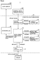
- Fig. 3 is a functional block diagram showing a functional configuration of condition monitoring device 80 in detail.
- Condition monitoring device 80 includes a trigger detecting unit 81, a trigger setting unit 82, a measurement processing unit 83, a fixed time measurement setting unit 85, an event measurement setting unit 86, a data storage unit 87, and an uploading unit 88.
- trigger detecting unit 81 Upon receiving a trigger signal from external device 200, trigger detecting unit 81 stores the time when the trigger signal is received and requests trigger setting unit 82 to set the priority and the measurement type corresponding to the received trigger signal. Trigger setting unit 82 sets the priority and the measurement type corresponding to the trigger signal received from trigger detecting unit 81 and transmits the result as a trigger setting result to trigger detecting unit 81.
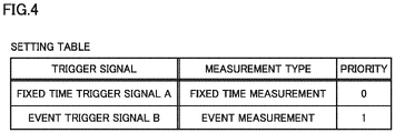
- Fig. 4 is a diagram of an exemplary setting table used to set the priority and the measurement type of a trigger signal.
- “fixed time measurement” is set as the measurement type and "0" is set as the priority for the fixed time trigger signal A.
- Event measurement is set as the measurement type and "1” is set as the priority for the event trigger signal B.
- the priority "1” is meant to be higher than the priority "0”.
- Trigger setting unit 82 refers to the setting table as shown in Fig. 4 to set the priority and the measurement type corresponding to a trigger signal received from trigger detecting unit 81 and transmits the result as a trigger setting result to trigger detecting unit 81.
- trigger detecting unit 81 upon receiving the trigger setting result from trigger setting unit 82, trigger detecting unit 81 notifies measurement processing unit 83 of the trigger setting result received from trigger setting unit 82, together with the time when the trigger signal is received.
- Measurement processing unit 83 is configured to execute a measurement process in accordance with the notification from trigger detecting unit 81.
- measurement processing unit 83 requests fixed time measurement setting unit 85 to set the process content of the fixed time measurement.
- fixed time measurement setting unit 85 sets the content of the fixed time measurement process and returns the set process content to measurement processing unit 83.
- the fixed time measurement process is set to the content "measurement data for a period until a predetermined time Ta has passed from reception of a fixed time trigger signal A is output to data server 300".
- measurement processing unit 83 requests event measurement setting unit 86 to set the content of the event measurement process.
- event measurement setting unit 86 sets the content of the event measurement process and returns the set process content to measurement processing unit 83.
- the event measurement process is set to the content "measurement data for a period until a predetermined time Tb has passed from a predetermined time before the time when the event trigger signal B is received is output to data server 300". In this way, the content of the event measurement process differs from the content of the fixed time measurement process.
- the contents of the fixed time measurement process and the event measurement process are illustrated only by way of example and are not limited to the contents described above.
- the fixed time measurement process may be a process involving a smaller data volume since it is a process that is always repeatedly carried out
- the event measurement process may be a process involving a larger data volume in order to obtain more detailed data.
- Measurement processing unit 83 reads measurement data stored in data storage unit 87 in accordance with the process content received from fixed time measurement setting unit 85 or event measurement setting unit 86 and outputs the read measurement data to uploading unit 88.
- measurement processing unit 83 requests data storage unit 87 to transmit measurement data for a period until a predetermined time Ta has passed from reception of a fixed time trigger signal A.
- measurement processing unit 83 requests data storage unit 87 to transmit measurement data for a period until a predetermined time Tb has passed from a predetermined time before an event trigger signal B is received.
- Data storage unit 87 always acquires measurement data by vibration sensor 70 and stores the acquired measurement data for a certain period (a period sufficiently longer than the predetermined times Ta and Tb), together with the measurement time. Data storage unit 87 reads measurement data for a period requested by measurement processing unit 83 from among the stored measurement data and transmits the read measurement data to measurement processing unit 83. Measurement processing unit 83 outputs the measurement data received from data storage unit 87 to uploading unit 88.
- Uploading unit 88 outputs (uploads) the measurement data received from measurement processing unit 83 to data server 300 via wired communication or wireless communication, together with the time when a trigger signal is received and the trigger setting result by trigger setting unit 82.
- Data server 300 performs a process of diagnosing a condition of wind turbine generation apparatus 10, based on the measurement data received from uploading unit 88.
- the fixed time measurement process is repeatedly executed every specified time.
- the event measurement process is executed when abrupt events such as lightning strikes, earthquakes, and wind gusts occur, and the measurement data obtained by the event measurement process is used for diagnosis of wind turbine generation apparatus 10. Therefore, it can be said that the event measurement process has a higher priority than the fixed time measurement process.
- condition monitoring device 80 sets a priority for a trigger signal received from external device 200. Specifically, as described above, the priority of a fixed time trigger signal A is set to "0", and the priority of an event trigger signal B is set to "1" higher than zero. Then, when an event trigger signal B is received and the fixed time measurement process caused by a fixed time trigger signal A having a priority "0" lower than the priority "1" of the event trigger signal B is being executed, condition monitoring device 80 halts the fixed time measurement process being executed and starts the event measurement process corresponding to the received event trigger signal B. This can suppress delay in the starting timing of an event measurement process having a higher priority.
- Fig. 5 is a flowchart showing an exemplary process in which condition monitoring device 80 executes a measurement process. This flowchart is repeatedly performed every time a predetermined condition is met (for example, at predetermined intervals). First of all, condition monitoring device 80 determines whether a trigger signal is received from external device 200 (step S10).
- condition monitoring device 80 receives a trigger signal from external device 200 (YES at step S10), condition monitoring device 80 refers to the setting table above shown in Fig. 4 and determines whether the priority of the trigger signal received this time is "1" (that is, whether the trigger signal is an event trigger signal B) (step S20).
- condition monitoring device 80 determines whether the event measurement process having the same priority "1" as the priority "1" of the event trigger signal B received this time is being executed (step S22).
- condition monitoring device 80 registers the event trigger signal B received this time (step S24). Thus, the event measurement process being executed continues as it is. Subsequently, condition monitoring device 80 skips the subsequent process and moves the process to return.
- the event trigger signal B registered at step S24 is treated as "registered trigger signal" in the next and subsequent computation cycles.
- the event measurement process corresponding to the registered trigger signal is executed successively after completion of the event measurement process being executed.
- condition monitoring device 80 determines whether the fixed time measurement process having a priority "0" lower than the priority of the event trigger signal B received this time is being executed (step S26).
- condition monitoring device 80 executes the event measurement process corresponding to the event trigger signal B received this time (step S30).
- condition monitoring device 80 suspends the fixed time measurement process being executed (step S28) and executes the event measurement process corresponding to the event trigger signal B received this time (step S30).
- condition monitoring device 80 determines whether the event measurement process having a priority "1" higher than the priority of the received fixed time trigger signal A is being executed (step S40).
- condition monitoring device 80 discards the received fixed time trigger signal A (step S46). Thus, the event measurement process having a priority "1" being executed continues.
- condition monitoring device 80 determines whether the fixed time measurement process having the same priority "0" as the priority of the received fixed time trigger signal A is being executed (step S42). If the fixed time measurement process is being executed (YES at step S42), condition monitoring device 80 discards the received fixed time trigger signal A (step S46). Thus, the fixed time measurement process having a priority "0" being executed continues.
- condition monitoring device 80 executes the fixed time measurement process corresponding to the fixed time trigger signal A received this time (step S44).
- condition monitoring device 80 determines whether the event measurement process having a priority "1" is being executed (step S11). If the event measurement process is being executed (YES at step S11), condition monitoring device 80 skips the subsequent process and moves the process to return.
- condition monitoring device 80 determines whether a registered trigger signal exists (step S12).
- the registered trigger signal is the event trigger signal B registered at step S24 in the last and preceding computation cycles. If no registered trigger signal exists (NO at step S12), condition monitoring device 80 skips the subsequent process and moves the process to return.
- condition monitoring device 80 executes the process subsequent to step S20 for the registered trigger signal. That is, since the registered trigger signal is an event trigger signal B having a priority "1", the determination by monitoring device 80 at step S20 is YES. Furthermore, since the event measurement process having a priority "1" is not being executed as determined at step S11, the determination at step S22 is NO, and the event measurement process corresponding to the registered trigger signal is executed at step S30.
- condition monitoring device 80 discards the registered trigger signal (step S32). That is, even when a plurality of registered trigger signals exist, condition monitoring device 80 according to the present embodiment discards the second and subsequent registered trigger signals, because the event measurement process corresponding to the first registered trigger signal has been executed. Thus, the event measurement process corresponding to the second and subsequent registered trigger signals is not executed.
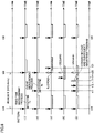
- Fig. 6 is a diagram illustrating patterns of the measurement process executed by condition monitoring device 80.
- the horizontal axis shows time
- the vertical axis shows patterns (1) to (5) of the measurement process in order from above.
- a fixed time trigger signal A is produced at specified times t10, t20, and t30.
- condition monitoring device 80 executes the fixed time measurement process every time a fixed time trigger signal A is received at specified times t10, t20, and t30.
- the fixed time measurement process is a process of outputting to data server 300 the measurement data for a period until a predetermined time Ta has passed from reception of a fixed time trigger signal A, as described above.
- an event trigger signal B is produced at time t11 when the fixed time measurement process is not executed.
- condition monitoring device 80 executes the event measurement process in response to reception of an event trigger signal B at time t11.
- the event measurement process is a process of outputting to data sever 300 the measurement data for a period until a predetermined time Tb has passed from a predetermined time before the time when an event trigger signal B is received.
- each process is executed as usual.
- an event trigger signal B is produced at time t21 when the fixed time measurement process corresponding to the fixed time trigger signal A received at the specified time t20 is being executed.
- condition monitoring device 80 suspends the fixed time measurement process being executed and executes the event measurement process corresponding to the event trigger signal B received at time t21. This suppresses delay in the starting timing of the event measurement process having a higher priority. Accordingly, failure to capture measurement data by the event measurement process having a higher priority can be prevented.
- the event measurement process is executed after the fixed time measurement process being executed is suspended, there is no need for installing an additional processor for handling the parallel process. As a result, delay of the start timing of a measurement process having a higher priority can be suppressed without installing an additional processor.
- the specified time t20 is reached during execution of the event measurement process corresponding to the event trigger signal B received at the specified time t14, and a fixed time trigger signal A is produced.
- the fixed time trigger signal A produced at the specified time t20 is discarded, and the event measurement process being executed continues.
- the event measurement process having a higher priority can be continued without installing an additional processor.
- a first event trigger signal B is produced at time t12, and a second event trigger signal B is produced at the subsequent time t13.
- the first event trigger signal B is registered as a registered trigger signal and executed successively after completion of the event measurement process being executed.
- the second event trigger signal B is temporarily registered as a registered trigger signal but discarded at the point of time when the event measurement process corresponding to the first event trigger signal B is executed. This suppresses unnecessary continuation of the event measurement process.
- the specified time t20 is reached during execution of the event measurement process corresponding to the first event trigger signal B produced at time t11, and a fixed time trigger signal A is produced.
- the fixed time trigger signal A produced at the specified time t20 is discarded, and the event measurement process being executed continues, in the same manner as in the pattern (4).
- condition monitoring device 80 includes trigger setting unit 82 and measurement processing unit 83.
- Trigger setting unit 82 sets the priority of the received trigger signal based on the type of the received trigger signal.
- measurement processing unit 83 suspends the fixed time measurement process being executed and starts the event measurement process corresponding to the received event trigger signal B. This suppresses delay in the start timing of the event measurement process having a higher priority due to the fixed time measurement process having a lower priority being executed. Furthermore, since the fixed time measurement process being executed with a lower priority is suspended, there is no need for installing an additional processor for handling the parallel process.
- measurement processing unit 83 when a fixed time trigger signal A is received and the event measurement process having a priority higher than that of the received fixed time trigger signal A is being executed, measurement processing unit 83 according to the present embodiment discards the received fixed time trigger signal A and continues the event measurement process being executed. Thus, the event measurement process having a higher priority can be continued without installing an additional processor.
- measurement processing unit 83 registers the received event trigger signal B and executes the event measurement process corresponding to the registered event trigger signal B successively after completion of the event measurement process being executed.
- measurement data can be acquired without discarding the event trigger signal B having a higher priority.
- measurement processing unit 83 discards the received fixed time trigger signal A and continues the fixed time measurement process being executed. Thus, unnecessary continuation of the fixed time measurement process having a lower priority can be suppressed.
- condition monitoring system 10 wind turbine generation apparatus, 20 main shaft, 30 blade, 40 gearbox, 50 generator, 60 bearing, 70 vibration sensor, 80 condition monitoring device, 81 trigger detecting unit, 82 trigger setting unit, 83 measurement processing unit, 85 fixed time measurement setting unit, 86 event measurement setting unit, 87 data storage unit, 88 uploading unit, 90 nacelle, 100 tower, 200 external device, 300 data server.
Landscapes
- Engineering & Computer Science (AREA)
- General Engineering & Computer Science (AREA)
- Combustion & Propulsion (AREA)
- Physics & Mathematics (AREA)
- Mechanical Engineering (AREA)
- Life Sciences & Earth Sciences (AREA)
- Sustainable Energy (AREA)
- Chemical & Material Sciences (AREA)
- Sustainable Development (AREA)
- General Physics & Mathematics (AREA)
- Acoustics & Sound (AREA)
- Toxicology (AREA)
- Health & Medical Sciences (AREA)
- Arrangements For Transmission Of Measured Signals (AREA)
- Wind Motors (AREA)
- Testing Of Devices, Machine Parts, Or Other Structures Thereof (AREA)
- Rolling Contact Bearings (AREA)
Abstract
Description
- The present invention relates to a condition monitoring device that executes a measurement process for monitoring a condition of a mechanical component in response to reception of a trigger signal, and more particularly to a condition monitoring device for a wind turbine generation apparatus.
- In a wind turbine generation apparatus, the main shaft connected to blades receiving wind is rotated, and after the gearbox increases the speed of rotation of the main shaft, the rotor of the generator is rotated to generate electric power. Each of the rotation axes of the main shaft, the gear box, and the generator is rotatably supported by a rolling bearing. A condition monitoring system is known that diagnoses a condition of such a bearing using measurement data by a vibration sensor fixed to the bearing.
- Some of such condition monitoring systems for wind turbine generation apparatuses include a condition monitoring device that executes a measurement process of performing measurement with a vibration sensor in response to reception of a trigger signal (for example, see
Japanese Patent Laying-Open No. 2019-52964 - PTL 1:
Japanese Patent Laying-Open No. 2019-52964 - In a condition monitoring system for a wind turbine generation apparatus that executes a vibration measurement process in response to reception of a trigger signal, a trigger source producing a trigger signal is provided outside or inside a condition monitoring device. The trigger source outputs a fixed time trigger signal to the condition monitoring device on a specified time. The condition monitoring device executes a measurement process corresponding to the fixed time trigger signal (hereinafter also referred to as "fixed time measurement process") for a certain time in response to reception of the fixed time trigger signal from the trigger source.
- In a wind turbine generation apparatus, abrupt events such as lightning strikes, earthquakes, and wind gusts may cause damage to bearings and gears. Data obtained when such abrupt events occur may serve as valuable data for diagnosing a condition of the wind turbine generation apparatus. Unfortunately, in the fixed time measurement process, a measurement process is not started until the specified time is reached. With the fixed time measurement, therefore, it is difficult to measure data when abrupt events occur. Thus, it is desirable to allow the trigger source to generate a trigger signal (hereinafter also referred to as "event trigger signal") different from the fixed time trigger signal when an abrupt event occurs and to execute a measurement process (hereinafter also referred to as "event measurement process") corresponding to the event trigger signal.
- Since the fixed time measurement process is repeatedly executed every specified time, a process involving a smaller data volume is executed in the fixed time measurement process. Furthermore, the operation is performed with a smaller measurement data volume, for example, such that measurement is not carried out in an idle state. On the other hand, the event measurement process is executed abruptly and yields measurement data to be used for diagnosis of the wind turbine generation apparatus. Therefore, a process involving a larger data volume is executed in order to obtain more detailed data. Thus, the content of the event measurement process differs from the content of the fixed time measurement process, and it can be said that the event measurement process has a higher priority than the fixed time measurement process.
- Suppose that when the condition monitoring device receives an event trigger signal while executing the fixed time measurement process, the event measurement process is started after the fixed time measurement process being executed is completed. In this case, the start timing of the event measurement process with a high priority may be delayed. To cope with this, it may be possible to simultaneously perform the fixed time measurement process and the event measurement process in parallel, but an additional processor (such as a central processing unit (CPU) and a memory) for handling the parallel process is required, and it is sometimes difficult to reserve a space for installing an additional processor in a compact wind turbine generation apparatus.
- The present disclosure is made to solve the problem above and aimed to suppress delay in the start timing of a measurement process with a high priority without installing an additional processor.
-
- (1) A condition monitoring device executes a measurement process in response to reception of a trigger signal. The condition monitoring device includes a setting unit that sets a priority of a received trigger signal based on a type of the received trigger signal, and a measurement processing unit that executes the measurement process. When the trigger signal is received and when a measurement process resulting from a trigger signal having a priority lower than a priority of the received trigger signal is being executed, the measurement processing unit suspends the measurement process being executed and starts a measurement process corresponding to the received trigger signal.
- (2) In an aspect, when the trigger signal is received and when a measurement process resulting from a trigger signal having a priority higher than a priority of the received trigger signal is being executed, the measurement processing unit discards the received trigger signal and continues the measurement process being executed.
- (3) In an aspect, when the trigger signal is received and when a measurement process resulting from a trigger signal having a same priority as a priority of the received trigger signal is being executed, the measurement processing unit registers the received trigger signal and executes a measurement process corresponding to the registered trigger signal successively after completion of the measurement process being executed.
- (4) In an aspect, when a trigger signal having a first priority is received and when a measurement process resulting from a trigger signal having the first priority is being executed, the measurement processing unit discards the received trigger signal having the first priority and continues the measurement process being executed. When a trigger signal having a second priority higher than the first priority is received and when a measurement process resulting from a trigger signal having the second priority is being executed, the measurement processing unit registers the received trigger signal having the second priority and executes a measurement process corresponding to the registered trigger signal successively after completion of the measurement process being executed.
- (5) In an aspect, the measurement process includes a process of outputting a measurement value of vibration of a bearing installed in a wind turbine generation apparatus.
- (6) A wind turbine generation apparatus according to the present disclosure is a wind turbine generation apparatus including the condition monitoring device described above.
- In the configuration above, when a trigger signal is received and a measurement process having a priority lower than that of the received trigger signal is being executed, the measurement processing unit suspends the measurement process being executed and starts a measurement process corresponding to the received trigger signal. This configuration suppresses delay in the start timing of a measurement process having a higher priority due to a measurement process having a lower priority being executed. Furthermore, since the measurement process being executed with a lower priority is suspended, there is no need for installing an additional processor for handling the parallel process. As a result, delay in the start timing of a measurement process having a higher priority can be suppressed without installing an additional processor. As a result, data is measured at a timing as required, and the presence or absence of abnormality of an apparatus that is a measurement target can be determined accurately based on the measured data.
-
-
Fig. 1 is a diagram schematically showing a wind turbine generation apparatus to which a condition monitoring device is applied. -
Fig. 2 is a functional block diagram showing a functional configuration of a condition monitoring system. -
Fig. 3 is a functional block diagram showing a functional configuration of the condition monitoring device in detail. -
Fig. 4 is a diagram of an exemplary setting table used for setting the priority of a trigger signal and a measurement type. -
Fig. 5 is a flowchart showing an exemplary process of the condition monitoring device. -
Fig. 6 is a diagram illustrating patterns of the measurement process executed by the condition monitoring device. - Embodiments of the present disclosure will be described below with reference to the drawings. In the following drawings, the same or corresponding parts are denoted by the same reference numerals and a description thereof is not repeated.
-
Fig. 1 is a diagram schematically showing a configuration of a windturbine generation apparatus 10 to which acondition monitoring device 80 according to the present embodiment is applied. Windturbine generation apparatus 10 includes amain shaft 20, ablade 30, agearbox 40, agenerator 50, a main shaft bearing (hereinafter simply referred to as "bearing") 60, avibration sensor 70, and acondition monitoring device 80. Gearbox 40,generator 50, bearing 60,vibration sensor 70, andcondition monitoring device 80 are stored in anacelle 90. Nacelle 90 is supported by atower 100. -
Main shaft 20 extends intonacelle 90 to be connected to the input shaft ofgearbox 40 and is rotatably supported by bearing 60.Main shaft 20 then transmits rotational torque generated byblade 30 receiving wind power to the input shaft ofgearbox 40.Blade 30 is provided at the tip end ofmain shaft 20 and converts wind power into rotational torque to be transmitted tomain shaft 20. -
Bearing 60 is fixed innacelle 90 and rotatably supportsmain shaft 20. Bearing 60 is configured with a rolling bearing, for example, configured with a spherical roller bearing, a tapered roller bearing, a cylindrical roller bearing, or a ball bearing. These bearings may be a single row or a double row. - Gearbox 40 is provided between
main shaft 20 andgenerator 50 to increase the rotational speed ofmain shaft 20 for output togenerator 50. As an example, gearbox 40 is configured with a gear speed-increasing mechanism including a planetary gear train, an intermediate shaft, and a high speed shaft. Although not shown, a plurality of bearings rotatably supporting a plurality of shafts are also provided ingearbox 40. -
Generator 50 is connected to the output shaft ofgearbox 40 to generate electric power with the rotational torque received fromgearbox 40.Generator 50 is configured with, for example, an induction generator. A bearing rotatably supporting the rotor is also provided ingenerator 50. -
Vibration sensor 70 is fixed to bearing 60.Vibration sensor 70 measures the vibration waveform of bearing 60 and outputs the measured vibration waveform data to conditionmonitoring device 80.Vibration sensor 70 is configured with, for example, an acceleration sensor having a piezoelectric element. -
Condition monitoring device 80 is provided insidenacelle 90.Condition monitoring device 80 is connected tovibration sensor 70 and stores the detection result byvibration sensor 70 for a certain time.Condition monitoring device 80 then executes a measurement process using the detection result byvibration sensor 70 in response to reception of a trigger signal from an external device and transmits data obtained by the measurement process (hereinafter also referred to as "measurement data") to an external data server. -
Fig. 2 is a functional block diagram showing a functional configuration of acondition monitoring system 1 includingvibration sensor 70 andcondition monitoring device 80 shown inFig. 1 .Condition monitoring system 1 includes anexternal device 200 serving as a trigger source and adata server 300, in addition tovibration sensor 70 andcondition monitoring device 80 described above. -
Vibration sensor 70 andcondition monitoring device 80 are provided insidenacelle 90 as described above. On the other hand,external device 200 anddata server 300 are provided outsidenacelle 90. - When a detection signal is externally input,
external device 200 outputs a trigger signal corresponding to the detection signal to conditionmonitoring device 80 via wired communication or wireless communication. The detection signal input toexternal device 200 includes a "fixed time detection signal Da" and an "event detection signal Db". The "fixed time detection signal Da" is a signal indicating that a predetermined specified time has come. The "event detection signal Db" is a signal indicating that an abrupt event that may cause damage to windturbine generation apparatus 10 is detected. The event detection signal Db includes a signal indicating that abnormal vibration is detected, a signal indicating a lightning strike is detected, a signal indicating a temperature variation exceeding a reference value is detected, a signal indicating that a wind speed change exceeding a reference value is detected, a signal indicating that a wind direction change exceeding a reference value is detected, and a signal indicating that emergency stop is detected. - When a fixed time detection signal Da is externally input,
external device 200 outputs a "fixed time trigger signal A" corresponding to the fixed time detection signal Da tocondition monitoring device 80. When an event detection signal Db is externally received,external device 200 outputs an "event trigger signal B" corresponding to the event detection signal Db to conditionmonitoring device 80. Examples ofexternal device 200 include a programmable logic controller (PLC), supervisory control and data acquisition (SCADA), and a computer for measurement. - Although one
external device 200 is illustrated inFig. 2 ,external device 200 may be divided into two or more. Furthermore, althoughexternal device 200 is provided outsidenacelle 90 inFig. 2 ,external device 200 may be provided insidenacelle 90. For example, an external device having the function of outputting a fixed time trigger signal A may be provided insidenacelle 90, and an external device having the function of outputting an event trigger signal B may be provided outsidenacelle 90. - In response to reception of a trigger signal (fixed time trigger signal A or event trigger signal B) from
external device 200,condition monitoring device 80 executes a measurement process using the detection result byvibration sensor 70 and transmits (uploads) measurement data obtained by the measurement process todata server 300. -
Fig. 3 is a functional block diagram showing a functional configuration ofcondition monitoring device 80 in detail.Condition monitoring device 80 includes atrigger detecting unit 81, atrigger setting unit 82, ameasurement processing unit 83, a fixed timemeasurement setting unit 85, an eventmeasurement setting unit 86, adata storage unit 87, and anuploading unit 88. - Upon receiving a trigger signal from
external device 200,trigger detecting unit 81 stores the time when the trigger signal is received and requests trigger settingunit 82 to set the priority and the measurement type corresponding to the received trigger signal. Trigger settingunit 82 sets the priority and the measurement type corresponding to the trigger signal received fromtrigger detecting unit 81 and transmits the result as a trigger setting result to trigger detectingunit 81. -
Fig. 4 is a diagram of an exemplary setting table used to set the priority and the measurement type of a trigger signal. As shown inFig. 4 , in this setting table, "fixed time measurement" is set as the measurement type and "0" is set as the priority for the fixed time trigger signal A. "Event measurement" is set as the measurement type and "1" is set as the priority for the event trigger signal B. The priority "1" is meant to be higher than the priority "0". Trigger settingunit 82 refers to the setting table as shown inFig. 4 to set the priority and the measurement type corresponding to a trigger signal received fromtrigger detecting unit 81 and transmits the result as a trigger setting result to trigger detectingunit 81. - Returning to
Fig. 3 , upon receiving the trigger setting result fromtrigger setting unit 82,trigger detecting unit 81 notifiesmeasurement processing unit 83 of the trigger setting result received fromtrigger setting unit 82, together with the time when the trigger signal is received. -
Measurement processing unit 83 is configured to execute a measurement process in accordance with the notification fromtrigger detecting unit 81. When the measurement type included in the trigger setting result given fromtrigger detecting unit 81 is "fixed time measurement",measurement processing unit 83 requests fixed timemeasurement setting unit 85 to set the process content of the fixed time measurement. In response to the request frommeasurement processing unit 83, fixed timemeasurement setting unit 85 sets the content of the fixed time measurement process and returns the set process content tomeasurement processing unit 83. In the present embodiment, the fixed time measurement process is set to the content "measurement data for a period until a predetermined time Ta has passed from reception of a fixed time trigger signal A is output todata server 300". - On the other hand, when the measurement type included in the trigger setting result given from
trigger detecting unit 81 is "event measurement",measurement processing unit 83 requests eventmeasurement setting unit 86 to set the content of the event measurement process. In response to the request frommeasurement processing unit 83, eventmeasurement setting unit 86 sets the content of the event measurement process and returns the set process content tomeasurement processing unit 83. In the present embodiment, the event measurement process is set to the content "measurement data for a period until a predetermined time Tb has passed from a predetermined time before the time when the event trigger signal B is received is output todata server 300". In this way, the content of the event measurement process differs from the content of the fixed time measurement process. - The contents of the fixed time measurement process and the event measurement process are illustrated only by way of example and are not limited to the contents described above. For example, the fixed time measurement process may be a process involving a smaller data volume since it is a process that is always repeatedly carried out, whereas the event measurement process may be a process involving a larger data volume in order to obtain more detailed data.
-
Measurement processing unit 83 reads measurement data stored indata storage unit 87 in accordance with the process content received from fixed timemeasurement setting unit 85 or eventmeasurement setting unit 86 and outputs the read measurement data to uploadingunit 88. - When the fixed time measurement process is to be executed,
measurement processing unit 83 requestsdata storage unit 87 to transmit measurement data for a period until a predetermined time Ta has passed from reception of a fixed time trigger signal A. When the event measurement process is to be executed,measurement processing unit 83 requestsdata storage unit 87 to transmit measurement data for a period until a predetermined time Tb has passed from a predetermined time before an event trigger signal B is received. -
Data storage unit 87 always acquires measurement data byvibration sensor 70 and stores the acquired measurement data for a certain period (a period sufficiently longer than the predetermined times Ta and Tb), together with the measurement time.Data storage unit 87 reads measurement data for a period requested bymeasurement processing unit 83 from among the stored measurement data and transmits the read measurement data tomeasurement processing unit 83.Measurement processing unit 83 outputs the measurement data received fromdata storage unit 87 to uploadingunit 88. - Uploading
unit 88 outputs (uploads) the measurement data received frommeasurement processing unit 83 todata server 300 via wired communication or wireless communication, together with the time when a trigger signal is received and the trigger setting result bytrigger setting unit 82. -
Data server 300 performs a process of diagnosing a condition of windturbine generation apparatus 10, based on the measurement data received from uploadingunit 88. - The fixed time measurement process is repeatedly executed every specified time. By comparison, the event measurement process is executed when abrupt events such as lightning strikes, earthquakes, and wind gusts occur, and the measurement data obtained by the event measurement process is used for diagnosis of wind
turbine generation apparatus 10. Therefore, it can be said that the event measurement process has a higher priority than the fixed time measurement process. - Suppose that when an event trigger signal B is received while the fixed time measurement process is being executed, the event measurement process is started after the fixed time measurement process being executed is completed. In this case, however, the start timing of the event measurement process with a higher priority may be delayed. To cope with this, it may be possible to simultaneously perform the fixed time measurement process and the event measurement process in parallel, but an additional processor (such as a CPU and a memory) for handling the parallel process is required, and it is sometimes difficult to reserve a space for installing an additional processor in
nacelle 90 of compact windturbine generation apparatus 10. - In view of the above,
condition monitoring device 80 according to the present embodiment sets a priority for a trigger signal received fromexternal device 200. Specifically, as described above, the priority of a fixed time trigger signal A is set to "0", and the priority of an event trigger signal B is set to "1" higher than zero. Then, when an event trigger signal B is received and the fixed time measurement process caused by a fixed time trigger signal A having a priority "0" lower than the priority "1" of the event trigger signal B is being executed,condition monitoring device 80 halts the fixed time measurement process being executed and starts the event measurement process corresponding to the received event trigger signal B. This can suppress delay in the starting timing of an event measurement process having a higher priority. -
Fig. 5 is a flowchart showing an exemplary process in whichcondition monitoring device 80 executes a measurement process. This flowchart is repeatedly performed every time a predetermined condition is met (for example, at predetermined intervals). First of all,condition monitoring device 80 determines whether a trigger signal is received from external device 200 (step S10). - If
condition monitoring device 80 receives a trigger signal from external device 200 (YES at step S10),condition monitoring device 80 refers to the setting table above shown inFig. 4 and determines whether the priority of the trigger signal received this time is "1" (that is, whether the trigger signal is an event trigger signal B) (step S20). - If the priority of the received trigger signal is "1" (YES at step S20), that is, if an event trigger signal B is received,
condition monitoring device 80 determines whether the event measurement process having the same priority "1" as the priority "1" of the event trigger signal B received this time is being executed (step S22). - If the event measurement process is being executed (YES at step S22),
condition monitoring device 80 registers the event trigger signal B received this time (step S24). Thus, the event measurement process being executed continues as it is. Subsequently,condition monitoring device 80 skips the subsequent process and moves the process to return. - The event trigger signal B registered at step S24 is treated as "registered trigger signal" in the next and subsequent computation cycles. The event measurement process corresponding to the registered trigger signal is executed successively after completion of the event measurement process being executed.
- If the event measurement process is not being executed (NO at step S22),
condition monitoring device 80 determines whether the fixed time measurement process having a priority "0" lower than the priority of the event trigger signal B received this time is being executed (step S26). - If the fixed time measurement process is not being executed (NO at step S26),
condition monitoring device 80 executes the event measurement process corresponding to the event trigger signal B received this time (step S30). - On the other hand, if the fixed time measurement process is being executed (YES at step S26),
condition monitoring device 80 suspends the fixed time measurement process being executed (step S28) and executes the event measurement process corresponding to the event trigger signal B received this time (step S30). - If the priority of the received trigger signal is "0" (NO at step S20), that is, if a fixed time trigger signal A is received,
condition monitoring device 80 determines whether the event measurement process having a priority "1" higher than the priority of the received fixed time trigger signal A is being executed (step S40). - If the event measurement process is being executed (YES at step S40),
condition monitoring device 80 discards the received fixed time trigger signal A (step S46). Thus, the event measurement process having a priority "1" being executed continues. - If the event measurement process is not being executed (NO at step S40),
condition monitoring device 80 determines whether the fixed time measurement process having the same priority "0" as the priority of the received fixed time trigger signal A is being executed (step S42). If the fixed time measurement process is being executed (YES at step S42),condition monitoring device 80 discards the received fixed time trigger signal A (step S46). Thus, the fixed time measurement process having a priority "0" being executed continues. - If the fixed time measurement process is not being executed (NO at step S42),
condition monitoring device 80 executes the fixed time measurement process corresponding to the fixed time trigger signal A received this time (step S44). - The process performed when it is determined that a trigger signal is not received at step S10 (NO at step S10) will now be described. In this case,
condition monitoring device 80 determines whether the event measurement process having a priority "1" is being executed (step S11). If the event measurement process is being executed (YES at step S11),condition monitoring device 80 skips the subsequent process and moves the process to return. - If the event measurement process is not being executed (NO at step S11),
condition monitoring device 80 determines whether a registered trigger signal exists (step S12). The registered trigger signal is the event trigger signal B registered at step S24 in the last and preceding computation cycles. If no registered trigger signal exists (NO at step S12),condition monitoring device 80 skips the subsequent process and moves the process to return. - If a registered trigger signal exists (YES at step S12),
condition monitoring device 80 executes the process subsequent to step S20 for the registered trigger signal. That is, since the registered trigger signal is an event trigger signal B having a priority "1", the determination by monitoringdevice 80 at step S20 is YES. Furthermore, since the event measurement process having a priority "1" is not being executed as determined at step S11, the determination at step S22 is NO, and the event measurement process corresponding to the registered trigger signal is executed at step S30. - After step S30,
condition monitoring device 80 discards the registered trigger signal (step S32). That is, even when a plurality of registered trigger signals exist,condition monitoring device 80 according to the present embodiment discards the second and subsequent registered trigger signals, because the event measurement process corresponding to the first registered trigger signal has been executed. Thus, the event measurement process corresponding to the second and subsequent registered trigger signals is not executed. -
Fig. 6 is a diagram illustrating patterns of the measurement process executed bycondition monitoring device 80. InFig. 6 , the horizontal axis shows time, and the vertical axis shows patterns (1) to (5) of the measurement process in order from above. InFig. 6 , in each of the patterns (1) to (5), a fixed time trigger signal A is produced at specified times t10, t20, and t30. - In the pattern (1), an event trigger signal B is not produced at any time. In this case,
condition monitoring device 80 executes the fixed time measurement process every time a fixed time trigger signal A is received at specified times t10, t20, and t30. In the present embodiment, the fixed time measurement process is a process of outputting todata server 300 the measurement data for a period until a predetermined time Ta has passed from reception of a fixed time trigger signal A, as described above. - In the pattern (2), an event trigger signal B is produced at time t11 when the fixed time measurement process is not executed. In this case,
condition monitoring device 80 executes the event measurement process in response to reception of an event trigger signal B at time t11. In the present embodiment, the event measurement process is a process of outputting to data sever 300 the measurement data for a period until a predetermined time Tb has passed from a predetermined time before the time when an event trigger signal B is received. In the pattern (2), since the period in which the fixed time measurement process is executed does not overlap a period in which the event measurement process is executed, each process is executed as usual. - In the pattern (3), an event trigger signal B is produced at time t21 when the fixed time measurement process corresponding to the fixed time trigger signal A received at the specified time t20 is being executed. In this case, in response to reception of an event trigger signal B at time t21,
condition monitoring device 80 suspends the fixed time measurement process being executed and executes the event measurement process corresponding to the event trigger signal B received at time t21. This suppresses delay in the starting timing of the event measurement process having a higher priority. Accordingly, failure to capture measurement data by the event measurement process having a higher priority can be prevented. Furthermore, since the event measurement process is executed after the fixed time measurement process being executed is suspended, there is no need for installing an additional processor for handling the parallel process. As a result, delay of the start timing of a measurement process having a higher priority can be suppressed without installing an additional processor. - In the pattern (4), the specified time t20 is reached during execution of the event measurement process corresponding to the event trigger signal B received at the specified time t14, and a fixed time trigger signal A is produced. In this case, the fixed time trigger signal A produced at the specified time t20 is discarded, and the event measurement process being executed continues. Thus, the event measurement process having a higher priority can be continued without installing an additional processor.
- In the pattern (5), during execution of the event measurement process corresponding to the event trigger signal B produced at time t11, a first event trigger signal B is produced at time t12, and a second event trigger signal B is produced at the subsequent time t13. In this case, the first event trigger signal B is registered as a registered trigger signal and executed successively after completion of the event measurement process being executed. Thus, measurement data can be acquired without discarding an event trigger signal B having a higher priority.
- The second event trigger signal B is temporarily registered as a registered trigger signal but discarded at the point of time when the event measurement process corresponding to the first event trigger signal B is executed. This suppresses unnecessary continuation of the event measurement process.
- In the pattern (5), the specified time t20 is reached during execution of the event measurement process corresponding to the first event trigger signal B produced at time t11, and a fixed time trigger signal A is produced. In this case, the fixed time trigger signal A produced at the specified time t20 is discarded, and the event measurement process being executed continues, in the same manner as in the pattern (4).
- As described above,
condition monitoring device 80 according to the present embodiment includestrigger setting unit 82 andmeasurement processing unit 83. Trigger settingunit 82 sets the priority of the received trigger signal based on the type of the received trigger signal. When an event trigger signal B is received and the fixed time measurement process having a priority lower than that of the received event trigger signal B is being executed,measurement processing unit 83 suspends the fixed time measurement process being executed and starts the event measurement process corresponding to the received event trigger signal B. This suppresses delay in the start timing of the event measurement process having a higher priority due to the fixed time measurement process having a lower priority being executed. Furthermore, since the fixed time measurement process being executed with a lower priority is suspended, there is no need for installing an additional processor for handling the parallel process. As a result, delay in the start timing of the event measurement process having a higher priority can be suppressed without installing an additional processor. As a result, data is measured at a timing as required, and the presence or absence of abnormality of windturbine generation apparatus 10 that is a measurement target can be determined accurately based on the measured data. - Furthermore, when a fixed time trigger signal A is received and the event measurement process having a priority higher than that of the received fixed time trigger signal A is being executed,
measurement processing unit 83 according to the present embodiment discards the received fixed time trigger signal A and continues the event measurement process being executed. Thus, the event measurement process having a higher priority can be continued without installing an additional processor. - Furthermore, when an event trigger signal B is received and the event measurement process having the same priority as that of the received event trigger signal B is being executed,
measurement processing unit 83 according to the present embodiment registers the received event trigger signal B and executes the event measurement process corresponding to the registered event trigger signal B successively after completion of the event measurement process being executed. Thus, measurement data can be acquired without discarding the event trigger signal B having a higher priority. - Furthermore, when a fixed time trigger signal A having a priority "0" is received and the fixed time measurement process having the same priority "0" as that of the received fixed time trigger signal A is being executed,
measurement processing unit 83 according to the present embodiment discards the received fixed time trigger signal A and continues the fixed time measurement process being executed. Thus, unnecessary continuation of the fixed time measurement process having a lower priority can be suppressed. - The embodiment disclosed here should be understood as being illustrative rather than being limitative in all respects. The scope of the present disclosure is shown not in the foregoing description but in the claims, and it is intended that all modifications that come within the meaning and range of equivalence to the claims are embraced here.
- 1 condition monitoring system, 10 wind turbine generation apparatus, 20 main shaft, 30 blade, 40 gearbox, 50 generator, 60 bearing, 70 vibration sensor, 80 condition monitoring device, 81 trigger detecting unit, 82 trigger setting unit, 83 measurement processing unit, 85 fixed time measurement setting unit, 86 event measurement setting unit, 87 data storage unit, 88 uploading unit, 90 nacelle, 100 tower, 200 external device, 300 data server.
Claims (6)
- A condition monitoring device that executes a measurement process in response to reception of a trigger signal, the condition monitoring device comprising:a setting unit that sets a priority of a received trigger signal based on a type of the received trigger signal; anda measurement processing unit that executes the measurement process,wherein when the trigger signal is received and when a measurement process resulting from a trigger signal having a priority lower than a priority of the received trigger signal is being executed, the measurement processing unit suspends the measurement process being executed and starts a measurement process corresponding to the received trigger signal.
- The condition monitoring device according to claim 1, wherein when the trigger signal is received and when a measurement process resulting from a trigger signal having a priority higher than a priority of the received trigger signal is being executed, the measurement processing unit discards the received trigger signal and continues the measurement process being executed.
- The condition monitoring device according to claim 1 or 2, wherein when the trigger signal is received and when a measurement process resulting from a trigger signal having a same priority as a priority of the received trigger signal is being executed, the measurement processing unit registers the received trigger signal and executes a measurement process corresponding to the registered trigger signal successively after completion of the measurement process being executed.
- The condition monitoring device according to claim 1 or 2, whereinwhen a trigger signal having a first priority is received and when a measurement process resulting from a trigger signal having the first priority is being executed, the measurement processing unit discards the received trigger signal having the first priority and continues the measurement process being executed, andwhen a trigger signal having a second priority higher than the first priority is received and when a measurement process resulting from a trigger signal having the second priority is being executed, the measurement processing unit registers the received trigger signal having the second priority and executes a measurement process corresponding to the registered trigger signal successively after completion of the measurement process being executed.
- The condition monitoring device according to any one of claims 1 to 4, wherein the measurement process includes a process of outputting a measurement value of vibration of a bearing installed in a wind turbine generation apparatus.
- A wind turbine generation apparatus comprising the condition monitoring device according to any one of claims 1 to 4.
Applications Claiming Priority (2)
| Application Number | Priority Date | Filing Date | Title |
|---|---|---|---|
| JP2020000302A JP7433052B2 (en) | 2020-01-06 | 2020-01-06 | Condition monitoring device and wind power generator equipped with condition monitoring device |
| PCT/JP2021/000013 WO2021141003A1 (en) | 2020-01-06 | 2021-01-04 | State monitoring device and wind power generation device provided with state monitoring device |
Publications (3)
| Publication Number | Publication Date |
|---|---|
| EP4089390A1 true EP4089390A1 (en) | 2022-11-16 |
| EP4089390A4 EP4089390A4 (en) | 2024-01-17 |
| EP4089390B1 EP4089390B1 (en) | 2025-07-02 |
Family
ID=76788016
Family Applications (1)
| Application Number | Title | Priority Date | Filing Date |
|---|---|---|---|
| EP21738941.0A Active EP4089390B1 (en) | 2020-01-06 | 2021-01-04 | Condition monitoring device and wind turbine generation apparatus including condition monitoring device |
Country Status (4)
| Country | Link |
|---|---|
| EP (1) | EP4089390B1 (en) |
| JP (1) | JP7433052B2 (en) |
| CN (1) | CN114930143B (en) |
| WO (1) | WO2021141003A1 (en) |
Families Citing this family (1)
| Publication number | Priority date | Publication date | Assignee | Title |
|---|---|---|---|---|
| CN120352132B (en) * | 2025-06-23 | 2025-09-05 | 湘潭华进重装科技股份有限公司 | Multi-mode mechanical property testing device of expanding machine |
Family Cites Families (14)
| Publication number | Priority date | Publication date | Assignee | Title |
|---|---|---|---|---|
| JP2575973B2 (en) * | 1991-06-20 | 1997-01-29 | 株式会社ミツトヨ | Task scheduling method for measurement data processing system |
| US5636124A (en) * | 1995-03-08 | 1997-06-03 | Allen-Bradley Company, Inc. | Multitasking industrial controller |
| US7385496B2 (en) * | 2002-04-15 | 2008-06-10 | Matsushita Electric Industrial Co., Ltd. | Monitoring system |
| JP2010169439A (en) * | 2009-01-20 | 2010-08-05 | Vector Co Ltd | Electronic micrometer |
| CN201546898U (en) * | 2009-12-09 | 2010-08-11 | 三一电气有限责任公司 | Wind turbine and its condition monitoring system |
| JP2013011232A (en) * | 2011-06-29 | 2013-01-17 | Mitsubishi Heavy Ind Ltd | Windmill repair timing determination support device and repair timing determination support method |
| JP6123442B2 (en) * | 2013-04-09 | 2017-05-10 | オムロン株式会社 | Sensor device, measurement system, and measurement method |
| GB2517152A (en) * | 2013-08-12 | 2015-02-18 | Gde Technology Ltd | Position sensor |
| US20160087911A1 (en) * | 2014-09-19 | 2016-03-24 | International Business Machines Corporation | Nas client access prioritization |
| JP6820771B2 (en) * | 2016-03-17 | 2021-01-27 | Ntn株式会社 | Condition monitoring system and wind power generator |
| CN106246476B (en) * | 2016-09-30 | 2018-04-20 | 广州特种承压设备检测研究院 | Marine wind driven generator blade intelligent fault monitors system and method |
| JP6851684B2 (en) * | 2016-11-30 | 2021-03-31 | 日東工業株式会社 | Combined measurement system |
| JP6885833B2 (en) | 2017-09-15 | 2021-06-16 | Ntn株式会社 | Condition monitoring system and data processing equipment |
| CN108965390A (en) * | 2018-06-14 | 2018-12-07 | 深圳华龙讯达信息技术股份有限公司 | A kind of equipment running status monitoring method and device |
-
2020
- 2020-01-06 JP JP2020000302A patent/JP7433052B2/en active Active
-
2021
- 2021-01-04 WO PCT/JP2021/000013 patent/WO2021141003A1/en not_active Ceased
- 2021-01-04 EP EP21738941.0A patent/EP4089390B1/en active Active
- 2021-01-04 CN CN202180008305.5A patent/CN114930143B/en active Active
Also Published As
| Publication number | Publication date |
|---|---|
| JP2021110543A (en) | 2021-08-02 |
| JP7433052B2 (en) | 2024-02-19 |
| EP4089390A4 (en) | 2024-01-17 |
| EP4089390B1 (en) | 2025-07-02 |
| CN114930143B (en) | 2025-12-05 |
| WO2021141003A1 (en) | 2021-07-15 |
| CN114930143A (en) | 2022-08-19 |
Similar Documents
| Publication | Publication Date | Title |
|---|---|---|
| JP6665062B2 (en) | Condition monitoring device | |
| EP2264315B1 (en) | Operating a wind turbine at motor over-temperature conditions | |
| CN112523946B (en) | Variable pitch control method and device for wind generating set and medium | |
| CN110234972B (en) | Condition monitoring system and wind turbine | |
| EP2951737B1 (en) | Method and system for use in dynamically configuring data acquisition systems | |
| CN109209765B (en) | The pitch control method and system of wind power generating set | |
| CN106574606A (en) | State monitoring system and wind power generation system provided with same | |
| CN108240303B (en) | Wind vane fault redundancy operation method and system for wind driven generator | |
| CN107061183A (en) | A kind of automation method for diagnosing faults of offshore wind farm unit | |
| CN108885158B (en) | Condition monitoring system and wind power plant including the same | |
| EP4089390B1 (en) | Condition monitoring device and wind turbine generation apparatus including condition monitoring device | |
| CN117906991A (en) | Machine Health Monitoring of Rotating Machinery | |
| EP3805557A1 (en) | Wind power generation system | |
| EP4130462B1 (en) | Wind turbine generator, and minimum rotational speed control method and device therefor | |
| CN106286127B (en) | A kind of wind-driven generator group parts oscillation monitoring method | |
| CN110685869B (en) | Fault diagnosis method, device and equipment for wind turbine generator | |
| JP2011132961A (en) | System and method for triggering emergency system of wind turbine, wind turbine, computer program and computer readable record medium | |
| CN201546898U (en) | Wind turbine and its condition monitoring system | |
| CN107795436A (en) | Control method, master controller, system and the central controller of wind power generating set | |
| JP2016031047A (en) | State monitoring system and wind power generation system including the same | |
| CN117489537B (en) | A communication fault judgment and processing method in a wind turbine pitch control system | |
| JP2017219325A (en) | Abnormality diagnostic device and abnormality diagnostic method of rotary part | |
| CN112160868B (en) | Monitoring method, system, equipment and medium of variable pitch system | |
| CN113994088A (en) | Method for computer-implemented monitoring of components of a wind turbine | |
| CN112112757A (en) | Anti-flash-off control method, system, equipment and medium for variable pitch system |
Legal Events
| Date | Code | Title | Description |
|---|---|---|---|
| STAA | Information on the status of an ep patent application or granted ep patent |
Free format text: STATUS: THE INTERNATIONAL PUBLICATION HAS BEEN MADE |
|
| PUAI | Public reference made under article 153(3) epc to a published international application that has entered the european phase |
Free format text: ORIGINAL CODE: 0009012 |
|
| STAA | Information on the status of an ep patent application or granted ep patent |
Free format text: STATUS: REQUEST FOR EXAMINATION WAS MADE |
|
| 17P | Request for examination filed |
Effective date: 20220729 |
|
| AK | Designated contracting states |
Kind code of ref document: A1 Designated state(s): AL AT BE BG CH CY CZ DE DK EE ES FI FR GB GR HR HU IE IS IT LI LT LU LV MC MK MT NL NO PL PT RO RS SE SI SK SM TR |
|
| DAV | Request for validation of the european patent (deleted) | ||
| DAX | Request for extension of the european patent (deleted) | ||
| A4 | Supplementary search report drawn up and despatched |
Effective date: 20231218 |
|
| RIC1 | Information provided on ipc code assigned before grant |
Ipc: G01M 13/045 20190101ALI20231212BHEP Ipc: F16C 41/00 20060101ALI20231212BHEP Ipc: F16C 19/52 20060101ALI20231212BHEP Ipc: F03D 17/00 20160101ALI20231212BHEP Ipc: F03D 1/06 20060101ALI20231212BHEP Ipc: G01M 99/00 20110101AFI20231212BHEP |
|
| STAA | Information on the status of an ep patent application or granted ep patent |
Free format text: STATUS: EXAMINATION IS IN PROGRESS |
|
| 17Q | First examination report despatched |
Effective date: 20240723 |
|
| GRAP | Despatch of communication of intention to grant a patent |
Free format text: ORIGINAL CODE: EPIDOSNIGR1 |
|
| STAA | Information on the status of an ep patent application or granted ep patent |
Free format text: STATUS: GRANT OF PATENT IS INTENDED |
|
| INTG | Intention to grant announced |
Effective date: 20241223 |
|
| GRAS | Grant fee paid |
Free format text: ORIGINAL CODE: EPIDOSNIGR3 |
|
| GRAA | (expected) grant |
Free format text: ORIGINAL CODE: 0009210 |
|
| STAA | Information on the status of an ep patent application or granted ep patent |
Free format text: STATUS: THE PATENT HAS BEEN GRANTED |
|
| AK | Designated contracting states |
Kind code of ref document: B1 Designated state(s): AL AT BE BG CH CY CZ DE DK EE ES FI FR GB GR HR HU IE IS IT LI LT LU LV MC MK MT NL NO PL PT RO RS SE SI SK SM TR |
|
| REG | Reference to a national code |
Ref country code: GB Ref legal event code: FG4D |
|
| REG | Reference to a national code |
Ref country code: CH Ref legal event code: EP |
|
| REG | Reference to a national code |
Ref country code: DE Ref legal event code: R096 Ref document number: 602021033389 Country of ref document: DE |
|
| REG | Reference to a national code |
Ref country code: IE Ref legal event code: FG4D |
|
| REG | Reference to a national code |
Ref country code: NL Ref legal event code: MP Effective date: 20250702 |
|
| PG25 | Lapsed in a contracting state [announced via postgrant information from national office to epo] |
Ref country code: PT Free format text: LAPSE BECAUSE OF FAILURE TO SUBMIT A TRANSLATION OF THE DESCRIPTION OR TO PAY THE FEE WITHIN THE PRESCRIBED TIME-LIMIT Effective date: 20251103 |
|
| PG25 | Lapsed in a contracting state [announced via postgrant information from national office to epo] |
Ref country code: NL Free format text: LAPSE BECAUSE OF FAILURE TO SUBMIT A TRANSLATION OF THE DESCRIPTION OR TO PAY THE FEE WITHIN THE PRESCRIBED TIME-LIMIT Effective date: 20250702 |
|
| REG | Reference to a national code |
Ref country code: AT Ref legal event code: MK05 Ref document number: 1809706 Country of ref document: AT Kind code of ref document: T Effective date: 20250702 |
|
| PG25 | Lapsed in a contracting state [announced via postgrant information from national office to epo] |
Ref country code: IS Free format text: LAPSE BECAUSE OF FAILURE TO SUBMIT A TRANSLATION OF THE DESCRIPTION OR TO PAY THE FEE WITHIN THE PRESCRIBED TIME-LIMIT Effective date: 20251102 |
|
| PG25 | Lapsed in a contracting state [announced via postgrant information from national office to epo] |
Ref country code: NO Free format text: LAPSE BECAUSE OF FAILURE TO SUBMIT A TRANSLATION OF THE DESCRIPTION OR TO PAY THE FEE WITHIN THE PRESCRIBED TIME-LIMIT Effective date: 20251002 |
|
| REG | Reference to a national code |
Ref country code: LT Ref legal event code: MG9D |
|
| PG25 | Lapsed in a contracting state [announced via postgrant information from national office to epo] |
Ref country code: AT Free format text: LAPSE BECAUSE OF FAILURE TO SUBMIT A TRANSLATION OF THE DESCRIPTION OR TO PAY THE FEE WITHIN THE PRESCRIBED TIME-LIMIT Effective date: 20250702 |
|
| PG25 | Lapsed in a contracting state [announced via postgrant information from national office to epo] |
Ref country code: FI Free format text: LAPSE BECAUSE OF FAILURE TO SUBMIT A TRANSLATION OF THE DESCRIPTION OR TO PAY THE FEE WITHIN THE PRESCRIBED TIME-LIMIT Effective date: 20250702 |
|
| PG25 | Lapsed in a contracting state [announced via postgrant information from national office to epo] |
Ref country code: HR Free format text: LAPSE BECAUSE OF FAILURE TO SUBMIT A TRANSLATION OF THE DESCRIPTION OR TO PAY THE FEE WITHIN THE PRESCRIBED TIME-LIMIT Effective date: 20250702 |
|
| PG25 | Lapsed in a contracting state [announced via postgrant information from national office to epo] |
Ref country code: GR Free format text: LAPSE BECAUSE OF FAILURE TO SUBMIT A TRANSLATION OF THE DESCRIPTION OR TO PAY THE FEE WITHIN THE PRESCRIBED TIME-LIMIT Effective date: 20251003 |
|
| PG25 | Lapsed in a contracting state [announced via postgrant information from national office to epo] |
Ref country code: CZ Free format text: LAPSE BECAUSE OF FAILURE TO SUBMIT A TRANSLATION OF THE DESCRIPTION OR TO PAY THE FEE WITHIN THE PRESCRIBED TIME-LIMIT Effective date: 20250702 Ref country code: SE Free format text: LAPSE BECAUSE OF FAILURE TO SUBMIT A TRANSLATION OF THE DESCRIPTION OR TO PAY THE FEE WITHIN THE PRESCRIBED TIME-LIMIT Effective date: 20250702 |
|
| PG25 | Lapsed in a contracting state [announced via postgrant information from national office to epo] |
Ref country code: LV Free format text: LAPSE BECAUSE OF FAILURE TO SUBMIT A TRANSLATION OF THE DESCRIPTION OR TO PAY THE FEE WITHIN THE PRESCRIBED TIME-LIMIT Effective date: 20250702 |
|
| PG25 | Lapsed in a contracting state [announced via postgrant information from national office to epo] |
Ref country code: PL Free format text: LAPSE BECAUSE OF FAILURE TO SUBMIT A TRANSLATION OF THE DESCRIPTION OR TO PAY THE FEE WITHIN THE PRESCRIBED TIME-LIMIT Effective date: 20250702 Ref country code: BG Free format text: LAPSE BECAUSE OF FAILURE TO SUBMIT A TRANSLATION OF THE DESCRIPTION OR TO PAY THE FEE WITHIN THE PRESCRIBED TIME-LIMIT Effective date: 20250702 |
|
| PG25 | Lapsed in a contracting state [announced via postgrant information from national office to epo] |
Ref country code: RS Free format text: LAPSE BECAUSE OF FAILURE TO SUBMIT A TRANSLATION OF THE DESCRIPTION OR TO PAY THE FEE WITHIN THE PRESCRIBED TIME-LIMIT Effective date: 20251002 |
|
| PG25 | Lapsed in a contracting state [announced via postgrant information from national office to epo] |
Ref country code: ES Free format text: LAPSE BECAUSE OF FAILURE TO SUBMIT A TRANSLATION OF THE DESCRIPTION OR TO PAY THE FEE WITHIN THE PRESCRIBED TIME-LIMIT Effective date: 20250702 |
|
| PG25 | Lapsed in a contracting state [announced via postgrant information from national office to epo] |
Ref country code: SM Free format text: LAPSE BECAUSE OF FAILURE TO SUBMIT A TRANSLATION OF THE DESCRIPTION OR TO PAY THE FEE WITHIN THE PRESCRIBED TIME-LIMIT Effective date: 20250702 |
|
| PG25 | Lapsed in a contracting state [announced via postgrant information from national office to epo] |
Ref country code: DK Free format text: LAPSE BECAUSE OF FAILURE TO SUBMIT A TRANSLATION OF THE DESCRIPTION OR TO PAY THE FEE WITHIN THE PRESCRIBED TIME-LIMIT Effective date: 20250702 |
|
| PGFP | Annual fee paid to national office [announced via postgrant information from national office to epo] |
Ref country code: DE Payment date: 20260326 Year of fee payment: 6 |
|
| PG25 | Lapsed in a contracting state [announced via postgrant information from national office to epo] |
Ref country code: IT Free format text: LAPSE BECAUSE OF FAILURE TO SUBMIT A TRANSLATION OF THE DESCRIPTION OR TO PAY THE FEE WITHIN THE PRESCRIBED TIME-LIMIT Effective date: 20250702 |
|
| PG25 | Lapsed in a contracting state [announced via postgrant information from national office to epo] |
Ref country code: SK Free format text: LAPSE BECAUSE OF FAILURE TO SUBMIT A TRANSLATION OF THE DESCRIPTION OR TO PAY THE FEE WITHIN THE PRESCRIBED TIME-LIMIT Effective date: 20250702 Ref country code: EE Free format text: LAPSE BECAUSE OF FAILURE TO SUBMIT A TRANSLATION OF THE DESCRIPTION OR TO PAY THE FEE WITHIN THE PRESCRIBED TIME-LIMIT Effective date: 20250702 |
|
| PLBE | No opposition filed within time limit |
Free format text: ORIGINAL CODE: 0009261 |
|
| STAA | Information on the status of an ep patent application or granted ep patent |
Free format text: STATUS: NO OPPOSITION FILED WITHIN TIME LIMIT |