EP4089375B1 - Monopipe adapter for a gas meter - Google Patents
Monopipe adapter for a gas meter Download PDFInfo
- Publication number
- EP4089375B1 EP4089375B1 EP21173877.8A EP21173877A EP4089375B1 EP 4089375 B1 EP4089375 B1 EP 4089375B1 EP 21173877 A EP21173877 A EP 21173877A EP 4089375 B1 EP4089375 B1 EP 4089375B1
- Authority
- EP
- European Patent Office
- Prior art keywords
- monopipe
- gas
- adapter
- enclosure
- connector
- Prior art date
- Legal status (The legal status is an assumption and is not a legal conclusion. Google has not performed a legal analysis and makes no representation as to the accuracy of the status listed.)
- Active
Links
Images



Classifications
-
- G—PHYSICS
- G01—MEASURING; TESTING
- G01F—MEASURING VOLUME, VOLUME FLOW, MASS FLOW OR LIQUID LEVEL; METERING BY VOLUME
- G01F15/00—Details of, or accessories for, apparatus of groups G01F1/00 - G01F13/00 insofar as such details or appliances are not adapted to particular types of such apparatus
- G01F15/18—Supports or connecting means for meters
- G01F15/185—Connecting means, e.g. bypass conduits
-
- G—PHYSICS
- G01—MEASURING; TESTING
- G01F—MEASURING VOLUME, VOLUME FLOW, MASS FLOW OR LIQUID LEVEL; METERING BY VOLUME
- G01F1/00—Measuring the volume flow or mass flow of fluid or fluent solid material wherein the fluid passes through a meter in a continuous flow
- G01F1/66—Measuring the volume flow or mass flow of fluid or fluent solid material wherein the fluid passes through a meter in a continuous flow by measuring frequency, phase shift or propagation time of electromagnetic or other waves, e.g. using ultrasonic flowmeters
- G01F1/662—Constructional details
-
- G—PHYSICS
- G01—MEASURING; TESTING
- G01F—MEASURING VOLUME, VOLUME FLOW, MASS FLOW OR LIQUID LEVEL; METERING BY VOLUME
- G01F15/00—Details of, or accessories for, apparatus of groups G01F1/00 - G01F13/00 insofar as such details or appliances are not adapted to particular types of such apparatus
- G01F15/14—Casings, e.g. of special material
-
- G—PHYSICS
- G01—MEASURING; TESTING
- G01F—MEASURING VOLUME, VOLUME FLOW, MASS FLOW OR LIQUID LEVEL; METERING BY VOLUME
- G01F3/00—Measuring the volume flow of fluids or fluent solid material wherein the fluid passes through the meter in successive and more or less isolated quantities, the meter being driven by the flow
- G01F3/02—Measuring the volume flow of fluids or fluent solid material wherein the fluid passes through the meter in successive and more or less isolated quantities, the meter being driven by the flow with measuring chambers which expand or contract during measurement
- G01F3/20—Measuring the volume flow of fluids or fluent solid material wherein the fluid passes through the meter in successive and more or less isolated quantities, the meter being driven by the flow with measuring chambers which expand or contract during measurement having flexible movable walls, e.g. diaphragms, bellows
- G01F3/22—Measuring the volume flow of fluids or fluent solid material wherein the fluid passes through the meter in successive and more or less isolated quantities, the meter being driven by the flow with measuring chambers which expand or contract during measurement having flexible movable walls, e.g. diaphragms, bellows for gases
- G01F3/226—Measuring the volume flow of fluids or fluent solid material wherein the fluid passes through the meter in successive and more or less isolated quantities, the meter being driven by the flow with measuring chambers which expand or contract during measurement having flexible movable walls, e.g. diaphragms, bellows for gases characterised by features of meter body or housing
Definitions
- CN 212 871 327 U describes a gas outlet pipe structure of a single-pipe gas meter comprising a machine core, a gas outlet pipe and a gas meter connector and is characterized in that a gas outlet of the machine core is connected with one end of the gas outlet pipe, the other end of the gas outlet pipe is connected with one end of an adapter pipe, the other end of the adapter pipe is connected with the gas meter connector, and a center hole connected with the adapter pipe is formed in the center of the gas meter connector.
- a groove is formed in the surface of the gas meter connector on the outer side of the center hole, one end of a buckling position is arranged in the groove, and the other end of the buckling position is located on the adapter pipe.
- FIG. 1 is a prior art mechanical gas meter 100 having a mechanical technology involving a movable diaphragm to measure gas flow.
- the gas meter 100 is connected to a monopipe 102 using a monopipe connector 104.
- the monopipe i.e., a pipe-within-a-pipe
- the monopipe connector 104 acts a fastener for both a gas inlet and a gas outlet.
- An upper portion 106 of the enclosure of the gas meter 100 may include electronics, a user interface 108, and/or other devices.
- a lower portion 110 of the gas meter may include a diaphragm configured to measure gas usage by a utility company customer.
- FIGS. 2A and 2B shows a gas meter 200 having an example of a monopipe adapter 202.
- the monopipe adapter 202 is attached to a monopipe connector 204 and to a metrology assembly 206.
- the metrology assembly 206 includes a metrology conduit 208, a valve assembly 210, and an upstream fastener assembly 212.
- the upstream fastener assembly 212 connects the metrology assembly to the monopipe adapter 202.
- the upstream fastener assembly is on the "upstream" end of the monopipe adapter 202, which receives gas from the metrology assembly 206.
- Gas moving through the metrology conduit 208 may be measured using a static gas measuring technology, which may be based on ultrasonic transducers.
- the gas meter 300 has an enclosure 314 which includes the upper portion 106 that may have been repurposed from a diaphragm gas meter.
- the enclosure has a cover 316 or base plate, covering the bottom of the meter.
- the cover 316 may be attached to a flange 318 of the upper portion 106.
- the monopipe connector 304 is connected to a monopipe (not shown).
- An outer pipe delivers gas to a passage 320-within the monopipe connector 304— from which it flows into the gas meter 300.
- the gas enters the gas meter in a region 322 bounded by a deflector 324.
- the deflector 324 sends the gas to the right 326. Note that the gas is outside the tubular body 328 of the monopipe adapter 302. Gas 330 moving left within the tubular body 328 is moving toward the passage 332 through which it will exit the gas meter 300.
- the monopipe connector 304 has an inner rim 320 that fastens the inner pipe of the monopipe to the monopipe adapter 302.
- the monopipe connector 304 is also connected to the outer pipe of the monopipe (not shown).
- the inner pipe of the monopipe seats on rim 334, while the outer pipe of the monopipe seats on rim 336.
- the inner rim 320 and upwardly-facing rims 334, 336 are different surfaces of the monopipe connector 304.
- the monopipe adapter 202 includes a deflector assembly 224 having a semicircular sidewall 402.
- the semicircular sidewall 402 may include the rib 338 shown in FIG. 3 .
- the deflector assembly 224 directs a direction of a flow of incoming gas as it enters the gas meter. As shown, the deflector assembly 224 directs portions of the incoming gas around both sides of the kidney-shaped hollow tubular body 228 of the monopipe adapter 202.
- the deflector assembly 224 may be oriented to direct the gas toward a side of the enclosure that is opposite an intake port 248 of a static gas metrology assembly 206.
- the upstream fastener assembly 212 includes a first fastening pin 408 and a second fastening pin 410 attached to the upstream end 404 of the kidney-shaped hollow tubular body 228 by a first bracket 412 and a second bracket (obscured by the tubular body on the view of FIG. 4 ).
- the first fastening pin 408 and the second fastening pin 410 are configured to attach to respective first fastener 414 and second fastener 416 of a downstream end 418 of the static gas metrology assembly 206.
- FIG. 5A shows a side view of an example monopipe adapter (e.g., monopipe adapter 202 seen in FIG. 4 ).
- the monopipe adapter 202 includes a kidney-shaped hollow tubular body 228 having an upstream end 404 and a downstream end 406.
- a connecting surface 238 of the monopipe adapter 202 is sized to connect to a connecting surface 236 of the monopipe connector (e.g., monopipe connector 204 seen in FIG. 2A ).
- the connection may be made using adhesive, friction, and/or an O-ring, etc.
- An upstream fastener assembly 212 is configured to attach the monopipe adapter 202 to metrology device 400 (e.g., as seen in FIG. 4 ).
- the upstream fastener assembly 212 includes the fastening pins 408, 410, which engage fasteners of the metrology assembly (e.g., metrology assembly 206 best seen in FIGS. 2 and 4 ).
- the deflector assembly 224 includes the semicircular sidewall 402.
- contour lines 500 show the curvature of an outside surface of the semicircular sidewall 402.
- Contour line 502 shows curvature of the kidney-shaped hollow tubular body 228.
- a deflector assembly 224 includes the semicircular sidewall 402 and the deflecting rib 338.
- Contour lines 604 show transitions between curvatures of the semicircular sidewall 402.
- the kidney-shaped hollow tubular body 228 includes the upstream end 404 and the downstream end 406.
- the downstream end 406 is closer to the connecting surface 238 of the monopipe adapter 202 in an area near a passage through which the gas exits the monopipe adapter 202.
- the upstream fastener assembly 212 includes the fastening pins 408, 410, supported by a first bracket 412 and second bracket 610, respectively.
- the kidney-shaped hollow tubular body 228 includes a number of contour lines 606, 608 that show transitions between curved surfaces.
- Contour lines 612 are defined in the bottom surface of the deflector assembly 224.
- the contour lines indicate transitions between different curve gradients.
- a static gas metrology assembly is connected to an upstream end of a monopipe adapter.
- the monopipe adapter 202 will "bridge between" the monopipe connector 204 and to the static gas metrology assembly 206.
- the two components (the monopipe adapter 202 and the static gas metrology assembly 206) will reside in the upper portion 106 of the enclosure.
- the static gas metrology assembly 206 is brought into contact with the upstream end of the monopipe adapter 202.
- the static gas metrology assembly 206 is brought into contact with the monopipe adapter and fastened using fastening assembly 212, including matched pins and brackets.
- the static gas metrology assembly is rotated until a first connector element of the static gas metrology assembly connects to a second connector element of the monopipe adapter.
- the fastening pins 408, 410 of the monopipe adapter 202 are rotated and latched with the fasteners 414, 416, respectively. While the rotate-to-lock structure and method described above is used in one version of the connection between the static gas metrology assembly 206 and the monopipe adapter 202, this is just one possibility. Other assembly processes are envisioned.
- a downstream end of the monopipe adapter is connected to the outlet of the monopipe connector of the upper portion of the enclosure.
- the connecting surface 238 of the monopipe adapter 202 is connected to the connecting surface 236 of the monopipe connector 204.
- the connection may be made with glue/adhesive, friction-fit, friction-fit with an O-ring, a threaded connection, etc.
- the downstream end of the monopipe adapter is connected to, contacted with, and/or is moved into the proximity of, the outlet of the monopipe connector of the upper portion of the enclosure.
- the monopipe adapter and the outlet end of the monopipe connector of the upper portion of the enclosure may be connected using any technology indicated by particular design requirements.
- the monopipe adapter 202 and monopipe connector 204 may be attached using glue and/or adhesive, friction fit, friction fit with an O-ring, a threaded connection, and/or any other fastening technology
- the monopipe adapter is located such that the deflector assembly 224 directs gas flow toward a side of an interior cavity of the static gas meter that is opposite a side of the interior cavity that is adjacent to an intake port 248 of the metrology conduit 208.
- a cover is attached to a flange of the upper portion of the enclosure.
- the cover 216 is attached to a flange 218 of the upper portion 106, thereby forming the enclosure 214.
- a gas-tight seal is created between the flange of the upper portion of the enclosure and the cover.
- the upper portion 106 and the cover 216 define an enclosure having an interior cavity sized to locate the static gas metrology assembly and the monopipe adapter.
- a gas-tight seal is created between the flange of the upper portion of the enclosure and the cover.
- the cover is located to position supporting feet of the static gas metrology assembly on an inner surface of the cover.
- the monopipe connector of the upper portion of the enclosure is connected to a monopipe at a customer service site.
- FIG. 1 shows a monopipe 102 and monopipe connector 104 to which the monopipe adapter is connected.
- connecting surfaces 236, 238 attach the monopipe connector 204 to the monopipe adapter 202, using glue, friction-fit, an O-ring, threads, etc.
- FIG. 8 shows a method 800 of operating a static gas meter.
- gas traveling between the outer pipe of the monopipe and the inner pipe of the monopipe enters the gas meter 200 at passage 220.
- the gas moves into region 222 (which is partially bounded by the deflector assembly 224).
- the gas is then redirected by the semicircular sidewall 402 of the deflector assembly 224, causing it to move to the right 226 within the cavity of the enclosure 214.
- Gas moves within a cavity 246 defined by the enclosure 214 and enters an intake port 248 of a metrology conduit 208 or bypass device (if present).
- the gas measured by the metrology assembly may be increased to account for the gas traveling through the bypass device.
- Gas leaving the metrology conduit 208 passes through an upstream passage 250 of the metrology assembly 206, through the valve 252 of the valve assembly 210, and into a downstream passage 254 of the metrology assembly. Gas then moves to the left 232 within the monopipe adapter 202. Gas exits the gas meter 200 through passage 234 at the downstream end of the monopipe adapter 202, and into the inner pipe of the monopipe (not shown).
- a gas flow is received into a monopipe adapter from an upstream portion of a monopipe connector.
- gas moves from the region between the inner and outer pipes of the monopipe through passage 220, and into a region 222 that is partially bounded by the semicircular sidewall 402 (labeled in FIG. 4 ) of the deflector assembly 224.
- At block 804 at least some of the gas flow is deflected using a semicircular sidewall of a deflector of the monopipe adapter.
- a semicircular sidewall of a deflector of the monopipe adapter In the examples of FIGS. 2 and 4 , after gas enters the region 222 it is deflected by the semicircular sidewall 402 of the deflector assembly 224.
- the gas flow is released into an internal cavity of a sealed enclosure of a static gas meter.
- gas travels within the internal cavity 246 of the enclosure 214.
- the gas flow within the monopipe adapter is redirected by operation of a gas redirector defined in a lower interior surface of the kidney-shaped hollow body.
- the redirector 614 includes two surfaces, which redirect gas upwardly, and out of the kidney-shaped hollow tubular body 228 of the monopipe adapter 202.
- the redirector 614 is also seen in FIG. 3 .
- the gas redirector smooths gas flow, reduces turbulence, and reduces pressure drop within the gas meter.
Landscapes
- Physics & Mathematics (AREA)
- Fluid Mechanics (AREA)
- General Physics & Mathematics (AREA)
- Electromagnetism (AREA)
- Measuring Volume Flow (AREA)
Description
- A large number of mechanical gas meters are in use by utility companies supplying natural gas to customers for heating, cooking, etc. Some have a movable diaphragm (sometimes called a "bellows") technology. Others have rotary technologies. Such mechanical meters are slowly being replaced by increasing numbers of static gas meters, i.e., meters that do not have moving parts. In an example, a static meter may use ultrasonic technologies. In an example of ultrasonic technologies, transducers may send sound waves in directions that are with the gas flow and against the gas flow. A difference in the time of flight of such signals is used to determine a gas flow rate and gas usage.
- The cost of replacing mechanical meters is considerable. Not only is there the cost of the new static meter, but there is the cost and environmental impact of disposing of the older mechanical meter.
-
US 9 032 790 B2 -
CN 102 967 335 A -
DE 10 2010 055116 A1 describes a meter having a drip-tray type flow guide element whose sealing element i.e. sealing ring, is sealably arranged in a housing to separate an intake volume region and an outlet volume region. The sealing element comprises a housing wall in a contact area at a gas inlet and a gas outlet such that the inlet volume region or outlet region extends along a partial section of the wall, so that the gas inlet or outlet is eccentrically arranged in center of the wall. The gas inlet and outlet are in communication with the inlet and outlet volume regions, respectively. -
GB 810 887 A -
CN 212 871 327 U describes a gas outlet pipe structure of a single-pipe gas meter comprising a machine core, a gas outlet pipe and a gas meter connector and is characterized in that a gas outlet of the machine core is connected with one end of the gas outlet pipe, the other end of the gas outlet pipe is connected with one end of an adapter pipe, the other end of the adapter pipe is connected with the gas meter connector, and a center hole connected with the adapter pipe is formed in the center of the gas meter connector. A groove is formed in the surface of the gas meter connector on the outer side of the center hole, one end of a buckling position is arranged in the groove, and the other end of the buckling position is located on the adapter pipe. - The detailed description is described with reference to the accompanying figures. In the figures, the left-most digit(s) of a reference number identifies the figure in which the reference number first appears. The same numbers are used throughout the drawings to reference like features and components. Moreover, the figures are intended to illustrate general concepts, and not to indicate required and/or necessary elements.
-
FIG. 1 is a prior art mechanical gas meter having a movable diaphragm. -
FIG. 2A is a rendering providing a cut-away view of a gas meter having an example of a monopipe adapter. -
FIG. 2B is a line drawing providing a cut-away view of a gas meter having an example of a monopipe adapter. -
FIG. 3 is a line drawing of an example gas meter. -
FIG. 4 is a rendering of a metrology assembly connected to a monopipe adapter. -
FIG. 5A is a line drawing showing a side view of an example monopipe adapter. -
FIG. 5B is a line drawing showing a cutaway side view of the example monopipe adapter. -
FIG. 6A is a line drawing showing a view of a top portion of an example monopipe adapter. -
FIG. 6B is a line drawing showing a view of a bottom portion of the example monopipe adapter. -
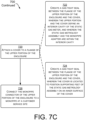
FIGS. 7A ,7B and7C collectively show a flowchart describing a method of converting a diaphragm gas meter into a static gas meter. -
FIG. 8 is a flowchart describing a method of operating a static gas meter. - According to the present invention, a monopipe adapter for a static gas meter is provided as defined in claim 1.
- In a first example, an upper portion of an enclosure of a diaphragm gas meter may be used, repurposed, and/or recycled as an upper portion of the enclosure of a static gas meter. The example is applicable to enclosures used in some, but not all, countries. In a conversion process usable in those countries, a lower portion of the enclosure of the diaphragm gas meter is separated from the upper portion of the enclosure of the diaphragm gas meter. The lower portion of the enclosure contains the diaphragm, and may be discarded in an appropriate manner. The upper portion of the enclosure may be of a type having a monopipe connector having a gas inlet and a gas outlet, and may be used as part of the enclosure of the static gas meter. Depending on the diaphragm gas meter, some components of the diaphragm gas meter may require removal and disposal from the upper portion of the enclosure. The components of the static gas meter may be assembled prior to installation in the upper portion of the enclosure. In the assembly, a downstream end of a static gas metrology assembly can be connected to an upstream end of a monopipe adapter. A downstream end of the monopipe adapter may be connected to the outlet of the monopipe connector of the upper portion of the enclosure. A cover or base-plate may be attached to a flange of the upper portion of the enclosure, thereby sealing the enclosure of the static gas meter in a gas-tight manner.
- In a second example, a static gas meter is contained within an upper portion of the enclosure that was previously part of a diaphragm gas meter. The upper portion of the enclosure includes a monopipe connector having a concentric arrangement (i.e., a pipe-within-a-pipe) with an inlet and an outlet included in the same connector. A flange is disposed about a perimeter of a rim of the upper portion of the enclosure allowing attachment of a cover to the flange of the upper portion of the enclosure, to thereby define a sealed internal cavity forming the enclosure of the static gas meter. In the example, a monopipe adapter has an outlet connected to the outlet of the monopipe connector. An outlet of a static gas metrology assembly is connected to an inlet of the monopipe adapter. In operation, gas flows from an inlet of the monopipe connector into the cavity defined by the enclosure of the static gas meter, enters and flows through the static gas metrology assembly where it is measured, flows through the monopipe adapter, and exits the static gas meter at an outlet of the monopipe connector.
- In a third example, a monopipe adapter is used in a static gas meter, and may include a tubular body having an upstream end and a downstream end. A downstream fastener connects the downstream end of the tubular body to a monopipe connector of the enclosure of the static gas meter. A deflector includes a semicircular sidewall to deflect a portion of a gas flow received through the monopipe connector from a monopipe. A rib defined on an interior of the semicircular sidewall divides an incoming gas flow into a first gas flow and a second gas flow which enter a cavity defined by the enclosure of the static gas meter. A static gas metrology assembly is connected to an upstream fastener of the tubular body of the monopipe adaptor. In operation, the monopipe adapter receives gas flow from the monopipe, and deflects the flow into an interior cavity of the static gas meter. Gas from the interior cavity of the static gas meter enters the static gas metrology assembly where the gas is measured. Gas leaving the static gas metrology assembly flows through the monopipe adapter, exits the static gas meter, and moves into the monopipe.
- The innovations discussed herein save money by reusing part of the existing (and previously approved) enclosure of an older diaphragm-type gas meter. Additionally, such enclosure designs are known and accepted by corporations in the industry, and the connections, interfaces, and closing/sealing technologies are proven to work in the field (e.g., gas customer installation sites). Accordingly, the innovations provide new technology inside the enclosures, while using the proven technology of the existing enclosure components.
-
FIG. 1 is a prior artmechanical gas meter 100 having a mechanical technology involving a movable diaphragm to measure gas flow. Thegas meter 100 is connected to amonopipe 102 using amonopipe connector 104. The monopipe (i.e., a pipe-within-a-pipe) conducts gas into, and out of, themeter 100. Themonopipe connector 104 acts a fastener for both a gas inlet and a gas outlet. Anupper portion 106 of the enclosure of thegas meter 100 may include electronics, auser interface 108, and/or other devices. Alower portion 110 of the gas meter may include a diaphragm configured to measure gas usage by a utility company customer. -
FIGS. 2A and2B shows agas meter 200 having an example of amonopipe adapter 202. Themonopipe adapter 202 is attached to amonopipe connector 204 and to ametrology assembly 206. Themetrology assembly 206 includes ametrology conduit 208, avalve assembly 210, and anupstream fastener assembly 212. Theupstream fastener assembly 212 connects the metrology assembly to themonopipe adapter 202. The upstream fastener assembly is on the "upstream" end of themonopipe adapter 202, which receives gas from themetrology assembly 206. Gas moving through themetrology conduit 208 may be measured using a static gas measuring technology, which may be based on ultrasonic transducers. (Themetrology device 400 of themetrology assembly 206 is seen inFIG. 4 .) Thevalve assembly 210 can be used to turn a gas service to a customer on or off. In the example shown, thevalve assembly 210 prevents the passage of gas leaving themetrology conduit 208 from reaching themonopipe adapter 202. Theupstream fastener assembly 212 allows themetrology assembly 206 to be connected to themonopipe adapter 202. - The
gas meter 200 has anenclosure 214 which includes the upper portion 106 (first seen inFIG. 1 ) taken from adiaphragm gas meter 100. The enclosure has acover 216 or base plate, covering the bottom of the meter. In the example shown, thecover 216 is attached to aflange 218 defined about a lower perimeter of theupper portion 106. - The
monopipe connector 204 is connected to a monopipe having a pipe-within-a-pipe construction. An outer pipe of the monopipe delivers gas to thegas meter 200, while an inner pipe of the monopipe removes gas from the gas meter. An outer pipe delivers gas to apassage 220, from which the gas passes into thegas meter 200. Initially, the gas enters the gas meter in aregion 222 bounded in part by adeflector assembly 224. Thedeflector assembly 224 sends the gas to the right 226. Note that the gas in the flow to the right is outside the kidney-shaped hollowtubular body 228 of themonopipe adapter 202.Gas 230 within the kidney-shaped hollowtubular body 228 is moving to the left 232 toward thepassage 234 through which it will exit thegas meter 200. - The
monopipe connector 204 connects to inner and outer pipes of the monopipe (not shown). The inner pipe of the monopipe seats on an upper surface of annularinner rim 240, while the outer pipe of the monopipe seats on an upper surface of annularouter rim 242. An upper surface of themonopipe adapter 202 is seated in a leak-tight manner to an annular lower surface of therim 240 of the inner pipe of the monopipe connector. In an example, a connectingsurface 236 of themonopipe connector 204 makes a leak-tight seal with a connectingsurface 238 of themonopipe adapter 202. The connectingsurfaces - In operation, gas traveling between the outer pipe of the monopipe and the inner pipe of the monopipe enters the
gas meter 200 atpassage 220. The gas moves intoregion 222 and is redirected by thedeflector assembly 224, causing it to move to the right 226 within the cavity of theenclosure 214. Gas moves within acavity 246 defined by theenclosure 214 and enters anintake port 248 of ametrology conduit 208 or bypass device (if present). (In an example using a bypass device, the gas measured by the metrology assembly may be increased (e.g., doubled, or increased by a factor) to account for the gas traveling through the bypass device. Themetrology device 400 is shown inFIG. 4 .) Gas leaving themetrology conduit 208 passes through anupstream passage 250 of themetrology assembly 206, through thevalve 252 of thevalve assembly 210, and into a downstream passage 254 of themetrology assembly 206. Gas then moves to the left 232 within themonopipe adapter 202. Gas exits thegas meter 200 throughpassage 234 at the downstream end of themonopipe adapter 202, and enters the inner pipe of the monopipe (not shown). -
FIG. 3 shows agas meter 300 having amonopipe adapter 302,monopipe connector 304, andmetrology assembly 306. Themetrology assembly 306 includes a metrology device 308 (shown as a box to represent a variety of metrology assemblies in a non-limiting manner), a valve assembly 310 (shown as a box to represent a variety of valves in a non-limiting manner), and a fastener assembly 312. Themetrology device 308 of themetrology assembly 306 may use any technology (e.g., an ultrasonic technology) indicated by design requirements. - The
valve assembly 310 can be used to enable or disable gas flow to the customer service site. The fastener assembly 312 allows themetrology assembly 306 to be connected to themonopipe adapter 302. - The
gas meter 300 has anenclosure 314 which includes theupper portion 106 that may have been repurposed from a diaphragm gas meter. The enclosure has acover 316 or base plate, covering the bottom of the meter. Thecover 316 may be attached to aflange 318 of theupper portion 106. - The
monopipe connector 304 is connected to a monopipe (not shown). An outer pipe delivers gas to a passage 320-within themonopipe connector 304— from which it flows into thegas meter 300. Initially, the gas enters the gas meter in aregion 322 bounded by adeflector 324. Thedeflector 324 sends the gas to the right 326. Note that the gas is outside thetubular body 328 of themonopipe adapter 302.Gas 330 moving left within thetubular body 328 is moving toward thepassage 332 through which it will exit thegas meter 300. - In an example, the
deflector 324 includes a semicircular sidewall having arib 338 defined on an interior surface of the semicircular sidewall that deflects gas to either side of thetubular body 328 in substantially equal volumes. In an example, therib 338 is centrally located on the interior of the semicircular sidewall of the deflector to divide the incoming gas to flow on both sides of thetubular body 328. - The
monopipe connector 304 has aninner rim 320 that fastens the inner pipe of the monopipe to themonopipe adapter 302. Themonopipe connector 304 is also connected to the outer pipe of the monopipe (not shown). The inner pipe of the monopipe seats onrim 334, while the outer pipe of the monopipe seats onrim 336. Theinner rim 320 and upwardly-facingrims monopipe connector 304. -
FIG. 4 shows amonopipe adapter 202 connected to ametrology assembly 206 by anupstream fastener assembly 212. Themonopipe adapter 202 provides an adaptive connection between the monopipe connector (e.g., themonopipe connector 204 ofFIG. 2A ) and themetrology assembly 206 having ametrology device 400 within an enclosure (e.g.,enclosure 214 shown inFIG. 2A ). Themetrology device 400 of themetrology assembly 206 may use an ultrasonic technology to measure gas flow. Accordingly, themonopipe adapter 202 makes possible the upgrade of mechanical gas meters to static gas meters (e.g., meters having ultrasonic metrology devices) in a more economic manner than was previously possible. In an example, themonopipe adapter 202 allows the reuse of an upper portion of the enclosure of the mechanical gas meter. Themonopipe adapter 202 may also make possible a more cost-effective installation process that does not require modification to existing gas pipes and/or their location(s). - In the example of
FIG. 4 , themonopipe adapter 202 includes adeflector assembly 224 having asemicircular sidewall 402. Thesemicircular sidewall 402 may include therib 338 shown inFIG. 3 . In operation, thedeflector assembly 224 directs a direction of a flow of incoming gas as it enters the gas meter. As shown, thedeflector assembly 224 directs portions of the incoming gas around both sides of the kidney-shaped hollowtubular body 228 of themonopipe adapter 202. Thedeflector assembly 224 may be oriented to direct the gas toward a side of the enclosure that is opposite anintake port 248 of a staticgas metrology assembly 206. - The tubular body includes an
upstream end 404 and adownstream end 406. Theupstream end 404 is connected to themetrology assembly 206 by theupstream fastener assembly 212. The tubular body is configured to have a hollow kidney shape. A side of the tubular body shown in the foreground ofFIG. 4 has a larger-radius curve than a second side of the tubular body shown in the background ofFIG. 4 . - In the example of
FIG. 4 , theupstream fastener assembly 212 includes afirst fastening pin 408 and asecond fastening pin 410 attached to theupstream end 404 of the kidney-shaped hollowtubular body 228 by afirst bracket 412 and a second bracket (obscured by the tubular body on the view ofFIG. 4 ). In the example shown, thefirst fastening pin 408 and thesecond fastening pin 410 are configured to attach to respectivefirst fastener 414 andsecond fastener 416 of adownstream end 418 of the staticgas metrology assembly 206. -
FIG. 5A shows a side view of an example monopipe adapter (e.g.,monopipe adapter 202 seen inFIG. 4 ). Themonopipe adapter 202 includes a kidney-shaped hollowtubular body 228 having anupstream end 404 and adownstream end 406. A connectingsurface 238 of themonopipe adapter 202 is sized to connect to a connectingsurface 236 of the monopipe connector (e.g.,monopipe connector 204 seen inFIG. 2A ). The connection may be made using adhesive, friction, and/or an O-ring, etc. Anupstream fastener assembly 212 is configured to attach themonopipe adapter 202 to metrology device 400 (e.g., as seen inFIG. 4 ). Theupstream fastener assembly 212 includes the fastening pins 408, 410, which engage fasteners of the metrology assembly (e.g.,metrology assembly 206 best seen inFIGS. 2 and4 ). Thedeflector assembly 224 includes thesemicircular sidewall 402. In the drawing,contour lines 500 show the curvature of an outside surface of thesemicircular sidewall 402.Contour line 502 shows curvature of the kidney-shaped hollowtubular body 228. -
FIG. 5B shows a cutaway side view of the example monopipe adapter.Contour lines 504 show curvature of an inside service of the kidney-shaped hollowtubular body 228. Thefastening pin 408, seen in the view ofFIG. 5A , is not seen inFIG. 5B due to the cutaway. -
FIG. 6A shows theupper portion 600 of an example monopipe adapter (e.g.,monopipe adapter 202 seen inFIG. 4 ), whileFIG. 6B shows thelower portion 602 of the monopipe adapter. As seen inFIG. 4 , themonopipe adapter 202 may be configured by connection of anupper portion 600 and thelower portion 602. - A
deflector assembly 224 includes thesemicircular sidewall 402 and the deflectingrib 338.Contour lines 604 show transitions between curvatures of thesemicircular sidewall 402. The kidney-shaped hollowtubular body 228 includes theupstream end 404 and thedownstream end 406. Thedownstream end 406 is closer to the connectingsurface 238 of themonopipe adapter 202 in an area near a passage through which the gas exits themonopipe adapter 202. Theupstream fastener assembly 212 includes the fastening pins 408, 410, supported by afirst bracket 412 andsecond bracket 610, respectively. In the example, the kidney-shaped hollowtubular body 228 includes a number ofcontour lines -
FIG. 6B shows thelower portion 602 of theexample monopipe adapter 202. Thelower portion 602 of the monopipe adapter is seen (but not labeled) inFIG. 4 . -
Contour lines 612 are defined in the bottom surface of thedeflector assembly 224. The contour lines indicate transitions between different curve gradients. - A
gas redirector 614 includes afirst surface 616 and asecond surface 618 that redirect gas flow as it moves out of the kidney-shaped hollowtubular body 228. Accordingly, thegas redirector 614 reduces the friction of the gas flow within the kidney-shaped hollowtubular body 228 and reduces pressure drop within a gas meter using themonopipe adapter 202. -
FIGs. 7A ,7B , and7C (collectively,FIG. 7 ) and associated text describe amethod 700 of converting a diaphragm gas meter into a static gas meter. The diaphragm gas meter represents an older technology, using moving parts, e.g., a diaphragm or bellows. The static gas meter is a newer design, and may use ultrasonic transducers and signal processing without moving parts. An example of themethod 700 for converting a diaphragm gas meter into a static gas meter-that uses some components of the diaphragm gas meter-is described. In an example, a lower portion of the enclosure of the diaphragm gas meter is separated from an upper portion of the enclosure of the diaphragm gas meter. The lower portion of the enclosure contains the diaphragm, and may be discarded appropriately. The upper portion of the enclosure may be of a type having a monopipe connector. The monopipe connector is configured to connect to a monopipe, i.e., a concentric a pipe-within-a-pipe. In the monopipe, gas flows to the meter between the inner and outer pipes, and flows away from the meter in the inner pipe. The monopipe connector includes an inlet and an outlet. Components may be assembled for installation within the upper portion of the enclosure. A static gas metrology assembly is connected to an upstream end of a monopipe adapter. A downstream end of the monopipe adapter may be connected to the outlet of the monopipe connector of the upper portion of the enclosure of the original diaphragm meter. A cover or base-plate may be attached to a flange of the upper portion of the enclosure of the original diaphragm meter. Upon completion of the conversion, the metrology and signal processing of the static gas meter is contained within the upper portion of the original gas meter enclosure, and the lower portion of the original gas meter, components contained therein, along with unneeded components from the upper portion, are discarded. - At
block 702, a lower portion of the enclosure of the diaphragm gas meter is separated from an upper portion of the enclosure of the diaphragm gas meter. As seen in the example ofFIG. 1 , theupper portion 106 of the enclosure of the diaphragm gas meter has amonopipe connector 104 having an inlet and an outlet. By separating theupper portion 106 andlower portion 110 of the enclosure of the diaphragm gas meter, the upper portion of the enclosure and its associated monopipe connector of that portion are available for repurposing. - At
block 704, components of the original diaphragm gas meter within the upper portion of the enclosure may be discarded and/or recycled. The components may include diaphragm gas meter specific metrology equipment. Similarly, in the example ofblock 706, the lower portion of the enclosure and components contained therein, such as the diaphragm metrology equipment, are set aside. - At
block 708, a static gas metrology assembly is connected to an upstream end of a monopipe adapter. Referring to the example ofFIG. 2A , in the convertedstatic gas meter 200, themonopipe adapter 202 will "bridge between" themonopipe connector 204 and to the staticgas metrology assembly 206. The two components (themonopipe adapter 202 and the static gas metrology assembly 206) will reside in theupper portion 106 of the enclosure. In the example ofblock 710, the staticgas metrology assembly 206 is brought into contact with the upstream end of themonopipe adapter 202. In the example ofFIG. 4 , the staticgas metrology assembly 206 is brought into contact with the monopipe adapter and fastened usingfastening assembly 212, including matched pins and brackets. In the example ofblock 712, the static gas metrology assembly is rotated until a first connector element of the static gas metrology assembly connects to a second connector element of the monopipe adapter. In the example ofFIG. 4 , the fastening pins 408, 410 of themonopipe adapter 202 are rotated and latched with thefasteners gas metrology assembly 206 and themonopipe adapter 202, this is just one possibility. Other assembly processes are envisioned. In examples, plastic welding, laser welding, ultrasonic welding, infrared welding, gluing, use of fasteners (e.g., screws, etc.), press-fit, friction-fit, threaded assembly, and other techniques could be used to achieve similar results. - At
block 714, a downstream end of the monopipe adapter is connected to the outlet of the monopipe connector of the upper portion of the enclosure. In the example ofFIG. 4 , the connectingsurface 238 of themonopipe adapter 202 is connected to the connectingsurface 236 of themonopipe connector 204. The connection may be made with glue/adhesive, friction-fit, friction-fit with an O-ring, a threaded connection, etc. In the example ofblock 716, the downstream end of the monopipe adapter is connected to, contacted with, and/or is moved into the proximity of, the outlet of the monopipe connector of the upper portion of the enclosure. In the example ofblock 718, the monopipe adapter and the outlet end of the monopipe connector of the upper portion of the enclosure may be connected using any technology indicated by particular design requirements. In examples themonopipe adapter 202 andmonopipe connector 204 may be attached using glue and/or adhesive, friction fit, friction fit with an O-ring, a threaded connection, and/or any other fastening technology The monopipe adapter is located such that thedeflector assembly 224 directs gas flow toward a side of an interior cavity of the static gas meter that is opposite a side of the interior cavity that is adjacent to anintake port 248 of themetrology conduit 208. - At
block 720, a cover is attached to a flange of the upper portion of the enclosure. In the example ofFIG. 2A , thecover 216 is attached to aflange 218 of theupper portion 106, thereby forming theenclosure 214. In the example ofblock 722, a gas-tight seal is created between the flange of the upper portion of the enclosure and the cover. In the example, theupper portion 106 and thecover 216 define an enclosure having an interior cavity sized to locate the static gas metrology assembly and the monopipe adapter. In the similar example ofblock 724, a gas-tight seal is created between the flange of the upper portion of the enclosure and the cover. In the example, the cover is located to position supporting feet of the static gas metrology assembly on an inner surface of the cover. - At
block 726, the monopipe connector of the upper portion of the enclosure is connected to a monopipe at a customer service site.FIG. 1 shows amonopipe 102 andmonopipe connector 104 to which the monopipe adapter is connected. In the example ofFIG. 2A , connectingsurfaces monopipe connector 204 to themonopipe adapter 202, using glue, friction-fit, an O-ring, threads, etc. -
FIG. 8 shows amethod 800 of operating a static gas meter. Referring to the example ofFIG. 2A , gas traveling between the outer pipe of the monopipe and the inner pipe of the monopipe enters thegas meter 200 atpassage 220. The gas moves into region 222 (which is partially bounded by the deflector assembly 224). The gas is then redirected by thesemicircular sidewall 402 of thedeflector assembly 224, causing it to move to the right 226 within the cavity of theenclosure 214. Gas moves within acavity 246 defined by theenclosure 214 and enters anintake port 248 of ametrology conduit 208 or bypass device (if present). (In an example using a bypass device, the gas measured by the metrology assembly may be increased to account for the gas traveling through the bypass device.) Gas leaving themetrology conduit 208 passes through anupstream passage 250 of themetrology assembly 206, through thevalve 252 of thevalve assembly 210, and into a downstream passage 254 of the metrology assembly. Gas then moves to the left 232 within themonopipe adapter 202. Gas exits thegas meter 200 throughpassage 234 at the downstream end of themonopipe adapter 202, and into the inner pipe of the monopipe (not shown). - At
block 802, a gas flow is received into a monopipe adapter from an upstream portion of a monopipe connector. In the example ofFIG. 2A , gas moves from the region between the inner and outer pipes of the monopipe throughpassage 220, and into aregion 222 that is partially bounded by the semicircular sidewall 402 (labeled inFIG. 4 ) of thedeflector assembly 224. - At
block 804, at least some of the gas flow is deflected using a semicircular sidewall of a deflector of the monopipe adapter. In the examples ofFIGS. 2 and4 , after gas enters theregion 222 it is deflected by thesemicircular sidewall 402 of thedeflector assembly 224. - At
block 806, the gas flow is released into an internal cavity of a sealed enclosure of a static gas meter. In the examples ofFIGS. 2 and4 , having been deflected, gas travels within theinternal cavity 246 of theenclosure 214. - At
block 808, the gas flow is received into a static gas metrology assembly located within the internal cavity. As seen inFIG. 2A , the gas enters anintake port 248 of ametrology conduit 208. As seen inFIG. 4 , gas passing through themetrology conduit 208 may be measured by ametrology device 400, which may use ultrasonic techniques. - At
block 810, the gas flow is sent through the monopipe adapter. In the example ofFIG. 2A , the gas flows to the left 232 through the kidney-shaped hollowtubular body 228 of themonopipe adapter 202. - At
block 812, the gas flow within the monopipe adapter is redirected by operation of a gas redirector defined in a lower interior surface of the kidney-shaped hollow body. As seen inFIG. 6B , theredirector 614 includes two surfaces, which redirect gas upwardly, and out of the kidney-shaped hollowtubular body 228 of themonopipe adapter 202. Theredirector 614 is also seen inFIG. 3 . The gas redirector smooths gas flow, reduces turbulence, and reduces pressure drop within the gas meter. - At
block 814, the gas flow is exhausted to a downstream portion of the monopipe connector. As seen inFIG. 2A , gas passes through thepassage 234 to exit the meter, pass through themonopipe connector 204, and into the monopipe. - Although the subject matter has been described in language specific to structural features and/or methodological acts, it is to be understood that the subject matter defined in the appended claims is not necessarily limited to the specific features or acts described. Rather, the specific features and acts are disclosed as exemplary forms of implementing the claims.
Claims (5)
- A monopipe adapter (202, 302) for a static gas meter (200, 300), comprising:a tubular body (228, 328) having an upstream end (404) and a downstream end (406),
wherein the tubular body (228, 328) comprises a hollow kidney-shaped body having a first side having a larger-radius curve than a second side;a downstream fastener to connect the downstream end (406) of the tubular body (228, 328) to a monopipe connector (204, 304) of an enclosure (214, 314) of the static gas meter;a deflector (224, 324) having a semicircular sidewall (402) to deflect a portion of a gas flow received from a monopipe and through the monopipe connector;a rib (338) defined on an interior of the semicircular sidewall (402) to divide an incoming gas flow into a first gas flow and a second gas flow;an upstream fastener (212) to connect the upstream end (404) of the tubular body (228, 328) to a static gas metrology assembly (206, 306) within the enclosure (214, 314) of the static gas meter. - The monopipe adapter (202) of claim 1, wherein:the upstream fastener (212) is configured to make a rotate-to-lock connection to the static gas metrology assembly (206, 306); andthe downstream fastener is adapted for connection to an outlet of the monopipe connector (204, 304).
- The monopipe adapter (202) of claim 1 or 2, wherein the deflector (224, 324) is oriented to deflect gas in a direction opposite an intake port (248) of a static gas metrology assembly (206).
- The monopipe adapter (202) of any of claims 1 to 3, wherein the rib (338) is centrally located on the interior of the semicircular sidewall (402) to divide the incoming gas flow into substantially equal first and second gas flows.
- The monopipe adapter (202) of any of claims 1 to 4, wherein the upstream fastener (212) comprises:
a first fastening pin (408) and a second fastening pin (410) attached to the upstream end (404) of the tubular body (228), wherein the first fastening pin (408) and the second fastening pin (410) are configured to attach to respective first (414) and second (416) fasteners of a downstream end (418) of the static gas metrology assembly (206).
Priority Applications (3)
| Application Number | Priority Date | Filing Date | Title |
|---|---|---|---|
| EP21173877.8A EP4089375B1 (en) | 2021-05-14 | 2021-05-14 | Monopipe adapter for a gas meter |
| ES21173877T ES2986018T3 (en) | 2021-05-14 | 2021-05-14 | Monotube adapter for gas meter |
| EP24186074.1A EP4421457B1 (en) | 2021-05-14 | 2021-05-14 | Monopipe adapter for a gas meter |
Applications Claiming Priority (1)
| Application Number | Priority Date | Filing Date | Title |
|---|---|---|---|
| EP21173877.8A EP4089375B1 (en) | 2021-05-14 | 2021-05-14 | Monopipe adapter for a gas meter |
Related Child Applications (1)
| Application Number | Title | Priority Date | Filing Date |
|---|---|---|---|
| EP24186074.1A Division EP4421457B1 (en) | 2021-05-14 | 2021-05-14 | Monopipe adapter for a gas meter |
Publications (2)
| Publication Number | Publication Date |
|---|---|
| EP4089375A1 EP4089375A1 (en) | 2022-11-16 |
| EP4089375B1 true EP4089375B1 (en) | 2024-07-03 |
Family
ID=75936748
Family Applications (2)
| Application Number | Title | Priority Date | Filing Date |
|---|---|---|---|
| EP21173877.8A Active EP4089375B1 (en) | 2021-05-14 | 2021-05-14 | Monopipe adapter for a gas meter |
| EP24186074.1A Active EP4421457B1 (en) | 2021-05-14 | 2021-05-14 | Monopipe adapter for a gas meter |
Family Applications After (1)
| Application Number | Title | Priority Date | Filing Date |
|---|---|---|---|
| EP24186074.1A Active EP4421457B1 (en) | 2021-05-14 | 2021-05-14 | Monopipe adapter for a gas meter |
Country Status (2)
| Country | Link |
|---|---|
| EP (2) | EP4089375B1 (en) |
| ES (1) | ES2986018T3 (en) |
Families Citing this family (1)
| Publication number | Priority date | Publication date | Assignee | Title |
|---|---|---|---|---|
| NL2036071B1 (en) * | 2023-10-19 | 2025-05-06 | Liaoning Sc Tech Co Ltd | Integrated ultrasonic gas duct |
Family Cites Families (10)
| Publication number | Priority date | Publication date | Assignee | Title |
|---|---|---|---|---|
| GB810887A (en) * | 1956-12-04 | 1959-03-25 | South Eastern Gas Board | Gas meters |
| CN101126652B (en) * | 2007-09-29 | 2011-03-30 | 重庆前卫仪表厂 | Electronic gas meter for mass and flow |
| DE102010047680A1 (en) * | 2010-10-06 | 2012-04-12 | Hydrometer Gmbh | gas Meter |
| DE102010055116B4 (en) * | 2010-11-16 | 2012-06-21 | Hydrometer Gmbh | gas Meter |
| CN102967335A (en) * | 2012-12-11 | 2013-03-13 | 曲宝源 | Micro-thermal type fuel gas meter |
| JP6263738B2 (en) * | 2014-02-07 | 2018-01-24 | パナソニックIpマネジメント株式会社 | Gas flow meter |
| US9784607B2 (en) * | 2016-02-24 | 2017-10-10 | M-Tech Instrument Corporation Holding Limited | Utility mass flow gas meter |
| US10520344B2 (en) * | 2017-04-20 | 2019-12-31 | Itron, Inc. | Proportional flow comparative metering |
| WO2020097515A1 (en) * | 2018-11-10 | 2020-05-14 | Itron Global Sarl | Gas meter and particle trap |
| CN212871327U (en) * | 2020-08-20 | 2021-04-02 | 上海真兰仪表科技股份有限公司 | Gas outlet pipe structure of single-pipe gas meter |
-
2021
- 2021-05-14 ES ES21173877T patent/ES2986018T3/en active Active
- 2021-05-14 EP EP21173877.8A patent/EP4089375B1/en active Active
- 2021-05-14 EP EP24186074.1A patent/EP4421457B1/en active Active
Also Published As
| Publication number | Publication date |
|---|---|
| EP4421457A3 (en) | 2024-11-20 |
| EP4421457B1 (en) | 2026-07-15 |
| EP4421457A2 (en) | 2024-08-28 |
| ES2986018T3 (en) | 2024-11-08 |
| EP4089375A1 (en) | 2022-11-16 |
Similar Documents
| Publication | Publication Date | Title |
|---|---|---|
| JPH1030946A (en) | Apparatus for measuring fluid flow | |
| US4375365A (en) | Centrifugal chamber filter for separating solids from a gas stream | |
| US5616841A (en) | Flow metering device for landfill gas extraction well | |
| CA1100333A (en) | Remotely controlled retractable insertion flowmeter | |
| EP4421457A2 (en) | Monopipe adapter for a gas meter | |
| CN113227589B (en) | Corner fitting for fluidly connecting fluid lines of a vehicle | |
| US2881012A (en) | Pipe line connections for meters and the like | |
| US9068421B2 (en) | Molded well head cover | |
| JP2014046289A (en) | Gas filter device | |
| JPS61145350A (en) | Pressure controller | |
| EP1333254B1 (en) | Sensor manifold for a flow sensing venturi | |
| CN104049042B (en) | There is the process analytical instrument that the flame cancellation of closing connects | |
| JP2002081976A (en) | Restriction structure of differential pressure type flow meter | |
| CN204027615U (en) | Flowmeter shell and flowmeter | |
| US20140000375A1 (en) | Pressure sensor assembly | |
| CN108374921A (en) | A kind of fluid line pressure relief assembly and fluid line | |
| CN111911316B (en) | Integrated propellant control system for gas-liquid bipropellant rocket engines | |
| FR3137349B1 (en) | Device for cleaning an optical surface | |
| CN105222838A (en) | Flowmeter shell and flowmeter | |
| US8438933B2 (en) | Flowmeter and manifold therefor | |
| JP2868970B2 (en) | Rectifier | |
| CN219869817U (en) | Flow sensor with replaceable flow channel | |
| CN217687352U (en) | Compact flow passage structure of gas ultrasonic flowmeter | |
| CN103591989B (en) | Petroleum gas wafer type conical pipe flowmeter | |
| CN222910149U (en) | Intake manifold with side air intake |
Legal Events
| Date | Code | Title | Description |
|---|---|---|---|
| PUAI | Public reference made under article 153(3) epc to a published international application that has entered the european phase |
Free format text: ORIGINAL CODE: 0009012 |
|
| STAA | Information on the status of an ep patent application or granted ep patent |
Free format text: STATUS: THE APPLICATION HAS BEEN PUBLISHED |
|
| AK | Designated contracting states |
Kind code of ref document: A1 Designated state(s): AL AT BE BG CH CY CZ DE DK EE ES FI FR GB GR HR HU IE IS IT LI LT LU LV MC MK MT NL NO PL PT RO RS SE SI SK SM TR |
|
| STAA | Information on the status of an ep patent application or granted ep patent |
Free format text: STATUS: REQUEST FOR EXAMINATION WAS MADE |
|
| 17P | Request for examination filed |
Effective date: 20230516 |
|
| RBV | Designated contracting states (corrected) |
Designated state(s): AL AT BE BG CH CY CZ DE DK EE ES FI FR GB GR HR HU IE IS IT LI LT LU LV MC MK MT NL NO PL PT RO RS SE SI SK SM TR |
|
| P01 | Opt-out of the competence of the unified patent court (upc) registered |
Effective date: 20230519 |
|
| GRAP | Despatch of communication of intention to grant a patent |
Free format text: ORIGINAL CODE: EPIDOSNIGR1 |
|
| STAA | Information on the status of an ep patent application or granted ep patent |
Free format text: STATUS: GRANT OF PATENT IS INTENDED |
|
| RIC1 | Information provided on ipc code assigned before grant |
Ipc: G01F 3/22 20060101ALN20231221BHEP Ipc: G01F 1/66 20220101ALI20231221BHEP Ipc: G01F 15/14 20060101ALI20231221BHEP Ipc: G01F 15/18 20060101AFI20231221BHEP |
|
| INTG | Intention to grant announced |
Effective date: 20240122 |
|
| GRAS | Grant fee paid |
Free format text: ORIGINAL CODE: EPIDOSNIGR3 |
|
| GRAA | (expected) grant |
Free format text: ORIGINAL CODE: 0009210 |
|
| STAA | Information on the status of an ep patent application or granted ep patent |
Free format text: STATUS: THE PATENT HAS BEEN GRANTED |
|
| AK | Designated contracting states |
Kind code of ref document: B1 Designated state(s): AL AT BE BG CH CY CZ DE DK EE ES FI FR GB GR HR HU IE IS IT LI LT LU LV MC MK MT NL NO PL PT RO RS SE SI SK SM TR |
|
| REG | Reference to a national code |
Ref country code: CH Ref legal event code: EP |
|
| REG | Reference to a national code |
Ref country code: DE Ref legal event code: R096 Ref document number: 602021015023 Country of ref document: DE |
|
| REG | Reference to a national code |
Ref country code: LT Ref legal event code: MG9D |
|
| REG | Reference to a national code |
Ref country code: NL Ref legal event code: MP Effective date: 20240703 |
|
| REG | Reference to a national code |
Ref country code: ES Ref legal event code: FG2A Ref document number: 2986018 Country of ref document: ES Kind code of ref document: T3 Effective date: 20241108 |
|
| PG25 | Lapsed in a contracting state [announced via postgrant information from national office to epo] |
Ref country code: PT Free format text: LAPSE BECAUSE OF FAILURE TO SUBMIT A TRANSLATION OF THE DESCRIPTION OR TO PAY THE FEE WITHIN THE PRESCRIBED TIME-LIMIT Effective date: 20241104 |
|
| REG | Reference to a national code |
Ref country code: AT Ref legal event code: MK05 Ref document number: 1700248 Country of ref document: AT Kind code of ref document: T Effective date: 20240703 |
|
| PG25 | Lapsed in a contracting state [announced via postgrant information from national office to epo] |
Ref country code: NL Free format text: LAPSE BECAUSE OF FAILURE TO SUBMIT A TRANSLATION OF THE DESCRIPTION OR TO PAY THE FEE WITHIN THE PRESCRIBED TIME-LIMIT Effective date: 20240703 |
|
| PG25 | Lapsed in a contracting state [announced via postgrant information from national office to epo] |
Ref country code: PT Free format text: LAPSE BECAUSE OF FAILURE TO SUBMIT A TRANSLATION OF THE DESCRIPTION OR TO PAY THE FEE WITHIN THE PRESCRIBED TIME-LIMIT Effective date: 20241104 Ref country code: NL Free format text: LAPSE BECAUSE OF FAILURE TO SUBMIT A TRANSLATION OF THE DESCRIPTION OR TO PAY THE FEE WITHIN THE PRESCRIBED TIME-LIMIT Effective date: 20240703 |
|
| PG25 | Lapsed in a contracting state [announced via postgrant information from national office to epo] |
Ref country code: NO Free format text: LAPSE BECAUSE OF FAILURE TO SUBMIT A TRANSLATION OF THE DESCRIPTION OR TO PAY THE FEE WITHIN THE PRESCRIBED TIME-LIMIT Effective date: 20241003 |
|
| PG25 | Lapsed in a contracting state [announced via postgrant information from national office to epo] |
Ref country code: FI Free format text: LAPSE BECAUSE OF FAILURE TO SUBMIT A TRANSLATION OF THE DESCRIPTION OR TO PAY THE FEE WITHIN THE PRESCRIBED TIME-LIMIT Effective date: 20240703 Ref country code: GR Free format text: LAPSE BECAUSE OF FAILURE TO SUBMIT A TRANSLATION OF THE DESCRIPTION OR TO PAY THE FEE WITHIN THE PRESCRIBED TIME-LIMIT Effective date: 20241004 Ref country code: PL Free format text: LAPSE BECAUSE OF FAILURE TO SUBMIT A TRANSLATION OF THE DESCRIPTION OR TO PAY THE FEE WITHIN THE PRESCRIBED TIME-LIMIT Effective date: 20240703 |
|
| PG25 | Lapsed in a contracting state [announced via postgrant information from national office to epo] |
Ref country code: BG Free format text: LAPSE BECAUSE OF FAILURE TO SUBMIT A TRANSLATION OF THE DESCRIPTION OR TO PAY THE FEE WITHIN THE PRESCRIBED TIME-LIMIT Effective date: 20240703 |
|
| PG25 | Lapsed in a contracting state [announced via postgrant information from national office to epo] |
Ref country code: LV Free format text: LAPSE BECAUSE OF FAILURE TO SUBMIT A TRANSLATION OF THE DESCRIPTION OR TO PAY THE FEE WITHIN THE PRESCRIBED TIME-LIMIT Effective date: 20240703 |
|
| PG25 | Lapsed in a contracting state [announced via postgrant information from national office to epo] |
Ref country code: IS Free format text: LAPSE BECAUSE OF FAILURE TO SUBMIT A TRANSLATION OF THE DESCRIPTION OR TO PAY THE FEE WITHIN THE PRESCRIBED TIME-LIMIT Effective date: 20241103 Ref country code: AT Free format text: LAPSE BECAUSE OF FAILURE TO SUBMIT A TRANSLATION OF THE DESCRIPTION OR TO PAY THE FEE WITHIN THE PRESCRIBED TIME-LIMIT Effective date: 20240703 |
|
| PG25 | Lapsed in a contracting state [announced via postgrant information from national office to epo] |
Ref country code: CZ Free format text: LAPSE BECAUSE OF FAILURE TO SUBMIT A TRANSLATION OF THE DESCRIPTION OR TO PAY THE FEE WITHIN THE PRESCRIBED TIME-LIMIT Effective date: 20240703 Ref country code: HR Free format text: LAPSE BECAUSE OF FAILURE TO SUBMIT A TRANSLATION OF THE DESCRIPTION OR TO PAY THE FEE WITHIN THE PRESCRIBED TIME-LIMIT Effective date: 20240703 |
|
| PG25 | Lapsed in a contracting state [announced via postgrant information from national office to epo] |
Ref country code: RS Free format text: LAPSE BECAUSE OF FAILURE TO SUBMIT A TRANSLATION OF THE DESCRIPTION OR TO PAY THE FEE WITHIN THE PRESCRIBED TIME-LIMIT Effective date: 20241003 |
|
| PG25 | Lapsed in a contracting state [announced via postgrant information from national office to epo] |
Ref country code: RS Free format text: LAPSE BECAUSE OF FAILURE TO SUBMIT A TRANSLATION OF THE DESCRIPTION OR TO PAY THE FEE WITHIN THE PRESCRIBED TIME-LIMIT Effective date: 20241003 Ref country code: PL Free format text: LAPSE BECAUSE OF FAILURE TO SUBMIT A TRANSLATION OF THE DESCRIPTION OR TO PAY THE FEE WITHIN THE PRESCRIBED TIME-LIMIT Effective date: 20240703 Ref country code: NO Free format text: LAPSE BECAUSE OF FAILURE TO SUBMIT A TRANSLATION OF THE DESCRIPTION OR TO PAY THE FEE WITHIN THE PRESCRIBED TIME-LIMIT Effective date: 20241003 Ref country code: LV Free format text: LAPSE BECAUSE OF FAILURE TO SUBMIT A TRANSLATION OF THE DESCRIPTION OR TO PAY THE FEE WITHIN THE PRESCRIBED TIME-LIMIT Effective date: 20240703 Ref country code: IS Free format text: LAPSE BECAUSE OF FAILURE TO SUBMIT A TRANSLATION OF THE DESCRIPTION OR TO PAY THE FEE WITHIN THE PRESCRIBED TIME-LIMIT Effective date: 20241103 Ref country code: HR Free format text: LAPSE BECAUSE OF FAILURE TO SUBMIT A TRANSLATION OF THE DESCRIPTION OR TO PAY THE FEE WITHIN THE PRESCRIBED TIME-LIMIT Effective date: 20240703 Ref country code: GR Free format text: LAPSE BECAUSE OF FAILURE TO SUBMIT A TRANSLATION OF THE DESCRIPTION OR TO PAY THE FEE WITHIN THE PRESCRIBED TIME-LIMIT Effective date: 20241004 Ref country code: FI Free format text: LAPSE BECAUSE OF FAILURE TO SUBMIT A TRANSLATION OF THE DESCRIPTION OR TO PAY THE FEE WITHIN THE PRESCRIBED TIME-LIMIT Effective date: 20240703 Ref country code: CZ Free format text: LAPSE BECAUSE OF FAILURE TO SUBMIT A TRANSLATION OF THE DESCRIPTION OR TO PAY THE FEE WITHIN THE PRESCRIBED TIME-LIMIT Effective date: 20240703 Ref country code: BG Free format text: LAPSE BECAUSE OF FAILURE TO SUBMIT A TRANSLATION OF THE DESCRIPTION OR TO PAY THE FEE WITHIN THE PRESCRIBED TIME-LIMIT Effective date: 20240703 Ref country code: AT Free format text: LAPSE BECAUSE OF FAILURE TO SUBMIT A TRANSLATION OF THE DESCRIPTION OR TO PAY THE FEE WITHIN THE PRESCRIBED TIME-LIMIT Effective date: 20240703 |
|
| REG | Reference to a national code |
Ref country code: DE Ref legal event code: R097 Ref document number: 602021015023 Country of ref document: DE |
|
| PG25 | Lapsed in a contracting state [announced via postgrant information from national office to epo] |
Ref country code: DK Free format text: LAPSE BECAUSE OF FAILURE TO SUBMIT A TRANSLATION OF THE DESCRIPTION OR TO PAY THE FEE WITHIN THE PRESCRIBED TIME-LIMIT Effective date: 20240703 Ref country code: SM Free format text: LAPSE BECAUSE OF FAILURE TO SUBMIT A TRANSLATION OF THE DESCRIPTION OR TO PAY THE FEE WITHIN THE PRESCRIBED TIME-LIMIT Effective date: 20240703 Ref country code: RO Free format text: LAPSE BECAUSE OF FAILURE TO SUBMIT A TRANSLATION OF THE DESCRIPTION OR TO PAY THE FEE WITHIN THE PRESCRIBED TIME-LIMIT Effective date: 20240703 |
|
| PG25 | Lapsed in a contracting state [announced via postgrant information from national office to epo] |
Ref country code: EE Free format text: LAPSE BECAUSE OF FAILURE TO SUBMIT A TRANSLATION OF THE DESCRIPTION OR TO PAY THE FEE WITHIN THE PRESCRIBED TIME-LIMIT Effective date: 20240703 |
|
| PG25 | Lapsed in a contracting state [announced via postgrant information from national office to epo] |
Ref country code: SK Free format text: LAPSE BECAUSE OF FAILURE TO SUBMIT A TRANSLATION OF THE DESCRIPTION OR TO PAY THE FEE WITHIN THE PRESCRIBED TIME-LIMIT Effective date: 20240703 |
|
| PLBE | No opposition filed within time limit |
Free format text: ORIGINAL CODE: 0009261 |
|
| STAA | Information on the status of an ep patent application or granted ep patent |
Free format text: STATUS: NO OPPOSITION FILED WITHIN TIME LIMIT |
|
| 26N | No opposition filed |
Effective date: 20250404 |
|
| PG25 | Lapsed in a contracting state [announced via postgrant information from national office to epo] |
Ref country code: SE Free format text: LAPSE BECAUSE OF FAILURE TO SUBMIT A TRANSLATION OF THE DESCRIPTION OR TO PAY THE FEE WITHIN THE PRESCRIBED TIME-LIMIT Effective date: 20240703 |
|
| REG | Reference to a national code |
Ref country code: CH Ref legal event code: H13 Free format text: ST27 STATUS EVENT CODE: U-0-0-H10-H13 (AS PROVIDED BY THE NATIONAL OFFICE) Effective date: 20251223 |
|
| PG25 | Lapsed in a contracting state [announced via postgrant information from national office to epo] |
Ref country code: LU Free format text: LAPSE BECAUSE OF NON-PAYMENT OF DUE FEES Effective date: 20250514 |
|
| PG25 | Lapsed in a contracting state [announced via postgrant information from national office to epo] |
Ref country code: CH Free format text: LAPSE BECAUSE OF NON-PAYMENT OF DUE FEES Effective date: 20250531 |
|
| REG | Reference to a national code |
Ref country code: BE Ref legal event code: MM Effective date: 20250531 |
|
| PG25 | Lapsed in a contracting state [announced via postgrant information from national office to epo] |
Ref country code: MC Free format text: LAPSE BECAUSE OF FAILURE TO SUBMIT A TRANSLATION OF THE DESCRIPTION OR TO PAY THE FEE WITHIN THE PRESCRIBED TIME-LIMIT Effective date: 20240703 |
|
| PGFP | Annual fee paid to national office [announced via postgrant information from national office to epo] |
Ref country code: GB Payment date: 20260312 Year of fee payment: 6 |
|
| PG25 | Lapsed in a contracting state [announced via postgrant information from national office to epo] |
Ref country code: IE Free format text: LAPSE BECAUSE OF NON-PAYMENT OF DUE FEES Effective date: 20250514 |
|
| PG25 | Lapsed in a contracting state [announced via postgrant information from national office to epo] |
Ref country code: BE Free format text: LAPSE BECAUSE OF NON-PAYMENT OF DUE FEES Effective date: 20250531 |
|
| PGFP | Annual fee paid to national office [announced via postgrant information from national office to epo] |
Ref country code: FR Payment date: 20260309 Year of fee payment: 6 |
|
| PG25 | Lapsed in a contracting state [announced via postgrant information from national office to epo] |
Ref country code: LT Free format text: LAPSE BECAUSE OF FAILURE TO SUBMIT A TRANSLATION OF THE DESCRIPTION OR TO PAY THE FEE WITHIN THE PRESCRIBED TIME-LIMIT Effective date: 20240703 |
|
| PGFP | Annual fee paid to national office [announced via postgrant information from national office to epo] |
Ref country code: ES Payment date: 20260610 Year of fee payment: 6 |
|
| PGFP | Annual fee paid to national office [announced via postgrant information from national office to epo] |
Ref country code: IT Payment date: 20260422 Year of fee payment: 6 |
|
| PGFP | Annual fee paid to national office [announced via postgrant information from national office to epo] |
Ref country code: DE Payment date: 20260317 Year of fee payment: 6 |
|
| PG25 | Lapsed in a contracting state [announced via postgrant information from national office to epo] |
Ref country code: CY Free format text: LAPSE BECAUSE OF FAILURE TO SUBMIT A TRANSLATION OF THE DESCRIPTION OR TO PAY THE FEE WITHIN THE PRESCRIBED TIME-LIMIT Effective date: 20240703 |