EP4089353A1 - Refrigerator - Google Patents
Refrigerator Download PDFInfo
- Publication number
- EP4089353A1 EP4089353A1 EP20912164.9A EP20912164A EP4089353A1 EP 4089353 A1 EP4089353 A1 EP 4089353A1 EP 20912164 A EP20912164 A EP 20912164A EP 4089353 A1 EP4089353 A1 EP 4089353A1
- Authority
- EP
- European Patent Office
- Prior art keywords
- cover
- panel
- display
- fixing
- cabinet
- Prior art date
- Legal status (The legal status is an assumption and is not a legal conclusion. Google has not performed a legal analysis and makes no representation as to the accuracy of the status listed.)
- Granted
Links
Images










Classifications
-
- F—MECHANICAL ENGINEERING; LIGHTING; HEATING; WEAPONS; BLASTING
- F25—REFRIGERATION OR COOLING; COMBINED HEATING AND REFRIGERATION SYSTEMS; HEAT PUMP SYSTEMS; MANUFACTURE OR STORAGE OF ICE; LIQUEFACTION SOLIDIFICATION OF GASES
- F25D—REFRIGERATORS; COLD ROOMS; ICE-BOXES; COOLING OR FREEZING APPARATUS NOT OTHERWISE PROVIDED FOR
- F25D23/00—General constructional features
- F25D23/06—Walls
- F25D23/062—Walls defining a cabinet
- F25D23/063—Walls defining a cabinet formed by an assembly of panels
-
- F—MECHANICAL ENGINEERING; LIGHTING; HEATING; WEAPONS; BLASTING
- F25—REFRIGERATION OR COOLING; COMBINED HEATING AND REFRIGERATION SYSTEMS; HEAT PUMP SYSTEMS; MANUFACTURE OR STORAGE OF ICE; LIQUEFACTION SOLIDIFICATION OF GASES
- F25D—REFRIGERATORS; COLD ROOMS; ICE-BOXES; COOLING OR FREEZING APPARATUS NOT OTHERWISE PROVIDED FOR
- F25D23/00—General constructional features
- F25D23/10—Arrangements for mounting in particular locations, e.g. for built-in type, for corner type
-
- F—MECHANICAL ENGINEERING; LIGHTING; HEATING; WEAPONS; BLASTING
- F25—REFRIGERATION OR COOLING; COMBINED HEATING AND REFRIGERATION SYSTEMS; HEAT PUMP SYSTEMS; MANUFACTURE OR STORAGE OF ICE; LIQUEFACTION SOLIDIFICATION OF GASES
- F25D—REFRIGERATORS; COLD ROOMS; ICE-BOXES; COOLING OR FREEZING APPARATUS NOT OTHERWISE PROVIDED FOR
- F25D11/00—Self-contained movable devices, e.g. domestic refrigerators
-
- F—MECHANICAL ENGINEERING; LIGHTING; HEATING; WEAPONS; BLASTING
- F25—REFRIGERATION OR COOLING; COMBINED HEATING AND REFRIGERATION SYSTEMS; HEAT PUMP SYSTEMS; MANUFACTURE OR STORAGE OF ICE; LIQUEFACTION SOLIDIFICATION OF GASES
- F25D—REFRIGERATORS; COLD ROOMS; ICE-BOXES; COOLING OR FREEZING APPARATUS NOT OTHERWISE PROVIDED FOR
- F25D23/00—General constructional features
- F25D23/02—Doors; Covers
-
- F—MECHANICAL ENGINEERING; LIGHTING; HEATING; WEAPONS; BLASTING
- F25—REFRIGERATION OR COOLING; COMBINED HEATING AND REFRIGERATION SYSTEMS; HEAT PUMP SYSTEMS; MANUFACTURE OR STORAGE OF ICE; LIQUEFACTION SOLIDIFICATION OF GASES
- F25D—REFRIGERATORS; COLD ROOMS; ICE-BOXES; COOLING OR FREEZING APPARATUS NOT OTHERWISE PROVIDED FOR
- F25D23/00—General constructional features
- F25D23/06—Walls
- F25D23/065—Details
- F25D23/067—Supporting elements
-
- F—MECHANICAL ENGINEERING; LIGHTING; HEATING; WEAPONS; BLASTING
- F25—REFRIGERATION OR COOLING; COMBINED HEATING AND REFRIGERATION SYSTEMS; HEAT PUMP SYSTEMS; MANUFACTURE OR STORAGE OF ICE; LIQUEFACTION SOLIDIFICATION OF GASES
- F25D—REFRIGERATORS; COLD ROOMS; ICE-BOXES; COOLING OR FREEZING APPARATUS NOT OTHERWISE PROVIDED FOR
- F25D29/00—Arrangement or mounting of control or safety devices
- F25D29/005—Mounting of control devices
-
- F—MECHANICAL ENGINEERING; LIGHTING; HEATING; WEAPONS; BLASTING
- F25—REFRIGERATION OR COOLING; COMBINED HEATING AND REFRIGERATION SYSTEMS; HEAT PUMP SYSTEMS; MANUFACTURE OR STORAGE OF ICE; LIQUEFACTION SOLIDIFICATION OF GASES
- F25D—REFRIGERATORS; COLD ROOMS; ICE-BOXES; COOLING OR FREEZING APPARATUS NOT OTHERWISE PROVIDED FOR
- F25D2400/00—General features of, or devices for refrigerators, cold rooms, ice-boxes, or for cooling or freezing apparatus not covered by any other subclass
- F25D2400/08—Refrigerator tables
-
- F—MECHANICAL ENGINEERING; LIGHTING; HEATING; WEAPONS; BLASTING
- F25—REFRIGERATION OR COOLING; COMBINED HEATING AND REFRIGERATION SYSTEMS; HEAT PUMP SYSTEMS; MANUFACTURE OR STORAGE OF ICE; LIQUEFACTION SOLIDIFICATION OF GASES
- F25D—REFRIGERATORS; COLD ROOMS; ICE-BOXES; COOLING OR FREEZING APPARATUS NOT OTHERWISE PROVIDED FOR
- F25D2400/00—General features of, or devices for refrigerators, cold rooms, ice-boxes, or for cooling or freezing apparatus not covered by any other subclass
- F25D2400/36—Visual displays
Definitions
- the present invention relates to a refrigerator.
- refrigerators are household appliances that are capable of store objects such as foods at a low temperature in a storage space provided in a cabinet. Since the storage space is surrounded by heat insulation wall, the inside of the storage space may be maintained at a temperature less than an external temperature.
- the storage space may be classified into a refrigerating compartment or a freezing compartment according to a temperature range of the storage space.
- the food may be stored in the refrigerating compartment or the freezing compartment according to the type or condition of the food.
- the refrigerator may be provided as a built-in type together with other electronic devices in the kitchen. In this case, a design in outer appearance of the refrigerator is performed in harmony with the furniture in the kitchen.
- the design of the outer appearance of the refrigerator is performed so that the outer appearance of the refrigerator is harmonized with the furniture in a space in which the refrigerator is installed.
- the outer appearance of the refrigerator may be designed to be made of wood to be harmonized with the furniture made of wood.
- a refrigerator in which a furniture door and a refrigerator door, which are made of wood, are screw-coupled to each other, is disclosed in Korean Patent Publication No. 10-2004-0003319 , which is a prior art document.
- the outer appearance made of the wood material may be damaged by moisture or the like when used for a long period of time and may require service such as replacement.
- An object of the present invention is to provide a refrigerator in which a cabinet cover made of a wood material is easily disassembled.
- an object of the present invention is to provide a refrigerator in which a cabinet cover is easily disassembled without disassembling a rear panel disposed at a rear side from a cabinet.
- an object of the present invention is to provide a refrigerator in which a display unit disposed at a rear side of a cabinet cover is easily separated from a cabinet.
- an object of the present invention is to provide a refrigerator in which a time required for replacing and reassembling a cabinet cover is saved.
- a refrigerator for achieving the above objects includes: a cabinet provided with a storage space and including a pair of side panels configured to define an outer appearance of a side surface; a cabinet cover disposed between the pair of side panels and configured to define an outer appearance of a top surface; a display unit disposed behind the cabinet cover and provided for user's manipulation; and a fixing unit which is fixed to the cabinet and disposed between the pair of side panels and to which the display unit is separably fixed, wherein the display unit is installed to be separated upward from the fixing unit. Therefore, there may be an advantage in that it is easy to separate the display unit from the cabinet.
- the cabinet cover may be detached backward in a state of being separated from the display unit. Therefore, as the display unit is easily separated, the cabinet cover may be easily and quickly separated from the cabinet.
- the fixing unit may include a fixing protrusion, and a protrusion accommodation portion, in which the fixing protrusion is accommodated, may be provided in the display unit.
- the fixing unit may further include a first body disposed to face the side panels, and the fixing protrusion protrudes from the first body.
- the refrigerator may further include: an inner case configured to define the storage space; and a middle plate configured to cover an outer circumference of the inner case, wherein the fixing unit may further include a second body bent from the first body to face the middle plate.
- the first body may be coupled to the side panels, and the second body may be coupled to the middle plate. Therefore, the fixing unit may facilitate the separation of the display unit and firmly couple the side panel and the middle plate to each other.
- the first body may be coupled to the side panels, or the second body may be coupled to the middle plate.
- the middle plate may include a rear plate disposed between the inner case and the rear panel, and the second body may be coupled to the rear plate.
- the fixing protrusion may be provided in plurality, and the plurality of fixing protrusions may protrude from top and bottom surfaces of the first body.
- the cabinet may further include: an inner case configured to define the storage space; and a middle plate configured to cover an outer circumference of the inner case
- the fixing unit may include: a first body disposed to face the side panels; and a second body bent from the first body to face the middle plate, and the fixing protrusion may protrude from the second body.
- the refrigerator may further include a rear panel configured to constitute the cabinet and define an outer appearance of a rear surface, wherein the display unit may further include a panel seating portion seated on the rear panel.
- a bolt coupling hole through which a bolt is coupled to restrict vertical movement of the display unit may be defined in each of the panel seating portion and the rear panel.
- the display unit may include: a display case above which a display panel is provided; and a display cover configured to cover the display panel and rotatably coupled to the display case, wherein the protrusion accommodation portion may be disposed on a side surface portion of the display case.
- the protrusion accommodation portion may be recessed upward from a bottom surface of the side surface portion.
- the fixing protrusion may have a thickness greater than that of the side surface portion.
- the fixing protrusion may have the same height as the protrusion accommodation portion so that a bottom surface of the side surface portion is seated on a top surface of the first body.
- a seating groove recessed downward from an upper end of the side surface portion may be defined in the display case
- the display cover may include: a cover plate configured to cover an upper side of the display panel; and a pair of extension portions extending downward from both ends of the cover plate and rotatably coupled to the seating groove, and wherein the seating groove may be disposed behind the protrusion accommodation portion.
- the cabinet cover made of wood may be easily separated to save the required time.
- the cabinet cover and the display unit are separated without disassembling the rear panel from the main body (cabinet), there may be the effect that the reassembly process after the service is simplified.
- the assembly process since the display unit is mounted to the cabinet by the fixing unit, the assembly process may be simplified in production process to improve the productivity.
- the display unit when the screw of the rear panel that fixes the display unit is released, the display unit may be lifted upward to be separated, and the cabinet cover may be easily separated backward.
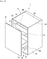
- FIG. 1 is a perspective view of a refrigerator according to an embodiment of the present invention
- FIG. 2 is a perspective view illustrating a state in which a door is opened in FIG. 1
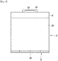
- FIG. 3 is a plan view of the refrigerator of FIG. 1 .
- a refrigerator 1 may include a cabinet 10 provided with a storage space 111 and a door 20 connected to the cabinet 10 to open and close the storage space 111.
- the cabinet 10 may include an inner case 110 defining the storage space 111 and an outer case 100 surrounding the inner case 110.
- the outer case 100 may be made of a metal material.
- the outer case 100 may be made of an aluminum (Al) material.
- the outer case 100 may be formed by being bent at least twice or bent.
- the outer case 100 may be formed by bonding a plurality of metal plates.
- the outer case 100 may include a pair of side panels 102 and 103.
- the pair of side panels 102 and 103 may be arranged in a horizontal direction.
- the side panels 102 and 103 may include a right side panel 102 and a left side panel 103 with respect to on a direction that is directed from the door 20 to the storage space 111.
- a direction that is directed from the door 20 to the storage space 111 may be defined as "a rear side”, and a direction that is directed from the storage space 111 to the door 20 may be defined as a "front side”. That is, the storage space 111 may be disposed at the rear side of the door 20.
- the inner case 110 may be directly or indirectly fixed to the outer case 100 in a state of being disposed between the pair of side panels 102 and 103.
- a front end 102a of each of the pair of side panels 102 and 103 may be disposed in front of the front surface of the inner case 110, rather than a front surface of the inner case 110.
- a horizontal width of the door 20 may be equal to or less than a distance between the pair of side panels 102 and 103.
- a space in which the door 20 is disposed may be defined between the pair of side panels 102 and 103.
- the door 20 may be disposed between the pair of side panels 102 and 103.
- the front surface of the door 20 may be disposed on the same plane as the front end of each of the side panels 102 and 103 so that the outer appearances of the door 20 and the cabinet 10 have a sense of unity.
- the front surface of the door 20 and the front end 102a of each of the side panels 102 and 103 may define the outer appearance of the front surface of the refrigerator 1.
- the door 20 may be connected to, for example, the cabinet 10 by a rail assembly 90.
- the door 20 may open and close the storage space 111 while moving in a forward and backward sliding manner in a state of being connected to the cabinet 10.
- the door 20 even when the refrigerator 1 is disposed in a narrow space such as a kitchen, living room, or room, since the door 20 opens and closes the storage space 111 in the sliding manner, the door 20 may be opened without interfering with surrounding structures.
- One side of the rail assembly 90 may be connected to the door 20, and the other side may be connected to the inner case 110.
- the door 20 may include a front panel 210 made of a wood material and a door liner 230 coupled to a rear surface of the front panel 210.
- the front panel 210 and the door liner 230 may be coupled to each other by, for example, a coupling member such as a screw.
- the front panel 210 and the door liner 230 may define a foaming space, and as a foaming liquid is filled in the foaming space, an insulating material may be provided between the front panel 210 and the door liner 230.
- the door 20 may define a space 290 for a handle into which a user's hand is inserted so that the user holds the door 20.
- the space 290 for the handle may be defined, for example, as a portion of an upper portion of the door liner 230 is recessed downward.
- the space 290 for the handle may be disposed between the front panel 210 and the cabinet 10 in a state in which the door 20 closes the storage space 111.
- the user may open the door 20 by pulling the door 20 after inserting the hand into the space 290 for the handle 290 in the state in which the door 20 closes the storage space 111.
- the aesthetics of the refrigerator 1 may be improved.
- a height of the refrigerator 1 is not limited, but may be less than that of a general adult. As a capacity of the refrigerator 1 decreases, the height of the refrigerator 1 may decrease.
- the space 290 for the handle 290 exists above the door 20, even if the height of the refrigerator 1 decreases, the user may easily open the door 20 in a standing or sit state.
- each of the pair of side panels 102 and 103 may be disposed higher than an upper end of the inner case 110.
- a space may be defined above the inner case 110, and a cabinet cover 190 may be disposed in the space.
- the cabinet cover 190 may define an outer appearance of a top surface of the cabinet 10. That is, the cabinet cover 190 defines the outer appearance of the top surface of the refrigerator 1.
- the cabinet cover 190 may be fixed to the middle plate 150 surrounding the inner case 110.
- the cabinet cover 190 may be disposed between the pair of side panels 102 and 103.
- Atop surface of the cabinet cover 190 may be disposed on the same plane or at the same height as the upper end 102b of each of the side panels 102 and 103 so that the outer appearances of the cabinet cover 190 and the cabinet 10 have a sense of unity.
- the cabinet cover 190 may be made of, for example, a wood material.
- each of the front panel 210 and the cabinet cover 190 of the door 20 is made of the wood material, in the state in which the door 20 is closed, there is an advantage in that there is a uniformity in material between the door 20 and the cabinet cover 190 to improve aesthetics.
- the cabinet cover 190 is made of the wood material, there may be an advantage of forming a sense of unity with surrounding furniture in which the refrigerator 1 is disposed as well as providing basic aesthetic feeling.
- the refrigerator 1 of the present invention may be used, for example, as a side table refrigerator.
- the side table refrigerator may serve as a side table in addition to a function of storing food. Unlike the general refrigerator that is often provided in the kitchen, the side table refrigerator may be used next to the bed in the bedroom. According to the present invention, since each of the cabinet cover 190 and the front panel 210 is made of the wood material, even if the refrigerator 1 is disposed in the bedroom, it may be harmonized with the surrounding furniture.
- a height of the side table refrigerator may be preferably similar to that of the bed, for example, and may be formed to have a height less than that of the general refrigerator and to be compact.
- the refrigerator 1 is used as the side table refrigerator, the user may place various objects on the cabinet cover 190, and in such a situation, the cabinet cover 190 may be damaged.
- the front surface 190a of the cabinet cover 190 may be disposed in front of the front surface of the inner case 110.
- the cabinet cover 190 may cover a portion of the door liner 230 from the upper side.
- the refrigerator 1 may further include one or more drawer assemblies 30 and 40 accommodated in the storage space 111.
- a plurality of drawer assemblies 30 and 40 may be provided in the storage space 111 in order to improve efficiency of the storage space.
- Some of the plurality of drawer assemblies 30 and 40 may exist in a fixed position in the storage space 111 or may be connected to a rail and slidably disposed by the rail.
- some 40 of the plurality of drawer assemblies 30 and 40 may be connected to the door 20 so as to be slidably inserted and withdrawn together with the door 20.
- some of the plurality of drawer assemblies 30 and 40 may be configured to be slidably withdrawn together with the door 20 at an initial stage of opening during the process of opening the door 20 and also to be stopped at a position that is withdrawn by a predetermined distance.
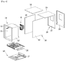
- FIG. 4 is an exploded perspective view of the cabinet according to an embodiment of the present invention
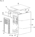
- FIG. 5 is a rear perspective view of the refrigerator according to an embodiment of the present invention
- FIG. 6 is a rear perspective view illustrating some components of the refrigerator according to an embodiment of the present invention.
- the cabinet 10 may include an outer case 100, an inner case 110, and a cabinet cover 190.
- the outer case 100 may include a pair of side panels 102 and 103.
- the pair of side panels 102 and 103 may define an outer appearance of a side surface of the refrigerator 1.
- the outer case 100 may further include a rear panel 160 defining an outer appearance of a rear surface of the refrigerator 1.
- the outer appearance of the refrigerator 1 excluding the door 20 may be defined by the pair of side panels 102 and 103, the cabinet cover 190 and the rear panel 160.
- the cabinet 10 may further include a case supporter 130 supporting the inner case 110 and a base 120 coupled to a lower side of the case supporter 130.
- the cabinet 10 may further include a middle plate 150 defining a foaming space 159 together with the inner case 110.
- the middle plate 150 may cover upper and rear sides of the inner case 110 at a position that is spaced apart from the inner case 110.
- the cabinet 10 may further include a cooling device 50 cooling the storage space 111.
- the case supporter 130 may be disposed between the pair of side panels 102 and 103 in a state where the pair of side panels 102 and 103 are arranged in the horizontal direction.
- the case supporter 130 may be screw-coupled to the pair of side panels 102 and 103 so as to be fixed.
- the base 120 may be disposed below the case supporter 130.
- the base 120 may be disposed between the pair of side panels 102 and 103 and coupled to a lower side of the case supporter 130.
- the base 120 may include a bottom plate 122.
- a front and rear length of the bottom plate 122 may be the same as or similar to that of each of the side panels 102 and 103.
- the bottom plate 122 may define an outer appearance of a bottom surface of the refrigerator 1.
- the base 120 may further include a support rib 127 supporting the rear panel 160.
- the support rib 127 may extend upward from a rear end of the bottom plate 122.
- a handle 126 held by the user may be provided on a rear surface of the support rib 127.
- the handle 126 may be gripped when the user wants to transport the refrigerator 1. As the handle 126 is provided on the support rib 127, the handle 126 is not visible from the outside when the refrigerator 1 is installed.
- the rear surface of the support rib 127 may be disposed on the same plane as the rear end of each of the pair of side panels 102 and 103.
- the handle 126 may protrude backward by a predetermined distance from the rear surface of the support rib 127.
- the handle 126 may include an upper extension portion 126b extending in a horizontal direction from one point of the support rib 127, a front extension portion 126d extending downward from a front end of the upper extension portion 126b, and a pair of side extension portions 126c extending downward from both ends of the upper extension portion 126b.
- a space 126a in which a user's hand is disposed may be defined by each of the extension portions 126b, 126c, and 126d.
- the front extension portion 126d may be disposed to be spaced a predetermined distance from the rear surface of the support rib 127. That is, even when the refrigerator 1 is disposed adjacent to one wall of the installation space, the rear panel 160, the support rib 127, and the display unit 60 to be described later may be spaced apart from the one wall by the front extension portion 126d.
- a flow of air suctioned into the refrigerator 1 by the front extension portion 126d and the opening and closing of the display cover 650 of the display unit 60, which will be described later, may be smoothly performed without interfering with the one wall of the installation space.
- a vertical length of the door 20 is less than that of each of the side panels 102 and 103.
- the top surface of the door 20 may be disposed at the same height as the upper end 102b of each of the side panels 102 and 103.
- the door 20 in the state in which the door 20 closes the storage space 111, the door 20 is disposed higher than the base 120 so that a portion of the base 120 is exposed to the outside.
- the inner case 110 may include a main frame 113 defining the storage space 111 and a front frame 112 extending in a vertical direction from a front edge of the main frame 113.
- the main frame 113 may be formed in a rectangular parallelepiped shape having an opened front surface.
- a front and rear length of the main frame 113 may be less than that of each of the side panels 102 and 103.
- a horizontal width of the main frame 113 may be formed to be less than an interval between the respective side panels 102 and 103.
- the horizontal width of the front frame 112 may be formed to have the same as the interval between the side panels 102 and 103.
- both side surfaces of the main frame 113 are spaced apart from the side panels 102 and 103, respectively.
- the foaming space 159 in which a foaming liquid is filled is defined between both the side surfaces of the main frame 113 and the respective side panels 102 and 103.
- an upper end of the front frame 112 is disposed to be lower than the upper end 102b of each of the side panels 102 and 103.
- a space in which the cabinet cover 190 is disposed is defined above the front frame 112.
- the middle plate 150 may cover the inner case 110 from the rear side of the inner case 110.
- the middle plate 150 may include a rear plate 152 covering a rear surface of the inner case 110 and an upper plate 154 covering a top surface of the inner case 110.
- the upper plate 154 may extend horizontally from an upper end of the rear plate 152.
- the middle plate 150 may be formed in a shape such as " ".
- the upper plate 154 may be seated on an upper end of the front frame 112.
- the upper plate 154 may be attached to a top surface portion of the front frame 112 by an adhesive means.
- the upper plate 154 In a state in which the upper plate 154 is seated on the front frame 112, the upper plate 154 is spaced apart from the top surface of the main frame 113. Thus, the foaming space 159 is defined between the upper plate 154 and the top surface of the main frame 113.
- the rear plate 152 may be installed on the base 120 and the pair of side panels 102 and 103.
- a coupling rib (not shown) extending upward to install the rear plate 152 may be provided on the base 120.
- the coupling rib may be disposed at a relatively rear side rather than the rear surface of the main frame 113.
- a coupling hole (not shown) for coupling of a bolt may be defined in the rear plate 152 and the coupling rib.
- the rear plate 152 may be fixed to the base 120 by being coupled to the coupling rib by the bolt in a state of being in contact with a rear surface of the coupling rib.
- the rear plate 152 may be spaced apart from the rear surface of the main frame 113.
- the foaming space 159 is defined between the rear plate 152 and the rear surface of the main frame 113.
- the rear plate 152 may be installed on the pair of side panels 102 and 103 by a fixing unit 70 (see FIG. 6 ) to be described later.
- the fixing unit 70 may be coupled to a rear side of the rear plate 152, and the fixing unit 70 may be coupled to each of the side panels 102 and 103.
- the fixing unit 70 may be coupled to each of the side panels 102 and 103.
- An injection hole (not shown) for injection of the foaming liquid may be defined in the rear plate 152, and the injection hole may be blocked by a packing (not shown).
- a through-hole 152a through which the cooling device 50 passes may be additionally defined in the rear plate 152.
- a top surface of the upper plate 152 may be disposed lower than the upper end 102b of each of the side panels 102 and 103.
- a space, in which the cabinet cover 190 is disposed, may be defined above the upper plate 152.
- the rear surface of the rear plate 152 is disposed to be spaced inward from the rear end 102c of each of the side panels 102 and 103.
- the rear panel 160 may cover the rear plate 152 from the rear side of the rear plate 152.
- the rear panel 160 may include a panel body 161 that covers the rear surface of the rear plate 152 and a side extension portion 161a that allows a contact area between the pair of side panels 102 and 103 to increase.
- the rear panel 160 may be coupled to the case supporter 130 at the rear side of the rear plate 152 in a state of being spaced apart from the rear plate 152.
- the panel body 161 may be coupled to the case supporter 130.
- the panel body 161 may be disposed above the support rib 127 and coupled to the case supporter 130 by a coupling member such as a screw.
- a coupling hole (not shown) for coupling with the case supporter 130 may be defined in a lower portion of the panel body 161.
- the panel body 161 In the state in which the panel body 161 is coupled to the case supporter 130, the panel body 161 may be disposed between the pair of side panels 102 and 103 while covering the rear side of the rear plate 152.
- a vertical length of the panel body 161 may be less than that of each of the pair of side panels 102 and 103. In a state in which the panel body 161 is coupled to the case supporter 130, the upper end of the panel body 161 is disposed lower than the upper end 102b of each of the side panels 102 and 103.
- a space in which the display unit 60 is disposed is defined above the panel body 161.
- a horizontal width of the panel body 161 may be formed to be the same as the interval between the side panels 102 and 103.
- the rear surface of the panel body 161 may be disposed on the same plane as the rear surface of the display unit 60 and the rear ends 102c of the pair of side panels 102 and 103 so that the outer appearance of the cabinet 10 has the sense of unity.
- the panel body 161 may be disposed on the same plane as the rear surface of the support rib 127.
- the panel body 161 may define the outer appearance of the rear surface of the refrigerator 1 together with the display unit 60 and the support ribs 127.
- the side extension portion 161a may extend vertically from both ends of the panel body 161 to the panel body 161.
- the side extension portion 161a may be formed on at least a portion of both the ends of the panel body 161.
- the side extension portion 161a may be disposed between the pair of side panels 102 and 103.
- the side extension portion 161a In the state in which the side extension portion 161a is disposed between the pair of side panels 102 and 103, the side extension portion 161a may be in contact with the side panels 102 and 103. That is, the side extension portion 161a may be understood as a surface that is in contact with the pair of side panels 102 and 103 when the rear panel 160 is assembled.
- the rear panel 160 may be supported by the pair of side panels 102 and 103 so as to be stably assembled due to the side extension portion 161a.
- the cabinet cover 190 may be detachably coupled to the middle plate 150.
- a cover fixing portion 196 (see FIG. 10 ) for fixing the cabinet cover 190 to the middle plate 150 may be provided on a bottom surface of the cabinet cover 190.
- a cover fixing hole 156 for fixing the cover fixing portion 196 may be provided in the middle plate 150.
- the cover fixing hole 156 may be provided in, for example, the upper plate 154.
- An external air hole (not shown) through which external air is introduced may be defined in the rear panel 160, and the external air hole may be covered by a grill case 510.
- the grill case 510 may be coupled to the rear panel 160 from the rear side of the rear panel 160.
- the grill case 510 may be supported by being seated on the top surface of the handle 126.
- the grill case 510 may have a polygonal shape by bending a plate.
- the grill case 510 has a first surface spaced apart from the rear panel 160 and parallel to the rear panel 160, a second surface extending from an upper end of the first surface toward the rear panel 160, and a pair of third surfaces extending from side ends of the first surface toward the rear panel 160.
- the third surface may extend from each of the side ends of the first surface so as to be inclined outward toward the rear panel 160. That is, the pair of third surfaces may move away from each other as the pair of third surfaces are closer to the rear panel 160.
- a first external air suction hole 512 and a second external air suction hole 514 may be defined in the grill case 510.
- the first external air suction hole 512 may be defined by a grill formed on the first surface.
- the second external air intake hole 514 may be defined by a grill formed on the third surface.
- external air may be introduced into the refrigerator 1 through the first external air suction hole 512 and the second external air suction hole 514.
- the external air may be smoothly suctioned through the second external air suction hole 514.
- a display unit 60 may be installed at a rear side of an upper end of the cabinet 10.
- the display unit 60 may be disposed at a rear side of the cabinet cover 190.
- a portion of the display unit 60 may be covered by a display cover 650.
- the display cover 650 may cover the display panel 605 of the display unit 60.
- the display cover 650 covers the display panel 605, it is possible to prevent other components of the display unit 60 from being exposed to the outside. For example, the external exposure of the display panel 605 is prevented by the display cover 650.
- the display cover 650 together with the cabinet cover 190 defines the top surface of the refrigerator 1. That is, in the state in which the display cover 650 covers the display panel 605, the top surface of the display cover 650 may be disposed at the same height as the top surface of the cabinet cover 190.
- the top surfaces of the display cover 650 and the cabinet cover 190 may define a continuous surface. According to the present invention, since the external exposure of the configuration of the display unit 60 is prevented, the outer appearance of the refrigerator 1 is improved to be neat.
- the display unit 60 Since the display unit 60 is disposed above the cabinet 10, even if the height of the refrigerator 1 is low, the user may easily see the display panel 605 in the state in which the display cover 650 rotates.
- the display cover 650 covers the display panel 605, even if water or liquid falls on the top surface of the refrigerator 1, the water or liquid may be prevented from flowing into the display unit 60.
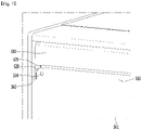
- FIG. 7 is an enlarged view illustrating a portion A of FIG. 5
- FIG. 8 is a view illustrating a state in which the display unit is assembled with the fixing unit in a state in which the rear panel is removed according to an embodiment of the present invention
- FIG. 9 is an enlarged view of a portion B of FIG. 8
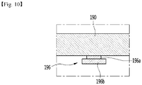
- FIG. 10 is a cross-sectional view of the cover fixing portion provided on the cabinet cover according to an embodiment of the present invention
- FIG. 11 is an enlarged view illustrating some components of the middle plate according to an embodiment of the present invention.
- the rear panel 160 may be coupled to the display unit 60.
- the display unit 60 may be provided with a panel seating portion 628 on which the rear panel 160 is seated.
- the panel seating portion 628 may be formed on a rear surface of a display case 610 to be described later.
- the rear panel 160 may further include a panel extension portion 163 extending to be coupled with the display unit 60.
- the panel extension portion 163 may extend upward from an upper end of the rear panel 160.
- the panel extension portion 163 may be formed to extend upward from at least a portion of an upper end 162 (see FIG. 7 ) of the rear panel 160.
- a vertical extension length of the panel extension portion 163 may correspond to a vertical length of the panel seating portion 628. In a state in which the panel extension portion 163 is seated on the panel seating portion 628, an upper end of the panel extension portion 163 may be disposed lower than a lower end of the rear surface portion 623 (see FIG. 13 ) of the display unit 60 to be described later.
- a panel seating protrusion 629 which will be described later, may be seated on the upper end of the panel extension portion 163.
- Both ends of the panel extension portion 163 may correspond to the shape of the panel seating portion 628.
- each of both the ends of the panel extension portion 163 may be rounded to correspond to the shape of the panel seating portion 628.
- Each of both the ends of the panel extension portion 163 may be rounded upward from the upper end 162 of the panel body 161.
- the rear panel 160 may be coupled to the display unit 60.
- the rear panel 160 may be coupled to the display unit 60 by, for example, a third volt S3.
- a first bolt coupling hole 164 to which the third bolt S3 is coupled may be defined in each of both the ends of the panel extension portion 163.
- the first bolt coupling hole 164 may be aligned with a second bolt coupling hole 626a (see FIG. 13 ) defined in the display case to be described later in the front and rear direction.
- the rear panel 160 may further include a support portion 163a extending from the panel extension portion 163.
- the support portion 163a may extend from the panel extension portion 163 and be supported by a support rib 625 of the display case 610, which will be described later.
- the support portion 163a may be bent from an upper end of the panel extension portion 163 so as to be in contact with the support rib 625.
- the rear panel 160 and the display unit 60 may be stably coupled by the support portion 163a.
- the support portion 163a may extend horizontally from the upper end of the panel extension portion 163. In this case, the support portion 163a may be in line contact with the support rib 626 of the display case 610.
- the support portion 163a may be bent to extend in a " " shape from the upper end of the panel extension portion 163. In this case, the support portion 163a may be in surface contact with the support rib 626 of the display case 610.
- the refrigerator 1 may further include a fixing unit 70.
- the middle plate 150 and the side panels 102 and 103 may be connected to each other by the fixing unit 70.
- the fixing unit 70 may be bent in an approximately " " shape.
- the first bolt S1 may pass through a portion of the fixing unit 70 and be coupled to the side panels 102 and 103
- the second bolt S2 may pass through the other portion of the fixing unit 70 and be coupled to the middle plate 150.
- the fixing unit 70 may be coupled to the rear plate 152 and each of the side panels 102 and 103 from the rear side of the rear plate 152. Thus, not only the rear plate 152 is fixed to the side panels 102 and 103 by the fixing unit 70, but also deformation of the rear plate 152 during a process of filling the foaming liquid may be prevented.
- the display unit 60 may be mounted on the refrigerator 1 by the fixing unit 70.
- the fixing protrusion 730 may be provided on the fixing unit 70 so that the fixing protrusion 730 is inserted into the protrusion accommodation portion 615 of the display unit 60.
- the display unit 60 When the display unit 60 is assembled with the fixing protrusion 730 so that the fixing protrusion 730 is inserted into the protrusion accommodation portion 615 of the display unit 60, the display unit 60 may be disposed above the fixing unit 70.
- the position of the display unit 60 may be fixed.
- the display unit 60 may be separated from the fixing protrusion 730 of the fixing unit 70 to easily release the coupling in position of the display unit 60.
- a detailed description with respect to disassembly of the display unit 60 and the fixing protrusion 730 will be described later.
- the refrigerator according to this embodiment may further include a module mounting case 810 for mounting a wireless charging module capable of wirelessly charging a battery of a mobile device and a cutoff portion 151 for mounting the module mounting case 810.
- the module mounting case 810 may be coupled to the middle plate 150, for example, by a screw.
- the cutoff portion 151 may be disposed at an upper corner portion of the middle plate 150.
- the module mounting case 810 may be disposed on the upper rear portion of the refrigerator 1 by the position of the cutoff portion 151.
- the wireless charging module may be covered by the cabinet cover 190.
- the module mounting case 810 may be formed so that the rear is opened.
- the wireless charging module may be mounted or detached through the rear opening.
- the module mounting case 810 may be mounted on the middle plate 150 by the cutoff portion 151 to adhere to an inner surface of the middle plate 150.
- module mounting case 810 may be screw-coupled to the middle plate 150 in the state of being seated on the middle plate 150.
- the cabinet cover 190 may be detachably coupled to the middle plate 150.
- the cabinet cover 190 may be attached to and detached from the middle plate 150.
- the cover fixing portion 196 may be provided on a bottom surface of the cabinet cover 190.
- the cover fixing portion 196 may be attached to the bottom surface of the cabinet cover 190 by an adhesive means.
- the adhesive means may include an adhesive or a double-sided tape, and it is noted that there is no limitation in types of the adhesive means in the present invention.
- the cover fixing portion 196 may be fixed to the bottom surface of the cabinet cover 190 by a screw.
- a plurality of cover fixing portions 196 may be provided.
- the plurality of cover fixing portions 196 may be arranged to be spaced apart from each other in the horizontal direction of the cabinet cover 190 and may be arranged to be spaced apart from each other in the front and rear direction.
- each of the cover fixing portions 196 may include a first portion 196a and a second portion 196b having a diameter or a size greater than that of the first portion 196a.
- the first portion 196a is disposed between the cabinet cover 190 and the second portion 196b, and the first portion 196a is in contact with a bottom surface of the cabinet cover 190.
- the cover fixing hole 156 may be defined in the upper plate 154.
- the cabinet cover 190 may be coupled to the upper plate 154 by the cover fixing hole 156 and the cover fixing portion 196 of the cabinet cover 190.
- the cabinet cover 190 may be mounted on the upper plate 154 to be fixed in position and simultaneously may cover the upper side of the upper plate 154.
- a plurality of cover fixing holes 156 may be defined. Some of the plurality of cover fixing holes 156 may be defined to be adjacent to the cutoff portion 151.
- some of the plurality of cover fixing holes 156 may be disposed to be adjacent to the cutoff portion 151. That is, some of the plurality of cover fixing holes 156 may be disposed to be adjacent to the module mounting case 810.
- the cover fixing hole 156 may include a first hole 156a having a size equal to or greater than that of the second portion 196b of the cover fixing portion 196 and a second hole 156b extending from the first hole 156a and having a size less than that of the first hole 156a.
- the second hole 156b may be defined to be less than the second portion 196b of the cover fixing portion 196.
- the second hole 156b may have a size that is equal to or greater than that of the first portion 196a of the cover fixing portion 196.
- the second portion 196b of the cover fixing portion 196 and the first hole 156a of the cover fixing hole 156 are aligned with each other.
- the second portion 196b of the cover fixing portion 196 passes through the first hole 156a of the cover fixing hole 156.
- the first portion 196a of the cover fixing portion 196 is disposed within the first hole 156a, and the cabinet cover 190 is seated on the upper plate 154.
- the cabinet cover 190 horizontally moves so that the first portion 196a of the cover fixing portion 196 is disposed in the second hole 156b of the cover fixing hole 156.
- the cabinet cover 190 may move backward.
- the second portion 196b of the cover fixing portion 196 is in contact with a bottom surface 154 of the upper portion 154.
- the separation of the cabinet cover 190 from the middle plate 150 may be prevented unless the cabinet cover 190 is pushed backward.
- the rear surface 190b of the cabinet cover 190 may be in contact with a front surface 611 (see FIG. 12 ) of the display case 610 of the display unit 60 to be described later.
- the top surface of the cabinet cover 190 and the display unit 60 may be disposed to have a sense of unity.
- the cabinet cover 190 since the cabinet cover 190 is coupled to the middle plate 150 in a sliding manner, the cabinet cover 190 may be easily coupled to the middle plate 150 and easily separated from the middle plate 150.
- the cabinet cover 190 is capable of being replaced. That is, since the cabinet cover 190 having a design or color desired by the user is coupled to the middle plate 150, there is an advantage that the design of the outer appearance of the refrigerator 1 may be diversified.
- the cabinet cover 190 when the cabinet cover 190 is damaged, there is an advantage that the cabinet cover 190 is capable of being replaced.
- the user uses the refrigerator 1 as the side table refrigerator, the user may be easily accessible to the cabinet cover 190 and uses the refrigerator 1 for the purpose of the side table, and thus, there is a high risk of damage or the like.
- the rear surface 190b of the cabinet cover 190 may be disposed inside the rear end 102c of each of the side panels 102 and 103.
- the fixing unit 70 may be disposed lower than the module mounting case 810 and the cutoff portion 151 in a state of being coupled to the rear side of the rear plate 152. Therefore, when the module mounting case 810 is mounted or separated, an interference due to the fixing unit 70 may be prevented.
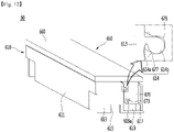
- FIG. 12 is a perspective view of the refrigerator according to an embodiment of the present invention
- FIG. 13 is a view illustrating a state in which the display cover of FIG. 12 rotates
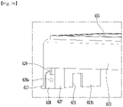
- FIG. 14 is a perspective view of the display case according to an embodiment of the present invention
- FIG. 15 is a perspective view of the fixing unit according to an embodiment of the present invention.
- the refrigerator 1 may further include the display unit 60 and the fixing unit 70 for assembling the display unit 60.
- the display unit 60 may include a display case 610, a display PCB (not shown) accommodated in the display case 610, a display panel 605 that covers an upper side of the display PCB, and a display cover 650 that covers an upper side of the display panel 605.
- the display panel 605 may be coupled to the upper side of the display case 610. Light irradiated from one or more light emitting portions installed in the display PCB may pass through the display panel 605.
- the display case 610 may be seated between, for example, the side panels 102 and 103. As the display case 610 and the fixing unit 70 are assembled, the display case 610 may be installed between the side panels 102 and 103.
- a protrusion accommodation portion 615 to be described later may be defined in the display case 610, and the fixing protrusion 730 of the fixing unit 70 may be inserted into the protrusion accommodation portion 615 so that the display case 610 and the fixing unit 70 are assembled.
- the display unit 60 may be disposed at the rear side of the cabinet cover 190.
- the display cover 650 may be rotatably coupled to the display case 610. As another example, the display cover 650 may be rotatably coupled to one component of the cabinet 10.
- the display cover 650 may cover the display panel 605 in a state of being coupled to each of the side panels 102 and 103.
- the display cover 650 may include a cover plate 660 for covering the top surface of the display panel 605 and a pair of extension portions 670 extending from both ends of the cover plate 660.
- the pair of extension portions 670 may be coupled to both surfaces of the display case 610. In the state in which the pair of extension portions 670 are coupled to the display case 610, a seating groove 619 for seating each of the extension portions 670 may be defined in each of both sides of the display case 610 so that the pair of extension portions 670 do not protrude outward.
- each of the extension portions 670 may be disposed between a portion of the display case 610 and each of the side panels 102 and 103.
- the seating groove 619 may be disposed at a rear side of the protrusion accommodation portion 615. That is, each of the extension portions 670 seated in the seating groove 619 may be prevented from interfering with the protrusion accommodation portion 615 and the fixing protrusion 730 accommodated in the protrusion accommodation portion 615 during the rotation.
- a hinge shafts 619a for providing a center of rotation of the display cover 650 may be provided on each of both surfaces of the display case 610.
- the hinge shaft 619a may protrude from the display case 610 to both sides.
- the hinge shaft 619a may be formed in the seating groove 619.
- the hinge shaft 619a may be formed to protrude from an outer surface of the seating groove 619.
- a shaft hole 673 through which the hinge shaft 619a passes may be defined in each of the extension portions 670.
- the display cover 650 may rotate around the hinge shaft 619a.
- the display cover 650 may rotate within a range between a first position, at which the display panel 605 is covered, and a second position at which the display panel 605 is exposed to the outside.
- a rotation preventing protrusion 614 may be formed on one of the display case 610 and the display cover 650, and a protrusion groove 676, in which the rotation preventing protrusion 614 may be accommodated in the other one so that the display cover 650 is fixed in position.
- FIG. 12 a structure, in which the rotation preventing protrusion 614 is formed on the display case 610, and the protrusion groove 676 is formed on the extension portion 670 of the display cover 650, is illustrated.
- the rotation preventing protrusion 614 may include a neck portion 614a and an insertion portion 614b having a width greater than that of the neck portion 614a.
- the insertion portion 614b may be rounded to be accommodated in the protrusion groove 676 during the rotation of the display cover 650.
- the insertion portion 614b may be formed in a substantially circular shape.
- a radius of the insertion portion 614b may be equal to or greater than a width of the neck portion 614a.
- a hook protrusion 677 may be formed in the protrusion groove 676 so as to be hooked to the insertion portion 614b in a state in which the insertion portion 614b is inserted.
- the display cover 650 may not rotate. That is, it is possible to prevent the display cover 650 from unintentionally rotating from the first position to the second position.
- the cover plate 660 may be spaced a predetermined distance from the rear surface of the display case 610. In detail, at the second position, the cover plate 660 may be spaced a predetermined distance from a panel seating protrusion 629 (see FIG. 14 ) to be described later.
- the cover plate 660 may be spaced a predetermined distance from the top surface of the display panel 605.
- An extension length d1 of the extension portion 670 may be less than a vertical length of the display case 610.
- the extension length d1 of the extension portion 670 may be less than a vertical length of the seating groove 619.
- a lower end of the extension portion 670 is disposed higher than a lower end of the seating groove 619.
- a front and rear width d3 of the extension portion 670 is less than a distance from a time at which the seating groove 619 is formed, to the rear surface (rear portion 623 to be described later) of the display case 610.
- the rear end of the extension portion 670 may be disposed in front of a rear surface (a rear portion 623 to be described later) of the display case 610.
- the display case 610 may include a front portion 611 disposed at a front side, a pair of side surface portions 613 formed at left and right sides, a support portion 617 extending backward from each of the side surface portions 613, and a rear portion 623 extending downward from a rear end of the display panel 605.
- the front potion 611 may be disposed at the rear side of the cabinet cover 190 in a state in which the display unit 60 is assembled to the fixing unit 70. At least a portion of the front portion 611 may be in contact with the rear surface 190b of the cabinet cover 190.
- the front potion 611 may be disposed on the same plane as the front surface of the cover plate 660.
- the pair of side surface portions 613 may be disposed to face the side panels 102 and 103, respectively.
- An outer surface of each of the side surface portions 613 may be disposed closer to each of the side panels 102 and 103 than the outer surface of the seating groove 619 and the outer surface of the extension portion 670.
- the side surface portions 613 may be in contact with the side panels 102 and 103, respectively.
- the outer surface of the extension portion 670 may be disposed inside the outer surface of the side surface portion 613. That is, the outer surface of the extension portion 670 may be disposed farther from each of the side panels 102 and 103 than the outer surface of the side surface portion 613.
- the extension portion 670 is prevented from causing friction with the pair of side panels 102 and 103 to smoothly rotate.
- the support portion 617 may be disposed below the seating groove 619.
- the support portion 617 may extend from the side surface portion 613 toward the rear surface of the display case 610.
- the seating groove 619 may be recessed downward from the upper end of the display case 610 to the support 617 and may extend from the rear end of the side surface portion 613 to the rear surface of the display case 610.
- a lower end of the extension portion 670 may be spaced apart from the support portion 617.
- the rear end of the extension portion 670 may be supported by the support portion 617 and be prevented from excessively rotating.
- the support portion 617 may be disposed on the same plane as the side surface portion 613. Thus, when the display case 610 is mounted on the fixing unit 70, the support portion 617 is supported by the pair of side panels 102 and 103 together with the side surface portion 613, and thus, the display unit 60 may be installed stably.
- the rotation of the display cover 650 may be stably performed without distortion.
- a front and rear length d2 of the support portion 617 may be less than the extension length d1 of the extension portion 670 and greater than the front and rear width d3 of the extension portion 670.
- the cover plate 660 and the extension portion 670 may be stably supported at the second position without the cover plate 660 interferes with the support portion 617.
- the display case 610 may further include a protrusion accommodation portion 615 into which the fixing protrusion 730 of the fixing unit 70 is inserted.
- the protrusion accommodation portion 615 may be formed in the side surface portion 613.
- the protrusion accommodation portion 615 may be formed to extend upward from the lower end of the side surface portion 613.
- the protrusion accommodation portion 615 may be understood to have a shape of a groove that is recessed upward from the lower end of the side surface portion 613.
- An upper end of the protrusion accommodation portion 615 may be formed to be lower than the height of each of the hinge shaft 619a and the shaft hole 673.
- the protrusion accommodation portion 615 may be formed to correspond to the shape of the fixing protrusion 730.
- the protrusion accommodation portion 615 and the fixing protrusion 730 may be formed, for example, in a polygonal shape. In the drawings, for example, it is illustrated that each of the protrusion accommodation portion 615 and the fixing protrusion 730 is formed in a rectangular shape.
- the display case 610 may further include a horizontal portion 621 horizontally extending backward from the rear end of the display panel 605.
- a top surface of the horizontal portion 621 may be disposed lower than the top surface of the display panel 605.
- the rear portion 623 may extend downward from a rear end of the horizontal portion 621.
- An extension length of the rear portion 623 may be less than a vertical length of each of the front potion 611 and the side surface portion 613.
- a lower end of the rear portion 623 is disposed higher than the lower end of each of the front portion 611 and the side surface portion 613.
- a lower end of the rear portion 623 may be formed to be higher than the top surface of the support portion 617.
- a connection portion between the horizontal portion 621 and the rear portion 623 may be formed to be round.
- the rotation of the cover plate 660 may be guided by the rounded shape.
- a rear surface of the rear portion 623 may be defined as a rear surface of each of the display unit 60 and the display case 610.
- the rear surface of the support portion 617 may be disposed on the same plane as the rear surface of the rear portion 623. Thus, when the rear panel 160 is seated on the panel seating portion 628, the rear surface of the support portion 617, the rear portion 623, and the rear panel 160 form a sense of unity.
- an outer surface of the seating groove 619 may be disposed on the same plane as a side surface of the rear portion 623.
- a panel seating portion 628 for seating the rear panel 160 may be formed on the rear surface of the display unit 60.
- the panel seating portion 628 may be formed by being recessed forward from the rear surface of the display unit 60.
- the panel seating portion 628 may be disposed below the rear portion 623.
- the panel seating portion 628 may be disposed below both ends of the rear portion 623.
- the display case 610 may further include a pair of protrusions 627 extending downward from both the ends of the rear portion 623.
- the pair of protrusions 627 may extend inward from the support portion 617 and the seating groove 619.
- a thickness of the protrusion 627 may be greater than that of the side surface portion 613. That is, an inner surface of the protrusion 627 may be disposed on the inside rather than the inner surface 613b of the side surface portion 613 and may be disposed further away from each of the side panels 102 and 103.
- An area on which the panel extension portion 163 of the rear panel 160 is seated may increase due to the thickness of the protrusion 627, and thus, the rear panel 160 may be stably seated.
- the rear surface of the protrusion 627 may be disposed on the same plane as the rear surface of the rear portion 623 and the rear surface of the support portion 617.
- the panel seating portion 628 may be formed to be recessed forward from the rear surface of the protrusion 627.
- the "front side” may be understood as a direction toward the front potion 611 or a direction toward the storage space 111 and the door 20.
- a recessed depth of the panel seating portion 628 may be the same as the thickness of the panel body 161 of the rear panel 160. That is, when the rear panel 160 is seated on the panel seating portion 628, the rear panel 160, the rear surface of the protrusion 627, and the rear surface of the rear surface portion 623 may form a sense of unity.
- the shape of the panel seating portion 628 may be formed to correspond to the shape of each of both ends of the panel extension portion 163.
- a portion of the panel seating portion 628 may be formed to be rounded with a predetermined curvature.
- each of both the ends of the panel extension portion 163 may be the same as that of a portion of the panel seating portion 628.
- the display case 610 may further include a panel mounting protrusion 629 for mounting with the rear panel 160.
- the panel seating protrusion 629 may be disposed below the rear portion 623.
- the panel seating protrusion 629 may be disposed above the panel seating portion 628. In the state in which the panel extension portion 163 of the rear panel 160 is seated on the panel seating portion 628, the panel seating protrusion 629 may be seated on the upper end of the panel extension portion 163.
- the rear panel 160 may be seated on the panel seat portion 628, and the panel seat protrusion 629 of the display case 610 may be seated on the rear panel 160, and thus, the display unit 60 and the rear panel 160 may be firmly coupled to each other.
- a second bolt coupling hole 628a through which the third bolt S3 is coupled may be defined in the display case 610 for coupling with the rear panel 160.
- the second bolt coupling hole 628a may be defined in the panel seating portion 628.
- the second bolt coupling hole 628a may be aligned with the first bolt coupling hole 164 of the panel extension portion 163 in the state in which the rear panel 160 is seated on the panel accommodation portion 628.
- the third bolt S3 may be coupled by sequentially passing through the first bolt coupling hole 164 and the second bolt coupling hole 628a.
- the display case 610 may further include a support rib 625 for supporting the rear panel 160.
- the support rib 625 may extend downward from a lower end of the rear portion 623.
- the support rib 625 may be defined as a "panel support rib”.
- a horizontal length of the support rib 625 may be less than that of the rear portion 623.
- the support rib 625 may be disposed between the pair of protrusions 627.
- a thickness of the support rib 625 may be less than that of the rear portion 623.
- a rear surface of the support rib 625 may be disposed on the same plane as the panel seating portion 628.
- the other portion of the panel extension portion 163 may be seated on the support rib 625.
- the rear surface of the support rib 625 may be disposed in front of the panel seating portion 628.
- the support portion 163a of the rear panel 160 may be seated on the support rib 625.
- the rear panel 160 since the area on which the rear panel 160 is seated increases by the support rib 625, the rear panel 160 may be stably seated.
- the fixing unit 70 may include a fixing protrusion 730 for fixing with the display case 610.
- the fixing protrusion 730 is accommodated in the protrusion accommodation portion 615 of the display case 610, the display unit 60 may be detachably fixed to the fixing unit 70.
- the fixing unit 70 may include a first body 710 disposed to face the side panels 102 and 103.
- the fixing unit 70 may include a second body 720 disposed to face the middle plate 150.
- the second body 720 may be bent from the first body 710.
- the fixing unit 70 may be formed in an approximately “ “” shape.
- the first body 710 and the second body 720 may be connected to cross each other. It should be noted that the first body 710 and the second body 720 are integrally formed.
- first body 710 and the second body 720 may be disposed to be perpendicular to each other.
- One of the first body 710 and the second body 720 may be coupled to the middle plate 150, and the other may be coupled to the side panels 102 and 103.
- the first body 710 may be coupled to the side panels 102 and 103, and the second body 720 may be coupled to the rear plate 152 of the middle plate 150.
- the first body 710 may be coupled to the side panels 102 and 103.
- the fixing unit 70 may be fixed to the cabinet 10 by the first body 710.
- the second body 720 may be coupled to the middle plate 150.
- the fixing unit 70 may be fixed to the cabinet 10 by the second body 720.
- the fixing protrusion 730 may be provided on the first body 710.
- the fixing protrusion 730 may extend upward or downward from an upper end or lower end of the first body 710.
- the fixing protrusion 730 may be provided on any one of an upper end and a lower end of the first body 710.
- the fixing protrusion 730 may be provided on both the upper end and the lower end of the first body 710.
- the fixing protrusions 730 provided at the upper end and lower end of the first body 710 may be formed in the same manner.
- the fixing protrusion 730 may be inserted into the protrusion accommodation portion 615 of the display case 610 by the fixing protrusions 730, which are provided in plurality.
- the fixing unit 60 provides the plurality of fixing protrusions 730, since the fixing unit 60 performs the same role at both the left and right sides of the refrigerator 1, a common use of the fixed unit 60 may be possible.
- An area of the first body 710 may be greater than that of the second body 720. Since the area on which the display case 610 is seated on the fixing unit 60 increases due to the relatively large area of the first body 710, the stable coupling may be possible.
- the fixing protrusion 730 may be formed at a position that is insertable into the protrusion accommodation portion 615 of the display case 610 among the upper ends of the first body 710.
- a distance from the front end of the side surface portion 613 to the protrusion accommodation portion 615 may be the same as a distance from the second body 720 to the fixing protrusion 730.
- the lower end of the side surface portion 613 of the display case 610 may be seated on the upper end of the first body 710 and may be supported by the fixing unit 60.
- the fixing protrusion 730 may be provided on the second body 720.
- the position of the protrusion accommodation portion 615 in the display case 610 may be changed to a position into which the fixing protrusion 730 of the second body 720 is inserted.
- a thickness of each of the first body 710 and the fixing protrusion 730 may be formed to be thicker than the thickness of the side surface portion 613. That is, the display case 610 may be stably seated and supported on the fixing unit 60 due to the thickness difference.
- a protrusion height of the fixing protrusion 730 may be formed to be the same as the height of the protrusion accommodation portion 615.
- a bottom surface of the side surface portion 613 may be seated on the top surface of the first body 710 on which the fixing protrusion 730 is formed.
- Bolt coupling holes 717 and 727 for the coupling of the first bolt S1 and the second bolt S2 may be formed in the first body 710 and the second body 720.
- the first bolt S1 may pass through the bolt coupling hole 717 of the first body 710 so as to be coupled to the side panels 102 and 103.
- the bolt coupling hole 717 of the first body 710 may be disposed between the fixing protrusions 730.
- the display case 610 may be more stably seated according to coupling force of the first bolt S1.
- the second bolt S2 may pass through the bolt coupling hole 727 of the second body 720 so as to be coupled to the middle plate 150.
- the bolt coupling hole 727 of the second body 720 may be formed adjacent to the first body 710.
- the bolt coupling hole 727 of the second body 720 may be formed at a point at which the first body 710 and the second body 720 are in contact with each other.
- FIG. 16 is an enlarged view illustrating a portion C of FIG. 14
- FIG. 17 is a view illustrating a state in which the display unit and the fixing unit are separated from each other according to an embodiment of the present invention.
- FIG. 16 illustrates a portion B of FIG. 14 in a direction from the support rib 625 to the inner surface 613a of the side surface portion 613.
- the protrusion accommodation portion 615 may extend in a vertical direction.
- the protrusion accommodation portion 615 may be formed vertically.
- the protrusion accommodation portion 615 may be formed to be perpendicular to the display panel 605 or the cabinet cover 190.
- the fixing protrusion 730 may be formed vertically to correspond to the protrusion accommodation portion 615.
- the fixing protrusion 730 may be formed to be perpendicular to a direction in which the first body 710 extends from the second body 720.
- the display case 610 may be assembled in a direction that is perpendicular to the fixing unit 70 and may be separated from the fixing unit 70 in the vertical direction.
- FIG. 18 is a view illustrating a process of separating the display unit from the cabinet according to an embodiment of the present invention
- FIG. 19 is a side view illustrating a state in which the display unit is separated
- FIG. 20 is a view illustrating a state in which the cabinet cover is separated backward according to an embodiment of the present invention.
- the third bolt S3 coupling the rear panel 160 to the display case 610 may be separated.
- the rear panel 160 may be disposed between the pair of side panels 102 and 103 by the screw-coupling with the case supporter 130 or the like.
- the display unit 60 may be separated from the fixing unit 70.
- the mounting position may be maintained by inserting the fixing protrusion 730 into the protrusion accommodation portion 615. That is, the upward movement of the display unit 60 may not be limited except for the third bolt S3.
- the display unit 60 may move upward to release the insertion of the fixing protrusion 730 from the protrusion accommodation portion 615, and thus, the display unit 60 may be removed.
- the display unit 60 Since there is no coupling structure such as a screw between the display unit 60 and the pair of side panels 102 and 103 or between the display unit 60 and the fixing unit 70, the display unit 60 may be separated from the refrigerator only by lifting the display unit 60 upward.
- the display unit 60 may be separated simply and quickly.
- the cabinet cover 190 may be detached from the middle plate 150.
- the cabinet cover 190 may move backward to separate the cabinet cover 190 from the middle plate 150.
- the cabinet cover 190 may be separated by allow the cabinet cover 190 to move so as to release the coupling with the middle plate 150.
- the cover fixing portion 196 of the cabinet cover 190 may be separated from the cover fixing hole 156 of the middle plate 150.
- the cabinet cover 190 may move (f2) to the refrigerator 1 by allowing the cabinet cover 190 to move upward.
- the display unit 60 may move upward, and the backward and upward movements of the cabinet cover 190 may be sequentially performed to separate the cabinet cover 190 from the refrigerator 1 in a short time.
- the cabinet cover 190 is disassembled by the release of the coupling of the bolt S3, the upward movement of the display unit 60, and the disassembly of the cabinet cover 190, the process of disassembling the cabinet cover 190 may be minimized.
- the user's desire to replace the cabinet cover 190 may increase, and the user's desire to replace the new design cabinet cover 190 may be easily satisfy.
- the display unit 60 may be easily assembled in the refrigerator 1.
- the display unit 60 is assembled to the upper side of the fixing unit 70, and then, the third bold S3 is coupled, since the mounting of the display unit 60 may be completed, there may be an advantage in that the assembly process is simple.
- the display unit 60 may be reassembled in a short time after the cabinet cover 190 is replaced by the simple assembly process of the display unit 60.
- the display unit 60 may be stably mounted on the refrigerator 1 without moving forward, backward, or upward.
- the fixing protrusion 730 may be mounted in the protrusion accommodation portion 615 to prevent the front and rear movement of the display unit 60, and the third bolt S3 may be coupled to prevent the display unit 60 from moving upward.
Landscapes
- Engineering & Computer Science (AREA)
- Chemical & Material Sciences (AREA)
- Combustion & Propulsion (AREA)
- Physics & Mathematics (AREA)
- Mechanical Engineering (AREA)
- Thermal Sciences (AREA)
- General Engineering & Computer Science (AREA)
- Refrigerator Housings (AREA)
- Devices That Are Associated With Refrigeration Equipment (AREA)
Abstract
Description
- The present invention relates to a refrigerator.
- Generally, refrigerators are household appliances that are capable of store objects such as foods at a low temperature in a storage space provided in a cabinet. Since the storage space is surrounded by heat insulation wall, the inside of the storage space may be maintained at a temperature less than an external temperature.
- The storage space may be classified into a refrigerating compartment or a freezing compartment according to a temperature range of the storage space. The food may be stored in the refrigerating compartment or the freezing compartment according to the type or condition of the food.
- The refrigerator may be provided as a built-in type together with other electronic devices in the kitchen. In this case, a design in outer appearance of the refrigerator is performed in harmony with the furniture in the kitchen.
- In addition, in recent years, installation positions of the refrigerator have been diversified, such as placing the refrigerator in the living room or the room instead of the kitchen according to various needs of the user.
- As the installation positions of the refrigerator are diversified, the design of the outer appearance of the refrigerator is performed so that the outer appearance of the refrigerator is harmonized with the furniture in a space in which the refrigerator is installed.
- For example, the outer appearance of the refrigerator may be designed to be made of wood to be harmonized with the furniture made of wood.
- A refrigerator, in which a furniture door and a refrigerator door, which are made of wood, are screw-coupled to each other, is disclosed in
Korean Patent Publication No. 10-2004-0003319 - However, the outer appearance made of the wood material may be damaged by moisture or the like when used for a long period of time and may require service such as replacement.
- However, in the case of the prior art document, if it is required to perform a service such as the replacement or repair of the damaged furniture door, all the coupled screws have to be released, and thus, there is a problem in which a time taken for the service is long.
- In addition, when a main body needs to be removed because the service of inner components is required, it takes a long time to disassemble the screw-coupled body, and thus, there is a problem in that it is difficult to be accessed to the inner components.
- An object of the present invention is to provide a refrigerator in which a cabinet cover made of a wood material is easily disassembled.
- In addition, an object of the present invention is to provide a refrigerator in which a cabinet cover is easily disassembled without disassembling a rear panel disposed at a rear side from a cabinet.
- In addition, an object of the present invention is to provide a refrigerator in which a display unit disposed at a rear side of a cabinet cover is easily separated from a cabinet.
- In addition, an object of the present invention is to provide a refrigerator in which a time required for replacing and reassembling a cabinet cover is saved.
- A refrigerator according to the present invention for achieving the above objects includes: a cabinet provided with a storage space and including a pair of side panels configured to define an outer appearance of a side surface; a cabinet cover disposed between the pair of side panels and configured to define an outer appearance of a top surface; a display unit disposed behind the cabinet cover and provided for user's manipulation; and a fixing unit which is fixed to the cabinet and disposed between the pair of side panels and to which the display unit is separably fixed, wherein the display unit is installed to be separated upward from the fixing unit. Therefore, there may be an advantage in that it is easy to separate the display unit from the cabinet.
- The cabinet cover may be detached backward in a state of being separated from the display unit. Therefore, as the display unit is easily separated, the cabinet cover may be easily and quickly separated from the cabinet.
- The fixing unit may include a fixing protrusion, and a protrusion accommodation portion, in which the fixing protrusion is accommodated, may be provided in the display unit.
- The fixing unit may further include a first body disposed to face the side panels, and the fixing protrusion protrudes from the first body.
- The refrigerator may further include: an inner case configured to define the storage space; and
a middle plate configured to cover an outer circumference of the inner case, wherein the fixing unit may further include a second body bent from the first body to face the middle plate. - The first body may be coupled to the side panels, and the second body may be coupled to the middle plate. Therefore, the fixing unit may facilitate the separation of the display unit and firmly couple the side panel and the middle plate to each other.
- The first body may be coupled to the side panels, or the second body may be coupled to the middle plate.
- The middle plate may include a rear plate disposed between the inner case and the rear panel, and the second body may be coupled to the rear plate.
- The fixing protrusion may be provided in plurality, and the plurality of fixing protrusions may protrude from top and bottom surfaces of the first body.
- The cabinet may further include: an inner case configured to define the storage space; and a middle plate configured to cover an outer circumference of the inner case, the fixing unit may include: a first body disposed to face the side panels; and a second body bent from the first body to face the middle plate, and the fixing protrusion may protrude from the second body.
- The refrigerator may further include a rear panel configured to constitute the cabinet and define an outer appearance of a rear surface, wherein the display unit may further include a panel seating portion seated on the rear panel.
- A bolt coupling hole through which a bolt is coupled to restrict vertical movement of the display unit may be defined in each of the panel seating portion and the rear panel.
- The display unit may include: a display case above which a display panel is provided; and a display cover configured to cover the display panel and rotatably coupled to the display case, wherein the protrusion accommodation portion may be disposed on a side surface portion of the display case.
- The protrusion accommodation portion may be recessed upward from a bottom surface of the side surface portion.
- The fixing protrusion may have a thickness greater than that of the side surface portion.
- The fixing protrusion may have the same height as the protrusion accommodation portion so that a bottom surface of the side surface portion is seated on a top surface of the first body.
- A seating groove recessed downward from an upper end of the side surface portion may be defined in the display case, the display cover may include: a cover plate configured to cover an upper side of the display panel; and a pair of extension portions extending downward from both ends of the cover plate and rotatably coupled to the seating groove, and wherein the seating groove may be disposed behind the protrusion accommodation portion.
- According to the proposed invention, the cabinet cover made of wood may be easily separated to save the required time.
- In addition, since it takes the short time to separate the cabinet cover, there may be the effect of increasing in service efficiency.
- In addition, according to the present invention, since the cabinet cover and the display unit are separated without disassembling the rear panel from the main body (cabinet), there may be the effect that the reassembly process after the service is simplified.
- In addition, according to the present invention, since the display unit is mounted to the cabinet by the fixing unit, the assembly process may be simplified in production process to improve the productivity.
- In addition, according to the present invention, when the screw of the rear panel that fixes the display unit is released, the display unit may be lifted upward to be separated, and the cabinet cover may be easily separated backward.
- In addition, since the replacement of the cabinet cover is performed simply and quickly, the user's reluctance to replace the cabinet cover may be reduced, and the user's desire to replace the cabinet cover may be easily satisfied.
-
-
FIG. 1 is a perspective view of a refrigerator according to an embodiment of the present invention. -
FIG. 2 is a perspective view illustrating a state in which a door is opened inFIG. 1 . -
FIG. 3 is a plan view of the refrigerator ofFIG. 1 . -
FIG. 4 is an exploded perspective view of a cabinet according to an embodiment of the present invention. -
FIG. 5 is a rear perspective view of the refrigerator according to an embodiment of the present invention. -
FIG. 6 is a rear perspective view illustrating some components of the refrigerator according to an embodiment of the present invention. -
FIG. 7 is an enlarged view illustrating a portion A ofFIG. 5 . -
FIG. 8 is a view illustrating a state in which a display unit is assembled with a fixing unit in a state in which a rear panel is removed according to an embodiment of the present invention. -
FIG. 9 is an enlarged view of a portion B ofFIG. 8 . -
FIG. 10 is a cross-sectional view of a cover fixing portion provided on a cabinet cover according to an embodiment of the present invention. -
FIG. 11 is an enlarged view illustrating some components of a middle plate according to an embodiment of the present invention. -
FIG. 12 is a perspective view of the refrigerator according to an embodiment of the present invention. -
FIG. 13 is a view illustrating a state in which a display cover ofFIG. 12 rotates. -
FIG. 14 is a perspective view of the display case according to an embodiment of the present invention. -
FIG. 15 is a perspective view of the fixing unit according to an embodiment of the present invention. -
FIG. 16 is an enlarged view illustrating a portion C ofFIG. 14 . -
FIG. 17 is a view illustrating a state in which the display unit and the fixing unit are separated from each other according to an embodiment of the present invention. -
FIG. 18 is a view illustrating a process of separating the display unit from the cabinet according to an embodiment of the present invention. -
FIG. 19 is a side view illustrating a state in which the display unit is separated. -
FIG. 20 is a view illustrating a state in which a cabinet cover is separated backward according to an embodiment of the present invention. - Reference will now be made in detail to the embodiments of the present invention, examples of which are illustrated in the accompanying drawings.
-
FIG. 1 is a perspective view of a refrigerator according to an embodiment of the present invention,FIG. 2 is a perspective view illustrating a state in which a door is opened inFIG. 1 , andFIG. 3 is a plan view of the refrigerator ofFIG. 1 . - Referring to
FIGS. 1 to 3 , arefrigerator 1 according to an embodiment of the present invention may include acabinet 10 provided with astorage space 111 and adoor 20 connected to thecabinet 10 to open and close thestorage space 111. - The
cabinet 10 may include aninner case 110 defining thestorage space 111 and anouter case 100 surrounding theinner case 110. - The
outer case 100 may be made of a metal material. For example, theouter case 100 may be made of an aluminum (Al) material. Theouter case 100 may be formed by being bent at least twice or bent. Alternatively, theouter case 100 may be formed by bonding a plurality of metal plates. - For example, the
outer case 100 may include a pair ofside panels - The pair of
side panels side panels right side panel 102 and aleft side panel 103 with respect to on a direction that is directed from thedoor 20 to thestorage space 111. - Here, a direction that is directed from the
door 20 to thestorage space 111 may be defined as "a rear side", and a direction that is directed from thestorage space 111 to thedoor 20 may be defined as a "front side". That is, thestorage space 111 may be disposed at the rear side of thedoor 20. - The
inner case 110 may be directly or indirectly fixed to theouter case 100 in a state of being disposed between the pair ofside panels - A
front end 102a of each of the pair ofside panels inner case 110, rather than a front surface of theinner case 110. - A horizontal width of the
door 20 may be equal to or less than a distance between the pair ofside panels - Thus, a space in which the
door 20 is disposed may be defined between the pair ofside panels - For example, in a state in which the
door 20 closes thestorage space 111, thedoor 20 may be disposed between the pair ofside panels - Here, in a state in which the
door 20 closes thestorage space 111, the front surface of thedoor 20 may be disposed on the same plane as the front end of each of theside panels door 20 and thecabinet 10 have a sense of unity. - That is, the front surface of the
door 20 and thefront end 102a of each of theside panels refrigerator 1. - The
door 20 may be connected to, for example, thecabinet 10 by arail assembly 90. - Thus, the
door 20 may open and close thestorage space 111 while moving in a forward and backward sliding manner in a state of being connected to thecabinet 10. - According to the present invention, even when the
refrigerator 1 is disposed in a narrow space such as a kitchen, living room, or room, since thedoor 20 opens and closes thestorage space 111 in the sliding manner, thedoor 20 may be opened without interfering with surrounding structures. - One side of the
rail assembly 90 may be connected to thedoor 20, and the other side may be connected to theinner case 110. - The
door 20 may include afront panel 210 made of a wood material and adoor liner 230 coupled to a rear surface of thefront panel 210. - The
front panel 210 and thedoor liner 230 may be coupled to each other by, for example, a coupling member such as a screw. Thefront panel 210 and thedoor liner 230 may define a foaming space, and as a foaming liquid is filled in the foaming space, an insulating material may be provided between thefront panel 210 and thedoor liner 230. - In order to open the
door 20, thedoor 20 may define aspace 290 for a handle into which a user's hand is inserted so that the user holds thedoor 20. - The
space 290 for the handle may be defined, for example, as a portion of an upper portion of thedoor liner 230 is recessed downward. - The
space 290 for the handle may be disposed between thefront panel 210 and thecabinet 10 in a state in which thedoor 20 closes thestorage space 111. Thus, the user may open thedoor 20 by pulling thedoor 20 after inserting the hand into thespace 290 for thehandle 290 in the state in which thedoor 20 closes thestorage space 111. - According to the present invention, since a structure such as the handle does not protrude to the outside in the state in which the
door 20 is closed, the aesthetics of therefrigerator 1 may be improved. - A height of the
refrigerator 1 is not limited, but may be less than that of a general adult. As a capacity of therefrigerator 1 decreases, the height of therefrigerator 1 may decrease. - As in the present invention, when the
space 290 for thehandle 290 exists above thedoor 20, even if the height of therefrigerator 1 decreases, the user may easily open thedoor 20 in a standing or sit state. - The
upper end 102b of each of the pair ofside panels inner case 110. - Thus, a space may be defined above the
inner case 110, and acabinet cover 190 may be disposed in the space. Thecabinet cover 190 may define an outer appearance of a top surface of thecabinet 10. That is, thecabinet cover 190 defines the outer appearance of the top surface of therefrigerator 1. - The
cabinet cover 190 may be fixed to themiddle plate 150 surrounding theinner case 110. - In a state in which the
cabinet cover 190 covers theinner case 110, thecabinet cover 190 may be disposed between the pair ofside panels - Atop surface of the
cabinet cover 190 may be disposed on the same plane or at the same height as theupper end 102b of each of theside panels cabinet cover 190 and thecabinet 10 have a sense of unity. - The
cabinet cover 190 may be made of, for example, a wood material. - According to the present invention, since each of the
front panel 210 and thecabinet cover 190 of thedoor 20 is made of the wood material, in the state in which thedoor 20 is closed, there is an advantage in that there is a uniformity in material between thedoor 20 and thecabinet cover 190 to improve aesthetics. - Furthermore, when the height of the
refrigerator 1 is low, the user may visually check thecabinet cover 190. Thus, since thecabinet cover 190 is made of the wood material, there may be an advantage of forming a sense of unity with surrounding furniture in which therefrigerator 1 is disposed as well as providing basic aesthetic feeling. - The
refrigerator 1 of the present invention may be used, for example, as a side table refrigerator. - The side table refrigerator may serve as a side table in addition to a function of storing food. Unlike the general refrigerator that is often provided in the kitchen, the side table refrigerator may be used next to the bed in the bedroom. According to the present invention, since each of the
cabinet cover 190 and thefront panel 210 is made of the wood material, even if therefrigerator 1 is disposed in the bedroom, it may be harmonized with the surrounding furniture. - For the convenience of the user, a height of the side table refrigerator may be preferably similar to that of the bed, for example, and may be formed to have a height less than that of the general refrigerator and to be compact.
- In addition, as the
refrigerator 1 is used as the side table refrigerator, the user may place various objects on thecabinet cover 190, and in such a situation, thecabinet cover 190 may be damaged. - As an example, a case in which a liquid or the like is spilled on the
cabinet cover 190, or an object having a sharp surface collides with thecabinet cover 190 may occur. - When the
cabinet cover 190 is damaged, it may be necessary to replace thecabinet cover 190 in therefrigerator 1. According to the fixing structure of the present invention, which will be described later, since it is possible to provide a service to easily replace thecabinet cover 190, user satisfaction and service satisfaction may be improved. - The
front surface 190a of thecabinet cover 190 may be disposed in front of the front surface of theinner case 110. Thus, in the state in which thedoor 20 closes thestorage space 111, thecabinet cover 190 may cover a portion of thedoor liner 230 from the upper side. - The
refrigerator 1 may further include one ormore drawer assemblies storage space 111. A plurality ofdrawer assemblies storage space 111 in order to improve efficiency of the storage space. - Some of the plurality of
drawer assemblies storage space 111 or may be connected to a rail and slidably disposed by the rail. - Alternatively, some 40 of the plurality of
drawer assemblies door 20 so as to be slidably inserted and withdrawn together with thedoor 20. - Alternatively, some of the plurality of
drawer assemblies door 20 at an initial stage of opening during the process of opening thedoor 20 and also to be stopped at a position that is withdrawn by a predetermined distance. - Hereinafter, the structure of the
cabinet 10 will be described in detail. - In this case, the components constituting the
cabinet 10 will be described in detail based on the process of assembling thecabinet 10. -
FIG. 4 is an exploded perspective view of the cabinet according to an embodiment of the present invention,FIG. 5 is a rear perspective view of the refrigerator according to an embodiment of the present invention, andFIG. 6 is a rear perspective view illustrating some components of the refrigerator according to an embodiment of the present invention. - Referring to
FIGS. 1 to 6 , thecabinet 10 according to an embodiment of the present invention may include anouter case 100, aninner case 110, and acabinet cover 190. - The
outer case 100 may include a pair ofside panels side panels refrigerator 1. - The
outer case 100 may further include arear panel 160 defining an outer appearance of a rear surface of therefrigerator 1. - Thus, the outer appearance of the
refrigerator 1 excluding thedoor 20 may be defined by the pair ofside panels cabinet cover 190 and therear panel 160. - The
cabinet 10 may further include acase supporter 130 supporting theinner case 110 and a base 120 coupled to a lower side of thecase supporter 130. - The
cabinet 10 may further include amiddle plate 150 defining a foaming space 159 together with theinner case 110. Themiddle plate 150 may cover upper and rear sides of theinner case 110 at a position that is spaced apart from theinner case 110. - The
cabinet 10 may further include acooling device 50 cooling thestorage space 111. - The
case supporter 130 may be disposed between the pair ofside panels side panels case supporter 130 may be screw-coupled to the pair ofside panels - In addition, the
base 120 may be disposed below thecase supporter 130. The base 120 may be disposed between the pair ofside panels case supporter 130. - The base 120 may include a bottom plate 122. Although not limited, a front and rear length of the bottom plate 122 may be the same as or similar to that of each of the
side panels refrigerator 1. - The base 120 may further include a
support rib 127 supporting therear panel 160. Thesupport rib 127 may extend upward from a rear end of the bottom plate 122. Ahandle 126 held by the user may be provided on a rear surface of thesupport rib 127. - The
handle 126 may be gripped when the user wants to transport therefrigerator 1. As thehandle 126 is provided on thesupport rib 127, thehandle 126 is not visible from the outside when therefrigerator 1 is installed. - The rear surface of the
support rib 127 may be disposed on the same plane as the rear end of each of the pair ofside panels - The
handle 126 may protrude backward by a predetermined distance from the rear surface of thesupport rib 127. - The
handle 126 may include an upper extension portion 126b extending in a horizontal direction from one point of thesupport rib 127, a front extension portion 126d extending downward from a front end of the upper extension portion 126b, and a pair of side extension portions 126c extending downward from both ends of the upper extension portion 126b. - A space 126a in which a user's hand is disposed may be defined by each of the extension portions 126b, 126c, and 126d.
- The front extension portion 126d may be disposed to be spaced a predetermined distance from the rear surface of the
support rib 127. That is, even when therefrigerator 1 is disposed adjacent to one wall of the installation space, therear panel 160, thesupport rib 127, and thedisplay unit 60 to be described later may be spaced apart from the one wall by the front extension portion 126d. - Thus, a flow of air suctioned into the
refrigerator 1 by the front extension portion 126d and the opening and closing of thedisplay cover 650 of thedisplay unit 60, which will be described later, may be smoothly performed without interfering with the one wall of the installation space. - A vertical length of the
door 20 is less than that of each of theside panels - The top surface of the
door 20 may be disposed at the same height as theupper end 102b of each of theside panels - Thus, in the state in which the
door 20 closes thestorage space 111, thedoor 20 is disposed higher than the base 120 so that a portion of thebase 120 is exposed to the outside. - The
inner case 110 may include amain frame 113 defining thestorage space 111 and afront frame 112 extending in a vertical direction from a front edge of themain frame 113. - The
main frame 113 may be formed in a rectangular parallelepiped shape having an opened front surface. - A front and rear length of the
main frame 113 may be less than that of each of theside panels main frame 113 may be formed to be less than an interval between therespective side panels front frame 112 may be formed to have the same as the interval between theside panels - When the
inner case 110 is installed at the installation position, both side surfaces of themain frame 113 are spaced apart from theside panels main frame 113 and therespective side panels - In a state in which the
inner case 110 is installed at the installation position, an upper end of thefront frame 112 is disposed to be lower than theupper end 102b of each of theside panels cabinet cover 190 is disposed is defined above thefront frame 112. - The
middle plate 150 may cover theinner case 110 from the rear side of theinner case 110. - The
middle plate 150 may include arear plate 152 covering a rear surface of theinner case 110 and anupper plate 154 covering a top surface of theinner case 110. - The
upper plate 154 may extend horizontally from an upper end of therear plate 152. Thus, themiddle plate 150 may be formed in a shape such as "".
- The
upper plate 154 may be seated on an upper end of thefront frame 112. For example, theupper plate 154 may be attached to a top surface portion of thefront frame 112 by an adhesive means. - In a state in which the
upper plate 154 is seated on thefront frame 112, theupper plate 154 is spaced apart from the top surface of themain frame 113. Thus, the foaming space 159 is defined between theupper plate 154 and the top surface of themain frame 113. - The
rear plate 152 may be installed on thebase 120 and the pair ofside panels - A coupling rib (not shown) extending upward to install the
rear plate 152 may be provided on thebase 120. The coupling rib may be disposed at a relatively rear side rather than the rear surface of themain frame 113. - A coupling hole (not shown) for coupling of a bolt may be defined in the
rear plate 152 and the coupling rib. - The
rear plate 152 may be fixed to thebase 120 by being coupled to the coupling rib by the bolt in a state of being in contact with a rear surface of the coupling rib. - The
rear plate 152 may be spaced apart from the rear surface of themain frame 113. Thus, the foaming space 159 is defined between therear plate 152 and the rear surface of themain frame 113. - In addition, the
rear plate 152 may be installed on the pair ofside panels FIG. 6 ) to be described later. - The fixing
unit 70 may be coupled to a rear side of therear plate 152, and the fixingunit 70 may be coupled to each of theside panels rear plate 152 is fixed to theside panels unit 70, but also deformation of therear plate 152 during a process of filling the foaming liquid may be prevented. - An injection hole (not shown) for injection of the foaming liquid may be defined in the
rear plate 152, and the injection hole may be blocked by a packing (not shown). - A through-
hole 152a through which thecooling device 50 passes may be additionally defined in therear plate 152. - In a state in which the installation of the
middle plate 150 is completed, a top surface of theupper plate 152 may be disposed lower than theupper end 102b of each of theside panels cabinet cover 190 is disposed, may be defined above theupper plate 152. - In addition, in a state in which the installation of the
middle plate 150 is completed, the rear surface of therear plate 152 is disposed to be spaced inward from the rear end 102c of each of theside panels cooling device 50 flows at the rear side of therear plate 152. - The
rear panel 160 may cover therear plate 152 from the rear side of therear plate 152. - The
rear panel 160 may include apanel body 161 that covers the rear surface of therear plate 152 and aside extension portion 161a that allows a contact area between the pair ofside panels - The
rear panel 160 may be coupled to thecase supporter 130 at the rear side of therear plate 152 in a state of being spaced apart from therear plate 152. In detail, thepanel body 161 may be coupled to thecase supporter 130. - The
panel body 161 may be disposed above thesupport rib 127 and coupled to thecase supporter 130 by a coupling member such as a screw. - A coupling hole (not shown) for coupling with the
case supporter 130 may be defined in a lower portion of thepanel body 161. - In the state in which the
panel body 161 is coupled to thecase supporter 130, thepanel body 161 may be disposed between the pair ofside panels rear plate 152. - A vertical length of the
panel body 161 may be less than that of each of the pair ofside panels panel body 161 is coupled to thecase supporter 130, the upper end of thepanel body 161 is disposed lower than theupper end 102b of each of theside panels - Thus, a space in which the
display unit 60 is disposed is defined above thepanel body 161. - A horizontal width of the
panel body 161 may be formed to be the same as the interval between theside panels - In addition, in the state in which the
panel body 161 is coupled to thecase supporter 130, the rear surface of thepanel body 161 may be disposed on the same plane as the rear surface of thedisplay unit 60 and the rear ends 102c of the pair ofside panels cabinet 10 has the sense of unity. - Also, in the state in which the
panel body 161 is coupled to thecase supporter 130, thepanel body 161 may be disposed on the same plane as the rear surface of thesupport rib 127. - Thus, the
panel body 161 may define the outer appearance of the rear surface of therefrigerator 1 together with thedisplay unit 60 and thesupport ribs 127. - The
side extension portion 161a may extend vertically from both ends of thepanel body 161 to thepanel body 161. Theside extension portion 161a may be formed on at least a portion of both the ends of thepanel body 161. - In the state in which the
rear panel 160 is coupled to thecase supporter 130, theside extension portion 161a may be disposed between the pair ofside panels - In the state in which the
side extension portion 161a is disposed between the pair ofside panels side extension portion 161a may be in contact with theside panels side extension portion 161a may be understood as a surface that is in contact with the pair ofside panels rear panel 160 is assembled. - The
rear panel 160 may be supported by the pair ofside panels side extension portion 161a. - The
cabinet cover 190 may be detachably coupled to themiddle plate 150. In detail, a cover fixing portion 196 (seeFIG. 10 ) for fixing thecabinet cover 190 to themiddle plate 150 may be provided on a bottom surface of thecabinet cover 190. - A
cover fixing hole 156 for fixing thecover fixing portion 196 may be provided in themiddle plate 150. Thecover fixing hole 156 may be provided in, for example, theupper plate 154. - An external air hole (not shown) through which external air is introduced may be defined in the
rear panel 160, and the external air hole may be covered by agrill case 510. Thegrill case 510 may be coupled to therear panel 160 from the rear side of therear panel 160. - In addition, the
grill case 510 may be supported by being seated on the top surface of thehandle 126. - The
grill case 510 may have a polygonal shape by bending a plate. - For example, the
grill case 510 has a first surface spaced apart from therear panel 160 and parallel to therear panel 160, a second surface extending from an upper end of the first surface toward therear panel 160, and a pair of third surfaces extending from side ends of the first surface toward therear panel 160. - The third surface may extend from each of the side ends of the first surface so as to be inclined outward toward the
rear panel 160. That is, the pair of third surfaces may move away from each other as the pair of third surfaces are closer to therear panel 160. - A first external
air suction hole 512 and a second externalair suction hole 514 may be defined in thegrill case 510. - The first external
air suction hole 512 may be defined by a grill formed on the first surface. The second externalair intake hole 514 may be defined by a grill formed on the third surface. - Thus, external air may be introduced into the
refrigerator 1 through the first externalair suction hole 512 and the second externalair suction hole 514. - In addition, even if the first external
air suction hole 512 is shielded by a curtain or wall due to the position of the second externalair suction hole 514, the external air may be smoothly suctioned through the second externalair suction hole 514. - A
display unit 60 may be installed at a rear side of an upper end of thecabinet 10. Thedisplay unit 60 may be disposed at a rear side of thecabinet cover 190. - A portion of the
display unit 60 may be covered by adisplay cover 650. Thedisplay cover 650 may cover thedisplay panel 605 of thedisplay unit 60. - When the
display cover 650 covers thedisplay panel 605, it is possible to prevent other components of thedisplay unit 60 from being exposed to the outside. For example, the external exposure of thedisplay panel 605 is prevented by thedisplay cover 650. - The
display cover 650 together with thecabinet cover 190 defines the top surface of therefrigerator 1. That is, in the state in which thedisplay cover 650 covers thedisplay panel 605, the top surface of thedisplay cover 650 may be disposed at the same height as the top surface of thecabinet cover 190. - Thus, the top surfaces of the
display cover 650 and thecabinet cover 190 may define a continuous surface. According to the present invention, since the external exposure of the configuration of thedisplay unit 60 is prevented, the outer appearance of therefrigerator 1 is improved to be neat. - Since the
display unit 60 is disposed above thecabinet 10, even if the height of therefrigerator 1 is low, the user may easily see thedisplay panel 605 in the state in which thedisplay cover 650 rotates. - Also, since the
display cover 650 covers thedisplay panel 605, even if water or liquid falls on the top surface of therefrigerator 1, the water or liquid may be prevented from flowing into thedisplay unit 60. -
FIG. 7 is an enlarged view illustrating a portion A ofFIG. 5 ,FIG. 8 is a view illustrating a state in which the display unit is assembled with the fixing unit in a state in which the rear panel is removed according to an embodiment of the present invention,FIG. 9 is an enlarged view of a portion B ofFIG. 8 ,FIG. 10 is a cross-sectional view of the cover fixing portion provided on the cabinet cover according to an embodiment of the present invention, andFIG. 11 is an enlarged view illustrating some components of the middle plate according to an embodiment of the present invention. - Hereinafter, a fixing structure of the cabinet according to an embodiment of the present invention will be described.
- Referring to
FIGS. 7 to 11 , therear panel 160 may be coupled to thedisplay unit 60. - The
display unit 60 may be provided with apanel seating portion 628 on which therear panel 160 is seated. In detail, thepanel seating portion 628 may be formed on a rear surface of adisplay case 610 to be described later. - The
rear panel 160 may further include apanel extension portion 163 extending to be coupled with thedisplay unit 60. - The
panel extension portion 163 may extend upward from an upper end of therear panel 160. In detail, thepanel extension portion 163 may be formed to extend upward from at least a portion of an upper end 162 (seeFIG. 7 ) of therear panel 160. - A vertical extension length of the
panel extension portion 163 may correspond to a vertical length of thepanel seating portion 628. In a state in which thepanel extension portion 163 is seated on thepanel seating portion 628, an upper end of thepanel extension portion 163 may be disposed lower than a lower end of the rear surface portion 623 (seeFIG. 13 ) of thedisplay unit 60 to be described later. - Thus, in the state in which the
panel extension portion 163 is seated on thepanel seating portion 628, apanel seating protrusion 629, which will be described later, may be seated on the upper end of thepanel extension portion 163. - Both ends of the
panel extension portion 163 may correspond to the shape of thepanel seating portion 628. For example, each of both the ends of thepanel extension portion 163 may be rounded to correspond to the shape of thepanel seating portion 628. - Each of both the ends of the
panel extension portion 163 may be rounded upward from theupper end 162 of thepanel body 161. - The
rear panel 160 may be coupled to thedisplay unit 60. Therear panel 160 may be coupled to thedisplay unit 60 by, for example, a third volt S3. A firstbolt coupling hole 164 to which the third bolt S3 is coupled may be defined in each of both the ends of thepanel extension portion 163. - In the state in which the
rear panel 160 is seated on thepanel seating portion 628, the firstbolt coupling hole 164 may be aligned with a second bolt coupling hole 626a (seeFIG. 13 ) defined in the display case to be described later in the front and rear direction. - Referring to
FIGS. 6 and7 , therear panel 160 may further include asupport portion 163a extending from thepanel extension portion 163. Thesupport portion 163a may extend from thepanel extension portion 163 and be supported by asupport rib 625 of thedisplay case 610, which will be described later. - The
support portion 163a may be bent from an upper end of thepanel extension portion 163 so as to be in contact with thesupport rib 625. Therear panel 160 and thedisplay unit 60 may be stably coupled by thesupport portion 163a. - For example, the
support portion 163a may extend horizontally from the upper end of thepanel extension portion 163. In this case, thesupport portion 163a may be in line contact with the support rib 626 of thedisplay case 610. - Alternatively, the
support portion 163a may be bent to extend in a "" shape from the upper end of the
panel extension portion 163. In this case, thesupport portion 163a may be in surface contact with the support rib 626 of thedisplay case 610. - Referring to
FIGS. 8 to 9 , therefrigerator 1 may further include a fixingunit 70. Themiddle plate 150 and theside panels unit 70. - In detail, the fixing
unit 70 may be bent in an approximately "" shape. Thus, the first bolt S1 may pass through a portion of the fixing
unit 70 and be coupled to theside panels unit 70 and be coupled to themiddle plate 150. - The fixing
unit 70 may be coupled to therear plate 152 and each of theside panels rear plate 152. Thus, not only therear plate 152 is fixed to theside panels unit 70, but also deformation of therear plate 152 during a process of filling the foaming liquid may be prevented. - Also, the
display unit 60 may be mounted on therefrigerator 1 by the fixingunit 70. In detail, the fixingprotrusion 730 may be provided on the fixingunit 70 so that the fixingprotrusion 730 is inserted into theprotrusion accommodation portion 615 of thedisplay unit 60. - When the
display unit 60 is assembled with the fixingprotrusion 730 so that the fixingprotrusion 730 is inserted into theprotrusion accommodation portion 615 of thedisplay unit 60, thedisplay unit 60 may be disposed above the fixingunit 70. - After the
display unit 60 is assembled by the fixingprotrusion 730 of the fixingunit 70, when therear panel 160 is coupled to thedisplay case 610, the position of thedisplay unit 60 may be fixed. - On the other hand, when the coupling of the
rear panel 160 and thedisplay case 70 is released from each other, thedisplay unit 60 may be separated from the fixingprotrusion 730 of the fixingunit 70 to easily release the coupling in position of thedisplay unit 60. A detailed description with respect to disassembly of thedisplay unit 60 and the fixingprotrusion 730 will be described later. - The refrigerator according to this embodiment may further include a
module mounting case 810 for mounting a wireless charging module capable of wirelessly charging a battery of a mobile device and acutoff portion 151 for mounting themodule mounting case 810. - The
module mounting case 810 may be coupled to themiddle plate 150, for example, by a screw. - The
cutoff portion 151 may be disposed at an upper corner portion of themiddle plate 150. Themodule mounting case 810 may be disposed on the upper rear portion of therefrigerator 1 by the position of thecutoff portion 151. - In the state in which the wireless charging module is mounted on the
module mounting case 810, the wireless charging module may be covered by thecabinet cover 190. - The
module mounting case 810 may be formed so that the rear is opened. The wireless charging module may be mounted or detached through the rear opening. - The
module mounting case 810 may be mounted on themiddle plate 150 by thecutoff portion 151 to adhere to an inner surface of themiddle plate 150. - In addition, the
module mounting case 810 may be screw-coupled to themiddle plate 150 in the state of being seated on themiddle plate 150. - The
cabinet cover 190 may be detachably coupled to themiddle plate 150. In detail, as thecover fixing portion 196 provided on thecabinet cover 190 is inserted into thecover fixing hole 156 defined in themiddle plate 150, thecabinet cover 190 may be attached to and detached from themiddle plate 150. - The
cover fixing portion 196 may be provided on a bottom surface of thecabinet cover 190. For example, thecover fixing portion 196 may be attached to the bottom surface of thecabinet cover 190 by an adhesive means. The adhesive means may include an adhesive or a double-sided tape, and it is noted that there is no limitation in types of the adhesive means in the present invention. - As another example, the
cover fixing portion 196 may be fixed to the bottom surface of thecabinet cover 190 by a screw. - In order to firmly fix the
cabinet cover 190 to themiddle plate 150, a plurality ofcover fixing portions 196 may be provided. - The plurality of
cover fixing portions 196 may be arranged to be spaced apart from each other in the horizontal direction of thecabinet cover 190 and may be arranged to be spaced apart from each other in the front and rear direction. - Referring to
FIG. 10 , each of thecover fixing portions 196 may include afirst portion 196a and asecond portion 196b having a diameter or a size greater than that of thefirst portion 196a. - The
first portion 196a is disposed between thecabinet cover 190 and thesecond portion 196b, and thefirst portion 196a is in contact with a bottom surface of thecabinet cover 190. - The
cover fixing hole 156 may be defined in theupper plate 154. Thecabinet cover 190 may be coupled to theupper plate 154 by thecover fixing hole 156 and thecover fixing portion 196 of thecabinet cover 190. - That is, the
cabinet cover 190 may be mounted on theupper plate 154 to be fixed in position and simultaneously may cover the upper side of theupper plate 154. - A plurality of
cover fixing holes 156 may be defined. Some of the plurality ofcover fixing holes 156 may be defined to be adjacent to thecutoff portion 151. - In addition, some of the plurality of
cover fixing holes 156 may be disposed to be adjacent to thecutoff portion 151. That is, some of the plurality ofcover fixing holes 156 may be disposed to be adjacent to themodule mounting case 810. - The
cover fixing hole 156 may include a first hole 156a having a size equal to or greater than that of thesecond portion 196b of thecover fixing portion 196 and a second hole 156b extending from the first hole 156a and having a size less than that of the first hole 156a. - The second hole 156b may be defined to be less than the
second portion 196b of thecover fixing portion 196. The second hole 156b may have a size that is equal to or greater than that of thefirst portion 196a of thecover fixing portion 196. - In order to fix the
cover fixing portion 196 to themiddle plate 150, thesecond portion 196b of thecover fixing portion 196 and the first hole 156a of thecover fixing hole 156 are aligned with each other. - Next, the
second portion 196b of thecover fixing portion 196 passes through the first hole 156a of thecover fixing hole 156. - In the state in which the
second portion 196b of thecover fixing portion 196 passes through the first hole 156a of thecover fixing hole 156, thefirst portion 196a of thecover fixing portion 196 is disposed within the first hole 156a, and thecabinet cover 190 is seated on theupper plate 154. - In this state, the
cabinet cover 190 horizontally moves so that thefirst portion 196a of thecover fixing portion 196 is disposed in the second hole 156b of thecover fixing hole 156. For example, thecabinet cover 190 may move backward. - When the
first portion 196a of thecover fixing portion 196 is disposed in the second hole 156b of thecover fixing hole 156, thesecond portion 196b of thecover fixing portion 196 is in contact with abottom surface 154 of theupper portion 154. - Thus, the separation of the
cabinet cover 190 from themiddle plate 150 may be prevented unless thecabinet cover 190 is pushed backward. - In addition, in the state in which the
cover fixing portion 196 is disposed in the second hole 156b, the rear surface 190b of thecabinet cover 190 may be in contact with a front surface 611 (seeFIG. 12 ) of thedisplay case 610 of thedisplay unit 60 to be described later. - That is, in the state in which the
cabinet cover 190 is fixed to themiddle plate 150, the top surface of thecabinet cover 190 and thedisplay unit 60 may be disposed to have a sense of unity. - In the present invention, since the
cabinet cover 190 is coupled to themiddle plate 150 in a sliding manner, thecabinet cover 190 may be easily coupled to themiddle plate 150 and easily separated from themiddle plate 150. - According to the present invention, there is an advantage that the
cabinet cover 190 is capable of being replaced. That is, since thecabinet cover 190 having a design or color desired by the user is coupled to themiddle plate 150, there is an advantage that the design of the outer appearance of therefrigerator 1 may be diversified. - In addition, according to the present invention, when the
cabinet cover 190 is damaged, there is an advantage that thecabinet cover 190 is capable of being replaced. When the user uses therefrigerator 1 as the side table refrigerator, the user may be easily accessible to thecabinet cover 190 and uses therefrigerator 1 for the purpose of the side table, and thus, there is a high risk of damage or the like. - That is, even if the
cabinet cover 190 is damaged during the user's use, since the damagedcabinet cover 190 is removed and replaced with anew cabinet cover 190, there is an advantage in that the service is improved. - When the assembly of the
cabinet cover 190 is completed, the rear surface 190b of thecabinet cover 190 may be disposed inside the rear end 102c of each of theside panels - Thus, there is a space, in which the display unit to be described later is disposed, at the rear side of the
cabinet cover 190. - The fixing
unit 70 may be disposed lower than themodule mounting case 810 and thecutoff portion 151 in a state of being coupled to the rear side of therear plate 152. Therefore, when themodule mounting case 810 is mounted or separated, an interference due to the fixingunit 70 may be prevented. -
FIG. 12 is a perspective view of the refrigerator according to an embodiment of the present invention,FIG. 13 is a view illustrating a state in which the display cover ofFIG. 12 rotates,FIG. 14 is a perspective view of the display case according to an embodiment of the present invention, andFIG. 15 is a perspective view of the fixing unit according to an embodiment of the present invention. - Referring to
FIGS. 12 to 15 , therefrigerator 1 may further include thedisplay unit 60 and the fixingunit 70 for assembling thedisplay unit 60. - The
display unit 60 may include adisplay case 610, a display PCB (not shown) accommodated in thedisplay case 610, adisplay panel 605 that covers an upper side of the display PCB, and adisplay cover 650 that covers an upper side of thedisplay panel 605. - The
display panel 605 may be coupled to the upper side of thedisplay case 610. Light irradiated from one or more light emitting portions installed in the display PCB may pass through thedisplay panel 605. - The
display case 610 may be seated between, for example, theside panels display case 610 and the fixingunit 70 are assembled, thedisplay case 610 may be installed between theside panels - For example, a
protrusion accommodation portion 615 to be described later may be defined in thedisplay case 610, and the fixingprotrusion 730 of the fixingunit 70 may be inserted into theprotrusion accommodation portion 615 so that thedisplay case 610 and the fixingunit 70 are assembled. - Also, in the state in which the fixing
protrusion 730 is inserted into theprotrusion accommodation portion 615 of thedisplay case 610, thedisplay unit 60 may be disposed at the rear side of thecabinet cover 190. - The
display cover 650 may be rotatably coupled to thedisplay case 610. As another example, thedisplay cover 650 may be rotatably coupled to one component of thecabinet 10. - For example, the
display cover 650 may cover thedisplay panel 605 in a state of being coupled to each of theside panels - The
display cover 650 may include acover plate 660 for covering the top surface of thedisplay panel 605 and a pair ofextension portions 670 extending from both ends of thecover plate 660. - The pair of
extension portions 670 may be coupled to both surfaces of thedisplay case 610. In the state in which the pair ofextension portions 670 are coupled to thedisplay case 610, aseating groove 619 for seating each of theextension portions 670 may be defined in each of both sides of thedisplay case 610 so that the pair ofextension portions 670 do not protrude outward. - In the state in which the
display unit 60 is assembled with the fixingunit 70, each of theextension portions 670 may be disposed between a portion of thedisplay case 610 and each of theside panels - The
seating groove 619 may be disposed at a rear side of theprotrusion accommodation portion 615. That is, each of theextension portions 670 seated in theseating groove 619 may be prevented from interfering with theprotrusion accommodation portion 615 and the fixingprotrusion 730 accommodated in theprotrusion accommodation portion 615 during the rotation. - A
hinge shafts 619a for providing a center of rotation of thedisplay cover 650 may be provided on each of both surfaces of thedisplay case 610. - The
hinge shaft 619a may protrude from thedisplay case 610 to both sides. Thehinge shaft 619a may be formed in theseating groove 619. - In detail, the
hinge shaft 619a may be formed to protrude from an outer surface of theseating groove 619. - A
shaft hole 673 through which thehinge shaft 619a passes may be defined in each of theextension portions 670. - In the state in which the
hinge shaft 619a passes through theshaft hole 673, thedisplay cover 650 may rotate around thehinge shaft 619a. - The
display cover 650 may rotate within a range between a first position, at which thedisplay panel 605 is covered, and a second position at which thedisplay panel 605 is exposed to the outside. - In the state in which the
display cover 650 rotates to the first position, arotation preventing protrusion 614 may be formed on one of thedisplay case 610 and thedisplay cover 650, and aprotrusion groove 676, in which therotation preventing protrusion 614 may be accommodated in the other one so that thedisplay cover 650 is fixed in position. - For example, in
FIG. 12 , a structure, in which therotation preventing protrusion 614 is formed on thedisplay case 610, and theprotrusion groove 676 is formed on theextension portion 670 of thedisplay cover 650, is illustrated. - The
rotation preventing protrusion 614 may include aneck portion 614a and aninsertion portion 614b having a width greater than that of theneck portion 614a. - The
insertion portion 614b may be rounded to be accommodated in theprotrusion groove 676 during the rotation of thedisplay cover 650. Theinsertion portion 614b may be formed in a substantially circular shape. - A radius of the
insertion portion 614b may be equal to or greater than a width of theneck portion 614a. - A
hook protrusion 677 may be formed in theprotrusion groove 676 so as to be hooked to theinsertion portion 614b in a state in which theinsertion portion 614b is inserted. Thus, in a state in which theinsertion portion 614b is inserted into theprotrusion groove 676 and hooked on thehook protrusion 677, unless rotational force greater than a predetermined intensity or more is applied to thedisplay cover 650, thedisplay cover 650 may not rotate. That is, it is possible to prevent thedisplay cover 650 from unintentionally rotating from the first position to the second position. - At the second position, the
cover plate 660 may be spaced a predetermined distance from the rear surface of thedisplay case 610. In detail, at the second position, thecover plate 660 may be spaced a predetermined distance from a panel seating protrusion 629 (seeFIG. 14 ) to be described later. - Thus, it is possible to prevent the
cover plate 660 from interfering with thepanel seating protrusion 629 when thedisplay cover 650 rotates. - The
cover plate 660 may be spaced a predetermined distance from the top surface of thedisplay panel 605. - An extension length d1 of the
extension portion 670 may be less than a vertical length of thedisplay case 610. The extension length d1 of theextension portion 670 may be less than a vertical length of theseating groove 619. - That is, a lower end of the
extension portion 670 is disposed higher than a lower end of theseating groove 619. - In addition, a front and rear width d3 of the
extension portion 670 is less than a distance from a time at which theseating groove 619 is formed, to the rear surface (rear portion 623 to be described later) of thedisplay case 610. - That is, in the first position, the rear end of the
extension portion 670 may be disposed in front of a rear surface (arear portion 623 to be described later) of thedisplay case 610. - The
display case 610 may include afront portion 611 disposed at a front side, a pair ofside surface portions 613 formed at left and right sides, asupport portion 617 extending backward from each of theside surface portions 613, and arear portion 623 extending downward from a rear end of thedisplay panel 605. - The
front potion 611 may be disposed at the rear side of thecabinet cover 190 in a state in which thedisplay unit 60 is assembled to the fixingunit 70. At least a portion of thefront portion 611 may be in contact with the rear surface 190b of thecabinet cover 190. - Also, the
front potion 611 may be disposed on the same plane as the front surface of thecover plate 660. - The pair of
side surface portions 613 may be disposed to face theside panels side surface portions 613 may be disposed closer to each of theside panels seating groove 619 and the outer surface of theextension portion 670. - For example, the
side surface portions 613 may be in contact with theside panels - In the state in which the
display cover 650 is mounted on thedisplay case 610, the outer surface of theextension portion 670 may be disposed inside the outer surface of theside surface portion 613. That is, the outer surface of theextension portion 670 may be disposed farther from each of theside panels side surface portion 613. - Thus, when the
display cover 650 rotates, theextension portion 670 is prevented from causing friction with the pair ofside panels - The
support portion 617 may be disposed below theseating groove 619. Thesupport portion 617 may extend from theside surface portion 613 toward the rear surface of thedisplay case 610. - That is, the
seating groove 619 may be recessed downward from the upper end of thedisplay case 610 to thesupport 617 and may extend from the rear end of theside surface portion 613 to the rear surface of thedisplay case 610. - At the first position, a lower end of the
extension portion 670 may be spaced apart from thesupport portion 617. In addition, at the second position, the rear end of theextension portion 670 may be supported by thesupport portion 617 and be prevented from excessively rotating. - The
support portion 617 may be disposed on the same plane as theside surface portion 613. Thus, when thedisplay case 610 is mounted on the fixingunit 70, thesupport portion 617 is supported by the pair ofside panels side surface portion 613, and thus, thedisplay unit 60 may be installed stably. - In addition, since the
support portion 617 is supported by theside panels seating groove 619 and theextension portion 670, the rotation of thedisplay cover 650 may be stably performed without distortion. - A front and rear length d2 of the
support portion 617 may be less than the extension length d1 of theextension portion 670 and greater than the front and rear width d3 of theextension portion 670. - Thus, when the
display cover 650 rotates, thecover plate 660 and theextension portion 670 may be stably supported at the second position without thecover plate 660 interferes with thesupport portion 617. - The
display case 610 may further include aprotrusion accommodation portion 615 into which the fixingprotrusion 730 of the fixingunit 70 is inserted. Theprotrusion accommodation portion 615 may be formed in theside surface portion 613. - In detail, the
protrusion accommodation portion 615 may be formed to extend upward from the lower end of theside surface portion 613. Theprotrusion accommodation portion 615 may be understood to have a shape of a groove that is recessed upward from the lower end of theside surface portion 613. - An upper end of the
protrusion accommodation portion 615 may be formed to be lower than the height of each of thehinge shaft 619a and theshaft hole 673. - In addition, the
protrusion accommodation portion 615 may be formed to correspond to the shape of the fixingprotrusion 730. Theprotrusion accommodation portion 615 and the fixingprotrusion 730 may be formed, for example, in a polygonal shape. In the drawings, for example, it is illustrated that each of theprotrusion accommodation portion 615 and the fixingprotrusion 730 is formed in a rectangular shape. - The
display case 610 may further include ahorizontal portion 621 horizontally extending backward from the rear end of thedisplay panel 605. A top surface of thehorizontal portion 621 may be disposed lower than the top surface of thedisplay panel 605. - That is, since the rear portion of the
cover plate 660 is spaced apart from thehorizontal portion 621, an interference by thehorizontal portion 621 when thedisplay cover 650 rotates may be prevented from occurring. - The
rear portion 623 may extend downward from a rear end of thehorizontal portion 621. An extension length of therear portion 623 may be less than a vertical length of each of thefront potion 611 and theside surface portion 613. - A lower end of the
rear portion 623 is disposed higher than the lower end of each of thefront portion 611 and theside surface portion 613. In addition, a lower end of therear portion 623 may be formed to be higher than the top surface of thesupport portion 617. - Thus, a space in which the
panel extension portion 163 of therear panel 160 is disposed is formed under therear panel 623. - A connection portion between the
horizontal portion 621 and therear portion 623 may be formed to be round. The rotation of thecover plate 660 may be guided by the rounded shape. - A rear surface of the
rear portion 623 may be defined as a rear surface of each of thedisplay unit 60 and thedisplay case 610. - The rear surface of the
support portion 617 may be disposed on the same plane as the rear surface of therear portion 623. Thus, when therear panel 160 is seated on thepanel seating portion 628, the rear surface of thesupport portion 617, therear portion 623, and therear panel 160 form a sense of unity. - In addition, an outer surface of the
seating groove 619 may be disposed on the same plane as a side surface of therear portion 623. Thus, when thedisplay cover 650 rotates from the first position to the second position, theextension portion 670 may rotate smoothly without interfering with the side surface of therear portion 623. - A
panel seating portion 628 for seating therear panel 160 may be formed on the rear surface of thedisplay unit 60. Thepanel seating portion 628 may be formed by being recessed forward from the rear surface of thedisplay unit 60. - The
panel seating portion 628 may be disposed below therear portion 623. In detail, thepanel seating portion 628 may be disposed below both ends of therear portion 623. - The
display case 610 may further include a pair ofprotrusions 627 extending downward from both the ends of therear portion 623. The pair ofprotrusions 627 may extend inward from thesupport portion 617 and theseating groove 619. - A thickness of the
protrusion 627 may be greater than that of theside surface portion 613. That is, an inner surface of theprotrusion 627 may be disposed on the inside rather than theinner surface 613b of theside surface portion 613 and may be disposed further away from each of theside panels - An area on which the
panel extension portion 163 of therear panel 160 is seated may increase due to the thickness of theprotrusion 627, and thus, therear panel 160 may be stably seated. - The rear surface of the
protrusion 627 may be disposed on the same plane as the rear surface of therear portion 623 and the rear surface of thesupport portion 617. - The
panel seating portion 628 may be formed to be recessed forward from the rear surface of theprotrusion 627. Here, the "front side" may be understood as a direction toward thefront potion 611 or a direction toward thestorage space 111 and thedoor 20. - A recessed depth of the
panel seating portion 628 may be the same as the thickness of thepanel body 161 of therear panel 160. That is, when therear panel 160 is seated on thepanel seating portion 628, therear panel 160, the rear surface of theprotrusion 627, and the rear surface of therear surface portion 623 may form a sense of unity. - The shape of the
panel seating portion 628 may be formed to correspond to the shape of each of both ends of thepanel extension portion 163. For example, a portion of thepanel seating portion 628 may be formed to be rounded with a predetermined curvature. - The curvature of each of both the ends of the
panel extension portion 163 may be the same as that of a portion of thepanel seating portion 628. - The
display case 610 may further include apanel mounting protrusion 629 for mounting with therear panel 160. Thepanel seating protrusion 629 may be disposed below therear portion 623. - The
panel seating protrusion 629 may be disposed above thepanel seating portion 628. In the state in which thepanel extension portion 163 of therear panel 160 is seated on thepanel seating portion 628, thepanel seating protrusion 629 may be seated on the upper end of thepanel extension portion 163. - Thus, the
rear panel 160 may be seated on thepanel seat portion 628, and thepanel seat protrusion 629 of thedisplay case 610 may be seated on therear panel 160, and thus, thedisplay unit 60 and therear panel 160 may be firmly coupled to each other. - A second
bolt coupling hole 628a through which the third bolt S3 is coupled may be defined in thedisplay case 610 for coupling with therear panel 160. The secondbolt coupling hole 628a may be defined in thepanel seating portion 628. - The second
bolt coupling hole 628a may be aligned with the firstbolt coupling hole 164 of thepanel extension portion 163 in the state in which therear panel 160 is seated on thepanel accommodation portion 628. Thus, the third bolt S3 may be coupled by sequentially passing through the firstbolt coupling hole 164 and the secondbolt coupling hole 628a. - The
display case 610 may further include asupport rib 625 for supporting therear panel 160. Thesupport rib 625 may extend downward from a lower end of therear portion 623. - Here, the
support rib 625 may be defined as a "panel support rib". - A horizontal length of the
support rib 625 may be less than that of therear portion 623. Thesupport rib 625 may be disposed between the pair ofprotrusions 627. - In addition, a thickness of the
support rib 625 may be less than that of therear portion 623. - For example, a rear surface of the
support rib 625 may be disposed on the same plane as thepanel seating portion 628. When a portion of thepanel extension portion 163 of therear panel 160 is seated on thepanel seat portion 628, the other portion of thepanel extension portion 163 may be seated on thesupport rib 625. - As another example, the rear surface of the
support rib 625 may be disposed in front of thepanel seating portion 628. When a portion of thepanel extension portion 163 of therear panel 160 is seated on thepanel seat 628, thesupport portion 163a of therear panel 160 may be seated on thesupport rib 625. - Thus, since the area on which the
rear panel 160 is seated increases by thesupport rib 625, therear panel 160 may be stably seated. - The fixing
unit 70 may include a fixingprotrusion 730 for fixing with thedisplay case 610. When the fixingprotrusion 730 is accommodated in theprotrusion accommodation portion 615 of thedisplay case 610, thedisplay unit 60 may be detachably fixed to the fixingunit 70. - The fixing
unit 70 may include afirst body 710 disposed to face theside panels - In addition, the fixing
unit 70 may include asecond body 720 disposed to face themiddle plate 150. Thesecond body 720 may be bent from thefirst body 710. - That is, the fixing
unit 70 may be formed in an approximately "" shape. - The
first body 710 and thesecond body 720 may be connected to cross each other. It should be noted that thefirst body 710 and thesecond body 720 are integrally formed. - For example, the
first body 710 and thesecond body 720 may be disposed to be perpendicular to each other. - One of the
first body 710 and thesecond body 720 may be coupled to themiddle plate 150, and the other may be coupled to theside panels - Referring to
FIG. 11 , thefirst body 710 may be coupled to theside panels second body 720 may be coupled to therear plate 152 of themiddle plate 150. - As another example, the
first body 710 may be coupled to theside panels unit 70 may be fixed to thecabinet 10 by thefirst body 710. - As another example, the
second body 720 may be coupled to themiddle plate 150. The fixingunit 70 may be fixed to thecabinet 10 by thesecond body 720. - The fixing
protrusion 730 may be provided on thefirst body 710. The fixingprotrusion 730 may extend upward or downward from an upper end or lower end of thefirst body 710. - For example, the fixing
protrusion 730 may be provided on any one of an upper end and a lower end of thefirst body 710. - Referring to
FIG. 15 , the fixingprotrusion 730 may be provided on both the upper end and the lower end of thefirst body 710. The fixingprotrusions 730 provided at the upper end and lower end of thefirst body 710 may be formed in the same manner. - That is, even when the fixing
unit 60 is coupled to any of the pair ofside panels protrusion 730 may be inserted into theprotrusion accommodation portion 615 of thedisplay case 610 by the fixingprotrusions 730, which are provided in plurality. - Thus, as the fixing
unit 60 provides the plurality of fixingprotrusions 730, since the fixingunit 60 performs the same role at both the left and right sides of therefrigerator 1, a common use of the fixedunit 60 may be possible. - That is to say, since there is no need to separately manufacture the fixing
unit 60 provided at the left or right side of therefrigerator 1, productivity may increase, and production costs may be reduced. - An area of the
first body 710 may be greater than that of thesecond body 720. Since the area on which thedisplay case 610 is seated on the fixingunit 60 increases due to the relatively large area of thefirst body 710, the stable coupling may be possible. - The fixing
protrusion 730 may be formed at a position that is insertable into theprotrusion accommodation portion 615 of thedisplay case 610 among the upper ends of thefirst body 710. - In detail, a distance from the front end of the
side surface portion 613 to theprotrusion accommodation portion 615 may be the same as a distance from thesecond body 720 to the fixingprotrusion 730. - Thus, when the fixing
protrusion 730 is inserted into theprotrusion accommodation portion 615, the lower end of theside surface portion 613 of thedisplay case 610 may be seated on the upper end of thefirst body 710 and may be supported by the fixingunit 60. - As another example, the fixing
protrusion 730 may be provided on thesecond body 720. In this case, the position of theprotrusion accommodation portion 615 in thedisplay case 610 may be changed to a position into which the fixingprotrusion 730 of thesecond body 720 is inserted. - In addition, a thickness of each of the
first body 710 and the fixingprotrusion 730 may be formed to be thicker than the thickness of theside surface portion 613. That is, thedisplay case 610 may be stably seated and supported on the fixingunit 60 due to the thickness difference. - In addition, a protrusion height of the fixing
protrusion 730 may be formed to be the same as the height of theprotrusion accommodation portion 615. Thus, a bottom surface of theside surface portion 613 may be seated on the top surface of thefirst body 710 on which the fixingprotrusion 730 is formed. - Bolt coupling holes 717 and 727 for the coupling of the first bolt S1 and the second bolt S2 may be formed in the
first body 710 and thesecond body 720. - The first bolt S1 may pass through the
bolt coupling hole 717 of thefirst body 710 so as to be coupled to theside panels bolt coupling hole 717 of thefirst body 710 may be disposed between the fixingprotrusions 730. - According to the position of the
bolt coupling hole 717 of thefirst body 710, thedisplay case 610 may be more stably seated according to coupling force of the first bolt S1. - The second bolt S2 may pass through the
bolt coupling hole 727 of thesecond body 720 so as to be coupled to themiddle plate 150. Thebolt coupling hole 727 of thesecond body 720 may be formed adjacent to thefirst body 710. - For example, the
bolt coupling hole 727 of thesecond body 720 may be formed at a point at which thefirst body 710 and thesecond body 720 are in contact with each other. -
FIG. 16 is an enlarged view illustrating a portion C ofFIG. 14 , andFIG. 17 is a view illustrating a state in which the display unit and the fixing unit are separated from each other according to an embodiment of the present invention. - Here,
FIG. 16 illustrates a portion B ofFIG. 14 in a direction from thesupport rib 625 to theinner surface 613a of theside surface portion 613. - Referring to
FIGS. 16 and17 , theprotrusion accommodation portion 615 may extend in a vertical direction. In detail, theprotrusion accommodation portion 615 may be formed vertically. - In more detail, the
protrusion accommodation portion 615 may be formed to be perpendicular to thedisplay panel 605 or thecabinet cover 190. - In addition, the fixing
protrusion 730 may be formed vertically to correspond to theprotrusion accommodation portion 615. The fixingprotrusion 730 may be formed to be perpendicular to a direction in which thefirst body 710 extends from thesecond body 720. - Thus, the
display case 610 may be assembled in a direction that is perpendicular to the fixingunit 70 and may be separated from the fixingunit 70 in the vertical direction. - Hereinafter, a process of removing the
cabinet cover 190 from therefrigerator 1 according to an embodiment of the present invention will be described. -
FIG. 18 is a view illustrating a process of separating the display unit from the cabinet according to an embodiment of the present invention,FIG. 19 is a side view illustrating a state in which the display unit is separated, andFIG. 20 is a view illustrating a state in which the cabinet cover is separated backward according to an embodiment of the present invention. - Referring to
FIGS. 18 to 20 , the third bolt S3 coupling therear panel 160 to thedisplay case 610 may be separated. - Since the third bolt S3 is coupled through the first
bolt coupling hole 164 and the secondbolt coupling hole 628a, when the third bolt S3 is removed, the fixing between thedisplay case 610 and therear panel 160 may be released. - Even when the third bolt S3 is separated, the
rear panel 160 may be disposed between the pair ofside panels case supporter 130 or the like. - After the third bolt S3 is separated, if the
display unit 60 is lifted upward, thedisplay unit 60 may be separated from the fixingunit 70. - Referring to
FIG. 19 , in thedisplay unit 60, the mounting position may be maintained by inserting the fixingprotrusion 730 into theprotrusion accommodation portion 615. That is, the upward movement of thedisplay unit 60 may not be limited except for the third bolt S3. - When the separation of the third bolt S3 is completed, the
display unit 60 may move upward to release the insertion of the fixingprotrusion 730 from theprotrusion accommodation portion 615, and thus, thedisplay unit 60 may be removed. - Since there is no coupling structure such as a screw between the
display unit 60 and the pair ofside panels display unit 60 and the fixingunit 70, thedisplay unit 60 may be separated from the refrigerator only by lifting thedisplay unit 60 upward. - Therefore, after the third bolt S3 is removed, there is no need to perform the release of the bolt for separating the
display unit 60 from therefrigerator 1, and thus, thedisplay unit 60 may be separated simply and quickly. - When the
display unit 60 is separated from therefrigerator 1, a space behind thecabinet cover 190 may become empty, and thus, thecabinet cover 190 may move backward. - As illustrated in
FIG. 20 , thecabinet cover 190 may be detached from themiddle plate 150. - For example, the
cabinet cover 190 may move backward to separate thecabinet cover 190 from themiddle plate 150. - As another example, the
cabinet cover 190 may be separated by allow thecabinet cover 190 to move so as to release the coupling with themiddle plate 150. - In detail, when the
cabinet cover 190 moves rearward (f1), thecover fixing portion 196 of thecabinet cover 190 may be separated from thecover fixing hole 156 of themiddle plate 150. - When the
cover fixing portion 196 of thecabinet cover 190 is separated from thecover fixing hole 156, thecabinet cover 190 may move (f2) to therefrigerator 1 by allowing thecabinet cover 190 to move upward. - According to the
refrigerator 1 according to the embodiment of the present invention, as the service provider releases the third bolt S3, thedisplay unit 60 may move upward, and the backward and upward movements of thecabinet cover 190 may be sequentially performed to separate thecabinet cover 190 from therefrigerator 1 in a short time. - In addition, since the
cabinet cover 190 is disassembled by the release of the coupling of the bolt S3, the upward movement of thedisplay unit 60, and the disassembly of thecabinet cover 190, the process of disassembling thecabinet cover 190 may be minimized. - Therefore, even if the
cabinet cover 190 is damaged by the user, the process of separating the damagedcabinet cover 190 may be performed very simply and quickly, and thus, efficient service may be possible. - In addition, since the process of replacing the
cabinet cover 190 is simple and easy, the user's feeling of discomfort and rejection of the replacement of thecabinet cover 190 may be reduced. - Thus, even if the
cabinet cover 190 is not damaged, the user's desire to replace thecabinet cover 190 may increase, and the user's desire to replace the newdesign cabinet cover 190 may be easily satisfy. - In addition, according to the
refrigerator 1 according to the embodiment of the present invention, thedisplay unit 60 may be easily assembled in therefrigerator 1. - In detail, as the
display unit 60 is assembled to the upper side of the fixingunit 70, and then, the third bold S3 is coupled, since the mounting of thedisplay unit 60 may be completed, there may be an advantage in that the assembly process is simple. - Similarly, there is an advantage that the
display unit 60 may be reassembled in a short time after thecabinet cover 190 is replaced by the simple assembly process of thedisplay unit 60. - That is, since the service process consisted by the separation and reassembly of the
display unit 60 and the replacement of thecabinet cover 190 is performed quickly, it may be possible to not only efficiently perform the service but also to increase in user's service satisfaction. - In addition, the
display unit 60 may be stably mounted on therefrigerator 1 without moving forward, backward, or upward. - In detail, the fixing
protrusion 730 may be mounted in theprotrusion accommodation portion 615 to prevent the front and rear movement of thedisplay unit 60, and the third bolt S3 may be coupled to prevent thedisplay unit 60 from moving upward.
Claims (17)
- A refrigerator comprising:a cabinet provided with a storage space and comprising a pair of side panels configured to define an outer appearance of a side surface;a cabinet cover disposed between the pair of side panels and configured to define an outer appearance of a top surface;a display unit disposed behind the cabinet cover and provided for user's manipulation; anda fixing unit which is fixed to the cabinet and disposed between the pair of side panels and to which the display unit is separably fixed,wherein the display unit is installed to be separated upward from the fixing unit.
- The refrigerator according to claim 1, wherein the cabinet cover is detached backward in a state of being separated from the display unit.
- The refrigerator according to claim 1, wherein the fixing unit comprises a fixing protrusion, and
a protrusion accommodation portion, in which the fixing protrusion is accommodated, is provided in the display unit. - The refrigerator according to claim 3, wherein the fixing unit further comprises a first body disposed to face the side panels, and
the fixing protrusion protrudes from the first body. - The refrigerator according to claim 4, further comprising:an inner case configured to define the storage space; anda middle plate configured to cover an outer circumference of the inner case,wherein the fixing unit further comprises a second body bent from the first body to face the middle plate.
- The refrigerator according to claim 5, wherein the first body is coupled to the side panels, and
the second body is coupled to the middle plate. - The refrigerator according to claim 5, wherein the first body is coupled to the side panels, or
the second body is coupled to the middle plate. - The refrigerator according to claim 5, wherein the middle plate comprises a rear plate disposed between the inner case and the rear panel, and
the second body is coupled to the rear plate. - The refrigerator according to claim 4, wherein the fixing protrusion is provided in plurality, and
the plurality of fixing protrusions protrude from top and bottom surfaces of the first body. - The refrigerator according to claim 3, wherein the cabinet further comprises:an inner case configured to define the storage space; anda middle plate configured to cover an outer circumference of the inner case,the fixing unit comprises:a first body disposed to face the side panels; anda second body bent from the first body to face the middle plate, andthe fixing protrusion protrudes from the second body.
- The refrigerator according to claim 3, further comprising a rear panel configured to constitute the cabinet and define an outer appearance of a rear surface,
wherein the display unit further comprises a panel seating portion seated on the rear panel. - The refrigerator according to claim 11, wherein a bolt coupling hole through which a bolt is coupled to restrict vertical movement of the display unit is defined in each of the panel seating portion and the rear panel.
- The refrigerator according to claim 3, wherein the display unit comprises:a display case above which a display panel is provided; anda display cover configured to cover the display panel and rotatably coupled to the display case,wherein the protrusion accommodation portion is disposed on a side surface portion of the display case.
- The refrigerator according to claim 13, wherein the protrusion accommodation portion is recessed upward from a bottom surface of the side surface portion.
- The refrigerator according to claim 13, wherein the fixing protrusion has a thickness greater than that of the side surface portion.
- The refrigerator according to claim 13, wherein the fixing protrusion has the same height as the protrusion accommodation portion so that a bottom surface of the side surface portion is seated on a top surface of the first body.
- The refrigerator according to claim 13, wherein a seating groove recessed downward from an upper end of the side surface portion is defined in the display case,the display cover comprises:a cover plate configured to cover an upper side of the display panel; anda pair of extension portions extending downward from both ends of the cover plate and rotatably coupled to the seating groove, andwherein the seating groove is disposed behind the protrusion accommodation portion.
Applications Claiming Priority (1)
| Application Number | Priority Date | Filing Date | Title |
|---|---|---|---|
| PCT/KR2020/000294 WO2021141154A1 (en) | 2020-01-07 | 2020-01-07 | Refrigerator |
Publications (3)
| Publication Number | Publication Date |
|---|---|
| EP4089353A1 true EP4089353A1 (en) | 2022-11-16 |
| EP4089353A4 EP4089353A4 (en) | 2023-09-06 |
| EP4089353B1 EP4089353B1 (en) | 2025-09-10 |
Family
ID=76788058
Family Applications (1)
| Application Number | Title | Priority Date | Filing Date |
|---|---|---|---|
| EP20912164.9A Active EP4089353B1 (en) | 2020-01-07 | 2020-01-07 | Refrigerator |
Country Status (5)
| Country | Link |
|---|---|
| US (1) | US12222156B2 (en) |
| EP (1) | EP4089353B1 (en) |
| JP (1) | JP7377972B2 (en) |
| KR (1) | KR102849451B1 (en) |
| WO (1) | WO2021141154A1 (en) |
Families Citing this family (2)
| Publication number | Priority date | Publication date | Assignee | Title |
|---|---|---|---|---|
| WO2023287027A1 (en) * | 2021-07-15 | 2023-01-19 | Lg Electronics Inc. | Cabinet device |
| DE102024129716A1 (en) * | 2024-10-14 | 2026-04-16 | Binder Gmbh | Housing for a climate cabinet as well as a climate cabinet |
Family Cites Families (26)
| Publication number | Priority date | Publication date | Assignee | Title |
|---|---|---|---|---|
| US2123588A (en) * | 1936-05-15 | 1938-07-12 | Gen Motors Corp | Refrigerating apparatus |
| US2311540A (en) * | 1940-07-30 | 1943-02-16 | Westinghouse Electric & Mfg Co | Cabinet construction |
| US2628388A (en) * | 1951-04-03 | 1953-02-17 | Poth John | Refrigerator construction |
| KR20040003319A (en) | 2002-07-02 | 2004-01-13 | 삼성전자주식회사 | A semiconductor device of a metal line |
| KR200336425Y1 (en) * | 2003-09-09 | 2003-12-18 | 주식회사 대우일렉트로닉스 | Top table assembling structure of a small size refrigerator |
| KR100551196B1 (en) | 2004-04-14 | 2006-02-13 | 위니아만도 주식회사 | Front Display Panel Assembly Structure of Kimchi Storage |
| KR101234064B1 (en) | 2005-04-15 | 2013-02-15 | 엘지전자 주식회사 | Washing machine |
| WO2006110006A1 (en) | 2005-04-15 | 2006-10-19 | Lg Electronics, Inc. | Cleaning apparatus and manufacturing and assembly methods for the same |
| JP4017002B2 (en) * | 2005-09-30 | 2007-12-05 | ダイキン工業株式会社 | Casing structure of refrigeration apparatus and method of manufacturing the casing |
| US8154857B2 (en) | 2007-01-04 | 2012-04-10 | Whirlpool Corporation | Appliance host with multiple service interfaces for coupling multiple consumer electronic devices |
| DE102008042408A1 (en) * | 2008-09-26 | 2010-04-01 | BSH Bosch und Siemens Hausgeräte GmbH | Household cooler with side walls |
| JP6038446B2 (en) * | 2011-12-07 | 2016-12-07 | 東芝ライフスタイル株式会社 | Insulation cabinet |
| KR102102151B1 (en) * | 2015-12-03 | 2020-04-20 | 삼성전자주식회사 | Panel assembly, dish washer, and electronic appliances |
| KR101954874B1 (en) * | 2016-01-05 | 2019-05-30 | 엘지전자 주식회사 | Refirgerator |
| KR20170087640A (en) | 2016-01-21 | 2017-07-31 | 주식회사 대유위니아 | Refrigerator |
| JP6761948B2 (en) | 2016-01-29 | 2020-09-30 | 青島海爾股▲フン▼有限公司 | refrigerator |
| KR102766379B1 (en) * | 2017-01-03 | 2025-02-13 | 삼성전자주식회사 | Refrigerator |
| KR102304277B1 (en) * | 2017-03-21 | 2021-09-23 | 엘지전자 주식회사 | Refrigerator |
| KR102522049B1 (en) * | 2017-03-21 | 2023-04-18 | 엘지전자 주식회사 | Refrigerator |
| JP6968257B2 (en) * | 2017-07-28 | 2021-11-17 | 合肥華凌股▲フン▼有限公司Hefei Hualing Co., Ltd. | refrigerator |
| KR102720017B1 (en) * | 2018-03-08 | 2024-10-22 | 엘지전자 주식회사 | Refrigerator |
| KR102510226B1 (en) | 2018-03-09 | 2023-03-16 | 엘지전자 주식회사 | Refrigerator |
| KR102429243B1 (en) | 2018-03-13 | 2022-08-05 | 엘지전자 주식회사 | Refrigerator |
| KR102420992B1 (en) | 2018-03-13 | 2022-07-15 | 엘지전자 주식회사 | Refrigerator |
| CN109373688A (en) * | 2018-11-26 | 2019-02-22 | 广东格兰仕集团有限公司 | A kind of refrigerator and its control method with automatic door operator |
| KR102774530B1 (en) * | 2019-02-01 | 2025-03-05 | 삼성전자주식회사 | Refrigerator |
-
2020
- 2020-01-07 EP EP20912164.9A patent/EP4089353B1/en active Active
- 2020-01-07 JP JP2022526697A patent/JP7377972B2/en active Active
- 2020-01-07 US US17/791,349 patent/US12222156B2/en active Active
- 2020-01-07 WO PCT/KR2020/000294 patent/WO2021141154A1/en not_active Ceased
- 2020-01-07 KR KR1020227012896A patent/KR102849451B1/en active Active
Also Published As
| Publication number | Publication date |
|---|---|
| US20230349628A1 (en) | 2023-11-02 |
| WO2021141154A1 (en) | 2021-07-15 |
| JP7377972B2 (en) | 2023-11-10 |
| US12222156B2 (en) | 2025-02-11 |
| KR102849451B1 (en) | 2025-08-25 |
| EP4089353B1 (en) | 2025-09-10 |
| JP2023501470A (en) | 2023-01-18 |
| KR20220067545A (en) | 2022-05-24 |
| EP4089353A4 (en) | 2023-09-06 |
Similar Documents
| Publication | Publication Date | Title |
|---|---|---|
| US11779113B2 (en) | Trim assembly for an appliance shelf | |
| EP1607701A2 (en) | Refrigerator | |
| KR102445184B1 (en) | refrigerator | |
| EP4089353B1 (en) | Refrigerator | |
| EP3489600A1 (en) | Refrigerator | |
| KR102285845B1 (en) | Refrigerator | |
| CN201508098U (en) | Refrigeration unit and its full-width storage box storage | |
| US20250341356A1 (en) | Refrigerator and home appliance | |
| EP3751225B1 (en) | Refrigerator | |
| US10634420B2 (en) | Liner supported shelf assembly for a refrigerator appliance | |
| CN102645078A (en) | Refrigerator and shelf | |
| US12152829B2 (en) | Refrigerator | |
| US12025366B2 (en) | Refrigerator | |
| KR102803992B1 (en) | Door for a refrigerator | |
| CN223580324U (en) | Refrigerator with a refrigerator body | |
| JP5643456B1 (en) | Slide storage type cold air shut-off device for refrigerator | |
| CN215260756U (en) | Drawer and refrigerator | |
| KR200295377Y1 (en) | Having improve doornob structure of Kimchi refrigerator | |
| CN102797396A (en) | Hinge assembly for refrigeration equipment and refrigeration equipment with same | |
| JP3039660U (en) | Drawer structure such as drawer freezer room and drawer vegetable room in refrigerator | |
| KR101925023B1 (en) | Refrigerator | |
| WO2011123081A1 (en) | Canopy with swivel cover for refrigerator |
Legal Events
| Date | Code | Title | Description |
|---|---|---|---|
| STAA | Information on the status of an ep patent application or granted ep patent |
Free format text: STATUS: THE INTERNATIONAL PUBLICATION HAS BEEN MADE |
|
| PUAI | Public reference made under article 153(3) epc to a published international application that has entered the european phase |
Free format text: ORIGINAL CODE: 0009012 |
|
| STAA | Information on the status of an ep patent application or granted ep patent |
Free format text: STATUS: REQUEST FOR EXAMINATION WAS MADE |
|
| 17P | Request for examination filed |
Effective date: 20220727 |
|
| AK | Designated contracting states |
Kind code of ref document: A1 Designated state(s): AL AT BE BG CH CY CZ DE DK EE ES FI FR GB GR HR HU IE IS IT LI LT LU LV MC MK MT NL NO PL PT RO RS SE SI SK SM TR |
|
| DAV | Request for validation of the european patent (deleted) | ||
| DAX | Request for extension of the european patent (deleted) | ||
| REG | Reference to a national code |
Free format text: PREVIOUS MAIN CLASS: F25D0023100000 Ref country code: DE Ref legal event code: R079 Ref document number: 602020058754 Country of ref document: DE Free format text: PREVIOUS MAIN CLASS: F25D0023100000 Ipc: F25D0023060000 |
|
| A4 | Supplementary search report drawn up and despatched |
Effective date: 20230807 |
|
| RIC1 | Information provided on ipc code assigned before grant |
Ipc: F25D 29/00 20060101ALI20230801BHEP Ipc: F25D 23/10 20060101ALI20230801BHEP Ipc: F25D 23/06 20060101AFI20230801BHEP |
|
| GRAP | Despatch of communication of intention to grant a patent |
Free format text: ORIGINAL CODE: EPIDOSNIGR1 |
|
| STAA | Information on the status of an ep patent application or granted ep patent |
Free format text: STATUS: GRANT OF PATENT IS INTENDED |
|
| INTG | Intention to grant announced |
Effective date: 20250402 |
|
| GRAS | Grant fee paid |
Free format text: ORIGINAL CODE: EPIDOSNIGR3 |
|
| GRAA | (expected) grant |
Free format text: ORIGINAL CODE: 0009210 |
|
| STAA | Information on the status of an ep patent application or granted ep patent |
Free format text: STATUS: THE PATENT HAS BEEN GRANTED |
|
| AK | Designated contracting states |
Kind code of ref document: B1 Designated state(s): AL AT BE BG CH CY CZ DE DK EE ES FI FR GB GR HR HU IE IS IT LI LT LU LV MC MK MT NL NO PL PT RO RS SE SI SK SM TR |
|
| REG | Reference to a national code |
Ref country code: GB Ref legal event code: FG4D |
|
| REG | Reference to a national code |
Ref country code: CH Ref legal event code: EP |
|
| REG | Reference to a national code |
Ref country code: DE Ref legal event code: R096 Ref document number: 602020058754 Country of ref document: DE |
|
| REG | Reference to a national code |
Ref country code: IE Ref legal event code: FG4D |
|
| PG25 | Lapsed in a contracting state [announced via postgrant information from national office to epo] |
Ref country code: NO Free format text: LAPSE BECAUSE OF FAILURE TO SUBMIT A TRANSLATION OF THE DESCRIPTION OR TO PAY THE FEE WITHIN THE PRESCRIBED TIME-LIMIT Effective date: 20251210 |
|
| REG | Reference to a national code |
Ref country code: LT Ref legal event code: MG9D |
|
| PG25 | Lapsed in a contracting state [announced via postgrant information from national office to epo] |
Ref country code: FI Free format text: LAPSE BECAUSE OF FAILURE TO SUBMIT A TRANSLATION OF THE DESCRIPTION OR TO PAY THE FEE WITHIN THE PRESCRIBED TIME-LIMIT Effective date: 20250910 |
|
| REG | Reference to a national code |
Ref country code: NL Ref legal event code: MP Effective date: 20250910 |
|
| PG25 | Lapsed in a contracting state [announced via postgrant information from national office to epo] |
Ref country code: HR Free format text: LAPSE BECAUSE OF FAILURE TO SUBMIT A TRANSLATION OF THE DESCRIPTION OR TO PAY THE FEE WITHIN THE PRESCRIBED TIME-LIMIT Effective date: 20250910 |
|
| PG25 | Lapsed in a contracting state [announced via postgrant information from national office to epo] |
Ref country code: GR Free format text: LAPSE BECAUSE OF FAILURE TO SUBMIT A TRANSLATION OF THE DESCRIPTION OR TO PAY THE FEE WITHIN THE PRESCRIBED TIME-LIMIT Effective date: 20251211 |
|
| PG25 | Lapsed in a contracting state [announced via postgrant information from national office to epo] |
Ref country code: SE Free format text: LAPSE BECAUSE OF FAILURE TO SUBMIT A TRANSLATION OF THE DESCRIPTION OR TO PAY THE FEE WITHIN THE PRESCRIBED TIME-LIMIT Effective date: 20250910 |
|
| PG25 | Lapsed in a contracting state [announced via postgrant information from national office to epo] |
Ref country code: LV Free format text: LAPSE BECAUSE OF FAILURE TO SUBMIT A TRANSLATION OF THE DESCRIPTION OR TO PAY THE FEE WITHIN THE PRESCRIBED TIME-LIMIT Effective date: 20250910 |
|
| PG25 | Lapsed in a contracting state [announced via postgrant information from national office to epo] |
Ref country code: PL Free format text: LAPSE BECAUSE OF FAILURE TO SUBMIT A TRANSLATION OF THE DESCRIPTION OR TO PAY THE FEE WITHIN THE PRESCRIBED TIME-LIMIT Effective date: 20250910 Ref country code: BG Free format text: LAPSE BECAUSE OF FAILURE TO SUBMIT A TRANSLATION OF THE DESCRIPTION OR TO PAY THE FEE WITHIN THE PRESCRIBED TIME-LIMIT Effective date: 20250910 |
|
| PG25 | Lapsed in a contracting state [announced via postgrant information from national office to epo] |
Ref country code: RS Free format text: LAPSE BECAUSE OF FAILURE TO SUBMIT A TRANSLATION OF THE DESCRIPTION OR TO PAY THE FEE WITHIN THE PRESCRIBED TIME-LIMIT Effective date: 20251210 |
|
| PG25 | Lapsed in a contracting state [announced via postgrant information from national office to epo] |
Ref country code: ES Free format text: LAPSE BECAUSE OF FAILURE TO SUBMIT A TRANSLATION OF THE DESCRIPTION OR TO PAY THE FEE WITHIN THE PRESCRIBED TIME-LIMIT Effective date: 20250910 |
|
| REG | Reference to a national code |
Ref country code: AT Ref legal event code: MK05 Ref document number: 1836276 Country of ref document: AT Kind code of ref document: T Effective date: 20250910 |
|
| PG25 | Lapsed in a contracting state [announced via postgrant information from national office to epo] |
Ref country code: NL Free format text: LAPSE BECAUSE OF FAILURE TO SUBMIT A TRANSLATION OF THE DESCRIPTION OR TO PAY THE FEE WITHIN THE PRESCRIBED TIME-LIMIT Effective date: 20250910 |
|
| PG25 | Lapsed in a contracting state [announced via postgrant information from national office to epo] |
Ref country code: SM Free format text: LAPSE BECAUSE OF FAILURE TO SUBMIT A TRANSLATION OF THE DESCRIPTION OR TO PAY THE FEE WITHIN THE PRESCRIBED TIME-LIMIT Effective date: 20250910 |
|
| PGFP | Annual fee paid to national office [announced via postgrant information from national office to epo] |
Ref country code: DE Payment date: 20260105 Year of fee payment: 7 |
|
| PG25 | Lapsed in a contracting state [announced via postgrant information from national office to epo] |
Ref country code: AT Free format text: LAPSE BECAUSE OF FAILURE TO SUBMIT A TRANSLATION OF THE DESCRIPTION OR TO PAY THE FEE WITHIN THE PRESCRIBED TIME-LIMIT Effective date: 20250910 |
|
| PG25 | Lapsed in a contracting state [announced via postgrant information from national office to epo] |
Ref country code: IT Free format text: LAPSE BECAUSE OF FAILURE TO SUBMIT A TRANSLATION OF THE DESCRIPTION OR TO PAY THE FEE WITHIN THE PRESCRIBED TIME-LIMIT Effective date: 20250910 |
|
| PG25 | Lapsed in a contracting state [announced via postgrant information from national office to epo] |
Ref country code: IS Free format text: LAPSE BECAUSE OF FAILURE TO SUBMIT A TRANSLATION OF THE DESCRIPTION OR TO PAY THE FEE WITHIN THE PRESCRIBED TIME-LIMIT Effective date: 20260110 |
|
| PG25 | Lapsed in a contracting state [announced via postgrant information from national office to epo] |
Ref country code: CZ Free format text: LAPSE BECAUSE OF FAILURE TO SUBMIT A TRANSLATION OF THE DESCRIPTION OR TO PAY THE FEE WITHIN THE PRESCRIBED TIME-LIMIT Effective date: 20250910 Ref country code: PT Free format text: LAPSE BECAUSE OF FAILURE TO SUBMIT A TRANSLATION OF THE DESCRIPTION OR TO PAY THE FEE WITHIN THE PRESCRIBED TIME-LIMIT Effective date: 20260112 |
|
| PG25 | Lapsed in a contracting state [announced via postgrant information from national office to epo] |
Ref country code: SK Free format text: LAPSE BECAUSE OF FAILURE TO SUBMIT A TRANSLATION OF THE DESCRIPTION OR TO PAY THE FEE WITHIN THE PRESCRIBED TIME-LIMIT Effective date: 20250910 Ref country code: EE Free format text: LAPSE BECAUSE OF FAILURE TO SUBMIT A TRANSLATION OF THE DESCRIPTION OR TO PAY THE FEE WITHIN THE PRESCRIBED TIME-LIMIT Effective date: 20250910 |