EP4088962B1 - Electric automobile driving system and electric automobile - Google Patents
Electric automobile driving system and electric automobile Download PDFInfo
- Publication number
- EP4088962B1 EP4088962B1 EP20959316.9A EP20959316A EP4088962B1 EP 4088962 B1 EP4088962 B1 EP 4088962B1 EP 20959316 A EP20959316 A EP 20959316A EP 4088962 B1 EP4088962 B1 EP 4088962B1
- Authority
- EP
- European Patent Office
- Prior art keywords
- transmission
- air
- electric vehicle
- way clutch
- countershaft
- Prior art date
- Legal status (The legal status is an assumption and is not a legal conclusion. Google has not performed a legal analysis and makes no representation as to the accuracy of the status listed.)
- Active
Links
Images





Classifications
-
- B—PERFORMING OPERATIONS; TRANSPORTING
- B60—VEHICLES IN GENERAL
- B60L—PROPULSION OF ELECTRICALLY-PROPELLED VEHICLES; SUPPLYING ELECTRIC POWER FOR AUXILIARY EQUIPMENT OF ELECTRICALLY-PROPELLED VEHICLES; ELECTRODYNAMIC BRAKE SYSTEMS FOR VEHICLES IN GENERAL; MAGNETIC SUSPENSION OR LEVITATION FOR VEHICLES; MONITORING OPERATING VARIABLES OF ELECTRICALLY-PROPELLED VEHICLES; ELECTRIC SAFETY DEVICES FOR ELECTRICALLY-PROPELLED VEHICLES
- B60L1/00—Supplying electric power to auxiliary equipment of vehicles
- B60L1/003—Supplying electric power to auxiliary equipment of vehicles to auxiliary motors, e.g. for pumps, compressors
-
- B—PERFORMING OPERATIONS; TRANSPORTING
- B60—VEHICLES IN GENERAL
- B60H—ARRANGEMENTS OF HEATING, COOLING, VENTILATING OR OTHER AIR-TREATING DEVICES SPECIALLY ADAPTED FOR PASSENGER OR GOODS SPACES OF VEHICLES
- B60H1/00—Heating, cooling or ventilating devices
- B60H1/00421—Driving arrangements for parts of a vehicle air-conditioning
-
- B—PERFORMING OPERATIONS; TRANSPORTING
- B60—VEHICLES IN GENERAL
- B60H—ARRANGEMENTS OF HEATING, COOLING, VENTILATING OR OTHER AIR-TREATING DEVICES SPECIALLY ADAPTED FOR PASSENGER OR GOODS SPACES OF VEHICLES
- B60H1/00—Heating, cooling or ventilating devices
- B60H1/00357—Air-conditioning arrangements specially adapted for particular vehicles
- B60H1/00385—Air-conditioning arrangements specially adapted for particular vehicles for vehicles having an electrical drive, e.g. hybrid or fuel cell
- B60H1/00392—Air-conditioning arrangements specially adapted for particular vehicles for vehicles having an electrical drive, e.g. hybrid or fuel cell for electric vehicles having only electric drive means
-
- B—PERFORMING OPERATIONS; TRANSPORTING
- B60—VEHICLES IN GENERAL
- B60H—ARRANGEMENTS OF HEATING, COOLING, VENTILATING OR OTHER AIR-TREATING DEVICES SPECIALLY ADAPTED FOR PASSENGER OR GOODS SPACES OF VEHICLES
- B60H1/00—Heating, cooling or ventilating devices
- B60H1/32—Cooling devices
- B60H1/3204—Cooling devices using compression
- B60H1/3222—Cooling devices using compression characterised by the compressor driving arrangements, e.g. clutches, transmissions or multiple drives
-
- B—PERFORMING OPERATIONS; TRANSPORTING
- B60—VEHICLES IN GENERAL
- B60K—ARRANGEMENT OR MOUNTING OF PROPULSION UNITS OR OF TRANSMISSIONS IN VEHICLES; ARRANGEMENT OR MOUNTING OF PLURAL DIVERSE PRIME-MOVERS IN VEHICLES; AUXILIARY DRIVES FOR VEHICLES; INSTRUMENTATION OR DASHBOARDS FOR VEHICLES; ARRANGEMENTS IN CONNECTION WITH COOLING, AIR INTAKE, GAS EXHAUST OR FUEL SUPPLY OF PROPULSION UNITS IN VEHICLES
- B60K1/00—Arrangement or mounting of electrical propulsion units
-
- B—PERFORMING OPERATIONS; TRANSPORTING
- B60—VEHICLES IN GENERAL
- B60K—ARRANGEMENT OR MOUNTING OF PROPULSION UNITS OR OF TRANSMISSIONS IN VEHICLES; ARRANGEMENT OR MOUNTING OF PLURAL DIVERSE PRIME-MOVERS IN VEHICLES; AUXILIARY DRIVES FOR VEHICLES; INSTRUMENTATION OR DASHBOARDS FOR VEHICLES; ARRANGEMENTS IN CONNECTION WITH COOLING, AIR INTAKE, GAS EXHAUST OR FUEL SUPPLY OF PROPULSION UNITS IN VEHICLES
- B60K17/00—Arrangement or mounting of transmissions in vehicles
- B60K17/02—Arrangement or mounting of transmissions in vehicles characterised by arrangement, location, or kind of clutch
-
- B—PERFORMING OPERATIONS; TRANSPORTING
- B60—VEHICLES IN GENERAL
- B60K—ARRANGEMENT OR MOUNTING OF PROPULSION UNITS OR OF TRANSMISSIONS IN VEHICLES; ARRANGEMENT OR MOUNTING OF PLURAL DIVERSE PRIME-MOVERS IN VEHICLES; AUXILIARY DRIVES FOR VEHICLES; INSTRUMENTATION OR DASHBOARDS FOR VEHICLES; ARRANGEMENTS IN CONNECTION WITH COOLING, AIR INTAKE, GAS EXHAUST OR FUEL SUPPLY OF PROPULSION UNITS IN VEHICLES
- B60K17/00—Arrangement or mounting of transmissions in vehicles
- B60K17/04—Arrangement or mounting of transmissions in vehicles characterised by arrangement, location or kind of gearing
- B60K17/12—Arrangement or mounting of transmissions in vehicles characterised by arrangement, location or kind of gearing of electric gearing
-
- B—PERFORMING OPERATIONS; TRANSPORTING
- B60—VEHICLES IN GENERAL
- B60K—ARRANGEMENT OR MOUNTING OF PROPULSION UNITS OR OF TRANSMISSIONS IN VEHICLES; ARRANGEMENT OR MOUNTING OF PLURAL DIVERSE PRIME-MOVERS IN VEHICLES; AUXILIARY DRIVES FOR VEHICLES; INSTRUMENTATION OR DASHBOARDS FOR VEHICLES; ARRANGEMENTS IN CONNECTION WITH COOLING, AIR INTAKE, GAS EXHAUST OR FUEL SUPPLY OF PROPULSION UNITS IN VEHICLES
- B60K17/00—Arrangement or mounting of transmissions in vehicles
- B60K17/22—Arrangement or mounting of transmissions in vehicles characterised by arrangement, location, or type of main drive shafting, e.g. cardan shaft
-
- B—PERFORMING OPERATIONS; TRANSPORTING
- B60—VEHICLES IN GENERAL
- B60L—PROPULSION OF ELECTRICALLY-PROPELLED VEHICLES; SUPPLYING ELECTRIC POWER FOR AUXILIARY EQUIPMENT OF ELECTRICALLY-PROPELLED VEHICLES; ELECTRODYNAMIC BRAKE SYSTEMS FOR VEHICLES IN GENERAL; MAGNETIC SUSPENSION OR LEVITATION FOR VEHICLES; MONITORING OPERATING VARIABLES OF ELECTRICALLY-PROPELLED VEHICLES; ELECTRIC SAFETY DEVICES FOR ELECTRICALLY-PROPELLED VEHICLES
- B60L15/00—Methods, circuits, or devices for controlling the traction-motor speed of electrically-propelled vehicles
- B60L15/20—Methods, circuits, or devices for controlling the traction-motor speed of electrically-propelled vehicles for control of the vehicle or its driving motor to achieve a desired performance, e.g. speed, torque, programmed variation of speed
- B60L15/2054—Methods, circuits, or devices for controlling the traction-motor speed of electrically-propelled vehicles for control of the vehicle or its driving motor to achieve a desired performance, e.g. speed, torque, programmed variation of speed by controlling transmissions or clutches
-
- B—PERFORMING OPERATIONS; TRANSPORTING
- B60—VEHICLES IN GENERAL
- B60K—ARRANGEMENT OR MOUNTING OF PROPULSION UNITS OR OF TRANSMISSIONS IN VEHICLES; ARRANGEMENT OR MOUNTING OF PLURAL DIVERSE PRIME-MOVERS IN VEHICLES; AUXILIARY DRIVES FOR VEHICLES; INSTRUMENTATION OR DASHBOARDS FOR VEHICLES; ARRANGEMENTS IN CONNECTION WITH COOLING, AIR INTAKE, GAS EXHAUST OR FUEL SUPPLY OF PROPULSION UNITS IN VEHICLES
- B60K1/00—Arrangement or mounting of electrical propulsion units
- B60K2001/001—Arrangement or mounting of electrical propulsion units one motor mounted on a propulsion axle for rotating right and left wheels of this axle
-
- B—PERFORMING OPERATIONS; TRANSPORTING
- B60—VEHICLES IN GENERAL
- B60K—ARRANGEMENT OR MOUNTING OF PROPULSION UNITS OR OF TRANSMISSIONS IN VEHICLES; ARRANGEMENT OR MOUNTING OF PLURAL DIVERSE PRIME-MOVERS IN VEHICLES; AUXILIARY DRIVES FOR VEHICLES; INSTRUMENTATION OR DASHBOARDS FOR VEHICLES; ARRANGEMENTS IN CONNECTION WITH COOLING, AIR INTAKE, GAS EXHAUST OR FUEL SUPPLY OF PROPULSION UNITS IN VEHICLES
- B60K25/00—Auxiliary drives
- B60K2025/005—Auxiliary drives driven by electric motors forming part of the propulsion unit
-
- Y—GENERAL TAGGING OF NEW TECHNOLOGICAL DEVELOPMENTS; GENERAL TAGGING OF CROSS-SECTIONAL TECHNOLOGIES SPANNING OVER SEVERAL SECTIONS OF THE IPC; TECHNICAL SUBJECTS COVERED BY FORMER USPC CROSS-REFERENCE ART COLLECTIONS [XRACs] AND DIGESTS
- Y02—TECHNOLOGIES OR APPLICATIONS FOR MITIGATION OR ADAPTATION AGAINST CLIMATE CHANGE
- Y02T—CLIMATE CHANGE MITIGATION TECHNOLOGIES RELATED TO TRANSPORTATION
- Y02T10/00—Road transport of goods or passengers
- Y02T10/80—Technologies aiming to reduce greenhouse gasses emissions common to all road transportation technologies
- Y02T10/88—Optimized components or subsystems, e.g. lighting, actively controlled glasses
Definitions
- This invention relates to the field of vehicle technologies, and specifically, to an electric vehicle drive system and an electric vehicle.
- An electric vehicle uses a battery, a drive motor, and a transmission together as a power source. Compared with the conventional fuel vehicle, the electric vehicle has many advantages such as energy saving, low pollution, and high efficiency, and therefore is rapidly developed in recent years.
- an air conditioner has become an indispensable part of a vehicle.
- a drive motor needs to be separately configured for the air conditioner.
- the drive motor occupies a part of vehicle space, causing a decrease in available space for a passenger and also causing an increase in costs of the electric vehicle.
- WO 2020/030228 A1 describes an electromechanical drive arrangement for a motor vehicle.
- US 2013/006460 A1 describes an electric automobile that achieves an enhanced motor efficiency in a normal travel range.
- CN 109 398 059 A describes an integrated electric drive system for electric vehicles.
- US 2012/147269 A1 describes a drive device for an electric vehicle with two electric rotatable machines.
- This invention provides an electric vehicle drive system and an electric vehicle, so that a powertrain in the electric vehicle drive system can also drive an air-conditioner compressor inside the vehicle when driving the electric vehicle to travel, to reduce a quantity of components inside the electric vehicle, thereby reducing space occupancy and costs.
- an embodiment of this invention provides an electric vehicle drive system, including a powertrain and a transmission system.
- the powertrain includes a first power output mechanism and a second power output mechanism, the first power output mechanism is connected to one end of the transmission system, and the other end of the transmission system is configured to be connected to an air-conditioner compressor.
- the first power output mechanism is configured to drive, through the transmission system, the air-conditioner compressor to work.
- the second power output mechanism is configured to drive a vehicle to travel.
- a part of power of the powertrain may also be transmitted to the air-conditioner compressor, to drive the air-conditioner compressor to work. Therefore, no drive motor needs to be separately disposed in the electric vehicle for the air-conditioner compressor, thereby saving space inside the electric vehicle and reducing costs of the electric vehicle.
- the powertrain may include a drive motor and a transmission
- the transmission includes an input shaft, a countershaft, and an output axle shaft
- the input shaft, the countershaft, and the output axle shaft are in transmission connection.
- One end of the input shaft is connected to the drive motor.
- the first power output mechanism may be the input shaft and the output shaft that are disposed in the transmission
- the second power output mechanism includes the output axle shaft.
- the transmission system includes two connection mechanisms and one transmission mechanism. In the two connection mechanisms, one end of one connection mechanism is connected to the input shaft of the transmission, the other end of the connection mechanism is connected to the transmission mechanism, one end of the other connection mechanism is connected to the countershaft of the transmission, and the other end of the other connection mechanism is connected to the transmission mechanism.
- the transmission mechanism is configured to be connected to the air-conditioner compressor, to transmit power from the powertrain to the air-conditioner compressor.
- both the two connection mechanisms may be two-way clutches
- the transmission mechanism may be a gear transmission mechanism.
- the powertrain can drive, through the two two-way clutches and the gear transmission mechanism, the air-conditioner compressor to work.
- connection mechanism connected to the input shaft may be a one-way clutch
- connection mechanism connected to the countershaft may be a two-way clutch
- the transmission mechanism may be a belt transmission mechanism.
- the powertrain can drive, through the one-way clutch, the two-way clutch, and the belt transmission mechanism, the air-conditioner compressor to work. In this way, an air conditioner can be turned on when the electric vehicle is in any state.
- connection mechanism connected to the input shaft may be a one-way clutch
- connection mechanism connected to the countershaft may be an integral shaft
- transmission mechanism may be a belt transmission mechanism
- the one-way clutch is disengaged or engaged based on a rotational direction of the input shaft, and the two-way clutch and the belt transmission mechanism need to be disengaged or engaged based on a traveling status of the electric vehicle.
- the transmission system includes the two connection mechanisms and the transmission mechanism, the two connection mechanisms may be alternatively buttons, slides, or synchros, and the transmission mechanism may be alternatively a chain transmission mechanism. Enumeration is not performed herein.
- the powertrain may include a drive motor and a transmission
- the transmission includes an input shaft, a countershaft, and an output axle shaft
- the input shaft, the countershaft, and the output axle shaft are in transmission connection.
- One end of the input shaft is connected to the drive motor.
- the first power output mechanism may include the input shaft or the countershaft that is disposed in the transmission, and the second power output mechanism includes the output axle shaft.
- the transmission system may include one connection mechanism and one transmission mechanism, one end of the connection mechanism is connected to the input shaft or the countershaft of the transmission, and the other end of the connection mechanism is connected to the transmission mechanism.
- the transmission mechanism is configured to be connected to the air-conditioner compressor, to transmit power from the powertrain to the air-conditioner compressor.
- connection mechanism is a two-way clutch
- the transmission mechanism is a belt transmission mechanism.
- one end of the two-way clutch is connected to the input shaft or the countershaft
- the other end of the two-way clutch is connected to the belt transmission mechanism
- the belt transmission mechanism is configured to be connected to the air-conditioner compressor.
- the powertrain may include a drive motor and a transmission
- the transmission includes an input shaft, a countershaft, and an output axle shaft
- the input shaft, the countershaft, and the output axle shaft are in transmission connection.
- One end of the input shaft is connected to the drive motor.
- the first power output mechanism may include the input shaft or the countershaft that is disposed in the transmission, and the second power output mechanism includes the output axle shaft.
- the transmission system may include one connection mechanism and one transmission mechanism. One end of the transmission mechanism is connected to the input shaft or the countershaft of the transmission, and the other end of the transmission mechanism is connected to the connection mechanism.
- the connection mechanism is configured to be connected to the air-conditioner compressor, to transmit power from the powertrain to the air-conditioner compressor.
- connection mechanism is a two-way clutch
- the transmission mechanism is a belt transmission mechanism.
- one end of the belt transmission mechanism may be connected to the input shaft or the countershaft
- the other end of the belt transmission mechanism is connected to the two-way clutch
- the two-way clutch is configured to be connected to the air-conditioner compressor.
- connection mechanism may be alternatively an integral shaft, a button, a slide, a one-way clutch, or a synchro
- the transmission mechanism may be alternatively a gear transmission mechanism or a chain transmission mechanism. Enumeration is not performed herein.
- the powertrain may include a drive motor and a transmission
- the transmission includes an input shaft, a countershaft, and an output axle shaft
- the input shaft, the countershaft, and the output axle shaft are in transmission connection.
- One end of the input shaft is connected to the drive motor.
- the first power output mechanism may include the input shaft or the countershaft that is disposed in the transmission, and the second power output mechanism includes the output axle shaft.
- the transmission system may include one connection mechanism. One end of the connection mechanism is connected to the input shaft or the countershaft of the transmission, and the other end of the connection mechanism is configured to be connected to the air-conditioner compressor, to transmit power from the powertrain to the air-conditioner compressor.
- connection mechanism in the transmission system is a two-way clutch, one end of the two-way clutch is connected to the countershaft of the transmission, and the other end of the two-way clutch is configured to be connected to the air-conditioner compressor.
- the powertrain may include a drive motor and a transmission
- the transmission includes an input shaft, a countershaft, and an output axle shaft
- the input shaft, the countershaft, and the output axle shaft are in transmission connection.
- One end of the input shaft is connected to the drive motor.
- the first power output mechanism may include the input shaft or the countershaft that is disposed in the transmission
- the second power output mechanism includes the output axle shaft.
- the transmission system may include one transmission mechanism, and the first power output mechanism may be the input shaft or the countershaft that is disposed in the transmission.
- One end of the transmission mechanism is connected to the input shaft or the countershaft of the transmission, and the other end of the transmission mechanism is configured to be connected to the air-conditioner compressor, to transmit power from the powertrain to the air-conditioner compressor.
- the transmission mechanism in the transmission system is a belt transmission mechanism, one end of the belt transmission mechanism is connected to the input shaft or the countershaft of the transmission, and the other end of the belt transmission mechanism is configured to be connected to the air-conditioner compressor.
- the powertrain can drive, through the belt transmission mechanism (disconnectable), the air-conditioner compressor to work.
- connection mechanism may be alternatively an integral shaft, a button, a slide, a one-way clutch, or a synchro
- the transmission mechanism may be alternatively a gear transmission mechanism or a chain transmission mechanism. Enumeration is not performed herein.
- the powertrain further includes a drive motor and a transmission
- the transmission includes an input shaft and an output axle shaft, and one end of the input shaft is connected to the drive motor.
- the second power output mechanism includes the output axle shaft.
- the drive motor may be a dual output shaft motor
- the transmission system may include one connection mechanism. One output shaft of the dual output shaft motor is connected to the transmission, and the other output shaft of the dual output shaft motor is connected to the connection mechanism.
- the first power output mechanism includes the other output shaft of the dual output shaft motor, and the other end of the connection mechanism is configured to be connected to the air-conditioner compressor. In this way, the connection mechanism can transmit power from the powertrain to the air-conditioner compressor.
- connection mechanism may be one of a slide connection, a clutch, a synchro, or a belt transmission connection (disconnectable).
- the transmission may be specifically one of a single-speed transmission, a two-speed transmission, or a multi-speed transmission.
- a neutral gear mechanism is disposed on the transmission, and the neutral gear mechanism is disposed on the input shaft, the countershaft, the output shaft, or a differential assembly in the transmission.
- the neutral gear mechanism may be a synchro disposed on the input shaft
- the neutral gear mechanism may be a clutch disposed on the countershaft
- the neutral gear mechanism may be a clutch or a synchro disposed on the output shaft or the differential assembly.
- this invention further provides an electric vehicle.
- the electric vehicle has the electric vehicle drive system in any one of the solutions in the first aspect.
- a powertrain in this electric vehicle can also drive an air-conditioner compressor in the vehicle to work, thereby reducing power consumption of the electric vehicle.
- no motor needs to be separately configured for the air-conditioner compressor, thereby saving space inside the electric vehicle.
- 1-powertrain 10-drive motor; 11-transmission; 110-output axle shaft; 2-transmission system; 20, 20a, and 20b-connection mechanism; 21-transmission mechanism; 3-air-conditioner compressor; 4-first power output mechanism; 40-input shaft; 41-countershaft.
- references to "one embodiment” or “some embodiments” described in this specification or the like means that one or more embodiments of this invention include a particular feature, structure, or characteristic described in combination with the embodiment.
- phrases “in one embodiment”, “in some embodiments”, “in some other embodiments”, “in some additional embodiments”, and the like that appear in different parts in this specification do not necessarily mean referring to a same embodiment, but mean “one or more embodiments, but not all embodiments", unless otherwise specifically emphasized.
- the terms “include”, “contain”, “have”, and their variants all mean “include but are not limited to", unless otherwise specifically emphasized.
- an air conditioner configured to drive an air-conditioner compressor needs to be separately disposed.
- the drive motor occupies a part of space inside the electric vehicle.
- the air-conditioner compressor is driven by one separate drive motor, and therefore power consumption of the electric vehicle is increased, and endurance mileage of the electric vehicle is reduced.
- the electric vehicle drive system may include a powertrain 1 and a transmission system 2.
- the powertrain 1 includes a first power output mechanism and a second power output mechanism, the second power output mechanism may be configured to drive an electric vehicle to travel, and the first power output mechanism drives, through the transmission system, an air-conditioner compressor 3 to work.
- the powertrain 1 drives the electric vehicle to travel, a part of power of the powertrain 1 is also transmitted to the air-conditioner compressor 3 through the transmission system 2, to drive the air-conditioner compressor to work.
- both a power source for traveling of the electric vehicle and a power source of the air-conditioner compressor 3 are the powertrain 1, and therefore no motor needs to be separately disposed for the air-conditioner compressor 3, and no motor configuration space needs to be reserved, thereby reducing a weight of the electric vehicle and costs of the electric vehicle.
- this driving manner can also reduce power consumption.
- the powertrain may include a drive motor and a transmission.
- the transmission is connected to an output shaft of the drive motor, the first power output mechanism may be disposed on the drive motor or the transmission, and the second power output mechanism is connected to an output end of the transmission.
- the transmission system may include a transmission mechanism and/or at least one connection mechanism.
- the connection mechanism can be configured as one of an integral shaft, a button, a slide, a one-way clutch, a two-way clutch, or a synchro.
- the transmission mechanism can be configured as a gear transmission mechanism, a belt transmission mechanism, or a chain transmission mechanism.
- the transmission is one of a single-speed transmission, a two-speed transmission, or a multi-speed transmission.
- the transmission system 2 may include two connection mechanisms 20a and 20b and one transmission mechanism 21.
- An output shaft of a drive motor 10 in the powertrain 1 is connected to an input shaft 40 of a transmission 11.
- a first power output mechanism 4 may be the input shaft 40 and a countershaft 41 of the transmission 11.
- One end of the connection mechanism 20a is connected to the input shaft 40, and the other end of the connection mechanism 20a is connected to the transmission mechanism 21.
- One end of the other connection mechanism 20b is connected to the countershaft 41, and the other end of the other connection mechanism 20b is connected to the transmission mechanism 21.
- the transmission mechanism 21 is configured to be connected to the air-conditioner compressor 3.
- the drive motor 10 when driving the transmission 11, the drive motor 10 can also supply power to the two connection mechanisms through the input shaft 40 and the countershaft 41 of the transmission 11. Because the transmission mechanism 21 is configured to connect the two connection mechanisms to the air-conditioner compressor 3, the air-conditioner compressor 3 is enabled to work.
- both the two connection mechanisms 20a and 20b may be two-way clutches, and the transmission mechanism 21 may be a gear transmission mechanism.
- the transmission 11 in the powertrain 1 may be a two-speed transmission 11.
- An input shaft 40 of the two-speed transmission 11 is connected to one two-way clutch, a countershaft 41 of the two-speed transmission 11 is connected to the other two-way clutch, both the two-way clutches are connected to the gear transmission mechanism, and the gear transmission mechanism is connected to the air-conditioner compressor 3.
- the drive motor 10 rotates forward, so that power is transmitted to the two-speed transmission 11 through the input shaft 40 of the two-speed transmission 11, and the power is output to an output axle shaft 110 (the second power output mechanism) of the two-speed transmission 11 through transmission of a gear inside the two-speed transmission 11, to be supplied to the electric vehicle for traveling.
- the two-way clutch connected to the input shaft 40 of the two-speed transmission 11 is engaged, and the two-way clutch connected to the countershaft 41 of the two-speed transmission 11 is disengaged, so that power output by the drive motor 10 drives, through the input shaft 40 of the two-speed transmission 11, the two-way clutch connected to the input shaft 40 to rotate, and the power is transmitted to the air-conditioner compressor 3 through the gear transmission mechanism, to drive the air-conditioner compressor 3 to operate.
- the two-way clutch connected to the input shaft 40 of the two-speed transmission 11 is disengaged, and the two-way clutch connected to the countershaft 41 of the two-speed transmission 11 is engaged, so that power output by the drive motor 10 drives, through the countershaft 41 of the two-speed transmission 11, the two-way clutch connected to the countershaft 41 to rotate, and the power is transmitted to the air-conditioner compressor 3 after a transmission rotational speed is reduced through the gear transmission mechanism, to drive the air-conditioner compressor 3 to work.
- both the two-way clutches are enabled to be in a disengaged state.
- the two-speed transmission 11 When the vehicle is in a parked state, the two-speed transmission 11 is in a neutral gear state. If the air conditioner needs to be turned on, the drive motor 10 rotates forward to drive the input shaft 40 of the two-speed transmission 11 to rotate, the two-way clutch connected to the input shaft 40 is engaged, and the two-way clutch connected to the countershaft 41 of the two-speed transmission 11 is disengaged, so that power output by the drive motor 10 can be transmitted to the air-conditioner compressor 3 through the two-way clutch connected to the input shaft 40.
- the two connection mechanisms 20a and 20b may be respectively a one-way clutch and a two-way clutch, and the transmission mechanism 21 may be a belt transmission mechanism.
- the transmission 11 in the powertrain 1 may be a single-speed transmission 11.
- the one-way clutch is connected to an input shaft 40 of the single-speed transmission 11
- the two-way clutch is connected to a countershaft 41 of the single-speed transmission 11
- both the one-way clutch and the two-way clutch are connected to the belt transmission mechanism
- the belt transmission mechanism is configured to be connected to the air-conditioner compressor 3.
- the drive motor 10 rotates forward, so that power is transmitted to the single-speed transmission 11, and the power is output to an output axle shaft 110 (the second power output mechanism) of the single-speed transmission 11 through transmission of a gear inside the single-speed transmission 11, to drive the electric vehicle to travel forward.
- the one-way clutch connected to the input shaft 40 of the single-speed transmission 11 is disengaged, and the two-way clutch connected to the countershaft 41 of the single-speed transmission 11 is engaged, so that power output by the drive motor 10 drives, through the countershaft 41 of the single-speed transmission 11, the two-way clutch to rotate, and the power is transmitted to the air-conditioner compressor 3 after a rotational speed is changed through the belt transmission mechanism, to drive the air-conditioner compressor to operate.
- the drive motor 10 When the electric vehicle is in a reverse state, the drive motor 10 reversely rotates, the one-way clutch is engaged, and the two-way clutch connected to the countershaft 41 of the single-speed transmission 11 is disengaged. In this case, the air-conditioner compressor 3 can normally operate. In this way, power output by the drive motor 10 is transmitted to the one-way clutch through the input shaft 40 of the single-speed transmission 11, to drive, through the belt transmission mechanism, the air-conditioner compressor 3 to operate.
- the single-speed transmission 11 When the electric vehicle is in a parked state, if the air conditioner needs to be turned on, the single-speed transmission 11 is in a neutral gear state, the drive motor 10 reversely rotates, the drive motor 10 drives the input shaft 40 of the single-speed transmission 11 to rotate, the one-way clutch connected to the input shaft 40 is in an engaged state, and the two-way clutch connected to the countershaft 41 of the single-speed transmission 11 is disengaged, so that power can be transmitted to the air-conditioner compressor 3 through the one-way clutch and the belt transmission mechanism.
- the two connection mechanisms 20a and 20b may be respectively a one-way clutch and an integral shaft, and the transmission mechanism 21 may be a disconnectable belt transmission mechanism.
- the transmission 11 in the powertrain 1 may be a two-speed transmission 11.
- An input shaft 40 of the two-speed transmission 11 is connected to one end of the one-way clutch, and the other end of the one-way clutch is connected to the belt transmission mechanism.
- a countershaft 41 of the two-speed transmission 11 is connected to the belt transmission mechanism through the integral shaft, and the belt transmission mechanism is connected to the air-conditioner compressor 3.
- the drive motor 10 rotates forward, so that power is transmitted to the two-speed transmission 11, and the power is transmitted to an output axle shaft 110 (the second power output mechanism) of the two-speed transmission 11 through transmission of a gear inside the two-speed transmission 11, to drive the electric vehicle to travel forward.
- the one-way clutch connected to the input shaft 40 is disengaged, and the belt transmission mechanism is engaged, so that power output by the drive motor 10 is transmitted to the belt transmission mechanism through the countershaft 41 of the two-speed transmission 11 and the integral shaft connected to the countershaft 41, and the power is transmitted to the air-conditioner compressor 3 after a rotational speed is changed through the belt transmission mechanism, to drive the air-conditioner compressor 3 to operate.
- the drive motor 10 When the electric vehicle is in a reverse state, the drive motor 10 reversely rotates.
- the one-way clutch connected to the input shaft 40 of the two-speed transmission 11 is engaged, and the belt transmission mechanism is disengaged, so that power of the drive motor 10 is transmitted to the one-way clutch through the input shaft 40 of the two-speed transmission 11, and is transmitted to the air-conditioner compressor 3 through the belt transmission mechanism, to drive the air-conditioner compressor 3 to rotate.
- the air-conditioner compressor 3 can normally operate when the electric vehicle is driven in reverse.
- the two-speed transmission 11 When the electric vehicle is in a parked state and the air conditioner needs to be turned on, the two-speed transmission 11 is in a neutral gear, the drive motor 10 reversely rotates, the one-way clutch connected to the input shaft 40 of the two-speed transmission 11 is engaged, and the belt transmission mechanism is disengaged.
- the input shaft 40 of the two-speed transmission 11 is driven to rotate, and the input shaft 40 drives the one-way clutch to rotate, so that power can be transmitted to the air-conditioner compressor 3 through the one-way clutch and the belt transmission mechanism, to enable the air-conditioner compressor 3 to operate.
- the transmission system 2 may alternatively include one connection mechanism 20 and one transmission mechanism 21, and the first power output mechanism may be an input shaft 40 or a countershaft 41 of a transmission 11.
- the connection mechanism 20 when one end of the connection mechanism 20 is connected to the input shaft 40 or the countershaft 41, the other end of the connection mechanism 20 is connected to the transmission mechanism 21, and the transmission mechanism 21 is configured to be connected to the air-conditioner compressor 3, to transmit power of a drive motor 10 in the powertrain 1 to the air-conditioner compressor 3 to enable the air-conditioner compressor 3 to work.
- one end of the transmission mechanism 21 is connected to the input shaft 40 or the countershaft 41, the other end of the transmission mechanism 21 is connected to the connection mechanism 20, and the connection mechanism 20 is configured to be connected to the air-conditioner compressor 3, to transmit power to the air-conditioner compressor 3 to enable the air-conditioner compressor 3 to work.
- connection mechanism 20 is connected to the input shaft 40.
- the connection mechanism 20 may be a two-way clutch
- the transmission mechanism 21 may be a belt transmission mechanism.
- the transmission in the powertrain 1 may be a two-speed transmission 11.
- One end of an input shaft 40 of the two-speed transmission 11 is connected to an output shaft of the drive motor 10
- the other end of the input shaft 40 of the two-speed transmission 11 is connected to one end of the two-way clutch
- the other end of the two-way clutch is connected to the belt transmission mechanism
- the belt transmission mechanism is connected to the air-conditioner compressor 3.
- the drive motor 10 rotates forward, so that power is transmitted to the two-speed transmission 11, and the power is output to an output axle shaft 110 (the second power output mechanism) of the two-speed transmission 11 through transmission of a gear inside the two-speed transmission 11, to be supplied to the electric vehicle for traveling forward.
- the two-way clutch connected to the input shaft 40 of the two-speed transmission 11 is engaged, so that power output by the drive motor 10 drives, through the input shaft 40 of the two-speed transmission 11, the two-way clutch to rotate, and the power is transmitted to the air-conditioner compressor 3 after a rotational speed is changed through the belt transmission mechanism, to drive the air-conditioner compressor 3 to operate.
- the drive motor 10 When the electric vehicle is in a reverse state, the drive motor 10 reversely rotates. To protect the air-conditioner compressor 3 from reversely rotating, the two-way clutch connected to the two-speed transmission 11 is disengaged.
- the two-speed transmission 11 When the electric vehicle is in a parked state, if the air conditioner needs to be turned on, the two-speed transmission 11 is enabled to be in a neutral gear, the drive motor 10 rotates forward to drive the input shaft of the two-speed transmission 11 to rotate, and the two-way clutch is engaged, so that power of the drive motor 10 can be transmitted to the belt transmission mechanism through the two-way clutch, and then transmitted to the air-conditioner compressor 3.
- connection mechanism 20 may be a two-way clutch
- the transmission mechanism 21 may be a belt transmission mechanism.
- the transmission 11 in the powertrain 1 may be a single-speed transmission 11.
- a countershaft 41 of the single-speed transmission 11 is connected to the belt transmission mechanism, and the two-way clutch is configured to connect the belt transmission mechanism to the air-conditioner compressor 3.
- the drive motor 10 rotates forward, so that power is transmitted to the single-speed transmission 11, and the power is transmitted to an output axle shaft 110 (the second power output mechanism) of the single-speed transmission 11 through transmission of a gear inside the single-speed transmission 11, to drive the electric vehicle to travel forward.
- the two-way clutch connected to the belt transmission mechanism is engaged, so that power output by the drive motor 10 is transmitted to the belt transmission mechanism through the countershaft 41 of the single-speed transmission 11, and the power is transmitted to the two-way clutch after a rotational speed is changed through the belt transmission mechanism, to drive the air-conditioner compressor 3 to operate.
- the drive motor 10 When the electric vehicle is in a reverse state, the drive motor 10 reversely rotates. To protect the air-conditioner compressor 3 from reversely rotating, the two-way clutch connected to the belt transmission mechanism needs to be disengaged.
- the single-speed transmission 11 When the electric vehicle is in a parked state, if the air conditioner needs to be turned on, the single-speed transmission 11 is in a neutral gear state, the drive motor 10 rotates forward to drive the countershaft 41 of the single-speed transmission 11 to rotate, and the two-way clutch connected to the belt transmission mechanism is engaged, so that power output by the drive motor is transmitted to the belt transmission mechanism through the countershaft 41 of the single-speed transmission 11, and the power is transmitted to the two-way clutch after a rotational speed is changed through the belt transmission mechanism, to drive the air-conditioner compressor 3 to operate.
- the transmission system 2 may alternatively include one connection mechanism 20 or one transmission mechanism 21, and the first power output mechanism may be an input shaft (not shown in the figure) or a countershaft 41 of a transmission 11.
- the transmission system 2 includes the connection mechanism 20
- one end of the connection mechanism 20 may be connected to the input shaft or the countershaft 41, and the other end of the connection mechanism 20 is connected to the air-conditioner compressor 3.
- the transmission system 2 includes the transmission mechanism 21, one end of the transmission mechanism 21 is connected to the countershaft 41 of the transmission 11, and the other end of the transmission mechanism 21 is configured to be connected to the air-conditioner compressor 3.
- the connection mechanism 20 when the transmission system 2 includes the connection mechanism 20, the connection mechanism 20 may be a two-way clutch.
- the transmission 11 in the powertrain 1 may be a single-speed transmission 11.
- One end of the two-way clutch may be connected to an input shaft (not shown in the figure) or a countershaft 41 of the single-speed transmission 11, and the other end of the two-way clutch is configured to be connected to the air-conditioner compressor 3.
- the drive motor 10 rotates forward, so that power is transmitted to the single-speed transmission 11, and the power is transmitted to an output axle shaft 110 (the second power output mechanism) of the single-speed transmission 11 through transmission of a gear inside the single-speed transmission 11, to drive the electric vehicle to travel forward.
- the two-way clutch connected to the countershaft 41 of the single-speed transmission 11 is engaged, so that power output by the drive motor 10 drives, through the countershaft 41 of the single-speed transmission 11, the two-way clutch to rotate, to drive the air-conditioner compressor 3 to operate.
- the drive motor 10 When the electric vehicle is in a reverse state, the drive motor 10 reversely rotates. To protect the air-conditioner compressor 3 from reversely rotating and reduce a loss of the air-conditioner compressor 3, the two-way clutch connected to the countershaft 41 of the single-speed transmission 11 is disengaged.
- the single-speed transmission 11 When the electric vehicle is in a parked state, if the air conditioner needs to be turned on, the single-speed transmission 11 is in a neutral gear state, the drive motor 10 rotates forward, and the two-way clutch connected to the countershaft 41 of the single-speed transmission 11 is engaged, so that power output by the drive motor 10 drives, through the countershaft 41 of the single-speed transmission 11, the two-way clutch to rotate, to drive the air-conditioner compressor 3 to operate.
- the transmission 11 in the powertrain 1 may be a single-speed transmission 11.
- One end of the belt transmission mechanism may be connected to a countershaft 41 of the single-speed transmission 11, and the other end of the belt transmission mechanism is configured to be connected to the air-conditioner compressor 3.
- the drive motor 10 rotates forward, so that power is transmitted to the single-speed transmission 11, and the power is transmitted to an output axle shaft 110 (the second power output mechanism) of the single-speed transmission 11 through transmission of a gear inside the single-speed transmission 11, to drive the electric vehicle to travel forward.
- the belt transmission mechanism connected to the countershaft 41 of the single-speed transmission 11 is engaged, so that power output by the drive motor 10 is transmitted to the belt transmission mechanism through the countershaft 41 of the single-speed transmission 11, to drive the air-conditioner compressor 3 connected to the belt transmission mechanism to operate.
- the drive motor 10 When the electric vehicle is in a reverse state, the drive motor 10 reversely rotates. To protect the air-conditioner compressor 3 from reversely rotating and reduce a loss of the air-conditioner compressor 3, the belt transmission mechanism connected to the countershaft 41 of the single-speed transmission 11 is disengaged, so that power cannot be transmitted to the air-conditioner compressor 3. In this case, the air-conditioner compressor 3 does not work.
- the single-speed transmission 11 When the electric vehicle is in a parked state, if the air conditioner needs to be turned on, the single-speed transmission 11 may be enabled to be in a neutral gear state, the drive motor 10 rotates forward to drive the countershaft 41 of the single-speed transmission 11 to rotate, and the belt transmission mechanism connected to the countershaft 41 of the single-speed transmission 11 is engaged, so that power output by the drive motor 10 is transmitted to the belt transmission mechanism through the countershaft 41 of the single-speed transmission 11, to drive the air-conditioner compressor 3 connected to the belt transmission mechanism to operate.
- a drive motor 10 in the powertrain 1 may be a dual output shaft motor
- the transmission system 2 includes one connection mechanism 20, and a transmission 11 may be a two-speed transmission 11.
- the connection mechanism 20 may be a two-way clutch. One output end of the dual output shaft motor is connected to the transmission 11, and the other output end (the first power output mechanism) of the dual output shaft motor is connected to the two-way clutch.
- the two-way clutch is configured to be connected to the air-conditioner compressor 3.
- the dual output shaft motor rotates forward, so that the output shaft of the dual output shaft motor transmits power to the two-speed transmission 11, and the power is transmitted to an output axle shaft 110 (the second power output mechanism) of the two-speed transmission 11 through transmission of a gear inside the two-speed transmission 11, to drive the electric vehicle to travel forward.
- an air conditioner needs to be turned on, the two-way clutch connected to the other output shaft of the dual output shaft motor is engaged, and the other output shaft of the dual output shaft motor drives the two-way clutch to rotate, to drive the air-conditioner compressor 3 to operate.
- the dual output shaft motor When the vehicle is in a reverse state, the dual output shaft motor reversely rotates. To protect the air-conditioner compressor 3 from reversely rotating and reduce a loss of the air-conditioner compressor 3, the two-way clutch connected to the other output shaft of the dual output shaft motor is disengaged.
- the two-speed transmission 11 When the vehicle is in a parked state, if the air conditioner needs to be turned on, the two-speed transmission 11 is in a neutral gear state, the two-way clutch connected to the other output shaft of the dual output shaft motor is engaged, and the other output shaft of the dual output shaft motor drives the two-way clutch to rotate, to drive the air-conditioner compressor 3 to operate.
- the transmission further includes a neutral gear mechanism, so that the transmission can be in a neutral gear state.
- the neutral gear mechanism is a synchro disposed on the input shaft
- the neutral gear mechanism is a clutch disposed on the countershaft
- the neutral gear mechanism is a clutch or a synchro disposed on the output shaft or a differential assembly.
Landscapes
- Engineering & Computer Science (AREA)
- Mechanical Engineering (AREA)
- Transportation (AREA)
- Combustion & Propulsion (AREA)
- Chemical & Material Sciences (AREA)
- Physics & Mathematics (AREA)
- Thermal Sciences (AREA)
- Power Engineering (AREA)
- Life Sciences & Earth Sciences (AREA)
- Sustainable Development (AREA)
- Sustainable Energy (AREA)
- Air-Conditioning For Vehicles (AREA)
- Hybrid Electric Vehicles (AREA)
Description
- This invention relates to the field of vehicle technologies, and specifically, to an electric vehicle drive system and an electric vehicle.
- With the increasing prominence of energy and environmental issues in recent years, a vehicle using fuel as energy is subject to specific restrictions and impact. An electric vehicle uses a battery, a drive motor, and a transmission together as a power source. Compared with the conventional fuel vehicle, the electric vehicle has many advantages such as energy saving, low pollution, and high efficiency, and therefore is rapidly developed in recent years.
- To improve riding comfort, an air conditioner has become an indispensable part of a vehicle. However, to configure an air conditioner in the electric vehicle, a drive motor needs to be separately configured for the air conditioner. The drive motor occupies a part of vehicle space, causing a decrease in available space for a passenger and also causing an increase in costs of the electric vehicle.
-
WO 2020/030228 A1 describes an electromechanical drive arrangement for a motor vehicle. -
US 2013/006460 A1 describes an electric automobile that achieves an enhanced motor efficiency in a normal travel range. -
CN 109 398 059 A describes an integrated electric drive system for electric vehicles. -
DE 10 2018 119484 A1 describes an electromechanical drive arrangement for a motor vehicle. -
US 2012/147269 A1 describes a drive device for an electric vehicle with two electric rotatable machines. - This invention provides an electric vehicle drive system and an electric vehicle, so that a powertrain in the electric vehicle drive system can also drive an air-conditioner compressor inside the vehicle when driving the electric vehicle to travel, to reduce a quantity of components inside the electric vehicle, thereby reducing space occupancy and costs.
- The present invention is defined by the subject-matter of the independent claims. Additional features of the invention are presented in the dependent claims.
- According to a first aspect, an embodiment of this invention provides an electric vehicle drive system, including a powertrain and a transmission system. The powertrain includes a first power output mechanism and a second power output mechanism, the first power output mechanism is connected to one end of the transmission system, and the other end of the transmission system is configured to be connected to an air-conditioner compressor. The first power output mechanism is configured to drive, through the transmission system, the air-conditioner compressor to work. The second power output mechanism is configured to drive a vehicle to travel. Specifically, when the powertrain drives the electric vehicle, a part of power of the powertrain may also be transmitted to the air-conditioner compressor, to drive the air-conditioner compressor to work. Therefore, no drive motor needs to be separately disposed in the electric vehicle for the air-conditioner compressor, thereby saving space inside the electric vehicle and reducing costs of the electric vehicle.
- In an embodiment of this invention, the powertrain may include a drive motor and a transmission, the transmission includes an input shaft, a countershaft, and an output axle shaft, and the input shaft, the countershaft, and the output axle shaft are in transmission connection. One end of the input shaft is connected to the drive motor. The first power output mechanism may be the input shaft and the output shaft that are disposed in the transmission, and the second power output mechanism includes the output axle shaft. The transmission system includes two connection mechanisms and one transmission mechanism. In the two connection mechanisms, one end of one connection mechanism is connected to the input shaft of the transmission, the other end of the connection mechanism is connected to the transmission mechanism, one end of the other connection mechanism is connected to the countershaft of the transmission, and the other end of the other connection mechanism is connected to the transmission mechanism. The transmission mechanism is configured to be connected to the air-conditioner compressor, to transmit power from the powertrain to the air-conditioner compressor.
- In a possible implementation, both the two connection mechanisms may be two-way clutches, and the transmission mechanism may be a gear transmission mechanism. In this case, when the electric vehicle is in a forward state or the electric vehicle is in a parked state, the powertrain can drive, through the two two-way clutches and the gear transmission mechanism, the air-conditioner compressor to work.
- In another possible implementation, in the two connection mechanisms, the connection mechanism connected to the input shaft may be a one-way clutch, and the connection mechanism connected to the countershaft may be a two-way clutch; and the transmission mechanism may be a belt transmission mechanism. In this case, when the electric vehicle is in a forward state, a reverse state, or a parked state, the powertrain can drive, through the one-way clutch, the two-way clutch, and the belt transmission mechanism, the air-conditioner compressor to work. In this way, an air conditioner can be turned on when the electric vehicle is in any state.
- In still another possible implementation, in the two connection mechanisms, the connection mechanism connected to the input shaft may be a one-way clutch, and the connection mechanism connected to the countershaft may be an integral shaft; and the transmission mechanism may be a belt transmission mechanism. In this case, when the electric vehicle is in a forward state, a reverse state, or a parked state, the powertrain can drive, through the one-way clutch, the integral shaft, and the belt transmission mechanism, the air-conditioner compressor to work. In this way, an air conditioner can be turned on when the electric vehicle is in any state.
- It should be noted that in a process of enabling the air-conditioner compressor to work, the one-way clutch is disengaged or engaged based on a rotational direction of the input shaft, and the two-way clutch and the belt transmission mechanism need to be disengaged or engaged based on a traveling status of the electric vehicle. In addition, when the transmission system includes the two connection mechanisms and the transmission mechanism, the two connection mechanisms may be alternatively buttons, slides, or synchros, and the transmission mechanism may be alternatively a chain transmission mechanism. Enumeration is not performed herein.
- In an embodiment of this invention, the powertrain may include a drive motor and a transmission, the transmission includes an input shaft, a countershaft, and an output axle shaft, and the input shaft, the countershaft, and the output axle shaft are in transmission connection. One end of the input shaft is connected to the drive motor. The first power output mechanism may include the input shaft or the countershaft that is disposed in the transmission, and the second power output mechanism includes the output axle shaft. The transmission system may include one connection mechanism and one transmission mechanism, one end of the connection mechanism is connected to the input shaft or the countershaft of the transmission, and the other end of the connection mechanism is connected to the transmission mechanism. The transmission mechanism is configured to be connected to the air-conditioner compressor, to transmit power from the powertrain to the air-conditioner compressor.
- In a possible implementation, in the transmission system, the connection mechanism is a two-way clutch, and the transmission mechanism is a belt transmission mechanism. In this case, one end of the two-way clutch is connected to the input shaft or the countershaft, the other end of the two-way clutch is connected to the belt transmission mechanism, and the belt transmission mechanism is configured to be connected to the air-conditioner compressor. In this way, when the electric vehicle is in a forward state or the electric vehicle is in a parked state, the powertrain can drive, through the two-way clutch and the belt transmission mechanism, the air-conditioner compressor to work.
- In an embodiment of this invention, the powertrain may include a drive motor and a transmission, the transmission includes an input shaft, a countershaft, and an output axle shaft, and the input shaft, the countershaft, and the output axle shaft are in transmission connection. One end of the input shaft is connected to the drive motor. The first power output mechanism may include the input shaft or the countershaft that is disposed in the transmission, and the second power output mechanism includes the output axle shaft. The transmission system may include one connection mechanism and one transmission mechanism. One end of the transmission mechanism is connected to the input shaft or the countershaft of the transmission, and the other end of the transmission mechanism is connected to the connection mechanism. The connection mechanism is configured to be connected to the air-conditioner compressor, to transmit power from the powertrain to the air-conditioner compressor.
- In a possible implementation, in the transmission system, the connection mechanism is a two-way clutch, and the transmission mechanism is a belt transmission mechanism. In this case, one end of the belt transmission mechanism may be connected to the input shaft or the countershaft, the other end of the belt transmission mechanism is connected to the two-way clutch, and the two-way clutch is configured to be connected to the air-conditioner compressor. In this way, when the electric vehicle is in a forward state or the electric vehicle is in a parked state, the powertrain can drive, through the two-way clutch and the belt transmission mechanism, the air-conditioner compressor to work.
- It should be noted that when the transmission system includes the connection mechanism and the transmission mechanism, the connection mechanism may be alternatively an integral shaft, a button, a slide, a one-way clutch, or a synchro, and the transmission mechanism may be alternatively a gear transmission mechanism or a chain transmission mechanism. Enumeration is not performed herein.
- In an embodiment of this invention, the powertrain may include a drive motor and a transmission, the transmission includes an input shaft, a countershaft, and an output axle shaft, and the input shaft, the countershaft, and the output axle shaft are in transmission connection. One end of the input shaft is connected to the drive motor. The first power output mechanism may include the input shaft or the countershaft that is disposed in the transmission, and the second power output mechanism includes the output axle shaft. The transmission system may include one connection mechanism. One end of the connection mechanism is connected to the input shaft or the countershaft of the transmission, and the other end of the connection mechanism is configured to be connected to the air-conditioner compressor, to transmit power from the powertrain to the air-conditioner compressor.
- In a possible implementation, the connection mechanism in the transmission system is a two-way clutch, one end of the two-way clutch is connected to the countershaft of the transmission, and the other end of the two-way clutch is configured to be connected to the air-conditioner compressor. In this way, when the electric vehicle is in a forward state or the electric vehicle is in a parked state, the powertrain can drive, through the two-way clutch, the air-conditioner compressor to work.
- In an embodiment of this invention, the powertrain may include a drive motor and a transmission, the transmission includes an input shaft, a countershaft, and an output axle shaft, and the input shaft, the countershaft, and the output axle shaft are in transmission connection. One end of the input shaft is connected to the drive motor. The first power output mechanism may include the input shaft or the countershaft that is disposed in the transmission, and the second power output mechanism includes the output axle shaft. The transmission system may include one transmission mechanism, and the first power output mechanism may be the input shaft or the countershaft that is disposed in the transmission. One end of the transmission mechanism is connected to the input shaft or the countershaft of the transmission, and the other end of the transmission mechanism is configured to be connected to the air-conditioner compressor, to transmit power from the powertrain to the air-conditioner compressor.
- In a possible implementation, the transmission mechanism in the transmission system is a belt transmission mechanism, one end of the belt transmission mechanism is connected to the input shaft or the countershaft of the transmission, and the other end of the belt transmission mechanism is configured to be connected to the air-conditioner compressor. In this way, when the electric vehicle is in a forward state or the electric vehicle is in a parked state, the powertrain can drive, through the belt transmission mechanism (disconnectable), the air-conditioner compressor to work.
- It should be noted that when the transmission system includes the connection mechanism or the transmission mechanism, the connection mechanism may be alternatively an integral shaft, a button, a slide, a one-way clutch, or a synchro, and the transmission mechanism may be alternatively a gear transmission mechanism or a chain transmission mechanism. Enumeration is not performed herein.
- In an embodiment of this invention, the powertrain further includes a drive motor and a transmission, the transmission includes an input shaft and an output axle shaft, and one end of the input shaft is connected to the drive motor. The second power output mechanism includes the output axle shaft. The drive motor may be a dual output shaft motor, and the transmission system may include one connection mechanism. One output shaft of the dual output shaft motor is connected to the transmission, and the other output shaft of the dual output shaft motor is connected to the connection mechanism. The first power output mechanism includes the other output shaft of the dual output shaft motor, and the other end of the connection mechanism is configured to be connected to the air-conditioner compressor. In this way, the connection mechanism can transmit power from the powertrain to the air-conditioner compressor.
- In a possible implementation, the connection mechanism may be one of a slide connection, a clutch, a synchro, or a belt transmission connection (disconnectable).
- In the foregoing embodiments, the transmission may be specifically one of a single-speed transmission, a two-speed transmission, or a multi-speed transmission. A neutral gear mechanism is disposed on the transmission, and the neutral gear mechanism is disposed on the input shaft, the countershaft, the output shaft, or a differential assembly in the transmission. When the transmission system includes one connection mechanism or one transmission mechanism and the transmission is a single-speed transmission, the neutral gear mechanism may be a synchro disposed on the input shaft, the neutral gear mechanism may be a clutch disposed on the countershaft, or the neutral gear mechanism may be a clutch or a synchro disposed on the output shaft or the differential assembly.
- According to a second aspect, this invention further provides an electric vehicle. The electric vehicle has the electric vehicle drive system in any one of the solutions in the first aspect. When driving the electric vehicle to travel, a powertrain in this electric vehicle can also drive an air-conditioner compressor in the vehicle to work, thereby reducing power consumption of the electric vehicle. In addition, no motor needs to be separately configured for the air-conditioner compressor, thereby saving space inside the electric vehicle.
-
-
FIG. 1 is a schematic diagram of an overall structure of an electric vehicle drive system according to an embodiment of this invention; -
FIG. 2 is a schematic diagram of a structure in which a transmission system in an electric vehicle drive system includes two connection mechanisms according to an embodiment of this invention; -
FIG. 3 is a schematic diagram of a structure in which both the two connection mechanisms inFIG. 2 are two-way clutches; -
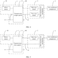
FIG. 4 is a schematic diagram of a structure in which the two connection mechanisms inFIG. 2 are respectively a one-way clutch and a two-way clutch; -
FIG. 5 is a schematic diagram of a structure in which the two connection mechanisms inFIG. 2 are respectively a one-way clutch and an integral shaft; -
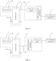
FIG. 6 is a schematic diagram of a structure in which a transmission system in an electric vehicle drive system includes one transmission mechanism and one connection mechanism connected to an input shaft of a transmission according to an embodiment of this invention; -
FIG. 7 is a schematic diagram of a structure in which a transmission system in an electric vehicle drive system includes one connection mechanism and one transmission mechanism connected to a countershaft of a transmission according to an embodiment of this invention; -
FIG. 8 is a schematic diagram of a structure in which the transmission mechanism inFIG. 6 is a belt transmission mechanism and the connection mechanism inFIG. 6 is a two-way clutch; -
FIG. 9 is a schematic diagram of a structure in which the transmission mechanism inFIG. 7 is a belt transmission mechanism and the connection mechanism inFIG. 7 is a two-way clutch; -
FIG. 10 is a schematic diagram of a structure in which a transmission system in an electric vehicle drive system includes one connection mechanism according to an embodiment of this invention; -
FIG. 11 is a schematic diagram of a structure in which a transmission system in an electric vehicle drive system includes one transmission mechanism according to an embodiment of this invention; -
FIG. 12 is a schematic diagram of a structure in which the connection mechanism inFIG. 10 is a two-way clutch; -
FIG. 13 is a schematic diagram of a structure in which the transmission mechanism inFIG. 11 is a belt transmission mechanism; -
FIG. 14 is a schematic diagram of a structure in which a drive motor in an electric vehicle drive system is a dual output shaft motor and a transmission system includes one connection mechanism according to an embodiment of this invention; and -
FIG. 15 is a schematic diagram of a structure in which the connection mechanism inFIG. 14 is a two-way clutch. - 1-powertrain; 10-drive motor; 11-transmission; 110-output axle shaft; 2-transmission system; 20, 20a, and 20b-connection mechanism; 21-transmission mechanism; 3-air-conditioner compressor; 4-first power output mechanism; 40-input shaft; 41-countershaft.
- To make the objectives, technical solutions, and advantages of this invention clearer, the following further describes this invention in detail with reference to the accompanying drawings.
- Terms used in the following embodiments are merely intended to describe specific embodiments, but are not intended to limit this invention. As used in the specification and appended claims of the invention, singular expressions "one", "a", "the", "the foregoing", "this", and "the one" are also intended to include expressions such as "one or more", unless the contrary is clearly indicated in its context.
- Reference to "one embodiment" or "some embodiments" described in this specification or the like means that one or more embodiments of this invention include a particular feature, structure, or characteristic described in combination with the embodiment. Thus, phrases "in one embodiment", "in some embodiments", "in some other embodiments", "in some additional embodiments", and the like that appear in different parts in this specification do not necessarily mean referring to a same embodiment, but mean "one or more embodiments, but not all embodiments", unless otherwise specifically emphasized. The terms "include", "contain", "have", and their variants all mean "include but are not limited to", unless otherwise specifically emphasized.
- With the development of an electric vehicle, requirements for comfort and endurance mileage of the electric vehicle are increasingly high, and disposition of an air conditioner is an important manifestation of comfort. However, when an air conditioner is disposed inside the electric vehicle, a drive motor configured to drive an air-conditioner compressor needs to be separately disposed. The drive motor occupies a part of space inside the electric vehicle. In addition, the air-conditioner compressor is driven by one separate drive motor, and therefore power consumption of the electric vehicle is increased, and endurance mileage of the electric vehicle is reduced.
- Based on the problems above, an embodiment of this invention provides an electric vehicle drive system. Referring to
FIG. 1 , the electric vehicle drive system may include apowertrain 1 and atransmission system 2. Thepowertrain 1 includes a first power output mechanism and a second power output mechanism, the second power output mechanism may be configured to drive an electric vehicle to travel, and the first power output mechanism drives, through the transmission system, an air-conditioner compressor 3 to work. When thepowertrain 1 drives the electric vehicle to travel, a part of power of thepowertrain 1 is also transmitted to the air-conditioner compressor 3 through thetransmission system 2, to drive the air-conditioner compressor to work. In this case, both a power source for traveling of the electric vehicle and a power source of the air-conditioner compressor 3 are thepowertrain 1, and therefore no motor needs to be separately disposed for the air-conditioner compressor 3, and no motor configuration space needs to be reserved, thereby reducing a weight of the electric vehicle and costs of the electric vehicle. In addition, this driving manner can also reduce power consumption. - In some embodiments, the powertrain may include a drive motor and a transmission. The transmission is connected to an output shaft of the drive motor, the first power output mechanism may be disposed on the drive motor or the transmission, and the second power output mechanism is connected to an output end of the transmission. The transmission system may include a transmission mechanism and/or at least one connection mechanism. The connection mechanism can be configured as one of an integral shaft, a button, a slide, a one-way clutch, a two-way clutch, or a synchro. The transmission mechanism can be configured as a gear transmission mechanism, a belt transmission mechanism, or a chain transmission mechanism. The transmission is one of a single-speed transmission, a two-speed transmission, or a multi-speed transmission.
- Specifically, referring to
FIG. 2 , thetransmission system 2 may include twoconnection mechanisms transmission mechanism 21. An output shaft of adrive motor 10 in thepowertrain 1 is connected to aninput shaft 40 of atransmission 11. A firstpower output mechanism 4 may be theinput shaft 40 and acountershaft 41 of thetransmission 11. One end of theconnection mechanism 20a is connected to theinput shaft 40, and the other end of theconnection mechanism 20a is connected to thetransmission mechanism 21. One end of theother connection mechanism 20b is connected to thecountershaft 41, and the other end of theother connection mechanism 20b is connected to thetransmission mechanism 21. Thetransmission mechanism 21 is configured to be connected to the air-conditioner compressor 3. In this way, when driving thetransmission 11, thedrive motor 10 can also supply power to the two connection mechanisms through theinput shaft 40 and thecountershaft 41 of thetransmission 11. Because thetransmission mechanism 21 is configured to connect the two connection mechanisms to the air-conditioner compressor 3, the air-conditioner compressor 3 is enabled to work. - Referring to
FIG. 2 and FIG. 3 together, in thetransmission system 2, both the twoconnection mechanisms transmission mechanism 21 may be a gear transmission mechanism. In this case, thetransmission 11 in thepowertrain 1 may be a two-speed transmission 11. Aninput shaft 40 of the two-speed transmission 11 is connected to one two-way clutch, acountershaft 41 of the two-speed transmission 11 is connected to the other two-way clutch, both the two-way clutches are connected to the gear transmission mechanism, and the gear transmission mechanism is connected to the air-conditioner compressor 3. - When the electric vehicle normally travels, the
drive motor 10 rotates forward, so that power is transmitted to the two-speed transmission 11 through theinput shaft 40 of the two-speed transmission 11, and the power is output to an output axle shaft 110 (the second power output mechanism) of the two-speed transmission 11 through transmission of a gear inside the two-speed transmission 11, to be supplied to the electric vehicle for traveling. If an air conditioner needs to be turned on, and a rotational speed of thedrive motor 10 is relatively low and meets a rotational speed requirement of the air-conditioner compressor 3, the two-way clutch connected to theinput shaft 40 of the two-speed transmission 11 is engaged, and the two-way clutch connected to thecountershaft 41 of the two-speed transmission 11 is disengaged, so that power output by thedrive motor 10 drives, through theinput shaft 40 of the two-speed transmission 11, the two-way clutch connected to theinput shaft 40 to rotate, and the power is transmitted to the air-conditioner compressor 3 through the gear transmission mechanism, to drive the air-conditioner compressor 3 to operate. If an air conditioner needs to be turned on, and a rotational speed of thedrive motor 10 is higher than a rotational speed requirement of the air-conditioner compressor 3, the two-way clutch connected to theinput shaft 40 of the two-speed transmission 11 is disengaged, and the two-way clutch connected to thecountershaft 41 of the two-speed transmission 11 is engaged, so that power output by thedrive motor 10 drives, through thecountershaft 41 of the two-speed transmission 11, the two-way clutch connected to thecountershaft 41 to rotate, and the power is transmitted to the air-conditioner compressor 3 after a transmission rotational speed is reduced through the gear transmission mechanism, to drive the air-conditioner compressor 3 to work. - In addition, when the electric vehicle is in a reverse state, to protect the air-
conditioner compressor 3 from reversely rotating, both the two-way clutches are enabled to be in a disengaged state. - When the vehicle is in a parked state, the two-
speed transmission 11 is in a neutral gear state. If the air conditioner needs to be turned on, thedrive motor 10 rotates forward to drive theinput shaft 40 of the two-speed transmission 11 to rotate, the two-way clutch connected to theinput shaft 40 is engaged, and the two-way clutch connected to thecountershaft 41 of the two-speed transmission 11 is disengaged, so that power output by thedrive motor 10 can be transmitted to the air-conditioner compressor 3 through the two-way clutch connected to theinput shaft 40. - Referring to
FIG. 2 andFIG. 4 together, in the foregoing embodiment, in thetransmission system 2, the twoconnection mechanisms transmission mechanism 21 may be a belt transmission mechanism. In this case, thetransmission 11 in thepowertrain 1 may be a single-speed transmission 11. The one-way clutch is connected to aninput shaft 40 of the single-speed transmission 11, the two-way clutch is connected to acountershaft 41 of the single-speed transmission 11, both the one-way clutch and the two-way clutch are connected to the belt transmission mechanism, and the belt transmission mechanism is configured to be connected to the air-conditioner compressor 3. - When the electric vehicle normally travels forward, the
drive motor 10 rotates forward, so that power is transmitted to the single-speed transmission 11, and the power is output to an output axle shaft 110 (the second power output mechanism) of the single-speed transmission 11 through transmission of a gear inside the single-speed transmission 11, to drive the electric vehicle to travel forward. If an air conditioner needs to be turned on, the one-way clutch connected to theinput shaft 40 of the single-speed transmission 11 is disengaged, and the two-way clutch connected to thecountershaft 41 of the single-speed transmission 11 is engaged, so that power output by thedrive motor 10 drives, through thecountershaft 41 of the single-speed transmission 11, the two-way clutch to rotate, and the power is transmitted to the air-conditioner compressor 3 after a rotational speed is changed through the belt transmission mechanism, to drive the air-conditioner compressor to operate. - When the electric vehicle is in a reverse state, the
drive motor 10 reversely rotates, the one-way clutch is engaged, and the two-way clutch connected to thecountershaft 41 of the single-speed transmission 11 is disengaged. In this case, the air-conditioner compressor 3 can normally operate. In this way, power output by thedrive motor 10 is transmitted to the one-way clutch through theinput shaft 40 of the single-speed transmission 11, to drive, through the belt transmission mechanism, the air-conditioner compressor 3 to operate. - When the electric vehicle is in a parked state, if the air conditioner needs to be turned on, the single-
speed transmission 11 is in a neutral gear state, thedrive motor 10 reversely rotates, thedrive motor 10 drives theinput shaft 40 of the single-speed transmission 11 to rotate, the one-way clutch connected to theinput shaft 40 is in an engaged state, and the two-way clutch connected to thecountershaft 41 of the single-speed transmission 11 is disengaged, so that power can be transmitted to the air-conditioner compressor 3 through the one-way clutch and the belt transmission mechanism. - Referring to
FIG. 2 andFIG. 5 together, in the foregoing embodiment, alternatively, in thetransmission system 2, the twoconnection mechanisms transmission mechanism 21 may be a disconnectable belt transmission mechanism. In this case, thetransmission 11 in thepowertrain 1 may be a two-speed transmission 11. Aninput shaft 40 of the two-speed transmission 11 is connected to one end of the one-way clutch, and the other end of the one-way clutch is connected to the belt transmission mechanism. Acountershaft 41 of the two-speed transmission 11 is connected to the belt transmission mechanism through the integral shaft, and the belt transmission mechanism is connected to the air-conditioner compressor 3. - When the electric vehicle normally travels forward, the
drive motor 10 rotates forward, so that power is transmitted to the two-speed transmission 11, and the power is transmitted to an output axle shaft 110 (the second power output mechanism) of the two-speed transmission 11 through transmission of a gear inside the two-speed transmission 11, to drive the electric vehicle to travel forward. If an air conditioner needs to be turned on, the one-way clutch connected to theinput shaft 40 is disengaged, and the belt transmission mechanism is engaged, so that power output by thedrive motor 10 is transmitted to the belt transmission mechanism through thecountershaft 41 of the two-speed transmission 11 and the integral shaft connected to thecountershaft 41, and the power is transmitted to the air-conditioner compressor 3 after a rotational speed is changed through the belt transmission mechanism, to drive the air-conditioner compressor 3 to operate. - When the electric vehicle is in a reverse state, the
drive motor 10 reversely rotates. In this case, the one-way clutch connected to theinput shaft 40 of the two-speed transmission 11 is engaged, and the belt transmission mechanism is disengaged, so that power of thedrive motor 10 is transmitted to the one-way clutch through theinput shaft 40 of the two-speed transmission 11, and is transmitted to the air-conditioner compressor 3 through the belt transmission mechanism, to drive the air-conditioner compressor 3 to rotate. In this way, the air-conditioner compressor 3 can normally operate when the electric vehicle is driven in reverse. - When the electric vehicle is in a parked state and the air conditioner needs to be turned on, the two-
speed transmission 11 is in a neutral gear, thedrive motor 10 reversely rotates, the one-way clutch connected to theinput shaft 40 of the two-speed transmission 11 is engaged, and the belt transmission mechanism is disengaged. In this case, theinput shaft 40 of the two-speed transmission 11 is driven to rotate, and theinput shaft 40 drives the one-way clutch to rotate, so that power can be transmitted to the air-conditioner compressor 3 through the one-way clutch and the belt transmission mechanism, to enable the air-conditioner compressor 3 to operate. - Referring to
FIG. 6 and FIG. 7 , in some embodiments, thetransmission system 2 may alternatively include oneconnection mechanism 20 and onetransmission mechanism 21, and the first power output mechanism may be aninput shaft 40 or acountershaft 41 of atransmission 11. Specifically, when one end of theconnection mechanism 20 is connected to theinput shaft 40 or thecountershaft 41, the other end of theconnection mechanism 20 is connected to thetransmission mechanism 21, and thetransmission mechanism 21 is configured to be connected to the air-conditioner compressor 3, to transmit power of adrive motor 10 in thepowertrain 1 to the air-conditioner compressor 3 to enable the air-conditioner compressor 3 to work. Alternatively, one end of thetransmission mechanism 21 is connected to theinput shaft 40 or thecountershaft 41, the other end of thetransmission mechanism 21 is connected to theconnection mechanism 20, and theconnection mechanism 20 is configured to be connected to the air-conditioner compressor 3, to transmit power to the air-conditioner compressor 3 to enable the air-conditioner compressor 3 to work. - Referring to
FIG. 6 andFIG. 8 , for example, one end of theconnection mechanism 20 is connected to theinput shaft 40. In the foregoing embodiment, theconnection mechanism 20 may be a two-way clutch, and thetransmission mechanism 21 may be a belt transmission mechanism. In this case, the transmission in thepowertrain 1 may be a two-speed transmission 11. One end of aninput shaft 40 of the two-speed transmission 11 is connected to an output shaft of thedrive motor 10, the other end of theinput shaft 40 of the two-speed transmission 11 is connected to one end of the two-way clutch, the other end of the two-way clutch is connected to the belt transmission mechanism, and the belt transmission mechanism is connected to the air-conditioner compressor 3. - When the electric vehicle normally travels forward, the
drive motor 10 rotates forward, so that power is transmitted to the two-speed transmission 11, and the power is output to an output axle shaft 110 (the second power output mechanism) of the two-speed transmission 11 through transmission of a gear inside the two-speed transmission 11, to be supplied to the electric vehicle for traveling forward. If an air conditioner needs to be turned on, the two-way clutch connected to theinput shaft 40 of the two-speed transmission 11 is engaged, so that power output by thedrive motor 10 drives, through theinput shaft 40 of the two-speed transmission 11, the two-way clutch to rotate, and the power is transmitted to the air-conditioner compressor 3 after a rotational speed is changed through the belt transmission mechanism, to drive the air-conditioner compressor 3 to operate. - When the electric vehicle is in a reverse state, the
drive motor 10 reversely rotates. To protect the air-conditioner compressor 3 from reversely rotating, the two-way clutch connected to the two-speed transmission 11 is disengaged. - When the electric vehicle is in a parked state, if the air conditioner needs to be turned on, the two-
speed transmission 11 is enabled to be in a neutral gear, thedrive motor 10 rotates forward to drive the input shaft of the two-speed transmission 11 to rotate, and the two-way clutch is engaged, so that power of thedrive motor 10 can be transmitted to the belt transmission mechanism through the two-way clutch, and then transmitted to the air-conditioner compressor 3. - Referring to
FIG. 7 andFIG. 9 , for example, one end of thetransmission mechanism 21 is connected to thecountershaft 41. In the foregoing embodiment, theconnection mechanism 20 may be a two-way clutch, and thetransmission mechanism 21 may be a belt transmission mechanism. In this case, thetransmission 11 in thepowertrain 1 may be a single-speed transmission 11. Acountershaft 41 of the single-speed transmission 11 is connected to the belt transmission mechanism, and the two-way clutch is configured to connect the belt transmission mechanism to the air-conditioner compressor 3. - When the electric vehicle normally travels forward, the
drive motor 10 rotates forward, so that power is transmitted to the single-speed transmission 11, and the power is transmitted to an output axle shaft 110 (the second power output mechanism) of the single-speed transmission 11 through transmission of a gear inside the single-speed transmission 11, to drive the electric vehicle to travel forward. If an air conditioner needs to be turned on, the two-way clutch connected to the belt transmission mechanism is engaged, so that power output by thedrive motor 10 is transmitted to the belt transmission mechanism through thecountershaft 41 of the single-speed transmission 11, and the power is transmitted to the two-way clutch after a rotational speed is changed through the belt transmission mechanism, to drive the air-conditioner compressor 3 to operate. - When the electric vehicle is in a reverse state, the
drive motor 10 reversely rotates. To protect the air-conditioner compressor 3 from reversely rotating, the two-way clutch connected to the belt transmission mechanism needs to be disengaged. - When the electric vehicle is in a parked state, if the air conditioner needs to be turned on, the single-
speed transmission 11 is in a neutral gear state, thedrive motor 10 rotates forward to drive thecountershaft 41 of the single-speed transmission 11 to rotate, and the two-way clutch connected to the belt transmission mechanism is engaged, so that power output by the drive motor is transmitted to the belt transmission mechanism through thecountershaft 41 of the single-speed transmission 11, and the power is transmitted to the two-way clutch after a rotational speed is changed through the belt transmission mechanism, to drive the air-conditioner compressor 3 to operate. - Referring to
FIG. 10 and FIG. 11 , in some embodiments, thetransmission system 2 may alternatively include oneconnection mechanism 20 or onetransmission mechanism 21, and the first power output mechanism may be an input shaft (not shown in the figure) or acountershaft 41 of atransmission 11. Specifically, when thetransmission system 2 includes theconnection mechanism 20, one end of theconnection mechanism 20 may be connected to the input shaft or thecountershaft 41, and the other end of theconnection mechanism 20 is connected to the air-conditioner compressor 3. When thetransmission system 2 includes thetransmission mechanism 21, one end of thetransmission mechanism 21 is connected to thecountershaft 41 of thetransmission 11, and the other end of thetransmission mechanism 21 is configured to be connected to the air-conditioner compressor 3. - Referring to
FIG. 10 andFIG. 12 , in the foregoing embodiment, when thetransmission system 2 includes theconnection mechanism 20, theconnection mechanism 20 may be a two-way clutch. In this case, thetransmission 11 in thepowertrain 1 may be a single-speed transmission 11. One end of the two-way clutch may be connected to an input shaft (not shown in the figure) or acountershaft 41 of the single-speed transmission 11, and the other end of the two-way clutch is configured to be connected to the air-conditioner compressor 3. - When the electric vehicle normally travels forward, the
drive motor 10 rotates forward, so that power is transmitted to the single-speed transmission 11, and the power is transmitted to an output axle shaft 110 (the second power output mechanism) of the single-speed transmission 11 through transmission of a gear inside the single-speed transmission 11, to drive the electric vehicle to travel forward. If an air conditioner needs to be turned on, the two-way clutch connected to thecountershaft 41 of the single-speed transmission 11 is engaged, so that power output by thedrive motor 10 drives, through thecountershaft 41 of the single-speed transmission 11, the two-way clutch to rotate, to drive the air-conditioner compressor 3 to operate. - When the electric vehicle is in a reverse state, the
drive motor 10 reversely rotates. To protect the air-conditioner compressor 3 from reversely rotating and reduce a loss of the air-conditioner compressor 3, the two-way clutch connected to thecountershaft 41 of the single-speed transmission 11 is disengaged. - When the electric vehicle is in a parked state, if the air conditioner needs to be turned on, the single-
speed transmission 11 is in a neutral gear state, thedrive motor 10 rotates forward, and the two-way clutch connected to thecountershaft 41 of the single-speed transmission 11 is engaged, so that power output by thedrive motor 10 drives, through thecountershaft 41 of the single-speed transmission 11, the two-way clutch to rotate, to drive the air-conditioner compressor 3 to operate. - Referring to
FIG. 11 andFIG. 13 , in the foregoing embodiment, when thetransmission system 2 includes thetransmission mechanism 21, and thetransmission mechanism 21 may be a disconnectable belt transmission mechanism, thetransmission 11 in thepowertrain 1 may be a single-speed transmission 11. One end of the belt transmission mechanism may be connected to acountershaft 41 of the single-speed transmission 11, and the other end of the belt transmission mechanism is configured to be connected to the air-conditioner compressor 3. - When the vehicle normally travels forward, the
drive motor 10 rotates forward, so that power is transmitted to the single-speed transmission 11, and the power is transmitted to an output axle shaft 110 (the second power output mechanism) of the single-speed transmission 11 through transmission of a gear inside the single-speed transmission 11, to drive the electric vehicle to travel forward. If an air conditioner needs to be turned on, the belt transmission mechanism connected to thecountershaft 41 of the single-speed transmission 11 is engaged, so that power output by thedrive motor 10 is transmitted to the belt transmission mechanism through thecountershaft 41 of the single-speed transmission 11, to drive the air-conditioner compressor 3 connected to the belt transmission mechanism to operate. - When the electric vehicle is in a reverse state, the
drive motor 10 reversely rotates. To protect the air-conditioner compressor 3 from reversely rotating and reduce a loss of the air-conditioner compressor 3, the belt transmission mechanism connected to thecountershaft 41 of the single-speed transmission 11 is disengaged, so that power cannot be transmitted to the air-conditioner compressor 3. In this case, the air-conditioner compressor 3 does not work. - When the electric vehicle is in a parked state, if the air conditioner needs to be turned on, the single-
speed transmission 11 may be enabled to be in a neutral gear state, thedrive motor 10 rotates forward to drive thecountershaft 41 of the single-speed transmission 11 to rotate, and the belt transmission mechanism connected to thecountershaft 41 of the single-speed transmission 11 is engaged, so that power output by thedrive motor 10 is transmitted to the belt transmission mechanism through thecountershaft 41 of the single-speed transmission 11, to drive the air-conditioner compressor 3 connected to the belt transmission mechanism to operate. - Referring to
FIG. 14 and FIG. 15 , in some embodiments, adrive motor 10 in thepowertrain 1 may be a dual output shaft motor, thetransmission system 2 includes oneconnection mechanism 20, and atransmission 11 may be a two-speed transmission 11. Theconnection mechanism 20 may be a two-way clutch. One output end of the dual output shaft motor is connected to thetransmission 11, and the other output end (the first power output mechanism) of the dual output shaft motor is connected to the two-way clutch. The two-way clutch is configured to be connected to the air-conditioner compressor 3. - When the electric vehicle normally travels forward, the dual output shaft motor rotates forward, so that the output shaft of the dual output shaft motor transmits power to the two-
speed transmission 11, and the power is transmitted to an output axle shaft 110 (the second power output mechanism) of the two-speed transmission 11 through transmission of a gear inside the two-speed transmission 11, to drive the electric vehicle to travel forward. If an air conditioner needs to be turned on, the two-way clutch connected to the other output shaft of the dual output shaft motor is engaged, and the other output shaft of the dual output shaft motor drives the two-way clutch to rotate, to drive the air-conditioner compressor 3 to operate. - When the vehicle is in a reverse state, the dual output shaft motor reversely rotates. To protect the air-
conditioner compressor 3 from reversely rotating and reduce a loss of the air-conditioner compressor 3, the two-way clutch connected to the other output shaft of the dual output shaft motor is disengaged. - When the vehicle is in a parked state, if the air conditioner needs to be turned on, the two-
speed transmission 11 is in a neutral gear state, the two-way clutch connected to the other output shaft of the dual output shaft motor is engaged, and the other output shaft of the dual output shaft motor drives the two-way clutch to rotate, to drive the air-conditioner compressor 3 to operate. - It should be noted that the transmission further includes a neutral gear mechanism, so that the transmission can be in a neutral gear state. When the transmission system includes one connection mechanism or one transmission mechanism and the transmission is a single-speed transmission, the neutral gear mechanism is a synchro disposed on the input shaft, the neutral gear mechanism is a clutch disposed on the countershaft, or the neutral gear mechanism is a clutch or a synchro disposed on the output shaft or a differential assembly.
- This invention further provides an electric vehicle. The electric vehicle has the electric vehicle drive system in any one of the foregoing solutions. When driving the electric vehicle to travel, a powertrain in this electric vehicle can also drive an air-conditioner compressor to work, thereby reducing power consumption of the electric vehicle. In addition, no motor needs to be separately disposed for the air-conditioner compressor, thereby saving space inside the electric vehicle.
Claims (5)
- An electric vehicle drive system, comprising a powertrain (1) and a transmission system (2), whereinthe powertrain (1) comprises a first power output mechanism (4) and a second power output mechanism, the first power output mechanism (4) is connected to the transmission system (2), and the transmission system (2) is configured to be connected to an air-conditioner compressor (3) in an electric vehicle;the first power output mechanism (4) is configured to drive, through the transmission system (2), the air-conditioner compressor (3) to work; andthe second power output mechanism is configured to drive the electric vehicle to travel;characterized in that the powertrain (1) further comprises a drive motor and a transmission, the transmission comprises an input shaft (40), a countershaft (41), and an output axle shaft (110) that are in transmission connection, and one end of the input shaft (40) is connected to the drive motor; and the first power output mechanism (4) comprises the input shaft (40) and the countershaft (41), and the second power output mechanism comprises the output axle shaft (110);the transmission system (2) comprises two connection mechanisms and one transmission mechanism, wherein two ends of one connection mechanism are respectively connected to the other end of the input shaft (40) and the transmission mechanism;two ends of the other connection mechanism are respectively connected to the countershaft (41) and the transmission mechanism; andthe transmission mechanism is configured to be connected to the air-conditioner compressor (3).
- The electric vehicle drive system according to claim 1, wherein the connection mechanism can be configured as one of an integral shaft, a button, a slide, a one-way clutch, a two-way clutch, or a synchro; and
the transmission mechanism can be configured as one of a gear transmission mechanism, a belt transmission mechanism, or a chain transmission mechanism. - The electric vehicle drive system according to claim 2, wherein both the two connection mechanisms are two-way clutches, and the transmission mechanism is a gear transmission mechanism;in the two connection mechanisms, the connection mechanism connected to the input shaft (40) is a one-way clutch, and the connection mechanism connected to the countershaft (41) is a two-way clutch; and the transmission mechanism is a belt transmission mechanism; orin the two connection mechanisms, the connection mechanism connected to the input shaft (40) is a one-way clutch, and the connection mechanism connected to the countershaft (41) is an integral shaft; and the transmission mechanism is a belt transmission mechanism.
- The electric vehicle drive system according to any one of claims 1 to 3, wherein the transmission is one of a single-speed transmission, a two-speed transmission, or a multi-speed transmission; and
a neutral gear mechanism is disposed on the transmission, and the neutral gear mechanism is disposed on the input shaft (40), the countershaft (41), the output shaft, or a differential assembly in the transmission. - An electric vehicle, comprising the electric vehicle drive system according to any one of claims 1 to 4.
Applications Claiming Priority (1)
| Application Number | Priority Date | Filing Date | Title |
|---|---|---|---|
| PCT/CN2020/125674 WO2022088155A1 (en) | 2020-10-31 | 2020-10-31 | Electric automobile driving system and electric automobile |
Publications (3)
| Publication Number | Publication Date |
|---|---|
| EP4088962A1 EP4088962A1 (en) | 2022-11-16 |
| EP4088962A4 EP4088962A4 (en) | 2023-07-05 |
| EP4088962B1 true EP4088962B1 (en) | 2024-06-19 |
Family
ID=81381694
Family Applications (1)
| Application Number | Title | Priority Date | Filing Date |
|---|---|---|---|
| EP20959316.9A Active EP4088962B1 (en) | 2020-10-31 | 2020-10-31 | Electric automobile driving system and electric automobile |
Country Status (4)
| Country | Link |
|---|---|
| US (1) | US20220379683A1 (en) |
| EP (1) | EP4088962B1 (en) |
| CN (1) | CN115038609B (en) |
| WO (1) | WO2022088155A1 (en) |
Families Citing this family (1)
| Publication number | Priority date | Publication date | Assignee | Title |
|---|---|---|---|---|
| CN116278686A (en) * | 2023-04-03 | 2023-06-23 | 华为数字能源技术有限公司 | Powertrain, motor controller, electric vehicle |
Family Cites Families (12)
| Publication number | Priority date | Publication date | Assignee | Title |
|---|---|---|---|---|
| JP3260302B2 (en) * | 1997-07-24 | 2002-02-25 | ダイハツ工業株式会社 | Compressor drive mechanism for electric vehicle air conditioner |
| KR101135185B1 (en) * | 2009-11-30 | 2012-04-16 | 김용주 | Transmission of electric vehicles |
| US8286534B2 (en) * | 2010-10-12 | 2012-10-16 | Tai-Her Yang | Assembled transmission device with bi-rotating directional input and constant rotating directional output |
| DE112011102477T5 (en) * | 2011-03-31 | 2013-05-02 | Aisin Aw Co., Ltd. | Drive device for an electric vehicle |
| JP5466201B2 (en) * | 2011-06-08 | 2014-04-09 | トヨタ自動車株式会社 | Electric car |
| CN102390260A (en) * | 2011-08-31 | 2012-03-28 | 奇瑞汽车股份有限公司 | Electric vehicle drive and air conditioner system and control method thereof |
| DE102012214200A1 (en) * | 2012-08-09 | 2014-02-13 | Robert Bosch Gmbh | Electric machine for system for air conditioning of motor car, has flange shaft portions formed as drive shaft and driven shaft for generator and motor operation of machine, and overrunning coupling arranged between shaft portions |
| CN204605492U (en) * | 2015-04-20 | 2015-09-02 | 南京林业大学 | A kind of drive system of pure electric automobile air conditioning compressor |
| DE102018119484A1 (en) * | 2018-08-10 | 2020-02-13 | Schaeffler Technologies AG & Co. KG | Electromechanical drive arrangement for a motor vehicle |
| DE102018119486A1 (en) * | 2018-08-10 | 2020-02-13 | Schaeffler Technologies AG & Co. KG | Electromechanical drive arrangement for a motor vehicle |
| CN209126501U (en) * | 2018-11-05 | 2019-07-19 | 苏州睿控电动有限公司 | Electric car integrates power drive system |
| CN109398059A (en) * | 2018-11-05 | 2019-03-01 | 苏州睿控电动有限公司 | Electric car integrates power drive system |
-
2020
- 2020-10-31 WO PCT/CN2020/125674 patent/WO2022088155A1/en not_active Ceased
- 2020-10-31 CN CN202080017820.5A patent/CN115038609B/en active Active
- 2020-10-31 EP EP20959316.9A patent/EP4088962B1/en active Active
-
2022
- 2022-08-10 US US17/884,939 patent/US20220379683A1/en not_active Abandoned
Also Published As
| Publication number | Publication date |
|---|---|
| WO2022088155A1 (en) | 2022-05-05 |
| CN115038609A (en) | 2022-09-09 |
| EP4088962A1 (en) | 2022-11-16 |
| EP4088962A4 (en) | 2023-07-05 |
| US20220379683A1 (en) | 2022-12-01 |
| CN115038609B (en) | 2025-04-29 |
Similar Documents
| Publication | Publication Date | Title |
|---|---|---|
| EP3812617B1 (en) | Transmission, power drive system, and vehicle | |
| US9340098B2 (en) | Transmission system of hybrid electric vehicle | |
| US11181174B2 (en) | Powertrain for electric vehicle | |
| CN116368024B (en) | A speed reducer structure with a disengaging mechanism and a vehicle | |
| CN212499851U (en) | A power system of a dual-motor pure electric vehicle | |
| CN213291965U (en) | Pure electric vehicles bi-motor drive axle assembly | |
| JP7760606B2 (en) | Electric drive assembly, four-wheel drive system and automobile | |
| EP4088962B1 (en) | Electric automobile driving system and electric automobile | |
| KR20240067687A (en) | Torque vectoring device for vehicle | |
| CN215621354U (en) | Coaxial integrated double-motor extra-inferior double-speed-ratio electric drive assembly with disengagement function | |
| US9435402B2 (en) | Planetary gear train of automatic transmission for vehicles | |
| CN215552537U (en) | A single motor electric drive power assembly | |
| CN215552500U (en) | A dual-motor power system and vehicle | |
| CN212250995U (en) | multi-speed transmission | |
| CN120270004A (en) | Electric drive bridge and electric truck | |
| CN212499850U (en) | A dual-motor pure electric power system and vehicle | |
| EP3878673B1 (en) | Hybrid power module and vehicle | |
| CN111734797A (en) | multi-speed transmission | |
| CN102887056A (en) | Dual-mode hybrid power transmission device and hybrid power transmission system | |
| CN110725910B (en) | New energy commercial vehicle EAT derailleur gear drive structure | |
| KR20240067688A (en) | Torque vectoring device for vehicle | |
| CN113844250A (en) | Hybrid transmission, automobile power system and automobile | |
| CN223045534U (en) | Vehicle drive system and vehicle | |
| CN223253072U (en) | Drive system assembly and vehicle | |
| CN217784133U (en) | Pure electric system and vehicle |
Legal Events
| Date | Code | Title | Description |
|---|---|---|---|
| STAA | Information on the status of an ep patent application or granted ep patent |
Free format text: STATUS: THE INTERNATIONAL PUBLICATION HAS BEEN MADE |
|
| PUAI | Public reference made under article 153(3) epc to a published international application that has entered the european phase |
Free format text: ORIGINAL CODE: 0009012 |
|
| STAA | Information on the status of an ep patent application or granted ep patent |
Free format text: STATUS: REQUEST FOR EXAMINATION WAS MADE |
|
| 17P | Request for examination filed |
Effective date: 20220809 |
|
| AK | Designated contracting states |
Kind code of ref document: A1 Designated state(s): AL AT BE BG CH CY CZ DE DK EE ES FI FR GB GR HR HU IE IS IT LI LT LU LV MC MK MT NL NO PL PT RO RS SE SI SK SM TR |
|
| A4 | Supplementary search report drawn up and despatched |
Effective date: 20230602 |
|
| RIC1 | Information provided on ipc code assigned before grant |
Ipc: B60K 1/00 20060101ALI20230529BHEP Ipc: B60H 1/32 20060101ALI20230529BHEP Ipc: B60L 1/00 20060101AFI20230529BHEP |
|
| DAV | Request for validation of the european patent (deleted) | ||
| DAX | Request for extension of the european patent (deleted) | ||
| GRAP | Despatch of communication of intention to grant a patent |
Free format text: ORIGINAL CODE: EPIDOSNIGR1 |
|
| STAA | Information on the status of an ep patent application or granted ep patent |
Free format text: STATUS: GRANT OF PATENT IS INTENDED |
|
| INTG | Intention to grant announced |
Effective date: 20240229 |
|
| GRAS | Grant fee paid |
Free format text: ORIGINAL CODE: EPIDOSNIGR3 |
|
| P01 | Opt-out of the competence of the unified patent court (upc) registered |
Effective date: 20240404 |
|
| GRAA | (expected) grant |
Free format text: ORIGINAL CODE: 0009210 |
|
| STAA | Information on the status of an ep patent application or granted ep patent |
Free format text: STATUS: THE PATENT HAS BEEN GRANTED |
|
| AK | Designated contracting states |
Kind code of ref document: B1 Designated state(s): AL AT BE BG CH CY CZ DE DK EE ES FI FR GB GR HR HU IE IS IT LI LT LU LV MC MK MT NL NO PL PT RO RS SE SI SK SM TR |
|
| REG | Reference to a national code |
Ref country code: GB Ref legal event code: FG4D |
|
| REG | Reference to a national code |
Ref country code: CH Ref legal event code: EP |
|
| REG | Reference to a national code |
Ref country code: DE Ref legal event code: R096 Ref document number: 602020032826 Country of ref document: DE |
|
| PG25 | Lapsed in a contracting state [announced via postgrant information from national office to epo] |
Ref country code: BG Free format text: LAPSE BECAUSE OF FAILURE TO SUBMIT A TRANSLATION OF THE DESCRIPTION OR TO PAY THE FEE WITHIN THE PRESCRIBED TIME-LIMIT Effective date: 20240619 |
|
| PG25 | Lapsed in a contracting state [announced via postgrant information from national office to epo] |
Ref country code: HR Free format text: LAPSE BECAUSE OF FAILURE TO SUBMIT A TRANSLATION OF THE DESCRIPTION OR TO PAY THE FEE WITHIN THE PRESCRIBED TIME-LIMIT Effective date: 20240619 Ref country code: FI Free format text: LAPSE BECAUSE OF FAILURE TO SUBMIT A TRANSLATION OF THE DESCRIPTION OR TO PAY THE FEE WITHIN THE PRESCRIBED TIME-LIMIT Effective date: 20240619 |
|
| REG | Reference to a national code |
Ref country code: LT Ref legal event code: MG9D |
|
| PG25 | Lapsed in a contracting state [announced via postgrant information from national office to epo] |
Ref country code: GR Free format text: LAPSE BECAUSE OF FAILURE TO SUBMIT A TRANSLATION OF THE DESCRIPTION OR TO PAY THE FEE WITHIN THE PRESCRIBED TIME-LIMIT Effective date: 20240920 |
|
| REG | Reference to a national code |
Ref country code: NL Ref legal event code: MP Effective date: 20240619 |
|
| PG25 | Lapsed in a contracting state [announced via postgrant information from national office to epo] |
Ref country code: LV Free format text: LAPSE BECAUSE OF FAILURE TO SUBMIT A TRANSLATION OF THE DESCRIPTION OR TO PAY THE FEE WITHIN THE PRESCRIBED TIME-LIMIT Effective date: 20240619 |
|
| PG25 | Lapsed in a contracting state [announced via postgrant information from national office to epo] |
Ref country code: NO Free format text: LAPSE BECAUSE OF FAILURE TO SUBMIT A TRANSLATION OF THE DESCRIPTION OR TO PAY THE FEE WITHIN THE PRESCRIBED TIME-LIMIT Effective date: 20240919 Ref country code: LV Free format text: LAPSE BECAUSE OF FAILURE TO SUBMIT A TRANSLATION OF THE DESCRIPTION OR TO PAY THE FEE WITHIN THE PRESCRIBED TIME-LIMIT Effective date: 20240619 Ref country code: HR Free format text: LAPSE BECAUSE OF FAILURE TO SUBMIT A TRANSLATION OF THE DESCRIPTION OR TO PAY THE FEE WITHIN THE PRESCRIBED TIME-LIMIT Effective date: 20240619 Ref country code: GR Free format text: LAPSE BECAUSE OF FAILURE TO SUBMIT A TRANSLATION OF THE DESCRIPTION OR TO PAY THE FEE WITHIN THE PRESCRIBED TIME-LIMIT Effective date: 20240920 Ref country code: FI Free format text: LAPSE BECAUSE OF FAILURE TO SUBMIT A TRANSLATION OF THE DESCRIPTION OR TO PAY THE FEE WITHIN THE PRESCRIBED TIME-LIMIT Effective date: 20240619 Ref country code: BG Free format text: LAPSE BECAUSE OF FAILURE TO SUBMIT A TRANSLATION OF THE DESCRIPTION OR TO PAY THE FEE WITHIN THE PRESCRIBED TIME-LIMIT Effective date: 20240619 Ref country code: RS Free format text: LAPSE BECAUSE OF FAILURE TO SUBMIT A TRANSLATION OF THE DESCRIPTION OR TO PAY THE FEE WITHIN THE PRESCRIBED TIME-LIMIT Effective date: 20240919 |
|
| PG25 | Lapsed in a contracting state [announced via postgrant information from national office to epo] |
Ref country code: NL Free format text: LAPSE BECAUSE OF FAILURE TO SUBMIT A TRANSLATION OF THE DESCRIPTION OR TO PAY THE FEE WITHIN THE PRESCRIBED TIME-LIMIT Effective date: 20240619 |
|
| REG | Reference to a national code |
Ref country code: AT Ref legal event code: MK05 Ref document number: 1695722 Country of ref document: AT Kind code of ref document: T Effective date: 20240619 |
|
| PG25 | Lapsed in a contracting state [announced via postgrant information from national office to epo] |
Ref country code: NL Free format text: LAPSE BECAUSE OF FAILURE TO SUBMIT A TRANSLATION OF THE DESCRIPTION OR TO PAY THE FEE WITHIN THE PRESCRIBED TIME-LIMIT Effective date: 20240619 |
|
| PG25 | Lapsed in a contracting state [announced via postgrant information from national office to epo] |
Ref country code: PT Free format text: LAPSE BECAUSE OF FAILURE TO SUBMIT A TRANSLATION OF THE DESCRIPTION OR TO PAY THE FEE WITHIN THE PRESCRIBED TIME-LIMIT Effective date: 20241021 |
|
| PG25 | Lapsed in a contracting state [announced via postgrant information from national office to epo] |
Ref country code: PT Free format text: LAPSE BECAUSE OF FAILURE TO SUBMIT A TRANSLATION OF THE DESCRIPTION OR TO PAY THE FEE WITHIN THE PRESCRIBED TIME-LIMIT Effective date: 20241021 |
|
| PG25 | Lapsed in a contracting state [announced via postgrant information from national office to epo] |
Ref country code: PL Free format text: LAPSE BECAUSE OF FAILURE TO SUBMIT A TRANSLATION OF THE DESCRIPTION OR TO PAY THE FEE WITHIN THE PRESCRIBED TIME-LIMIT Effective date: 20240619 |
|
| PG25 | Lapsed in a contracting state [announced via postgrant information from national office to epo] |
Ref country code: EE Free format text: LAPSE BECAUSE OF FAILURE TO SUBMIT A TRANSLATION OF THE DESCRIPTION OR TO PAY THE FEE WITHIN THE PRESCRIBED TIME-LIMIT Effective date: 20240619 |
|
| PG25 | Lapsed in a contracting state [announced via postgrant information from national office to epo] |
Ref country code: IS Free format text: LAPSE BECAUSE OF FAILURE TO SUBMIT A TRANSLATION OF THE DESCRIPTION OR TO PAY THE FEE WITHIN THE PRESCRIBED TIME-LIMIT Effective date: 20241019 Ref country code: AT Free format text: LAPSE BECAUSE OF FAILURE TO SUBMIT A TRANSLATION OF THE DESCRIPTION OR TO PAY THE FEE WITHIN THE PRESCRIBED TIME-LIMIT Effective date: 20240619 |
|
| PG25 | Lapsed in a contracting state [announced via postgrant information from national office to epo] |
Ref country code: CZ Free format text: LAPSE BECAUSE OF FAILURE TO SUBMIT A TRANSLATION OF THE DESCRIPTION OR TO PAY THE FEE WITHIN THE PRESCRIBED TIME-LIMIT Effective date: 20240619 |
|
| PG25 | Lapsed in a contracting state [announced via postgrant information from national office to epo] |
Ref country code: RO Free format text: LAPSE BECAUSE OF FAILURE TO SUBMIT A TRANSLATION OF THE DESCRIPTION OR TO PAY THE FEE WITHIN THE PRESCRIBED TIME-LIMIT Effective date: 20240619 Ref country code: SK Free format text: LAPSE BECAUSE OF FAILURE TO SUBMIT A TRANSLATION OF THE DESCRIPTION OR TO PAY THE FEE WITHIN THE PRESCRIBED TIME-LIMIT Effective date: 20240619 |
|
| PG25 | Lapsed in a contracting state [announced via postgrant information from national office to epo] |
Ref country code: SM Free format text: LAPSE BECAUSE OF FAILURE TO SUBMIT A TRANSLATION OF THE DESCRIPTION OR TO PAY THE FEE WITHIN THE PRESCRIBED TIME-LIMIT Effective date: 20240619 Ref country code: ES Free format text: LAPSE BECAUSE OF FAILURE TO SUBMIT A TRANSLATION OF THE DESCRIPTION OR TO PAY THE FEE WITHIN THE PRESCRIBED TIME-LIMIT Effective date: 20240619 |
|
| PG25 | Lapsed in a contracting state [announced via postgrant information from national office to epo] |
Ref country code: SM Free format text: LAPSE BECAUSE OF FAILURE TO SUBMIT A TRANSLATION OF THE DESCRIPTION OR TO PAY THE FEE WITHIN THE PRESCRIBED TIME-LIMIT Effective date: 20240619 Ref country code: SK Free format text: LAPSE BECAUSE OF FAILURE TO SUBMIT A TRANSLATION OF THE DESCRIPTION OR TO PAY THE FEE WITHIN THE PRESCRIBED TIME-LIMIT Effective date: 20240619 Ref country code: RO Free format text: LAPSE BECAUSE OF FAILURE TO SUBMIT A TRANSLATION OF THE DESCRIPTION OR TO PAY THE FEE WITHIN THE PRESCRIBED TIME-LIMIT Effective date: 20240619 Ref country code: PL Free format text: LAPSE BECAUSE OF FAILURE TO SUBMIT A TRANSLATION OF THE DESCRIPTION OR TO PAY THE FEE WITHIN THE PRESCRIBED TIME-LIMIT Effective date: 20240619 Ref country code: IS Free format text: LAPSE BECAUSE OF FAILURE TO SUBMIT A TRANSLATION OF THE DESCRIPTION OR TO PAY THE FEE WITHIN THE PRESCRIBED TIME-LIMIT Effective date: 20241019 Ref country code: ES Free format text: LAPSE BECAUSE OF FAILURE TO SUBMIT A TRANSLATION OF THE DESCRIPTION OR TO PAY THE FEE WITHIN THE PRESCRIBED TIME-LIMIT Effective date: 20240619 Ref country code: EE Free format text: LAPSE BECAUSE OF FAILURE TO SUBMIT A TRANSLATION OF THE DESCRIPTION OR TO PAY THE FEE WITHIN THE PRESCRIBED TIME-LIMIT Effective date: 20240619 Ref country code: CZ Free format text: LAPSE BECAUSE OF FAILURE TO SUBMIT A TRANSLATION OF THE DESCRIPTION OR TO PAY THE FEE WITHIN THE PRESCRIBED TIME-LIMIT Effective date: 20240619 Ref country code: AT Free format text: LAPSE BECAUSE OF FAILURE TO SUBMIT A TRANSLATION OF THE DESCRIPTION OR TO PAY THE FEE WITHIN THE PRESCRIBED TIME-LIMIT Effective date: 20240619 |
|
| PG25 | Lapsed in a contracting state [announced via postgrant information from national office to epo] |
Ref country code: IT Free format text: LAPSE BECAUSE OF FAILURE TO SUBMIT A TRANSLATION OF THE DESCRIPTION OR TO PAY THE FEE WITHIN THE PRESCRIBED TIME-LIMIT Effective date: 20240619 |
|
| REG | Reference to a national code |
Ref country code: DE Ref legal event code: R097 Ref document number: 602020032826 Country of ref document: DE |
|
| PG25 | Lapsed in a contracting state [announced via postgrant information from national office to epo] |
Ref country code: DK Free format text: LAPSE BECAUSE OF FAILURE TO SUBMIT A TRANSLATION OF THE DESCRIPTION OR TO PAY THE FEE WITHIN THE PRESCRIBED TIME-LIMIT Effective date: 20240619 |
|
| PLBE | No opposition filed within time limit |
Free format text: ORIGINAL CODE: 0009261 |
|
| STAA | Information on the status of an ep patent application or granted ep patent |
Free format text: STATUS: NO OPPOSITION FILED WITHIN TIME LIMIT |
|
| 26N | No opposition filed |
Effective date: 20250320 |
|
| REG | Reference to a national code |
Ref country code: CH Ref legal event code: PL |
|
| GBPC | Gb: european patent ceased through non-payment of renewal fee |
Effective date: 20241031 |
|
| PG25 | Lapsed in a contracting state [announced via postgrant information from national office to epo] |
Ref country code: MC Free format text: LAPSE BECAUSE OF FAILURE TO SUBMIT A TRANSLATION OF THE DESCRIPTION OR TO PAY THE FEE WITHIN THE PRESCRIBED TIME-LIMIT Effective date: 20240619 |
|
| PG25 | Lapsed in a contracting state [announced via postgrant information from national office to epo] |
Ref country code: GB Free format text: LAPSE BECAUSE OF NON-PAYMENT OF DUE FEES Effective date: 20241031 |
|
| PG25 | Lapsed in a contracting state [announced via postgrant information from national office to epo] |
Ref country code: BE Free format text: LAPSE BECAUSE OF NON-PAYMENT OF DUE FEES Effective date: 20241031 Ref country code: LU Free format text: LAPSE BECAUSE OF NON-PAYMENT OF DUE FEES Effective date: 20241031 |
|
| PG25 | Lapsed in a contracting state [announced via postgrant information from national office to epo] |
Ref country code: CH Free format text: LAPSE BECAUSE OF NON-PAYMENT OF DUE FEES Effective date: 20241031 |
|
| REG | Reference to a national code |
Ref country code: BE Ref legal event code: MM Effective date: 20241031 |
|
| PG25 | Lapsed in a contracting state [announced via postgrant information from national office to epo] |
Ref country code: SE Free format text: LAPSE BECAUSE OF FAILURE TO SUBMIT A TRANSLATION OF THE DESCRIPTION OR TO PAY THE FEE WITHIN THE PRESCRIBED TIME-LIMIT Effective date: 20240619 |
|
| PGFP | Annual fee paid to national office [announced via postgrant information from national office to epo] |
Ref country code: FR Payment date: 20250908 Year of fee payment: 6 |
|
| PG25 | Lapsed in a contracting state [announced via postgrant information from national office to epo] |
Ref country code: IE Free format text: LAPSE BECAUSE OF NON-PAYMENT OF DUE FEES Effective date: 20241031 |
|
| PGFP | Annual fee paid to national office [announced via postgrant information from national office to epo] |
Ref country code: DE Payment date: 20250902 Year of fee payment: 6 |
|
| PG25 | Lapsed in a contracting state [announced via postgrant information from national office to epo] |
Ref country code: HU Free format text: LAPSE BECAUSE OF FAILURE TO SUBMIT A TRANSLATION OF THE DESCRIPTION OR TO PAY THE FEE WITHIN THE PRESCRIBED TIME-LIMIT; INVALID AB INITIO Effective date: 20201031 |
|
| PG25 | Lapsed in a contracting state [announced via postgrant information from national office to epo] |
Ref country code: CY Free format text: LAPSE BECAUSE OF FAILURE TO SUBMIT A TRANSLATION OF THE DESCRIPTION OR TO PAY THE FEE WITHIN THE PRESCRIBED TIME-LIMIT; INVALID AB INITIO Effective date: 20201031 |