EP4088924A1 - Reinforcing vibration-damping material and reinforcing vibration-damping structure - Google Patents
Reinforcing vibration-damping material and reinforcing vibration-damping structure Download PDFInfo
- Publication number
- EP4088924A1 EP4088924A1 EP20912144.1A EP20912144A EP4088924A1 EP 4088924 A1 EP4088924 A1 EP 4088924A1 EP 20912144 A EP20912144 A EP 20912144A EP 4088924 A1 EP4088924 A1 EP 4088924A1
- Authority
- EP
- European Patent Office
- Prior art keywords
- vibration
- reinforcing
- damping
- layer
- thickness direction
- Prior art date
- Legal status (The legal status is an assumption and is not a legal conclusion. Google has not performed a legal analysis and makes no representation as to the accuracy of the status listed.)
- Pending
Links
- 238000013016 damping Methods 0.000 title claims abstract description 217
- 239000000463 material Substances 0.000 title claims abstract description 140
- 230000003014 reinforcing effect Effects 0.000 title claims abstract description 96
- 239000012779 reinforcing material Substances 0.000 claims abstract description 82
- 229920005989 resin Polymers 0.000 claims description 158
- 239000011347 resin Substances 0.000 claims description 158
- 230000002787 reinforcement Effects 0.000 claims description 105
- 229920001187 thermosetting polymer Polymers 0.000 claims description 25
- 239000004088 foaming agent Substances 0.000 claims description 20
- 229920005549 butyl rubber Polymers 0.000 claims description 11
- 238000006073 displacement reaction Methods 0.000 abstract description 17
- 239000003822 epoxy resin Substances 0.000 description 33
- 229920000647 polyepoxide Polymers 0.000 description 33
- VTYYLEPIZMXCLO-UHFFFAOYSA-L Calcium carbonate Chemical compound [Ca+2].[O-]C([O-])=O VTYYLEPIZMXCLO-UHFFFAOYSA-L 0.000 description 22
- 239000003795 chemical substances by application Substances 0.000 description 18
- 238000004073 vulcanization Methods 0.000 description 18
- 239000000945 filler Substances 0.000 description 14
- 238000002156 mixing Methods 0.000 description 14
- 238000012360 testing method Methods 0.000 description 14
- 229910000019 calcium carbonate Inorganic materials 0.000 description 11
- 229920003244 diene elastomer Polymers 0.000 description 11
- 239000011342 resin composition Substances 0.000 description 11
- 230000000052 comparative effect Effects 0.000 description 10
- LNEPOXFFQSENCJ-UHFFFAOYSA-N haloperidol Chemical compound C1CC(O)(C=2C=CC(Cl)=CC=2)CCN1CCCC(=O)C1=CC=C(F)C=C1 LNEPOXFFQSENCJ-UHFFFAOYSA-N 0.000 description 8
- 238000010438 heat treatment Methods 0.000 description 8
- 229920000459 Nitrile rubber Polymers 0.000 description 7
- 239000006229 carbon black Substances 0.000 description 7
- 239000003208 petroleum Substances 0.000 description 7
- -1 preferably Polymers 0.000 description 7
- 238000005452 bending Methods 0.000 description 6
- IISBACLAFKSPIT-UHFFFAOYSA-N bisphenol A Chemical compound C=1C=C(O)C=CC=1C(C)(C)C1=CC=C(O)C=C1 IISBACLAFKSPIT-UHFFFAOYSA-N 0.000 description 6
- RAXXELZNTBOGNW-UHFFFAOYSA-N imidazole Natural products C1=CNC=N1 RAXXELZNTBOGNW-UHFFFAOYSA-N 0.000 description 6
- NBOCQTNZUPTTEI-UHFFFAOYSA-N 4-[4-(hydrazinesulfonyl)phenoxy]benzenesulfonohydrazide Chemical compound C1=CC(S(=O)(=O)NN)=CC=C1OC1=CC=C(S(=O)(=O)NN)C=C1 NBOCQTNZUPTTEI-UHFFFAOYSA-N 0.000 description 5
- 229920001971 elastomer Polymers 0.000 description 5
- 238000011156 evaluation Methods 0.000 description 5
- 239000007788 liquid Substances 0.000 description 5
- 229910052751 metal Inorganic materials 0.000 description 5
- 239000002184 metal Substances 0.000 description 5
- 238000000034 method Methods 0.000 description 5
- 239000005060 rubber Substances 0.000 description 5
- 239000000126 substance Substances 0.000 description 5
- XEEYBQQBJWHFJM-UHFFFAOYSA-N Iron Chemical compound [Fe] XEEYBQQBJWHFJM-UHFFFAOYSA-N 0.000 description 4
- 229910000831 Steel Inorganic materials 0.000 description 4
- NINIDFKCEFEMDL-UHFFFAOYSA-N Sulfur Chemical compound [S] NINIDFKCEFEMDL-UHFFFAOYSA-N 0.000 description 4
- 125000001931 aliphatic group Chemical group 0.000 description 4
- 229910052782 aluminium Inorganic materials 0.000 description 4
- XAGFODPZIPBFFR-UHFFFAOYSA-N aluminium Chemical compound [Al] XAGFODPZIPBFFR-UHFFFAOYSA-N 0.000 description 4
- 229920001083 polybutene Polymers 0.000 description 4
- 239000010959 steel Substances 0.000 description 4
- XZMCDFZZKTWFGF-UHFFFAOYSA-N Cyanamide Chemical compound NC#N XZMCDFZZKTWFGF-UHFFFAOYSA-N 0.000 description 3
- 239000005062 Polybutadiene Substances 0.000 description 3
- VYPSYNLAJGMNEJ-UHFFFAOYSA-N Silicium dioxide Chemical compound O=[Si]=O VYPSYNLAJGMNEJ-UHFFFAOYSA-N 0.000 description 3
- FZWLAAWBMGSTSO-UHFFFAOYSA-N Thiazole Chemical compound C1=CSC=N1 FZWLAAWBMGSTSO-UHFFFAOYSA-N 0.000 description 3
- 150000001412 amines Chemical class 0.000 description 3
- 125000003118 aryl group Chemical group 0.000 description 3
- 239000004744 fabric Substances 0.000 description 3
- 150000002739 metals Chemical class 0.000 description 3
- 229920003986 novolac Polymers 0.000 description 3
- 239000003921 oil Substances 0.000 description 3
- 229920002857 polybutadiene Polymers 0.000 description 3
- 229920003048 styrene butadiene rubber Polymers 0.000 description 3
- 239000011593 sulfur Substances 0.000 description 3
- 229910052717 sulfur Inorganic materials 0.000 description 3
- 229920003002 synthetic resin Polymers 0.000 description 3
- 239000000057 synthetic resin Substances 0.000 description 3
- 150000003505 terpenes Chemical class 0.000 description 3
- 235000007586 terpenes Nutrition 0.000 description 3
- LLPKQRMDOFYSGZ-UHFFFAOYSA-N 2,5-dimethyl-1h-imidazole Chemical compound CC1=CN=C(C)N1 LLPKQRMDOFYSGZ-UHFFFAOYSA-N 0.000 description 2
- OZAIFHULBGXAKX-UHFFFAOYSA-N 2-(2-cyanopropan-2-yldiazenyl)-2-methylpropanenitrile Chemical compound N#CC(C)(C)N=NC(C)(C)C#N OZAIFHULBGXAKX-UHFFFAOYSA-N 0.000 description 2
- RSWGJHLUYNHPMX-UHFFFAOYSA-N Abietic-Saeure Natural products C12CCC(C(C)C)=CC2=CCC2C1(C)CCCC2(C)C(O)=O RSWGJHLUYNHPMX-UHFFFAOYSA-N 0.000 description 2
- ATRRKUHOCOJYRX-UHFFFAOYSA-N Ammonium bicarbonate Chemical compound [NH4+].OC([O-])=O ATRRKUHOCOJYRX-UHFFFAOYSA-N 0.000 description 2
- 229930185605 Bisphenol Natural products 0.000 description 2
- KAKZBPTYRLMSJV-UHFFFAOYSA-N Butadiene Chemical compound C=CC=C KAKZBPTYRLMSJV-UHFFFAOYSA-N 0.000 description 2
- OKTJSMMVPCPJKN-UHFFFAOYSA-N Carbon Chemical compound [C] OKTJSMMVPCPJKN-UHFFFAOYSA-N 0.000 description 2
- RYGMFSIKBFXOCR-UHFFFAOYSA-N Copper Chemical compound [Cu] RYGMFSIKBFXOCR-UHFFFAOYSA-N 0.000 description 2
- 239000004593 Epoxy Substances 0.000 description 2
- ZRALSGWEFCBTJO-UHFFFAOYSA-N Guanidine Chemical compound NC(N)=N ZRALSGWEFCBTJO-UHFFFAOYSA-N 0.000 description 2
- UFWIBTONFRDIAS-UHFFFAOYSA-N Naphthalene Chemical compound C1=CC=CC2=CC=CC=C21 UFWIBTONFRDIAS-UHFFFAOYSA-N 0.000 description 2
- KHPCPRHQVVSZAH-HUOMCSJISA-N Rosin Natural products O(C/C=C/c1ccccc1)[C@H]1[C@H](O)[C@@H](O)[C@@H](O)[C@@H](CO)O1 KHPCPRHQVVSZAH-HUOMCSJISA-N 0.000 description 2
- UIIMBOGNXHQVGW-UHFFFAOYSA-M Sodium bicarbonate Chemical compound [Na+].OC([O-])=O UIIMBOGNXHQVGW-UHFFFAOYSA-M 0.000 description 2
- PPBRXRYQALVLMV-UHFFFAOYSA-N Styrene Chemical compound C=CC1=CC=CC=C1 PPBRXRYQALVLMV-UHFFFAOYSA-N 0.000 description 2
- 150000008065 acid anhydrides Chemical class 0.000 description 2
- 239000000853 adhesive Substances 0.000 description 2
- 230000001070 adhesive effect Effects 0.000 description 2
- 125000002723 alicyclic group Chemical group 0.000 description 2
- 150000001408 amides Chemical class 0.000 description 2
- 239000001099 ammonium carbonate Substances 0.000 description 2
- 239000004841 bisphenol A epoxy resin Substances 0.000 description 2
- 229910052791 calcium Inorganic materials 0.000 description 2
- 229910052799 carbon Inorganic materials 0.000 description 2
- 229910052802 copper Inorganic materials 0.000 description 2
- 239000010949 copper Substances 0.000 description 2
- QGBSISYHAICWAH-UHFFFAOYSA-N dicyandiamide Chemical compound NC(N)=NC#N QGBSISYHAICWAH-UHFFFAOYSA-N 0.000 description 2
- ZUOUZKKEUPVFJK-UHFFFAOYSA-N diphenyl Chemical compound C1=CC=CC=C1C1=CC=CC=C1 ZUOUZKKEUPVFJK-UHFFFAOYSA-N 0.000 description 2
- 230000000694 effects Effects 0.000 description 2
- 150000002148 esters Chemical class 0.000 description 2
- 239000011521 glass Substances 0.000 description 2
- 239000003365 glass fiber Substances 0.000 description 2
- MTNDZQHUAFNZQY-UHFFFAOYSA-N imidazoline Chemical compound C1CN=CN1 MTNDZQHUAFNZQY-UHFFFAOYSA-N 0.000 description 2
- 229910052742 iron Inorganic materials 0.000 description 2
- 229920003049 isoprene rubber Polymers 0.000 description 2
- 238000004519 manufacturing process Methods 0.000 description 2
- 239000000025 natural resin Substances 0.000 description 2
- 230000000704 physical effect Effects 0.000 description 2
- 230000001629 suppression Effects 0.000 description 2
- UMGDCJDMYOKAJW-UHFFFAOYSA-N thiourea Chemical compound NC(N)=S UMGDCJDMYOKAJW-UHFFFAOYSA-N 0.000 description 2
- KHPCPRHQVVSZAH-UHFFFAOYSA-N trans-cinnamyl beta-D-glucopyranoside Natural products OC1C(O)C(O)C(CO)OC1OCC=CC1=CC=CC=C1 KHPCPRHQVVSZAH-UHFFFAOYSA-N 0.000 description 2
- 230000032258 transport Effects 0.000 description 2
- LTVUCOSIZFEASK-MPXCPUAZSA-N (3ar,4s,7r,7as)-3a-methyl-3a,4,7,7a-tetrahydro-4,7-methano-2-benzofuran-1,3-dione Chemical compound C([C@H]1C=C2)[C@H]2[C@H]2[C@]1(C)C(=O)OC2=O LTVUCOSIZFEASK-MPXCPUAZSA-N 0.000 description 1
- MUTGBJKUEZFXGO-OLQVQODUSA-N (3as,7ar)-3a,4,5,6,7,7a-hexahydro-2-benzofuran-1,3-dione Chemical compound C1CCC[C@@H]2C(=O)OC(=O)[C@@H]21 MUTGBJKUEZFXGO-OLQVQODUSA-N 0.000 description 1
- KMOUUZVZFBCRAM-OLQVQODUSA-N (3as,7ar)-3a,4,7,7a-tetrahydro-2-benzofuran-1,3-dione Chemical compound C1C=CC[C@@H]2C(=O)OC(=O)[C@@H]21 KMOUUZVZFBCRAM-OLQVQODUSA-N 0.000 description 1
- OUPZKGBUJRBPGC-UHFFFAOYSA-N 1,3,5-tris(oxiran-2-ylmethyl)-1,3,5-triazinane-2,4,6-trione Chemical compound O=C1N(CC2OC2)C(=O)N(CC2OC2)C(=O)N1CC1CO1 OUPZKGBUJRBPGC-UHFFFAOYSA-N 0.000 description 1
- UJPKMTDFFUTLGM-UHFFFAOYSA-N 1-aminoethanol Chemical compound CC(N)O UJPKMTDFFUTLGM-UHFFFAOYSA-N 0.000 description 1
- ASLICXGLMBICCD-UHFFFAOYSA-N 1-ethyl-4,5-dihydroimidazole Chemical compound CCN1CCN=C1 ASLICXGLMBICCD-UHFFFAOYSA-N 0.000 description 1
- SPBJUTVLDJRGSY-UHFFFAOYSA-N 1-heptadecyl-4,5-dihydroimidazole Chemical compound CCCCCCCCCCCCCCCCCN1CCN=C1 SPBJUTVLDJRGSY-UHFFFAOYSA-N 0.000 description 1
- ANFXTILBDGTSEG-UHFFFAOYSA-N 1-methyl-4,5-dihydroimidazole Chemical compound CN1CCN=C1 ANFXTILBDGTSEG-UHFFFAOYSA-N 0.000 description 1
- YJBAUTPCBIGXHL-UHFFFAOYSA-N 1-phenyl-4,5-dihydroimidazole Chemical compound C1=NCCN1C1=CC=CC=C1 YJBAUTPCBIGXHL-UHFFFAOYSA-N 0.000 description 1
- SEULWJSKCVACTH-UHFFFAOYSA-N 1-phenylimidazole Chemical compound C1=NC=CN1C1=CC=CC=C1 SEULWJSKCVACTH-UHFFFAOYSA-N 0.000 description 1
- VUDCHJYPASPIJR-UHFFFAOYSA-N 1-propan-2-yl-4,5-dihydroimidazole Chemical compound CC(C)N1CCN=C1 VUDCHJYPASPIJR-UHFFFAOYSA-N 0.000 description 1
- RDBONSWKYPUHCS-UHFFFAOYSA-N 1-undecyl-4,5-dihydroimidazole Chemical compound CCCCCCCCCCCN1CCN=C1 RDBONSWKYPUHCS-UHFFFAOYSA-N 0.000 description 1
- VILCJCGEZXAXTO-UHFFFAOYSA-N 2,2,2-tetramine Chemical compound NCCNCCNCCN VILCJCGEZXAXTO-UHFFFAOYSA-N 0.000 description 1
- PQAMFDRRWURCFQ-UHFFFAOYSA-N 2-ethyl-1h-imidazole Chemical compound CCC1=NC=CN1 PQAMFDRRWURCFQ-UHFFFAOYSA-N 0.000 description 1
- SHYARJUKNREDGB-UHFFFAOYSA-N 2-ethyl-5-methyl-4,5-dihydro-1h-imidazole Chemical compound CCC1=NCC(C)N1 SHYARJUKNREDGB-UHFFFAOYSA-N 0.000 description 1
- YTWBFUCJVWKCCK-UHFFFAOYSA-N 2-heptadecyl-1h-imidazole Chemical compound CCCCCCCCCCCCCCCCCC1=NC=CN1 YTWBFUCJVWKCCK-UHFFFAOYSA-N 0.000 description 1
- LXBGSDVWAMZHDD-UHFFFAOYSA-N 2-methyl-1h-imidazole Chemical compound CC1=NC=CN1 LXBGSDVWAMZHDD-UHFFFAOYSA-N 0.000 description 1
- QTWJRLJHJPIABL-UHFFFAOYSA-N 2-methylphenol;3-methylphenol;4-methylphenol Chemical compound CC1=CC=C(O)C=C1.CC1=CC=CC(O)=C1.CC1=CC=CC=C1O QTWJRLJHJPIABL-UHFFFAOYSA-N 0.000 description 1
- FUOZJYASZOSONT-UHFFFAOYSA-N 2-propan-2-yl-1h-imidazole Chemical compound CC(C)C1=NC=CN1 FUOZJYASZOSONT-UHFFFAOYSA-N 0.000 description 1
- LLEASVZEQBICSN-UHFFFAOYSA-N 2-undecyl-1h-imidazole Chemical compound CCCCCCCCCCCC1=NC=CN1 LLEASVZEQBICSN-UHFFFAOYSA-N 0.000 description 1
- HGFWTERYDVYMMD-UHFFFAOYSA-N 3,3-dichlorooxolane-2,5-dione Chemical compound ClC1(Cl)CC(=O)OC1=O HGFWTERYDVYMMD-UHFFFAOYSA-N 0.000 description 1
- WVRNUXJQQFPNMN-VAWYXSNFSA-N 3-[(e)-dodec-1-enyl]oxolane-2,5-dione Chemical compound CCCCCCCCCC\C=C\C1CC(=O)OC1=O WVRNUXJQQFPNMN-VAWYXSNFSA-N 0.000 description 1
- VPWNQTHUCYMVMZ-UHFFFAOYSA-N 4,4'-sulfonyldiphenol Chemical compound C1=CC(O)=CC=C1S(=O)(=O)C1=CC=C(O)C=C1 VPWNQTHUCYMVMZ-UHFFFAOYSA-N 0.000 description 1
- GRRGMQBIAJCOBQ-UHFFFAOYSA-N 4-(thiatriazol-5-yl)morpholine Chemical compound C1COCCN1C1=NN=NS1 GRRGMQBIAJCOBQ-UHFFFAOYSA-N 0.000 description 1
- VQVIHDPBMFABCQ-UHFFFAOYSA-N 5-(1,3-dioxo-2-benzofuran-5-carbonyl)-2-benzofuran-1,3-dione Chemical compound C1=C2C(=O)OC(=O)C2=CC(C(C=2C=C3C(=O)OC(=O)C3=CC=2)=O)=C1 VQVIHDPBMFABCQ-UHFFFAOYSA-N 0.000 description 1
- TYOXIFXYEIILLY-UHFFFAOYSA-N 5-methyl-2-phenyl-1h-imidazole Chemical compound N1C(C)=CN=C1C1=CC=CC=C1 TYOXIFXYEIILLY-UHFFFAOYSA-N 0.000 description 1
- JJUVAPMVTXLLFR-UHFFFAOYSA-N 5-methyl-2-phenyl-4,5-dihydro-1h-imidazole Chemical compound N1C(C)CN=C1C1=CC=CC=C1 JJUVAPMVTXLLFR-UHFFFAOYSA-N 0.000 description 1
- ULKLGIFJWFIQFF-UHFFFAOYSA-N 5K8XI641G3 Chemical compound CCC1=NC=C(C)N1 ULKLGIFJWFIQFF-UHFFFAOYSA-N 0.000 description 1
- 239000004925 Acrylic resin Substances 0.000 description 1
- 229920000178 Acrylic resin Polymers 0.000 description 1
- 229910000013 Ammonium bicarbonate Inorganic materials 0.000 description 1
- 229910052582 BN Inorganic materials 0.000 description 1
- PZNSFCLAULLKQX-UHFFFAOYSA-N Boron nitride Chemical compound N#B PZNSFCLAULLKQX-UHFFFAOYSA-N 0.000 description 1
- 229910001369 Brass Inorganic materials 0.000 description 1
- MQJKPEGWNLWLTK-UHFFFAOYSA-N Dapsone Chemical compound C1=CC(N)=CC=C1S(=O)(=O)C1=CC=C(N)C=C1 MQJKPEGWNLWLTK-UHFFFAOYSA-N 0.000 description 1
- RPNUMPOLZDHAAY-UHFFFAOYSA-N Diethylenetriamine Chemical compound NCCNCCN RPNUMPOLZDHAAY-UHFFFAOYSA-N 0.000 description 1
- MWRWFPQBGSZWNV-UHFFFAOYSA-N Dinitrosopentamethylenetetramine Chemical compound C1N2CN(N=O)CN1CN(N=O)C2 MWRWFPQBGSZWNV-UHFFFAOYSA-N 0.000 description 1
- PIICEJLVQHRZGT-UHFFFAOYSA-N Ethylenediamine Chemical compound NCCN PIICEJLVQHRZGT-UHFFFAOYSA-N 0.000 description 1
- CHJJGSNFBQVOTG-UHFFFAOYSA-N N-methyl-guanidine Natural products CNC(N)=N CHJJGSNFBQVOTG-UHFFFAOYSA-N 0.000 description 1
- 150000004008 N-nitroso compounds Chemical class 0.000 description 1
- 229910019142 PO4 Inorganic materials 0.000 description 1
- ISWSIDIOOBJBQZ-UHFFFAOYSA-N Phenol Chemical compound OC1=CC=CC=C1 ISWSIDIOOBJBQZ-UHFFFAOYSA-N 0.000 description 1
- LGRFSURHDFAFJT-UHFFFAOYSA-N Phthalic anhydride Natural products C1=CC=C2C(=O)OC(=O)C2=C1 LGRFSURHDFAFJT-UHFFFAOYSA-N 0.000 description 1
- 239000004952 Polyamide Substances 0.000 description 1
- 239000002174 Styrene-butadiene Substances 0.000 description 1
- GWEVSGVZZGPLCZ-UHFFFAOYSA-N Titan oxide Chemical compound O=[Ti]=O GWEVSGVZZGPLCZ-UHFFFAOYSA-N 0.000 description 1
- XSQUKJJJFZCRTK-UHFFFAOYSA-N Urea Natural products NC(N)=O XSQUKJJJFZCRTK-UHFFFAOYSA-N 0.000 description 1
- HCHKCACWOHOZIP-UHFFFAOYSA-N Zinc Chemical compound [Zn] HCHKCACWOHOZIP-UHFFFAOYSA-N 0.000 description 1
- YKTSYUJCYHOUJP-UHFFFAOYSA-N [O--].[Al+3].[Al+3].[O-][Si]([O-])([O-])[O-] Chemical compound [O--].[Al+3].[Al+3].[O-][Si]([O-])([O-])[O-] YKTSYUJCYHOUJP-UHFFFAOYSA-N 0.000 description 1
- 239000006230 acetylene black Substances 0.000 description 1
- 239000000654 additive Substances 0.000 description 1
- 230000000996 additive effect Effects 0.000 description 1
- WNROFYMDJYEPJX-UHFFFAOYSA-K aluminium hydroxide Chemical compound [OH-].[OH-].[OH-].[Al+3] WNROFYMDJYEPJX-UHFFFAOYSA-K 0.000 description 1
- PNEYBMLMFCGWSK-UHFFFAOYSA-N aluminium oxide Inorganic materials [O-2].[O-2].[O-2].[Al+3].[Al+3] PNEYBMLMFCGWSK-UHFFFAOYSA-N 0.000 description 1
- 235000012538 ammonium bicarbonate Nutrition 0.000 description 1
- 235000012501 ammonium carbonate Nutrition 0.000 description 1
- CAMXVZOXBADHNJ-UHFFFAOYSA-N ammonium nitrite Chemical compound [NH4+].[O-]N=O CAMXVZOXBADHNJ-UHFFFAOYSA-N 0.000 description 1
- 150000001540 azides Chemical class 0.000 description 1
- 239000000440 bentonite Substances 0.000 description 1
- 229910000278 bentonite Inorganic materials 0.000 description 1
- SVPXDRXYRYOSEX-UHFFFAOYSA-N bentoquatam Chemical compound O.O=[Si]=O.O=[Al]O[Al]=O SVPXDRXYRYOSEX-UHFFFAOYSA-N 0.000 description 1
- 239000004305 biphenyl Substances 0.000 description 1
- 235000010290 biphenyl Nutrition 0.000 description 1
- 239000004842 bisphenol F epoxy resin Substances 0.000 description 1
- 239000010951 brass Substances 0.000 description 1
- JHIWVOJDXOSYLW-UHFFFAOYSA-N butyl 2,2-difluorocyclopropane-1-carboxylate Chemical compound CCCCOC(=O)C1CC1(F)F JHIWVOJDXOSYLW-UHFFFAOYSA-N 0.000 description 1
- 125000000484 butyl group Chemical group [H]C([*])([H])C([H])([H])C([H])([H])C([H])([H])[H] 0.000 description 1
- DKVNPHBNOWQYFE-UHFFFAOYSA-N carbamodithioic acid Chemical compound NC(S)=S DKVNPHBNOWQYFE-UHFFFAOYSA-N 0.000 description 1
- 125000003178 carboxy group Chemical group [H]OC(*)=O 0.000 description 1
- 239000004927 clay Substances 0.000 description 1
- 229910052570 clay Inorganic materials 0.000 description 1
- 230000006835 compression Effects 0.000 description 1
- 238000007906 compression Methods 0.000 description 1
- 229930003836 cresol Natural products 0.000 description 1
- 125000004122 cyclic group Chemical group 0.000 description 1
- 239000000539 dimer Substances 0.000 description 1
- SWSQBOPZIKWTGO-UHFFFAOYSA-N dimethylaminoamidine Natural products CN(C)C(N)=N SWSQBOPZIKWTGO-UHFFFAOYSA-N 0.000 description 1
- ZZTCPWRAHWXWCH-UHFFFAOYSA-N diphenylmethanediamine Chemical compound C=1C=CC=CC=1C(N)(N)C1=CC=CC=C1 ZZTCPWRAHWXWCH-UHFFFAOYSA-N 0.000 description 1
- 239000012990 dithiocarbamate Substances 0.000 description 1
- 239000011152 fibreglass Substances 0.000 description 1
- 239000006260 foam Substances 0.000 description 1
- 238000005187 foaming Methods 0.000 description 1
- 239000006232 furnace black Substances 0.000 description 1
- ANSXAPJVJOKRDJ-UHFFFAOYSA-N furo[3,4-f][2]benzofuran-1,3,5,7-tetrone Chemical compound C1=C2C(=O)OC(=O)C2=CC2=C1C(=O)OC2=O ANSXAPJVJOKRDJ-UHFFFAOYSA-N 0.000 description 1
- FLBJFXNAEMSXGL-UHFFFAOYSA-N het anhydride Chemical compound O=C1OC(=O)C2C1C1(Cl)C(Cl)=C(Cl)C2(Cl)C1(Cl)Cl FLBJFXNAEMSXGL-UHFFFAOYSA-N 0.000 description 1
- WJRBRSLFGCUECM-UHFFFAOYSA-N hydantoin Chemical compound O=C1CNC(=O)N1 WJRBRSLFGCUECM-UHFFFAOYSA-N 0.000 description 1
- 229940091173 hydantoin Drugs 0.000 description 1
- 150000002429 hydrazines Chemical class 0.000 description 1
- 150000004679 hydroxides Chemical class 0.000 description 1
- 229910052500 inorganic mineral Inorganic materials 0.000 description 1
- ZFSLODLOARCGLH-UHFFFAOYSA-N isocyanuric acid Chemical compound OC1=NC(O)=NC(O)=N1 ZFSLODLOARCGLH-UHFFFAOYSA-N 0.000 description 1
- VTHJTEIRLNZDEV-UHFFFAOYSA-L magnesium dihydroxide Chemical compound [OH-].[OH-].[Mg+2] VTHJTEIRLNZDEV-UHFFFAOYSA-L 0.000 description 1
- 239000000347 magnesium hydroxide Substances 0.000 description 1
- 229910001862 magnesium hydroxide Inorganic materials 0.000 description 1
- FPYJFEHAWHCUMM-UHFFFAOYSA-N maleic anhydride Chemical compound O=C1OC(=O)C=C1 FPYJFEHAWHCUMM-UHFFFAOYSA-N 0.000 description 1
- XLSZMDLNRCVEIJ-UHFFFAOYSA-N methylimidazole Natural products CC1=CNC=N1 XLSZMDLNRCVEIJ-UHFFFAOYSA-N 0.000 description 1
- 239000010445 mica Substances 0.000 description 1
- 229910052618 mica group Inorganic materials 0.000 description 1
- 239000011707 mineral Substances 0.000 description 1
- 235000010755 mineral Nutrition 0.000 description 1
- 238000012986 modification Methods 0.000 description 1
- 230000004048 modification Effects 0.000 description 1
- 150000004767 nitrides Chemical class 0.000 description 1
- QJGQUHMNIGDVPM-UHFFFAOYSA-N nitrogen group Chemical group [N] QJGQUHMNIGDVPM-UHFFFAOYSA-N 0.000 description 1
- 150000001451 organic peroxides Chemical class 0.000 description 1
- TWNQGVIAIRXVLR-UHFFFAOYSA-N oxo(oxoalumanyloxy)alumane Chemical compound O=[Al]O[Al]=O TWNQGVIAIRXVLR-UHFFFAOYSA-N 0.000 description 1
- 239000010690 paraffinic oil Substances 0.000 description 1
- 230000000149 penetrating effect Effects 0.000 description 1
- 239000005011 phenolic resin Substances 0.000 description 1
- 239000010452 phosphate Substances 0.000 description 1
- 239000000049 pigment Substances 0.000 description 1
- 229920002647 polyamide Polymers 0.000 description 1
- 125000002924 primary amino group Chemical group [H]N([H])* 0.000 description 1
- AOHJOMMDDJHIJH-UHFFFAOYSA-N propylenediamine Chemical compound CC(N)CN AOHJOMMDDJHIJH-UHFFFAOYSA-N 0.000 description 1
- DUIOPKIIICUYRZ-UHFFFAOYSA-N semicarbazide Chemical compound NNC(N)=O DUIOPKIIICUYRZ-UHFFFAOYSA-N 0.000 description 1
- 150000003349 semicarbazides Chemical class 0.000 description 1
- 150000004760 silicates Chemical class 0.000 description 1
- 239000000377 silicon dioxide Substances 0.000 description 1
- 229910052814 silicon oxide Inorganic materials 0.000 description 1
- 229910000030 sodium bicarbonate Inorganic materials 0.000 description 1
- 235000017557 sodium bicarbonate Nutrition 0.000 description 1
- 239000012279 sodium borohydride Substances 0.000 description 1
- 229910000033 sodium borohydride Inorganic materials 0.000 description 1
- 229910001220 stainless steel Inorganic materials 0.000 description 1
- 239000010935 stainless steel Substances 0.000 description 1
- QAZLUNIWYYOJPC-UHFFFAOYSA-M sulfenamide Chemical compound [Cl-].COC1=C(C)C=[N+]2C3=NC4=CC=C(OC)C=C4N3SCC2=C1C QAZLUNIWYYOJPC-UHFFFAOYSA-M 0.000 description 1
- 125000000472 sulfonyl group Chemical group *S(*)(=O)=O 0.000 description 1
- 150000003464 sulfur compounds Chemical class 0.000 description 1
- 239000000454 talc Substances 0.000 description 1
- 229910052623 talc Inorganic materials 0.000 description 1
- 150000003573 thiols Chemical class 0.000 description 1
- KUAZQDVKQLNFPE-UHFFFAOYSA-N thiram Chemical compound CN(C)C(=S)SSC(=S)N(C)C KUAZQDVKQLNFPE-UHFFFAOYSA-N 0.000 description 1
- 229960002447 thiram Drugs 0.000 description 1
- 239000013008 thixotropic agent Substances 0.000 description 1
- OGIDPMRJRNCKJF-UHFFFAOYSA-N titanium oxide Inorganic materials [Ti]=O OGIDPMRJRNCKJF-UHFFFAOYSA-N 0.000 description 1
- CYRMSUTZVYGINF-UHFFFAOYSA-N trichlorofluoromethane Chemical compound FC(Cl)(Cl)Cl CYRMSUTZVYGINF-UHFFFAOYSA-N 0.000 description 1
- 229940029284 trichlorofluoromethane Drugs 0.000 description 1
- DIHAURBCYGTGCV-UHFFFAOYSA-N xi-4,5-Dihydro-2,4(5)-dimethyl-1H-imidazole Chemical compound CC1CN=C(C)N1 DIHAURBCYGTGCV-UHFFFAOYSA-N 0.000 description 1
- 239000011701 zinc Substances 0.000 description 1
- 229910052725 zinc Inorganic materials 0.000 description 1
Images




Classifications
-
- F—MECHANICAL ENGINEERING; LIGHTING; HEATING; WEAPONS; BLASTING
- F16—ENGINEERING ELEMENTS AND UNITS; GENERAL MEASURES FOR PRODUCING AND MAINTAINING EFFECTIVE FUNCTIONING OF MACHINES OR INSTALLATIONS; THERMAL INSULATION IN GENERAL
- F16F—SPRINGS; SHOCK-ABSORBERS; MEANS FOR DAMPING VIBRATION
- F16F7/00—Vibration-dampers; Shock-absorbers
- F16F7/12—Vibration-dampers; Shock-absorbers using plastic deformation of members
- F16F7/121—Vibration-dampers; Shock-absorbers using plastic deformation of members the members having a cellular, e.g. honeycomb, structure
-
- F—MECHANICAL ENGINEERING; LIGHTING; HEATING; WEAPONS; BLASTING
- F16—ENGINEERING ELEMENTS AND UNITS; GENERAL MEASURES FOR PRODUCING AND MAINTAINING EFFECTIVE FUNCTIONING OF MACHINES OR INSTALLATIONS; THERMAL INSULATION IN GENERAL
- F16F—SPRINGS; SHOCK-ABSORBERS; MEANS FOR DAMPING VIBRATION
- F16F1/00—Springs
- F16F1/36—Springs made of rubber or other material having high internal friction, e.g. thermoplastic elastomers
- F16F1/40—Springs made of rubber or other material having high internal friction, e.g. thermoplastic elastomers consisting of a stack of similar elements separated by non-elastic intermediate layers
-
- B—PERFORMING OPERATIONS; TRANSPORTING
- B32—LAYERED PRODUCTS
- B32B—LAYERED PRODUCTS, i.e. PRODUCTS BUILT-UP OF STRATA OF FLAT OR NON-FLAT, e.g. CELLULAR OR HONEYCOMB, FORM
- B32B15/00—Layered products comprising a layer of metal
- B32B15/04—Layered products comprising a layer of metal comprising metal as the main or only constituent of a layer, which is next to another layer of the same or of a different material
- B32B15/046—Layered products comprising a layer of metal comprising metal as the main or only constituent of a layer, which is next to another layer of the same or of a different material of foam
-
- B—PERFORMING OPERATIONS; TRANSPORTING
- B32—LAYERED PRODUCTS
- B32B—LAYERED PRODUCTS, i.e. PRODUCTS BUILT-UP OF STRATA OF FLAT OR NON-FLAT, e.g. CELLULAR OR HONEYCOMB, FORM
- B32B15/00—Layered products comprising a layer of metal
- B32B15/04—Layered products comprising a layer of metal comprising metal as the main or only constituent of a layer, which is next to another layer of the same or of a different material
- B32B15/06—Layered products comprising a layer of metal comprising metal as the main or only constituent of a layer, which is next to another layer of the same or of a different material of natural rubber or synthetic rubber
-
- B—PERFORMING OPERATIONS; TRANSPORTING
- B32—LAYERED PRODUCTS
- B32B—LAYERED PRODUCTS, i.e. PRODUCTS BUILT-UP OF STRATA OF FLAT OR NON-FLAT, e.g. CELLULAR OR HONEYCOMB, FORM
- B32B15/00—Layered products comprising a layer of metal
- B32B15/04—Layered products comprising a layer of metal comprising metal as the main or only constituent of a layer, which is next to another layer of the same or of a different material
- B32B15/08—Layered products comprising a layer of metal comprising metal as the main or only constituent of a layer, which is next to another layer of the same or of a different material of synthetic resin
-
- B—PERFORMING OPERATIONS; TRANSPORTING
- B32—LAYERED PRODUCTS
- B32B—LAYERED PRODUCTS, i.e. PRODUCTS BUILT-UP OF STRATA OF FLAT OR NON-FLAT, e.g. CELLULAR OR HONEYCOMB, FORM
- B32B15/00—Layered products comprising a layer of metal
- B32B15/04—Layered products comprising a layer of metal comprising metal as the main or only constituent of a layer, which is next to another layer of the same or of a different material
- B32B15/08—Layered products comprising a layer of metal comprising metal as the main or only constituent of a layer, which is next to another layer of the same or of a different material of synthetic resin
- B32B15/092—Layered products comprising a layer of metal comprising metal as the main or only constituent of a layer, which is next to another layer of the same or of a different material of synthetic resin comprising epoxy resins
-
- B—PERFORMING OPERATIONS; TRANSPORTING
- B32—LAYERED PRODUCTS
- B32B—LAYERED PRODUCTS, i.e. PRODUCTS BUILT-UP OF STRATA OF FLAT OR NON-FLAT, e.g. CELLULAR OR HONEYCOMB, FORM
- B32B15/00—Layered products comprising a layer of metal
- B32B15/20—Layered products comprising a layer of metal comprising aluminium or copper
-
- B—PERFORMING OPERATIONS; TRANSPORTING
- B32—LAYERED PRODUCTS
- B32B—LAYERED PRODUCTS, i.e. PRODUCTS BUILT-UP OF STRATA OF FLAT OR NON-FLAT, e.g. CELLULAR OR HONEYCOMB, FORM
- B32B25/00—Layered products comprising a layer of natural or synthetic rubber
- B32B25/04—Layered products comprising a layer of natural or synthetic rubber comprising rubber as the main or only constituent of a layer, which is next to another layer of the same or of a different material
-
- B—PERFORMING OPERATIONS; TRANSPORTING
- B32—LAYERED PRODUCTS
- B32B—LAYERED PRODUCTS, i.e. PRODUCTS BUILT-UP OF STRATA OF FLAT OR NON-FLAT, e.g. CELLULAR OR HONEYCOMB, FORM
- B32B25/00—Layered products comprising a layer of natural or synthetic rubber
- B32B25/04—Layered products comprising a layer of natural or synthetic rubber comprising rubber as the main or only constituent of a layer, which is next to another layer of the same or of a different material
- B32B25/08—Layered products comprising a layer of natural or synthetic rubber comprising rubber as the main or only constituent of a layer, which is next to another layer of the same or of a different material of synthetic resin
-
- B—PERFORMING OPERATIONS; TRANSPORTING
- B32—LAYERED PRODUCTS
- B32B—LAYERED PRODUCTS, i.e. PRODUCTS BUILT-UP OF STRATA OF FLAT OR NON-FLAT, e.g. CELLULAR OR HONEYCOMB, FORM
- B32B25/00—Layered products comprising a layer of natural or synthetic rubber
- B32B25/10—Layered products comprising a layer of natural or synthetic rubber next to a fibrous or filamentary layer
-
- B—PERFORMING OPERATIONS; TRANSPORTING
- B32—LAYERED PRODUCTS
- B32B—LAYERED PRODUCTS, i.e. PRODUCTS BUILT-UP OF STRATA OF FLAT OR NON-FLAT, e.g. CELLULAR OR HONEYCOMB, FORM
- B32B25/00—Layered products comprising a layer of natural or synthetic rubber
- B32B25/18—Layered products comprising a layer of natural or synthetic rubber comprising butyl or halobutyl rubber
-
- B—PERFORMING OPERATIONS; TRANSPORTING
- B32—LAYERED PRODUCTS
- B32B—LAYERED PRODUCTS, i.e. PRODUCTS BUILT-UP OF STRATA OF FLAT OR NON-FLAT, e.g. CELLULAR OR HONEYCOMB, FORM
- B32B27/00—Layered products comprising a layer of synthetic resin
- B32B27/06—Layered products comprising a layer of synthetic resin as the main or only constituent of a layer, which is next to another layer of the same or of a different material
-
- B—PERFORMING OPERATIONS; TRANSPORTING
- B32—LAYERED PRODUCTS
- B32B—LAYERED PRODUCTS, i.e. PRODUCTS BUILT-UP OF STRATA OF FLAT OR NON-FLAT, e.g. CELLULAR OR HONEYCOMB, FORM
- B32B27/00—Layered products comprising a layer of synthetic resin
- B32B27/12—Layered products comprising a layer of synthetic resin next to a fibrous or filamentary layer
-
- B—PERFORMING OPERATIONS; TRANSPORTING
- B32—LAYERED PRODUCTS
- B32B—LAYERED PRODUCTS, i.e. PRODUCTS BUILT-UP OF STRATA OF FLAT OR NON-FLAT, e.g. CELLULAR OR HONEYCOMB, FORM
- B32B27/00—Layered products comprising a layer of synthetic resin
- B32B27/18—Layered products comprising a layer of synthetic resin characterised by the use of special additives
-
- B—PERFORMING OPERATIONS; TRANSPORTING
- B32—LAYERED PRODUCTS
- B32B—LAYERED PRODUCTS, i.e. PRODUCTS BUILT-UP OF STRATA OF FLAT OR NON-FLAT, e.g. CELLULAR OR HONEYCOMB, FORM
- B32B27/00—Layered products comprising a layer of synthetic resin
- B32B27/18—Layered products comprising a layer of synthetic resin characterised by the use of special additives
- B32B27/20—Layered products comprising a layer of synthetic resin characterised by the use of special additives using fillers, pigments, thixotroping agents
-
- B—PERFORMING OPERATIONS; TRANSPORTING
- B32—LAYERED PRODUCTS
- B32B—LAYERED PRODUCTS, i.e. PRODUCTS BUILT-UP OF STRATA OF FLAT OR NON-FLAT, e.g. CELLULAR OR HONEYCOMB, FORM
- B32B27/00—Layered products comprising a layer of synthetic resin
- B32B27/38—Layered products comprising a layer of synthetic resin comprising epoxy resins
-
- B—PERFORMING OPERATIONS; TRANSPORTING
- B32—LAYERED PRODUCTS
- B32B—LAYERED PRODUCTS, i.e. PRODUCTS BUILT-UP OF STRATA OF FLAT OR NON-FLAT, e.g. CELLULAR OR HONEYCOMB, FORM
- B32B3/00—Layered products comprising a layer with external or internal discontinuities or unevennesses, or a layer of non-planar shape; Layered products comprising a layer having particular features of form
- B32B3/02—Layered products comprising a layer with external or internal discontinuities or unevennesses, or a layer of non-planar shape; Layered products comprising a layer having particular features of form characterised by features of form at particular places, e.g. in edge regions
- B32B3/04—Layered products comprising a layer with external or internal discontinuities or unevennesses, or a layer of non-planar shape; Layered products comprising a layer having particular features of form characterised by features of form at particular places, e.g. in edge regions characterised by at least one layer folded at the edge, e.g. over another layer ; characterised by at least one layer enveloping or enclosing a material
-
- B—PERFORMING OPERATIONS; TRANSPORTING
- B32—LAYERED PRODUCTS
- B32B—LAYERED PRODUCTS, i.e. PRODUCTS BUILT-UP OF STRATA OF FLAT OR NON-FLAT, e.g. CELLULAR OR HONEYCOMB, FORM
- B32B3/00—Layered products comprising a layer with external or internal discontinuities or unevennesses, or a layer of non-planar shape; Layered products comprising a layer having particular features of form
- B32B3/02—Layered products comprising a layer with external or internal discontinuities or unevennesses, or a layer of non-planar shape; Layered products comprising a layer having particular features of form characterised by features of form at particular places, e.g. in edge regions
- B32B3/08—Layered products comprising a layer with external or internal discontinuities or unevennesses, or a layer of non-planar shape; Layered products comprising a layer having particular features of form characterised by features of form at particular places, e.g. in edge regions characterised by added members at particular parts
-
- B—PERFORMING OPERATIONS; TRANSPORTING
- B32—LAYERED PRODUCTS
- B32B—LAYERED PRODUCTS, i.e. PRODUCTS BUILT-UP OF STRATA OF FLAT OR NON-FLAT, e.g. CELLULAR OR HONEYCOMB, FORM
- B32B3/00—Layered products comprising a layer with external or internal discontinuities or unevennesses, or a layer of non-planar shape; Layered products comprising a layer having particular features of form
- B32B3/10—Layered products comprising a layer with external or internal discontinuities or unevennesses, or a layer of non-planar shape; Layered products comprising a layer having particular features of form characterised by a discontinuous layer, i.e. formed of separate pieces of material
-
- B—PERFORMING OPERATIONS; TRANSPORTING
- B32—LAYERED PRODUCTS
- B32B—LAYERED PRODUCTS, i.e. PRODUCTS BUILT-UP OF STRATA OF FLAT OR NON-FLAT, e.g. CELLULAR OR HONEYCOMB, FORM
- B32B3/00—Layered products comprising a layer with external or internal discontinuities or unevennesses, or a layer of non-planar shape; Layered products comprising a layer having particular features of form
- B32B3/26—Layered products comprising a layer with external or internal discontinuities or unevennesses, or a layer of non-planar shape; Layered products comprising a layer having particular features of form characterised by a particular shape of the outline of the cross-section of a continuous layer; characterised by a layer with cavities or internal voids ; characterised by an apertured layer
-
- B—PERFORMING OPERATIONS; TRANSPORTING
- B32—LAYERED PRODUCTS
- B32B—LAYERED PRODUCTS, i.e. PRODUCTS BUILT-UP OF STRATA OF FLAT OR NON-FLAT, e.g. CELLULAR OR HONEYCOMB, FORM
- B32B5/00—Layered products characterised by the non- homogeneity or physical structure, i.e. comprising a fibrous, filamentary, particulate or foam layer; Layered products characterised by having a layer differing constitutionally or physically in different parts
- B32B5/02—Layered products characterised by the non- homogeneity or physical structure, i.e. comprising a fibrous, filamentary, particulate or foam layer; Layered products characterised by having a layer differing constitutionally or physically in different parts characterised by structural features of a fibrous or filamentary layer
-
- B—PERFORMING OPERATIONS; TRANSPORTING
- B32—LAYERED PRODUCTS
- B32B—LAYERED PRODUCTS, i.e. PRODUCTS BUILT-UP OF STRATA OF FLAT OR NON-FLAT, e.g. CELLULAR OR HONEYCOMB, FORM
- B32B5/00—Layered products characterised by the non- homogeneity or physical structure, i.e. comprising a fibrous, filamentary, particulate or foam layer; Layered products characterised by having a layer differing constitutionally or physically in different parts
- B32B5/18—Layered products characterised by the non- homogeneity or physical structure, i.e. comprising a fibrous, filamentary, particulate or foam layer; Layered products characterised by having a layer differing constitutionally or physically in different parts characterised by features of a layer of foamed material
-
- B—PERFORMING OPERATIONS; TRANSPORTING
- B32—LAYERED PRODUCTS
- B32B—LAYERED PRODUCTS, i.e. PRODUCTS BUILT-UP OF STRATA OF FLAT OR NON-FLAT, e.g. CELLULAR OR HONEYCOMB, FORM
- B32B5/00—Layered products characterised by the non- homogeneity or physical structure, i.e. comprising a fibrous, filamentary, particulate or foam layer; Layered products characterised by having a layer differing constitutionally or physically in different parts
- B32B5/22—Layered products characterised by the non- homogeneity or physical structure, i.e. comprising a fibrous, filamentary, particulate or foam layer; Layered products characterised by having a layer differing constitutionally or physically in different parts characterised by the presence of two or more layers which are next to each other and are fibrous, filamentary, formed of particles or foamed
- B32B5/24—Layered products characterised by the non- homogeneity or physical structure, i.e. comprising a fibrous, filamentary, particulate or foam layer; Layered products characterised by having a layer differing constitutionally or physically in different parts characterised by the presence of two or more layers which are next to each other and are fibrous, filamentary, formed of particles or foamed one layer being a fibrous or filamentary layer
- B32B5/245—Layered products characterised by the non- homogeneity or physical structure, i.e. comprising a fibrous, filamentary, particulate or foam layer; Layered products characterised by having a layer differing constitutionally or physically in different parts characterised by the presence of two or more layers which are next to each other and are fibrous, filamentary, formed of particles or foamed one layer being a fibrous or filamentary layer another layer next to it being a foam layer
-
- B—PERFORMING OPERATIONS; TRANSPORTING
- B32—LAYERED PRODUCTS
- B32B—LAYERED PRODUCTS, i.e. PRODUCTS BUILT-UP OF STRATA OF FLAT OR NON-FLAT, e.g. CELLULAR OR HONEYCOMB, FORM
- B32B7/00—Layered products characterised by the relation between layers; Layered products characterised by the relative orientation of features between layers, or by the relative values of a measurable parameter between layers, i.e. products comprising layers having different physical, chemical or physicochemical properties; Layered products characterised by the interconnection of layers
- B32B7/04—Interconnection of layers
- B32B7/06—Interconnection of layers permitting easy separation
-
- B—PERFORMING OPERATIONS; TRANSPORTING
- B32—LAYERED PRODUCTS
- B32B—LAYERED PRODUCTS, i.e. PRODUCTS BUILT-UP OF STRATA OF FLAT OR NON-FLAT, e.g. CELLULAR OR HONEYCOMB, FORM
- B32B7/00—Layered products characterised by the relation between layers; Layered products characterised by the relative orientation of features between layers, or by the relative values of a measurable parameter between layers, i.e. products comprising layers having different physical, chemical or physicochemical properties; Layered products characterised by the interconnection of layers
- B32B7/04—Interconnection of layers
- B32B7/12—Interconnection of layers using interposed adhesives or interposed materials with bonding properties
-
- F—MECHANICAL ENGINEERING; LIGHTING; HEATING; WEAPONS; BLASTING
- F16—ENGINEERING ELEMENTS AND UNITS; GENERAL MEASURES FOR PRODUCING AND MAINTAINING EFFECTIVE FUNCTIONING OF MACHINES OR INSTALLATIONS; THERMAL INSULATION IN GENERAL
- F16F—SPRINGS; SHOCK-ABSORBERS; MEANS FOR DAMPING VIBRATION
- F16F1/00—Springs
- F16F1/02—Springs made of steel or other material having low internal friction; Wound, torsion, leaf, cup, ring or the like springs, the material of the spring not being relevant
- F16F1/025—Springs made of steel or other material having low internal friction; Wound, torsion, leaf, cup, ring or the like springs, the material of the spring not being relevant characterised by having a particular shape
- F16F1/027—Planar, e.g. in sheet form; leaf springs
-
- F—MECHANICAL ENGINEERING; LIGHTING; HEATING; WEAPONS; BLASTING
- F16—ENGINEERING ELEMENTS AND UNITS; GENERAL MEASURES FOR PRODUCING AND MAINTAINING EFFECTIVE FUNCTIONING OF MACHINES OR INSTALLATIONS; THERMAL INSULATION IN GENERAL
- F16F—SPRINGS; SHOCK-ABSORBERS; MEANS FOR DAMPING VIBRATION
- F16F1/00—Springs
- F16F1/36—Springs made of rubber or other material having high internal friction, e.g. thermoplastic elastomers
- F16F1/3605—Springs made of rubber or other material having high internal friction, e.g. thermoplastic elastomers characterised by their material
-
- F—MECHANICAL ENGINEERING; LIGHTING; HEATING; WEAPONS; BLASTING
- F16—ENGINEERING ELEMENTS AND UNITS; GENERAL MEASURES FOR PRODUCING AND MAINTAINING EFFECTIVE FUNCTIONING OF MACHINES OR INSTALLATIONS; THERMAL INSULATION IN GENERAL
- F16F—SPRINGS; SHOCK-ABSORBERS; MEANS FOR DAMPING VIBRATION
- F16F3/00—Spring units consisting of several springs, e.g. for obtaining a desired spring characteristic
- F16F3/08—Spring units consisting of several springs, e.g. for obtaining a desired spring characteristic with springs made of a material having high internal friction, e.g. rubber
- F16F3/087—Units comprising several springs made of plastics or the like material
-
- F—MECHANICAL ENGINEERING; LIGHTING; HEATING; WEAPONS; BLASTING
- F16—ENGINEERING ELEMENTS AND UNITS; GENERAL MEASURES FOR PRODUCING AND MAINTAINING EFFECTIVE FUNCTIONING OF MACHINES OR INSTALLATIONS; THERMAL INSULATION IN GENERAL
- F16F—SPRINGS; SHOCK-ABSORBERS; MEANS FOR DAMPING VIBRATION
- F16F3/00—Spring units consisting of several springs, e.g. for obtaining a desired spring characteristic
- F16F3/08—Spring units consisting of several springs, e.g. for obtaining a desired spring characteristic with springs made of a material having high internal friction, e.g. rubber
- F16F3/10—Spring units consisting of several springs, e.g. for obtaining a desired spring characteristic with springs made of a material having high internal friction, e.g. rubber combined with springs made of steel or other material having low internal friction
- F16F3/12—Spring units consisting of several springs, e.g. for obtaining a desired spring characteristic with springs made of a material having high internal friction, e.g. rubber combined with springs made of steel or other material having low internal friction the steel spring being in contact with the rubber spring
-
- B—PERFORMING OPERATIONS; TRANSPORTING
- B32—LAYERED PRODUCTS
- B32B—LAYERED PRODUCTS, i.e. PRODUCTS BUILT-UP OF STRATA OF FLAT OR NON-FLAT, e.g. CELLULAR OR HONEYCOMB, FORM
- B32B2250/00—Layers arrangement
- B32B2250/02—2 layers
-
- B—PERFORMING OPERATIONS; TRANSPORTING
- B32—LAYERED PRODUCTS
- B32B—LAYERED PRODUCTS, i.e. PRODUCTS BUILT-UP OF STRATA OF FLAT OR NON-FLAT, e.g. CELLULAR OR HONEYCOMB, FORM
- B32B2250/00—Layers arrangement
- B32B2250/03—3 layers
-
- B—PERFORMING OPERATIONS; TRANSPORTING
- B32—LAYERED PRODUCTS
- B32B—LAYERED PRODUCTS, i.e. PRODUCTS BUILT-UP OF STRATA OF FLAT OR NON-FLAT, e.g. CELLULAR OR HONEYCOMB, FORM
- B32B2250/00—Layers arrangement
- B32B2250/04—4 layers
-
- B—PERFORMING OPERATIONS; TRANSPORTING
- B32—LAYERED PRODUCTS
- B32B—LAYERED PRODUCTS, i.e. PRODUCTS BUILT-UP OF STRATA OF FLAT OR NON-FLAT, e.g. CELLULAR OR HONEYCOMB, FORM
- B32B2250/00—Layers arrangement
- B32B2250/05—5 or more layers
-
- B—PERFORMING OPERATIONS; TRANSPORTING
- B32—LAYERED PRODUCTS
- B32B—LAYERED PRODUCTS, i.e. PRODUCTS BUILT-UP OF STRATA OF FLAT OR NON-FLAT, e.g. CELLULAR OR HONEYCOMB, FORM
- B32B2250/00—Layers arrangement
- B32B2250/24—All layers being polymeric
-
- B—PERFORMING OPERATIONS; TRANSPORTING
- B32—LAYERED PRODUCTS
- B32B—LAYERED PRODUCTS, i.e. PRODUCTS BUILT-UP OF STRATA OF FLAT OR NON-FLAT, e.g. CELLULAR OR HONEYCOMB, FORM
- B32B2260/00—Layered product comprising an impregnated, embedded, or bonded layer wherein the layer comprises an impregnation, embedding, or binder material
- B32B2260/02—Composition of the impregnated, bonded or embedded layer
- B32B2260/021—Fibrous or filamentary layer
-
- B—PERFORMING OPERATIONS; TRANSPORTING
- B32—LAYERED PRODUCTS
- B32B—LAYERED PRODUCTS, i.e. PRODUCTS BUILT-UP OF STRATA OF FLAT OR NON-FLAT, e.g. CELLULAR OR HONEYCOMB, FORM
- B32B2260/00—Layered product comprising an impregnated, embedded, or bonded layer wherein the layer comprises an impregnation, embedding, or binder material
- B32B2260/02—Composition of the impregnated, bonded or embedded layer
- B32B2260/021—Fibrous or filamentary layer
- B32B2260/023—Two or more layers
-
- B—PERFORMING OPERATIONS; TRANSPORTING
- B32—LAYERED PRODUCTS
- B32B—LAYERED PRODUCTS, i.e. PRODUCTS BUILT-UP OF STRATA OF FLAT OR NON-FLAT, e.g. CELLULAR OR HONEYCOMB, FORM
- B32B2260/00—Layered product comprising an impregnated, embedded, or bonded layer wherein the layer comprises an impregnation, embedding, or binder material
- B32B2260/04—Impregnation, embedding, or binder material
- B32B2260/046—Synthetic resin
-
- B—PERFORMING OPERATIONS; TRANSPORTING
- B32—LAYERED PRODUCTS
- B32B—LAYERED PRODUCTS, i.e. PRODUCTS BUILT-UP OF STRATA OF FLAT OR NON-FLAT, e.g. CELLULAR OR HONEYCOMB, FORM
- B32B2262/00—Composition or structural features of fibres which form a fibrous or filamentary layer or are present as additives
- B32B2262/10—Inorganic fibres
- B32B2262/101—Glass fibres
-
- B—PERFORMING OPERATIONS; TRANSPORTING
- B32—LAYERED PRODUCTS
- B32B—LAYERED PRODUCTS, i.e. PRODUCTS BUILT-UP OF STRATA OF FLAT OR NON-FLAT, e.g. CELLULAR OR HONEYCOMB, FORM
- B32B2266/00—Composition of foam
- B32B2266/02—Organic
- B32B2266/0207—Materials belonging to B32B25/00
-
- B—PERFORMING OPERATIONS; TRANSPORTING
- B32—LAYERED PRODUCTS
- B32B—LAYERED PRODUCTS, i.e. PRODUCTS BUILT-UP OF STRATA OF FLAT OR NON-FLAT, e.g. CELLULAR OR HONEYCOMB, FORM
- B32B2266/00—Composition of foam
- B32B2266/02—Organic
- B32B2266/0214—Materials belonging to B32B27/00
-
- B—PERFORMING OPERATIONS; TRANSPORTING
- B32—LAYERED PRODUCTS
- B32B—LAYERED PRODUCTS, i.e. PRODUCTS BUILT-UP OF STRATA OF FLAT OR NON-FLAT, e.g. CELLULAR OR HONEYCOMB, FORM
- B32B2266/00—Composition of foam
- B32B2266/02—Organic
- B32B2266/0214—Materials belonging to B32B27/00
- B32B2266/0271—Epoxy resin
-
- B—PERFORMING OPERATIONS; TRANSPORTING
- B32—LAYERED PRODUCTS
- B32B—LAYERED PRODUCTS, i.e. PRODUCTS BUILT-UP OF STRATA OF FLAT OR NON-FLAT, e.g. CELLULAR OR HONEYCOMB, FORM
- B32B2307/00—Properties of the layers or laminate
- B32B2307/50—Properties of the layers or laminate having particular mechanical properties
- B32B2307/56—Damping, energy absorption
-
- B—PERFORMING OPERATIONS; TRANSPORTING
- B32—LAYERED PRODUCTS
- B32B—LAYERED PRODUCTS, i.e. PRODUCTS BUILT-UP OF STRATA OF FLAT OR NON-FLAT, e.g. CELLULAR OR HONEYCOMB, FORM
- B32B2307/00—Properties of the layers or laminate
- B32B2307/70—Other properties
- B32B2307/732—Dimensional properties
-
- B—PERFORMING OPERATIONS; TRANSPORTING
- B32—LAYERED PRODUCTS
- B32B—LAYERED PRODUCTS, i.e. PRODUCTS BUILT-UP OF STRATA OF FLAT OR NON-FLAT, e.g. CELLULAR OR HONEYCOMB, FORM
- B32B2307/00—Properties of the layers or laminate
- B32B2307/70—Other properties
- B32B2307/748—Releasability
-
- B—PERFORMING OPERATIONS; TRANSPORTING
- B32—LAYERED PRODUCTS
- B32B—LAYERED PRODUCTS, i.e. PRODUCTS BUILT-UP OF STRATA OF FLAT OR NON-FLAT, e.g. CELLULAR OR HONEYCOMB, FORM
- B32B2419/00—Buildings or parts thereof
-
- B—PERFORMING OPERATIONS; TRANSPORTING
- B32—LAYERED PRODUCTS
- B32B—LAYERED PRODUCTS, i.e. PRODUCTS BUILT-UP OF STRATA OF FLAT OR NON-FLAT, e.g. CELLULAR OR HONEYCOMB, FORM
- B32B2571/00—Protective equipment
-
- B—PERFORMING OPERATIONS; TRANSPORTING
- B32—LAYERED PRODUCTS
- B32B—LAYERED PRODUCTS, i.e. PRODUCTS BUILT-UP OF STRATA OF FLAT OR NON-FLAT, e.g. CELLULAR OR HONEYCOMB, FORM
- B32B2605/00—Vehicles
- B32B2605/08—Cars
-
- B—PERFORMING OPERATIONS; TRANSPORTING
- B32—LAYERED PRODUCTS
- B32B—LAYERED PRODUCTS, i.e. PRODUCTS BUILT-UP OF STRATA OF FLAT OR NON-FLAT, e.g. CELLULAR OR HONEYCOMB, FORM
- B32B2605/00—Vehicles
- B32B2605/10—Trains
-
- B—PERFORMING OPERATIONS; TRANSPORTING
- B32—LAYERED PRODUCTS
- B32B—LAYERED PRODUCTS, i.e. PRODUCTS BUILT-UP OF STRATA OF FLAT OR NON-FLAT, e.g. CELLULAR OR HONEYCOMB, FORM
- B32B2605/00—Vehicles
- B32B2605/18—Aircraft
-
- B—PERFORMING OPERATIONS; TRANSPORTING
- B32—LAYERED PRODUCTS
- B32B—LAYERED PRODUCTS, i.e. PRODUCTS BUILT-UP OF STRATA OF FLAT OR NON-FLAT, e.g. CELLULAR OR HONEYCOMB, FORM
- B32B2607/00—Walls, panels
-
- F—MECHANICAL ENGINEERING; LIGHTING; HEATING; WEAPONS; BLASTING
- F16—ENGINEERING ELEMENTS AND UNITS; GENERAL MEASURES FOR PRODUCING AND MAINTAINING EFFECTIVE FUNCTIONING OF MACHINES OR INSTALLATIONS; THERMAL INSULATION IN GENERAL
- F16F—SPRINGS; SHOCK-ABSORBERS; MEANS FOR DAMPING VIBRATION
- F16F2224/00—Materials; Material properties
- F16F2224/02—Materials; Material properties solids
- F16F2224/025—Elastomers
-
- F—MECHANICAL ENGINEERING; LIGHTING; HEATING; WEAPONS; BLASTING
- F16—ENGINEERING ELEMENTS AND UNITS; GENERAL MEASURES FOR PRODUCING AND MAINTAINING EFFECTIVE FUNCTIONING OF MACHINES OR INSTALLATIONS; THERMAL INSULATION IN GENERAL
- F16F—SPRINGS; SHOCK-ABSORBERS; MEANS FOR DAMPING VIBRATION
- F16F2230/00—Purpose; Design features
- F16F2230/40—Multi-layer
Definitions
- the present invention relates to a reinforcing vibration-damping material and a reinforcing vibration-damping structure.
- a vibration-damping reinforcing sheet which includes a vibration-damping reinforcement layer containing a butyl rubber, an acrylonitrile-butadiene rubber, an epoxy resin, and an epoxy resin curing agent, has been proposed (for example, see Patent document 1 below).
- Patent Document 1 Japanese Unexamined Patent Publication No. 2009-161659
- Such a vibration-damping reinforcing material as described in Patent Document 1 may not sufficiently achieve reinforcement performance and vibration-damping performance.
- the present invention aims to provide a reinforcing vibration-damping material and a reinforcing vibration-damping structure, both of which can improve both of the reinforcement performance and vibration-damping performance and can suppress the downward displacement of the reinforcing vibration-damping material.
- the present invention [1] includes a reinforcing vibration-damping material comprising: a reinforcing material; and a vibration-damping material disposed on the reinforcing material in a thickness direction of the reinforcing material, wherein the vibration-damping material has a first portion that overlaps the reinforcing material in the thickness direction, and a second portion that does not overlap the reinforcing material in the thickness direction.
- Such a structure allows for the suppression of the vibration of the object with the vibration-damping material and the reinforcement of the object with the reinforcing material reinforces.
- the reinforcing vibration-damping material When the reinforcing vibration-damping material is attached to the object, the reinforcing material is adhered to the object and simultaneously the second portion of the vibration-damping material can also be adhered to the object.
- the vibration-damping material can suppress the downward displacement of the reinforcing material.
- the present invention [2] includes the reinforcing vibration-damping material described in [1], wherein the second portion protrudes beyond an edge of the reinforcing material in a direction orthogonal to the thickness direction.
- Such a structure facilitates the adherence of the second portion of the vibration-damping material to the object.
- the present invention [3] includes the reinforcing vibration-damping material described in [1] or [2], wherein the reinforcing material has a first resin layer and a first constraining layer disposed on the first resin layer in the thickness direction, and the vibration-damping material has a second resin layer disposed on the first constraining layer in the thickness direction and a second constraining layer disposed on the second resin layer in the thickness direction.
- the first constraining layer can constrain the first resin layer and the second constraining layer can constrain the second resin layer.
- the present invention [4] includes the reinforcing vibration-damping material described in [3], wherein the first resin layer contains a thermosetting resin, and the second resin layer contains a butyl rubber.
- the present invention [5] includes the reinforcing vibration-damping material described in [3] or [4], wherein the first resin layer further contains a foaming agent.
- the present invention [6] includes a reinforcing vibration-damping structure comprising: an object; a reinforcement member disposed on the object and reinforcing the object; and a vibration-damping member disposed on the reinforcement member in a thickness direction of the reinforcement member to suppress vibration of the object, wherein the vibration-damping member has a first portion that overlaps the reinforcement member in the thickness direction and a second portion that does not overlap the reinforcement member in the thickness direction and is disposed on the object in the thickness direction.
- Such a structure includes the reinforcement member disposed on the object and the vibration-damping member disposed on the reinforcement member, and thus can suppress the vibration of the object with the vibration-damping member while reinforcing the object with the reinforcement member.
- the reinforcement member is disposed on the object and the second portion of the vibration-damping member is also disposed on the object.
- the reinforcement member is attached to the object while the vibration-damping member suppresses the downward displacement of the reinforcement member. This can maintain the reinforcement member and the vibration-damping member at desired locations.
- the reinforcement member and the vibration-damping member are accurately disposed at parts of the object that require reinforcement and vibration-damping. Consequently, both of the reinforcement performance and the vibration-damping performance can further be improved.
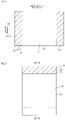
- the present invention [7] includes the reinforcing vibration-damping structure described in [6], wherein the object has a surface extending in a vertical direction, the reinforcement member is disposed on the surface of the object in the thickness direction orthogonal to the vertical direction, and the second portion protrudes upward beyond an upper edge of the reinforcement member in the vertical direction.
- Such a structure provides a simple structure in which the second portion can suppress the downward displacement of the reinforcement member.
- the present invention [8] includes the reinforcing vibration-damping structure described in [6], wherein the object has a surface extending in a vertical direction, the reinforcement member is disposed on the surface of the object in the thickness direction orthogonal to the vertical direction, and the second portion protrudes beyond an edge of the reinforcement member in a width direction orthogonal to both of the vertical direction and the thickness direction.
- Such a structure provides a simple structure in which the second portion can suppress the downward displacement of the reinforcement member.
- the present invention includes the reinforcing vibration-damping structure described in any one of the above-described [6] to [8], wherein the reinforcement member has a reinforcement layer disposed on the object in the thickness direction and a first constraining layer disposed on the reinforcement layer in the thickness direction, and the vibration-damping member has a vibration-damping layer disposed on the first constraining layer in the thickness direction and a second constraining layer disposed on the vibration-damping layer in the thickness direction.
- Such a structure enables the first constraining layer to give toughness to the reinforcement layer, and thus can improve the reinforcement performance.
- the structure enables the second constraining layer to give toughness to the vibration-damping layer and can also improve the vibration-damping performance.
- the present invention includes the reinforcing vibration-damping structure described in [9], wherein the reinforcement layer is a cured product of the first resin layer containing a thermosetting resin, and the vibration-damping layer is made of a second resin layer containing a butyl rubber.
- the present invention [11] includes the reinforcing vibration-damping structure described in [9] or [10], wherein the reinforcement layer is a foamed material.
- Such a structure can improve the reinforcement performance by increasing the thickness of the reinforcement layer.
- the reinforcing vibration-damping material and reinforcing vibration-damping structure of the present invention can improve both of the reinforcement performance and the vibration-damping performance and can suppress the downward displacement of the reinforcing vibration-damping material.
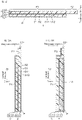
- a reinforcing vibration-damping material 1 illustrated in FIG. 1 is a material for reinforcing an object P (see FIG. 3B ) and damping the vibration of the object P.
- the reinforcement performance of the reinforcing vibration-damping material 1 can be evaluated using the bending strength of the object P to which the reinforcing vibration-damping material 1 is attached as described below in Examples.
- the bending strength is 30N or more according to the evaluation method described below, the reinforcing vibration-damping material 1 achieves reinforcement performance.
- the bending strength is preferably 40N or more.
- the "vibration-damping" means that to suppress the vibration of the object P.
- the vibration-damping performance can be evaluated using the loss factor of a second resonance point at 20°C of the object P to which the reinforcing vibration-damping material 1 is attached as described below in Examples.
- the loss factor of a second resonance point at 20°C is 0.1 or more according to the evaluation method described below, the reinforcing vibration-damping material 1 achieves vibration-damping performance.
- the loss factor of a second resonance point at 20°C is preferably 0.2 or more, more preferably 0.3 or more.
- the object P examples include metallic panels such as an aluminum plate, a stainless-steel plate, an iron plate, a copper plate, a zinc plate, and a brass plate.
- the metallic panel is used for, for example, transports such as automobiles, railway vehicles, vessels, and airplanes, or buildings.
- the reinforcing vibration-damping material 1 is a reinforcing vibration-damping sheet.
- the reinforcing vibration-damping material 1 includes a reinforcing material 2 and a vibration-damping material 3.
- the reinforcing vibration-damping material 1 includes a release sheet R (see the phantom line of FIG. 2 ).
- the reinforcing material 2 is a material for reinforcing the object P.
- the reinforcing material 2 has a sheet shape.
- the reinforcing material 2 includes a first resin layer 21 and a first constraining layer 22.
- the first resin layer 21 has a predetermined thickness in a thickness direction of the reinforcing material 2.
- the first resin layer 21 has a first surface S1 and a second surface S2 in the thickness direction.
- the first resin layer 21 has a thickness of, for example, 0.1 mm or more, preferably 0.2 mm or more, for example, 10 mm or less, preferably 5 mm or less.
- the first resin layer 21 consists of a first resin composition containing a thermosetting resin.
- the first resin composition preferably contains a diene rubber, a tackifier resin, a vulcanizing agent, a vulcanization accelerator, a thermosetting resin curing agent, a foaming agent, and a filler.
- the first resin composition may contain a known additive (such as a pigment or a thixotropic agent) in addition to the above-described components.
- thermosetting resin examples include epoxy resins.
- the epoxy resin examples include aromatic epoxy resins such as bisphenol epoxy resins (such as bisphenol A epoxy resin, bisphenol F epoxy resin, and bisphenol S epoxy resin), novolak epoxy resins (such as phenol novolak epoxy resin and cresol novolak epoxy resin), naphthalene epoxy resin and biphenyl epoxy resin, alicyclic epoxy resins such as dicyclo ring-type epoxy resin and hydrogenated bisphenol A epoxy resin, nitrogen-containing cyclic epoxy resins such as triglycidyl isocyanurate, hydantoin epoxy resin, and triepoxypropyl isocyanurate resin, and flexible epoxy resins such as aliphatic modified epoxy resin, butadiene epoxy resin, ⁇ -caprolactone-modified epoxy resin, thiol epoxy resin, rubber (such as NBR, carboxyl group-terminated NBR, or amino group-terminated NBR) -modified epoxy resin, dimer acid-modified epoxy resin, urethane-modified epoxy resin, polyol-modified
- epoxy resin preferably, a bisphenol epoxy resin and an alicyclic epoxy resin are used in combination, or a flexible epoxy resin is used alone.
- the content of the thermosetting resin in the first resin layer 21 is, for example, 10% by mass or more, preferably 20% by mass or more, more preferably 30% by mass or more, and, for example, 50% by mass or less, preferably 40% by mass or less.
- diene rubber examples include styrene-butadiene rubber (SBR), acrylonitrile-butadiene rubber (NBR), isoprene rubber, and butadiene rubber.
- diene rubber preferably, SBR is used alone, or NBR and butadiene rubber are used in combination.
- a blending ratio of the diene rubber is, for example, 10 parts by mass or more, preferably 20 parts by mass or more, more preferably 40 parts by mass or more, and, for example, 500 parts by mass or less, preferably 300 parts by mass or less, more preferably 100 parts by mass or less.
- the tackifier resin gives adhesion to the first resin layer 21.
- tackifier resin examples include natural resin-based tackifier resins and synthetic resin-based tackifier resins.
- Examples of the natural resin-based tackifier resin include rosin resins such as rosin esters, and terpene resins such as aromatic modified terpene resins and terpene phenol resins.
- Examples of the synthetic resin-based tackifier resin include aliphatic (C5) petroleum resins, aromatic (C9) petroleum resins, and aliphatic-aromatic copolymerized (C5/C9) petroleum resins.
- tackifier resin a synthetic resin-based tackifier resin is preferable, and an aliphatic-aromatic copolymerized petroleum resin is more preferable.
- a blending ratio of the tackifier resin is, for example, 20 parts by mass or more, preferably 40 parts by mass or more, and, for example, 80 parts by mass or less, preferably 70 parts by mass or less.
- a blending ratio of the tackifier resin is, for example, 50 parts by mass or more, preferably 80 parts by mass or more, and, for example, 200 parts by mass or less, preferably 150 parts by mass or less.
- the vulcanizing agent forms crosslinks of the diene rubber (or vulcanizes the diene rubber) by heating.
- Examples of the vulcanizing agent include sulfur, sulfur compounds, and organic peroxide.
- Sulfur is preferable as the vulcanizing agent.
- a blending ratio of the vulcanizing agent is, for example, 1 part by mass or more, preferably 5 parts by mass or more, more preferably 10 parts by mass or more, and, for example, 60 parts by mass or less, preferably 20 parts by mass or less.
- a blending ratio of the vulcanizing agent is, for example, 2 parts by mass or more, preferably 10 parts by mass or more, more preferably 20 parts by mass or more, and, for example, 90 parts by mass or less, preferably 70 parts by mass or less, more preferably 50 parts by mass or less.
- the vulcanization accelerator promotes the vulcanization of the vulcanizing agent.
- vulcanization accelerator examples include thiazole vulcanization accelerators, thiourea vulcanization accelerators, thiuram vulcanization accelerators, dithiocarbamate vulcanization accelerators, guanidine vulcanization accelerators, aldehyde-ammonia vulcanization accelerators, and sulfenamide vulcanization accelerators.
- a thiazole vulcanization accelerator is preferable.
- a blending ratio of the vulcanization accelerator is, for example, 1 part by mass or more, preferably 3 parts by mass or more, more preferably 5 parts by mass or more, and, for example, 20 parts by mass or less, preferably 10 parts by mass or less.
- a blending ratio of the vulcanization accelerator is, for example, 10 parts by mass or more, preferably 20 parts by mass or more, and, for example, 100 parts by mass or less, preferably 70 parts by mass or less.
- thermosetting resin curing agent promotes the curing of the thermosetting resin.
- thermosetting resin curing agent examples include cyanamide, amine, acid anhydride, amide, hydrazide, imidazole, and imidazoline.
- Examples of the cyanamide include dicyandiamide.
- amine examples include ethylenediamine, propylenediamine, diethylenetriamine, triethylenetetramine, and amine adduct thereof, methaphenylenediamine, diaminodiphenyl methane, and diaminodiphenyl sulfone.
- Examples of the acid anhydride include phthalic anhydride, maleic anhydride, tetrahydrophthalic anhydride, hexahydrophthalic anhydride, methyl nadic anhydride, pyromellitic acid anhydride, dodecenyl succinic anhydride, dichloro succinic anhydride, benzophenone tetracarboxylic anhydride, and chlorendic anhydride.
- amide examples include polyamide.
- Examples of the hydrazide include dihydrazide.
- imidazole examples include methylimidazole, 2-ethyl-4-methylimidazole, ethylimidazole, isopropylimidazole, 2,4-dimethylimidazole, phenylimidazole, undecylimidazole, heptadecylimidazole, and 2-phenyl-4-methylimidazole.
- imidazoline examples include methylimidazoline, 2-ethyl-4-methylimidazoline, ethylimidazoline, isopropylimidazoline, 2,4-dimethylimidazoline, phenylimidazoline, undecylimidazoline, heptadecylimidazoline, and 2-phenyl-4-methylimidazoline.
- thermosetting resin curing agent cyanamide is preferable.
- thermosetting resin curing agent To 100 parts by mass of the thermosetting resin, a blending ratio of the thermosetting resin curing agent is, for example, 1 part by mass or more, preferably 2 parts by mass or more, and, for example, 10 parts by mass or less, preferably 5 parts by mass or less.
- the foaming agent foams by heating.
- the first resin layer 21 containing the foaming agent can increase the thickness of the reinforcement layer 41 described below and improve the strength of the reinforcement member 4.
- foaming agent examples include inorganic foaming agents and organic foaming agents.
- Examples of the inorganic foaming agent include ammonium carbonate, ammonium hydrogen carbonate, sodium hydrogen carbonate, ammonium nitrite, sodium borohydride, and azides.
- organic foaming agent examples include N-nitroso compounds such as N,N'-dinitrosopentamethylenetetramine, azo compounds such as azobisisobutyronitrile, alkane fluorides such as trichloromonofluoromethane, hydrazine compounds such as 4,4'-oxybis (benzene sulfonyl hydrazide) and allylbis (sulfonyl hydrazide), semicarbazide compounds such as p-toluylenesulfonyl semicarbazide, and triazole compounds such as 5-morpholinyl-1, 2, 3, 4-thiatriazole.
- N-nitroso compounds such as N,N'-dinitrosopentamethylenetetramine
- azo compounds such as azobisisobutyronitrile
- alkane fluorides such as trichloromonofluoromethane
- hydrazine compounds such as 4,4'-oxybis (benzene
- an organic foaming agent is preferable, and 4,4'-oxybis (benzene sulfonyl hydrazide) is more preferable.
- a blending ratio of the foaming agent is, for example, 0.1 parts by mass or more, preferably 0.5 parts by mass or more, and, for example, 20 parts by mass or less, preferably 5 parts by mass or less.
- a blending ratio of the foaming agent is, for example, 0.2 parts by mass or more, preferably 1 part by mass or more, and, for example, 40 parts by mass or less, preferably 10 parts by mass or less.
- the filler examples include calcium carbonate such as heavy calcium carbonate and light calcium carbonate, carbon black such as acetylene black and furnace black, minerals such as talc, mica, clay, and bentonite, oxides such as silicon oxide (silica), aluminum oxide (alumina), and titanium oxide, silicates such as aluminum silicate, metals such as aluminum and iron, resins such as acrylic resin and styrene resin, hydroxides such as aluminum hydroxide and magnesium hydroxide, and nitrides such as boron nitride.
- calcium carbonate such as heavy calcium carbonate and light calcium carbonate
- carbon black such as acetylene black and furnace black
- minerals such as talc, mica, clay, and bentonite
- oxides such as silicon oxide (silica), aluminum oxide (alumina), and titanium oxide
- silicates such as aluminum silicate
- metals such as aluminum and iron
- resins such as acrylic resin and styrene resin
- hydroxides such as aluminum hydroxide and magnesium hydro
- filler preferably, calcium carbonate is used alone, or calcium carbonate and carbon black are used in combination, and, more preferably, heavy calcium carbonate is used alone, or heavy calcium carbonate and carbon black are used in combination.
- a blending ratio of the filler is, for example, 10 parts by mass or more, preferably 30 parts by mass or more, and, for example, 200 parts by mass or less, preferably 100 parts by mass or less, more preferably 70 parts by mass or less.
- the first constraining layer 22 is disposed on the second surface S2 of the first resin layer 21 in the thickness direction.
- the first constraining layer 22 constrains a reinforcement layer 41 described below (see FIG. 3B ).
- the first constraining layer 22 constrains the reinforcement layer 41, thereby improving the toughness of the reinforcement layer 41.
- the first constraining layer 22 has a predetermined thickness in the thickness direction.
- the first constraining layer 22 has a thickness of, for example, 0.01 mm or more, preferably 0.05 mm or more, and, for example, 3mm or less, preferably 1 mm or less.
- Examples of the material of the first constraining layer 22 include metals and glass fibers.
- Examples of the metals include aluminum and copper.
- As the metal aluminum is preferable.
- As the glass fiber a resin-impregnated fiberglass cloth is preferable.
- the vibration-damping material 3 as illustrated in FIG. 1 and FIG. 2 is a material for suppressing the vibration of the object P.
- the vibration-damping material 3 has a sheet shape.
- the vibration-damping material 3 is disposed on the reinforcing material 2 in the thickness direction.
- the vibration-damping material 3 is disposed on the first constraining layer 22 in the thickness direction.
- the vibration-damping material 3 is disposed on the opposite side to the first resin layer 21 with respect to the first constraining layer 22 in the thickness direction.
- the first portion P1 overlaps the reinforcing material 2 in the thickness direction.
- the first portion P1 is in contact with the reinforcing material 2.
- the first portion P1 is in contact with the first constraining layer 22.
- the second portion P2 does not overlap the reinforcing material 2 in the thickness direction. In the present embodiment, the second portion P2 protrudes beyond an edge of the reinforcing material 2 in a direction orthogonal to the thickness direction.
- the vibration-damping material 3 has a second resin layer 31 and a second constraining layer 32.
- the second resin layer 31 has a predetermined thickness in the thickness direction.
- the second resin layer 31 has a first surface S11 and a second surface S12 in the thickness direction.
- the second resin layer 31 has a thickness of, for example, 0.5 mm or more, and, for example, 6.0 mm or less, preferably 3.0 mm or less.
- the second resin layer 31 of the first portion P1 is disposed on the first constraining layer 22 in the thickness direction.
- the second resin layer 31 of the first portion P1 is in contact with the first constraining layer 22.
- the second resin layer 31 of the first portion P1 adheres to the first constraining layer 22 by the adhesion of the second resin layer 31.
- the second resin layer 31 consists of a second resin composition containing a butyl rubber.
- the content of the butyl rubber in the second resin layer 31 is, for example, 5% by mass or more, preferably 10% by mass or more, more preferably 20% by mass or more, and, for example, 50% by mass or less, preferably 30% by mass or less.
- the second resin composition preferably contains a softener, a tackifier resin, and a filler.
- the softener gives plasticity to the second resin layer 31.
- the softener examples include liquid rubbers such as polybutene, liquid isoprene rubber, and liquid butadiene rubber, oils such as paraffinic oil and naphthenic oil, and esters such as phthalate ester and phosphate ester.
- a liquid rubber is preferable, and polybutene is more preferable.
- a blending ratio of the softener is, for example, 30 parts by mass or more, preferably 40 parts by mass or more, more preferably 50 parts by mass or more, and, for example, 90 parts by mass or less, preferably 85 parts by mass or less, more preferably 80 parts by mass or less.
- the tackifier resin gives adhesion to the second resin layer 31, similarly to the above-described tackifier resin of the reinforcing material 2.
- tackifier resin examples include the same tackifier resins cited above as the tackifier resins of the reinforcing material 2.
- tackifier resin of the vibration-damping material 3 an aliphatic petroleum resin is preferable.
- a blending ratio of the tackifier resin is, for example, 5 parts by mass or more, preferably 10 parts by mass or more, more preferably 50 parts by mass or more, and, for example, 150 parts by mass or less, preferably 90 parts by mass or less.
- Examples of the filler include the same fillers cited above as the fillers of the reinforcing material 2.
- As the filler of the vibration-damping material 3 calcium carbonate and carbon black are preferable, and heavy calcium carbonate and carbon black are more preferable.
- a blending ratio of the filler is, for example, 100 parts by mass or more, preferably 150 parts by mass or more, more preferably 200 parts by mass or more, and, for example, 350 parts by mass or less, preferably 250 parts by mass or less.
- the second constraining layer 32 is disposed on the second surface S12 of the second resin layer 31 in the thickness direction.
- the second constraining layer 32 constrains a vibration-damping layer 51 described below (see FIG. 3B ).
- the second constraining layer 32 constrains the vibration-damping layer 51, thereby improving the toughness of the vibration-damping layer 51.
- the second constraining layer 32 has a predetermined thickness in the thickness direction.
- the second constraining layer 32 has a thickness of, for example, 0.05m m or more, preferably 0.1 mm or more, and, for example, 2.0 mm or less, preferably 1.0 mm or less.
- Examples of the material of the second constraining layer 32 include the same materials cited above as the materials of the first constraining layer 22.
- the release sheet R is disposed on the first surface S1 of the first resin layer 21 and on the first surface S11 of the second resin layer 31 of the second portion.
- the release sheet R protects the first resin layer 21 and the second resin layer 31 of the second portion while being disposed on the first surface S1 of the first resin layer 21 and on the first surface S11 of the second resin layer 31 of the second portion.
- the release sheet R can be released from the first resin layer 21 and the second resin layer 31 of the second portion.
- a known release paper is used as the release sheet R.
- the attachment method includes an adhering step (see FIG. 3A ), and a curing step for curing the first resin layer 21 and second resin layer 31 by heating while the reinforcing vibration-damping material 1 is attached to the object P (see FIG. 3B ).
- the object P has a surface S21 extending in a vertical direction.
- an operator makes the reinforcing vibration-damping material 1 adhere to the object P.
- the reinforcing vibration-damping material 1 is adhered to the object P so that the second portion P2 is disposed above the reinforcing material 2.
- the operator brings the first surface S1 of the first resin layer 21 into contact with the surface S21 of the object P, and brings the first surface S11 of the second resin layer 31 of the second portion P2 into contact with the surface S21 of the object P.
- the reinforcing vibration-damping material 1 adheres to the object P by the adhesive force of the first resin layer 21 and the adhesive force of the second resin layer 31.
- the thickness direction is orthogonal to the vertical direction.
- the operator heats the object P to which the reinforcing vibration-damping material 1 is adhered.
- the object P is heated at a heating temperature of, for example, 140°C or more, preferably 160°C or more, and, for example, 220°C or less, preferably 200°C or less.
- the object P is heated for a heating time of, for example, 5 minutes or more, preferably 10 minutes or more, and, for example, 60 minutes or less, preferably 30 minutes or less.
- the first resin layer 21 is softened by heating in the curing step.
- the softening of the first resin layer 21 and the weight of the vibration-damping material 3 may displace the reinforcing material 2 downward.
- the reinforcing material 2 is more likely to displace downward.
- the first portion P1 of the vibration-damping material 3 is adhered to the reinforcing material 2 and the second portion P2 of the vibration-damping material 3 is adhered to the object P.
- the vibration-damping material 3 holds the reinforcing material 2. This can suppress the downward displacement (heat drooping) of the reinforcing material 2.
- the reinforcing vibration-damping material 1 of the present embodiment can be maintained at a desired location.
- the amount of the downward displacement (the amount of heat drooping) of the reinforcing material 2 can be suppressed to, for example, less than 3 mm, preferably less than 2 mm.
- the reinforcement member 4 and vibration-damping member 5 are accurately disposed at the parts requiring reinforcement and vibration-damping, and thus both of the reinforcement performance and the vibration-damping performance can further be improved.
- the first resin layer 21 is cured.
- the first resin layer 21 contains a foaming agent
- the first resin layer 21 is foamed and cured.
- an expansion ratio (the thickness of the reinforcement layer 41/the thickness of the first resin layer 21) is, for example, twice or more, preferably 3 times or more, and, for example, 10 times or less.
- the curing of the first resin layer 21 forms the reinforcement layer 41.
- the reinforcement layer 41 is made of a cured product of the first resin layer 21.
- the reinforcement layer 41 is a foamed material.
- the curing of the first resin layer 21 of the reinforcing material 2 forms the reinforcement member 4 including the reinforcement layer 41 and the first constraining layer 22.
- the reinforcement member 4 is disposed on the surface S21 of the object P in the thickness direction and reinforces the object P.
- the reinforcement layer 41 is disposed on the surface S21 of the object P in the thickness direction.
- the reinforcement member 4 is fixed to the object P by the reinforcement layer 41.
- the first constraining layer 22 is disposed on the reinforcement layer 41 in the thickness direction.
- the vibration-damping material 3 becomes the vibration-damping member 5 without any change.
- the vibration-damping member 5 is disposed on a surface of the reinforcement member 4 in the thickness direction to suppress the vibration of the object P.
- the vibration-damping member 5 has the first portion P1 and the second portion P2.
- the second portion P2 is disposed on the surface S21 of the object P in the thickness direction.
- the second portion P2 protrudes upward beyond an upper edge of the reinforcement member 4 in the vertical direction.
- the vibration-damping member 5 includes the vibration-damping layer 51 and the second constraining layer 32.
- the vibration-damping layer 51 is made of the second resin layer 31.
- the vibration-damping layer 51 is disposed on the first constraining layer 22 in the thickness direction.
- the second constraining layer 32 is disposed on the vibration-damping layer 51 in the thickness direction.
- the reinforcing vibration-damping structure 10 including the object P, the reinforcement member 4, and the vibration-damping member 5 is formed as illustrated in FIG. 3B .
- the reinforcing material 2 reinforces the object P and, the vibration-damping material 3 can suppress the vibration of the object P.
- the reinforcing vibration-damping material 1 when the reinforcing vibration-damping material 1 is attached to the object P, the reinforcing material 2 is adhered to the object P and the second portion P2 of the vibration-damping material 3 can be adhered to the object P.
- the second portion P2 protrudes beyond an edge of the reinforcing material 2 in a direction orthogonal to the thickness direction.
- the second portion P2 of the vibration-damping material 3 can easily be adhered to the object P.
- the reinforcing material 2 includes the first resin layer 21 and the first constraining layer 22 disposed on the first resin layer 21, and the vibration-damping material 3 includes the second resin layer 31 disposed on the first constraining layer 22 and the second constraining layer 32 disposed on the second resin layer 31.
- first constraining layer 22 can constrain the first resin layer 21 and the second constraining layer 32 can constrain the second resin layer 31.
- the reinforcement member 4 is disposed on the object P, and the vibration-damping member 5 is disposed on the reinforcement member 4. This allows for the reinforcement of the object P with the reinforcement member 4 and the suppression of the vibration of the object P with the vibration-damping member 5.
- the reinforcement member 4 is disposed on the object P and the second portion P2 of the vibration-damping member 5 is disposed on the object P.
- the vibration-damping member 5 allows the reinforcement member 4 to be attached to the object P without the downward displacement. In this manner, the reinforcement member 4 and the vibration-damping member 5 can be maintained at desired locations.
- the reinforcement member 4 and the vibration-damping member 5 are accurately disposed at the parts of the object P that require reinforcement and vibration-damping, and thus both of the reinforcement performance and the vibration-damping performance can further be improved.
- the second portion P2 protrudes upward beyond the upper edge of the reinforcement member 4 in the vertical direction.
- the second portion P2 can suppress the downward displacement of the reinforcement member 4 in a simple structure.
- the reinforcement member 4 includes the reinforcement layer 41 disposed on the object P and the first constraining layer 22 disposed on the reinforcement layer 41
- the vibration-damping member 5 includes the vibration-damping layer 51 disposed on the first constraining layer 22 and the second constraining layer 32 disposed on the vibration-damping layer 51.
- the first constraining layer 22 can give toughness to the reinforcement layer 41 and improve the reinforcement performance.
- the second constraining layer 32 can give toughness to the vibration-damping layer 51 and can also improve the vibration-damping performance.
- the reinforcement layer 41 is a foamed material.
- the increased thickness of the reinforcement layer 41 can improve the reinforcement performance.
- the second portion P2 may be disposed at the whole of the periphery of the reinforcing material 2.
- the second portion P2 may be disposed at both sides in a width direction of the reinforcing material 2.
- the width direction is orthogonal to the vertical direction and the thickness direction. This variation demonstrates that the second portions P2 protrude beyond the edges of the reinforcement member 4 in the width direction while the first resin layer 21 is cured.
- This variation also provides a simple structure in which the second portion P2 can suppress the downward displacement of the reinforcement member 4.
- the vibration-damping material 3 may expose a part of the reinforcing material 2 to a degree that does not decrease the vibration-damping performance.
- the second portion P2 may be disposed at a lower side with respect to the reinforcing material 2.
- the second portion P2 may be disposed in a penetrating hole 100 formed in the reinforcing material 2.
- the reinforcing vibration-damping material 1 may not include the second constraining layer 32.
- the reinforcing vibration-damping material 1 may include the vibration-damping material 3 made of only the second resin layer 31.
- the shape of the reinforcing material 2 is not limited.
- the reinforcing material 2 may have, for example, an oval shape, a rectangular shape, and a wavy shape (including a rectangular shape having two wavy opposite sides).
- the shape of the vibration-damping material 3 is not limited.
- the reinforcing material 2 may also have, for example, an oval shape, a rectangular shape, and a wavy shape (including a rectangular shape having two wavy opposite sides).
- the shape of the vibration-damping material 3 may differ from that of the reinforcing material 2.
- the second portion P2 may not form a side of the vibration-damping material 3.
- the second portion P2 may protrude from a part of a side of the vibration-damping material 3.
- the protruding second portion P2 has a smaller width than that of the vibration-damping material 3.
- each second portion P2 may protrude from each of the upper side and lower side of the vibration-damping material 3. Alternatively, each second portion P2 may protrude from each of the one side and the other side in the width direction of the vibration-damping material 3. Alternatively, two or more second portions P2 may protrude from a side of the vibration-damping material 3.
- the above-described materials (1) to (8) of the first resin layer were mixed, thereby preparing a first resin composition.
- the prepared first resin composition was extended to a thickness of 1.0 mm by application of pressure by a mold press machine, thereby producing a first resin layer.
- a resin-impregnated glass cloth with a thickness of 0.2 mm was adhered as a first constraining layer to a one-side surface of the produced first resin layer. In this manner, a reinforcing material was produced.
- the prepared second resin composition was extended to a thickness of 2.0 mm by application of pressure by a mold press machine, thereby producing a second resin layer.
- a resin-impregnated glass cloth with a thickness of 0.2 mm was adhered as a second constraining layer to a one-side surface of the produced second resin layer. In this manner, a vibration-damping material was produced.
- the vibration-damping material was adhered to the first constraining layer of the reinforcing material.
- a reinforcing vibration-damping material was produced in the same manner as Example 1 except that the vibration-damping material was adhered to the first constraining layer of the reinforcing material as illustrated in FIG. 7 .
- a reinforcing vibration-damping material was produced in the same manner as Example 1 except that the vibration-damping material was adhered to the first constraining layer of the reinforcing material as illustrated in FIG. 6 .
- a reinforcing vibration-damping material was produced in the same manner as Example 1 except that the vibration-damping material was adhered to the first constraining layer of the reinforcing material as illustrated in FIG. 5 .
- a reinforcing vibration-damping material was produced in the same manner as Example 1 except that the vibration-damping material was adhered to the first constraining layer of the reinforcing material as illustrated in FIG. 9 .
- a reinforcing vibration-damping material was produced in the same manner as Example 1 except that a vibration-damping material in the same size as the reinforcing material was adhered to the first constraining layer of the reinforcing material so that the vibration-damping material does not protrude beyond the reinforcing material.
- the reinforcing vibration-damping material produced in each of Examples and Comparative Examples was adhered to a (thin) test steel plate with a thickness of 0.8 mm, a width of 10 mm, and a length of 250 mm.
- test steel plate was disposed to extend along the vertical direction and was heated at 180°C for 20 minutes.
- the first resin layer of the reinforcing material is foamed and cured, thereby producing a test piece (see FIG. 3B ). Then, the amount of downward displacement (heat drooping amount) of the reinforcing material at the heating was measured. Tables 1 and 2 show the results.
- the reinforcement performance of the produced test piece was evaluated using a tensile and compression testing machine Technograph TG-5KN (manufactured by MinebeaMitsumi Inc.).
- the testing machine supported the test piece at an interval of 100 mm in a state in which the test steel plate was on top. Then, the test bar was dropped from above to the longitudinal center of the test piece at a speed of 1 mm/min.
- Example 1 Example 2
- Example 3 Example 4
- Example 5 Thickness of reinforcing material (mm) 1.2 1.2 1.2 1.2 1.2 Thickness of vibration-damping material (mm) 2.2 2.2 2.2 2.2 2.2 Total thickness (mm) 3.4 3.4 3.4 3.4 3.4 3.4 3.4 Amount of heat drooping (mm) ⁇ 2.0 ⁇ 2.0 ⁇ 2.0 ⁇ 2.0 2.52 Bending strength (N) 43 43 43 43 43 43 43 Loss factor 0.31 0.31 0.31 0.31 [Table 2] Comparative Example 1 Comparative Example 2 Comparative Example 3 Thickness of reinforcing material (mm) 1.2 1.2 Thickness of vibration-damping material (mm) 2.2 2.2 Total thickness (mm) 1.2 2.2 3.4 Amount of heat drooping (mm) ⁇ 2.0 ⁇ 2.0 3.2 Bending strength (N) 43 9 43
- the reinforcing vibration-damping material and reinforcing vibration-damping structure of the present invention are used for reinforcing and damping the metal panels used for, for example, transports such as automobiles, railway vehicles, vessels, and airplanes, or buildings.
Landscapes
- Engineering & Computer Science (AREA)
- General Engineering & Computer Science (AREA)
- Mechanical Engineering (AREA)
- Architecture (AREA)
- Laminated Bodies (AREA)
- Vibration Prevention Devices (AREA)
Abstract
Description
- The present invention relates to a reinforcing vibration-damping material and a reinforcing vibration-damping structure.
- A vibration-damping reinforcing sheet, which includes a vibration-damping reinforcement layer containing a butyl rubber, an acrylonitrile-butadiene rubber, an epoxy resin, and an epoxy resin curing agent, has been proposed (for example, see
Patent document 1 below). - Patent Document 1:
Japanese Unexamined Patent Publication No. 2009-161659 - Such a vibration-damping reinforcing material as described in
Patent Document 1 may not sufficiently achieve reinforcement performance and vibration-damping performance. - In light of the foregoing, the present invention aims to provide a reinforcing vibration-damping material and a reinforcing vibration-damping structure, both of which can improve both of the reinforcement performance and vibration-damping performance and can suppress the downward displacement of the reinforcing vibration-damping material.
- The present invention [1] includes a reinforcing vibration-damping material comprising: a reinforcing material; and a vibration-damping material disposed on the reinforcing material in a thickness direction of the reinforcing material, wherein the vibration-damping material has a first portion that overlaps the reinforcing material in the thickness direction, and a second portion that does not overlap the reinforcing material in the thickness direction.
- Such a structure allows for the suppression of the vibration of the object with the vibration-damping material and the reinforcement of the object with the reinforcing material reinforces.
- Thus, both of the reinforcement performance and vibration-damping performance can be improved.
- When the reinforcing vibration-damping material is attached to the object, the reinforcing material is adhered to the object and simultaneously the second portion of the vibration-damping material can also be adhered to the object.
- Thus, the vibration-damping material can suppress the downward displacement of the reinforcing material.
- As a result, the downward displacement of the reinforcing vibration-damping material is suppressed and consequently the reinforcing vibration-damping material can be maintained at a desired location.
- The present invention [2] includes the reinforcing vibration-damping material described in [1], wherein the second portion protrudes beyond an edge of the reinforcing material in a direction orthogonal to the thickness direction.
- Such a structure facilitates the adherence of the second portion of the vibration-damping material to the object.
- The present invention [3] includes the reinforcing vibration-damping material described in [1] or [2], wherein the reinforcing material has a first resin layer and a first constraining layer disposed on the first resin layer in the thickness direction, and the vibration-damping material has a second resin layer disposed on the first constraining layer in the thickness direction and a second constraining layer disposed on the second resin layer in the thickness direction.
- By such a structure, the first constraining layer can constrain the first resin layer and the second constraining layer can constrain the second resin layer.
- These constraints can improve the handleability of the reinforcing vibration-damping material by maintaining the shapes of the first resin layer and second resin layer.
- The present invention [4] includes the reinforcing vibration-damping material described in [3], wherein the first resin layer contains a thermosetting resin, and the second resin layer contains a butyl rubber.
- The present invention [5] includes the reinforcing vibration-damping material described in [3] or [4], wherein the first resin layer further contains a foaming agent.
- The present invention [6] includes a reinforcing vibration-damping structure comprising: an object; a reinforcement member disposed on the object and reinforcing the object; and a vibration-damping member disposed on the reinforcement member in a thickness direction of the reinforcement member to suppress vibration of the object, wherein the vibration-damping member has a first portion that overlaps the reinforcement member in the thickness direction and a second portion that does not overlap the reinforcement member in the thickness direction and is disposed on the object in the thickness direction.
- Such a structure includes the reinforcement member disposed on the object and the vibration-damping member disposed on the reinforcement member, and thus can suppress the vibration of the object with the vibration-damping member while reinforcing the object with the reinforcement member.
- As a result, both of the reinforcement performance and the vibration-damping performance can be improved.
- Further, the reinforcement member is disposed on the object and the second portion of the vibration-damping member is also disposed on the object.
- Thus, the reinforcement member is attached to the object while the vibration-damping member suppresses the downward displacement of the reinforcement member. This can maintain the reinforcement member and the vibration-damping member at desired locations.
- As a result, the reinforcement member and the vibration-damping member are accurately disposed at parts of the object that require reinforcement and vibration-damping. Consequently, both of the reinforcement performance and the vibration-damping performance can further be improved.
- The present invention [7] includes the reinforcing vibration-damping structure described in [6], wherein the object has a surface extending in a vertical direction, the reinforcement member is disposed on the surface of the object in the thickness direction orthogonal to the vertical direction, and the second portion protrudes upward beyond an upper edge of the reinforcement member in the vertical direction.
- Such a structure provides a simple structure in which the second portion can suppress the downward displacement of the reinforcement member.
- The present invention [8] includes the reinforcing vibration-damping structure described in [6], wherein the object has a surface extending in a vertical direction, the reinforcement member is disposed on the surface of the object in the thickness direction orthogonal to the vertical direction, and the second portion protrudes beyond an edge of the reinforcement member in a width direction orthogonal to both of the vertical direction and the thickness direction.
- Such a structure provides a simple structure in which the second portion can suppress the downward displacement of the reinforcement member.
- The present invention [9] includes the reinforcing vibration-damping structure described in any one of the above-described [6] to [8], wherein the reinforcement member has a reinforcement layer disposed on the object in the thickness direction and a first constraining layer disposed on the reinforcement layer in the thickness direction, and the vibration-damping member has a vibration-damping layer disposed on the first constraining layer in the thickness direction and a second constraining layer disposed on the vibration-damping layer in the thickness direction.
- Such a structure enables the first constraining layer to give toughness to the reinforcement layer, and thus can improve the reinforcement performance.
- Further, the structure enables the second constraining layer to give toughness to the vibration-damping layer and can also improve the vibration-damping performance.
- The present invention [10] includes the reinforcing vibration-damping structure described in [9], wherein the reinforcement layer is a cured product of the first resin layer containing a thermosetting resin, and the vibration-damping layer is made of a second resin layer containing a butyl rubber.
- The present invention [11] includes the reinforcing vibration-damping structure described in [9] or [10], wherein the reinforcement layer is a foamed material.
- Such a structure can improve the reinforcement performance by increasing the thickness of the reinforcement layer.
- The reinforcing vibration-damping material and reinforcing vibration-damping structure of the present invention can improve both of the reinforcement performance and the vibration-damping performance and can suppress the downward displacement of the reinforcing vibration-damping material.
-
-
FIG. 1 is a plan view of a reinforcing vibration-damping material as one embodiment of the present invention, viewed from a reinforcing material side. -
FIG. 2 is a cross-sectional view of the reinforcing vibration-damping material ofFIG. 1 , taken along line A-A. -
FIG. 3 is an explanation view illustrating a method for reinforcing the object and damping the vibration of the object with the reinforcing vibration-damping material ofFIG. 1 .FIG. 3A illustrates an adhering step for making the reinforcing vibration-damping material adhering to the object.FIG. 3B illustrates a curing step for foaming and curing the first resin layer by heating the object to which the reinforcing vibration-damping material adheres. -
FIG. 4 is an explanation view illustrating the first variation. -
FIG. 5 is an explanation view illustrating the second variation. -
FIG. 6 is an explanation view illustrating the third variation. -
FIG. 7 is an explanation view illustrating the fourth variation. -
FIG. 8 is a cross-sectional view taken along line B-B ofFIG. 7 . -
FIG. 9 is an explanation view illustrating the fifth variation. -
FIG. 10 is an explanation view illustrating the sixth variation. - A reinforcing vibration-
damping material 1 illustrated inFIG. 1 is a material for reinforcing an object P (seeFIG. 3B ) and damping the vibration of the object P. - The reinforcement performance of the reinforcing vibration-damping
material 1 can be evaluated using the bending strength of the object P to which the reinforcing vibration-dampingmaterial 1 is attached as described below in Examples. When the bending strength is 30N or more according to the evaluation method described below, the reinforcing vibration-dampingmaterial 1 achieves reinforcement performance. The bending strength is preferably 40N or more. - The "vibration-damping" means that to suppress the vibration of the object P. The vibration-damping performance can be evaluated using the loss factor of a second resonance point at 20°C of the object P to which the reinforcing vibration-damping
material 1 is attached as described below in Examples. When the loss factor of a second resonance point at 20°C is 0.1 or more according to the evaluation method described below, the reinforcing vibration-dampingmaterial 1 achieves vibration-damping performance. The loss factor of a second resonance point at 20°C is preferably 0.2 or more, more preferably 0.3 or more. - Examples of the object P include metallic panels such as an aluminum plate, a stainless-steel plate, an iron plate, a copper plate, a zinc plate, and a brass plate. The metallic panel is used for, for example, transports such as automobiles, railway vehicles, vessels, and airplanes, or buildings. Preferably, the reinforcing vibration-damping
material 1 is a reinforcing vibration-damping sheet. - As illustrated in
FIG. 1 andFIG. 2 , the reinforcing vibration-dampingmaterial 1 includes a reinforcingmaterial 2 and a vibration-dampingmaterial 3. The reinforcing vibration-dampingmaterial 1, as necessary, includes a release sheet R (see the phantom line ofFIG. 2 ). - The reinforcing
material 2 is a material for reinforcing the object P. The reinforcingmaterial 2 has a sheet shape. The reinforcingmaterial 2 includes afirst resin layer 21 and a first constraininglayer 22. - The
first resin layer 21 has a predetermined thickness in a thickness direction of the reinforcingmaterial 2. Thefirst resin layer 21 has a first surface S1 and a second surface S2 in the thickness direction. - The
first resin layer 21 has a thickness of, for example, 0.1 mm or more, preferably 0.2 mm or more, for example, 10 mm or less, preferably 5 mm or less. - The
first resin layer 21 consists of a first resin composition containing a thermosetting resin. In addition to the above-described component, the first resin composition preferably contains a diene rubber, a tackifier resin, a vulcanizing agent, a vulcanization accelerator, a thermosetting resin curing agent, a foaming agent, and a filler. The first resin composition may contain a known additive (such as a pigment or a thixotropic agent) in addition to the above-described components. - Examples of the thermosetting resin include epoxy resins.
- Examples of the epoxy resin include aromatic epoxy resins such as bisphenol epoxy resins (such as bisphenol A epoxy resin, bisphenol F epoxy resin, and bisphenol S epoxy resin), novolak epoxy resins (such as phenol novolak epoxy resin and cresol novolak epoxy resin), naphthalene epoxy resin and biphenyl epoxy resin, alicyclic epoxy resins such as dicyclo ring-type epoxy resin and hydrogenated bisphenol A epoxy resin, nitrogen-containing cyclic epoxy resins such as triglycidyl isocyanurate, hydantoin epoxy resin, and triepoxypropyl isocyanurate resin, and flexible epoxy resins such as aliphatic modified epoxy resin, butadiene epoxy resin, ε-caprolactone-modified epoxy resin, thiol epoxy resin, rubber (such as NBR, carboxyl group-terminated NBR, or amino group-terminated NBR) -modified epoxy resin, dimer acid-modified epoxy resin, urethane-modified epoxy resin, polyol-modified epoxy resin, and amine-modified epoxy resin. The epoxy resins may be used in combination of two or more.
- As the epoxy resin, preferably, a bisphenol epoxy resin and an alicyclic epoxy resin are used in combination, or a flexible epoxy resin is used alone.
- The content of the thermosetting resin in the first resin layer 21 (first resin composition) is, for example, 10% by mass or more, preferably 20% by mass or more, more preferably 30% by mass or more, and, for example, 50% by mass or less, preferably 40% by mass or less.
- Examples of the diene rubber include styrene-butadiene rubber (SBR), acrylonitrile-butadiene rubber (NBR), isoprene rubber, and butadiene rubber.
- As the diene rubber, preferably, SBR is used alone, or NBR and butadiene rubber are used in combination.
- To 100 parts by mass of the thermosetting resin, a blending ratio of the diene rubber is, for example, 10 parts by mass or more, preferably 20 parts by mass or more, more preferably 40 parts by mass or more, and, for example, 500 parts by mass or less, preferably 300 parts by mass or less, more preferably 100 parts by mass or less.
- The tackifier resin gives adhesion to the
first resin layer 21. - Examples of the tackifier resin include natural resin-based tackifier resins and synthetic resin-based tackifier resins.
- Examples of the natural resin-based tackifier resin include rosin resins such as rosin esters, and terpene resins such as aromatic modified terpene resins and terpene phenol resins.
- Examples of the synthetic resin-based tackifier resin include aliphatic (C5) petroleum resins, aromatic (C9) petroleum resins, and aliphatic-aromatic copolymerized (C5/C9) petroleum resins.
- As the tackifier resin, a synthetic resin-based tackifier resin is preferable, and an aliphatic-aromatic copolymerized petroleum resin is more preferable.
- To 100 parts by mass of the thermosetting resin, a blending ratio of the tackifier resin is, for example, 20 parts by mass or more, preferably 40 parts by mass or more, and, for example, 80 parts by mass or less, preferably 70 parts by mass or less.
- To 100 parts by mass of the diene rubber, a blending ratio of the tackifier resin is, for example, 50 parts by mass or more, preferably 80 parts by mass or more, and, for example, 200 parts by mass or less, preferably 150 parts by mass or less.
- The vulcanizing agent forms crosslinks of the diene rubber (or vulcanizes the diene rubber) by heating.
- Examples of the vulcanizing agent include sulfur, sulfur compounds, and organic peroxide.
- Sulfur is preferable as the vulcanizing agent.
- To 100 parts by mass of the thermosetting resin, a blending ratio of the vulcanizing agent is, for example, 1 part by mass or more, preferably 5 parts by mass or more, more preferably 10 parts by mass or more, and, for example, 60 parts by mass or less, preferably 20 parts by mass or less.
- To 100 parts by mass of the diene rubber, a blending ratio of the vulcanizing agent is, for example, 2 parts by mass or more, preferably 10 parts by mass or more, more preferably 20 parts by mass or more, and, for example, 90 parts by mass or less, preferably 70 parts by mass or less, more preferably 50 parts by mass or less.
- The vulcanization accelerator promotes the vulcanization of the vulcanizing agent.
- Examples of the vulcanization accelerator include thiazole vulcanization accelerators, thiourea vulcanization accelerators, thiuram vulcanization accelerators, dithiocarbamate vulcanization accelerators, guanidine vulcanization accelerators, aldehyde-ammonia vulcanization accelerators, and sulfenamide vulcanization accelerators.
- As the vulcanization accelerator, a thiazole vulcanization accelerator is preferable.
- To 100 parts by mass of the thermosetting resin, a blending ratio of the vulcanization accelerator is, for example, 1 part by mass or more, preferably 3 parts by mass or more, more preferably 5 parts by mass or more, and, for example, 20 parts by mass or less, preferably 10 parts by mass or less.
- To 100 parts by mass of the vulcanizing agent, a blending ratio of the vulcanization accelerator is, for example, 10 parts by mass or more, preferably 20 parts by mass or more, and, for example, 100 parts by mass or less, preferably 70 parts by mass or less.
- The thermosetting resin curing agent promotes the curing of the thermosetting resin.
- Examples of the thermosetting resin curing agent include cyanamide, amine, acid anhydride, amide, hydrazide, imidazole, and imidazoline.
- Examples of the cyanamide include dicyandiamide.
- Examples of the amine include ethylenediamine, propylenediamine, diethylenetriamine, triethylenetetramine, and amine adduct thereof, methaphenylenediamine, diaminodiphenyl methane, and diaminodiphenyl sulfone.
- Examples of the acid anhydride include phthalic anhydride, maleic anhydride, tetrahydrophthalic anhydride, hexahydrophthalic anhydride, methyl nadic anhydride, pyromellitic acid anhydride, dodecenyl succinic anhydride, dichloro succinic anhydride, benzophenone tetracarboxylic anhydride, and chlorendic anhydride.
- Examples of the amide include polyamide.
- Examples of the hydrazide include dihydrazide.
- Examples of the imidazole include methylimidazole, 2-ethyl-4-methylimidazole, ethylimidazole, isopropylimidazole, 2,4-dimethylimidazole, phenylimidazole, undecylimidazole, heptadecylimidazole, and 2-phenyl-4-methylimidazole.
- Examples of the imidazoline include methylimidazoline, 2-ethyl-4-methylimidazoline, ethylimidazoline, isopropylimidazoline, 2,4-dimethylimidazoline, phenylimidazoline, undecylimidazoline, heptadecylimidazoline, and 2-phenyl-4-methylimidazoline.
- As the thermosetting resin curing agent, cyanamide is preferable.
- To 100 parts by mass of the thermosetting resin, a blending ratio of the thermosetting resin curing agent is, for example, 1 part by mass or more, preferably 2 parts by mass or more, and, for example, 10 parts by mass or less, preferably 5 parts by mass or less.
- The foaming agent foams by heating. The
first resin layer 21 containing the foaming agent can increase the thickness of the reinforcement layer 41 described below and improve the strength of thereinforcement member 4. - Examples of the foaming agent include inorganic foaming agents and organic foaming agents.
- Examples of the inorganic foaming agent include ammonium carbonate, ammonium hydrogen carbonate, sodium hydrogen carbonate, ammonium nitrite, sodium borohydride, and azides.
- Examples of the organic foaming agent include N-nitroso compounds such as N,N'-dinitrosopentamethylenetetramine, azo compounds such as azobisisobutyronitrile, alkane fluorides such as trichloromonofluoromethane, hydrazine compounds such as 4,4'-oxybis (benzene sulfonyl hydrazide) and allylbis (sulfonyl hydrazide), semicarbazide compounds such as p-toluylenesulfonyl semicarbazide, and triazole compounds such as 5-morpholinyl-1, 2, 3, 4-thiatriazole.
- As the foaming agent, an organic foaming agent is preferable, and 4,4'-oxybis (benzene sulfonyl hydrazide) is more preferable.
- To 100 parts by mass of the thermosetting resin, a blending ratio of the foaming agent is, for example, 0.1 parts by mass or more, preferably 0.5 parts by mass or more, and, for example, 20 parts by mass or less, preferably 5 parts by mass or less.
- To 100 parts by mass of the total of the thermosetting resin, the diene rubber, and the tackifier resin, a blending ratio of the foaming agent is, for example, 0.2 parts by mass or more, preferably 1 part by mass or more, and, for example, 40 parts by mass or less, preferably 10 parts by mass or less.
- Examples of the filler include calcium carbonate such as heavy calcium carbonate and light calcium carbonate, carbon black such as acetylene black and furnace black, minerals such as talc, mica, clay, and bentonite, oxides such as silicon oxide (silica), aluminum oxide (alumina), and titanium oxide, silicates such as aluminum silicate, metals such as aluminum and iron, resins such as acrylic resin and styrene resin, hydroxides such as aluminum hydroxide and magnesium hydroxide, and nitrides such as boron nitride.
- As the filler, preferably, calcium carbonate is used alone, or calcium carbonate and carbon black are used in combination, and, more preferably, heavy calcium carbonate is used alone, or heavy calcium carbonate and carbon black are used in combination.
- To 100 parts by mass of the thermosetting resin, a blending ratio of the filler is, for example, 10 parts by mass or more, preferably 30 parts by mass or more, and, for example, 200 parts by mass or less, preferably 100 parts by mass or less, more preferably 70 parts by mass or less.
- The first constraining
layer 22 is disposed on the second surface S2 of thefirst resin layer 21 in the thickness direction. The first constraininglayer 22 constrains a reinforcement layer 41 described below (seeFIG. 3B ). The first constraininglayer 22 constrains the reinforcement layer 41, thereby improving the toughness of the reinforcement layer 41. The first constraininglayer 22 has a predetermined thickness in the thickness direction. - The first constraining
layer 22 has a thickness of, for example, 0.01 mm or more, preferably 0.05 mm or more, and, for example, 3mm or less, preferably 1 mm or less. - Examples of the material of the first constraining
layer 22 include metals and glass fibers. Examples of the metals include aluminum and copper. As the metal, aluminum is preferable. As the glass fiber, a resin-impregnated fiberglass cloth is preferable. - The vibration-damping
material 3 as illustrated inFIG. 1 andFIG. 2 is a material for suppressing the vibration of the object P. The vibration-dampingmaterial 3 has a sheet shape. The vibration-dampingmaterial 3 is disposed on the reinforcingmaterial 2 in the thickness direction. The vibration-dampingmaterial 3 is disposed on the first constraininglayer 22 in the thickness direction. The vibration-dampingmaterial 3 is disposed on the opposite side to thefirst resin layer 21 with respect to the first constraininglayer 22 in the thickness direction. - The first portion P1 overlaps the reinforcing
material 2 in the thickness direction. The first portion P1 is in contact with the reinforcingmaterial 2. The first portion P1 is in contact with the first constraininglayer 22. - The second portion P2 does not overlap the reinforcing
material 2 in the thickness direction. In the present embodiment, the second portion P2 protrudes beyond an edge of the reinforcingmaterial 2 in a direction orthogonal to the thickness direction. - The vibration-damping
material 3 has asecond resin layer 31 and a second constraininglayer 32. - The
second resin layer 31 has a predetermined thickness in the thickness direction. Thesecond resin layer 31 has a first surface S11 and a second surface S12 in the thickness direction. - The
second resin layer 31 has a thickness of, for example, 0.5 mm or more, and, for example, 6.0 mm or less, preferably 3.0 mm or less. - The
second resin layer 31 of the first portion P1 is disposed on the first constraininglayer 22 in the thickness direction. Thesecond resin layer 31 of the first portion P1 is in contact with the first constraininglayer 22. Thesecond resin layer 31 of the first portion P1 adheres to the first constraininglayer 22 by the adhesion of thesecond resin layer 31. - In detail, the
second resin layer 31 consists of a second resin composition containing a butyl rubber. - The content of the butyl rubber in the second resin layer 31 (second resin composition) is, for example, 5% by mass or more, preferably 10% by mass or more, more preferably 20% by mass or more, and, for example, 50% by mass or less, preferably 30% by mass or less.
- In addition to the above-described component, the second resin composition preferably contains a softener, a tackifier resin, and a filler.
- The softener gives plasticity to the
second resin layer 31. - Examples of the softener include liquid rubbers such as polybutene, liquid isoprene rubber, and liquid butadiene rubber, oils such as paraffinic oil and naphthenic oil, and esters such as phthalate ester and phosphate ester.
- As the softener, a liquid rubber is preferable, and polybutene is more preferable.
- To 100 parts by mass of the butyl rubber, a blending ratio of the softener is, for example, 30 parts by mass or more, preferably 40 parts by mass or more, more preferably 50 parts by mass or more, and, for example, 90 parts by mass or less, preferably 85 parts by mass or less, more preferably 80 parts by mass or less.
- The tackifier resin gives adhesion to the
second resin layer 31, similarly to the above-described tackifier resin of the reinforcingmaterial 2. - Examples of the tackifier resin include the same tackifier resins cited above as the tackifier resins of the reinforcing
material 2. As the tackifier resin of the vibration-dampingmaterial 3, an aliphatic petroleum resin is preferable. - To 100 parts by mass of the butyl rubber, a blending ratio of the tackifier resin is, for example, 5 parts by mass or more, preferably 10 parts by mass or more, more preferably 50 parts by mass or more, and, for example, 150 parts by mass or less, preferably 90 parts by mass or less.
- Examples of the filler include the same fillers cited above as the fillers of the reinforcing
material 2. As the filler of the vibration-dampingmaterial 3, calcium carbonate and carbon black are preferable, and heavy calcium carbonate and carbon black are more preferable. - To 100 parts by mass of the butyl rubber, a blending ratio of the filler is, for example, 100 parts by mass or more, preferably 150 parts by mass or more, more preferably 200 parts by mass or more, and, for example, 350 parts by mass or less, preferably 250 parts by mass or less.
- The second constraining
layer 32 is disposed on the second surface S12 of thesecond resin layer 31 in the thickness direction. The second constraininglayer 32 constrains a vibration-damping layer 51 described below (seeFIG. 3B ). The second constraininglayer 32 constrains the vibration-damping layer 51, thereby improving the toughness of the vibration-damping layer 51. The second constraininglayer 32 has a predetermined thickness in the thickness direction. - The second constraining
layer 32 has a thickness of, for example, 0.05m m or more, preferably 0.1 mm or more, and, for example, 2.0 mm or less, preferably 1.0 mm or less. - Examples of the material of the second constraining
layer 32 include the same materials cited above as the materials of the first constraininglayer 22. - The release sheet R is disposed on the first surface S1 of the
first resin layer 21 and on the first surface S11 of thesecond resin layer 31 of the second portion. The release sheet R protects thefirst resin layer 21 and thesecond resin layer 31 of the second portion while being disposed on the first surface S1 of thefirst resin layer 21 and on the first surface S11 of thesecond resin layer 31 of the second portion. The release sheet R can be released from thefirst resin layer 21 and thesecond resin layer 31 of the second portion. As the release sheet R, for example, a known release paper is used. - Next, a method for attaching the reinforcing vibration-damping
material 1 to the object P is described. - As illustrated in
FIG. 3A and FIG. 3B , the attachment method includes an adhering step (seeFIG. 3A ), and a curing step for curing thefirst resin layer 21 andsecond resin layer 31 by heating while the reinforcing vibration-dampingmaterial 1 is attached to the object P (seeFIG. 3B ). - As illustrated in
FIG. 3A , the object P has a surface S21 extending in a vertical direction. - In the adhering step, an operator makes the reinforcing vibration-damping
material 1 adhere to the object P. In detail, the reinforcing vibration-dampingmaterial 1 is adhered to the object P so that the second portion P2 is disposed above the reinforcingmaterial 2. The operator brings the first surface S1 of thefirst resin layer 21 into contact with the surface S21 of the object P, and brings the first surface S11 of thesecond resin layer 31 of the second portion P2 into contact with the surface S21 of the object P. - In this manner, the reinforcing vibration-damping
material 1 adheres to the object P by the adhesive force of thefirst resin layer 21 and the adhesive force of thesecond resin layer 31. In this state, the thickness direction is orthogonal to the vertical direction. - Next, in the curing step, the operator heats the object P to which the reinforcing vibration-damping
material 1 is adhered. - The object P is heated at a heating temperature of, for example, 140°C or more, preferably 160°C or more, and, for example, 220°C or less, preferably 200°C or less.
- The object P is heated for a heating time of, for example, 5 minutes or more, preferably 10 minutes or more, and, for example, 60 minutes or less, preferably 30 minutes or less.
- At the time, the
first resin layer 21 is softened by heating in the curing step. The softening of thefirst resin layer 21 and the weight of the vibration-dampingmaterial 3 may displace the reinforcingmaterial 2 downward. Especially, when thefirst resin layer 21 contains a foaming agent, the reinforcingmaterial 2 is more likely to displace downward. - However, in this embodiment, the first portion P1 of the vibration-damping
material 3 is adhered to the reinforcingmaterial 2 and the second portion P2 of the vibration-dampingmaterial 3 is adhered to the object P. Thus, while the reinforcing vibration-dampingmaterial 1 of the present embodiment is adhered to the object P, the vibration-dampingmaterial 3 holds the reinforcingmaterial 2. This can suppress the downward displacement (heat drooping) of the reinforcingmaterial 2. As a result, the reinforcing vibration-dampingmaterial 1 of the present embodiment can be maintained at a desired location. - Specifically, the amount of the downward displacement (the amount of heat drooping) of the reinforcing
material 2 can be suppressed to, for example, less than 3 mm, preferably less than 2 mm. When the heat drooping amount is less than the above-described upper limit, thereinforcement member 4 and vibration-dampingmember 5 are accurately disposed at the parts requiring reinforcement and vibration-damping, and thus both of the reinforcement performance and the vibration-damping performance can further be improved. - As illustrated in
FIG. 3A and FIG. 3B , thefirst resin layer 21 is cured. When thefirst resin layer 21 contains a foaming agent, thefirst resin layer 21 is foamed and cured. When thefirst resin layer 21 contains a foaming agent, an expansion ratio (the thickness of the reinforcement layer 41/the thickness of the first resin layer 21) is, for example, twice or more, preferably 3 times or more, and, for example, 10 times or less. - The curing of the
first resin layer 21 forms the reinforcement layer 41. In other words, the reinforcement layer 41 is made of a cured product of thefirst resin layer 21. When thefirst resin layer 21 contains a foaming agent, the reinforcement layer 41 is a foamed material. The curing of thefirst resin layer 21 of the reinforcingmaterial 2 forms thereinforcement member 4 including the reinforcement layer 41 and the first constraininglayer 22. Thereinforcement member 4 is disposed on the surface S21 of the object P in the thickness direction and reinforces the object P. The reinforcement layer 41 is disposed on the surface S21 of the object P in the thickness direction. Thereinforcement member 4 is fixed to the object P by the reinforcement layer 41. The first constraininglayer 22 is disposed on the reinforcement layer 41 in the thickness direction. - The vibration-damping
material 3 becomes the vibration-dampingmember 5 without any change. In other words, the vibration-dampingmember 5 is disposed on a surface of thereinforcement member 4 in the thickness direction to suppress the vibration of the object P. The vibration-dampingmember 5 has the first portion P1 and the second portion P2. The second portion P2 is disposed on the surface S21 of the object P in the thickness direction. The second portion P2 protrudes upward beyond an upper edge of thereinforcement member 4 in the vertical direction. The vibration-dampingmember 5 includes the vibration-damping layer 51 and the second constraininglayer 32. The vibration-damping layer 51 is made of thesecond resin layer 31. The vibration-damping layer 51 is disposed on the first constraininglayer 22 in the thickness direction. The second constraininglayer 32 is disposed on the vibration-damping layer 51 in the thickness direction. - By completing the curing step, the reinforcing vibration-damping
structure 10 including the object P, thereinforcement member 4, and the vibration-dampingmember 5 is formed as illustrated inFIG. 3B . -
- (1) The reinforcing vibration-damping
material 1 includes the reinforcingmaterial 2 and the vibration-dampingmaterial 3 as illustrated inFIG. 1 andFIG. 2 . - Thus, as illustrated in
FIG. 3A and FIG. 3B , the reinforcingmaterial 2 reinforces the object P and, the vibration-dampingmaterial 3 can suppress the vibration of the object P. - As a result, both of the reinforcement performance and the vibration-damping performance can be improved.
- As illustrated in
FIG. 3A , when the reinforcing vibration-dampingmaterial 1 is attached to the object P, the reinforcingmaterial 2 is adhered to the object P and the second portion P2 of the vibration-dampingmaterial 3 can be adhered to the object P. - Thus, the downward displacement of the reinforcing
material 2 is suppressed by the vibration-dampingmaterial 3. - As a result, the downward displacement of the reinforcing vibration-damping
material 1 is suppressed and thus the reinforcing vibration-dampingmaterial 1 can be maintained at a desired location. - (2) In the reinforcing vibration-damping
material 1, as illustrated inFIG. 2 , the second portion P2 protrudes beyond an edge of the reinforcingmaterial 2 in a direction orthogonal to the thickness direction. - Thus, as illustrated in
FIG. 3A , the second portion P2 of the vibration-dampingmaterial 3 can easily be adhered to the object P. - (3) In the reinforcing vibration-damping
material 1, as illustrated inFIG. 2 , the reinforcingmaterial 2 includes thefirst resin layer 21 and the first constraininglayer 22 disposed on thefirst resin layer 21, and the vibration-dampingmaterial 3 includes thesecond resin layer 31 disposed on the first constraininglayer 22 and the second constraininglayer 32 disposed on thesecond resin layer 31. - Thus, the first constraining
layer 22 can constrain thefirst resin layer 21 and the second constraininglayer 32 can constrain thesecond resin layer 31. - In this manner, the shapes of the
first resin layer 21 andsecond resin layer 31 are maintained, and the handleability of the reinforcing vibration-dampingmaterial 1 can be improved. - (4) In the reinforcing vibration-damping
structure 10, as illustrated inFIG. 3B , thereinforcement member 4 is disposed on the object P, and the vibration-dampingmember 5 is disposed on thereinforcement member 4. This allows for the reinforcement of the object P with thereinforcement member 4 and the suppression of the vibration of the object P with the vibration-dampingmember 5. - As a result, both of the reinforcement performance and the vibration-damping performance can be improved.
- The
reinforcement member 4 is disposed on the object P and the second portion P2 of the vibration-dampingmember 5 is disposed on the object P. - Thus, the vibration-damping
member 5 allows thereinforcement member 4 to be attached to the object P without the downward displacement. In this manner, thereinforcement member 4 and the vibration-dampingmember 5 can be maintained at desired locations. - As a result, the
reinforcement member 4 and the vibration-dampingmember 5 are accurately disposed at the parts of the object P that require reinforcement and vibration-damping, and thus both of the reinforcement performance and the vibration-damping performance can further be improved. - (5) In the reinforcing vibration-damping
structure 10, as illustrated inFIG. 3B , the second portion P2 protrudes upward beyond the upper edge of thereinforcement member 4 in the vertical direction. - Thus, the second portion P2 can suppress the downward displacement of the
reinforcement member 4 in a simple structure. - (6) In the reinforcing vibration-damping
structure 10, as illustrated inFIG. 3B , thereinforcement member 4 includes the reinforcement layer 41 disposed on the object P and the first constraininglayer 22 disposed on the reinforcement layer 41, and the vibration-dampingmember 5 includes the vibration-damping layer 51 disposed on the first constraininglayer 22 and the second constraininglayer 32 disposed on the vibration-damping layer 51. - Thus, the first constraining
layer 22 can give toughness to the reinforcement layer 41 and improve the reinforcement performance. - Further, the second constraining
layer 32 can give toughness to the vibration-damping layer 51 and can also improve the vibration-damping performance. - (7) In the reinforcing vibration-damping
structure 10, as illustrated inFIG. 3B , the reinforcement layer 41 is a foamed material. - Thus, the increased thickness of the reinforcement layer 41 can improve the reinforcement performance.
-
- (1) The location of the second portion P2 in relation to the reinforcing
material 2 is not limited. For example, the second portion P2 may be disposed at an upper side and a lower side of the reinforcingmaterial 2 as illustrated inFIG. 4 while the reinforcing vibration-dampingmaterial 1 is adhered to the surface S21 of the object P. - Alternatively, as illustrated in
FIG. 5 , the second portion P2 may be disposed at the whole of the periphery of the reinforcingmaterial 2. - Alternatively, as illustrated in
FIG. 6 , the second portion P2 may be disposed at both sides in a width direction of the reinforcingmaterial 2. The width direction is orthogonal to the vertical direction and the thickness direction. This variation demonstrates that the second portions P2 protrude beyond the edges of thereinforcement member 4 in the width direction while thefirst resin layer 21 is cured. - This variation also provides a simple structure in which the second portion P2 can suppress the downward displacement of the
reinforcement member 4. - As illustrated in
FIG. 7 andFIG. 8 , the vibration-dampingmaterial 3 may expose a part of the reinforcingmaterial 2 to a degree that does not decrease the vibration-damping performance. - As illustrated in
FIG. 9 , the second portion P2 may be disposed at a lower side with respect to the reinforcingmaterial 2. - As illustrated in
FIG. 10 , the second portion P2 may be disposed in a penetratinghole 100 formed in the reinforcingmaterial 2. - (2) The reinforcing vibration-damping
material 1 may not include the second constraininglayer 32. The reinforcing vibration-dampingmaterial 1 may include the vibration-dampingmaterial 3 made of only thesecond resin layer 31. - (3) The shape of the reinforcing
material 2 is not limited. The reinforcingmaterial 2 may have, for example, an oval shape, a rectangular shape, and a wavy shape (including a rectangular shape having two wavy opposite sides). Similarly, the shape of the vibration-dampingmaterial 3 is not limited. The reinforcingmaterial 2 may also have, for example, an oval shape, a rectangular shape, and a wavy shape (including a rectangular shape having two wavy opposite sides). The shape of the vibration-dampingmaterial 3 may differ from that of the reinforcingmaterial 2. - (4) The second portion P2 may not form a side of the vibration-damping
material 3. For example, the second portion P2 may protrude from a part of a side of the vibration-dampingmaterial 3. The protruding second portion P2 has a smaller width than that of the vibration-dampingmaterial 3. - More specifically, each second portion P2 may protrude from each of the upper side and lower side of the vibration-damping
material 3. Alternatively, each second portion P2 may protrude from each of the one side and the other side in the width direction of the vibration-dampingmaterial 3. Alternatively, two or more second portions P2 may protrude from a side of the vibration-dampingmaterial 3. - Next, the present invention is described with reference to Examples and Comparative Examples. The present invention is not limited to the following Examples. The specific numeral values used in the description below, such as physical property values and parameters, can be replaced with the corresponding physical property values and parameters in the above-described "DESCRIPTION OF THE EMBODIMENT", including the upper limit values (numeral values defined with "or less", and "less than") or the lower limit values (numeral values defined with "or more", and "more than").
-
- (1) Thermosetting Resin
- Bisphenol A type epoxy resin (an epoxy equivalent of 230 to 270 g/eq, manufactured by Mitsubishi Chemical Holdings Corporation, "jER 834") 50 parts by mass
- Hydrogenated bisphenol A type epoxy resin (an epoxy equivalent of 215 g/eq, manufactured by ADEKA CORPORATION, "EP-4080E") 10 parts by mass
- (2) Diene Rubber
Styrene-butadiene rubber (manufactured by Asahi Kasei Chemicals, "TUFDENE") 40 parts by mass - (3) Tackifier Resin
Aliphatic-aromatic copolymerized petroleum resin (manufactured by Tosoh Corporation, "Petrotack 90HM") 40 parts by mass - (4) Vulcanizing agent
Sulfur (manufactured by Tsurumi Chemical Industry Co., ltd., "GOLDEN FLOWER SULFUR POWDER") 35 parts by mass - (5) Vulcanization accelerator
Thiazole vulcanization accelerator (manufactured by OUCHI SHINKO CHEMICAL INDUSTRIAL CO.,LTD., "NOCCELER DM") 10 parts by mass - (6) Thermosetting resin curing agent
Dicyandiamide (manufactured by NIPPON CARBIDE INDUSTRIES CO.,INC.) 5 parts by mass - (7) Foaming agent
4,4'-oxybis (benzene sulfonyl hydrazide) (OBSH) (manufactured by EIWA CHEMICAL IND.CO.,LTD., "Neocellborn N#1000S") 2 parts by mass - (8) Filler
- Heavy calcium carbonate (manufactured by Maruo Calcium Co., Ltd.) 100 parts by mass
- Carbon black (manufactured by Asahi Carbon Co., Ltd., "Asahi #50") 3 parts by mass
-
- (1) Butyl Rubber
S butyl recycled rubber (manufactured by Agata Rubber Industry Co.,Ltd.) 100 parts by mass - (2) Softener
Liquid polybutene (manufactured by JX NIPPON OIL & ENERGY CORPORATION, "polybutene HV-15") 70 parts by mass - (3) Tackifier Resin
Aliphatic petroleum resin (manufactured by Exxon Mobil Corporation, "Escorez 1202") 70 parts by mass - (4) Filler
- Heavy calcium carbonate (manufactured by Maruo Calcium Co., Ltd.) 170 parts by mass
- Carbon black (manufactured by Asahi Carbon Co., Ltd., "Asahi #50") 50 parts by
mass 2. Production of Reinforcing Vibration-damping Material
- The above-described materials (1) to (8) of the first resin layer were mixed, thereby preparing a first resin composition. The prepared first resin composition was extended to a thickness of 1.0 mm by application of pressure by a mold press machine, thereby producing a first resin layer. A resin-impregnated glass cloth with a thickness of 0.2 mm was adhered as a first constraining layer to a one-side surface of the produced first resin layer. In this manner, a reinforcing material was produced.
- Next, the above-described materials (1) to (4) of the second resin layer were mixed, thereby preparing a second resin composition. The prepared second resin composition was extended to a thickness of 2.0 mm by application of pressure by a mold press machine, thereby producing a second resin layer. A resin-impregnated glass cloth with a thickness of 0.2 mm was adhered as a second constraining layer to a one-side surface of the produced second resin layer. In this manner, a vibration-damping material was produced.
- Next, as illustrated in
FIG. 1 andFIG. 2 , the vibration-damping material was adhered to the first constraining layer of the reinforcing material. - In this manner, a reinforcing vibration-damping material was produced.
- A reinforcing vibration-damping material was produced in the same manner as Example 1 except that the vibration-damping material was adhered to the first constraining layer of the reinforcing material as illustrated in
FIG. 7 . - A reinforcing vibration-damping material was produced in the same manner as Example 1 except that the vibration-damping material was adhered to the first constraining layer of the reinforcing material as illustrated in
FIG. 6 . - A reinforcing vibration-damping material was produced in the same manner as Example 1 except that the vibration-damping material was adhered to the first constraining layer of the reinforcing material as illustrated in
FIG. 5 . - A reinforcing vibration-damping material was produced in the same manner as Example 1 except that the vibration-damping material was adhered to the first constraining layer of the reinforcing material as illustrated in
FIG. 9 . - Only a reinforcing material was produced in the same manner as Example 1 without producing a vibration-damping material.
- Only a vibration-damping material was produced in the same manner as Example 1 without producing a reinforcing material.
- A reinforcing vibration-damping material was produced in the same manner as Example 1 except that a vibration-damping material in the same size as the reinforcing material was adhered to the first constraining layer of the reinforcing material so that the vibration-damping material does not protrude beyond the reinforcing material.
- The reinforcing vibration-damping material produced in each of Examples and Comparative Examples (the reinforcing material in Comparative Example 1, and the vibration-damping material in Comparative Example 2) was adhered to a (thin) test steel plate with a thickness of 0.8 mm, a width of 10 mm, and a length of 250 mm.
- Next, as illustrated in
FIG. 3A , the test steel plate was disposed to extend along the vertical direction and was heated at 180°C for 20 minutes. - In this manner, the first resin layer of the reinforcing material is foamed and cured, thereby producing a test piece (see
FIG. 3B ). Then, the amount of downward displacement (heat drooping amount) of the reinforcing material at the heating was measured. Tables 1 and 2 show the results. - The reinforcement performance of the produced test piece was evaluated using a tensile and compression testing machine Technograph TG-5KN (manufactured by MinebeaMitsumi Inc.).
- In detail, the testing machine supported the test piece at an interval of 100 mm in a state in which the test steel plate was on top. Then, the test bar was dropped from above to the longitudinal center of the test piece at a speed of 1 mm/min.
- The bending strength of a 1-mm displacement of the reinforcement layer after the contact of the test bar with the test steel plate was evaluated as the reinforcement performance. Tables 1 and 2 show the results.
- The loss factor of a second resonance point of the produced test piece at 20°C was measured by a central exciting method according to JIS K 7391. Tables 1 and 2 show the results.
[Table 1] Example 1 Example 2 Example 3 Example 4 Example 5 Thickness of reinforcing material (mm) 1.2 1.2 1.2 1.2 1.2 Thickness of vibration-damping material (mm) 2.2 2.2 2.2 2.2 2.2 Total thickness (mm) 3.4 3.4 3.4 3.4 3.4 Amount of heat drooping (mm) < 2.0 < 2.0 < 2.0 < 2.0 2.52 Bending strength (N) 43 43 43 43 43 Loss factor 0.31 0.31 0.31 0.31 0.31 [Table 2] Comparative Example 1 Comparative Example 2 Comparative Example 3 Thickness of reinforcing material (mm) 1.2 1.2 Thickness of vibration-damping material (mm) 2.2 2.2 Total thickness (mm) 1.2 2.2 3.4 Amount of heat drooping (mm) < 2.0 < 2.0 3.2 Bending strength (N) 43 9 43 Loss factor 0.02 0.30 0.31 - While the illustrative embodiments of the present invention are provided in the above description, such is for illustrative purpose only and it is not to be construed as limiting in any manner. Modification and variation of the present invention that will be obvious to those skilled in the art is to be covered by the following claims.
- The reinforcing vibration-damping material and reinforcing vibration-damping structure of the present invention are used for reinforcing and damping the metal panels used for, for example, transports such as automobiles, railway vehicles, vessels, and airplanes, or buildings.
-
- 1
- reinforcing vibration-damping material
- 2
- reinforcing material
- 3
- vibration-damping material
- 4
- reinforcement member
- 5
- vibration-damping member
- 21
- first resin layer
- 22
- first constraining layer
- 31
- second resin layer
- 32
- second constraining layer
- 41
- reinforcement layer
- 51
- vibration-damping layer
- P
- object
- P1
- first portion
- P2
- second portion
Claims (11)
- A reinforcing vibration-damping material comprising:a reinforcing material; anda vibration-damping material disposed on the reinforcing material in a thickness direction of the reinforcing material, whereinthe vibration-damping material has a first portion that overlaps the reinforcing material in the thickness direction, and a second portion that does not overlap the reinforcing material in the thickness direction.
- The reinforcing vibration-damping material according to claim 1, wherein the second portion protrudes beyond an edge of the reinforcing material in a direction orthogonal to the thickness direction.
- The reinforcing vibration-damping material according to claim 1, whereinthe reinforcing material has a first resin layer and a first constraining layer disposed on the first resin layer in the thickness direction, andthe vibration-damping material has a second resin layer disposed on the first constraining layer in the thickness direction and a second constraining layer disposed on the second resin layer in the thickness direction.
- The reinforcing vibration-damping material according to claim 3, whereinthe first resin layer contains a thermosetting resin, andthe second resin layer contains a butyl rubber.
- The reinforcing vibration-damping material according to claim 3, wherein
the first resin layer further contains a foaming agent. - A reinforcing vibration-damping structure comprising:an object;a reinforcement member disposed on the object and reinforcing the object; anda vibration-damping member disposed on the reinforcement member in a thickness direction of the reinforcement member to suppress vibration of the object, whereinthe vibration-damping member has a first portion that overlaps the reinforcement member in the thickness direction and a second portion that does not overlap the reinforcement member in the thickness direction and is disposed on the object in the thickness direction.
- The reinforcing vibration-damping structure according to claim 6, whereinthe object has a surface extending in a vertical direction,the reinforcement member is disposed on the surface of the object in the thickness direction orthogonal to the vertical direction, andthe second portion protrudes upward beyond an upper edge of the reinforcement member in the vertical direction.
- The reinforcing vibration-damping structure according to claim 6, whereinthe object has a surface extending in a vertical direction,the reinforcement member is disposed on the surface of the object in the thickness direction orthogonal to the vertical direction, andthe second portion protrudes beyond an edge of the reinforcement member in a width direction orthogonal to both of the vertical direction and the thickness direction.
- The reinforcing vibration-damping structure according to claim 6, whereinthe reinforcement member has a reinforcement layer disposed on the object in the thickness direction and a first constraining layer disposed on the reinforcement layer in the thickness direction, andthe vibration-damping member has a vibration-damping layer disposed on the first constraining layer in the thickness direction and a second constraining layer disposed on the vibration-damping layer in the thickness direction.
- The reinforcing vibration-damping structure according to claim 9, whereinthe reinforcement layer is a cured product of the first resin layer containing a thermosetting resin, andthe vibration-damping layer is made of a second resin layer containing a butyl rubber.
- The reinforcing vibration-damping structure according to claim 9, wherein
the reinforcement layer is a foamed material.
Applications Claiming Priority (2)
| Application Number | Priority Date | Filing Date | Title |
|---|---|---|---|
| JP2020003127A JP7291638B2 (en) | 2020-01-10 | 2020-01-10 | Compensating material and compensating structure |
| PCT/JP2020/038964 WO2021140719A1 (en) | 2020-01-10 | 2020-10-15 | Reinforcing vibration-damping material and reinforcing vibration-damping structure |
Publications (2)
| Publication Number | Publication Date |
|---|---|
| EP4088924A1 true EP4088924A1 (en) | 2022-11-16 |
| EP4088924A4 EP4088924A4 (en) | 2024-01-03 |
Family
ID=76788847
Family Applications (1)
| Application Number | Title | Priority Date | Filing Date |
|---|---|---|---|
| EP20912144.1A Pending EP4088924A4 (en) | 2020-01-10 | 2020-10-15 | Reinforcing vibration-damping material and reinforcing vibration-damping structure |
Country Status (5)
| Country | Link |
|---|---|
| US (1) | US12297888B2 (en) |
| EP (1) | EP4088924A4 (en) |
| JP (1) | JP7291638B2 (en) |
| CN (1) | CN114867949A (en) |
| WO (1) | WO2021140719A1 (en) |
Families Citing this family (3)
| Publication number | Priority date | Publication date | Assignee | Title |
|---|---|---|---|---|
| JP7291638B2 (en) * | 2020-01-10 | 2023-06-15 | 日東電工株式会社 | Compensating material and compensating structure |
| JP7362695B2 (en) | 2021-07-01 | 2023-10-17 | ムーン クリエイティブ ラボ インク. | Articles and their manufacturing methods |
| JPWO2024232184A1 (en) * | 2023-05-09 | 2024-11-14 |
Family Cites Families (28)
| Publication number | Priority date | Publication date | Assignee | Title |
|---|---|---|---|---|
| US3160549A (en) | 1960-12-29 | 1964-12-08 | Minnesota Mining & Mfg | Vibration damping structures |
| GB1220076A (en) * | 1967-05-18 | 1971-01-20 | Solarbridge Engineering Ltd | Improvements in and relating to resilient bearings |
| DE2345990A1 (en) * | 1970-04-15 | 1975-04-03 | Raoul Dipl Ing Joern | SPRING ELEMENT, IN PARTICULAR FOR THE ELASTIC MOUNTING OF MOTORS |
| JPS5968605U (en) * | 1982-10-29 | 1984-05-09 | 日本鋼管株式会社 | Composite steel plate for vibration damping |
| US5232073A (en) * | 1988-12-09 | 1993-08-03 | Trw Inc. | Process for damping dynamic load |
| JPH06213274A (en) * | 1993-01-18 | 1994-08-02 | Yokohama Rubber Co Ltd:The | Execution method for damping construction of object to be mounted |
| JPH06246878A (en) * | 1993-02-26 | 1994-09-06 | Nippon Zeon Co Ltd | Vehicular vibration damping structural body |
| JPH07139584A (en) * | 1993-11-16 | 1995-05-30 | Nitto Denko Corp | Damping material |
| JPH07137208A (en) * | 1993-11-18 | 1995-05-30 | Nitto Denko Corp | Adhesive sheet for thin plate reinforcement |
| US5507477A (en) * | 1994-07-28 | 1996-04-16 | Trw Inc. | Composite damping structures and related method |
| TW295612B (en) * | 1995-07-21 | 1997-01-11 | Minnesota Mining & Mfg | |
| US5705769A (en) * | 1996-05-14 | 1998-01-06 | The United States Of America As Represented By The Secretary Of The Navy | Vibrationally damped structure |
| JP3012206B2 (en) * | 1996-10-28 | 2000-02-21 | 早川ゴム株式会社 | Vibration and soundproof structure |
| JP2006341821A (en) * | 2005-06-10 | 2006-12-21 | Iida Sangyo Kk | Steel plate reinforcement material |
| JP2007160895A (en) * | 2005-12-16 | 2007-06-28 | Iida Sangyo Kk | Vibration control reinforcement for metal sheet |
| JP5022838B2 (en) | 2007-09-10 | 2012-09-12 | 日東電工株式会社 | Damping and reinforcing sheet and method for damping and reinforcing thin plate |
| JP5415698B2 (en) * | 2008-01-07 | 2014-02-12 | 日東電工株式会社 | Damping and reinforcing sheet and method for damping and reinforcing thin plate |
| JP2011089547A (en) | 2009-10-20 | 2011-05-06 | Nitto Denko Corp | Vibration damping sheet, method for damping vibration of vibrating member and method of using the member |
| JP2012056112A (en) * | 2010-09-06 | 2012-03-22 | Nitto Denko Corp | Reinforcing sheet and reinforcing method |
| JP2015205451A (en) * | 2014-04-21 | 2015-11-19 | 株式会社大和 | Panel structure and energy damping interior and exterior material |
| US9527370B2 (en) | 2014-06-26 | 2016-12-27 | Ford Global Technologies, Llc | Damping and stiffening of a vehicle body panel |
| JP6360766B2 (en) * | 2014-09-30 | 2018-07-18 | 積水化成品工業株式会社 | Damping structure and damping material |
| JP2016074803A (en) * | 2014-10-06 | 2016-05-12 | 日東電工株式会社 | Pasting material, reinforcement member and manufacturing method thereof |
| CN106085294B (en) | 2016-07-19 | 2018-06-12 | 柳州市兴拓工贸有限责任公司 | Automobile multifunctional damping film and preparation method thereof |
| CN107603406A (en) * | 2017-09-18 | 2018-01-19 | 河北清华发展研究院 | A kind of lightweight constrained layer material and its application method for constrained damping structure |
| US20200271184A1 (en) * | 2017-11-13 | 2020-08-27 | Avery Dennison Corporation | Vibration Reduction Sheet and Method of Reducing Vibration |
| KR102717989B1 (en) * | 2018-05-17 | 2024-10-16 | 애버리 데니슨 코포레이션 | Partial Coverage Multilayer Damping Laminate |
| JP7291638B2 (en) * | 2020-01-10 | 2023-06-15 | 日東電工株式会社 | Compensating material and compensating structure |
-
2020
- 2020-01-10 JP JP2020003127A patent/JP7291638B2/en active Active
- 2020-10-15 EP EP20912144.1A patent/EP4088924A4/en active Pending
- 2020-10-15 CN CN202080090352.4A patent/CN114867949A/en active Pending
- 2020-10-15 WO PCT/JP2020/038964 patent/WO2021140719A1/en not_active Ceased
- 2020-10-15 US US17/791,414 patent/US12297888B2/en active Active
Also Published As
| Publication number | Publication date |
|---|---|
| WO2021140719A1 (en) | 2021-07-15 |
| JP2021110402A (en) | 2021-08-02 |
| JP7291638B2 (en) | 2023-06-15 |
| CN114867949A (en) | 2022-08-05 |
| EP4088924A4 (en) | 2024-01-03 |
| US20230062802A1 (en) | 2023-03-02 |
| US12297888B2 (en) | 2025-05-13 |
Similar Documents
| Publication | Publication Date | Title |
|---|---|---|
| US8298673B2 (en) | Vibration-damping reinforcement composition, vibration-damping reinforcement material, and method for vibration damping and reinforcement of thin sheet | |
| US7875344B2 (en) | Steel-plate-reinforcement resin composition, steel plate reinforcing sheet, and reinforcing method of steel plate | |
| EP1504890B1 (en) | Adhesive sheet for steel plate | |
| EP4088924A1 (en) | Reinforcing vibration-damping material and reinforcing vibration-damping structure | |
| EP2012295A1 (en) | Reinforcing sheet for image display, image display, and method for reinforcing the same | |
| JP3708934B2 (en) | Adhesive sheet for steel plate | |
| JP5604115B2 (en) | Reinforcing material for outer plate and method for reinforcing outer plate | |
| CN100540291C (en) | Reinforcing sheet for steel sheet | |
| CN100560361C (en) | Steel plate reinforcing sheet | |
| JP5295509B2 (en) | Reinforcing sheet for image display device, image display device and method for reinforcing the same | |
| WO2012032924A1 (en) | Reinforcing sheet and reinforcing method | |
| CN113330080B (en) | Single layer self-adhesive reinforced patch | |
| JP2005041210A (en) | Steel sheet reinforcement sheet | |
| US12297643B2 (en) | Reinforcing material and reinforcing structure | |
| EP3892456A1 (en) | Reinforcing sheet and reinforcing structure | |
| JP7174608B2 (en) | Reinforcement sheet and reinforcement structure | |
| CN101579954A (en) | Reinforcing sheet for steel plate | |
| US20240158672A1 (en) | Reinforcement material and reinforcement structure |
Legal Events
| Date | Code | Title | Description |
|---|---|---|---|
| STAA | Information on the status of an ep patent application or granted ep patent |
Free format text: STATUS: THE INTERNATIONAL PUBLICATION HAS BEEN MADE |
|
| PUAI | Public reference made under article 153(3) epc to a published international application that has entered the european phase |
Free format text: ORIGINAL CODE: 0009012 |
|
| STAA | Information on the status of an ep patent application or granted ep patent |
Free format text: STATUS: REQUEST FOR EXAMINATION WAS MADE |
|
| 17P | Request for examination filed |
Effective date: 20220629 |
|
| AK | Designated contracting states |
Kind code of ref document: A1 Designated state(s): AL AT BE BG CH CY CZ DE DK EE ES FI FR GB GR HR HU IE IS IT LI LT LU LV MC MK MT NL NO PL PT RO RS SE SI SK SM TR |
|
| DAV | Request for validation of the european patent (deleted) | ||
| DAX | Request for extension of the european patent (deleted) | ||
| REG | Reference to a national code |
Ref country code: DE Ref legal event code: R079 Free format text: PREVIOUS MAIN CLASS: B32B0025140000 Ipc: B32B0003040000 |
|
| A4 | Supplementary search report drawn up and despatched |
Effective date: 20231201 |
|
| RIC1 | Information provided on ipc code assigned before grant |
Ipc: F16F 1/40 20060101ALI20231128BHEP Ipc: B32B 33/00 20060101ALI20231128BHEP Ipc: B32B 27/06 20060101ALI20231128BHEP Ipc: B32B 25/18 20060101ALI20231128BHEP Ipc: B32B 25/04 20060101ALI20231128BHEP Ipc: B32B 3/26 20060101ALI20231128BHEP Ipc: B32B 3/08 20060101ALI20231128BHEP Ipc: B32B 3/04 20060101AFI20231128BHEP |