EP4088825A1 - Dispensing nozzle clamp - Google Patents
Dispensing nozzle clamp Download PDFInfo
- Publication number
- EP4088825A1 EP4088825A1 EP22169679.2A EP22169679A EP4088825A1 EP 4088825 A1 EP4088825 A1 EP 4088825A1 EP 22169679 A EP22169679 A EP 22169679A EP 4088825 A1 EP4088825 A1 EP 4088825A1
- Authority
- EP
- European Patent Office
- Prior art keywords
- nozzle
- arm
- protrusion
- bore
- fastener
- Prior art date
- Legal status (The legal status is an assumption and is not a legal conclusion. Google has not performed a legal analysis and makes no representation as to the accuracy of the status listed.)
- Pending
Links
Images




Classifications
-
- B—PERFORMING OPERATIONS; TRANSPORTING
- B05—SPRAYING OR ATOMISING IN GENERAL; APPLYING FLUENT MATERIALS TO SURFACES, IN GENERAL
- B05B—SPRAYING APPARATUS; ATOMISING APPARATUS; NOZZLES
- B05B15/00—Details of spraying plant or spraying apparatus not otherwise provided for; Accessories
- B05B15/60—Arrangements for mounting, supporting or holding spraying apparatus
- B05B15/62—Arrangements for supporting spraying apparatus, e.g. suction cups
-
- B—PERFORMING OPERATIONS; TRANSPORTING
- B05—SPRAYING OR ATOMISING IN GENERAL; APPLYING FLUENT MATERIALS TO SURFACES, IN GENERAL
- B05C—APPARATUS FOR APPLYING FLUENT MATERIALS TO SURFACES, IN GENERAL
- B05C5/00—Apparatus in which liquid or other fluent material is projected, poured or allowed to flow on to the surface of the work
- B05C5/02—Apparatus in which liquid or other fluent material is projected, poured or allowed to flow on to the surface of the work the liquid or other fluent material being discharged through an outlet orifice by pressure, e.g. from an outlet device in contact or almost in contact, with the work
- B05C5/027—Coating heads with several outlets, e.g. aligned transversally to the moving direction of a web to be coated
-
- B—PERFORMING OPERATIONS; TRANSPORTING
- B05—SPRAYING OR ATOMISING IN GENERAL; APPLYING FLUENT MATERIALS TO SURFACES, IN GENERAL
- B05B—SPRAYING APPARATUS; ATOMISING APPARATUS; NOZZLES
- B05B15/00—Details of spraying plant or spraying apparatus not otherwise provided for; Accessories
- B05B15/60—Arrangements for mounting, supporting or holding spraying apparatus
- B05B15/65—Mounting arrangements for fluid connection of the spraying apparatus or its outlets to flow conduits
- B05B15/652—Mounting arrangements for fluid connection of the spraying apparatus or its outlets to flow conduits whereby the jet can be oriented
-
- B—PERFORMING OPERATIONS; TRANSPORTING
- B05—SPRAYING OR ATOMISING IN GENERAL; APPLYING FLUENT MATERIALS TO SURFACES, IN GENERAL
- B05B—SPRAYING APPARATUS; ATOMISING APPARATUS; NOZZLES
- B05B15/00—Details of spraying plant or spraying apparatus not otherwise provided for; Accessories
- B05B15/60—Arrangements for mounting, supporting or holding spraying apparatus
- B05B15/65—Mounting arrangements for fluid connection of the spraying apparatus or its outlets to flow conduits
Definitions
- the present invention relates to a clamp for a nozzle for an applicator assembly, the applicator assembly being configured for application of liquid material.
- Applicator devices or systems are used for application of liquid material, for example hot melt adhesive, onto one or more substrates.
- Such applicator systems have a main body or housing, a nozzle assembly for dispensing the liquid material, and a dispensing assembly with a valve system for controlling the dispensing of material.
- the nozzle can be removed from the housing and cleaned, repaired, and/or replaced.
- the nozzle can be held in place by a clamping device.
- the clamping device is typically attached to the housing and engages with the housing while the clamping device holds the nozzle in place. Such engagement by the clamping device with the nozzle can damage the housing, result in decreased clamping characteristics, clamping failure, and/or the like. This can change how the nozzle is positioned relative to the housing, can adversely affect material distribution, material dispensing, nozzle alignment, and/or the like.
- the nozzle further includes an arm pivotally connected to the body, the arm being configured to move between a first position and a second position relative to the body.
- the arm includes a bore extending therethrough and a protrusion extending therefrom, the protrusion being configured to contact the nozzle.
- the nozzle further includes a fastener movable within the bore of the arm, the fastener being configured to contact the second surface of the body.
- the nozzle clamp is movable between a first configuration and a second configuration.
- first configuration the fastener is in contact with the second surface of the body, and the arm is precluded from being pivotally rotated relative to the body.
- second configuration the fastener is not in contact with the second surface of the body, and the arm is permitted to be pivotally rotated relative to the body.
- the applicator assembly further includes a nozzle clamp configured to affix the nozzle to the housing.
- the nozzle clamp includes a body defining a first surface configured to contact the housing and a second surface opposite the first surface.
- the nozzle clamp further includes an arm pivotally connected to the body, the arm being configured to move between a first position and a second position relative to the body.
- the arm includes a bore extending therethrough and a protrusion extending therefrom, the protrusion being configured to contact the nozzle.
- the nozzle further includes a fastener movable within the bore of the arm, the fastener being configured to contact the second surface of the body.
- the nozzle clamp is movable between a first configuration and a second configuration. When the nozzle clamp is in the first configuration, the fastener is in contact with the second surface of the body, and the arm is precluded from being pivotally rotated relative to the body. When the nozzle clamp is in the second configuration, the fastener is not in contact with the second surface of the body, and the arm is permitted to be pivotally rotated relative to the body.
- a clamp 100 is depicted having a body 104 and an arm 150 configured to be pivotally moved relative to the body 104.
- the clamp 100 may be configured to releasably affix a nozzle to an applicator assembly, as will be described in detail below in conjunction with Figs. 9-11 .
- the body 104 may include a back wall 116 configured to contact the applicator assembly as illustrated in Fig. 2 .
- reference will be made to various axes and directions with respect to the described components. It should be appreciated that the described coordinates are for reference purposes only, and that this disclosure is not limited to the particular axes, directions, or planes described.
- a first axis A is defined as extending substantially orthogonal to the back wall 116 of the body 104.
- a second axis B extends orthogonal to the first axis A.
- a third axis C extends orthogonal to the first axis A and the second axis B.
- a plane defined by the first axis A and the second axis B will be orthogonal to the third axis C;
- a plane defined by the first axis A and the third axis C will be orthogonal to the second axis B;
- a plane defined by the second axis B and the third axis C will be orthogonal to the first axis A.
- reference to one or more directions along the first, second, and/or third axes A, B, and C will include both opposing directions unless indicated otherwise. That is, for example, reference to a direction along the first axis A will include a direction along the first axis A from a first point toward a second point and also a direction from the second point toward the first point. Furthermore, reference to directions along the one or more of the first, second, and third axes A, B, and C can include directions that overlay the reference axis and directions that are offset from the references axis but that are substantially parallel to the reference axis. For example, reference to a direction along the first axis A can include a direction that overlays the first axis A or to a direction that is offset and parallel to the first axis A.
- a front wall 124 is defined on the body 104 opposite the back wall 116.
- the front wall 124 is spaced along the first axis A from the back wall 116.
- a surface of the front wall 124 may be parallel to a surface of the back wall 116.
- the body 104 may include side surfaces extending between the front wall 124 and the back wall 116.
- the arm 150 may be movably attached to the body 104. At least a portion of the arm 150 may be disposed opposite the front wall 124 along the first axis A.
- the arm 150 can be pivotally connected to the body 104, such that the arm 150 can be moved toward and/or away from the front wall 124.
- the body 104 and/or the arm 150 may include a pin 122 extending therefrom or therethrough.
- the arm 150 may include an aperture 152 configured to receive the pin 122 therein.
- the aperture 152 may be defined by surfaces arranged within the arm 150 configured to receive the pin 122.
- the pin 122 may have a press-fit configuration with respect to the aperture 152.
- the body 104 may include an aperture 172 configured to receive the pin 122 therein.
- the aperture 172 may be defined by surfaces arranged within the body 104 configured to receive the pin 122.
- the pin 122 may have a press-fit configuration with respect to the aperture 172.
- the arm 150 may be rotatable around a pivot axis D defined through the pin 122 and the aperture 152.
- the pivot axis D may be parallel to the second direction B.
- the arm 150 may be configured to pivot around the pivot axis D in a first direction D1 and/or in a second direction D2 opposite the first direction D1.
- first direction D1 at least a portion of the arm 150 is moved towards the front wall 124.
- second direction D2 at least the portion of the arm 150 is moved away from the front wall 124.
- the body 104 may include two pins 122 on either side of the arm 150, with one of the pins 122 being spaced from the other one of the pins 122 along the second axis B.
- the arm 150 may include two apertures 152, with one of the apertures 152 being spaced from the other aperture 152 along the second axis B, such that each implementations of the aperture 152 may be configured to receive one of the pins 122 therein.
- the body 104 may include two apertures 172, with one of the apertures 172 being spaced from the other aperture 172 along the second axis B, such that each implementations of the aperture 172 may be configured to receive one of the pins 122 therein. It will be understood that other pin and aperture arrangements are envisioned, for example, ones where one or more of the pins 122 are disposed on the arm 150 and one or more of the respective ones of the apertures 152 are disposed on the body 104.
- the arm 150 can define a bore 154 therethrough configured to receive therein a fastening element. At least a portion of the bore 154 may be disposed opposite the front wall 124 along the first axis A.
- the bore 154 may be defined between a first end 155 and a second end 157 spaced from the first end 155.
- the first end 155 and the second end 157 may define surfaces that are parallel to surfaces of the front wall 124 and the back wall 116.
- a bore axis E can be defined through the bore 154 and extend between the first end 155 and the second end 157. In some positions of the arm 150, the bore axis E can be substantially parallel to the first axis A.
- the bore axis E can be angularly offset from the first axis A.
- the bore axis E can be orthogonal to the pivot axis D.
- the fastening element may include a screw, a fastener, a bolt, and/or the like hereinafter referred to as a bolt 200.
- the bolt 200 may be translationally movable through the bore 154 along the bore axis E.
- the bolt 200 can be moved in directions towards and away from the front wall 124.
- the bolt 200 may be rotatable within the bore 154 around the bore axis E in both rotational directions around the axis in order to be moved towards and away from the front wall 124.
- the bolt 200 may have a first end 208 and a second end 212 opposite the first end 208.
- the bolt 200 may include a tool interface 220 thereon configured to engage with a tool (not shown).
- the tool interface 220 may be adjacent the second end 212.
- the tool interface 220 may be configured to be engaged with a tool to cause the bolt 200 to translate along the bore 154, rotate within the bore 154, both translate and rotate relative to the bore 154 and/or the like.
- the tool interface 220 may define a geometric shape that corresponds to a geometric shape of a suitable tool, such as triangular, rectangular, pentagonal, hexagonal, octagonal, or another suitable shape.
- the bolt 200 may be configured to be actuated with a driver, a wrench, or another suitable tool, and this disclosure is not limited to any particular tool or respective shape of the tool interface 220.
- the tool interface 220 may be contacted and/or manipulated by a user directly without a separate tool.
- the user can use his or her hand to translate and/or rotate the bolt 200 relative to the bore 154.
- the tool interface 220 may include a handle or other surface for direct user operation.
- the bolt 200 may include a head 216 adjacent the first end 208.
- the head 216 may define a contact surface 228 at one end thereof.
- the contact surface 228 may be at, or adjacent to, the first end 208.
- the contact surface 228 may be configured to be selectively moved into and/or out of contact with the front wall 124 of the body 104 of the clamp 100 when the bolt 200 is moved towards or away from the front wall 124.
- a retention surface 232 may be defined on the head 216 opposite the contact surface 228.
- the retention surface 232 may be configured to contact the arm 150 when the bolt 200 is moved through the bore 154 away from the body 104.
- the contact between the retention surface 232 and the arm 150 may preclude the bolt 200 from being moved beyond a desired distance relative to the bore 154, and may preclude the bolt 200 from being removed entirely from the bore 154.
- the bolt 200 may include an intermediate segment 204 disposed between the first end 208 and the second end 212.
- the intermediate segment 204 may be disposed between the head 216 and the tool interface 220.
- the intermediate segment 204 may include threads 224 thereon.
- the threads 224 may be configured to engage with corresponding threads 156 defined on the bore 154 (labeled in Fig. 3 ).
- the bolt 200 may be configured as a male component and the bore 154 as a female component.
- the intermediate segment 204 may have a cross-sectional dimension D3.
- the cross-sectional dimension D3 may be a diameter D3.
- the head 216 may have a cross-sectional dimension D4.
- the cross-sectional dimension D4 may be a diameter D4.
- the diameter D4 of the head 216 may be greater than the diameter D3 of the intermediate segment 204.
- the bolt 200 may be translatable through the bore 154 between the retention surface 232 on the head 216 and the second end 212 of the bolt 200. As such, the head 216 may be precluded from entering the bore 154. This may be advantageous to prevent the bolt 200 from inadvertently being fully separated from the clamp 100.
- the clamp 100 may be configured to have a first configuration, in which the nozzle is retained with respect to the housing of the applicator assembly, and a second configuration, in which the nozzle is not retained with respect to the housing.
- a cross-sectional view of the clamp 100 in the first configuration is depicted.
- the bolt 200 is translated along the bore axis E towards the body 104 of the clamp 100 until the bolt 200 contacts the front wall 124 to place the clamp 100 in the first configuration.
- the bore axis E can be substantially parallel to the first axis A.
- the contact surface 228 of the head 216 may be configured to contact the front wall 124 of the body 104.
- the bolt 200 is disposed in its farthest position relative to the arm 150 along the bore axis E, i.e., this is the greatest distance between the second end 157 of the bore 154 and the head 216 of the bolt 200 when the bolt 200 is within the bore 154. This can be referred to as the maximum insertion position of the bolt 200.
- the bolt 200 can be secured to the arm 150 (e.g., via the threads 224 on the bolt 200 and the corresponding threads 156 on the interior of the bore 154).
- the arm 150 is precluded from pivoting about the pivot axis D in at least one direction.
- the arm 150 can be precluded from pivoting about the pivot axis D along the direction D1 towards the front wall 124. This is due to the bolt 200 contacting the front wall 124 and physically blocking movement in this direction.
- the bolt200 is shown having been moved through the bore 154 along the bore axis E away from the front wall 124.
- the head 216 may be configured to contact the arm 150 adjacent the bore 154.
- the retention surface 232 may contact the arm 150 at the second end 157 of the bore 154 to preclude the head 216 from entering the bore 154.
- the bolt 200 is shown in its farthest position within the bore 154 in the direction toward the first end 155 of the bore 154 along the bore axis E. This can be referred to as the maximum extraction position of the bolt 200.
- the bolt 200 may be movable to any position between the maximum insertion position shown in Fig. 5 above and the maximum extraction position shown in Fig. 6 here.
- the arm 150 is not precluded from being rotated about the pivot axis D in the direction D1 toward the front wall 124. In this position, a user may actuate rotation of the arm 150 in the direction D1 by applying a force to the arm 150 along the first axis A towards the front wall 124 to place the clamp 100 and the second configuration.
- the clamp 100 is shown in the second configuration, where the arm 150 has been pivoted along the first rotational direction D1 towards the front wall 124.
- the distance that the arm 150 may be pivoted from the first configuration to the second configuration may depend on the distance between the front wall 124 and the head 216 of the bolt 200, the distance between the front wall 124 and the arm 150 (e.g., a portion of the arm 150 adjacent the second end 157 of the bore 154), or between another portion of the body 104 and a portion of the arm 150 and/or the bolt 200.
- the arm 150 can be pivoted in the first rotational direction D1 until further movement is precluded by contact between one or more components of the body 104 and one or more components of the arm 150 and/or the bolt 200.
- the distance that the arm 150 can be pivoted along the first rotational direction D1 can be controlled by the distance that the bolt 200 is moved along the bore axis E away from the front wall 124.
- the bolt 200 may be moved along the bore axis E to a position between its maximum inserted position (shown in Fig. 5 ) and its maximum extracted position (shown in Figs. 6 and 7 ). Accordingly, when the bolt 200 is not at its maximum extracted position, the distance that the arm 150 can pivot in the direction D1 can be proportionally less than when the bolt 200 is in its maximum extracted position.
- the clamp 100 can include a nozzle engagement interface configured to releasably contact the nozzle of the applicator assembly.
- the engagement interface may include a first protrusion 162 that may extend from the arm 150.
- the first protrusion 162 may be movable when the arm 150 is moved around the pivot axis D.
- the first protrusion 162 can be any suitable shape or dimension and should be configured to contact a portion of the nozzle, as will be described below.
- the engagement interface may include a second protrusion 166 that may extend from the arm 150.
- the second protrusion 166 may be, at least partly, parallel to the first protrusion 162.
- the second protrusion 166 may be configured to contact another portion of the nozzle, as will be described below.
- a recess 170 may be defined between the first protrusion 162 and the second protrusion 166 and be configured to receive the nozzle therein.
- an exemplary implementation of the applicator assembly 10 having a housing 14.
- One or more dispensing assemblies 18 can be disposed on, or in, the housing 14.
- the one or more dispensing assemblies 18 may be configured to receive an application material from a source (not shown) and to guide the application material to one or more connected arrangements of the nozzles 22.
- the application material can pass through the nozzles 22 and be dispensed onto a suitable substrate (not shown).
- Each nozzle 22 can be retained relative to the housing 14 by a clamp 100, such as described above.
- the applicator assembly 10 can include a single implementation of one of the dispensing assemblies 18 and a single implementation of the nozzle 22 held by a single implementation of the clamp 100.
- the applicator assembly 10 can include a plurality of dispensing assemblies 18, a plurality of the clamp 100, and a plurality of the nozzles 22.
- the plurality of dispensing assemblies 18, the clamp 100, and the nozzles 22 can be arranged side by side in a serial manner, for example, along the second axis B as shown in Fig. 8 .
- Each nozzle 22 can be affixed to the housing 14 with an individual configuration of the clamp 100. Alternatively, a plurality of the nozzle 22 may be held by a single implementation of the clamp 100.
- Figs. 8 and 9 depict a nozzle 22 that is secured to the housing 14 via a clamp 100.
- the clamp 100 is in the first configuration.
- the nozzle 22 may be held securely against the housing 14 at a nozzle contact surface 15.
- the nozzle contact surface 15 may be arranged below the housing 14 of the applicator assembly 10. It is important that the nozzle 22 be securely affixed to the nozzle contact surface 15 to ensure that the application material is properly discharged from the dispenser assembly 18 into the nozzle 22.
- the clamp 100 can be affixed to the housing 14 at a clamp surface 16.
- the clamp 100 can be affixed to the housing 14 via one or more fasteners 101.
- the fasteners 101 may be any suitable fasteners, such as bolts, screws, clamps, and/or the like.
- the fasteners 101 can extend through the body 104, or otherwise secure the body 104, and releasably connect with the housing 14.
- the back wall 116 of the body 104 may be configured to be securely in contact with the clamp surface 16 of the housing 14 when the clamp 100 is affixed to the housing 14.
- the nozzle 22 When the nozzle 22 is held against the nozzle contact surface 15 and the clamp 100 is in the first configuration, the nozzle 22 may be precluded from movement away from the nozzle contact surface 15.
- the first protrusion 162 on the clamp 100 may be configured to contact the nozzle 22 and apply a clamping force to the nozzle 22 along the third axis C towards the nozzle contact surface 15. This secures the nozzle 22 to the nozzle contact surface 15 and precludes the nozzle 22 from being moved away from the nozzle contact surface 15.
- the clamp 100 can be moved to the second configuration as described above. Referring to Figs. 10 and 11 , the clamp 100 is shown in the second configuration. As the arm 150 is pivoted to move the clamp 100 to the second configuration, the first protrusion 162 is moved away from the nozzle 22. When the first protrusion 162 is moved away from the nozzle 22, the first protrusion 162 no longer applies a clamping force onto the nozzle 22 towards the nozzle contact surface 15. At this time, the nozzle 22 is no longer secured to the housing 14 and can be moved relative to the housing 14 or removed from the applicator assembly 10.
- the clamp 100 can include the second protrusion 166 disposed on the arm 150.
- the second protrusion 166 contacts the nozzle 22 and applies a force to the nozzle 22 away from the nozzle contact surface 15. This can apply force to the nozzle 22 and cause the nozzle 22 to release from the nozzle contact surface 15 and can facilitate disengagement and removal of the nozzle 22 from the housing 14.
- the nozzle 22 can be disposed in the recess 170 defined between the first protrusion 162 and the second protrusion 166. When the clamp 100 is in the second configuration, the nozzle 22 may still be retained in the recess 170 even though the nozzle 22 is spaced from the nozzle contact surface 15.
- the nozzle 22 may be arranged in the recess 170 when the clamp 100 is in the second configuration.
- the clamp 100 can then be moved to the first configuration by rotating the arm 150 in a second rotational direction D2 opposite the first rotational direction D1 until the nozzle 22 fully contacts the nozzle contact surface 15 and the first protrusion 162 rigidly pushes against the nozzle 22 along the third axis C towards the nozzle contact surface 15.
- the bolt 200 can be moved to its maximum insertion position as described earlier.
- the head 216 of the bolt 200 contacts the front wall 124 at the contact surface 228 on the head 216 of the bolt 200.
- the front wall 124 may include sturdy metallic portions such as steel and may be precluded from being damaged by repetitive contact of the head 216 of the bolt200.
- the bolt 200 may be configured to only contact the front wall 124 of the clamp 100 and not contact the housing 14 directly. This configuration avoids and/or reduces the likelihood of damaging the surface of the housing 14. If the bolt 200 contacts the housing 14, the repeated contacting can cause damage to the structure of the housing 14 and can cause dents, notches, and/or like damage to be formed on the housing 14.
- the clamp 100 includes a front wall 124 that is configured to be contacted by the bolt 200.
- the front wall 124 can include a harder material than the rest of the housing 14, for example, steel.
- the steel configurations of the front wall 124 do not wear as quickly or as easily as the material of the housing 14, and thus dents and/or other damage are substantially avoided due to repeated contact and forces exerted by the bolt 200 when the clamp 100 is in the first configuration.
- the clamp 100 may include one or more seals 130 disposed on the back wall 116.
- the one or more seals 130 may be configured to sealingly engage with corresponding air inlet holes (not shown) on the housing 14.
- the body 104 of the clamp 100 may include one or more studs or dowels 134 configured to be received into complementary apertures (not shown) on the housing 14 to facilitate alignment of the clamp 100 with the housing 14.
Landscapes
- Coating Apparatus (AREA)
- Clamps And Clips (AREA)
- Details Or Accessories Of Spraying Plant Or Apparatus (AREA)
Abstract
Description
- The present invention relates to a clamp for a nozzle for an applicator assembly, the applicator assembly being configured for application of liquid material.
- Applicator devices or systems are used for application of liquid material, for example hot melt adhesive, onto one or more substrates. Such applicator systems have a main body or housing, a nozzle assembly for dispensing the liquid material, and a dispensing assembly with a valve system for controlling the dispensing of material. The nozzle can be removed from the housing and cleaned, repaired, and/or replaced. The nozzle can be held in place by a clamping device.
- The clamping device is typically attached to the housing and engages with the housing while the clamping device holds the nozzle in place. Such engagement by the clamping device with the nozzle can damage the housing, result in decreased clamping characteristics, clamping failure, and/or the like. This can change how the nozzle is positioned relative to the housing, can adversely affect material distribution, material dispensing, nozzle alignment, and/or the like.
- Disadvantages of the existing nozzle retention clamps and systems are overcome by the embodiments of one or more clamps disclosed herein. According to an aspect of this disclosure, a nozzle clamp that is configured to secure a nozzle to a housing of an applicator assembly includes a body defining a first surface configured to contact the housing and a second surface opposite the first surface. The nozzle further includes an arm pivotally connected to the body, the arm being configured to move between a first position and a second position relative to the body. The arm includes a bore extending therethrough and a protrusion extending therefrom, the protrusion being configured to contact the nozzle. The nozzle further includes a fastener movable within the bore of the arm, the fastener being configured to contact the second surface of the body. The nozzle clamp is movable between a first configuration and a second configuration. When the nozzle clamp is in the first configuration, the fastener is in contact with the second surface of the body, and the arm is precluded from being pivotally rotated relative to the body. When the nozzle clamp is in the second configuration, the fastener is not in contact with the second surface of the body, and the arm is permitted to be pivotally rotated relative to the body.
- According to another aspect, an applicator assembly for applying a material to a substrate includes a housing, a dispensing assembly configured to receive the material from a material source and to cause discharging of the material therefrom, and a nozzle configured to be affixed to the housing, the nozzle further being configured to receive the material from the dispensing assembly and to discharge the material from the nozzle. The applicator assembly further includes a nozzle clamp configured to affix the nozzle to the housing. The nozzle clamp includes a body defining a first surface configured to contact the housing and a second surface opposite the first surface. The nozzle clamp further includes an arm pivotally connected to the body, the arm being configured to move between a first position and a second position relative to the body. The arm includes a bore extending therethrough and a protrusion extending therefrom, the protrusion being configured to contact the nozzle. The nozzle further includes a fastener movable within the bore of the arm, the fastener being configured to contact the second surface of the body. The nozzle clamp is movable between a first configuration and a second configuration. When the nozzle clamp is in the first configuration, the fastener is in contact with the second surface of the body, and the arm is precluded from being pivotally rotated relative to the body. When the nozzle clamp is in the second configuration, the fastener is not in contact with the second surface of the body, and the arm is permitted to be pivotally rotated relative to the body.
- The present application is further understood when read in conjunction with the appended drawings. For the purpose of illustrating the subject matter, there are shown in the drawings exemplary aspects of the subject matter; however, the presently disclosed subject matter is not limited to the specific methods, devices, and systems disclosed. In the drawings:
-
Fig. 1 depicts an isometric view of a nozzle clamp according to an aspect of this disclosure; -
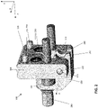
Fig. 2 depicts another perspective view of the nozzle clamp ofFig. 1 ; -
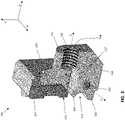
Fig. 3 depicts a cross-sectional perspective view of the nozzle clamp ofFig. 1 without illustration of an associated fastener; -
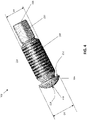
Fig. 4 depicts a fastener according to an aspect of this disclosure; -
Fig. 5 depicts a cross-sectional perspective view of the nozzle clamp ofFig. 1 shown in a first configuration according to an aspect of this disclosure; -
Fig. 6 depicts a cross-sectional perspective view of the nozzle clamp ofFig. 1 shown being transitioned between the first configuration and a second configuration; -
Fig. 7 depicts a cross-sectional perspective view of the nozzle clamp ofFig. 1 shown in the second configuration; -
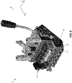
Fig. 8 depicts an isometric view of an applicator assembly according to an aspect of this disclosure; -
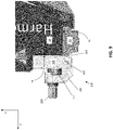
Fig. 9 depicts a side view of the applicator assembly ofFig. 8 with the nozzle clamp being in the first configuration; -
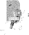
Fig. 10 depicts a side cross-sectional view of the applicator assembly ofFig. 8 with the nozzle clamp in the second configuration; and -
Fig. 11 depicts a side cross-sectional view of the applicator assembly ofFig. 8 with the nozzle clamp in the second configuration. - Aspects of the disclosure will now be described in detail with reference to the drawings, wherein like reference numbers refer to like elements throughout, unless specified otherwise.
- Referring to
Figs. 1-3 , aclamp 100 is depicted having abody 104 and anarm 150 configured to be pivotally moved relative to thebody 104. Theclamp 100 may be configured to releasably affix a nozzle to an applicator assembly, as will be described in detail below in conjunction withFigs. 9-11 . Thebody 104 may include aback wall 116 configured to contact the applicator assembly as illustrated inFig. 2 . For purposes of this disclosure, reference will be made to various axes and directions with respect to the described components. It should be appreciated that the described coordinates are for reference purposes only, and that this disclosure is not limited to the particular axes, directions, or planes described. A first axis A is defined as extending substantially orthogonal to theback wall 116 of thebody 104. A second axis B extends orthogonal to the first axis A. A third axis C extends orthogonal to the first axis A and the second axis B. Thus, a plane defined by the first axis A and the second axis B will be orthogonal to the third axis C; a plane defined by the first axis A and the third axis C will be orthogonal to the second axis B; and a plane defined by the second axis B and the third axis C will be orthogonal to the first axis A. For purposes of this disclosure, reference to one or more directions along the first, second, and/or third axes A, B, and C will include both opposing directions unless indicated otherwise. That is, for example, reference to a direction along the first axis A will include a direction along the first axis A from a first point toward a second point and also a direction from the second point toward the first point. Furthermore, reference to directions along the one or more of the first, second, and third axes A, B, and C can include directions that overlay the reference axis and directions that are offset from the references axis but that are substantially parallel to the reference axis. For example, reference to a direction along the first axis A can include a direction that overlays the first axis A or to a direction that is offset and parallel to the first axis A. - A
front wall 124 is defined on thebody 104 opposite theback wall 116. Thefront wall 124 is spaced along the first axis A from theback wall 116. A surface of thefront wall 124 may be parallel to a surface of theback wall 116. Additionally, thebody 104 may include side surfaces extending between thefront wall 124 and theback wall 116. Thearm 150 may be movably attached to thebody 104. At least a portion of thearm 150 may be disposed opposite thefront wall 124 along the first axis A. In some aspects, thearm 150 can be pivotally connected to thebody 104, such that thearm 150 can be moved toward and/or away from thefront wall 124. Thebody 104 and/or thearm 150 may include apin 122 extending therefrom or therethrough. Thearm 150 may include anaperture 152 configured to receive thepin 122 therein. In particular, theaperture 152 may be defined by surfaces arranged within thearm 150 configured to receive thepin 122. Thepin 122 may have a press-fit configuration with respect to theaperture 152. Additionally, thebody 104 may include anaperture 172 configured to receive thepin 122 therein. In particular, theaperture 172 may be defined by surfaces arranged within thebody 104 configured to receive thepin 122. Thepin 122 may have a press-fit configuration with respect to theaperture 172. Thearm 150 may be rotatable around a pivot axis D defined through thepin 122 and theaperture 152. The pivot axis D may be parallel to the second direction B. Thearm 150 may be configured to pivot around the pivot axis D in a first direction D1 and/or in a second direction D2 opposite the first direction D1. When thearm 150 is pivoted in the first direction D1, at least a portion of thearm 150 is moved towards thefront wall 124. When thearm 150 is pivoted in the second direction D2, at least the portion of thearm 150 is moved away from thefront wall 124. - In some aspects, the
body 104 may include twopins 122 on either side of thearm 150, with one of thepins 122 being spaced from the other one of thepins 122 along the second axis B. Thearm 150 may include twoapertures 152, with one of theapertures 152 being spaced from theother aperture 152 along the second axis B, such that each implementations of theaperture 152 may be configured to receive one of thepins 122 therein. Likewise, thebody 104 may include twoapertures 172, with one of theapertures 172 being spaced from theother aperture 172 along the second axis B, such that each implementations of theaperture 172 may be configured to receive one of thepins 122 therein. It will be understood that other pin and aperture arrangements are envisioned, for example, ones where one or more of thepins 122 are disposed on thearm 150 and one or more of the respective ones of theapertures 152 are disposed on thebody 104. - The
arm 150 can define abore 154 therethrough configured to receive therein a fastening element. At least a portion of thebore 154 may be disposed opposite thefront wall 124 along the first axis A. Thebore 154 may be defined between afirst end 155 and asecond end 157 spaced from thefirst end 155. Thefirst end 155 and thesecond end 157 may define surfaces that are parallel to surfaces of thefront wall 124 and theback wall 116. A bore axis E can be defined through thebore 154 and extend between thefirst end 155 and thesecond end 157. In some positions of thearm 150, the bore axis E can be substantially parallel to the first axis A. When thearm 150 is pivotally moved about thepin 122, the bore axis E can be angularly offset from the first axis A. The bore axis E can be orthogonal to the pivot axis D. - In some aspects, the fastening element may include a screw, a fastener, a bolt, and/or the like hereinafter referred to as a
bolt 200. Thebolt 200 may be translationally movable through thebore 154 along the bore axis E. Thebolt 200 can be moved in directions towards and away from thefront wall 124. Thebolt 200 may be rotatable within thebore 154 around the bore axis E in both rotational directions around the axis in order to be moved towards and away from thefront wall 124. - With continued reference to
Figs. 1 and2 and with further reference toFig. 4 , thebolt 200 may have afirst end 208 and asecond end 212 opposite thefirst end 208. Thebolt 200 may include atool interface 220 thereon configured to engage with a tool (not shown). Thetool interface 220 may be adjacent thesecond end 212. Thetool interface 220 may be configured to be engaged with a tool to cause thebolt 200 to translate along thebore 154, rotate within thebore 154, both translate and rotate relative to thebore 154 and/or the like. In some aspects, thetool interface 220 may define a geometric shape that corresponds to a geometric shape of a suitable tool, such as triangular, rectangular, pentagonal, hexagonal, octagonal, or another suitable shape. Thebolt 200 may be configured to be actuated with a driver, a wrench, or another suitable tool, and this disclosure is not limited to any particular tool or respective shape of thetool interface 220. In some aspects, thetool interface 220 may be contacted and/or manipulated by a user directly without a separate tool. For example, in some aspects, the user can use his or her hand to translate and/or rotate thebolt 200 relative to thebore 154. In this regard, thetool interface 220 may include a handle or other surface for direct user operation. - The
bolt 200 may include ahead 216 adjacent thefirst end 208. Thehead 216 may define acontact surface 228 at one end thereof. Thecontact surface 228 may be at, or adjacent to, thefirst end 208. Thecontact surface 228 may be configured to be selectively moved into and/or out of contact with thefront wall 124 of thebody 104 of theclamp 100 when thebolt 200 is moved towards or away from thefront wall 124. - A
retention surface 232 may be defined on thehead 216 opposite thecontact surface 228. Theretention surface 232 may be configured to contact thearm 150 when thebolt 200 is moved through thebore 154 away from thebody 104. The contact between theretention surface 232 and thearm 150 may preclude thebolt 200 from being moved beyond a desired distance relative to thebore 154, and may preclude thebolt 200 from being removed entirely from thebore 154. - The
bolt 200 may include anintermediate segment 204 disposed between thefirst end 208 and thesecond end 212. Theintermediate segment 204 may be disposed between thehead 216 and thetool interface 220. In some aspects, theintermediate segment 204 may includethreads 224 thereon. Thethreads 224 may be configured to engage withcorresponding threads 156 defined on the bore 154 (labeled inFig. 3 ). In one or more aspects, thebolt 200 may be configured as a male component and thebore 154 as a female component. Theintermediate segment 204 may have a cross-sectional dimension D3. In some aspects, the cross-sectional dimension D3 may be a diameter D3. - The
head 216 may have a cross-sectional dimension D4. In some aspects, the cross-sectional dimension D4 may be a diameter D4. The diameter D4 of thehead 216 may be greater than the diameter D3 of theintermediate segment 204. Thebolt 200 may be translatable through thebore 154 between theretention surface 232 on thehead 216 and thesecond end 212 of thebolt 200. As such, thehead 216 may be precluded from entering thebore 154. This may be advantageous to prevent thebolt 200 from inadvertently being fully separated from theclamp 100. - The
clamp 100 may be configured to have a first configuration, in which the nozzle is retained with respect to the housing of the applicator assembly, and a second configuration, in which the nozzle is not retained with respect to the housing. Referring toFig. 5 , a cross-sectional view of theclamp 100 in the first configuration is depicted. In this configuration, thebolt 200 is translated along the bore axis E towards thebody 104 of theclamp 100 until thebolt 200 contacts thefront wall 124 to place theclamp 100 in the first configuration. In this figure, the bore axis E can be substantially parallel to the first axis A. Specifically, thecontact surface 228 of thehead 216 may be configured to contact thefront wall 124 of thebody 104. At this point, thebolt 200 is disposed in its farthest position relative to thearm 150 along the bore axis E, i.e., this is the greatest distance between thesecond end 157 of thebore 154 and thehead 216 of thebolt 200 when thebolt 200 is within thebore 154. This can be referred to as the maximum insertion position of thebolt 200. In this arrangement, thebolt 200 can be secured to the arm 150 (e.g., via thethreads 224 on thebolt 200 and thecorresponding threads 156 on the interior of the bore 154). When thebolt 200 is in contact with thefront wall 124, thearm 150 is precluded from pivoting about the pivot axis D in at least one direction. For example, thearm 150 can be precluded from pivoting about the pivot axis D along the direction D1 towards thefront wall 124. This is due to thebolt 200 contacting thefront wall 124 and physically blocking movement in this direction. - Referring to
Fig. 6 , the bolt200 is shown having been moved through thebore 154 along the bore axis E away from thefront wall 124. Thehead 216 may be configured to contact thearm 150 adjacent thebore 154. Theretention surface 232 may contact thearm 150 at thesecond end 157 of thebore 154 to preclude thehead 216 from entering thebore 154. In this figure, thebolt 200 is shown in its farthest position within thebore 154 in the direction toward thefirst end 155 of thebore 154 along the bore axis E. This can be referred to as the maximum extraction position of thebolt 200. Thebolt 200 may be movable to any position between the maximum insertion position shown inFig. 5 above and the maximum extraction position shown inFig. 6 here. Because thecontact surface 228 of thehead 216 is no longer in contact with thefront wall 124 of thebody 104, thearm 150 is not precluded from being rotated about the pivot axis D in the direction D1 toward thefront wall 124. In this position, a user may actuate rotation of thearm 150 in the direction D1 by applying a force to thearm 150 along the first axis A towards thefront wall 124 to place theclamp 100 and the second configuration. - Referring to
Fig. 7 , theclamp 100 is shown in the second configuration, where thearm 150 has been pivoted along the first rotational direction D1 towards thefront wall 124. The distance that thearm 150 may be pivoted from the first configuration to the second configuration may depend on the distance between thefront wall 124 and thehead 216 of thebolt 200, the distance between thefront wall 124 and the arm 150 (e.g., a portion of thearm 150 adjacent thesecond end 157 of the bore 154), or between another portion of thebody 104 and a portion of thearm 150 and/or thebolt 200. Thearm 150 can be pivoted in the first rotational direction D1 until further movement is precluded by contact between one or more components of thebody 104 and one or more components of thearm 150 and/or thebolt 200. In some aspects, the distance that thearm 150 can be pivoted along the first rotational direction D1 can be controlled by the distance that thebolt 200 is moved along the bore axis E away from thefront wall 124. For example, when thebolt 200 is moved to its maximum extraction position along thebore 154 away from the front wall 124 (seeFig. 6 ), this can correspond to a maximum distance of pivoting of thearm 150 in the direction D1. Thebolt 200 may be moved along the bore axis E to a position between its maximum inserted position (shown inFig. 5 ) and its maximum extracted position (shown inFigs. 6 and7 ). Accordingly, when thebolt 200 is not at its maximum extracted position, the distance that thearm 150 can pivot in the direction D1 can be proportionally less than when thebolt 200 is in its maximum extracted position. - Referring again to
Figs. 2 and3 , theclamp 100 can include a nozzle engagement interface configured to releasably contact the nozzle of the applicator assembly. The engagement interface may include afirst protrusion 162 that may extend from thearm 150. Thefirst protrusion 162 may be movable when thearm 150 is moved around the pivot axis D. Thefirst protrusion 162 can be any suitable shape or dimension and should be configured to contact a portion of the nozzle, as will be described below. In some aspects, the engagement interface may include asecond protrusion 166 that may extend from thearm 150. Thesecond protrusion 166 may be, at least partly, parallel to thefirst protrusion 162. Thesecond protrusion 166 may be configured to contact another portion of the nozzle, as will be described below. Arecess 170 may be defined between thefirst protrusion 162 and thesecond protrusion 166 and be configured to receive the nozzle therein. - Turning to
Figs. 8-11 , an exemplary implementation of theapplicator assembly 10 is shown having ahousing 14. One ormore dispensing assemblies 18 can be disposed on, or in, thehousing 14. The one ormore dispensing assemblies 18 may be configured to receive an application material from a source (not shown) and to guide the application material to one or more connected arrangements of thenozzles 22. The application material can pass through thenozzles 22 and be dispensed onto a suitable substrate (not shown). Eachnozzle 22 can be retained relative to thehousing 14 by aclamp 100, such as described above. In some aspects, theapplicator assembly 10 can include a single implementation of one of thedispensing assemblies 18 and a single implementation of thenozzle 22 held by a single implementation of theclamp 100. In other aspects, theapplicator assembly 10 can include a plurality of dispensingassemblies 18, a plurality of theclamp 100, and a plurality of thenozzles 22. The plurality of dispensingassemblies 18, theclamp 100, and thenozzles 22 can be arranged side by side in a serial manner, for example, along the second axis B as shown inFig. 8 . Eachnozzle 22 can be affixed to thehousing 14 with an individual configuration of theclamp 100. Alternatively, a plurality of thenozzle 22 may be held by a single implementation of theclamp 100. -
Figs. 8 and9 depict anozzle 22 that is secured to thehousing 14 via aclamp 100. Theclamp 100 is in the first configuration. Thenozzle 22 may be held securely against thehousing 14 at anozzle contact surface 15. Thenozzle contact surface 15 may be arranged below thehousing 14 of theapplicator assembly 10. It is important that thenozzle 22 be securely affixed to thenozzle contact surface 15 to ensure that the application material is properly discharged from thedispenser assembly 18 into thenozzle 22. Theclamp 100 can be affixed to thehousing 14 at aclamp surface 16. Theclamp 100 can be affixed to thehousing 14 via one ormore fasteners 101. Thefasteners 101 may be any suitable fasteners, such as bolts, screws, clamps, and/or the like. Thefasteners 101 can extend through thebody 104, or otherwise secure thebody 104, and releasably connect with thehousing 14. Theback wall 116 of thebody 104 may be configured to be securely in contact with theclamp surface 16 of thehousing 14 when theclamp 100 is affixed to thehousing 14. - When the
nozzle 22 is held against thenozzle contact surface 15 and theclamp 100 is in the first configuration, thenozzle 22 may be precluded from movement away from thenozzle contact surface 15. Thefirst protrusion 162 on theclamp 100 may be configured to contact thenozzle 22 and apply a clamping force to thenozzle 22 along the third axis C towards thenozzle contact surface 15. This secures thenozzle 22 to thenozzle contact surface 15 and precludes thenozzle 22 from being moved away from thenozzle contact surface 15. - To release the
nozzle 22 from thehousing 14, theclamp 100 can be moved to the second configuration as described above. Referring toFigs. 10 and11 , theclamp 100 is shown in the second configuration. As thearm 150 is pivoted to move theclamp 100 to the second configuration, thefirst protrusion 162 is moved away from thenozzle 22. When thefirst protrusion 162 is moved away from thenozzle 22, thefirst protrusion 162 no longer applies a clamping force onto thenozzle 22 towards thenozzle contact surface 15. At this time, thenozzle 22 is no longer secured to thehousing 14 and can be moved relative to thehousing 14 or removed from theapplicator assembly 10. - In some aspects, the
clamp 100 can include thesecond protrusion 166 disposed on thearm 150. When theclamp 100 is moved to the second configuration, thesecond protrusion 166 contacts thenozzle 22 and applies a force to thenozzle 22 away from thenozzle contact surface 15. This can apply force to thenozzle 22 and cause thenozzle 22 to release from thenozzle contact surface 15 and can facilitate disengagement and removal of thenozzle 22 from thehousing 14. Thenozzle 22 can be disposed in therecess 170 defined between thefirst protrusion 162 and thesecond protrusion 166. When theclamp 100 is in the second configuration, thenozzle 22 may still be retained in therecess 170 even though thenozzle 22 is spaced from thenozzle contact surface 15. This can facilitate locating and removing thenozzle 22 and avoid thenozzle 22 falling away from thehousing 14 due to gravity once thenozzle 22 is no longer clamped to thehousing 14. This can also facilitate introducing a different or a new configuration of thenozzle 22 by providing a space for thenozzle 22 to be placed before affixing it to thehousing 14. - To affix a
nozzle 22 to thehousing 14, thenozzle 22 may be arranged in therecess 170 when theclamp 100 is in the second configuration. Theclamp 100 can then be moved to the first configuration by rotating thearm 150 in a second rotational direction D2 opposite the first rotational direction D1 until thenozzle 22 fully contacts thenozzle contact surface 15 and thefirst protrusion 162 rigidly pushes against thenozzle 22 along the third axis C towards thenozzle contact surface 15. To secure theclamp 100 in the first configuration, thebolt 200 can be moved to its maximum insertion position as described earlier. - When the
bolt 200 is in its maximum insertion position, thehead 216 of thebolt 200 contacts thefront wall 124 at thecontact surface 228 on thehead 216 of thebolt 200. Thefront wall 124 may include sturdy metallic portions such as steel and may be precluded from being damaged by repetitive contact of thehead 216 of the bolt200. Thebolt 200 may be configured to only contact thefront wall 124 of theclamp 100 and not contact thehousing 14 directly. This configuration avoids and/or reduces the likelihood of damaging the surface of thehousing 14. If thebolt 200 contacts thehousing 14, the repeated contacting can cause damage to the structure of thehousing 14 and can cause dents, notches, and/or like damage to be formed on thehousing 14. The formation of such dents or notches would increase the necessary insertion distance of thebolt 200 to effectively retain theclamp 100 in the first configuration. Over time, such dents would result in theclamp 100 being moved out of the first configuration earlier than desired, which would release the clamping force from thefirst protrusion 162 onto thenozzle 22 towards thenozzle contact surface 15. This can result in thenozzle 22 not being rigidly affixed to thenozzle contact surface 15 as desired and can result in material leaking out between thehousing 14 and thenozzle 22 and/or in undesirable pressure changes as the material is being moved towards and through thenozzle 22. This can result in undesired discharging effects of the material onto the substrate. Moreover, this may result in possible misalignment of thenozzle 22. - In the embodiments of the
clamp 100 disclosed herein, theclamp 100 includes afront wall 124 that is configured to be contacted by thebolt 200. Thefront wall 124 can include a harder material than the rest of thehousing 14, for example, steel. The steel configurations of thefront wall 124 do not wear as quickly or as easily as the material of thehousing 14, and thus dents and/or other damage are substantially avoided due to repeated contact and forces exerted by thebolt 200 when theclamp 100 is in the first configuration. - In some aspects, the
clamp 100 may include one ormore seals 130 disposed on theback wall 116. The one ormore seals 130 may be configured to sealingly engage with corresponding air inlet holes (not shown) on thehousing 14. Thebody 104 of theclamp 100 may include one or more studs or dowels 134 configured to be received into complementary apertures (not shown) on thehousing 14 to facilitate alignment of theclamp 100 with thehousing 14. - While systems and methods have been described in connection with the various embodiments of the various figures, it will be appreciated by those skilled in the art that changes could be made to the embodiments without departing from the broad inventive concept thereof. It is understood, therefore, that this disclosure is not limited to the particular embodiments disclosed, and it is intended to cover modifications within the spirit and scope of the present disclosure as defined by the claims.
- The invention is further descripted by the following embodiments, wherein:
- Embodiment 1. A nozzle clamp configured to secure a nozzle to a housing of an applicator assembly, the nozzle clamp comprising:
- a body defining a first surface configured to contact the housing and a second surface opposite the first surface;
- an arm pivotally connected to the body, the arm being configured to move between a first position and a second position relative to the body, the arm comprising:
- a bore extending therethrough; and
- a protrusion extending therefrom, the protrusion being configured to contact the nozzle; and
- a fastener movable within the bore of the arm, the fastener being configured to contact the second surface of the body,
- wherein the nozzle clamp is movable between a first configuration and a second configuration,
- wherein when the nozzle clamp is in the first configuration, the fastener is in contact with the second surface of the body, and the arm is precluded from being pivotally rotated relative to the body, and
- wherein when the nozzle clamp is in the second configuration, the fastener is not in contact with the second surface of the body, and the arm is permitted to be pivotally rotated relative to the body.
- Embodiment 2. The nozzle clamp of Embodiment 1, wherein the nozzle clamp comprises steel.
- Embodiment 3. The nozzle clamp of Embodiment 1, wherein the fastener includes threads thereon, and the bore includes complementary threads therein, the threads on the fastener being configured to engage with the threads on the bore.
- Embodiment 4. The nozzle clamp of Embodiment 1, wherein the protrusion on the arm is a first protrusion, and the arm includes a second protrusion spaced from the first protrusion, the second protrusion being configured to contact the nozzle.
- Embodiment 5. The nozzle clamp of Embodiment 1, wherein the bore defines a first cross-sectional diameter, the fastener defines a second cross-sectional diameter, and the second cross-sectional diameter is less than the first cross-sectional diameter.
- Embodiment 6. The nozzle clamp of Embodiment 5, wherein the fastener includes a head portion defining a third cross-sectional diameter that is greater than the first cross-sectional diameter of the bore.
- Embodiment 7. The nozzle clamp of Embodiment 1, wherein the second surface of the body faces the bore of the arm.
- Embodiment 8. The nozzle clamp of Embodiment 1,
- wherein the nozzle clamp comprises steel;
- wherein the fastener includes threads thereon, and the bore includes complementary threads therein, the threads on the fastener being configured to engage with the threads on the bore; and
- wherein the protrusion on the arm is a first protrusion, and the arm includes a second protrusion spaced from the first protrusion, the second protrusion being configured to contact the nozzle.
- Embodiment 9. An applicator assembly for applying a material to a substrate, the applicator assembly comprising:
- a housing;
- a dispensing assembly configured to receive the material from a material source and to cause discharging of the material therefrom;
- a nozzle configured to be affixed to the housing, the nozzle further being configured to receive the material from the dispensing assembly and to discharge the material from the nozzle; and
- a nozzle clamp configured to affix the nozzle to the housing, the nozzle clamp comprising:
- a body defining a first surface configured to contact the housing and a second surface opposite the first surface;
- an arm pivotally connected to the body, the arm being configured to move between a first position and a second position relative to the body, the arm comprising:
- a bore extending therethrough; and
- a protrusion extending therefrom, the protrusion being configured to contact the nozzle; and
- a fastener movable within the bore of the arm, the fastener being configured to contact the second surface of the body,
- wherein the nozzle clamp is movable between a first configuration and a second configuration,
- wherein when the nozzle clamp is in the first configuration, the fastener is in contact with the second surface of the body, and the arm is precluded from being pivotally rotated relative to the body, and
- wherein when the nozzle clamp is in the second configuration, the fastener is not in contact with the second surface of the body, and the arm is permitted to be pivotally rotated relative to the body.
-
Embodiment 10. The applicator assembly of Embodiment 9, further comprising a heater configured to heat the material being moved through the applicator assembly. - Embodiment 11. The applicator assembly of Embodiment 9, wherein the nozzle clamp comprises steel.
- Embodiment 12. The applicator assembly of Embodiment 9, wherein the fastener includes threads thereon, and the bore includes complementary threads therein, the threads on the fastener being configured to engage with the threads on the bore.
- Embodiment 13. The applicator assembly of Embodiment 9, wherein the protrusion on the arm is a first protrusion, and the arm includes a second protrusion spaced from the first protrusion, the second protrusion being configured to contact the nozzle.
-
Embodiment 14. The applicator assembly of Embodiment 9, wherein the bore defines a first cross-sectional diameter, the fastener defines a second cross-sectional diameter, and the second cross-sectional diameter is less than the first cross-sectional diameter. -
Embodiment 15. The applicator assembly ofEmbodiment 14, wherein the fastener includes a head portion defining a third cross-sectional diameter that is greater than the first cross-sectional diameter of the bore. -
Embodiment 16. The applicator assembly of Embodiment 9, wherein the second surface of the body faces the bore of the arm. - Embodiment 17. The applicator assembly of Embodiment 9,
- wherein the nozzle clamp comprises steel;
- wherein the fastener includes threads thereon, and the bore includes complementary threads therein, the threads on the fastener being configured to engage with the threads on the bore; and
- wherein the protrusion on the arm is a first protrusion, and the arm includes a second protrusion spaced from the first protrusion, the second protrusion being configured to contact the nozzle.
Claims (16)
- A nozzle clamp configured to secure a nozzle to a housing of an applicator assembly, the nozzle clamp comprising:a body defining a first surface configured to contact the housing and a second surface opposite the first surface;an arm pivotally connected to the body, the arm being configured to move between a first position and a second position relative to the body, the arm comprising:a bore extending therethrough; anda protrusion extending therefrom, the protrusion being configured to contact the nozzle; anda fastener movable within the bore of the arm, the fastener being configured to contact the second surface of the body,wherein the nozzle clamp is movable between a first configuration and a second configuration,wherein when the nozzle clamp is in the first configuration, the fastener is in contact with the second surface of the body, and the arm is precluded from being pivotally rotated relative to the body, andwherein when the nozzle clamp is in the second configuration, the fastener is not in contact with the second surface of the body, and the arm is permitted to be pivotally rotated relative to the body.
- The nozzle clamp of claim 1, wherein the nozzle clamp comprises steel.
- The nozzle clamp of claim 1, wherein the fastener includes threads thereon, and the bore includes complementary threads therein, the threads on the fastener being configured to engage with the threads on the bore.
- The nozzle clamp of claim 1, wherein the protrusion on the arm is a first protrusion, and the arm includes a second protrusion spaced from the first protrusion, the second protrusion being configured to contact the nozzle.
- The nozzle clamp of claim 1, wherein the bore defines a first cross-sectional diameter, the fastener defines a second cross-sectional diameter, and the second cross-sectional diameter is less than the first cross-sectional diameter.
- The nozzle clamp of claim 5, wherein the fastener includes a head portion defining a third cross-sectional diameter that is greater than the first cross-sectional diameter of the bore.
- The nozzle clamp of claim 1, wherein the second surface of the body faces the bore of the arm.
- The nozzle clamp of claim 1,wherein the nozzle clamp comprises steel;wherein the fastener includes threads thereon, and the bore includes complementary threads therein, the threads on the fastener being configured to engage with the threads on the bore; andwherein the protrusion on the arm is a first protrusion, and the arm includes a second protrusion spaced from the first protrusion, the second protrusion being configured to contact the nozzle.
- An applicator assembly for applying a material to a substrate, the applicator assembly comprising:a housing;a dispensing assembly configured to receive the material from a material source and to cause discharging of the material therefrom;a nozzle configured to be affixed to the housing, the nozzle further being configured to receive the material from the dispensing assembly and to discharge the material from the nozzle; anda nozzle clamp configured to affix the nozzle to the housing, the nozzle clamp comprising:a body defining a first surface configured to contact the housing and a second surface opposite the first surface;an arm pivotally connected to the body, the arm being configured to move between a first position and a second position relative to the body, the arm comprising:a bore extending therethrough; anda protrusion extending therefrom, the protrusion being configured to contact the nozzle; anda fastener movable within the bore of the arm, the fastener being configured to contact the second surface of the body,wherein the nozzle clamp is movable between a first configuration and a second configuration,wherein when the nozzle clamp is in the first configuration, the fastener is in contact with the second surface of the body, and the arm is precluded from being pivotally rotated relative to the body, andwherein when the nozzle clamp is in the second configuration, the fastener is not in contact with the second surface of the body, and the arm is permitted to be pivotally rotated relative to the body.
- The applicator assembly of claim 9, wherein the nozzle clamp comprises steel.
- The applicator assembly of claim 9, wherein the fastener includes threads thereon, and the bore includes complementary threads therein, the threads on the fastener being configured to engage with the threads on the bore.
- The applicator assembly of claim 9, wherein the protrusion on the arm is a first protrusion, and the arm includes a second protrusion spaced from the first protrusion, the second protrusion being configured to contact the nozzle.
- The applicator assembly of claim 9, wherein the bore defines a first cross-sectional diameter, the fastener defines a second cross-sectional diameter, and the second cross-sectional diameter is less than the first cross-sectional diameter.
- The applicator assembly of claim 13, wherein the fastener includes a head portion defining a third cross-sectional diameter that is greater than the first cross-sectional diameter of the bore.
- The applicator assembly of claim 9, wherein the second surface of the body faces the bore of the arm.
- The applicator assembly of claim 9,wherein the nozzle clamp comprises steel;wherein the fastener includes threads thereon, and the bore includes complementary threads therein, the threads on the fastener being configured to engage with the threads on the bore; andwherein the protrusion on the arm is a first protrusion, and the arm includes a second protrusion spaced from the first protrusion, the second protrusion being configured to contact the nozzle.
Applications Claiming Priority (1)
| Application Number | Priority Date | Filing Date | Title |
|---|---|---|---|
| US17/245,812 US11484905B1 (en) | 2021-04-30 | 2021-04-30 | Spray nozzle clamp |
Publications (1)
| Publication Number | Publication Date |
|---|---|
| EP4088825A1 true EP4088825A1 (en) | 2022-11-16 |
Family
ID=81386614
Family Applications (1)
| Application Number | Title | Priority Date | Filing Date |
|---|---|---|---|
| EP22169679.2A Pending EP4088825A1 (en) | 2021-04-30 | 2022-04-25 | Dispensing nozzle clamp |
Country Status (4)
| Country | Link |
|---|---|
| US (1) | US11484905B1 (en) |
| EP (1) | EP4088825A1 (en) |
| JP (1) | JP2022171589A (en) |
| CN (1) | CN115254503B (en) |
Families Citing this family (1)
| Publication number | Priority date | Publication date | Assignee | Title |
|---|---|---|---|---|
| USD1047680S1 (en) * | 2021-04-30 | 2024-10-22 | Nordson Corporation | Spray nozzle clamp |
Citations (3)
| Publication number | Priority date | Publication date | Assignee | Title |
|---|---|---|---|---|
| US20020134858A1 (en) * | 2001-03-22 | 2002-09-26 | Gressett Charles A. | Universal dispensing system for air assisted extrusion of liquid filaments |
| US20050274317A1 (en) * | 2004-04-30 | 2005-12-15 | De Leeuw Victor | Applicator head, applicator nozzle arrangement, adaptor plate and mounting plate |
| US20160339470A1 (en) * | 2015-05-22 | 2016-11-24 | Nordson Corporation | Piezoelectric jetting system with quick release jetting valve |
Family Cites Families (10)
| Publication number | Priority date | Publication date | Assignee | Title |
|---|---|---|---|---|
| US4613078A (en) * | 1984-04-09 | 1986-09-23 | Nordson Corporation | Quick replaceable nozzle assembly |
| US4781252A (en) * | 1987-07-15 | 1988-11-01 | Citgo Petroleum Corp. | Storage tank fire extinguishing apparatus |
| US4774109A (en) * | 1987-07-21 | 1988-09-27 | Nordson Corporation | Method and apparatus for applying narrow, closely spaced beads of viscous liquid to a substrate |
| US5389151A (en) * | 1993-03-15 | 1995-02-14 | Nordson Corporation | Interchangeable contact/non-contact dispensing system |
| US6210141B1 (en) * | 1998-02-10 | 2001-04-03 | Nordson Corporation | Modular die with quick change die tip or nozzle |
| EP1243342B9 (en) * | 2001-03-22 | 2010-02-17 | Nordson Corporation | Universal dispensing system for air assisted extrusion of liquid filaments |
| DE202006016674U1 (en) * | 2006-10-27 | 2007-02-22 | Nordson Corporation, Westlake | Application device for flat application of liquid material, especially hot melt glue, has clamping device for fastening of nozzle arrangement on basic body |
| DE102012216817A1 (en) * | 2012-09-19 | 2014-03-20 | Nordson Corporation | Metering device for a fluid |
| EP3509759B1 (en) * | 2016-09-08 | 2020-11-04 | Nordson Corporation | Applicator with diverter plate |
| US10500604B2 (en) * | 2018-02-09 | 2019-12-10 | Nordson Corporation | Liquid adhesive dispensing system |
-
2021
- 2021-04-30 US US17/245,812 patent/US11484905B1/en active Active
-
2022
- 2022-04-20 JP JP2022069245A patent/JP2022171589A/en active Pending
- 2022-04-25 EP EP22169679.2A patent/EP4088825A1/en active Pending
- 2022-04-27 CN CN202210452682.4A patent/CN115254503B/en active Active
Patent Citations (3)
| Publication number | Priority date | Publication date | Assignee | Title |
|---|---|---|---|---|
| US20020134858A1 (en) * | 2001-03-22 | 2002-09-26 | Gressett Charles A. | Universal dispensing system for air assisted extrusion of liquid filaments |
| US20050274317A1 (en) * | 2004-04-30 | 2005-12-15 | De Leeuw Victor | Applicator head, applicator nozzle arrangement, adaptor plate and mounting plate |
| US20160339470A1 (en) * | 2015-05-22 | 2016-11-24 | Nordson Corporation | Piezoelectric jetting system with quick release jetting valve |
Also Published As
| Publication number | Publication date |
|---|---|
| US11484905B1 (en) | 2022-11-01 |
| CN115254503A (en) | 2022-11-01 |
| JP2022171589A (en) | 2022-11-11 |
| CN115254503B (en) | 2025-10-03 |
| US20220347709A1 (en) | 2022-11-03 |
Similar Documents
| Publication | Publication Date | Title |
|---|---|---|
| CN210171741U (en) | Spray gun and valve core for spray gun | |
| TWI790025B (en) | Mechanism and method for mechanically and automatically changing tool on end shaft of robot arm | |
| US11484905B1 (en) | Spray nozzle clamp | |
| US5782571A (en) | Tool mount for automatic coupling with robotic equipment | |
| JP4931031B2 (en) | Screw-fit connector | |
| US9216457B2 (en) | Holder assembly for a cutting tool insert and a cutting tool | |
| US9302356B2 (en) | Guide assembly | |
| US8556196B2 (en) | Quick change nozzle | |
| US8061564B2 (en) | Liquid dispensing apparatus including an attachment member | |
| CN109310900B (en) | Protective caps for sprinkler nozzles, their application and method for installing and/or removing sprinkler nozzles at pipelines | |
| EP0006836B1 (en) | Means and method for removal of seat rings in ball valves | |
| US7134642B2 (en) | Vacuum gate valve | |
| US7399361B2 (en) | Apparatus for applying fluid to a substrate | |
| JPH03504153A (en) | Capture self-locking mechanism | |
| CN104080543B (en) | Rotary module | |
| US11712731B2 (en) | Adapter, stretcher-leveller and method for operating a stretcher-leveller | |
| US20240203721A1 (en) | Multi-device removal and installation tool | |
| CN105705251A (en) | Device for supplying a sprayer with a liquid coating product and tool for mounting/dismounting such a device | |
| US20230268705A1 (en) | Connector demating tool with parallel plates | |
| US20230017417A1 (en) | Multi-device removal and installation tool | |
| US4395062A (en) | Cover hold down mechanism | |
| KR102198228B1 (en) | Magnetic Separator | |
| US20190368031A1 (en) | Fixture for pvd coating of spade bits | |
| CN114616400B (en) | Fluid device for suction gripping | |
| US10020629B1 (en) | Hotstick tool for assisting linemen tapping high power lines using wedge tap connectors |
Legal Events
| Date | Code | Title | Description |
|---|---|---|---|
| PUAI | Public reference made under article 153(3) epc to a published international application that has entered the european phase |
Free format text: ORIGINAL CODE: 0009012 |
|
| STAA | Information on the status of an ep patent application or granted ep patent |
Free format text: STATUS: THE APPLICATION HAS BEEN PUBLISHED |
|
| AK | Designated contracting states |
Kind code of ref document: A1 Designated state(s): AL AT BE BG CH CY CZ DE DK EE ES FI FR GB GR HR HU IE IS IT LI LT LU LV MC MK MT NL NO PL PT RO RS SE SI SK SM TR |
|
| STAA | Information on the status of an ep patent application or granted ep patent |
Free format text: STATUS: REQUEST FOR EXAMINATION WAS MADE |
|
| 17P | Request for examination filed |
Effective date: 20230516 |
|
| RBV | Designated contracting states (corrected) |
Designated state(s): AL AT BE BG CH CY CZ DE DK EE ES FI FR GB GR HR HU IE IS IT LI LT LU LV MC MK MT NL NO PL PT RO RS SE SI SK SM TR |
|
| P01 | Opt-out of the competence of the unified patent court (upc) registered |
Effective date: 20230528 |
|
| STAA | Information on the status of an ep patent application or granted ep patent |
Free format text: STATUS: EXAMINATION IS IN PROGRESS |
|
| 17Q | First examination report despatched |
Effective date: 20240731 |