EP4088687A1 - Biased capsule for transcatheter valve repair - Google Patents
Biased capsule for transcatheter valve repair Download PDFInfo
- Publication number
- EP4088687A1 EP4088687A1 EP22158962.5A EP22158962A EP4088687A1 EP 4088687 A1 EP4088687 A1 EP 4088687A1 EP 22158962 A EP22158962 A EP 22158962A EP 4088687 A1 EP4088687 A1 EP 4088687A1
- Authority
- EP
- European Patent Office
- Prior art keywords
- delivery device
- compression spring
- implant
- stop
- biasing element
- Prior art date
- Legal status (The legal status is an assumption and is not a legal conclusion. Google has not performed a legal analysis and makes no representation as to the accuracy of the status listed.)
- Granted
Links
Images




Classifications
-
- A—HUMAN NECESSITIES
- A61—MEDICAL OR VETERINARY SCIENCE; HYGIENE
- A61F—FILTERS IMPLANTABLE INTO BLOOD VESSELS; PROSTHESES; DEVICES PROVIDING PATENCY TO, OR PREVENTING COLLAPSING OF, TUBULAR STRUCTURES OF THE BODY, e.g. STENTS; ORTHOPAEDIC, NURSING OR CONTRACEPTIVE DEVICES; FOMENTATION; TREATMENT OR PROTECTION OF EYES OR EARS; BANDAGES, DRESSINGS OR ABSORBENT PADS; FIRST-AID KITS
- A61F2/00—Filters implantable into blood vessels; Prostheses, i.e. artificial substitutes or replacements for parts of the body; Appliances for connecting them with the body; Devices providing patency to, or preventing collapsing of, tubular structures of the body, e.g. stents
- A61F2/02—Prostheses implantable into the body
- A61F2/24—Heart valves ; Vascular valves, e.g. venous valves; Heart implants, e.g. passive devices for improving the function of the native valve or the heart muscle; Transmyocardial revascularisation [TMR] devices; Valves implantable in the body
- A61F2/2427—Devices for manipulating or deploying heart valves during implantation
- A61F2/2436—Deployment by retracting a sheath
-
- A—HUMAN NECESSITIES
- A61—MEDICAL OR VETERINARY SCIENCE; HYGIENE
- A61F—FILTERS IMPLANTABLE INTO BLOOD VESSELS; PROSTHESES; DEVICES PROVIDING PATENCY TO, OR PREVENTING COLLAPSING OF, TUBULAR STRUCTURES OF THE BODY, e.g. STENTS; ORTHOPAEDIC, NURSING OR CONTRACEPTIVE DEVICES; FOMENTATION; TREATMENT OR PROTECTION OF EYES OR EARS; BANDAGES, DRESSINGS OR ABSORBENT PADS; FIRST-AID KITS
- A61F2/00—Filters implantable into blood vessels; Prostheses, i.e. artificial substitutes or replacements for parts of the body; Appliances for connecting them with the body; Devices providing patency to, or preventing collapsing of, tubular structures of the body, e.g. stents
- A61F2/02—Prostheses implantable into the body
- A61F2/24—Heart valves ; Vascular valves, e.g. venous valves; Heart implants, e.g. passive devices for improving the function of the native valve or the heart muscle; Transmyocardial revascularisation [TMR] devices; Valves implantable in the body
- A61F2/2442—Annuloplasty rings or inserts for correcting the valve shape; Implants for improving the function of a native heart valve
-
- A—HUMAN NECESSITIES
- A61—MEDICAL OR VETERINARY SCIENCE; HYGIENE
- A61F—FILTERS IMPLANTABLE INTO BLOOD VESSELS; PROSTHESES; DEVICES PROVIDING PATENCY TO, OR PREVENTING COLLAPSING OF, TUBULAR STRUCTURES OF THE BODY, e.g. STENTS; ORTHOPAEDIC, NURSING OR CONTRACEPTIVE DEVICES; FOMENTATION; TREATMENT OR PROTECTION OF EYES OR EARS; BANDAGES, DRESSINGS OR ABSORBENT PADS; FIRST-AID KITS
- A61F2/00—Filters implantable into blood vessels; Prostheses, i.e. artificial substitutes or replacements for parts of the body; Appliances for connecting them with the body; Devices providing patency to, or preventing collapsing of, tubular structures of the body, e.g. stents
- A61F2/02—Prostheses implantable into the body
- A61F2/24—Heart valves ; Vascular valves, e.g. venous valves; Heart implants, e.g. passive devices for improving the function of the native valve or the heart muscle; Transmyocardial revascularisation [TMR] devices; Valves implantable in the body
- A61F2/2412—Heart valves ; Vascular valves, e.g. venous valves; Heart implants, e.g. passive devices for improving the function of the native valve or the heart muscle; Transmyocardial revascularisation [TMR] devices; Valves implantable in the body with soft flexible valve members, e.g. tissue valves shaped like natural valves
- A61F2/2418—Scaffolds therefor, e.g. support stents
-
- A—HUMAN NECESSITIES
- A61—MEDICAL OR VETERINARY SCIENCE; HYGIENE
- A61F—FILTERS IMPLANTABLE INTO BLOOD VESSELS; PROSTHESES; DEVICES PROVIDING PATENCY TO, OR PREVENTING COLLAPSING OF, TUBULAR STRUCTURES OF THE BODY, e.g. STENTS; ORTHOPAEDIC, NURSING OR CONTRACEPTIVE DEVICES; FOMENTATION; TREATMENT OR PROTECTION OF EYES OR EARS; BANDAGES, DRESSINGS OR ABSORBENT PADS; FIRST-AID KITS
- A61F2/00—Filters implantable into blood vessels; Prostheses, i.e. artificial substitutes or replacements for parts of the body; Appliances for connecting them with the body; Devices providing patency to, or preventing collapsing of, tubular structures of the body, e.g. stents
- A61F2/02—Prostheses implantable into the body
- A61F2/24—Heart valves ; Vascular valves, e.g. venous valves; Heart implants, e.g. passive devices for improving the function of the native valve or the heart muscle; Transmyocardial revascularisation [TMR] devices; Valves implantable in the body
- A61F2/2442—Annuloplasty rings or inserts for correcting the valve shape; Implants for improving the function of a native heart valve
- A61F2/2466—Delivery devices therefor
-
- A—HUMAN NECESSITIES
- A61—MEDICAL OR VETERINARY SCIENCE; HYGIENE
- A61F—FILTERS IMPLANTABLE INTO BLOOD VESSELS; PROSTHESES; DEVICES PROVIDING PATENCY TO, OR PREVENTING COLLAPSING OF, TUBULAR STRUCTURES OF THE BODY, e.g. STENTS; ORTHOPAEDIC, NURSING OR CONTRACEPTIVE DEVICES; FOMENTATION; TREATMENT OR PROTECTION OF EYES OR EARS; BANDAGES, DRESSINGS OR ABSORBENT PADS; FIRST-AID KITS
- A61F2/00—Filters implantable into blood vessels; Prostheses, i.e. artificial substitutes or replacements for parts of the body; Appliances for connecting them with the body; Devices providing patency to, or preventing collapsing of, tubular structures of the body, e.g. stents
- A61F2/95—Instruments specially adapted for placement or removal of stents or stent-grafts
- A61F2/9517—Instruments specially adapted for placement or removal of stents or stent-grafts handle assemblies therefor
-
- A—HUMAN NECESSITIES
- A61—MEDICAL OR VETERINARY SCIENCE; HYGIENE
- A61F—FILTERS IMPLANTABLE INTO BLOOD VESSELS; PROSTHESES; DEVICES PROVIDING PATENCY TO, OR PREVENTING COLLAPSING OF, TUBULAR STRUCTURES OF THE BODY, e.g. STENTS; ORTHOPAEDIC, NURSING OR CONTRACEPTIVE DEVICES; FOMENTATION; TREATMENT OR PROTECTION OF EYES OR EARS; BANDAGES, DRESSINGS OR ABSORBENT PADS; FIRST-AID KITS
- A61F2/00—Filters implantable into blood vessels; Prostheses, i.e. artificial substitutes or replacements for parts of the body; Appliances for connecting them with the body; Devices providing patency to, or preventing collapsing of, tubular structures of the body, e.g. stents
- A61F2/95—Instruments specially adapted for placement or removal of stents or stent-grafts
- A61F2/962—Instruments specially adapted for placement or removal of stents or stent-grafts having an outer sleeve
- A61F2/966—Instruments specially adapted for placement or removal of stents or stent-grafts having an outer sleeve with relative longitudinal movement between outer sleeve and prosthesis, e.g. using a push rod
- A61F2/9661—Instruments specially adapted for placement or removal of stents or stent-grafts having an outer sleeve with relative longitudinal movement between outer sleeve and prosthesis, e.g. using a push rod the proximal portion of the stent or stent-graft is released first
-
- A—HUMAN NECESSITIES
- A61—MEDICAL OR VETERINARY SCIENCE; HYGIENE
- A61F—FILTERS IMPLANTABLE INTO BLOOD VESSELS; PROSTHESES; DEVICES PROVIDING PATENCY TO, OR PREVENTING COLLAPSING OF, TUBULAR STRUCTURES OF THE BODY, e.g. STENTS; ORTHOPAEDIC, NURSING OR CONTRACEPTIVE DEVICES; FOMENTATION; TREATMENT OR PROTECTION OF EYES OR EARS; BANDAGES, DRESSINGS OR ABSORBENT PADS; FIRST-AID KITS
- A61F2/00—Filters implantable into blood vessels; Prostheses, i.e. artificial substitutes or replacements for parts of the body; Appliances for connecting them with the body; Devices providing patency to, or preventing collapsing of, tubular structures of the body, e.g. stents
- A61F2/02—Prostheses implantable into the body
- A61F2/24—Heart valves ; Vascular valves, e.g. venous valves; Heart implants, e.g. passive devices for improving the function of the native valve or the heart muscle; Transmyocardial revascularisation [TMR] devices; Valves implantable in the body
- A61F2/2427—Devices for manipulating or deploying heart valves during implantation
- A61F2/2439—Expansion controlled by filaments
-
- A—HUMAN NECESSITIES
- A61—MEDICAL OR VETERINARY SCIENCE; HYGIENE
- A61F—FILTERS IMPLANTABLE INTO BLOOD VESSELS; PROSTHESES; DEVICES PROVIDING PATENCY TO, OR PREVENTING COLLAPSING OF, TUBULAR STRUCTURES OF THE BODY, e.g. STENTS; ORTHOPAEDIC, NURSING OR CONTRACEPTIVE DEVICES; FOMENTATION; TREATMENT OR PROTECTION OF EYES OR EARS; BANDAGES, DRESSINGS OR ABSORBENT PADS; FIRST-AID KITS
- A61F2/00—Filters implantable into blood vessels; Prostheses, i.e. artificial substitutes or replacements for parts of the body; Appliances for connecting them with the body; Devices providing patency to, or preventing collapsing of, tubular structures of the body, e.g. stents
- A61F2/95—Instruments specially adapted for placement or removal of stents or stent-grafts
- A61F2/962—Instruments specially adapted for placement or removal of stents or stent-grafts having an outer sleeve
- A61F2002/9623—Instruments specially adapted for placement or removal of stents or stent-grafts having an outer sleeve the sleeve being reinforced
-
- A—HUMAN NECESSITIES
- A61—MEDICAL OR VETERINARY SCIENCE; HYGIENE
- A61F—FILTERS IMPLANTABLE INTO BLOOD VESSELS; PROSTHESES; DEVICES PROVIDING PATENCY TO, OR PREVENTING COLLAPSING OF, TUBULAR STRUCTURES OF THE BODY, e.g. STENTS; ORTHOPAEDIC, NURSING OR CONTRACEPTIVE DEVICES; FOMENTATION; TREATMENT OR PROTECTION OF EYES OR EARS; BANDAGES, DRESSINGS OR ABSORBENT PADS; FIRST-AID KITS
- A61F2/00—Filters implantable into blood vessels; Prostheses, i.e. artificial substitutes or replacements for parts of the body; Appliances for connecting them with the body; Devices providing patency to, or preventing collapsing of, tubular structures of the body, e.g. stents
- A61F2/95—Instruments specially adapted for placement or removal of stents or stent-grafts
- A61F2/962—Instruments specially adapted for placement or removal of stents or stent-grafts having an outer sleeve
- A61F2/966—Instruments specially adapted for placement or removal of stents or stent-grafts having an outer sleeve with relative longitudinal movement between outer sleeve and prosthesis, e.g. using a push rod
- A61F2002/9665—Instruments specially adapted for placement or removal of stents or stent-grafts having an outer sleeve with relative longitudinal movement between outer sleeve and prosthesis, e.g. using a push rod with additional retaining means
Definitions
- the present technology is generally related to delivery devices and methods for transcatheter delivery and deployment of a prosthesis to a heart valve.
- a human heart includes four heart valves that determine the pathway of blood flow through the heart: the mitral valve, the tricuspid valve, the aortic valve, and the pulmonary valve.
- the mitral and tricuspid valves are atrio-ventricular valves, which are between the atria and the ventricles, while the aortic and pulmonary valves are semilunar valves, which are in the arteries leaving the heart.
- native leaflets of a heart valve move apart from each other when the valve is in an open position, and meet or "coapt" when the valve is in a closed position.
- valves problems that may develop with valves include stenosis in which a valve does not open properly, and/or insufficiency or regurgitation in which a valve does not close properly. Stenosis and insufficiency may occur concomitantly in the same valve. The effects of valvular dysfunction vary, with regurgitation or backflow typically having relatively severe physiological consequences to the patient.
- Heart valves can be repaired or replaced using a variety of different types of heart valve surgeries.
- One conventional technique involves an open-heart surgical approach that is conducted under general anesthesia, during which the heart is stopped and blood flow is controlled by a heart-lung bypass machine.
- an expandable prosthetic valve is compressed about or within a catheter, inserted inside a body lumen of the patient, such as the femoral artery, and delivered to a desired location in the heart.
- the heart valve prosthesis employed with catheter-based, or transcatheter, procedures generally includes an expandable multi-level frame or stent that supports a valve structure having a plurality of leaflets.
- the frame can be contracted during percutaneous transluminal delivery, and expanded upon deployment at or within the native valve.
- One type of valve stent can be initially provided in an expanded or uncrimped arrangement, then crimped or compressed about a balloon portion of a catheter. The balloon is subsequently inflated to expand and deploy the prosthetic heart valve.
- the stent frame is formed to be self-expanding. With these systems, the valved stent is crimped down to a desired size and held in that compressed state within a sheath for transluminal delivery.
- the techniques of this disclosure generally relate to delivery devices and methods for transcatheter delivery and deployment of a prosthesis, such as a prosthetic heart valve, to a defective heart valve.
- a prosthesis such as a prosthetic heart valve
- aspects of the disclosure are particularly beneficial for transcatheter edge-to-edge tricuspid repair as various delivery devices are configured to reduce the depth in which the device needs to be inserted into the right ventricle during delivery of the prosthesis.
- Access to a tricuspid valve can be challenging in that existing implanted devices may be in the anatomy, reducing the space available for the delivery device.
- visualization of the delivery system and implant may be challenging as metallic capsules can cause artifacts due to density.
- chordae, papillary muscles serve as obstacles for delivery and the right ventricle is generally shorter than the left ventricle.
- the present disclosure provides a delivery device including a handle assembly and a piston mount having a distal portion.
- the distal portion includes a stop extending radially from and fixed to the distal portion.
- the delivery device includes a capsule assembly including a helical compression spring and a plurality of retraction members secured about a distal end of the compression spring. Tensioning of the retraction members compresses the compression spring against the stop.
- the disclosure provides methods including providing a delivery device including a handle assembly, a piston mount connected to the handle assembly and having a distal portion terminating at a nose cap.
- the distal portion includes a stop extending radially from and fixed to the distal portion.
- the delivery device further includes a capsule assembly including a biasing element and a plurality of retraction members secured about a distal end of the biasing element.
- An implant is compressed onto the piston mount and within the capsule assembly.
- the method further includes delivering the implant to a heart valve with the delivery device and tensioning the retraction members to collapse the biasing element against the stop to partially unsheathe the implant.
- the method includes distally advancing the nose cap to fully unsheathe the implant and release the implant from the delivery device. Aspects of the discourse also include methods of loading an implant to a delivery device.
- distal and proximal are used in the following description with respect to a position or direction relative to the treating clinician.
- distal or disally are a position distant from or in a direction away from the clinician.
- Proximal and “proximally” are a position near or in a direction toward the clinician.
- implants, stented prostheses, stented prosthetic heart valves or "prosthetic valves" useful with the various systems, devices and methods of the present disclosure may assume a wide variety of configurations.
- Stented prosthetic heart valves can include, for example, a bioprosthetic heart valve having tissue leaflets or a synthetic heart valve having polymeric, metallic or tissue-engineered leaflets, and can be specifically configured for replacing valves of the human heart.
- the prosthetic valves and stented prostheses of the present disclosure may be self-expandable, balloon expandable and/or mechanically expandable or combinations thereof.
- the prosthetic valves of the present disclosure include a stent or stent frame having an internal lumen maintaining a valve structure (tissue or synthetic), with the stent frame having an uncompressed, expanded condition or arrangement and collapsible to a compressed condition or arrangement for loading within the delivery device.
- the stents or stent frames are support structures that comprise a number of struts or wire segments arranged relative to each other to provide a desired compressibility and strength to the prosthetic valve.
- the struts or wire segments are arranged such that they are capable of self-transitioning from, or being forced from, a compressed or collapsed arrangement to a normal, radially expanded arrangement.
- the struts or wire segments can be formed from a shape memory material, such as a nickel titanium alloy (e.g., Nitinol).
- the stent frame can be laser-cut from a single piece of material, or can be assembled from a number of discrete components.
- FIGS. 1A-1C One non-limiting example of a stented prosthesis or implant 100 suitable for use with systems and devices of the disclosure is illustrated in FIGS. 1A-1C .
- the implant is a prosthetic heart valve 100 including a valve support 110, an anchoring member 120 attached to the valve support 110, and a prosthetic valve assembly 150 within the valve support 110.
- the valve support 110 has an inflow region 112 and an outflow region 114.
- the prosthetic valve assembly 150 is arranged within the valve support 110 to allow blood to flow from the inflow region 112 through the outflow region 114 (arrows BF), but prevent blood from flowing in a direction from the outflow region 114 through the inflow region 112.
- the anchoring member 120 includes a base 122 attached to the outflow region 114 of the valve support 110 and a plurality of arms 124 projecting laterally outward from the base 122.
- the anchoring member 120 also includes a fixation structure 130 extending from the arms 124.
- the fixation structure 130 can include a first portion 132 and a second portion 134.
- the first portion 132 of the fixation structure 130 for example, can be an upstream region of the fixation structure 130 that, in a deployed configuration as shown in FIG. 1B , is spaced laterally outward apart from the inflow region 112 of the valve support 110 by a gap G.
- the second portion 134 of the fixation structure 130 can be a downstream-most portion of the fixation structure 130.
- the fixation structure 130 can be a cylindrical ring (e.g., straight cylinder or conical), and the outer surface of the fixation structure 130 can define an annular engagement surface configured to press outwardly against the native heart valve annulus.
- the fixation structure 130 can further include a plurality of fixation elements 136 that project radially outward and are inclined toward an upstream direction.
- the fixation elements 136 can be barbs, hooks, or other elements that are inclined only in the upstream direction (e.g., a direction extending away from the downstream portion of the implant 100).
- the anchoring member 120 has a smooth bend 140 between the arms 124 and the fixation structure 130.
- the second portion 134 of the fixation structure 130 extends from the arms 124 at the smooth bend 140.
- the arms 124 and the fixation structure 130 can be formed integrally from a continuous strut or support element such that the smooth bend 140 is a bent portion of the continuous strut.
- the smooth bend 140 can be a separate component with respect to either the arms 124 or the fixation structure 130.
- the smooth bend 140 can be attached to the arms 124 and/or the fixation structure 130 using a weld, adhesive or other technique that forms a smooth connection.
- the smooth bend 140 is configured such that the implant 100 can be recaptured in a capsule or other container after the implant 100 has been at least partially deployed.
- the implant 100 can further include a first sealing member 162 on the valve support 110 and a second sealing member 164 on the anchoring member 120.
- the first and second sealing members 162, 164 can be made from a flexible material, such as a polymeric material.
- the first sealing member 162 can cover the interior and/or exterior surfaces of the valve support 110.
- the first sealing member 162 is attached to the interior surface of the valve support 110, and the prosthetic valve assembly 150 is attached to the first sealing member 162 and commissure portions of the valve support 110.
- the second sealing member 164 is attached to the inner surface of the anchoring member 120.
- the implant 100 can further include an extension member or brim 170.
- the extension member 170 can be an extension of the second sealing member 164, or it can be a separate component attached to the second sealing member 164 and/or the first portion 132 of the fixation structure 130.
- the extension member 170 can be a flexible member that, in a deployed state as shown in FIGS. 1A-1B , flexes relative to the first portion 132 of the fixation structure 130. In operation, the extension member 170 guides the implant 100 during implantation such that the device is located at a desired elevation and centered relative to the native annulus.
- one or more components of the extension member 170 can be made of or include a radiopaque material.
- valve support 110 defines a first frame (e.g., an inner frame) and fixation structure 130 of the anchoring member 120 defines a second frame (e.g., an outer frame) that each include a plurality of structural elements.
- the fixation structure 130 more specifically, includes structural elements 137 arranged in diamond-shaped cells 138 that together form at least a substantially cylindrical ring when freely and fully expanded as shown in FIG. 1A .
- the structural elements 137 can be struts or other structural features formed from metal, polymers, or other suitable materials that can self-expand or be expanded by a balloon or other type of mechanical expander.
- the fixation structure 130 can be a generally cylindrical fixation ring having an outwardly facing engagement surface.
- the outer surfaces of the structural elements 137 define an annular engagement surface configured to press outwardly against the native annulus in the deployed state.
- the fixation structure 130 In a fully expanded state without any restrictions, the fixation structure 130 is at least substantially parallel to the valve support 110. However, the fixation structure 130 can flex inwardly (arrow I) in the deployed state when it presses radially outwardly against the inner surface of the native annulus of a heart valve.
- the first sealing member 162 lines the interior surface of the valve support 110, and the second sealing member 164 along the inner surface of the fixation structure 130.
- the extension member 170 has a flexible web 172 (e.g., a fabric) and a support member 174 (e.g., metal or polymeric strands) attached to the flexible web 172.
- the flexible web 172 can extend from the second sealing member 164 without a metal-to-metal connection between the fixation structure 130 and the support member 174.
- the extension member 170 can be a continuation of the material of the second sealing member 164.
- Several embodiments of the extension member 170 are thus a floppy structure that can readily flex with respect to the fixation structure 130.
- the support member 174 can have a variety of configurations and be made from a variety of materials, such as a double-serpentine structure made from Nitinol. Additional details regarding the implant 100 can be found in U.S. Pat. Ser. No. 15/643,011 , the disclosure of which is hereby incorporated by reference.
- the implant 100 has a diameter of 48 mm in the expanded arrangement for delivery within a 35 French capsule or the like. In another example, the implant 100 has a diameter of 42 mm in the expanded arrangement.
- the delivery device 210 includes a handle assembly 212 supporting an optional outer sheath 214 and/or an optional inner catheter 216.
- the delivery device includes a piston mount 218, which may be provided within the inner catheter 216.
- the piston mount 218 may support a piston or valve retainer 220 (not visible) within a nose cap 236 that may be of any of the type known in the art for releasably retaining an implant compressed within a catheter or the like.
- the piston mount 218 can be an elongated shaft or catheter, for example.
- a capsule assembly 230 may be provided that is configured to transition from a loaded arrangement in which the capsule assembly 230 compressively sheathes the implant to a partially-deployed arrangement in which the capsule assembly is at least partially withdrawn from the implant, to a deployed arrangement in which the implant is fully unsheathed from the capsule assembly so that the implant can expand, releasing the implant from the piston and the delivery device 210.
- the capsule assembly 230 includes a biasing element 232 that is a helical compression spring and two or more retraction wires 234 secured to the biasing element 232 and which may extend proximally for tensioning to correspondingly pull the biasing element against its bias to unsheathe the implant 100.
- a nose cap 236 can be provided at the distal end 222 of the piston mount 218, distal to the capsule assembly 230.
- the capsule assembly 230 may at least partially be positioned within the nose cap 236 in the loaded arrangement ( FIG. 2 ) and in other examples, the capsule assembly 230 may merely abut or otherwise terminate proximal to the nose cap 236 in the loaded arrangement.
- the nose cap 236 can have a length of about 20 mm (+10 mm/-15 mm), which greatly minimizes a depth in which the delivery device 210 needs to be deployed into the right ventricle during a transcatheter tricuspid replacement procedure and can reduce anatomical interactions, particularly for small and/or curved right ventricles.
- the nose cap 236 is tapered in a distal direction.
- Actuation of the retraction members 234 can be mechanically accomplished by tensioning the retraction members 234.
- the retraction wires 234 can be tensioned using a first fluid path 240 connected to a first fluid source 242a as is depicted in FIG. 3 , which can also be configured to recapture the implant 100 within the capsule assembly 230.
- fluid from a second inflation device or connection 242b may be injected into a second fluid path 244 configured to deploy the implant 100 by releasing the implant from the piston/valve retainer 220.
- Fluid may be directed through the second fluid path 244 into the nose cap 236 to push the nose cap distally into the ventricle, for example, releasing the implant 100 from the delivery device 210 and allowing for full deployment of the implant. It is further envisioned that tensioning of the retraction members 234 can be pneumatically or mechanically achieved.
- the capsule assembly 230 can take many forms. Referring in addition to FIGS. 4A-4C , which illustrate the piston mount 218 supporting an implant (e.g., implant 100) compressed thereon and retained with the piston 220 (not visible).
- the capsule assembly 230 includes the biasing element 232 being a helical compression spring or the like, that is biased against compression of the biasing element.
- the plurality of elongated retraction members 234 (generally referenced) are secured to the biasing element 232 via any suitable method including, but not limited to, welding or crimping. In the illustrated example, four retraction members 234 are provided although not all retraction members are visible in the drawings. In other examples, between 2-6 retraction members 234 are provided.
- Each retraction member 234 can be a wire, cord, filament or the like. In one example, the retraction members 234 are approximately equally spaced (+/- 5 degrees). Each retraction member 234 is secured to the biasing element 232, at a distal end 238a of the biasing element 232. In one example, the retraction members 234 are brought together or joined at a proximal end 238b of the biasing element 232. The retraction members 234 or elongated member 250 interconnecting the retraction members 234 may extend proximally to the handle assembly 212 for tensioning to transition the capsule assembly 230 from the loaded arrangement to the deployed arrangement.
- Proximal movement and tensioning of the retraction members 234 may correspondingly pull the biasing element 232 proximally to compress the biasing member 232 and unsheathe the implant 100 for expansion and deployment in the process as is generally shown in FIGS. 4A-4E .
- the piston mount 218 includes a stop 252 that is secured to the piston mount 218 and extends radially therefrom.
- the stop 252 is positioned between the biasing element 232 and the inner catheter 214.
- the stop 252 is configured to restrict movement of the biasing element 232 proximally past the stop 252.
- the stop 252 can be made of a metal or rigid polymer, for example.
- the stop 252 can be one of many configurations suitable for this purpose. In the example of FIG.
- the stop 252 can include a central aperture 254 through which the piston mount 218 can be threaded and/or notches or grooves 256 within a periphery surface 258 of the stop 252 in which one respective retraction member 234 can be positioned.
- an alternate stop 252' can include apertures 256' provided through a thickness of the stop through which the retraction members 234 extend as they are tensioned.
- one or more apertures can be provided in the stop to receive the elongated member 250. It will be understood that the number and placement of notches and apertures can vary depending on the number and orientation of the retraction members provided.
- the biasing element 232 of the disclosure can take many configurations.
- the biasing member 232 can include any structure that biases both the capsule assembly 230 against compression along a length of the capsule assembly. Therefore, the biasing element 232 has a natural arrangement in which the biasing element is not exposed to external forces and a compressed arrangement in which the biasing element is compressed against its bias to reduce its length as compared to the natural arrangement.
- the biasing element 232 is a helical compression spring formed of a round wire or a flat wire, in particular that is about 1.5 mm thick (+/-1 mm) so that any cleat/feature protrusion of the implant (typically between 0.5 mm-1.5 mm) would be within the profile of the spring wire of the helical compression spring biasing element 232 when the implant 100 is compressed within the biasing element 232.
- the biasing element 232 has a length of about 25 mm (+/- 5 mm) in the natural arrangement to fully cover the atrial and intra-annular segments of the implant 100, assuming the implant has approximately a 17 mm intra-annular frame and 10 mm brim 170 length in the compressed arrangement. Further wire forming the biasing element 232 can be radiused to be atraumatic to the anatomy and the implant 100.
- a pitch of the wire forming a biasing element 232 can be set to hold the implant 100 in a compressed configuration until the implant 100 is deployed while maintaining gaps 260 (generally referenced in FIG. 4A ) between wraps 262 (generally referenced in FIG. 4A ) to allow for visualization during the procedure and lessens echogenic shadowing under ultrasound as compared to a denser metal capsule design.
- the gap 260 between wraps 262 is at least equivalent to the width of the wire and up to 10 mm when the biasing element 232 is in a natural arrangement.
- any metal components of the delivery device 210, such as the biasing element 232 can include a dimpled or otherwise textured surface to provide echogenic attributes.
- gaps 260 formed between wraps 262 of the helical compression spring are beneficial in that they provide enhanced visualization of the capsule assembly 230 as compared to metallic sheath capsules that are more likely to cause artifacts due to their metallic density.
- the biasing element 232 can optionally be configured specifically to accommodate attributes of the particular implant to be delivered. For example, if the implant 100 ( FIG. 7 ) has a lower outwardly radial force at an area A1 at its proximal end or brim 170 as compared to an area A2 at the distal, outflow region 114 of the implant 100, a biasing element 332 can optionally have the corresponding attributes of FIG. 8 .
- a proximal end 338a of the biasing element 332 may have an area A3 having a lower pitch as compared to an area A4 a distal end 338b of the biasing element. As shown in FIG.
- an area A5 at a proximal end 438a of biasing element 432 can be made of a thinner wire as compared to an area A6 at a distal end 438b of the biasing element 432.
- Other illustrative examples include a biasing element having varying pitch, filar count, material composition or wire thickness, for example. The respective transition points for changes in pitch, filar count, material composition or wire thickness can correspond to transition points along a length L of the implant 100 when the implant is in the compressed arrangement. It will be understood that biasing elements of the disclosure can be modified to suit other particular implant forces in a similar manner. Further, it is to be understood that the features of all of the biasing elements disclosed herein are combinable and interchangeable.
- the capsule assembly 230 can optionally include a sleeve 270 covering the biasing element 232.
- a sleeve 270 covering the biasing element 232.
- materials suitable for the sleeve 270 include thermoplastic polyurethanes or polyether block amide 25/30.
- the sleeve 270 is beneficial in that it can protect the anatomy from implant 100 features until the implant is ready for deployment.
- the biasing element 232 holds the implant 100 in a crimped configuration until deployment while maintaining gaps 260 between helical spring wraps 262 to allow for visualization of the capsule assembly 230 during deployment of the implant 100.
- FIGS. 11A-11E which illustrate one method of loading an implant (e.g., implant 100) to the delivery device 210 of FIGS. 2-4E .
- the biasing element 232 is positioned and compressed such that both distal and proximal ends 238a, 238b of the biasing element 232 are adjacent the nose cap 236 ( FIG. 11A ).
- the implant 100 is loaded over the piston mount 218 and crimped to compress the implant using any known technique ( FIG. 11B ).
- the implant 100 is loaded onto piston 220 (see also, FIG. 2 ).
- compression of the biasing element 232 is released at a controlled rate to allow the biasing element to expand and sheathe the implant 100.
- At least part of the capsule assembly 230 remains in the nose cap 236 as the biasing element 232 is allowed to expand. If the implant 100 includes cleats, the biasing element 232 is released in the same direction as the cleats to prevent snagging ( FIG. 11C ). Then, the retraction wires 234 can be attached to the distal end 238a of the biasing element 232 ( FIG. 11D ). If applicable, piston 220 can be then be fixed to any implant retention features (e.g., T-bars or the like as known in the art) and the nose cap 236 can be moved proximally to lock the implant 100 in place, compressed within the capsule assembly 230 ( FIG. 11E ). Optionally, the nose cap 236 can be moved proximally to at least partially cover the capsule assembly 230, including covering one or more of the biasing element 232, one or more retraction members 234 and/or any sleeve 270.
- implant retention features e.g., T-bars or the like as
- an implant e.g., implant 100
- the piston mount 218 of the delivery device 210 having the capsule assembly 230 sheathing the implant 100 as shown in FIG. 11E .
- the physician advances the delivery device 210 via transcatheter procedure from the interior vena cava IVC into the right atrium RA of a patient's heart.
- the nose cap 236 can optionally be connected to steering components, as used in the art, used to steer the nose cap during delivery.
- the nose cap 236 can be steered through the tricuspid valve annulus TV until the compressed, loaded implant 100 is within the tricuspid valve annulus TV.
- the implant 100 Proper positioning of the implant 100 in the right atrium RA, proximal to the annulus TV can be confirmed via imaging techniques.
- the implant 100 can be transitioned to a partially expanded arrangement by proximally withdrawing and compressing the distal end 238a of the biasing element 232 against the stop 252 by tensioning the retraction members 234. Partial, unsheathing of the implant 100 will cause the proximal end or brim 170 of the implant 100 to expand outwardly.
- the biasing element 232 position can be monitored via fluoroscopy.
- tension in the retraction members 234 can be lessened to at least partially recapture the implant 100 within the capsule assembly 230 for recovery or repositioning of the implant 100, as desired.
- the nose cap 236 can be advanced distally via actuation at the handle assembly 212, thereby freeing the implant 100 from the piston 220 and delivery device 210.
- the implant 100 is then fully seated in the patient's anatomy.
- the nose cap 236 and piston mount 218 can be proximally retracted through the implant 100 and the delivery system can be withdrawn from the patient in the same manner as delivered.
- the nose cap In methods where the implant is a replacement tricuspid valve and the implantation site is a tricuspid valve, only the nose cap will be deployed into the right ventricle (a length of about 10-20 mm), which is generally a 50-75% reduction in depth that the device deploys into the right ventricle as compared to a traditional sheath capsule, which can have a length of about 41 mm. Due to the reduction in right ventricle deployment depth, devices of the disclosure are suitable for a wider number of patient anatomies. In addition, the smaller, tapered nose cap reduces the risk of anatomical interactions, which are more common with tricuspid valve replacement procedures.
- an implant e.g., implant 100
- an implant e.g., implant 100
- the physician advances the delivery device 210 via transcatheter procedure into the left atrium LA of a patient's heart.
- the nose cap 236 can optionally be connected to steering components, as used in the art, used to steer the nose cap during delivery.
- the nose cap 236 can be steered through a mitral valve annulus MV until the compressed, loaded implant 100 is within the mitral valve annulus MV.
- the implant 100 Proper positioning of the implant 100 in the left atrium LA, proximal to the annulus MV can be confirmed via imaging techniques.
- the implant 100 can be transitioned to a partially expanded arrangement by proximally withdrawing and compressing the distal end 238a of the biasing element 232 against the stop 252 by tensioning the retraction members 234. Partial, unsheathing of the implant 100 will cause the proximal end or brim 170 of the implant 100 to expand outwardly.
- the biasing element 232 position can be monitored via fluoroscopy.
- tension in the retraction members 234 can be lessened to at least partially recapture the implant 100 within the capsule assembly 230 for recovery or repositioning of the implant 100, as desired.
- the nose cap 236 can be advanced distally via actuation at the handle assembly 212, thereby freeing the implant 100 from the piston 220 and delivery device 210.
- the implant 100 is then fully seated in the patient's anatomy.
- the nose cap 236 and piston mount 218 can be proximally retracted through the implant 100 and the delivery system can be withdrawn from the patient in the same manner as delivered.
- only the nose cap 236 is advanced into the left ventricle LV during the procedure as the capsule assembly 230 will remain in the left atrium.
- the delivery device does not extend further than 30 mm into a left ventricle adjacent the mitral valve during the release of the implant.
- devices and methods of the disclosure are suitable for many types of cardiovascular procedures including mitral valve replacement, tricuspid valve replacement, aortic valve replacement, pulmonic valve replacement, aortic valve replacement, aortic aneurysm stent grafts, peripheral vascular stents. It is further envisioned that devices and methods of the disclosure are suitable for the delivery of gastrointestinal stents, for example.
Landscapes
- Health & Medical Sciences (AREA)
- Cardiology (AREA)
- Engineering & Computer Science (AREA)
- Biomedical Technology (AREA)
- Heart & Thoracic Surgery (AREA)
- Transplantation (AREA)
- Oral & Maxillofacial Surgery (AREA)
- Vascular Medicine (AREA)
- Life Sciences & Earth Sciences (AREA)
- Animal Behavior & Ethology (AREA)
- General Health & Medical Sciences (AREA)
- Public Health (AREA)
- Veterinary Medicine (AREA)
- Prostheses (AREA)
Abstract
Description
- This Non-Provisional Patent Application claims the benefit of the filing date of
U.S. Provisional Patent Application Serial Number 63/157,202, filed March 5, 2021 - The present technology is generally related to delivery devices and methods for transcatheter delivery and deployment of a prosthesis to a heart valve.
- A human heart includes four heart valves that determine the pathway of blood flow through the heart: the mitral valve, the tricuspid valve, the aortic valve, and the pulmonary valve. The mitral and tricuspid valves are atrio-ventricular valves, which are between the atria and the ventricles, while the aortic and pulmonary valves are semilunar valves, which are in the arteries leaving the heart. Ideally, native leaflets of a heart valve move apart from each other when the valve is in an open position, and meet or "coapt" when the valve is in a closed position. Problems that may develop with valves include stenosis in which a valve does not open properly, and/or insufficiency or regurgitation in which a valve does not close properly. Stenosis and insufficiency may occur concomitantly in the same valve. The effects of valvular dysfunction vary, with regurgitation or backflow typically having relatively severe physiological consequences to the patient.
- Diseased or otherwise deficient heart valves can be repaired or replaced using a variety of different types of heart valve surgeries. One conventional technique involves an open-heart surgical approach that is conducted under general anesthesia, during which the heart is stopped and blood flow is controlled by a heart-lung bypass machine.
- More recently, minimally invasive approaches have been developed to facilitate catheter-based implantation of a prosthetic heart valve or prosthesis on the beating heart, intending to obviate the need for the use of classical sternotomy and cardiopulmonary bypass. In general terms, an expandable prosthetic valve is compressed about or within a catheter, inserted inside a body lumen of the patient, such as the femoral artery, and delivered to a desired location in the heart.
- The heart valve prosthesis employed with catheter-based, or transcatheter, procedures generally includes an expandable multi-level frame or stent that supports a valve structure having a plurality of leaflets. The frame can be contracted during percutaneous transluminal delivery, and expanded upon deployment at or within the native valve. One type of valve stent can be initially provided in an expanded or uncrimped arrangement, then crimped or compressed about a balloon portion of a catheter. The balloon is subsequently inflated to expand and deploy the prosthetic heart valve. With other stented prosthetic heart valve designs, the stent frame is formed to be self-expanding. With these systems, the valved stent is crimped down to a desired size and held in that compressed state within a sheath for transluminal delivery. Retracting the sheath from this valved stent allows the stent to self-expand to a larger diameter, fixating at the native valve site. In more general terms, then, once the prosthetic valve is positioned at the treatment site, for instance within an incompetent native valve, the stent frame structure may be expanded to hold the prosthetic valve firmly in place.
- The present disclosure addresses problems and limitations associated with the related art.
- The techniques of this disclosure generally relate to delivery devices and methods for transcatheter delivery and deployment of a prosthesis, such as a prosthetic heart valve, to a defective heart valve. Aspects of the disclosure are particularly beneficial for transcatheter edge-to-edge tricuspid repair as various delivery devices are configured to reduce the depth in which the device needs to be inserted into the right ventricle during delivery of the prosthesis. Access to a tricuspid valve can be challenging in that existing implanted devices may be in the anatomy, reducing the space available for the delivery device. In addition, visualization of the delivery system and implant may be challenging as metallic capsules can cause artifacts due to density. Further, chordae, papillary muscles serve as obstacles for delivery and the right ventricle is generally shorter than the left ventricle. All of these considerations result in a general desire for a delivery device capable of delivering an implant to a tricuspid valve while reducing a length the delivery device extends into the right ventricle. Aspects of the disclosure are also suitable for the delivery of other cardiovascular implants or gastrointestinal stents, for example.
- In one aspect, the present disclosure provides a delivery device including a handle assembly and a piston mount having a distal portion. The distal portion includes a stop extending radially from and fixed to the distal portion. Additionally, the delivery device includes a capsule assembly including a helical compression spring and a plurality of retraction members secured about a distal end of the compression spring. Tensioning of the retraction members compresses the compression spring against the stop.
- In another aspect, the disclosure provides methods including providing a delivery device including a handle assembly, a piston mount connected to the handle assembly and having a distal portion terminating at a nose cap. The distal portion includes a stop extending radially from and fixed to the distal portion. The delivery device further includes a capsule assembly including a biasing element and a plurality of retraction members secured about a distal end of the biasing element. An implant is compressed onto the piston mount and within the capsule assembly. The method further includes delivering the implant to a heart valve with the delivery device and tensioning the retraction members to collapse the biasing element against the stop to partially unsheathe the implant. In addition, the method includes distally advancing the nose cap to fully unsheathe the implant and release the implant from the delivery device. Aspects of the discourse also include methods of loading an implant to a delivery device.
- The details of one or more aspects of the disclosure are set forth in the accompanying drawings and the description below. Other features, objects, and advantages of the techniques described in this disclosure will be apparent from the description and drawings, and from the claims.
-
-
FIG. 1A is a top isometric view of a prosthetic heart valve in an expanded arrangement. -
FIG. 1B is a cross-sectional side view of the prosthetic heart valve ofFIG. 1A . -
FIG. 1C is a top view schematically illustrating the prosthetic heart valve ofFIGS. 1A-1B . -
FIG. 2 is a schematic illustration of a delivery device. -
FIG. 3 is a schematic illustration of the delivery device ofFIG. 2 . -
FIG. 4A is a schematic illustration of a distal end of the device ofFIGS. 2-3 in a loaded arrangement. -
FIGS. 4B-4D are schematic illustrations of the delivery device ofFIG. 4A in a partially deployed arrangement. -
FIG. 4E is a schematic illustration of the delivery device ofFIGS. 2-4D in a deployed arrangement -
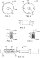
FIG. 5 illustrates a stop of the delivery device ofFIGS. 2-4E . -
FIG. 6 illustrates an alternate stop. -
FIG. 7 is a schematic illustration of the implant ofFIGS. 1A-1C . -
FIGS. 8-9 are perspective views of biasing elements that can be utilized with the delivery device ofFIGS. 2-4E , which are specifically configured for the implant ofFIG. 7 . -
FIG. 10 is a schematic illustration of a capsule assembly including a sheath that can be utilized with the delivery device ofFIGS. 2-4E . -
FIGS. 11A-11E schematically illustrate one method of loading an implant to the delivery device ofFIGS. 2-4E . -
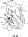
FIG. 12 is a schematic illustration of a method of delivery of an implant to a tricuspid valve with a delivery device of the disclosure. -
FIG. 13 is a schematic illustration of a method of delivery of an implant to a mitral valve with a delivery device of the disclosure. - Specific embodiments of the present disclosure are now described with reference to the figures, wherein like reference numbers indicate identical or functionally similar elements. The terms "distal" and "proximal" are used in the following description with respect to a position or direction relative to the treating clinician. "Distal" or "distally" are a position distant from or in a direction away from the clinician. "Proximal" and "proximally" are a position near or in a direction toward the clinician.
- As referred to herein, implants, stented prostheses, stented prosthetic heart valves or "prosthetic valves" useful with the various systems, devices and methods of the present disclosure may assume a wide variety of configurations. Stented prosthetic heart valves can include, for example, a bioprosthetic heart valve having tissue leaflets or a synthetic heart valve having polymeric, metallic or tissue-engineered leaflets, and can be specifically configured for replacing valves of the human heart. The prosthetic valves and stented prostheses of the present disclosure may be self-expandable, balloon expandable and/or mechanically expandable or combinations thereof. In general terms, the prosthetic valves of the present disclosure include a stent or stent frame having an internal lumen maintaining a valve structure (tissue or synthetic), with the stent frame having an uncompressed, expanded condition or arrangement and collapsible to a compressed condition or arrangement for loading within the delivery device. For example, the stents or stent frames are support structures that comprise a number of struts or wire segments arranged relative to each other to provide a desired compressibility and strength to the prosthetic valve. The struts or wire segments are arranged such that they are capable of self-transitioning from, or being forced from, a compressed or collapsed arrangement to a normal, radially expanded arrangement. The struts or wire segments can be formed from a shape memory material, such as a nickel titanium alloy (e.g., Nitinol). The stent frame can be laser-cut from a single piece of material, or can be assembled from a number of discrete components.
- One non-limiting example of a stented prosthesis or
implant 100 suitable for use with systems and devices of the disclosure is illustrated inFIGS. 1A-1C . In this example, the implant is aprosthetic heart valve 100 including avalve support 110, an anchoringmember 120 attached to thevalve support 110, and aprosthetic valve assembly 150 within thevalve support 110. Referring in particular toFIG. 1B , thevalve support 110 has aninflow region 112 and anoutflow region 114. Theprosthetic valve assembly 150 is arranged within thevalve support 110 to allow blood to flow from theinflow region 112 through the outflow region 114 (arrows BF), but prevent blood from flowing in a direction from theoutflow region 114 through theinflow region 112. - The anchoring
member 120 includes a base 122 attached to theoutflow region 114 of thevalve support 110 and a plurality ofarms 124 projecting laterally outward from thebase 122. The anchoringmember 120 also includes afixation structure 130 extending from thearms 124. Thefixation structure 130 can include afirst portion 132 and asecond portion 134. Thefirst portion 132 of thefixation structure 130, for example, can be an upstream region of thefixation structure 130 that, in a deployed configuration as shown inFIG. 1B , is spaced laterally outward apart from theinflow region 112 of thevalve support 110 by a gap G. Thesecond portion 134 of thefixation structure 130 can be a downstream-most portion of thefixation structure 130. Thefixation structure 130 can be a cylindrical ring (e.g., straight cylinder or conical), and the outer surface of thefixation structure 130 can define an annular engagement surface configured to press outwardly against the native heart valve annulus. Thefixation structure 130 can further include a plurality offixation elements 136 that project radially outward and are inclined toward an upstream direction. Thefixation elements 136, for example, can be barbs, hooks, or other elements that are inclined only in the upstream direction (e.g., a direction extending away from the downstream portion of the implant 100). - The anchoring
member 120 has asmooth bend 140 between thearms 124 and thefixation structure 130. For example, thesecond portion 134 of thefixation structure 130 extends from thearms 124 at thesmooth bend 140. Thearms 124 and thefixation structure 130 can be formed integrally from a continuous strut or support element such that thesmooth bend 140 is a bent portion of the continuous strut. In other examples, thesmooth bend 140 can be a separate component with respect to either thearms 124 or thefixation structure 130. For example, thesmooth bend 140 can be attached to thearms 124 and/or thefixation structure 130 using a weld, adhesive or other technique that forms a smooth connection. Thesmooth bend 140 is configured such that theimplant 100 can be recaptured in a capsule or other container after theimplant 100 has been at least partially deployed. - The
implant 100 can further include afirst sealing member 162 on thevalve support 110 and asecond sealing member 164 on the anchoringmember 120. The first andsecond sealing members first sealing member 162 can cover the interior and/or exterior surfaces of thevalve support 110. Thefirst sealing member 162 is attached to the interior surface of thevalve support 110, and theprosthetic valve assembly 150 is attached to thefirst sealing member 162 and commissure portions of thevalve support 110. Thesecond sealing member 164 is attached to the inner surface of the anchoringmember 120. As a result, the outer annular engagement surface of thefixation structure 130 is not covered by thesecond sealing member 164 so that the outer annular engagement surface of thefixation structure 130 directly contacts the tissue of the native annulus. - The
implant 100 can further include an extension member orbrim 170. Theextension member 170 can be an extension of thesecond sealing member 164, or it can be a separate component attached to thesecond sealing member 164 and/or thefirst portion 132 of thefixation structure 130. Theextension member 170 can be a flexible member that, in a deployed state as shown inFIGS. 1A-1B , flexes relative to thefirst portion 132 of thefixation structure 130. In operation, theextension member 170 guides theimplant 100 during implantation such that the device is located at a desired elevation and centered relative to the native annulus. In some embodiments, one or more components of theextension member 170 can be made of or include a radiopaque material. - As best shown in
FIG. 1A ,valve support 110 defines a first frame (e.g., an inner frame) andfixation structure 130 of the anchoringmember 120 defines a second frame (e.g., an outer frame) that each include a plurality of structural elements. Thefixation structure 130, more specifically, includesstructural elements 137 arranged in diamond-shapedcells 138 that together form at least a substantially cylindrical ring when freely and fully expanded as shown inFIG. 1A . Thestructural elements 137 can be struts or other structural features formed from metal, polymers, or other suitable materials that can self-expand or be expanded by a balloon or other type of mechanical expander. - The
fixation structure 130 can be a generally cylindrical fixation ring having an outwardly facing engagement surface. For example, in the example shown inFIG. 1A , the outer surfaces of thestructural elements 137 define an annular engagement surface configured to press outwardly against the native annulus in the deployed state. In a fully expanded state without any restrictions, thefixation structure 130 is at least substantially parallel to thevalve support 110. However, thefixation structure 130 can flex inwardly (arrow I) in the deployed state when it presses radially outwardly against the inner surface of the native annulus of a heart valve. - The
first sealing member 162 lines the interior surface of thevalve support 110, and thesecond sealing member 164 along the inner surface of thefixation structure 130. Theextension member 170 has a flexible web 172 (e.g., a fabric) and a support member 174 (e.g., metal or polymeric strands) attached to theflexible web 172. Theflexible web 172 can extend from thesecond sealing member 164 without a metal-to-metal connection between thefixation structure 130 and thesupport member 174. For example, theextension member 170 can be a continuation of the material of thesecond sealing member 164. Several embodiments of theextension member 170 are thus a floppy structure that can readily flex with respect to thefixation structure 130. Thesupport member 174 can have a variety of configurations and be made from a variety of materials, such as a double-serpentine structure made from Nitinol. Additional details regarding theimplant 100 can be found inU.S. Pat. Ser. No. 15/643,011 , the disclosure of which is hereby incorporated by reference. - In one example, the
implant 100 has a diameter of 48 mm in the expanded arrangement for delivery within a 35 French capsule or the like. In another example, theimplant 100 has a diameter of 42 mm in the expanded arrangement. - Referring now in addition to
FIGS. 2-3 , which illustrate select components of adelivery device 210 suitable for transcatheter delivery of an implant or prosthesis, such as that ofFIGS. 1A-1C . In general terms, thedelivery device 210 includes ahandle assembly 212 supporting an optionalouter sheath 214 and/or an optionalinner catheter 216. The delivery device includes apiston mount 218, which may be provided within theinner catheter 216. Thepiston mount 218 may support a piston or valve retainer 220 (not visible) within anose cap 236 that may be of any of the type known in the art for releasably retaining an implant compressed within a catheter or the like. Thepiston mount 218 can be an elongated shaft or catheter, for example. Over adistal end 222 ofpiston mount 218, acapsule assembly 230 may be provided that is configured to transition from a loaded arrangement in which thecapsule assembly 230 compressively sheathes the implant to a partially-deployed arrangement in which the capsule assembly is at least partially withdrawn from the implant, to a deployed arrangement in which the implant is fully unsheathed from the capsule assembly so that the implant can expand, releasing the implant from the piston and thedelivery device 210. In various embodiments of the disclosure, thecapsule assembly 230 includes a biasingelement 232 that is a helical compression spring and two ormore retraction wires 234 secured to the biasingelement 232 and which may extend proximally for tensioning to correspondingly pull the biasing element against its bias to unsheathe theimplant 100. At thedistal end 222 of thepiston mount 218, distal to thecapsule assembly 230, anose cap 236 can be provided. In some embodiments, thecapsule assembly 230 may at least partially be positioned within thenose cap 236 in the loaded arrangement (FIG. 2 ) and in other examples, thecapsule assembly 230 may merely abut or otherwise terminate proximal to thenose cap 236 in the loaded arrangement. In non-limiting examples, thenose cap 236 can have a length of about 20 mm (+10 mm/-15 mm), which greatly minimizes a depth in which thedelivery device 210 needs to be deployed into the right ventricle during a transcatheter tricuspid replacement procedure and can reduce anatomical interactions, particularly for small and/or curved right ventricles. In some examples, thenose cap 236 is tapered in a distal direction. - Actuation of the
retraction members 234 can be mechanically accomplished by tensioning theretraction members 234. In another example, theretraction wires 234 can be tensioned using a firstfluid path 240 connected to a firstfluid source 242a as is depicted inFIG. 3 , which can also be configured to recapture theimplant 100 within thecapsule assembly 230. With one hydraulically drivendevice 210, once implant position is finalized within the patient anatomy, fluid from a second inflation device orconnection 242b may be injected into a secondfluid path 244 configured to deploy theimplant 100 by releasing the implant from the piston/valve retainer 220. Fluid may be directed through the secondfluid path 244 into thenose cap 236 to push the nose cap distally into the ventricle, for example, releasing theimplant 100 from thedelivery device 210 and allowing for full deployment of the implant. It is further envisioned that tensioning of theretraction members 234 can be pneumatically or mechanically achieved. - The
capsule assembly 230 can take many forms. Referring in addition toFIGS. 4A-4C , which illustrate thepiston mount 218 supporting an implant (e.g., implant 100) compressed thereon and retained with the piston 220 (not visible). In one example, thecapsule assembly 230 includes the biasingelement 232 being a helical compression spring or the like, that is biased against compression of the biasing element. The plurality of elongated retraction members 234 (generally referenced) are secured to the biasingelement 232 via any suitable method including, but not limited to, welding or crimping. In the illustrated example, fourretraction members 234 are provided although not all retraction members are visible in the drawings. In other examples, between 2-6retraction members 234 are provided. Eachretraction member 234 can be a wire, cord, filament or the like. In one example, theretraction members 234 are approximately equally spaced (+/- 5 degrees). Eachretraction member 234 is secured to the biasingelement 232, at adistal end 238a of the biasingelement 232. In one example, theretraction members 234 are brought together or joined at aproximal end 238b of the biasingelement 232. Theretraction members 234 orelongated member 250 interconnecting theretraction members 234 may extend proximally to thehandle assembly 212 for tensioning to transition thecapsule assembly 230 from the loaded arrangement to the deployed arrangement. Proximal movement and tensioning of theretraction members 234 may correspondingly pull thebiasing element 232 proximally to compress the biasingmember 232 and unsheathe theimplant 100 for expansion and deployment in the process as is generally shown inFIGS. 4A-4E . - In one embodiment, the
piston mount 218 includes astop 252 that is secured to thepiston mount 218 and extends radially therefrom. In one example, thestop 252 is positioned between the biasingelement 232 and theinner catheter 214. Thestop 252 is configured to restrict movement of the biasingelement 232 proximally past thestop 252. In this way, thestop 252 can be made of a metal or rigid polymer, for example. Thestop 252 can be one of many configurations suitable for this purpose. In the example ofFIG. 5 , thestop 252 can include acentral aperture 254 through which thepiston mount 218 can be threaded and/or notches orgrooves 256 within aperiphery surface 258 of thestop 252 in which onerespective retraction member 234 can be positioned. In the example ofFIG. 6 , an alternate stop 252' can include apertures 256' provided through a thickness of the stop through which theretraction members 234 extend as they are tensioned. Alternatively, if theretraction members 234 are joined as shown inFIG. 4A , for example, one or more apertures can be provided in the stop to receive theelongated member 250. It will be understood that the number and placement of notches and apertures can vary depending on the number and orientation of the retraction members provided. - The biasing
element 232 of the disclosure can take many configurations. Generally, the biasingmember 232 can include any structure that biases both thecapsule assembly 230 against compression along a length of the capsule assembly. Therefore, the biasingelement 232 has a natural arrangement in which the biasing element is not exposed to external forces and a compressed arrangement in which the biasing element is compressed against its bias to reduce its length as compared to the natural arrangement. In one example, the biasingelement 232 is a helical compression spring formed of a round wire or a flat wire, in particular that is about 1.5 mm thick (+/-1 mm) so that any cleat/feature protrusion of the implant (typically between 0.5 mm-1.5 mm) would be within the profile of the spring wire of the helical compressionspring biasing element 232 when theimplant 100 is compressed within the biasingelement 232. In one example, the biasingelement 232 has a length of about 25 mm (+/- 5 mm) in the natural arrangement to fully cover the atrial and intra-annular segments of theimplant 100, assuming the implant has approximately a 17 mm intra-annular frame and 10mm brim 170 length in the compressed arrangement. Further wire forming the biasingelement 232 can be radiused to be atraumatic to the anatomy and theimplant 100. - In various examples, a pitch of the wire forming a
biasing element 232 can be set to hold theimplant 100 in a compressed configuration until theimplant 100 is deployed while maintaining gaps 260 (generally referenced inFIG. 4A ) between wraps 262 (generally referenced inFIG. 4A ) to allow for visualization during the procedure and lessens echogenic shadowing under ultrasound as compared to a denser metal capsule design. In one example, thegap 260 betweenwraps 262 is at least equivalent to the width of the wire and up to 10 mm when the biasingelement 232 is in a natural arrangement. In various examples, any metal components of thedelivery device 210, such as the biasingelement 232, can include a dimpled or otherwise textured surface to provide echogenic attributes. The present inventors have found thatgaps 260 formed betweenwraps 262 of the helical compression spring are beneficial in that they provide enhanced visualization of thecapsule assembly 230 as compared to metallic sheath capsules that are more likely to cause artifacts due to their metallic density. - Referring now in addition to
FIGS. 7-9 , the biasingelement 232 can optionally be configured specifically to accommodate attributes of the particular implant to be delivered. For example, if the implant 100 (FIG. 7 ) has a lower outwardly radial force at an area A1 at its proximal end or brim 170 as compared to an area A2 at the distal,outflow region 114 of theimplant 100, a biasingelement 332 can optionally have the corresponding attributes ofFIG. 8 . For example, aproximal end 338a of the biasingelement 332 may have an area A3 having a lower pitch as compared to an area A4 adistal end 338b of the biasing element. As shown inFIG. 9 , an area A5 at aproximal end 438a of biasingelement 432 can be made of a thinner wire as compared to an area A6 at adistal end 438b of the biasingelement 432. Other illustrative examples include a biasing element having varying pitch, filar count, material composition or wire thickness, for example. The respective transition points for changes in pitch, filar count, material composition or wire thickness can correspond to transition points along a length L of theimplant 100 when the implant is in the compressed arrangement. It will be understood that biasing elements of the disclosure can be modified to suit other particular implant forces in a similar manner. Further, it is to be understood that the features of all of the biasing elements disclosed herein are combinable and interchangeable. - Referring now in addition to
FIG. 10 , in various embodiments of the disclosure, thecapsule assembly 230 can optionally include asleeve 270 covering the biasingelement 232. A few non-limiting examples of materials suitable for thesleeve 270 include thermoplastic polyurethanes or polyether block amide 25/30. Thesleeve 270 is beneficial in that it can protect the anatomy fromimplant 100 features until the implant is ready for deployment. In such an embodiment, the biasingelement 232 holds theimplant 100 in a crimped configuration until deployment while maintaininggaps 260 between helical spring wraps 262 to allow for visualization of thecapsule assembly 230 during deployment of theimplant 100. - Referring now in addition to
FIGS. 11A-11E , which illustrate one method of loading an implant (e.g., implant 100) to thedelivery device 210 ofFIGS. 2-4E . In this example, the biasingelement 232 is positioned and compressed such that both distal andproximal ends element 232 are adjacent the nose cap 236 (FIG. 11A ). Then, theimplant 100 is loaded over thepiston mount 218 and crimped to compress the implant using any known technique (FIG. 11B ). In one example, theimplant 100 is loaded onto piston 220 (see also,FIG. 2 ). Next, compression of the biasingelement 232 is released at a controlled rate to allow the biasing element to expand and sheathe theimplant 100. In some methods, at least part of thecapsule assembly 230 remains in thenose cap 236 as the biasingelement 232 is allowed to expand. If theimplant 100 includes cleats, the biasingelement 232 is released in the same direction as the cleats to prevent snagging (FIG. 11C ). Then, theretraction wires 234 can be attached to thedistal end 238a of the biasing element 232 (FIG. 11D ). If applicable,piston 220 can be then be fixed to any implant retention features (e.g., T-bars or the like as known in the art) and thenose cap 236 can be moved proximally to lock theimplant 100 in place, compressed within the capsule assembly 230 (FIG. 11E ). Optionally, thenose cap 236 can be moved proximally to at least partially cover thecapsule assembly 230, including covering one or more of the biasingelement 232, one ormore retraction members 234 and/or anysleeve 270. - Referring in addition now to
FIG. 12 , which schematically illustrates one method of the disclosure. In this example, an implant (e.g., implant 100) is crimped and loaded onto thepiston mount 218 of thedelivery device 210 having thecapsule assembly 230 sheathing theimplant 100 as shown inFIG. 11E . The physician then advances thedelivery device 210 via transcatheter procedure from the interior vena cava IVC into the right atrium RA of a patient's heart. Thenose cap 236 can optionally be connected to steering components, as used in the art, used to steer the nose cap during delivery. Thenose cap 236 can be steered through the tricuspid valve annulus TV until the compressed, loadedimplant 100 is within the tricuspid valve annulus TV. Proper positioning of theimplant 100 in the right atrium RA, proximal to the annulus TV can be confirmed via imaging techniques. Once the physician navigates theimplant 100 to the desired position, theimplant 100 can be transitioned to a partially expanded arrangement by proximally withdrawing and compressing thedistal end 238a of the biasingelement 232 against thestop 252 by tensioning theretraction members 234. Partial, unsheathing of theimplant 100 will cause the proximal end or brim 170 of theimplant 100 to expand outwardly. Optionally, the biasingelement 232 position can be monitored via fluoroscopy. If desired, tension in theretraction members 234 can be lessened to at least partially recapture theimplant 100 within thecapsule assembly 230 for recovery or repositioning of theimplant 100, as desired. When theimplant 100 is in the desired location, thenose cap 236 can be advanced distally via actuation at thehandle assembly 212, thereby freeing theimplant 100 from thepiston 220 anddelivery device 210. Theimplant 100 is then fully seated in the patient's anatomy. Thenose cap 236 andpiston mount 218 can be proximally retracted through theimplant 100 and the delivery system can be withdrawn from the patient in the same manner as delivered. - In methods where the implant is a replacement tricuspid valve and the implantation site is a tricuspid valve, only the nose cap will be deployed into the right ventricle (a length of about 10-20 mm), which is generally a 50-75% reduction in depth that the device deploys into the right ventricle as compared to a traditional sheath capsule, which can have a length of about 41 mm. Due to the reduction in right ventricle deployment depth, devices of the disclosure are suitable for a wider number of patient anatomies. In addition, the smaller, tapered nose cap reduces the risk of anatomical interactions, which are more common with tricuspid valve replacement procedures.
- Referring in addition now to
FIG. 13 , which schematically illustrates another method of the disclosure. In this example, an implant (e.g., implant 100) is crimped and loaded onto thepiston mount 218 of thedelivery device 210 having thecapsule assembly 230 sheathing theimplant 100 as shown inFIG. 11E . The physician then advances thedelivery device 210 via transcatheter procedure into the left atrium LA of a patient's heart. Thenose cap 236 can optionally be connected to steering components, as used in the art, used to steer the nose cap during delivery. Thenose cap 236 can be steered through a mitral valve annulus MV until the compressed, loadedimplant 100 is within the mitral valve annulus MV. Proper positioning of theimplant 100 in the left atrium LA, proximal to the annulus MV can be confirmed via imaging techniques. Once the physician navigates theimplant 100 to the desired position, theimplant 100 can be transitioned to a partially expanded arrangement by proximally withdrawing and compressing thedistal end 238a of the biasingelement 232 against thestop 252 by tensioning theretraction members 234. Partial, unsheathing of theimplant 100 will cause the proximal end or brim 170 of theimplant 100 to expand outwardly. Optionally, the biasingelement 232 position can be monitored via fluoroscopy. If desired, tension in theretraction members 234 can be lessened to at least partially recapture theimplant 100 within thecapsule assembly 230 for recovery or repositioning of theimplant 100, as desired. When theimplant 100 is in the desired location, thenose cap 236 can be advanced distally via actuation at thehandle assembly 212, thereby freeing theimplant 100 from thepiston 220 anddelivery device 210. Theimplant 100 is then fully seated in the patient's anatomy. Thenose cap 236 andpiston mount 218 can be proximally retracted through theimplant 100 and the delivery system can be withdrawn from the patient in the same manner as delivered. In one example, only thenose cap 236 is advanced into the left ventricle LV during the procedure as thecapsule assembly 230 will remain in the left atrium. In one example, the delivery device does not extend further than 30 mm into a left ventricle adjacent the mitral valve during the release of the implant. - It is envisioned that devices and methods of the disclosure are suitable for many types of cardiovascular procedures including mitral valve replacement, tricuspid valve replacement, aortic valve replacement, pulmonic valve replacement, aortic valve replacement, aortic aneurysm stent grafts, peripheral vascular stents. It is further envisioned that devices and methods of the disclosure are suitable for the delivery of gastrointestinal stents, for example.
- It should be understood that various aspects disclosed herein may be combined in different combinations than the combinations specifically presented in the description and accompanying drawings. Each embodiment and each aspect so defined may be combined with any other embodiment or with any other aspect unless clearly indicated to the contrary. It should also be understood that, depending on the example, certain acts or events of any of the processes or methods described herein may be performed in a different sequence, may be added, merged, or left out altogether (e.g., all described acts or events may not be necessary to carry out the techniques). In addition, while certain aspects of this disclosure are described as being performed by a single module or unit for purposes of clarity, it should be understood that the techniques of this disclosure may be performed by a combination of units or modules associated with, for example, a medical device. The words used in the specification are words of description rather than limitation, and it is understood that various changes can be made without departing from the scope of the disclosure.
- Aspects and embodiments of the invention may be defined by the following clauses.
- Clause 1. A delivery device, in particular for transcatheter delivery and deployment of a prosthesis to a heart valve such as the mitral valve or the tricuspid valve, comprising:
- a handle assembly;
- a piston mount having a distal portion, the distal portion including a stop extending radially from and fixed to the distal portion; and
- a capsule assembly including a helical compression spring and a plurality of retraction members secured about a distal end of the compression spring; wherein tensioning of the retraction members compresses the compression spring against the stop.
- Clause 2. The delivery device of clause 1, further comprising a nose cap at least partially positioned distal to the compression spring.
- Clause 3. The delivery device of any one of the preceding clauses, and in particular of clause 2, wherein the delivery device includes a loaded arrangement in which the compression spring is positioned within the nose cap.
- Clause 4. The delivery device of any one of the preceding clauses, and in particular of clause 1, wherein the capsule assembly includes a sleeve.
- Clause 5. The delivery device of any one of the preceding clauses, and in particular of clause 1, wherein the compression spring has a varying pitch along a length of the compression spring.
- Clause 6. The delivery device of any one of the preceding clauses, and in particular of clause 1, wherein the compression spring has a varying thickness along a length of the compression spring.
- Clause 7. The delivery device of any one of the preceding clauses, and in particular of clause 1, wherein the compression spring has a varying filar count along a length of the compression spring.
- Clause 8. The delivery device of any one of the preceding clauses, and in particular of clause 1, wherein the compression spring has a varying material composition along a length of the compression spring.
- Clause 9. The delivery device of any one of the preceding clauses, and in particular of clause 1, further comprising a prosthesis positioned within the capsule assembly.
- Clause 10. The delivery device of any one of the preceding clauses, and in particular of clause 1, wherein the stop includes grooves within a periphery of the stop in which the retraction members are positioned.
- Clause 11. The delivery device of any one of the preceding clauses, and in particular of clause 1, wherein the stop includes an inner aperture to receive the piston mount and includes a plurality of outer apertures in which the retraction members are positioned.
- Clause 12. A method comprising:
providing a delivery device including:- a handle assembly;
- a piston mount connected to the handle assembly and having a distal portion terminating at a nose cap, the distal portion including a stop extending radially from and fixed to the distal portion, and
- a capsule assembly including a biasing element and a plurality of retraction members secured about a distal end of the biasing element; wherein an implant is compressed onto the piston mount and within the capsule assembly;
- delivering the implant to a heart valve with the delivery device;
- tensioning the retraction members to collapse the biasing element against the stop to partially unsheathe the implant; and
- distally advancing the nose cap to fully unsheathe the implant and release the implant from the delivery device.
- Clause 13. The method of clause 12, wherein the heart valve is a tricuspid valve.
- Clause 14. The method of clause 13, wherein the delivery device does not extend further than 30 mm into a right ventricle adjacent the tricuspid valve during the release of the implant.
- Clause 15. The method of clause 13, wherein the capsule assembly remains in a right atrium adjacent the tricuspid valve as the implant is partially and fully unsheathed.
- Clause 16. The method of clause 12, wherein the biasing element is a helical compression spring.
- Clause 17. The method of clause 16, wherein the compression spring has varying thickness along a length of the compression spring.
- Clause 18. The method of clause 16, wherein the compression spring has a varying pitch along a length of the compression spring.
- Clause 19. The method of clause 16, wherein the compression spring has a varying filar count along a length of the compression spring.
- Clause 20. The method of clause 16, wherein the compression spring has a varying material composition along a length of the compression spring.
- Clause 21. The method of clause 16, wherein the capsule assembly includes a sleeve.
- Clause 22. The method of clause 12, wherein the biasing element is positioned underneath the nose cap during the step of delivering the implant.
- Clause 23. The method of clause 12, wherein the heart valve is a mitral valve.
- Clause 24. The method of clause 23, wherein the capsule assembly remains in a left atrium adjacent the mitral valve as the implant is partially and fully unsheathed.
- Clause 25. The method of clause 23, wherein the delivery device does not extend further than 30 mm into a left ventricle adjacent the mitral valve during the release of the implant.
Claims (14)
- A delivery device comprising:a handle assembly;a piston mount having a distal portion, the distal portion including a stop extending radially from and fixed to the distal portion; anda capsule assembly including a helical compression spring and a plurality of retraction members secured about a distal end of the compression spring; wherein tensioning of the retraction members compresses the compression spring against the stop.
- The delivery device of claim 1, further comprising a nose cap at least partially positioned distal to the compression spring.
- The delivery device of claim 1 or 2, wherein the delivery device includes a loaded arrangement in which the compression spring is positioned within the nose cap.
- The delivery device of any one of the preceding claims, wherein the capsule assembly includes a sleeve, in particular for covering the compression spring (232).
- The delivery device of any one of the preceding claims, wherein the compression spring has a varying pitch along a length of the compression spring.
- The delivery device of any one of the preceding claims, wherein the compression spring has a varying thickness along a length of the compression spring.
- The delivery device of any one of the preceding claims, wherein the compression spring has a varying filar count along a length of the compression spring.
- The delivery device of any one of the preceding claims, wherein the compression spring has a varying material composition along a length of the compression spring.
- The delivery device of any one of the preceding claims, further comprising a prosthesis positioned within the capsule assembly.
- The delivery device of any one of the preceding claims, wherein the stop includes grooves within a periphery of the stop in which the retraction members are positioned.
- The delivery device of any one of the preceding claims, wherein the stop includes an inner aperture to receive the piston mount and includes a plurality of outer apertures in which the retraction members are positioned.
- The delivery device of any one of the preceding claims, wherein
the piston mount is connected to the handle assembly and has a distal portion terminating at the nose cap,
wherein the prosthesis is compressed onto the piston mount;wherein tensioning of the retraction members compresses the compression spring against the stop to partially unsheathe the implant; andwherein the nose cap is configured to be distally advanced to fully unsheathe the prosthesis and release the prosthesis from the delivery device. - The delivery device of any one of the preceding claims, further including an inner catheter (214), wherein the stop (252) is positioned between the compression spring (232) and the inner catheter (214); and/or wherein the stop (252) is configured to restrict movement of the compression spring (232) proximally past the stop (252).
- The delivery device of any one of the preceding claims, wherein the piston mount (218) supports a piston (220) within the nose cap (236) for releasably retaining the prosthesis.
Applications Claiming Priority (2)
| Application Number | Priority Date | Filing Date | Title |
|---|---|---|---|
| US202163157202P | 2021-03-05 | 2021-03-05 | |
| US17/590,328 US12336909B2 (en) | 2021-03-05 | 2022-02-01 | Biased capsule for transcatheter valve repair and methods |
Publications (2)
| Publication Number | Publication Date |
|---|---|
| EP4088687A1 true EP4088687A1 (en) | 2022-11-16 |
| EP4088687B1 EP4088687B1 (en) | 2025-06-04 |
Family
ID=80461824
Family Applications (1)
| Application Number | Title | Priority Date | Filing Date |
|---|---|---|---|
| EP22158962.5A Active EP4088687B1 (en) | 2021-03-05 | 2022-02-25 | Biased capsule for transcatheter valve repair |
Country Status (3)
| Country | Link |
|---|---|
| US (1) | US12336909B2 (en) |
| EP (1) | EP4088687B1 (en) |
| CN (1) | CN115006054A (en) |
Citations (3)
| Publication number | Priority date | Publication date | Assignee | Title |
|---|---|---|---|---|
| US20110264203A1 (en) * | 2010-04-27 | 2011-10-27 | Medtronic Vascular, Inc. | Transcatheter Prosthetic Heart Valve Delivery Device With Passive Trigger Release |
| US20130231735A1 (en) * | 2012-03-01 | 2013-09-05 | Foundry Newco Xii, Inc. | Hydraulic delivery systems for prosthetic heart valve devices and associated methods |
| WO2016176610A1 (en) * | 2015-04-30 | 2016-11-03 | Edwards Lifesciences Cardiaq Llc | Replacement mitral valve, delivery system for replacement mitral valve and methods of use |
Family Cites Families (13)
| Publication number | Priority date | Publication date | Assignee | Title |
|---|---|---|---|---|
| US7510572B2 (en) | 2000-09-12 | 2009-03-31 | Shlomo Gabbay | Implantation system for delivery of a heart valve prosthesis |
| US8449594B2 (en) | 2002-11-01 | 2013-05-28 | Marc-Alan Levine | Method and apparatus for caged stent delivery |
| US8273101B2 (en) | 2005-05-25 | 2012-09-25 | Tyco Healthcare Group Lp | System and method for delivering and deploying an occluding device within a vessel |
| US8518098B2 (en) | 2006-02-21 | 2013-08-27 | Cook Medical Technologies Llc | Split sheath deployment system |
| AU2009205739B2 (en) | 2008-01-16 | 2014-09-25 | St. Jude Medical, Inc. | Delivery and retrieval systems for collapsible/expandable prosthetic heart valves |
| US8512401B2 (en) | 2010-04-12 | 2013-08-20 | Medtronic, Inc. | Transcatheter prosthetic heart valve delivery system with funnel recapturing feature and method |
| EP2474287A1 (en) | 2011-01-11 | 2012-07-11 | Symetis Sa | Delivery catheter for stent-valve, and sub-assembly therefor |
| US9901471B2 (en) | 2013-01-30 | 2018-02-27 | Cook Medical Technologies Llc | Spring assisted medical device deployment assembly |
| EP2881141B1 (en) | 2013-12-04 | 2016-06-01 | Sorin CRM SAS | Implantable intracardiac capsule on a thin wall, in particular the septal wall |
| US10376364B2 (en) | 2015-11-10 | 2019-08-13 | Edwards Lifesciences Corporation | Implant delivery capsule |
| AU2017290667B2 (en) | 2016-06-29 | 2019-06-06 | Boston Scientific Scimed, Inc. | Stent delivery system |
| US10575950B2 (en) | 2017-04-18 | 2020-03-03 | Twelve, Inc. | Hydraulic systems for delivering prosthetic heart valve devices and associated methods |
| US10786352B2 (en) | 2017-07-06 | 2020-09-29 | Twelve, Inc. | Prosthetic heart valve devices and associated systems and methods |
-
2022
- 2022-02-01 US US17/590,328 patent/US12336909B2/en active Active
- 2022-02-25 EP EP22158962.5A patent/EP4088687B1/en active Active
- 2022-03-04 CN CN202210208269.3A patent/CN115006054A/en active Pending
Patent Citations (3)
| Publication number | Priority date | Publication date | Assignee | Title |
|---|---|---|---|---|
| US20110264203A1 (en) * | 2010-04-27 | 2011-10-27 | Medtronic Vascular, Inc. | Transcatheter Prosthetic Heart Valve Delivery Device With Passive Trigger Release |
| US20130231735A1 (en) * | 2012-03-01 | 2013-09-05 | Foundry Newco Xii, Inc. | Hydraulic delivery systems for prosthetic heart valve devices and associated methods |
| WO2016176610A1 (en) * | 2015-04-30 | 2016-11-03 | Edwards Lifesciences Cardiaq Llc | Replacement mitral valve, delivery system for replacement mitral valve and methods of use |
Also Published As
| Publication number | Publication date |
|---|---|
| EP4088687B1 (en) | 2025-06-04 |
| CN115006054A (en) | 2022-09-06 |
| US20220280293A1 (en) | 2022-09-08 |
| US12336909B2 (en) | 2025-06-24 |
Similar Documents
| Publication | Publication Date | Title |
|---|---|---|
| US12186184B2 (en) | Docking stations for transcatheter valves | |
| US11446141B2 (en) | Prosthetic heart valve having non-cylindrical frame | |
| US20200375739A1 (en) | Devices and methods for transcatheter valve loading and implantation | |
| WO2019040364A1 (en) | Sealing member for prosthetic heart valve | |
| WO2021173531A1 (en) | Valve retention supplemented with a wire hoop | |
| CN117426904A (en) | Prosthetic heart valve and prosthetic heart valve delivery assembly | |
| US20220265422A1 (en) | Transcatheter valve replacement delivery device with engageable capsule portions and methods | |
| US12594159B2 (en) | Sealing member for prosthetic heart valve | |
| US12263106B2 (en) | Transcatheter implant delivery device and methods of implant loading and delivery | |
| US12268602B2 (en) | Telescoping capsule assembly for transcatheter valve repair and methods | |
| US20250099243A1 (en) | Systems for transcatheter valve replacement and methods | |
| US20250049569A1 (en) | Transcatheter valve delivery system with improved loading and deployment | |
| EP4088687B1 (en) | Biased capsule for transcatheter valve repair | |
| US12263083B2 (en) | Systems for transcatheter prosthesis delivery and methods | |
| US20250295490A1 (en) | Transcatheter delivery device having flexible capsule | |
| US20260137512A1 (en) | Docking station with improved sealing skirt | |
| WO2025049266A1 (en) | Prosthetic mitral valve for treating patients with small annulus dimensions | |
| HK40018073A (en) | Docking stations for transcatheter valves | |
| HK40018073B (en) | Docking stations for transcatheter valves |
Legal Events
| Date | Code | Title | Description |
|---|---|---|---|
| PUAI | Public reference made under article 153(3) epc to a published international application that has entered the european phase |
Free format text: ORIGINAL CODE: 0009012 |
|
| STAA | Information on the status of an ep patent application or granted ep patent |
Free format text: STATUS: REQUEST FOR EXAMINATION WAS MADE |
|
| 17P | Request for examination filed |
Effective date: 20220225 |
|
| AK | Designated contracting states |
Kind code of ref document: A1 Designated state(s): AL AT BE BG CH CY CZ DE DK EE ES FI FR GB GR HR HU IE IS IT LI LT LU LV MC MK MT NL NO PL PT RO RS SE SI SK SM TR |
|
| GRAP | Despatch of communication of intention to grant a patent |
Free format text: ORIGINAL CODE: EPIDOSNIGR1 |
|
| STAA | Information on the status of an ep patent application or granted ep patent |
Free format text: STATUS: GRANT OF PATENT IS INTENDED |
|
| INTG | Intention to grant announced |
Effective date: 20250103 |
|
| RIN1 | Information on inventor provided before grant (corrected) |
Inventor name: MULVIHILL, ISABEL H. Inventor name: DOTTI, ALEXANDRA C. Inventor name: FRANK, CHRISTINA E. Inventor name: GUPTE, KIMAYA N. |
|
| GRAS | Grant fee paid |
Free format text: ORIGINAL CODE: EPIDOSNIGR3 |
|
| GRAA | (expected) grant |
Free format text: ORIGINAL CODE: 0009210 |
|
| STAA | Information on the status of an ep patent application or granted ep patent |
Free format text: STATUS: THE PATENT HAS BEEN GRANTED |
|
| AK | Designated contracting states |
Kind code of ref document: B1 Designated state(s): AL AT BE BG CH CY CZ DE DK EE ES FI FR GB GR HR HU IE IS IT LI LT LU LV MC MK MT NL NO PL PT RO RS SE SI SK SM TR |
|
| REG | Reference to a national code |
Ref country code: GB Ref legal event code: FG4D |
|
| REG | Reference to a national code |
Ref country code: CH Ref legal event code: EP |
|
| REG | Reference to a national code |
Ref country code: DE Ref legal event code: R096 Ref document number: 602022015334 Country of ref document: DE |
|
| REG | Reference to a national code |
Ref country code: IE Ref legal event code: FG4D |
|
| REG | Reference to a national code |
Ref country code: NL Ref legal event code: MP Effective date: 20250604 |
|
| PG25 | Lapsed in a contracting state [announced via postgrant information from national office to epo] |
Ref country code: FI Free format text: LAPSE BECAUSE OF FAILURE TO SUBMIT A TRANSLATION OF THE DESCRIPTION OR TO PAY THE FEE WITHIN THE PRESCRIBED TIME-LIMIT Effective date: 20250604 Ref country code: ES Free format text: LAPSE BECAUSE OF FAILURE TO SUBMIT A TRANSLATION OF THE DESCRIPTION OR TO PAY THE FEE WITHIN THE PRESCRIBED TIME-LIMIT Effective date: 20250604 |
|
| REG | Reference to a national code |
Ref country code: LT Ref legal event code: MG9D |
|
| PG25 | Lapsed in a contracting state [announced via postgrant information from national office to epo] |
Ref country code: NO Free format text: LAPSE BECAUSE OF FAILURE TO SUBMIT A TRANSLATION OF THE DESCRIPTION OR TO PAY THE FEE WITHIN THE PRESCRIBED TIME-LIMIT Effective date: 20250904 Ref country code: GR Free format text: LAPSE BECAUSE OF FAILURE TO SUBMIT A TRANSLATION OF THE DESCRIPTION OR TO PAY THE FEE WITHIN THE PRESCRIBED TIME-LIMIT Effective date: 20250905 |
|
| PG25 | Lapsed in a contracting state [announced via postgrant information from national office to epo] |
Ref country code: PL Free format text: LAPSE BECAUSE OF FAILURE TO SUBMIT A TRANSLATION OF THE DESCRIPTION OR TO PAY THE FEE WITHIN THE PRESCRIBED TIME-LIMIT Effective date: 20250604 |
|
| PG25 | Lapsed in a contracting state [announced via postgrant information from national office to epo] |
Ref country code: BG Free format text: LAPSE BECAUSE OF FAILURE TO SUBMIT A TRANSLATION OF THE DESCRIPTION OR TO PAY THE FEE WITHIN THE PRESCRIBED TIME-LIMIT Effective date: 20250604 |
|
| PG25 | Lapsed in a contracting state [announced via postgrant information from national office to epo] |
Ref country code: HR Free format text: LAPSE BECAUSE OF FAILURE TO SUBMIT A TRANSLATION OF THE DESCRIPTION OR TO PAY THE FEE WITHIN THE PRESCRIBED TIME-LIMIT Effective date: 20250604 |
|
| PG25 | Lapsed in a contracting state [announced via postgrant information from national office to epo] |
Ref country code: RS Free format text: LAPSE BECAUSE OF FAILURE TO SUBMIT A TRANSLATION OF THE DESCRIPTION OR TO PAY THE FEE WITHIN THE PRESCRIBED TIME-LIMIT Effective date: 20250904 |
|
| PG25 | Lapsed in a contracting state [announced via postgrant information from national office to epo] |
Ref country code: LV Free format text: LAPSE BECAUSE OF FAILURE TO SUBMIT A TRANSLATION OF THE DESCRIPTION OR TO PAY THE FEE WITHIN THE PRESCRIBED TIME-LIMIT Effective date: 20250604 |
|
| PG25 | Lapsed in a contracting state [announced via postgrant information from national office to epo] |
Ref country code: NL Free format text: LAPSE BECAUSE OF FAILURE TO SUBMIT A TRANSLATION OF THE DESCRIPTION OR TO PAY THE FEE WITHIN THE PRESCRIBED TIME-LIMIT Effective date: 20250604 |
|
| PG25 | Lapsed in a contracting state [announced via postgrant information from national office to epo] |
Ref country code: PT Free format text: LAPSE BECAUSE OF FAILURE TO SUBMIT A TRANSLATION OF THE DESCRIPTION OR TO PAY THE FEE WITHIN THE PRESCRIBED TIME-LIMIT Effective date: 20251006 |
|
| REG | Reference to a national code |
Ref country code: AT Ref legal event code: MK05 Ref document number: 1799657 Country of ref document: AT Kind code of ref document: T Effective date: 20250604 |
|
| PG25 | Lapsed in a contracting state [announced via postgrant information from national office to epo] |
Ref country code: IS Free format text: LAPSE BECAUSE OF FAILURE TO SUBMIT A TRANSLATION OF THE DESCRIPTION OR TO PAY THE FEE WITHIN THE PRESCRIBED TIME-LIMIT Effective date: 20251004 |
|
| PG25 | Lapsed in a contracting state [announced via postgrant information from national office to epo] |
Ref country code: AT Free format text: LAPSE BECAUSE OF FAILURE TO SUBMIT A TRANSLATION OF THE DESCRIPTION OR TO PAY THE FEE WITHIN THE PRESCRIBED TIME-LIMIT Effective date: 20250604 Ref country code: SM Free format text: LAPSE BECAUSE OF FAILURE TO SUBMIT A TRANSLATION OF THE DESCRIPTION OR TO PAY THE FEE WITHIN THE PRESCRIBED TIME-LIMIT Effective date: 20250604 |
|
| PG25 | Lapsed in a contracting state [announced via postgrant information from national office to epo] |
Ref country code: CZ Free format text: LAPSE BECAUSE OF FAILURE TO SUBMIT A TRANSLATION OF THE DESCRIPTION OR TO PAY THE FEE WITHIN THE PRESCRIBED TIME-LIMIT Effective date: 20250604 |
|
| PG25 | Lapsed in a contracting state [announced via postgrant information from national office to epo] |
Ref country code: EE Free format text: LAPSE BECAUSE OF FAILURE TO SUBMIT A TRANSLATION OF THE DESCRIPTION OR TO PAY THE FEE WITHIN THE PRESCRIBED TIME-LIMIT Effective date: 20250604 |
|
| PG25 | Lapsed in a contracting state [announced via postgrant information from national office to epo] |
Ref country code: SK Free format text: LAPSE BECAUSE OF FAILURE TO SUBMIT A TRANSLATION OF THE DESCRIPTION OR TO PAY THE FEE WITHIN THE PRESCRIBED TIME-LIMIT Effective date: 20250604 |
|
| PG25 | Lapsed in a contracting state [announced via postgrant information from national office to epo] |
Ref country code: IT Free format text: LAPSE BECAUSE OF FAILURE TO SUBMIT A TRANSLATION OF THE DESCRIPTION OR TO PAY THE FEE WITHIN THE PRESCRIBED TIME-LIMIT Effective date: 20250604 |
|
| REG | Reference to a national code |
Ref country code: DE Ref legal event code: R097 Ref document number: 602022015334 Country of ref document: DE |
|
| PLBE | No opposition filed within time limit |
Free format text: ORIGINAL CODE: 0009261 |
|
| STAA | Information on the status of an ep patent application or granted ep patent |
Free format text: STATUS: NO OPPOSITION FILED WITHIN TIME LIMIT |
|
| PG25 | Lapsed in a contracting state [announced via postgrant information from national office to epo] |
Ref country code: DK Free format text: LAPSE BECAUSE OF FAILURE TO SUBMIT A TRANSLATION OF THE DESCRIPTION OR TO PAY THE FEE WITHIN THE PRESCRIBED TIME-LIMIT Effective date: 20250604 |
|
| PGFP | Annual fee paid to national office [announced via postgrant information from national office to epo] |
Ref country code: DE Payment date: 20260121 Year of fee payment: 5 |
|
| REG | Reference to a national code |
Ref country code: CH Ref legal event code: L10 Free format text: ST27 STATUS EVENT CODE: U-0-0-L10-L00 (AS PROVIDED BY THE NATIONAL OFFICE) Effective date: 20260416 |
|
| 26N | No opposition filed |
Effective date: 20260305 |