EP4088635B1 - Device for the retractability of the flexible hose of central vacuum systems - Google Patents
Device for the retractability of the flexible hose of central vacuum systems Download PDFInfo
- Publication number
- EP4088635B1 EP4088635B1 EP22172330.7A EP22172330A EP4088635B1 EP 4088635 B1 EP4088635 B1 EP 4088635B1 EP 22172330 A EP22172330 A EP 22172330A EP 4088635 B1 EP4088635 B1 EP 4088635B1
- Authority
- EP
- European Patent Office
- Prior art keywords
- flexible hose
- housing
- tubing
- box
- hose
- Prior art date
- Legal status (The legal status is an assumption and is not a legal conclusion. Google has not performed a legal analysis and makes no representation as to the accuracy of the status listed.)
- Active
Links
Images



Classifications
-
- A—HUMAN NECESSITIES
- A47—FURNITURE; DOMESTIC ARTICLES OR APPLIANCES; COFFEE MILLS; SPICE MILLS; SUCTION CLEANERS IN GENERAL
- A47L—DOMESTIC WASHING OR CLEANING; SUCTION CLEANERS IN GENERAL
- A47L5/00—Structural features of suction cleaners
- A47L5/12—Structural features of suction cleaners with power-driven air-pumps or air-compressors, e.g. driven by motor vehicle engine vacuum
- A47L5/22—Structural features of suction cleaners with power-driven air-pumps or air-compressors, e.g. driven by motor vehicle engine vacuum with rotary fans
- A47L5/38—Built-in suction cleaner installations, i.e. with fixed tube system to which, at different stations, hoses can be connected
-
- A—HUMAN NECESSITIES
- A47—FURNITURE; DOMESTIC ARTICLES OR APPLIANCES; COFFEE MILLS; SPICE MILLS; SUCTION CLEANERS IN GENERAL
- A47L—DOMESTIC WASHING OR CLEANING; SUCTION CLEANERS IN GENERAL
- A47L9/00—Details or accessories of suction cleaners, e.g. mechanical means for controlling the suction or for effecting pulsating action; Storing devices specially adapted to suction cleaners or parts thereof; Carrying-vehicles specially adapted for suction cleaners
- A47L9/24—Hoses or pipes; Hose or pipe couplings
- A47L9/248—Parts, details or accessories of hoses or pipes
Definitions
- the present invention relates to a device for the retractability of the flexible hose of central vacuum systems.
- these systems are constituted by a central vacuum unit located in a service room or in a sheltered outdoor place and connected, by means of in-wall tubing, to one or more vacuum inlets into which the flexible hose of adapted cleaning accessories, similar to those of portable vacuum cleaners, is coupled when needed.
- the aim of the present invention is to overcome the drawbacks of the prior art.
- the solution proposed with the present invention which is as simple as it is unusual and most of all advantageous, both from the practical standpoint and from the economic standpoint, consists in summary in extending the rigid tubing of the system with an additional fraction which, in addition to having the adequate cross-section and the length that are sufficient to accommodate the flexible hose inside it, is entirely contained within an adapted rigid enclosure which is shaped so that it can be placeable easily wherever necessary.
- Figures 1 and 2 show a device comprising a housing 1, having a substantially parallelepiped shape, which is flush-mounted in a dividing wall of the room in which to operate with the cleaning accessories inserted in the flexible hose 6 extracted as needed.
- Figure 2 shows that at least two faces of the housing 1, the ones that are flush with the masonry wall, are provided with a metallic mesh (or equivalent) for the grip of the plaster which, similar to that of housings for retracting sliding doors and for other similar situations, allows the completion of the housing with the same finish as the wall in which it is flush-mounted.
- the housing in question might be intended for an "exposed" installation and therefore may arrive for installation already aesthetically finished to be fixed against a wall and proximate to the tubing 5 of the system to which the tubing 2 of the housing 1 is to be connected.
- the housing 1 can be made of metallic material, although the adoption of any other material with equivalent characteristics is not excluded.
- a central vacuum system which comprises a control unit which, via the tubing 5, is stably connected to the tubing 2 since the housing 1 is installed.
- one end of the tubing 2 communicates with the box 3, from which the flexible hose 6 is to be extracted when needed, while the other end, being designed to be connected to the in-wall tubing 5 that arrives from the vacuum apparatus, according to the embodiment of Figure 1 , ends with a connector of the type of a branch 4 for connection to the tubing 5 that originates from one of the three possible directions of which two, 5a and 5b, are along the wall and one, 5c, is under the floor.
- the rigid tubing 2 regardless of whether it is connected to the tubing 5 of the system with a branch 4 or with any other connector, has a narrowing of the terminal portion 2a ( Figure 8 ) against which the thicker end 6a (shoulder) of the retractable hose 6 stops when a portion of said hose ( Figures 6 and 7 ) on which it is possible to act manually for extraction remains inside the box 3, such extraction being also necessarily limited by the arrival of said thicker end 6a (shoulder) against the rounded mouth 30 of the hole for access of the flexible hose 6 to the box ( Figure 9 ).
- Figures 7 and 9 to which Figures 3 and 5 also refer, is termed two-sided here since it allows the extraction and use of the flexible hose 6 in each of the two rooms separated by the wall in which the housing 1 is flush-mounted.
- the installation of a two-sided housing of the type shown in Figure 3 has the advantage of being executable by orienting in each instance the outlet of the end 2a of the tubing 2 toward the direction of arrival of the tubing 5 of the central system to which it is to be connected.
- the materials used, as well as the contingent shapes and dimensions may be any according to the requirements and to the state of the art.
Landscapes
- Engineering & Computer Science (AREA)
- Mechanical Engineering (AREA)
- Electric Vacuum Cleaner (AREA)
Description
- The present invention relates to a device for the retractability of the flexible hose of central vacuum systems.
- It is known that central vacuum systems, where it is possible to install them, are preferred over portable vacuum cleaners since the latter recirculate back into the spaces in which they operate the aspirated air, which is never filtered perfectly.
- In summary, these systems are constituted by a central vacuum unit located in a service room or in a sheltered outdoor place and connected, by means of in-wall tubing, to one or more vacuum inlets into which the flexible hose of adapted cleaning accessories, similar to those of portable vacuum cleaners, is coupled when needed.
- Some central systems, already appreciated for the external expulsion of the aspirated air and of the microdust entrained by it, are appreciated even more if, at each end of use, it is not necessary to roll up and store the flexible hose which, in this case, is retracted by the suction of the central unit into the rigid tubing of the system and kept therein until it is used again.
- Obviously, these are systems that are provided for this purpose right from the outset, since in order to be able to obtain the retractability of the flexible hose the rigid tubing must have a cross-section and a layout that allows the aspirated hose to travel along it easily and without hindrance.
-
US 2011/041282 ,US 2007/174991 andWO 01/24677 - Since it is complicated and excessively onerous to intervene in existing central systems in order to replace their tubing, which is almost always in-wall, with a tubing that allows retractability of the flexible hose in the described manner, the aim of the present invention is to overcome the drawbacks of the prior art.
- The above aim and other objects that will become more apparent hereinafter are achieved by a device as claimed in
claim 1. - The solution proposed with the present invention, which is as simple as it is unusual and most of all advantageous, both from the practical standpoint and from the economic standpoint, consists in summary in extending the rigid tubing of the system with an additional fraction which, in addition to having the adequate cross-section and the length that are sufficient to accommodate the flexible hose inside it, is entirely contained within an adapted rigid enclosure which is shaped so that it can be placeable easily wherever necessary.
- Further characteristics and advantages of the invention will become better apparent from the detailed description of a preferred, but not exclusive, embodiment of the device according to the present invention, illustrated by way of non-limiting example in the accompanying drawings, wherein:
-
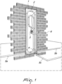
Figures 1 and2 show the rendering of the installation of the invention as an integration of a conventional central system; -
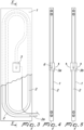
Figure 3 is a cutout of the front view of the invention; -
Figure 4 is a view of a first embodiment of the invention, taken along the vertical sectional plane X-X ofFigure 3 ; -
Figure 5 is a view of a second embodiment of the invention, termed two-sided, taken along the vertical sectional plane X-X ofFigure 3 ; -
Figure 6 is a detail view of a detail ofFigure 4 related to theextraction box 3a of theflexible hose 6; -
Figure 7 is a detail view of a detail ofFigure 5 related to theextraction box 3b of theflexible hose 6; -
Figure 8 is a detail view of a detail ofFigure 3 related to thenarrowing 2a of thetubing 2 and the stopping of theflexible hose 6 retracted inside; -
Figure 9 is a view of the extraction and stopping of the flexible hose after lifting one of the two cover doors of thebox 3b which in this case is already installed and complete withfinishing plaster 11. - With reference to the drawings,
Figures 1 and2 show a device comprising ahousing 1, having a substantially parallelepiped shape, which is flush-mounted in a dividing wall of the room in which to operate with the cleaning accessories inserted in theflexible hose 6 extracted as needed. - In particular,
Figure 2 shows that at least two faces of thehousing 1, the ones that are flush with the masonry wall, are provided with a metallic mesh (or equivalent) for the grip of the plaster which, similar to that of housings for retracting sliding doors and for other similar situations, allows the completion of the housing with the same finish as the wall in which it is flush-mounted. However, it is not excluded that the housing in question might be intended for an "exposed" installation and therefore may arrive for installation already aesthetically finished to be fixed against a wall and proximate to the tubing 5 of the system to which thetubing 2 of thehousing 1 is to be connected. - Preferably, the
housing 1 can be made of metallic material, although the adoption of any other material with equivalent characteristics is not excluded. - In fact, inside the
housing 1, both if it is to be flush-mounted or if it is to remain visible, there is thetubing 2 into which to accommodate the entireflexible hose 6 when drawn by the suction applied by a central vacuum system (which comprises a control unit) which, via the tubing 5, is stably connected to thetubing 2 since thehousing 1 is installed. - It should be noted that one end of the
tubing 2 communicates with thebox 3, from which theflexible hose 6 is to be extracted when needed, while the other end, being designed to be connected to the in-wall tubing 5 that arrives from the vacuum apparatus, according to the embodiment ofFigure 1 , ends with a connector of the type of abranch 4 for connection to the tubing 5 that originates from one of the three possible directions of which two, 5a and 5b, are along the wall and one, 5c, is under the floor. - The
rigid tubing 2, regardless of whether it is connected to the tubing 5 of the system with abranch 4 or with any other connector, has a narrowing of theterminal portion 2a (Figure 8 ) against which thethicker end 6a (shoulder) of theretractable hose 6 stops when a portion of said hose (Figures 6 and 7 ) on which it is possible to act manually for extraction remains inside thebox 3, such extraction being also necessarily limited by the arrival of saidthicker end 6a (shoulder) against therounded mouth 30 of the hole for access of theflexible hose 6 to the box (Figure 9 ). - All this independently of the fact that it is a
box 3a with just thecover door 7 or abox 3b with thecover doors more levers 10 which, pivoted in succession (Figure 7 ), are arranged aligned (Figure 9 ) when one of the two cover doors is stopped open, thus forcing the other one to remain closed until the former is closed (mechanical interlocking of the twocover doors 8 and 9). - The embodiment of
Figures 7 and9 , to whichFigures 3 and 5 also refer, is termed two-sided here since it allows the extraction and use of theflexible hose 6 in each of the two rooms separated by the wall in which thehousing 1 is flush-mounted. - Furthermore, the installation of a two-sided housing of the type shown in
Figure 3 has the advantage of being executable by orienting in each instance the outlet of theend 2a of thetubing 2 toward the direction of arrival of the tubing 5 of the central system to which it is to be connected. - In practice it has been found that the device according to the invention fully achieves the set aim and objects.
- The device thus conceived is susceptible of numerous modifications and variations, all of which are within the scope of the appended claims.
- Moreover, all the details may be substituted by other, technically equivalent elements.
- In practice, the materials used, as well as the contingent shapes and dimensions, may be any according to the requirements and to the state of the art.
- The disclosures in
Italian Utility Model Application No. 202021000002579 - Where technical features mentioned in any claim are followed by reference signs, those reference signs have been included for the sole purpose of increasing the intelligibility of the claims and accordingly, such reference signs do not have any limiting effect on the interpretation of each element identified by way of example by such reference signs.
Claims (4)
- A device for retracting of a flexible hose of a central vacuum system, comprising at least one housing (1), having a substantially parallelepiped shape, configured for an arrangement chosen between flush-mounted in a wall and exposed, said housing (1) comprises a rigid tubing (2), associated with a vacuum apparatus by means of a tubing (5), which has a cross-section and a length which are suitable to accommodate internally a flexible hose (6) that can be extracted from said housing (1) by pulling from the terminal end of said hose (6) that faces outward through an opening of said housing (1), said hose (6) being retractable into said rigid tubing (2) by virtue of the action of the negative pressure established by the suction applied by said apparatus, wherein one end of the rigid tubing (2) ends in a box (3) which can be accessed from the outside of the housing (1) and from which the flexible hose (6) is extracted when needed while the other end ends with a connector of the type of a branch (4) which allows the connection of the rigid tubing (2) to the tubing (5) of the system that arrives from the vacuum apparatus, and characterized in that the box (3) is provided with two cover doors (8 and 9) to allow the extraction and use of the flexible hose (6) in each of the two spaces separated by the wall in which the housing (1) is flush-mounted.
- The device according to claim 1, wherein a rear end (6a) of the flexible hose (6) has an external thicker shoulder region which produces its stopping upon extraction, against a rounded mouth (30) of a hole for access to the box (3a, 3b), and upon retraction, against a narrowing (2a) of the terminal portion of the tubing (2) of the housing (1).
- The device according to claim 2, wherein when automatic retraction, due to suction, of the flexible hose (6) into the box (3a, 3b) ceases, a portion of said hose (6) continues to protrude on which one acts manually after opening an adapted cover door (7, 8, 9) for complete retraction.
- The device according to claim 1, wherein the cover doors (8 and 9) of the extraction box (3b) comprise interlocking means for their mutual coupling, which are provided with at least one set of at least two levers (10) which, hinged in succession, are arranged aligned when one of the two cover doors (8, 9) is in the open configuration, blocking the other cover door in the closed configuration.
Applications Claiming Priority (1)
| Application Number | Priority Date | Filing Date | Title |
|---|---|---|---|
| IT202021000002579U IT202100002579U1 (en) | 2021-05-14 | 2021-05-14 | BOX EQUIPPED FOR THE RETRACTILITY OF THE FLEXIBLE HOSE OF CENTRALIZED VACUUM CLEANER SYSTEMS. |
Publications (3)
| Publication Number | Publication Date |
|---|---|
| EP4088635A1 EP4088635A1 (en) | 2022-11-16 |
| EP4088635C0 EP4088635C0 (en) | 2024-04-24 |
| EP4088635B1 true EP4088635B1 (en) | 2024-04-24 |
Family
ID=83594618
Family Applications (1)
| Application Number | Title | Priority Date | Filing Date |
|---|---|---|---|
| EP22172330.7A Active EP4088635B1 (en) | 2021-05-14 | 2022-05-09 | Device for the retractability of the flexible hose of central vacuum systems |
Country Status (2)
| Country | Link |
|---|---|
| EP (1) | EP4088635B1 (en) |
| IT (1) | IT202100002579U1 (en) |
Family Cites Families (3)
| Publication number | Priority date | Publication date | Assignee | Title |
|---|---|---|---|---|
| AU7855400A (en) * | 1999-10-07 | 2001-05-10 | Gary Drivstuen | Retractable hose central vacuum cleaning system |
| US8001650B2 (en) * | 2006-02-01 | 2011-08-23 | Jerry Trotter | Automatic debris collector for a central vacuum system |
| US8590098B2 (en) * | 2008-01-29 | 2013-11-26 | H-P Products, Inc. | Vacuum hose storage system |
-
2021
- 2021-05-14 IT IT202021000002579U patent/IT202100002579U1/en unknown
-
2022
- 2022-05-09 EP EP22172330.7A patent/EP4088635B1/en active Active
Also Published As
| Publication number | Publication date |
|---|---|
| EP4088635A1 (en) | 2022-11-16 |
| IT202100002579U1 (en) | 2022-11-14 |
| EP4088635C0 (en) | 2024-04-24 |
Similar Documents
| Publication | Publication Date | Title |
|---|---|---|
| US3377756A (en) | Demountable building partition construction | |
| US2708833A (en) | Mobile air conditioning means for window openings | |
| KR19990045394A (en) | Discharge port for connecting the vacuum hose to the centralized vacuum cleaner | |
| BR0213266B1 (en) | device for mounting a central vacuum cleaning system. | |
| US4484692A (en) | Wall mounted housing for cable television components | |
| US20040149475A1 (en) | Cable entry box | |
| US20040250371A1 (en) | Pipe coupler for in-wall central vacuuming system | |
| US11715938B2 (en) | Mounting device with fastener receiving structure | |
| WO2003023926A9 (en) | Expandable structured wiring box | |
| EP4088635A1 (en) | Device for the retractability of the flexible hose of central vacuum systems | |
| EP2083224A2 (en) | Ceiling type air conditioner with filter cleaning mechanism | |
| US9523511B2 (en) | Indoor unit of air-conditioning apparatus | |
| CN109826537A (en) | A kind of fire-fighting door structure for pushing and pulling and being opened flat combination and open | |
| KR102285484B1 (en) | Cable molde | |
| EP3521543A1 (en) | Box for external flush-mounted roller blind | |
| CN211776924U (en) | Wardrobe door plate with ventilation function | |
| KR20190041835A (en) | the variable type of Wall | |
| CN117248663A (en) | A movable partition wall structure and its partition method | |
| TW312866B (en) | ||
| KR100749723B1 (en) | Bidirectional integrated wire protection duct for apartments embedded in the wall | |
| KR100999471B1 (en) | Wire outlet box | |
| CN219921928U (en) | Novel fire hydrant box | |
| KR20240080959A (en) | House terminal box of apartment | |
| KR100427847B1 (en) | Slide Mobile Type Concent | |
| CN215407904U (en) | Forbidden protector of door |
Legal Events
| Date | Code | Title | Description |
|---|---|---|---|
| PUAI | Public reference made under article 153(3) epc to a published international application that has entered the european phase |
Free format text: ORIGINAL CODE: 0009012 |
|
| STAA | Information on the status of an ep patent application or granted ep patent |
Free format text: STATUS: THE APPLICATION HAS BEEN PUBLISHED |
|
| AK | Designated contracting states |
Kind code of ref document: A1 Designated state(s): AL AT BE BG CH CY CZ DE DK EE ES FI FR GB GR HR HU IE IS IT LI LT LU LV MC MK MT NL NO PL PT RO RS SE SI SK SM TR |
|
| STAA | Information on the status of an ep patent application or granted ep patent |
Free format text: STATUS: REQUEST FOR EXAMINATION WAS MADE |
|
| RAP1 | Party data changed (applicant data changed or rights of an application transferred) |
Owner name: VMC GROUP S.R.L. |
|
| 17P | Request for examination filed |
Effective date: 20230331 |
|
| RBV | Designated contracting states (corrected) |
Designated state(s): AL AT BE BG CH CY CZ DE DK EE ES FI FR GB GR HR HU IE IS IT LI LT LU LV MC MK MT NL NO PL PT RO RS SE SI SK SM TR |
|
| P01 | Opt-out of the competence of the unified patent court (upc) registered |
Effective date: 20230527 |
|
| GRAP | Despatch of communication of intention to grant a patent |
Free format text: ORIGINAL CODE: EPIDOSNIGR1 |
|
| STAA | Information on the status of an ep patent application or granted ep patent |
Free format text: STATUS: GRANT OF PATENT IS INTENDED |
|
| INTG | Intention to grant announced |
Effective date: 20231115 |
|
| GRAS | Grant fee paid |
Free format text: ORIGINAL CODE: EPIDOSNIGR3 |
|
| GRAA | (expected) grant |
Free format text: ORIGINAL CODE: 0009210 |
|
| STAA | Information on the status of an ep patent application or granted ep patent |
Free format text: STATUS: THE PATENT HAS BEEN GRANTED |
|
| AK | Designated contracting states |
Kind code of ref document: B1 Designated state(s): AL AT BE BG CH CY CZ DE DK EE ES FI FR GB GR HR HU IE IS IT LI LT LU LV MC MK MT NL NO PL PT RO RS SE SI SK SM TR |
|
| REG | Reference to a national code |
Ref country code: GB Ref legal event code: FG4D |
|
| REG | Reference to a national code |
Ref country code: CH Ref legal event code: EP |
|
| REG | Reference to a national code |
Ref country code: DE Ref legal event code: R096 Ref document number: 602022003006 Country of ref document: DE |
|
| REG | Reference to a national code |
Ref country code: IE Ref legal event code: FG4D |
|
| U01 | Request for unitary effect filed |
Effective date: 20240522 |
|
| P04 | Withdrawal of opt-out of the competence of the unified patent court (upc) registered |
Effective date: 20240528 |
|
| U07 | Unitary effect registered |
Designated state(s): AT BE BG DE DK EE FI FR IT LT LU LV MT NL PT SE SI Effective date: 20240529 |
|
| U20 | Renewal fee for the european patent with unitary effect paid |
Year of fee payment: 3 Effective date: 20240530 |
|
| PG25 | Lapsed in a contracting state [announced via postgrant information from national office to epo] |
Ref country code: IS Free format text: LAPSE BECAUSE OF FAILURE TO SUBMIT A TRANSLATION OF THE DESCRIPTION OR TO PAY THE FEE WITHIN THE PRESCRIBED TIME-LIMIT Effective date: 20240824 |
|
| PG25 | Lapsed in a contracting state [announced via postgrant information from national office to epo] |
Ref country code: HR Free format text: LAPSE BECAUSE OF FAILURE TO SUBMIT A TRANSLATION OF THE DESCRIPTION OR TO PAY THE FEE WITHIN THE PRESCRIBED TIME-LIMIT Effective date: 20240424 |
|
| PG25 | Lapsed in a contracting state [announced via postgrant information from national office to epo] |
Ref country code: ES Free format text: LAPSE BECAUSE OF FAILURE TO SUBMIT A TRANSLATION OF THE DESCRIPTION OR TO PAY THE FEE WITHIN THE PRESCRIBED TIME-LIMIT Effective date: 20240424 |
|
| PG25 | Lapsed in a contracting state [announced via postgrant information from national office to epo] |
Ref country code: PL Free format text: LAPSE BECAUSE OF FAILURE TO SUBMIT A TRANSLATION OF THE DESCRIPTION OR TO PAY THE FEE WITHIN THE PRESCRIBED TIME-LIMIT Effective date: 20240424 |
|
| PG25 | Lapsed in a contracting state [announced via postgrant information from national office to epo] |
Ref country code: PL Free format text: LAPSE BECAUSE OF FAILURE TO SUBMIT A TRANSLATION OF THE DESCRIPTION OR TO PAY THE FEE WITHIN THE PRESCRIBED TIME-LIMIT Effective date: 20240424 Ref country code: NO Free format text: LAPSE BECAUSE OF FAILURE TO SUBMIT A TRANSLATION OF THE DESCRIPTION OR TO PAY THE FEE WITHIN THE PRESCRIBED TIME-LIMIT Effective date: 20240724 Ref country code: IS Free format text: LAPSE BECAUSE OF FAILURE TO SUBMIT A TRANSLATION OF THE DESCRIPTION OR TO PAY THE FEE WITHIN THE PRESCRIBED TIME-LIMIT Effective date: 20240824 Ref country code: HR Free format text: LAPSE BECAUSE OF FAILURE TO SUBMIT A TRANSLATION OF THE DESCRIPTION OR TO PAY THE FEE WITHIN THE PRESCRIBED TIME-LIMIT Effective date: 20240424 Ref country code: ES Free format text: LAPSE BECAUSE OF FAILURE TO SUBMIT A TRANSLATION OF THE DESCRIPTION OR TO PAY THE FEE WITHIN THE PRESCRIBED TIME-LIMIT Effective date: 20240424 Ref country code: RS Free format text: LAPSE BECAUSE OF FAILURE TO SUBMIT A TRANSLATION OF THE DESCRIPTION OR TO PAY THE FEE WITHIN THE PRESCRIBED TIME-LIMIT Effective date: 20240724 |
|
| P05 | Withdrawal of opt-out of the competence of the unified patent court (upc) changed |
Free format text: CASE NUMBER: APP_31220/2024 Effective date: 20240529 |
|
| PG25 | Lapsed in a contracting state [announced via postgrant information from national office to epo] |
Ref country code: CZ Free format text: LAPSE BECAUSE OF FAILURE TO SUBMIT A TRANSLATION OF THE DESCRIPTION OR TO PAY THE FEE WITHIN THE PRESCRIBED TIME-LIMIT Effective date: 20240424 |
|
| PG25 | Lapsed in a contracting state [announced via postgrant information from national office to epo] |
Ref country code: SK Free format text: LAPSE BECAUSE OF FAILURE TO SUBMIT A TRANSLATION OF THE DESCRIPTION OR TO PAY THE FEE WITHIN THE PRESCRIBED TIME-LIMIT Effective date: 20240424 Ref country code: RO Free format text: LAPSE BECAUSE OF FAILURE TO SUBMIT A TRANSLATION OF THE DESCRIPTION OR TO PAY THE FEE WITHIN THE PRESCRIBED TIME-LIMIT Effective date: 20240424 |
|
| REG | Reference to a national code |
Ref country code: DE Ref legal event code: R097 Ref document number: 602022003006 Country of ref document: DE |
|
| PG25 | Lapsed in a contracting state [announced via postgrant information from national office to epo] |
Ref country code: SM Free format text: LAPSE BECAUSE OF FAILURE TO SUBMIT A TRANSLATION OF THE DESCRIPTION OR TO PAY THE FEE WITHIN THE PRESCRIBED TIME-LIMIT Effective date: 20240424 |
|
| PG25 | Lapsed in a contracting state [announced via postgrant information from national office to epo] |
Ref country code: SM Free format text: LAPSE BECAUSE OF FAILURE TO SUBMIT A TRANSLATION OF THE DESCRIPTION OR TO PAY THE FEE WITHIN THE PRESCRIBED TIME-LIMIT Effective date: 20240424 Ref country code: SK Free format text: LAPSE BECAUSE OF FAILURE TO SUBMIT A TRANSLATION OF THE DESCRIPTION OR TO PAY THE FEE WITHIN THE PRESCRIBED TIME-LIMIT Effective date: 20240424 Ref country code: RO Free format text: LAPSE BECAUSE OF FAILURE TO SUBMIT A TRANSLATION OF THE DESCRIPTION OR TO PAY THE FEE WITHIN THE PRESCRIBED TIME-LIMIT Effective date: 20240424 Ref country code: CZ Free format text: LAPSE BECAUSE OF FAILURE TO SUBMIT A TRANSLATION OF THE DESCRIPTION OR TO PAY THE FEE WITHIN THE PRESCRIBED TIME-LIMIT Effective date: 20240424 Ref country code: MC Free format text: LAPSE BECAUSE OF FAILURE TO SUBMIT A TRANSLATION OF THE DESCRIPTION OR TO PAY THE FEE WITHIN THE PRESCRIBED TIME-LIMIT Effective date: 20240424 |
|
| PLBE | No opposition filed within time limit |
Free format text: ORIGINAL CODE: 0009261 |
|
| STAA | Information on the status of an ep patent application or granted ep patent |
Free format text: STATUS: NO OPPOSITION FILED WITHIN TIME LIMIT |
|
| 26N | No opposition filed |
Effective date: 20250127 |
|
| PG25 | Lapsed in a contracting state [announced via postgrant information from national office to epo] |
Ref country code: IE Free format text: LAPSE BECAUSE OF NON-PAYMENT OF DUE FEES Effective date: 20240509 |
|
| U20 | Renewal fee for the european patent with unitary effect paid |
Year of fee payment: 4 Effective date: 20250520 |
|
| PG25 | Lapsed in a contracting state [announced via postgrant information from national office to epo] |
Ref country code: CY Free format text: LAPSE BECAUSE OF FAILURE TO SUBMIT A TRANSLATION OF THE DESCRIPTION OR TO PAY THE FEE WITHIN THE PRESCRIBED TIME-LIMIT; INVALID AB INITIO Effective date: 20220509 |
|
| PG25 | Lapsed in a contracting state [announced via postgrant information from national office to epo] |
Ref country code: HU Free format text: LAPSE BECAUSE OF FAILURE TO SUBMIT A TRANSLATION OF THE DESCRIPTION OR TO PAY THE FEE WITHIN THE PRESCRIBED TIME-LIMIT; INVALID AB INITIO Effective date: 20220509 |
|
| PG25 | Lapsed in a contracting state [announced via postgrant information from national office to epo] |
Ref country code: GR Free format text: LAPSE BECAUSE OF FAILURE TO SUBMIT A TRANSLATION OF THE DESCRIPTION OR TO PAY THE FEE WITHIN THE PRESCRIBED TIME-LIMIT; INVALID AB INITIO Effective date: 20220509 |
|
| REG | Reference to a national code |
Ref country code: CH Ref legal event code: H13 Free format text: ST27 STATUS EVENT CODE: U-0-0-H10-H13 (AS PROVIDED BY THE NATIONAL OFFICE) Effective date: 20251223 |
|
| PG25 | Lapsed in a contracting state [announced via postgrant information from national office to epo] |
Ref country code: CH Free format text: LAPSE BECAUSE OF NON-PAYMENT OF DUE FEES Effective date: 20250531 |