EP4088610A1 - Sole and shoe - Google Patents
Sole and shoe Download PDFInfo
- Publication number
- EP4088610A1 EP4088610A1 EP22168169.5A EP22168169A EP4088610A1 EP 4088610 A1 EP4088610 A1 EP 4088610A1 EP 22168169 A EP22168169 A EP 22168169A EP 4088610 A1 EP4088610 A1 EP 4088610A1
- Authority
- EP
- European Patent Office
- Prior art keywords
- plate
- foot
- sole
- opening
- support portion
- Prior art date
- Legal status (The legal status is an assumption and is not a legal conclusion. Google has not performed a legal analysis and makes no representation as to the accuracy of the status listed.)
- Withdrawn
Links
- 210000002683 foot Anatomy 0.000 claims abstract description 146
- 210000004744 fore-foot Anatomy 0.000 claims abstract description 26
- 210000000452 mid-foot Anatomy 0.000 claims abstract description 20
- 210000000431 third toe Anatomy 0.000 claims abstract description 16
- 210000000453 second toe Anatomy 0.000 claims abstract description 10
- 210000000454 fifth toe Anatomy 0.000 claims description 27
- 210000001503 joint Anatomy 0.000 claims description 4
- 230000003247 decreasing effect Effects 0.000 claims 4
- 230000004048 modification Effects 0.000 description 86
- 238000012986 modification Methods 0.000 description 86
- 239000000463 material Substances 0.000 description 19
- 210000001255 hallux Anatomy 0.000 description 14
- 239000000835 fiber Substances 0.000 description 13
- 230000007423 decrease Effects 0.000 description 11
- 210000001872 metatarsal bone Anatomy 0.000 description 11
- 210000003371 toe Anatomy 0.000 description 10
- 230000000694 effects Effects 0.000 description 7
- 229920005989 resin Polymers 0.000 description 7
- 239000004744 fabric Substances 0.000 description 6
- 239000011347 resin Substances 0.000 description 6
- 230000005540 biological transmission Effects 0.000 description 5
- 230000037237 body shape Effects 0.000 description 5
- 229920000049 Carbon (fiber) Polymers 0.000 description 3
- 239000007767 bonding agent Substances 0.000 description 3
- 239000004917 carbon fiber Substances 0.000 description 3
- 238000003780 insertion Methods 0.000 description 3
- 230000037431 insertion Effects 0.000 description 3
- VNWKTOKETHGBQD-UHFFFAOYSA-N methane Chemical compound C VNWKTOKETHGBQD-UHFFFAOYSA-N 0.000 description 3
- 238000000034 method Methods 0.000 description 3
- 238000004080 punching Methods 0.000 description 3
- 238000003466 welding Methods 0.000 description 3
- 239000004433 Thermoplastic polyurethane Substances 0.000 description 2
- 238000005452 bending Methods 0.000 description 2
- 229920000728 polyester Polymers 0.000 description 2
- 239000002952 polymeric resin Substances 0.000 description 2
- 229920003002 synthetic resin Polymers 0.000 description 2
- 229920002725 thermoplastic elastomer Polymers 0.000 description 2
- 229920002803 thermoplastic polyurethane Polymers 0.000 description 2
- 230000007704 transition Effects 0.000 description 2
- 239000002759 woven fabric Substances 0.000 description 2
- 238000012935 Averaging Methods 0.000 description 1
- ZOXJGFHDIHLPTG-UHFFFAOYSA-N Boron Chemical compound [B] ZOXJGFHDIHLPTG-UHFFFAOYSA-N 0.000 description 1
- 210000003423 ankle Anatomy 0.000 description 1
- 229920006231 aramid fiber Polymers 0.000 description 1
- 229910052796 boron Inorganic materials 0.000 description 1
- 210000000459 calcaneus Anatomy 0.000 description 1
- 210000000455 fourth toe Anatomy 0.000 description 1
- 239000003365 glass fiber Substances 0.000 description 1
- 230000012447 hatching Effects 0.000 description 1
- 239000002649 leather substitute Substances 0.000 description 1
- 229920001778 nylon Polymers 0.000 description 1
- 230000035699 permeability Effects 0.000 description 1
- 229920002577 polybenzoxazole Polymers 0.000 description 1
- 239000000057 synthetic resin Substances 0.000 description 1
- 210000004233 talus Anatomy 0.000 description 1
- 229920000785 ultra high molecular weight polyethylene Polymers 0.000 description 1
Images









Classifications
-
- A—HUMAN NECESSITIES
- A43—FOOTWEAR
- A43B—CHARACTERISTIC FEATURES OF FOOTWEAR; PARTS OF FOOTWEAR
- A43B13/00—Soles; Sole-and-heel integral units
- A43B13/14—Soles; Sole-and-heel integral units characterised by the constructive form
- A43B13/16—Pieced soles
-
- A—HUMAN NECESSITIES
- A43—FOOTWEAR
- A43B—CHARACTERISTIC FEATURES OF FOOTWEAR; PARTS OF FOOTWEAR
- A43B13/00—Soles; Sole-and-heel integral units
- A43B13/02—Soles; Sole-and-heel integral units characterised by the material
- A43B13/026—Composites, e.g. carbon fibre or aramid fibre; the sole, one or more sole layers or sole part being made of a composite
-
- A—HUMAN NECESSITIES
- A43—FOOTWEAR
- A43B—CHARACTERISTIC FEATURES OF FOOTWEAR; PARTS OF FOOTWEAR
- A43B13/00—Soles; Sole-and-heel integral units
- A43B13/02—Soles; Sole-and-heel integral units characterised by the material
- A43B13/12—Soles with several layers of different materials
- A43B13/125—Soles with several layers of different materials characterised by the midsole or middle layer
- A43B13/127—Soles with several layers of different materials characterised by the midsole or middle layer the midsole being multilayer
-
- A—HUMAN NECESSITIES
- A43—FOOTWEAR
- A43B—CHARACTERISTIC FEATURES OF FOOTWEAR; PARTS OF FOOTWEAR
- A43B13/00—Soles; Sole-and-heel integral units
- A43B13/14—Soles; Sole-and-heel integral units characterised by the constructive form
- A43B13/18—Resilient soles
- A43B13/181—Resiliency achieved by the structure of the sole
-
- A—HUMAN NECESSITIES
- A43—FOOTWEAR
- A43B—CHARACTERISTIC FEATURES OF FOOTWEAR; PARTS OF FOOTWEAR
- A43B13/00—Soles; Sole-and-heel integral units
- A43B13/38—Built-in insoles joined to uppers during the manufacturing process, e.g. structural insoles; Insoles glued to shoes during the manufacturing process
- A43B13/41—Built-in insoles joined to uppers during the manufacturing process, e.g. structural insoles; Insoles glued to shoes during the manufacturing process combined with heel stiffener, toe stiffener, or shank stiffener
Definitions
- the present invention relates to a sole including a plate and a shoe.
- a sole of a conventional shoe As a sole of a conventional shoe, a sole provided with a hard plate is known.
- the plate has a function of increasing the rigidity of the sole to prevent the shoe from bending and increase forward thrust. When a wearer runs on a paved road, the function of the plate can be maximized to enhance the running efficiency.
- JP 2018-534028 A discloses a technique in which an opening is provided in a portion corresponding to a forefoot of a foot.
- the present invention has been made in view of the above, and an object of the present invention is to obtain a sole that prevents movement of the toes of a foot from being hindered by a plate while securing functions by the plate of increasing thrust and of reducing transmission of upthrust to the foot.
- a sole connecting a forefoot support portion supporting a forefoot of a foot, a midfoot support portion supporting a midfoot of the foot, and a rearfoot support portion supporting a rearfoot of the foot in this order from a front side the sole includes: an outsole provided with a ground contact surface; a midsole disposed above the outsole; and a plate disposed above the outsole and on at least the forefoot support portion and the midfoot support portion, the plate having hardness higher than hardness of the midsole.
- the plate is provided with an opening at a position corresponding to a region at least from a proximal phalanx of a second toe to a proximal phalanx of a third toe, the plate has an outer edge including a medial-foot-side end edge positioned on a medial foot side from the opening and a lateral-foot-side end edge positioned on a lateral foot side from the opening, and at least one of the medial-foot-side end edge and the lateral-foot-side end edge is formed alternately with a projection projecting away from a shoe center axis in a foot width direction of the sole and a recess recessed to be closer to the shoe center axis in a foot width direction of the sole.
- FIG. 1 is a plan view schematically illustrating a shoe 1 according to a first embodiment of the present invention overlapped on a skeleton model of a foot.
- FIG. 1 only the shoe 1 for a left foot is illustrated. Since the shoe 1 has a left-right symmetrical structure for a left foot and a right foot, only the shoe 1 for a left foot is described in the present embodiment, and the description of the shoe 1 for a right foot is omitted.
- a direction in which a shoe center axis C, which is a perpendicular line passing through the center of a sole 3 in a plan view of the shoe 1, extends is referred to as a front-rear direction
- a direction orthogonal to the front-rear direction in a plan view of the shoe 1 is referred to as a foot width direction.
- a direction directed from the end on the side where the sole 3 supporting the rearfoot of a foot is positioned toward the end on the side where the sole 3 supporting the forefoot of the foot is positioned is referred to as a front side
- a direction directed from the end on the side where the sole 3 supporting the forefoot of the foot is positioned toward the end on the side where the sole 3 supporting the rearfoot of the foot is positioned is referred to as a rear side.
- a median side of a foot in the anatomical position is referred to as a medial foot side
- the side opposite to the median side of the foot in the anatomical position is referred to as a lateral foot side. That is, the side closer to the median line in the anatomical position is referred to as the medial foot side, and the side farther from the median line in the anatomical position is referred to as the lateral foot side.
- a height direction means a direction orthogonal to both the front-rear direction and the foot width direction unless otherwise specified.
- a thickness means a dimension in the thickness direction of the sole 3 unless otherwise specified.
- the foot of a human body mainly includes a cuneiform Ba, a cuboid Bb, a navicular Bc, a talus Bd, a calcaneus Be, a metatarsal Bf, a proximal phalanx Bg, a middle phalanx Bh, and a distal phalanx Bi.
- the joints of a foot include a DIP joint Ja that is a distal interphalangeal joint, a PIP joint Jb that is a proximal interphalangeal joint, an MP joint Jc that is a metatarsopharangeal joint, a Lisfranc joint Jd, and a Chopart joint Je.
- a forefoot of a foot refers to a part positioned anterior to the MP joint Jc.
- a midfoot of the foot refers to a part from the MP joint Jc to the Chopart joint Je.
- a rearfoot of the foot refers to a part positioned posterior to the Chopart joint Je.
- the sole 3 includes a forefoot support portion R1 that supports the forefoot of a foot of a wearer with a standard body shape, a midfoot support portion R2 that supports the midfoot of a foot of a wearer with a standard body shape, and a rearfoot support portion R3 that supports the rearfoot portion of a foot of a wearer with a standard body shape.
- the forefoot support portion R1, the midfoot support portion R2, and the rearfoot support portion R3 are connected in this order from the front side of the sole 3 in the front-rear direction.
- a line along the foot width direction passing through a position corresponding to about 36% of the dimension of the sole 3 from the front end of the sole 3 in the front-rear direction is defined as a first boundary line S1
- a line along the foot width direction passing through a position corresponding to about 70% of the dimension of the sole 3 from the front end of the sole 3 in the front-rear direction is defined as a second boundary line S2.
- the first boundary line S1 is a line roughly along the MP joint Jc of a wearer with a standard body shape
- the second boundary line S2 is a line roughly along the Chopart joint Je of a wearer with a standard body shape.
- the forefoot support portion R1 is positioned in front of the first boundary line S1.
- the midfoot support portion R2 is positioned between the first boundary line S1 and the second boundary line S2.
- the rearfoot support portion R3 is positioned behind the second boundary line S2.
- FIG. 2 is a side view of the shoe 1 on the lateral foot side according to the first embodiment.
- the shoe 1 is preferably a running shoe for trail but may be a running shoe for road, other sports shoe, and walking shoe.
- the shoe 1 includes an upper 2 and a sole 3.
- the upper 2 is positioned above the sole 3.
- the upper 2 includes an upper body 20 and a shoe tongue 21.
- the upper body 20 covers a part on the instep side of a foot.
- a foot insertion opening 20a for inserting a foot of a wearer and an opening 20b communicating with the foot insertion opening 20a and extending from the foot insertion opening 20a to the front side are formed.
- a plurality of string passing portions 20c spaced apart from each other in the front-rear direction is provided on both side edges of the opening 20b in the foot width direction.
- FIG. 2 illustrates only the string passing portions 20c provided on the side edge on the lateral foot side of the opening 20b.
- a shoelace (not illustrated) is alternately passed through the string passing portions 20c provided on the side edge on the lateral foot side of the opening 20b and the string passing portions 20c provided on the side edge on the medial foot side.
- the upper 2 including the shoe tongue 21 and the shoe lace is described as an example, but the upper 2 may have a monosock structure in which a portion corresponding to the shoe tongue 21 is integrated with an ankle portion of the upper body 20.
- a hook-and-loop fastener may be used instead of the shoelace to bring the upper body 20 into close contact with a foot. If a hook-and-loop fastener is used to bring the upper body 20 into close contact with a foot, the string passing portions 20c are not formed in the upper body 20.
- the shoe tongue 21 is a member for protecting the instep of a wearer.
- the shoe tongue 21 covers the opening 20b inside the upper body 20.
- the shoe tongue 21 is fixed to the upper body 20 by stitching, welding, bonding, or a combination thereof.
- the material of the upper body 20 and the shoe tongue 21 is, for example, woven fabric, knitted fabric, synthetic leather, or resin.
- the material of the upper body 20 and the shoe tongue 21 is preferably a double raschel warp knitted fabric knitted with polyester yarn. Note that the material of the upper body 20 and the shoe tongue 21 is not limited to those exemplified.
- FIG. 3 is a cross-sectional view taken along line III-III in FIG. 1 .
- the sole 3 is positioned below the upper 2.
- the sole 3 covers the sole of a wearer.
- the shape of the toe portion of the sole 3 is a shape warping up toward the front side, that is, a so-called tow spring shape.
- the sole 3 includes an outsole 30 provided with a ground contact surface 30a, a midsole 31 disposed above the outsole 30, and a plate 4.
- the sole 3 is fixed to the upper 2 by stitching, welding, bonding, or a combination thereof.
- the lower surface of the outsole 30 serves as the ground contact surface 30a to contact on the ground.
- the midsole 31 is positioned on the upper surface of the outsole 30 and has a cushioning property.
- the sole 3 includes an inner sole (not illustrated) that covers the lower opening of the upper body 20.
- the inner sole is fixed to the upper surface of the midsole 31 by bonding or welding.
- the inner sole is fixed to the lower edge of the upper body 20 by stitching.
- the sole 3 may have a structure in which the inner sole is omitted.
- the shoe 1 may include an insole. If the shoe 1 includes an insole, the insole is placed on the sole 3 inside the upper 2.
- the plate 4 has hardness higher than hardness of the midsole 31.
- the material of the plate 4 is, for example, short carbon fiber reinforced material, fiber reinforced resin, non-fiber reinforced resin, or fiber fabric material.
- the flexural modulus of the short carbon fiber reinforced material used as the material of the plate 4 is desirably 5 Gpa to 15 Gpa.
- the fiber reinforced resin is, for example, carbon fiber, glass fiber, aramid fiber, Dyneema fiber, Zylon fiber, or boron fiber. If the material of the plate 4 is the fiber reinforced resin, the rigidity and the load support effect of the plate 4 can be enhanced.
- the non-fiber reinforced resin is, for example, polymer resin.
- the polymer resin is, for example, thermoplastic polyurethane (TPU) or thermoplastic elastomer (TPA). If the material of the plate 4 is the non-fiber reinforced resin, the rigidity of the plate 4 is reduced, which allows the toes to easily move.
- the fiber fabric material is, for example, knitted fabric or woven fabric of polyester fiber, nylon fiber, or the like. If the material of the plate 4 is the fiber fabric material, impact at the time of landing can be mitigated, and the weight of the plate 4 can be reduced.
- the plate 4 is disposed above the outsole 30. In the present embodiment, the plate 4 is disposed between the outsole 30 and the midsole 31. As illustrated in FIG. 1 , the plate 4 is disposed from the forefoot support portion R1 to the midfoot support portion R2 in the present embodiment. The plate 4 is disposed from a position corresponding to the distal phalanx Bi to a position corresponding to the vicinity of the Lisfranc joint Jd in the front-rear direction. The plate 4 is disposed from a position corresponding to the first toe to a position corresponding to the fifth toe in the foot width direction. In FIG. 1 , the plate 4 is disposed below the midsole 31 and cannot be seen, but the plate 4 is illustrated by a solid line and dot hatching for easy understanding.
- the plate 4 is provided with an opening 40a passing through in the thickness direction of the sole 3.
- the shape of the opening 40a in plan view may be a polygon, such as a triangle or a quadrangle, but is preferable to have a shape in which the corners illustrated in FIG. 1 are rounded in order to mitigate stress concentration at the corners.
- the shape of the opening 40a in plan view is not limited to the illustrated example and may be a shape having no corner, such as a circle or an ellipse.
- the opening 40a is provided at a position corresponding to a region from the distal phalanx Bi, the middle phalanx Bh, the proximal phalanx Bg, and the metatarsal Bf of the second toe to the middle phalanx Bh, the proximal phalanx Bg, and the metatarsal Bf of the fourth toe.
- the opening 40a is not limited to the illustrated range and may be provided at a position corresponding to a region at least from the proximal phalanx Bg of the second toe to the proximal phalanx Bg of the third toe.
- a portion along the shoe center axis C is referred to as a shoe center.
- the plate 4 is provided with the opening 40a in such a manner as to include a circle P whose center is positioned at 32% from the front end of the shoe center and whose diameter is 10% of the dimension of the shoe center. That is, the opening 40a is only required to be provided in such a manner as to include at least the circle P.
- the outer edge of the plate 4 includes a front end edge 40b positioned in front of the opening 40a, a medial-foot-side end edge 40c positioned on the medial foot side from the opening 40a, a lateral-foot-side end edge 40d positioned on the lateral foot side from the opening 40a, and a rear end edge 40e positioned behind the opening 40a.
- the front end edge 40b extends in a curved shape to project to the front side.
- the medial-foot-side end edge 40c extends from the end portion on the medial foot side of the front end edge 40b toward the rear side.
- the medial-foot-side end edge 40c extends in a curved shape to project to the medial foot side.
- the lateral-foot-side end edge 40d extends from the end portion on the lateral foot side of the front end edge 40b toward the rear side.
- the lateral-foot-side end edge 40d is formed alternately with a projection 40f projecting away from the shoe center axis C in the foot width direction of the sole 3 and a recess 40g recessed to be closer to the shoe center axis C in the foot width direction of the sole 3.
- the number of projections 40f is not particularly limited but is three in the present embodiment.
- the number of recesses 40g is not particularly limited but is four in the present embodiment.
- One of the recesses 40g is preferably disposed at a position corresponding to the DIP joint Ja of the fifth toe.
- the second recess 40g from the front side is disposed at the position corresponding to the DIP joint Ja of the fifth toe.
- the depth of each recess 40g is preferably less than 20% of the width along the foot width direction of the portion of the plate 4 corresponding to each recess 40g, or 8 mm to 10 mm from the lateral-foot-side end edge 40d toward the medial foot side.
- the rear end edge 40e connects the rear end portions of the medial-foot-side end edge 40c and the lateral-foot-side end edge 40d.
- the rear end edge 40e is formed with an inclined portion 40h inclined to be positioned forward from the lateral foot side toward the medial foot side, and a protrusion 40i continuous with an end portion of the inclined portion 40h on the medial foot side and protruding toward the rear side.
- a constricted portion 40j recessed toward the front side is formed.
- the rear end edge 40e extends from a position corresponding to the metatarsal Bf of the fifth toe to a position corresponding to the metatarsal Bf of the first toe.
- the inclined portion 40h is formed from the end portion of the rear end edge 40e on the lateral foot side to the medial foot side from the center in the foot width direction.
- the inclined portion 40h is disposed from a position corresponding to the metatarsal Bf of the fifth toe to a position corresponding to the metatarsal Bf of the second toe.
- the protrusion 40i is formed at the end portion of the rear end edge 40e on the medial foot side.
- the protrusion 40i is disposed from a position corresponding to the metatarsal Bf of the second toe to a position corresponding to the metatarsal Bf of the first toe.
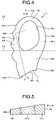
- FIG. 4 is a plan view of the plate 4 according to the first embodiment.
- FIG. 5 is a cross-sectional view taken along line V-V in FIG. 4 .
- a line along the foot width direction passing through a front-most portion of the opening 40a illustrated in FIG. 4 is defined as a front boundary line S3, and a line along the foot width direction passing through a rear-most portion of the opening 40a is defined as a rear boundary line S4.
- the plate 4 includes a tiptoe region 40k positioned in front of the opening 40a, a medial foot side region 40m positioned on the medial foot side from the opening 40a, a lateral foot side region 40n positioned on the lateral foot side from the opening 40a, and a rear region 40o positioned behind the opening 40a.
- the tiptoe region 40k is positioned in front of the front boundary line S3.
- the medial foot side region 40m is a region positioned on the medial foot side from the opening 40a and between the front boundary line S3 and the rear boundary line S4.
- the lateral foot side region 40n is a region positioned on the lateral foot side from the opening 40a and between the front boundary line S3 and the rear boundary line S4.
- the rear region 40o is positioned behind the rear boundary line S4.
- the thickness of the plate 4 in the thickness direction of the sole 3 decreases from the rear side toward the front side.
- the plate 4 is formed in an inclined shape that gradually becomes thinner from the rear side toward the front side.
- the thickness at and near the rear end edge 40e is the thickest in the plate 4.
- the thickness at and near the front end edge 40b is the thinnest in the plate 4.
- the thickness of the lateral foot side region 40n is thinner than the thickness at and near the rear end edge 40e and thicker than the thickness at and near the front end edge 40b.
- the thickness of the tiptoe region 40k, the thickness of the rear region 40o, and the thickness of the lateral foot side region 40n in the thickness direction of the sole 3 are set to satisfy a relationship of b>c>a, where a is the thickness of the tiptoe region 40k, b is the thickness of the rear region 40o, and c is the thickness of the lateral foot side region 40n.
- the thickness a of the tiptoe region 40k, the thickness b of the rear region 40o, and the thickness c of the lateral foot side region 40n each mean an average thickness obtained by measuring the thickness at three points arbitrarily selected in the respective regions 40k, 40n, and 40o and averaging the measured values at the three points.
- the thickness c of the lateral foot side region 40n is set to, for example, an intermediate thickness between the thickness a of the tiptoe region 40k and the thickness b of the rear region 40o.
- the sole 3 includes the plate 4 disposed above the outsole 30 and on at least the forefoot support portion R1 and the midfoot support portion R2, and the plate 4 has hardness higher than hardness of the midsole 31. Accordingly, it is possible to increase the rigidity of the sole 3 to prevent the shoe 1 from bending and increase forward thrust.
- the plate 4 is provided with the opening 40a as illustrated in FIG. 1 . Accordingly, it is possible to reduce transmission of upthrust to the foot at the time of landing on an uneven ground and to reduce the load on the foot.
- the opening 40a at a position corresponding to a region from the proximal phalanx Bg of the second toe and the proximal phalanx Bg of the third toe, where the upthrust is most likely to be felt, it is possible for a wearer to less feel the upthrust.
- the outer edge of the plate 4 includes the medial-foot-side end edge 40c positioned on the medial foot side from the opening 40a and the lateral-foot-side end edge 40d positioned on the lateral foot side from the opening 40a.
- the lateral-foot-side end edge 40d is formed alternately with the projection 40f projecting away from the shoe center axis C in the foot width direction of the sole 3 and the recess 40g recessed to be closer to the shoe center axis C in the foot width direction of the sole 3.
- each recess 40g By providing the recesses 40g at a position corresponding to the toes, it is possible to prevent movement of the toes from being hindered by the plate 4. Thus, when a wearer goes down a slope on an uneven ground, the wearer easily moves the toes to take quick turns and fine steps. Note that, by setting the depth of each recess 40g to less than 20% of the width along the foot width direction of the portion of the plate 4 corresponding to each recess 40g, or to 8 mm to 10 mm from the lateral-foot-side end edge 40d toward the medial foot side, it is possible to reduce decrease in the rigidity of the sole 3 due to the provision of the recesses 40g and to secure forward thrust.
- a recess 40g is disposed at a position corresponding to at least the DIP joint Ja of the fifth toe, which allows the DIP joint Ja of the fifth toe to easily move.
- the wearer when a wearer goes down a slope on an uneven ground, the wearer easily moves the DIP joint Ja of the fifth toe to take quick turns and fine steps.
- the opening 40a has a rounded shape in plan view, and stress concentration at the edges of the opening 40a is prevented, which reduces the risk of damaging the plate 4.
- the outer edge of the plate 4 includes the rear end edge 40e positioned behind the opening 40a, and the rear end edge 40e is formed with the inclined portion 40h inclined to be positioned forward from the lateral foot side toward the medial foot side. This makes it easy to incline a foot around the horizontal axis along the front-rear direction.
- the protrusion 40i continuous with the end portion of the inclined portion 40h on the medial foot side and protruding toward the rear side, it is possible to reduce decrease in the rigidity of the sole 3 due to the provision of the inclined portion 40h.
- the protrusion 40i may be omitted, and the inclined portion 40h may be formed over the entire length of the rear end edge 40e.
- the thickness of the plate 4 in the thickness direction of the sole 3 decreases from the rear side toward the front side via the lateral foot side, and thereby the rigidity of the plate 4 at a position corresponding to the third toe to the vicinity of the fifth toe is partially reduced, which allows the third toe to the fifth toe to more easily move. It is possible to reduce the weight of the plate 4.
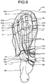
- FIG. 6 is a plan view of a plate 4A according to a first modification of the first embodiment.
- the plate 4A according to the first modification is different from the plate 4 according to the first embodiment in that the number of projections 40f is one and the number of recesses 40g is two.
- the first recess 40g from the front side is disposed at a position corresponding to the DIP joint Ja of the fifth toe. With the present modification, it is possible to achieve effects similar to those of the first embodiment described above.
- FIG. 7 is a plan view of a plate 4B according to a second modification of the first embodiment.
- the plate 4B according to the second modification is different from the plate 4 according to the first embodiment in that the number of projections 40f is one and the number of recesses 40g is two and that the depth of each recess 40g is increased to at least a position corresponding to the fifth toe.
- the first recess 40g from the front side is disposed at a position corresponding to the DIP joint Ja of the fifth toe
- the second recess 40g from the front side is disposed at a position corresponding to the MP joint Jc of the fifth toe.
- the present modification it is possible to further facilitate partial deformation of the plate 4B to allow the DIP joint Ja and the MP joint Jc of the fifth toe to easily move.
- the wearer easily moves the DIP joint Ja and the MP joint Jc of the fifth toe to take quick turns and fine steps.
- FIG. 8 is a plan view of a plate 4C according to a third modification of the first embodiment.
- the plate 4C according to the third modification is different from the plate 4 according to the first embodiment in that a projection 40f and a recess 40g are formed on the medial-foot-side end edge 40c.
- the medial-foot-side end edge 40c is formed alternately with a projection 40f projecting away from the shoe center axis C in the foot width direction of the sole 3 and a recess 40g recessed to be closer to the shoe center axis C in the foot width direction of the sole 3.
- the number of projections 40f is not particularly limited but is one in the present modification.
- the number of recesses 40g is not particularly limited but is two in the present modification.
- At least one of the recesses 40g is preferably disposed at a position corresponding to the MP joint Jc of the first toe.
- the second recess 40g from the front side is disposed at the position corresponding to the MP joint Jc of the first toe.
- the depth of each recess 40g is preferably less than 20% of the width along the foot width direction of the portion of the plate 4C corresponding to each recess 40g, or 8 mm to 10 mm from the medial-foot-side end edge 40c toward the lateral foot side. According to the present modification, it is possible to facilitate deformation of the medial foot side portion of the plate 4C to allow the MP joint Jc of the first toe to easily move. Thus, when a wearer goes down a slope on an uneven ground, the wearer easily moves the MP joint Jc of the first toe to take quick turns and fine steps.
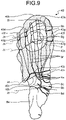
- FIG. 9 is a plan view of a plate 4D according to a fourth modification of the first embodiment.
- the plate 4D according to the fourth modification is different from the plate 4 according to the first embodiment in that a projection 40f and a recess 40g are formed on both the lateral-foot-side end edge 40d and the medial-foot-side end edge 40c.
- the number of projections 40f on the lateral-foot-side end edge 40d is three in the present modification.
- the number of recesses 40g on the lateral-foot-side end edge 40d is four in the present modification.
- the number of projections 40f on the medial-foot-side end edge 40c is one in the present modification.
- the number of recesses 40g on the medial-foot-side end edge 40c is two in the present modification. According to the present modification, it is possible to facilitate deformation of both the lateral foot side portion and the medial foot side portion of the plate 4D to allow the first toe and the fifth toe to easily move. Thus, when a wearer goes down a slope on an uneven ground, the wearer easily moves the first toe and the fifth toe to take quick turns and fine steps.
- the projections 40f and the recesses 40g may be formed on at least one of the medial-foot-side end edge 40c and the lateral-foot-side end edge 40d.
- FIG. 10 is a plan view of a plate 4E according to a fifth modification of the first embodiment.
- the plate 4E according to the fifth modification is different from the plate 4 according to the first embodiment in that the plate 4E extends from the forefoot support portion R1 to the rearfoot support portion R3.
- the present modification it is possible to increase the rigidity of the sole 3 from the forefoot support portion R1 to the rearfoot support portion R3 to stably support the entire foot.
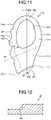
- FIG. 11 is a plan view of a plate 4F according to a sixth modification of the first embodiment.
- FIG. 12 is a cross-sectional view taken along line XII-XII in FIG. 11 .
- the plate 4F according to the sixth modification is different from the plate 4 according to the first embodiment in that the plate 4F is formed in a stepped shape in which the thickness decreases stepwise from the rear side toward the front side.
- FIG. 11 illustrates a boundary line S5 at a position where the thickness of the plate 4F changes. The thickness of the plate 4F changes in two steps.
- a stepped surface 40p illustrated in FIG. 12 is formed.
- the thickness of a region of the plate 4F positioned in front of the boundary line S5 is thinner than the thickness of the region positioned behind the boundary line S5.
- FIG. 13 is a plan view of a plate 4G according to a seventh modification of the first embodiment.
- FIG. 14 is a cross-sectional view taken along line XIV-XIV in FIG. 13 .
- the plate 4G according to the seventh modification is different from the plate 4 according to the first embodiment in that the plate 4G is formed in a stepped shape in which the thickness decreases stepwise from the rear side toward the front side.
- FIG. 13 illustrates boundary lines S6 and S7 at respective positions where the thickness of the plate 4G changes. The thickness of the plate 4G changes in three steps.
- a stepped surface 40q illustrated in FIG. 14 is formed.
- a stepped surface 40r illustrated in FIG. 14 is formed.
- the thickness of a region of the plate 4G positioned in front of the boundary line S6 is thinner than the thickness of a region positioned between the boundary line S6 and the boundary line S7.
- the thickness of a region of the plate 4G positioned between the boundary line S6 and the boundary line S7 is thinner than the thickness of a region positioned behind the boundary line S7.
- FIG. 15 is a plan view of a plate 4H according to an eighth modification of the first embodiment.
- the plate 4H according to the eighth modification is different from the plate 4 according to the first embodiment in that the thickness decreases from the opening 40a toward the outer edge of the plate 4H.
- FIG. 15 illustrates a boundary line S8 at a position where the thickness of the plate 4H changes.
- the thickness of the plate 4H changes in two steps.
- the plate 4H is formed in a stepped shape in which the thickness decreases stepwise from the opening 40a toward the outer edge of the plate 4H.
- a stepped surface is formed.
- the thickness of a region of the plate 4H positioned on the outer edge side of the plate 4H from the boundary line S8 is thinner than the thickness of a region positioned on the opening 40a side from the boundary line S8.
- the plate 4H may be formed in an inclined shape in which the thickness gradually decreases from the opening 40a toward the outer edge of the plate 4H.
- the thickness of a region of the plate 4H positioned on the opening 40a side from the boundary line S8 is uniform, and the thickness of a region of the plate 4H positioned on the outer edge side of the plate 4H from the boundary line S8 is inclined to gradually decrease from the boundary line S8 toward the outer edge of the plate 4H.
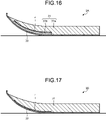
- FIG. 16 is a cross-sectional view of a sole 3A according to a ninth modification of the first embodiment.
- the opening 40a of the plate 4 is omitted, but the opening 40a is actually provided.
- the sole 3A according to the ninth modification is different from the sole 3 according to the first embodiment in that the midsole 31 has a two-layer structure and that the plate 4 is disposed in the midsole 31.
- the midsole 31 includes a first cushioning member 31a disposed on the outsole 30 and the plate 4, and a second cushioning member 31b disposed between the outsole 30 and the plate 4.
- the rigidity of the second cushioning member 31b is lower than the rigidity of the first cushioning member 31a.
- the plate 4 is disposed between the first cushioning member 31a and the second cushioning member 31b. According to the present modification, by disposing the plate 4 between the first cushioning member 31a and the second cushioning member 31b, it is possible to mitigate the impact at the time of landing. According to the present modification, since the rigidity of the second cushioning member 31b is lower than the rigidity of the first cushioning member 31a, the second cushioning member 31b is easily deformed at the time of kicking, and thus the ground contact area at the time of kicking is increased. Accordingly, it is possible to stably transmit the force of a foot to the ground.
- FIG. 17 is a cross-sectional view of a sole 3B according to a tenth modification of the first embodiment.
- the opening 40a of the plate 4 is omitted, but the opening 40a is actually provided.
- the sole 3B according to the tenth modification is different from the sole 3 according to the first embodiment in that the plate 4 is disposed in such a manner that the entire region of the plate 4 is in contact with the lower surface of the midsole 31 and the upper surface of the outsole 30.
- the present modification since the distance between the upper surface of the midsole 31 and the plate 4 is secured to be long, it is possible to mitigate the impact on the forefoot support portion R1 of the sole 3.
- FIG. 18 is a cross-sectional view of a sole 3C according to an eleventh modification of the first embodiment.
- the opening 40a of the plate 4 is omitted, but the opening 40a is actually provided.
- the sole 3C according to the eleventh modification is different from the sole 3 according to the first embodiment in that the plate 4 is disposed in such a manner that the entire region of the plate 4 is in contact with the upper surface of the midsole 31.
- the present modification since the distance between the sole of a wearer and the plate 4 is shortened, it is possible to enhance the transmission efficiency of the force from the plate 4 to the foot. Accordingly, it is possible to efficiently obtain the repulsive force, improve forward thrust, and reduce the loss of the force transmitted from the plate 4 to the foot.
- FIG. 19 is a cross-sectional view of a sole 3D according to a twelfth modification of the first embodiment.
- the opening 40a of the plate 4 is omitted, but the opening 40a is actually provided.
- the sole 3D according to the twelfth modification is different from the sole 3 according to the first embodiment in that the front end edge 40b of the plate 4 is disposed on the upper surface of the midsole 31 and the portion other than the front end edge 40b of the plate 4 is disposed in the midsole 31.
- the plate 4 is disposed in contact only with the midsole 31. That is, the plate 4 is disposed in a noncontact state with the outsole 30.
- the plate 4 warps toward the front side.
- the warp of the plate 4 is close to the warp of the outsole 30, and it is possible to expedite the transition from landing to leaving the ground.
- FIG. 20 is a cross-sectional view of a sole 3E according to a thirteenth modification of the first embodiment.
- the opening 40a of the plate 4 is omitted, but the opening 40a is actually provided.
- the sole 3E according to the thirteenth modification is different from the sole 3 according to the first embodiment in that the front end edge 40b of the plate 4 is disposed on the upper surface of the midsole 31, that the rear end edge 40e of the plate 4 is disposed in contact with the upper surface of the outsole 30, and that the portion other than the front end edge 40b and the rear end edge 40e of the plate 4 is disposed in the midsole 31.
- the radius of curvature of the plate 4 is smaller than the radius of curvature of the outsole 30 in the present modification.
- the warp of the plate 4 is further increased, and it is possible to further expedite the transition from landing to leaving the ground.
- FIG. 21 is a cross-sectional view of a sole 3F according to a fourteenth modification of the first embodiment.
- the opening 40a of the plate 4 is omitted, but the opening 40a is actually provided.
- the sole 3F according to the fourteenth modification is different from the sole 3 according to the first embodiment in that the thickness of the entire region of the plate 4 is uniform and that the thickness of the plate 4 is increased.
- the thickness of the plate 4 is, for example, 3 mm. According to the present modification, by making the thickness of the entire plate 4 uniform and thicker, it is possible to increase the rigidity of the entire plate 4.
- FIG. 22 is a cross-sectional view of a sole 3G according to a fifteenth modification of the first embodiment.
- the opening 40a of the plate 4 is omitted, but the opening 40a is actually provided.
- the sole 3G according to the fifteenth modification is different from the sole 3 according to the first embodiment in that the thickness of the entire region of the plate 4 is uniform and that the thickness of the plate 4 is reduced.
- the thickness of the plate 4 is, for example, 1.2 mm. According to the present modification, by making the thickness of the entire plate 4 uniform and thinner, it is possible to reduce the weight of the plate 4.
- FIG. 23 is a plan view of a sole 3H according to a second embodiment.
- the sole 3H according to the second embodiment is different from the sole 3 according to the first embodiment in that a plate 4I includes a first plate 41 and a second plate 42 having different rigidity.
- the first plate 41 is hatched to distinguish the first plate 41 from the second plate 42.
- the plate 4I includes the first plate 41 and the second plate 42.
- the first plate 41 is disposed on the lateral foot side portion of the plate 4I from the center in the foot width direction.
- the first plate 41 is disposed at a position corresponding to the third toe to the fifth toe in the thickness direction of the sole 3H.
- the second plate 42 is disposed on the medial foot side portion of the plate 4I from the center in the foot width direction.
- the second plate 42 is disposed at a position corresponding to the first toe to the second toe in the thickness direction of the sole 3H.
- the first plate 41 and the second plate 42 may be integrally formed, or the first plate 41 and the second plate 42 formed separately may be fixed with a bonding agent or the like.
- the rigidity of the first plate 41 is lower than the rigidity of the second plate 42.
- the first plate 41 is designed to have a structure with rigidity lower than the second plate 42 or is formed of a material having rigidity lower than the material of the second plate 42. Examples of the structure in which the rigidity of the first plate 41 is lower than that of the second plate 42 include designing the thickness of the first plate 41 to be thinner than the thickness of the second plate 42, punching the first plate 41, dimpling the second plate 42, and forming a rib on the second plate 42.
- the first plate 41 is disposed at a position corresponding to the third toe to the fifth toe in the thickness direction of the sole 3H, and the rigidity of the first plate 41 is lower than the rigidity of the second plate 42, which allow the third toe to the fifth toe to easily move.
- the wearer when a wearer goes down a slope on an uneven ground, the wearer easily moves the third toe to the fifth toe to take quick turns and fine steps. It is possible to reduce the weight of the plate 41.
- FIG. 24 is a plan view of a sole 3I according to a third embodiment.
- the sole 3I according to the third embodiment is different from the sole 3 according to the first embodiment in that a plate 4J includes a first plate 41 and a second plate 42 having different rigidity.
- the first plate 41 is hatched to distinguish the first plate 41 from the second plate 42.
- the plate 4J includes a plurality of first plates 41 and a second plate 42.
- the first plates 41 are separated from each other in the front-rear direction and the foot width direction.
- the first plates 41 are disposed to be dotted in the entire region of the plate 41.
- the first plates 41 are disposed at positions corresponding to the first toe to the fifth toe in the thickness direction of the sole 31.
- the shape of the first plates 41 each in plan view is a circular shape.
- the second plate 42 is disposed in a portion of the plate 4J other than the first plates 41.
- the first plate 41 and the second plate 42 may be integrally formed, or the first plate 41 and the second plate 42 formed separately may be fixed with a bonding agent or the like.
- the rigidity of the first plate 41 is lower than the rigidity of the second plate 42.
- the first plate 41 is designed to have a structure with rigidity lower than the second plate 42 or is formed of a material having rigidity lower than the material of the second plate 42. Examples of the structure in which the rigidity of the first plate 41 is lower than that of the second plate 42 include designing the thickness of the first plate 41 to be thinner than the thickness of the second plate 42, punching the first plate 41, dimpling the second plate 42, and forming a rib on the second plate 42.
- the first plates 41 are disposed at positions corresponding to the first toe to the fifth toe in the thickness direction of the sole 31, and the rigidity of the first plates 41 is lower than the rigidity of the second plate 42, which allow the first toe to the fifth toe to easily move.
- the wearer when a wearer goes down a slope on an uneven ground, the wearer easily moves the first toe and the fifth toe to take quick turns and fine steps. It is possible to reduce the weight of the plate 4J.
- FIG. 25 is a plan view of a sole 3J according to a fourth embodiment.
- the sole 3J according to the fourth embodiment is different from the sole 3 according to the first embodiment in that a plate 4K includes a first plate 41 and a second plate 42 having different rigidity.
- the first plate 41 is hatched to distinguish the first plate 41 from the second plate 42.
- the plate 4K includes the first plate 41 and the second plate 42.
- the first plate 41 is disposed at a position corresponding to the metatarsal Bf of the third toe in the thickness direction of the sole 3J.
- the rear edge of the first plate 41 is a part of the rear end edge 40e.
- the second plate 42 is disposed in a portion of the plate 4K other than the first plates 41.
- the first plate 41 and the second plate 42 may be integrally formed, or the first plate 41 and the second plate 42 formed separately may be fixed with a bonding agent or the like.
- the rigidity of the first plate 41 is lower than the rigidity of the second plate 42.
- the first plate 41 is designed to have a structure with rigidity lower than the second plate 42 or is formed of a material having rigidity lower than the material of the second plate 42. Examples of the structure in which the rigidity of the first plate 41 is lower than that of the second plate 42 include designing the thickness of the first plate 41 to be thinner than the thickness of the second plate 42, punching the first plate 41, dimpling the second plate 42, and forming a rib on the second plate 42.
- the first plate 41 is disposed at a position corresponding to the metatarsal Bf of the third toe in the thickness direction of the sole 3J, and the rigidity of the first plate 41 is lower than the rigidity of the second plate 42, which allow the third toe to easily move while the rigidity of the plate 4K is sufficiently secured.
- the wearer when a wearer goes down a slope on an uneven ground, the wearer easily moves the third toe to take quick turns and fine steps. It is possible to reduce the weight of the plate 4K.
- the sole according to the present invention has an effect of preventing movement of the toes of a foot from being hindered by a plate while securing functions by the plate of increasing thrust and of reducing transmission of upthrust to the foot.
Landscapes
- Chemical & Material Sciences (AREA)
- Engineering & Computer Science (AREA)
- Materials Engineering (AREA)
- Footwear And Its Accessory, Manufacturing Method And Apparatuses (AREA)
Abstract
Description
- The present application claims priority to and incorporates by reference the entire contents of
Japanese Patent Application No. 2021-082586 filed in Japan on May 14, 2021 - The present invention relates to a sole including a plate and a shoe.
- As a sole of a conventional shoe, a sole provided with a hard plate is known. The plate has a function of increasing the rigidity of the sole to prevent the shoe from bending and increase forward thrust. When a wearer runs on a paved road, the function of the plate can be maximized to enhance the running efficiency.
- Unfortunately, when a wearer runs on an uneven ground, the wearer is irregularly thrusted up when landing on the uneven ground. Thus, if a shoe has the plate, the upthrust is easily transmitted to the foot through the plate, and the load on the foot increases. For this reason, considering the case of running on an uneven ground, the plate is required to have a function of reducing transmission of upthrust to a foot in addition to the function of increasing thrust. As a plate having such a function,
JP 2018-534028 A - When a wearer goes down a slope on an uneven ground or the like, the wearer needs to move the toes to take quick turns and fine steps. Unfortunately, in the technique disclosed in
JP 2018-534028 A - The present invention has been made in view of the above, and an object of the present invention is to obtain a sole that prevents movement of the toes of a foot from being hindered by a plate while securing functions by the plate of increasing thrust and of reducing transmission of upthrust to the foot.
- In order to solve the above-described problem and achieve the object, a sole connecting a forefoot support portion supporting a forefoot of a foot, a midfoot support portion supporting a midfoot of the foot, and a rearfoot support portion supporting a rearfoot of the foot in this order from a front side, the sole includes: an outsole provided with a ground contact surface; a midsole disposed above the outsole; and a plate disposed above the outsole and on at least the forefoot support portion and the midfoot support portion, the plate having hardness higher than hardness of the midsole. The plate is provided with an opening at a position corresponding to a region at least from a proximal phalanx of a second toe to a proximal phalanx of a third toe, the plate has an outer edge including a medial-foot-side end edge positioned on a medial foot side from the opening and a lateral-foot-side end edge positioned on a lateral foot side from the opening, and at least one of the medial-foot-side end edge and the lateral-foot-side end edge is formed alternately with a projection projecting away from a shoe center axis in a foot width direction of the sole and a recess recessed to be closer to the shoe center axis in a foot width direction of the sole.
-
-
FIG. 1 is a plan view schematically illustrating a shoe according to a first embodiment of the present invention overlapped on a skeleton model of a foot; -
FIG. 2 is a side view of the shoe on a lateral foot side according to the first embodiment; -
FIG. 3 is a cross-sectional view taken along line III-III inFIG. 1 ; -
FIG. 4 is a plan view of a plate according to the first embodiment; -
FIG. 5 is a cross-sectional view taken along line V-V inFIG. 4 ; -
FIG. 6 is a plan view of a plate according to a first modification of the first embodiment; -
FIG. 7 is a plan view of a plate according to a second modification of the first embodiment; -
FIG. 8 is a plan view of a plate according to a third modification of the first embodiment; -
FIG. 9 is a plan view of a plate according to a fourth modification of the first embodiment; -
FIG. 10 is a plan view of a plate according to a fifth modification of the first embodiment; -
FIG. 11 is a plan view of a plate according to a sixth modification of the first embodiment; -
FIG. 12 is a cross-sectional view taken along line XII-XII inFIG. 11 ; -
FIG. 13 is a plan view of a plate according to a seventh modification of the first embodiment; -
FIG. 14 is a cross-sectional view taken along line XIV-XIV inFIG. 13 ; -
FIG. 15 is a plan view of a plate according to an eighth modification of the first embodiment; -
FIG. 16 is a cross-sectional view of a sole according to a ninth modification of the first embodiment; -
FIG. 17 is a cross-sectional view of a sole according to a tenth modification of the first embodiment; -
FIG. 18 is a cross-sectional view of a sole according to an eleventh modification of the first embodiment; -
FIG. 19 is a cross-sectional view of a sole according to a twelfth modification of the first embodiment; -
FIG. 20 is a cross-sectional view of a sole according to a thirteenth modification of the first embodiment; -
FIG. 21 is a cross-sectional view of a sole according to a fourteenth modification of the first embodiment; -
FIG. 22 is a cross-sectional view of a sole according to a fifteenth modification of the first embodiment; -
FIG. 23 is a plan view of a sole according to a second embodiment; -
FIG. 24 is a plan view of a sole according to a third embodiment; and -
FIG. 25 is a plan view of a sole according to a fourth embodiment. - Hereinafter, embodiments of a sole and a shoe according to the present invention will be described in detail with reference to the drawings. Note that the present invention is not limited by the embodiments. In the following description, the same portions are denoted by the same reference signs, and redundant description will be omitted.
-
FIG. 1 is a plan view schematically illustrating ashoe 1 according to a first embodiment of the present invention overlapped on a skeleton model of a foot. In the drawings includingFIG. 1 , only theshoe 1 for a left foot is illustrated. Since theshoe 1 has a left-right symmetrical structure for a left foot and a right foot, only theshoe 1 for a left foot is described in the present embodiment, and the description of theshoe 1 for a right foot is omitted. In the following embodiments, a direction in which a shoe center axis C, which is a perpendicular line passing through the center of a sole 3 in a plan view of theshoe 1, extends is referred to as a front-rear direction, and a direction orthogonal to the front-rear direction in a plan view of theshoe 1 is referred to as a foot width direction. - In addition, of the front-rear direction, a direction directed from the end on the side where the sole 3 supporting the rearfoot of a foot is positioned toward the end on the side where the sole 3 supporting the forefoot of the foot is positioned is referred to as a front side, and of the front-rear direction, a direction directed from the end on the side where the sole 3 supporting the forefoot of the foot is positioned toward the end on the side where the sole 3 supporting the rearfoot of the foot is positioned is referred to as a rear side.
- In addition, a median side of a foot in the anatomical position is referred to as a medial foot side, and the side opposite to the median side of the foot in the anatomical position is referred to as a lateral foot side. That is, the side closer to the median line in the anatomical position is referred to as the medial foot side, and the side farther from the median line in the anatomical position is referred to as the lateral foot side.
- In addition, a height direction means a direction orthogonal to both the front-rear direction and the foot width direction unless otherwise specified. In addition, a thickness means a dimension in the thickness direction of the sole 3 unless otherwise specified.
- The foot of a human body mainly includes a cuneiform Ba, a cuboid Bb, a navicular Bc, a talus Bd, a calcaneus Be, a metatarsal Bf, a proximal phalanx Bg, a middle phalanx Bh, and a distal phalanx Bi. The joints of a foot include a DIP joint Ja that is a distal interphalangeal joint, a PIP joint Jb that is a proximal interphalangeal joint, an MP joint Jc that is a metatarsopharangeal joint, a Lisfranc joint Jd, and a Chopart joint Je.
- A forefoot of a foot refers to a part positioned anterior to the MP joint Jc. A midfoot of the foot refers to a part from the MP joint Jc to the Chopart joint Je. A rearfoot of the foot refers to a part positioned posterior to the Chopart joint Je.
- The sole 3 includes a forefoot support portion R1 that supports the forefoot of a foot of a wearer with a standard body shape, a midfoot support portion R2 that supports the midfoot of a foot of a wearer with a standard body shape, and a rearfoot support portion R3 that supports the rearfoot portion of a foot of a wearer with a standard body shape. The forefoot support portion R1, the midfoot support portion R2, and the rearfoot support portion R3 are connected in this order from the front side of the sole 3 in the front-rear direction.
- A line along the foot width direction passing through a position corresponding to about 36% of the dimension of the sole 3 from the front end of the sole 3 in the front-rear direction is defined as a first boundary line S1, and a line along the foot width direction passing through a position corresponding to about 70% of the dimension of the sole 3 from the front end of the sole 3 in the front-rear direction is defined as a second boundary line S2. The first boundary line S1 is a line roughly along the MP joint Jc of a wearer with a standard body shape, and the second boundary line S2 is a line roughly along the Chopart joint Je of a wearer with a standard body shape. The forefoot support portion R1 is positioned in front of the first boundary line S1. The midfoot support portion R2 is positioned between the first boundary line S1 and the second boundary line S2. The rearfoot support portion R3 is positioned behind the second boundary line S2.
-
FIG. 2 is a side view of theshoe 1 on the lateral foot side according to the first embodiment. Theshoe 1 is preferably a running shoe for trail but may be a running shoe for road, other sports shoe, and walking shoe. Theshoe 1 includes an upper 2 and a sole 3. - The upper 2 is positioned above the sole 3. The upper 2 includes an
upper body 20 and ashoe tongue 21. - The
upper body 20 covers a part on the instep side of a foot. At the upper portion of theupper body 20, afoot insertion opening 20a for inserting a foot of a wearer and anopening 20b communicating with thefoot insertion opening 20a and extending from thefoot insertion opening 20a to the front side are formed. On both side edges of theopening 20b in the foot width direction, a plurality ofstring passing portions 20c spaced apart from each other in the front-rear direction is provided.FIG. 2 illustrates only thestring passing portions 20c provided on the side edge on the lateral foot side of theopening 20b. A shoelace (not illustrated) is alternately passed through thestring passing portions 20c provided on the side edge on the lateral foot side of theopening 20b and thestring passing portions 20c provided on the side edge on the medial foot side. - In the present embodiment, the upper 2 including the
shoe tongue 21 and the shoe lace is described as an example, but the upper 2 may have a monosock structure in which a portion corresponding to theshoe tongue 21 is integrated with an ankle portion of theupper body 20. A hook-and-loop fastener may be used instead of the shoelace to bring theupper body 20 into close contact with a foot. If a hook-and-loop fastener is used to bring theupper body 20 into close contact with a foot, thestring passing portions 20c are not formed in theupper body 20. - The
shoe tongue 21 is a member for protecting the instep of a wearer. Theshoe tongue 21 covers theopening 20b inside theupper body 20. Theshoe tongue 21 is fixed to theupper body 20 by stitching, welding, bonding, or a combination thereof. The material of theupper body 20 and theshoe tongue 21 is, for example, woven fabric, knitted fabric, synthetic leather, or resin. In particular, in theshoe 1 required to have air permeability and lightweight property, the material of theupper body 20 and theshoe tongue 21 is preferably a double raschel warp knitted fabric knitted with polyester yarn. Note that the material of theupper body 20 and theshoe tongue 21 is not limited to those exemplified. -
FIG. 3 is a cross-sectional view taken along line III-III inFIG. 1 . The sole 3 is positioned below the upper 2. The sole 3 covers the sole of a wearer. The shape of the toe portion of the sole 3 is a shape warping up toward the front side, that is, a so-called tow spring shape. The sole 3 includes anoutsole 30 provided with aground contact surface 30a, amidsole 31 disposed above theoutsole 30, and aplate 4. The sole 3 is fixed to the upper 2 by stitching, welding, bonding, or a combination thereof. The lower surface of theoutsole 30 serves as theground contact surface 30a to contact on the ground. Themidsole 31 is positioned on the upper surface of theoutsole 30 and has a cushioning property. The sole 3 includes an inner sole (not illustrated) that covers the lower opening of theupper body 20. The inner sole is fixed to the upper surface of themidsole 31 by bonding or welding. The inner sole is fixed to the lower edge of theupper body 20 by stitching. The sole 3 may have a structure in which the inner sole is omitted. Theshoe 1 may include an insole. If theshoe 1 includes an insole, the insole is placed on the sole 3 inside the upper 2. - The
plate 4 has hardness higher than hardness of themidsole 31. The material of theplate 4 is, for example, short carbon fiber reinforced material, fiber reinforced resin, non-fiber reinforced resin, or fiber fabric material. The flexural modulus of the short carbon fiber reinforced material used as the material of theplate 4 is desirably 5 Gpa to 15 Gpa. The fiber reinforced resin is, for example, carbon fiber, glass fiber, aramid fiber, Dyneema fiber, Zylon fiber, or boron fiber. If the material of theplate 4 is the fiber reinforced resin, the rigidity and the load support effect of theplate 4 can be enhanced. The non-fiber reinforced resin is, for example, polymer resin. The polymer resin is, for example, thermoplastic polyurethane (TPU) or thermoplastic elastomer (TPA). If the material of theplate 4 is the non-fiber reinforced resin, the rigidity of theplate 4 is reduced, which allows the toes to easily move. The fiber fabric material is, for example, knitted fabric or woven fabric of polyester fiber, nylon fiber, or the like. If the material of theplate 4 is the fiber fabric material, impact at the time of landing can be mitigated, and the weight of theplate 4 can be reduced. - The
plate 4 is disposed above theoutsole 30. In the present embodiment, theplate 4 is disposed between theoutsole 30 and themidsole 31. As illustrated inFIG. 1 , theplate 4 is disposed from the forefoot support portion R1 to the midfoot support portion R2 in the present embodiment. Theplate 4 is disposed from a position corresponding to the distal phalanx Bi to a position corresponding to the vicinity of the Lisfranc joint Jd in the front-rear direction. Theplate 4 is disposed from a position corresponding to the first toe to a position corresponding to the fifth toe in the foot width direction. InFIG. 1 , theplate 4 is disposed below themidsole 31 and cannot be seen, but theplate 4 is illustrated by a solid line and dot hatching for easy understanding. - The
plate 4 is provided with anopening 40a passing through in the thickness direction of the sole 3. The shape of theopening 40a in plan view may be a polygon, such as a triangle or a quadrangle, but is preferable to have a shape in which the corners illustrated inFIG. 1 are rounded in order to mitigate stress concentration at the corners. The shape of theopening 40a in plan view is not limited to the illustrated example and may be a shape having no corner, such as a circle or an ellipse. - The
opening 40a is provided at a position corresponding to a region from the distal phalanx Bi, the middle phalanx Bh, the proximal phalanx Bg, and the metatarsal Bf of the second toe to the middle phalanx Bh, the proximal phalanx Bg, and the metatarsal Bf of the fourth toe. Theopening 40a is not limited to the illustrated range and may be provided at a position corresponding to a region at least from the proximal phalanx Bg of the second toe to the proximal phalanx Bg of the third toe. Here, of the sole 3, a portion along the shoe center axis C is referred to as a shoe center. Theplate 4 is provided with theopening 40a in such a manner as to include a circle P whose center is positioned at 32% from the front end of the shoe center and whose diameter is 10% of the dimension of the shoe center. That is, theopening 40a is only required to be provided in such a manner as to include at least the circle P. - The outer edge of the
plate 4 includes afront end edge 40b positioned in front of theopening 40a, a medial-foot-side end edge 40c positioned on the medial foot side from theopening 40a, a lateral-foot-side end edge 40d positioned on the lateral foot side from theopening 40a, and arear end edge 40e positioned behind theopening 40a. Thefront end edge 40b extends in a curved shape to project to the front side. The medial-foot-side end edge 40c extends from the end portion on the medial foot side of thefront end edge 40b toward the rear side. The medial-foot-side end edge 40c extends in a curved shape to project to the medial foot side. - The lateral-foot-
side end edge 40d extends from the end portion on the lateral foot side of thefront end edge 40b toward the rear side. The lateral-foot-side end edge 40d is formed alternately with aprojection 40f projecting away from the shoe center axis C in the foot width direction of the sole 3 and arecess 40g recessed to be closer to the shoe center axis C in the foot width direction of the sole 3. The number ofprojections 40f is not particularly limited but is three in the present embodiment. The number ofrecesses 40g is not particularly limited but is four in the present embodiment. One of therecesses 40g is preferably disposed at a position corresponding to the DIP joint Ja of the fifth toe. In the present embodiment, thesecond recess 40g from the front side is disposed at the position corresponding to the DIP joint Ja of the fifth toe. The depth of eachrecess 40g is preferably less than 20% of the width along the foot width direction of the portion of theplate 4 corresponding to eachrecess 40g, or 8 mm to 10 mm from the lateral-foot-side end edge 40d toward the medial foot side. - The
rear end edge 40e connects the rear end portions of the medial-foot-side end edge 40c and the lateral-foot-side end edge 40d. Therear end edge 40e is formed with aninclined portion 40h inclined to be positioned forward from the lateral foot side toward the medial foot side, and aprotrusion 40i continuous with an end portion of theinclined portion 40h on the medial foot side and protruding toward the rear side. At the boundary between theinclined portion 40h and theprotrusion 40i, aconstricted portion 40j recessed toward the front side is formed. Therear end edge 40e extends from a position corresponding to the metatarsal Bf of the fifth toe to a position corresponding to the metatarsal Bf of the first toe. Theinclined portion 40h is formed from the end portion of therear end edge 40e on the lateral foot side to the medial foot side from the center in the foot width direction. Theinclined portion 40h is disposed from a position corresponding to the metatarsal Bf of the fifth toe to a position corresponding to the metatarsal Bf of the second toe. Theprotrusion 40i is formed at the end portion of therear end edge 40e on the medial foot side. Theprotrusion 40i is disposed from a position corresponding to the metatarsal Bf of the second toe to a position corresponding to the metatarsal Bf of the first toe. -
FIG. 4 is a plan view of theplate 4 according to the first embodiment.FIG. 5 is a cross-sectional view taken along line V-V inFIG. 4 . A line along the foot width direction passing through a front-most portion of theopening 40a illustrated inFIG. 4 is defined as a front boundary line S3, and a line along the foot width direction passing through a rear-most portion of theopening 40a is defined as a rear boundary line S4. Theplate 4 includes atiptoe region 40k positioned in front of theopening 40a, a medialfoot side region 40m positioned on the medial foot side from theopening 40a, a lateralfoot side region 40n positioned on the lateral foot side from theopening 40a, and a rear region 40o positioned behind theopening 40a. Thetiptoe region 40k is positioned in front of the front boundary line S3. The medialfoot side region 40m is a region positioned on the medial foot side from theopening 40a and between the front boundary line S3 and the rear boundary line S4. The lateralfoot side region 40n is a region positioned on the lateral foot side from theopening 40a and between the front boundary line S3 and the rear boundary line S4. The rear region 40o is positioned behind the rear boundary line S4. - As illustrated in
FIG. 5 , the thickness of theplate 4 in the thickness direction of the sole 3 decreases from the rear side toward the front side. Specifically, theplate 4 is formed in an inclined shape that gradually becomes thinner from the rear side toward the front side. The thickness at and near therear end edge 40e is the thickest in theplate 4. The thickness at and near thefront end edge 40b is the thinnest in theplate 4. The thickness of the lateralfoot side region 40n is thinner than the thickness at and near therear end edge 40e and thicker than the thickness at and near thefront end edge 40b. Here, the thickness of thetiptoe region 40k, the thickness of the rear region 40o, and the thickness of the lateralfoot side region 40n in the thickness direction of the sole 3 are set to satisfy a relationship of b>c>a, where a is the thickness of thetiptoe region 40k, b is the thickness of the rear region 40o, and c is the thickness of the lateralfoot side region 40n. The thickness a of thetiptoe region 40k, the thickness b of the rear region 40o, and the thickness c of the lateralfoot side region 40n each mean an average thickness obtained by measuring the thickness at three points arbitrarily selected in therespective regions foot side region 40n is set to, for example, an intermediate thickness between the thickness a of thetiptoe region 40k and the thickness b of the rear region 40o. - Next, effects of the sole 3 according to the present embodiment will be described.
- In the present embodiment, as illustrated in
FIGS. 1 and3 , the sole 3 includes theplate 4 disposed above theoutsole 30 and on at least the forefoot support portion R1 and the midfoot support portion R2, and theplate 4 has hardness higher than hardness of themidsole 31. Accordingly, it is possible to increase the rigidity of the sole 3 to prevent theshoe 1 from bending and increase forward thrust. - In the present embodiment, the
plate 4 is provided with theopening 40a as illustrated inFIG. 1 . Accordingly, it is possible to reduce transmission of upthrust to the foot at the time of landing on an uneven ground and to reduce the load on the foot. In particular, by providing theopening 40a at a position corresponding to a region from the proximal phalanx Bg of the second toe and the proximal phalanx Bg of the third toe, where the upthrust is most likely to be felt, it is possible for a wearer to less feel the upthrust. By providing theopening 40a in theplate 4, it is possible to reduce the weight of theplate 4. Note that, by limiting the range of theopening 40a, it is possible to reduce decrease in the rigidity of the sole 3 due to the provision of theopening 40a and to secure forward thrust. - In the present embodiment, as illustrated in
FIG. 1 , the outer edge of theplate 4 includes the medial-foot-side end edge 40c positioned on the medial foot side from theopening 40a and the lateral-foot-side end edge 40d positioned on the lateral foot side from theopening 40a. The lateral-foot-side end edge 40d is formed alternately with theprojection 40f projecting away from the shoe center axis C in the foot width direction of the sole 3 and therecess 40g recessed to be closer to the shoe center axis C in the foot width direction of the sole 3. With this structure, it is possible to partially reduce the rigidity of theplate 4 to facilitate partial deformation of theplate 4. By providing therecesses 40g at a position corresponding to the toes, it is possible to prevent movement of the toes from being hindered by theplate 4. Thus, when a wearer goes down a slope on an uneven ground, the wearer easily moves the toes to take quick turns and fine steps. Note that, by setting the depth of eachrecess 40g to less than 20% of the width along the foot width direction of the portion of theplate 4 corresponding to eachrecess 40g, or to 8 mm to 10 mm from the lateral-foot-side end edge 40d toward the medial foot side, it is possible to reduce decrease in the rigidity of the sole 3 due to the provision of therecesses 40g and to secure forward thrust. - In the present embodiment, as illustrated in
FIG. 1 , arecess 40g is disposed at a position corresponding to at least the DIP joint Ja of the fifth toe, which allows the DIP joint Ja of the fifth toe to easily move. Thus, when a wearer goes down a slope on an uneven ground, the wearer easily moves the DIP joint Ja of the fifth toe to take quick turns and fine steps. - In the present embodiment, as illustrated in
FIG. 1 , theopening 40a has a rounded shape in plan view, and stress concentration at the edges of theopening 40a is prevented, which reduces the risk of damaging theplate 4. - In the present embodiment, as illustrated in
FIG. 1 , the outer edge of theplate 4 includes therear end edge 40e positioned behind theopening 40a, and therear end edge 40e is formed with theinclined portion 40h inclined to be positioned forward from the lateral foot side toward the medial foot side. This makes it easy to incline a foot around the horizontal axis along the front-rear direction. By forming, on therear end edge 40e, theprotrusion 40i continuous with the end portion of theinclined portion 40h on the medial foot side and protruding toward the rear side, it is possible to reduce decrease in the rigidity of the sole 3 due to the provision of theinclined portion 40h. Note that theprotrusion 40i may be omitted, and theinclined portion 40h may be formed over the entire length of therear end edge 40e. - In the present embodiment, as illustrated in
FIGS. 4 and 5 , the thickness of theplate 4 in the thickness direction of the sole 3 decreases from the rear side toward the front side via the lateral foot side, and thereby the rigidity of theplate 4 at a position corresponding to the third toe to the vicinity of the fifth toe is partially reduced, which allows the third toe to the fifth toe to more easily move. It is possible to reduce the weight of theplate 4. -
FIG. 6 is a plan view of a plate 4A according to a first modification of the first embodiment. The plate 4A according to the first modification is different from theplate 4 according to the first embodiment in that the number ofprojections 40f is one and the number ofrecesses 40g is two. In the present modification, thefirst recess 40g from the front side is disposed at a position corresponding to the DIP joint Ja of the fifth toe. With the present modification, it is possible to achieve effects similar to those of the first embodiment described above. -
FIG. 7 is a plan view of aplate 4B according to a second modification of the first embodiment. Theplate 4B according to the second modification is different from theplate 4 according to the first embodiment in that the number ofprojections 40f is one and the number ofrecesses 40g is two and that the depth of eachrecess 40g is increased to at least a position corresponding to the fifth toe. In the present modification, thefirst recess 40g from the front side is disposed at a position corresponding to the DIP joint Ja of the fifth toe, and thesecond recess 40g from the front side is disposed at a position corresponding to the MP joint Jc of the fifth toe. According to the present modification, it is possible to further facilitate partial deformation of theplate 4B to allow the DIP joint Ja and the MP joint Jc of the fifth toe to easily move. Thus, when a wearer goes down a slope on an uneven ground, the wearer easily moves the DIP joint Ja and the MP joint Jc of the fifth toe to take quick turns and fine steps. -
FIG. 8 is a plan view of aplate 4C according to a third modification of the first embodiment. Theplate 4C according to the third modification is different from theplate 4 according to the first embodiment in that aprojection 40f and arecess 40g are formed on the medial-foot-side end edge 40c. The medial-foot-side end edge 40c is formed alternately with aprojection 40f projecting away from the shoe center axis C in the foot width direction of the sole 3 and arecess 40g recessed to be closer to the shoe center axis C in the foot width direction of the sole 3. The number ofprojections 40f is not particularly limited but is one in the present modification. The number ofrecesses 40g is not particularly limited but is two in the present modification. At least one of therecesses 40g is preferably disposed at a position corresponding to the MP joint Jc of the first toe. In the present modification, thesecond recess 40g from the front side is disposed at the position corresponding to the MP joint Jc of the first toe. The depth of eachrecess 40g is preferably less than 20% of the width along the foot width direction of the portion of theplate 4C corresponding to eachrecess 40g, or 8 mm to 10 mm from the medial-foot-side end edge 40c toward the lateral foot side. According to the present modification, it is possible to facilitate deformation of the medial foot side portion of theplate 4C to allow the MP joint Jc of the first toe to easily move. Thus, when a wearer goes down a slope on an uneven ground, the wearer easily moves the MP joint Jc of the first toe to take quick turns and fine steps. -
FIG. 9 is a plan view of aplate 4D according to a fourth modification of the first embodiment. Theplate 4D according to the fourth modification is different from theplate 4 according to the first embodiment in that aprojection 40f and arecess 40g are formed on both the lateral-foot-side end edge 40d and the medial-foot-side end edge 40c. The number ofprojections 40f on the lateral-foot-side end edge 40d is three in the present modification. The number ofrecesses 40g on the lateral-foot-side end edge 40d is four in the present modification. The number ofprojections 40f on the medial-foot-side end edge 40c is one in the present modification. The number ofrecesses 40g on the medial-foot-side end edge 40c is two in the present modification. According to the present modification, it is possible to facilitate deformation of both the lateral foot side portion and the medial foot side portion of theplate 4D to allow the first toe and the fifth toe to easily move. Thus, when a wearer goes down a slope on an uneven ground, the wearer easily moves the first toe and the fifth toe to take quick turns and fine steps. Theprojections 40f and therecesses 40g may be formed on at least one of the medial-foot-side end edge 40c and the lateral-foot-side end edge 40d. -
FIG. 10 is a plan view of aplate 4E according to a fifth modification of the first embodiment. Theplate 4E according to the fifth modification is different from theplate 4 according to the first embodiment in that theplate 4E extends from the forefoot support portion R1 to the rearfoot support portion R3. According to the present modification, it is possible to increase the rigidity of the sole 3 from the forefoot support portion R1 to the rearfoot support portion R3 to stably support the entire foot. -
FIG. 11 is a plan view of aplate 4F according to a sixth modification of the first embodiment.FIG. 12 is a cross-sectional view taken along line XII-XII inFIG. 11 . Theplate 4F according to the sixth modification is different from theplate 4 according to the first embodiment in that theplate 4F is formed in a stepped shape in which the thickness decreases stepwise from the rear side toward the front side.FIG. 11 illustrates a boundary line S5 at a position where the thickness of theplate 4F changes. The thickness of theplate 4F changes in two steps. At a position corresponding to the boundary line S5 inFIG. 11 , a steppedsurface 40p illustrated inFIG. 12 is formed. As illustrated inFIGS. 11 and 12 , the thickness of a region of theplate 4F positioned in front of the boundary line S5 is thinner than the thickness of the region positioned behind the boundary line S5. With the present modification, it is possible to achieve effects similar to those of the first embodiment described above. -
FIG. 13 is a plan view of aplate 4G according to a seventh modification of the first embodiment.FIG. 14 is a cross-sectional view taken along line XIV-XIV inFIG. 13 . Theplate 4G according to the seventh modification is different from theplate 4 according to the first embodiment in that theplate 4G is formed in a stepped shape in which the thickness decreases stepwise from the rear side toward the front side.FIG. 13 illustrates boundary lines S6 and S7 at respective positions where the thickness of theplate 4G changes. The thickness of theplate 4G changes in three steps. At a position corresponding to the boundary line S6 inFIG. 13 , a steppedsurface 40q illustrated inFIG. 14 is formed. At a position corresponding to the boundary line S7 inFIG. 13 , a steppedsurface 40r illustrated inFIG. 14 is formed. As illustrated inFIGS. 13 and 14 , the thickness of a region of theplate 4G positioned in front of the boundary line S6 is thinner than the thickness of a region positioned between the boundary line S6 and the boundary line S7. The thickness of a region of theplate 4G positioned between the boundary line S6 and the boundary line S7 is thinner than the thickness of a region positioned behind the boundary line S7. With the present modification, it is possible to achieve effects similar to those of the first embodiment described above. -
FIG. 15 is a plan view of aplate 4H according to an eighth modification of the first embodiment. Theplate 4H according to the eighth modification is different from theplate 4 according to the first embodiment in that the thickness decreases from theopening 40a toward the outer edge of theplate 4H.FIG. 15 illustrates a boundary line S8 at a position where the thickness of theplate 4H changes. The thickness of theplate 4H changes in two steps. Theplate 4H is formed in a stepped shape in which the thickness decreases stepwise from theopening 40a toward the outer edge of theplate 4H. At a position corresponding to the boundary line S8 inFIG. 15 , a stepped surface is formed. The thickness of a region of theplate 4H positioned on the outer edge side of theplate 4H from the boundary line S8 is thinner than the thickness of a region positioned on theopening 40a side from the boundary line S8. - The
plate 4H may be formed in an inclined shape in which the thickness gradually decreases from theopening 40a toward the outer edge of theplate 4H. In this case, the thickness of a region of theplate 4H positioned on theopening 40a side from the boundary line S8 is uniform, and the thickness of a region of theplate 4H positioned on the outer edge side of theplate 4H from the boundary line S8 is inclined to gradually decrease from the boundary line S8 toward the outer edge of theplate 4H. With the present modification, it is possible to achieve effects similar to those of the first embodiment described above. -
FIG. 16 is a cross-sectional view of a sole 3A according to a ninth modification of the first embodiment. InFIG. 16 , theopening 40a of theplate 4 is omitted, but theopening 40a is actually provided. The sole 3A according to the ninth modification is different from the sole 3 according to the first embodiment in that themidsole 31 has a two-layer structure and that theplate 4 is disposed in themidsole 31. Themidsole 31 includes afirst cushioning member 31a disposed on theoutsole 30 and theplate 4, and asecond cushioning member 31b disposed between theoutsole 30 and theplate 4. The rigidity of thesecond cushioning member 31b is lower than the rigidity of thefirst cushioning member 31a. Theplate 4 is disposed between thefirst cushioning member 31a and thesecond cushioning member 31b. According to the present modification, by disposing theplate 4 between thefirst cushioning member 31a and thesecond cushioning member 31b, it is possible to mitigate the impact at the time of landing. According to the present modification, since the rigidity of thesecond cushioning member 31b is lower than the rigidity of thefirst cushioning member 31a, thesecond cushioning member 31b is easily deformed at the time of kicking, and thus the ground contact area at the time of kicking is increased. Accordingly, it is possible to stably transmit the force of a foot to the ground. -
FIG. 17 is a cross-sectional view of a sole 3B according to a tenth modification of the first embodiment. InFIG. 17 , theopening 40a of theplate 4 is omitted, but theopening 40a is actually provided. The sole 3B according to the tenth modification is different from the sole 3 according to the first embodiment in that theplate 4 is disposed in such a manner that the entire region of theplate 4 is in contact with the lower surface of themidsole 31 and the upper surface of theoutsole 30. According to the present modification, since the distance between the upper surface of themidsole 31 and theplate 4 is secured to be long, it is possible to mitigate the impact on the forefoot support portion R1 of the sole 3. -
FIG. 18 is a cross-sectional view of a sole 3C according to an eleventh modification of the first embodiment. InFIG. 18 , theopening 40a of theplate 4 is omitted, but theopening 40a is actually provided. The sole 3C according to the eleventh modification is different from the sole 3 according to the first embodiment in that theplate 4 is disposed in such a manner that the entire region of theplate 4 is in contact with the upper surface of themidsole 31. According to the present modification, since the distance between the sole of a wearer and theplate 4 is shortened, it is possible to enhance the transmission efficiency of the force from theplate 4 to the foot. Accordingly, it is possible to efficiently obtain the repulsive force, improve forward thrust, and reduce the loss of the force transmitted from theplate 4 to the foot. -
FIG. 19 is a cross-sectional view of a sole 3D according to a twelfth modification of the first embodiment. InFIG. 19 , theopening 40a of theplate 4 is omitted, but theopening 40a is actually provided. The sole 3D according to the twelfth modification is different from the sole 3 according to the first embodiment in that thefront end edge 40b of theplate 4 is disposed on the upper surface of themidsole 31 and the portion other than thefront end edge 40b of theplate 4 is disposed in themidsole 31. Theplate 4 is disposed in contact only with themidsole 31. That is, theplate 4 is disposed in a noncontact state with theoutsole 30. Theplate 4 warps toward the front side. According to the present modification, since thefront end edge 40b of theplate 4 is disposed on the upper surface of themidsole 31, the warp of theplate 4 is close to the warp of theoutsole 30, and it is possible to expedite the transition from landing to leaving the ground. -
FIG. 20 is a cross-sectional view of a sole 3E according to a thirteenth modification of the first embodiment. InFIG. 20 , theopening 40a of theplate 4 is omitted, but theopening 40a is actually provided. The sole 3E according to the thirteenth modification is different from the sole 3 according to the first embodiment in that thefront end edge 40b of theplate 4 is disposed on the upper surface of themidsole 31, that therear end edge 40e of theplate 4 is disposed in contact with the upper surface of theoutsole 30, and that the portion other than thefront end edge 40b and therear end edge 40e of theplate 4 is disposed in themidsole 31. The radius of curvature of theplate 4 is smaller than the radius of curvature of theoutsole 30 in the present modification. According to the present modification, since thefront end edge 40b of theplate 4 is disposed on the upper surface of themidsole 31 and therear end edge 40e of theplate 4 is disposed in contact with the upper surface of theoutsole 30, the warp of theplate 4 is further increased, and it is possible to further expedite the transition from landing to leaving the ground. -
FIG. 21 is a cross-sectional view of a sole 3F according to a fourteenth modification of the first embodiment. InFIG. 21 , theopening 40a of theplate 4 is omitted, but theopening 40a is actually provided. The sole 3F according to the fourteenth modification is different from the sole 3 according to the first embodiment in that the thickness of the entire region of theplate 4 is uniform and that the thickness of theplate 4 is increased. The thickness of theplate 4 is, for example, 3 mm. According to the present modification, by making the thickness of theentire plate 4 uniform and thicker, it is possible to increase the rigidity of theentire plate 4. -
FIG. 22 is a cross-sectional view of a sole 3G according to a fifteenth modification of the first embodiment. InFIG. 22 , theopening 40a of theplate 4 is omitted, but theopening 40a is actually provided. The sole 3G according to the fifteenth modification is different from the sole 3 according to the first embodiment in that the thickness of the entire region of theplate 4 is uniform and that the thickness of theplate 4 is reduced. The thickness of theplate 4 is, for example, 1.2 mm. According to the present modification, by making the thickness of theentire plate 4 uniform and thinner, it is possible to reduce the weight of theplate 4. -
FIG. 23 is a plan view of a sole 3H according to a second embodiment. The sole 3H according to the second embodiment is different from the sole 3 according to the first embodiment in that a plate 4I includes afirst plate 41 and asecond plate 42 having different rigidity. InFIG. 23 , thefirst plate 41 is hatched to distinguish thefirst plate 41 from thesecond plate 42. - The plate 4I includes the
first plate 41 and thesecond plate 42. Thefirst plate 41 is disposed on the lateral foot side portion of the plate 4I from the center in the foot width direction. Thefirst plate 41 is disposed at a position corresponding to the third toe to the fifth toe in the thickness direction of the sole 3H. Thesecond plate 42 is disposed on the medial foot side portion of the plate 4I from the center in the foot width direction. Thesecond plate 42 is disposed at a position corresponding to the first toe to the second toe in the thickness direction of the sole 3H. Thefirst plate 41 and thesecond plate 42 may be integrally formed, or thefirst plate 41 and thesecond plate 42 formed separately may be fixed with a bonding agent or the like. - The rigidity of the
first plate 41 is lower than the rigidity of thesecond plate 42. Thefirst plate 41 is designed to have a structure with rigidity lower than thesecond plate 42 or is formed of a material having rigidity lower than the material of thesecond plate 42. Examples of the structure in which the rigidity of thefirst plate 41 is lower than that of thesecond plate 42 include designing the thickness of thefirst plate 41 to be thinner than the thickness of thesecond plate 42, punching thefirst plate 41, dimpling thesecond plate 42, and forming a rib on thesecond plate 42. According to the present embodiment, thefirst plate 41 is disposed at a position corresponding to the third toe to the fifth toe in the thickness direction of the sole 3H, and the rigidity of thefirst plate 41 is lower than the rigidity of thesecond plate 42, which allow the third toe to the fifth toe to easily move. Thus, when a wearer goes down a slope on an uneven ground, the wearer easily moves the third toe to the fifth toe to take quick turns and fine steps. It is possible to reduce the weight of theplate 41. -
FIG. 24 is a plan view of a sole 3I according to a third embodiment. The sole 3I according to the third embodiment is different from the sole 3 according to the first embodiment in that a plate 4J includes afirst plate 41 and asecond plate 42 having different rigidity. InFIG. 24 , thefirst plate 41 is hatched to distinguish thefirst plate 41 from thesecond plate 42. - The plate 4J includes a plurality of
first plates 41 and asecond plate 42. Thefirst plates 41 are separated from each other in the front-rear direction and the foot width direction. Thefirst plates 41 are disposed to be dotted in the entire region of theplate 41. Thefirst plates 41 are disposed at positions corresponding to the first toe to the fifth toe in the thickness direction of the sole 31. The shape of thefirst plates 41 each in plan view is a circular shape. Thesecond plate 42 is disposed in a portion of the plate 4J other than thefirst plates 41. Thefirst plate 41 and thesecond plate 42 may be integrally formed, or thefirst plate 41 and thesecond plate 42 formed separately may be fixed with a bonding agent or the like. - The rigidity of the
first plate 41 is lower than the rigidity of thesecond plate 42. Thefirst plate 41 is designed to have a structure with rigidity lower than thesecond plate 42 or is formed of a material having rigidity lower than the material of thesecond plate 42. Examples of the structure in which the rigidity of thefirst plate 41 is lower than that of thesecond plate 42 include designing the thickness of thefirst plate 41 to be thinner than the thickness of thesecond plate 42, punching thefirst plate 41, dimpling thesecond plate 42, and forming a rib on thesecond plate 42. According to the present embodiment, thefirst plates 41 are disposed at positions corresponding to the first toe to the fifth toe in the thickness direction of the sole 31, and the rigidity of thefirst plates 41 is lower than the rigidity of thesecond plate 42, which allow the first toe to the fifth toe to easily move. Thus, when a wearer goes down a slope on an uneven ground, the wearer easily moves the first toe and the fifth toe to take quick turns and fine steps. It is possible to reduce the weight of the plate 4J. -
FIG. 25 is a plan view of a sole 3J according to a fourth embodiment. The sole 3J according to the fourth embodiment is different from the sole 3 according to the first embodiment in that aplate 4K includes afirst plate 41 and asecond plate 42 having different rigidity. InFIG. 25 , thefirst plate 41 is hatched to distinguish thefirst plate 41 from thesecond plate 42. - The
plate 4K includes thefirst plate 41 and thesecond plate 42. Thefirst plate 41 is disposed at a position corresponding to the metatarsal Bf of the third toe in the thickness direction of the sole 3J. The rear edge of thefirst plate 41 is a part of therear end edge 40e. Thesecond plate 42 is disposed in a portion of theplate 4K other than thefirst plates 41. Thefirst plate 41 and thesecond plate 42 may be integrally formed, or thefirst plate 41 and thesecond plate 42 formed separately may be fixed with a bonding agent or the like. - The rigidity of the
first plate 41 is lower than the rigidity of thesecond plate 42. Thefirst plate 41 is designed to have a structure with rigidity lower than thesecond plate 42 or is formed of a material having rigidity lower than the material of thesecond plate 42. Examples of the structure in which the rigidity of thefirst plate 41 is lower than that of thesecond plate 42 include designing the thickness of thefirst plate 41 to be thinner than the thickness of thesecond plate 42, punching thefirst plate 41, dimpling thesecond plate 42, and forming a rib on thesecond plate 42. According to the present embodiment, thefirst plate 41 is disposed at a position corresponding to the metatarsal Bf of the third toe in the thickness direction of the sole 3J, and the rigidity of thefirst plate 41 is lower than the rigidity of thesecond plate 42, which allow the third toe to easily move while the rigidity of theplate 4K is sufficiently secured. Thus, when a wearer goes down a slope on an uneven ground, the wearer easily moves the third toe to take quick turns and fine steps. It is possible to reduce the weight of theplate 4K. - The sole according to the present invention has an effect of preventing movement of the toes of a foot from being hindered by a plate while securing functions by the plate of increasing thrust and of reducing transmission of upthrust to the foot.
- The configurations described in the above embodiments merely show examples of the present invention and can be combined with another known technique, and a part of each configuration can be omitted or changed without departing from the gist of the present invention.
Claims (10)
- A sole (3,3A,3B,3C,3D,3E,3F,3G,3H,3I,3J) connecting a forefoot support portion (R1) supporting a forefoot of a foot, a midfoot support portion (R2) supporting a midfoot of the foot, and a rearfoot support portion (R3) supporting a rearfoot of the foot in this order from a front side, the sole (3,3A,3B,3C,3D,3E,3F,3G,3H,3I,3J) comprising:an outsole (30) provided with a ground contact surface (30a);a midsole (31) disposed above the outsole (30); anda plate (4,4A,4B,4C,4D,4E,4F,4G,4H,4I,4J,4K) disposed above the outsole (30) and on at least the forefoot support portion (R1) and the midfoot support portion (R2), the plate (4,4A,4B,4C,4D,4E,4F,4G,4H,4I,4J,4K) having hardness higher than hardness of the midsole (31), whereinthe plate (4,4A,4B,4C,4D,4E,4F,4G,4H,4I,4J,4K) is provided with an opening (40a) at a position corresponding to a region at least from a proximal phalanx (Bg) of a second toe to a proximal phalanx (Bg) of a third toe,the plate (4,4A,4B,4C,4D,4E,4F,4G,4H,4I,4J,4K) has an outer edge including a medial-foot-side end edge (40c) positioned on a medial foot side from the opening (40a) and a lateral-foot-side end edge (40d) positioned on a lateral foot side from the opening (40a), andat least one of the medial-foot-side end edge (40c) and the lateral-foot-side end edge (40d) is formed alternately with a projection (40f) projecting away from a shoe center axis (C) in a foot width direction of the sole (3,3A,3B,3C,3D,3E,3F,3G,3H,3I,3J) and a recess (40g) recessed to be closer to the shoe center axis (C) in a foot width direction of the sole (3,3A,3B,3C,3D,3E,3F,3G,3H,3I,3J).
- The sole (3,3A,3B,3C,3D,3E,3F,3G,3H,3I,3J) according to claim 1, wherein the recess (40g) is disposed at a position corresponding to at least a distal interphalangeal joint (Ja) of a fifth toe.
- The sole (3,3A,3B,3C,3D,3E,3F,3G,3H,3I,3J) according to claim 1 or 2, wherein the opening (40a) has a rounded shape in plan view.
- The sole (3,3A,3B,3C,3D,3E,3F,3G,3H,3I,3J) according to any one of claims 1 to 3, whereinthe outer edge of the plate (4,4A,4B,4C,4D,4E,4F,4G,4H,4I,4J,4K) includes a rear end edge (40e) positioned behind the opening (40a), andthe rear end edge (40e) is formed with an inclined portion (40h) inclined to be positioned forward from the lateral foot side toward the medial foot side, and a protrusion (40i) continuous with an end portion of the inclined portion (40h) on the medial foot side and protruding toward a rear side.
- A sole (3,3A,3B,3C,3D,3E,3F,3G,3H,3I,3J) connecting a forefoot support portion (R1) supporting a forefoot of a foot, a midfoot support portion (R2) supporting a midfoot of the foot, and a rearfoot support portion (R3) supporting a rearfoot of the foot in this order from a front side, the sole (3,3A,3B,3C,3D,3E,3F,3G,3H,3I,3J) comprising:an outsole (30) provided with a ground contact surface (30a);a midsole (31) disposed above the outsole (30); anda plate (4,4A,4B,4C,4D,4E,4F,4G,4H,4I,4J,4K) disposed above the outsole (30) and on at least the forefoot support portion (R1) and the midfoot support portion (R2), the plate (4, 4A, 4B, 4C, 4D, 4E, 4F, 4G, 4H, 4I, 4J, 4K) having rigidity higher than rigidity of the midsole (31), whereinthe plate (4,4A,4B,4C,4D,4E,4F,4G,4H,4I,4J,4K) is provided with an opening (40a) at a position corresponding to a region at least from a proximal phalanx (Bg) of a second toe to a proximal phalanx (Bg) of a third toe, andthe plate (4, 4A, 4B, 4C, 4D, 4E, 4F, 4G, 4H, 4I, 4J, 4K) has a thickness in a thickness direction of the sole (3, 3A, 3B, 3C, 3D, 3E, 3F, 3G, 3H, 3I, 3J) decreasing from a rear side toward the front side or decreasing from the opening (40a) toward an outer edge of the plate (4,4A,4B,4C,4D,4E,4F,4G,4H,4I,4J,4K) .
- The sole (3,3A,3B,3C,3D,3E,3F,3G,3H,3I,3J) according to claims 5, whereinthe plate (4,4A,4B,4C,4D,4E,4F,4G,4H,4I,4J,4K) includes a tiptoe region (40k) positioned in front of the opening (40a), a lateral foot side region (40n) positioned on a lateral foot side from the opening (40a), and a rear region (40o) positioned behind the opening (40a), anda thickness of the tiptoe region (40k), a thickness of the rear region (40o), and a thickness of the lateral foot side region (40n) in the thickness direction are set to satisfy a relationship of b>c>a, where a is the thickness of the tiptoe region (40k), b is the thickness of the rear region (40o), and c is the thickness of the lateral foot side region (40n).
- A sole (3,3A,3B,3C,3D,3E,3F,3G,3H,3I,3J) connecting a forefoot support portion (R1) supporting a forefoot of a foot, a midfoot support portion (R2) supporting a midfoot of the foot, and a rearfoot support portion (R3) supporting a rearfoot of the foot in this order from a front side, the sole (3,3A,3B,3C,3D,3E,3F,3G,3H,3I,3J) comprising:an outsole (30) provided with a ground contact surface (30a);a midsole (31) disposed above the outsole (30); anda plate (4,4A,4B,4C,4D,4E,4F,4G,4H,4I,4J,4K) disposed above the outsole (30) and on at least the forefoot support portion (R1) and the midfoot support portion (R2), the plate (4,4A,4B,4C,4D,4E,4F,4G,4H,4I,4J,4K) having rigidity higher than rigidity of the midsole (31), whereinthe plate (4,4A,4B,4C,4D,4E,4F,4G,4H,4I,4J,4K) is provided with an opening (40a) in such a manner as to include a circle (P) whose center is positioned at 32% from a front end of a shoe center and whose diameter is 10% of a dimension of the shoe center.
- The sole (3,3A,3B,3C,3D,3E,3F,3G,3H,3I,3J) according to claim 7, whereinthe plate (4,4A,4B,4C,4D,4E,4F,4G,4H,4I,4J,4K) has an outer edge including a medial-foot-side end edge (40c) positioned on a medial foot side from the opening (40a) and a lateral-foot-side end edge (40d) positioned on a lateral foot side from the opening (40a), andat least one of the medial-foot-side end edge (40c) and the lateral-foot-side end edge (40d) is formed alternately with a projection (40f) projecting away from a shoe center axis (C) in a foot width direction of the sole (3,3A,3B,3C,3D,3E,3F,3G,3H,3I,3J) and a recess (40g) recessed to be closer to the shoe center axis (C) in a foot width direction of the sole (3,3A,3B,3C,3D,3E,3F,3G,3H,3I,3J).
- The sole (3,3A,3B,3C,3D,3E,3F,3G,3H,3I,3J) according to claim 7 or 8, wherein the plate (4, 4A, 4B, 4C, 4D, 4E, 4F, 4G, 4H, 4I, 4J, 4K) has a thickness in a thickness direction of the sole (3, 3A, 3B, 3C, 3D, 3E, 3F, 3G, 3H, 3I, 3J) decreasing from a rear side toward the front side or decreasing from the opening (40a) toward an outer edge of the plate (4,4A,4B,4C,4D,4E,4F,4G,4H,4I,4J,4K) .
- A shoe (1) comprising: the sole
(3,3A,3B,3C,3D,3E,3F,3G,3H,3I,3J) according to any one of claims 1 to 9; and an upper (2) positioned above the sole (3,3A,3B,3C,3D,3E,3F,3G,3H,3I,3J).
Applications Claiming Priority (1)
| Application Number | Priority Date | Filing Date | Title |
|---|---|---|---|
| JP2021082586A JP2022175847A (en) | 2021-05-14 | 2021-05-14 | soles and shoes |
Publications (1)
| Publication Number | Publication Date |
|---|---|
| EP4088610A1 true EP4088610A1 (en) | 2022-11-16 |
Family
ID=81307928
Family Applications (1)
| Application Number | Title | Priority Date | Filing Date |
|---|---|---|---|
| EP22168169.5A Withdrawn EP4088610A1 (en) | 2021-05-14 | 2022-04-13 | Sole and shoe |
Country Status (2)
| Country | Link |
|---|---|
| EP (1) | EP4088610A1 (en) |
| JP (1) | JP2022175847A (en) |
Families Citing this family (1)
| Publication number | Priority date | Publication date | Assignee | Title |
|---|---|---|---|---|
| JP7709998B2 (en) * | 2023-03-30 | 2025-07-17 | 美津濃株式会社 | Sole structure and shoes equipped with same |
Citations (7)
| Publication number | Priority date | Publication date | Assignee | Title |
|---|---|---|---|---|
| US20020152642A1 (en) * | 2001-04-23 | 2002-10-24 | Young Chu | Climbing shoe with concave sole |
| US20030221337A1 (en) * | 2002-05-30 | 2003-12-04 | Salomon S.A. | Climbing slipper comprising a reinforcement insert |
| EP2074901A1 (en) * | 2006-10-20 | 2009-07-01 | ASICS Corporation | Structure for front foot portion of shoe sole |
| EP2979568A1 (en) * | 2013-03-26 | 2016-02-03 | ASICS Corporation | Shoe for indoor sports |
| WO2018017890A1 (en) * | 2016-07-20 | 2018-01-25 | Nike Innovate C. V. | Composite plate for an article of footwear or equipment |
| US20180116335A1 (en) * | 2015-05-04 | 2018-05-03 | Nike, Inc. | Footwear Sole Structure Including a Spring Plate |
| JP2018534028A (en) | 2015-10-02 | 2018-11-22 | ナイキ イノヴェイト シーヴィーNike Innova | Board with foam for footwear |
Family Cites Families (2)
| Publication number | Priority date | Publication date | Assignee | Title |
|---|---|---|---|---|
| US7096605B1 (en) * | 2003-10-08 | 2006-08-29 | Nike, Inc. | Article of footwear having an embedded plate structure |
| JP2020048686A (en) * | 2018-09-25 | 2020-04-02 | 美津濃株式会社 | Sole structure and shoes using it |
-
2021
- 2021-05-14 JP JP2021082586A patent/JP2022175847A/en active Pending
-
2022
- 2022-04-13 EP EP22168169.5A patent/EP4088610A1/en not_active Withdrawn
Patent Citations (7)
| Publication number | Priority date | Publication date | Assignee | Title |
|---|---|---|---|---|
| US20020152642A1 (en) * | 2001-04-23 | 2002-10-24 | Young Chu | Climbing shoe with concave sole |
| US20030221337A1 (en) * | 2002-05-30 | 2003-12-04 | Salomon S.A. | Climbing slipper comprising a reinforcement insert |
| EP2074901A1 (en) * | 2006-10-20 | 2009-07-01 | ASICS Corporation | Structure for front foot portion of shoe sole |
| EP2979568A1 (en) * | 2013-03-26 | 2016-02-03 | ASICS Corporation | Shoe for indoor sports |
| US20180116335A1 (en) * | 2015-05-04 | 2018-05-03 | Nike, Inc. | Footwear Sole Structure Including a Spring Plate |
| JP2018534028A (en) | 2015-10-02 | 2018-11-22 | ナイキ イノヴェイト シーヴィーNike Innova | Board with foam for footwear |
| WO2018017890A1 (en) * | 2016-07-20 | 2018-01-25 | Nike Innovate C. V. | Composite plate for an article of footwear or equipment |
Also Published As
| Publication number | Publication date |
|---|---|
| JP2022175847A (en) | 2022-11-25 |
Similar Documents
| Publication | Publication Date | Title |
|---|---|---|
| US12616276B2 (en) | Shoe sole and shoe | |
| US12290146B2 (en) | Sole of shoe and shoe | |
| EP3799758B1 (en) | Shoe with counter | |
| US12369682B2 (en) | Shoe sole and shoe | |
| US20220151337A1 (en) | Shoe sole and shoe | |
| US11388952B2 (en) | Shoe with reinforcement device for reinforcing an upper | |
| US10165830B2 (en) | Shoe upper | |
| US12053051B2 (en) | Shoe upper with floating layer | |
| US20110113650A1 (en) | Footwear with Counter-Supplementing Strap | |
| US12507760B2 (en) | Shoe sole and shoe | |
| US12440000B2 (en) | Upper and shoe including the same | |
| US12185792B2 (en) | Upper and shoe | |
| JP2022175847A (en) | soles and shoes | |
| EP4265142B1 (en) | Upper and shoe comprising same | |
| JP7402230B2 (en) | shoes | |
| EP4674305A1 (en) | Sole and shoe provided with same | |
| US20250338919A1 (en) | Shoe | |
| US20240277108A1 (en) | Shoe | |
| EP4056067A1 (en) | Shoe sole and shoe comprising same | |
| JP2026059891A (en) | Plates, soles, and shoes |
Legal Events
| Date | Code | Title | Description |
|---|---|---|---|
| PUAI | Public reference made under article 153(3) epc to a published international application that has entered the european phase |
Free format text: ORIGINAL CODE: 0009012 |
|
| STAA | Information on the status of an ep patent application or granted ep patent |
Free format text: STATUS: REQUEST FOR EXAMINATION WAS MADE |
|
| 17P | Request for examination filed |
Effective date: 20220413 |
|
| AK | Designated contracting states |
Kind code of ref document: A1 Designated state(s): AL AT BE BG CH CY CZ DE DK EE ES FI FR GB GR HR HU IE IS IT LI LT LU LV MC MK MT NL NO PL PT RO RS SE SI SK SM TR |
|
| RBV | Designated contracting states (corrected) |
Designated state(s): AL AT BE BG CH CY CZ DE DK EE ES FI FR GB GR HR HU IE IS IT LI LT LU LV MC MK MT NL NO PL PT RO RS SE SI SK SM TR |
|
| STAA | Information on the status of an ep patent application or granted ep patent |
Free format text: STATUS: EXAMINATION IS IN PROGRESS |
|
| 17Q | First examination report despatched |
Effective date: 20230914 |
|
| STAA | Information on the status of an ep patent application or granted ep patent |
Free format text: STATUS: THE APPLICATION IS DEEMED TO BE WITHDRAWN |
|
| 18D | Application deemed to be withdrawn |
Effective date: 20240924 |