EP4087438B1 - Sole structures having multiple hardnesses - Google Patents
Sole structures having multiple hardnesses Download PDFInfo
- Publication number
- EP4087438B1 EP4087438B1 EP21703791.0A EP21703791A EP4087438B1 EP 4087438 B1 EP4087438 B1 EP 4087438B1 EP 21703791 A EP21703791 A EP 21703791A EP 4087438 B1 EP4087438 B1 EP 4087438B1
- Authority
- EP
- European Patent Office
- Prior art keywords
- sole structure
- medial
- sidewall
- forefoot
- lateral
- Prior art date
- Legal status (The legal status is an assumption and is not a legal conclusion. Google has not performed a legal analysis and makes no representation as to the accuracy of the status listed.)
- Active
Links
Images














Classifications
-
- A—HUMAN NECESSITIES
- A43—FOOTWEAR
- A43B—CHARACTERISTIC FEATURES OF FOOTWEAR; PARTS OF FOOTWEAR
- A43B13/00—Soles; Sole-and-heel integral units
- A43B13/02—Soles; Sole-and-heel integral units characterised by the material
- A43B13/12—Soles with several layers of different materials
- A43B13/122—Soles with several layers of different materials characterised by the outsole or external layer
-
- A—HUMAN NECESSITIES
- A43—FOOTWEAR
- A43B—CHARACTERISTIC FEATURES OF FOOTWEAR; PARTS OF FOOTWEAR
- A43B13/00—Soles; Sole-and-heel integral units
- A43B13/14—Soles; Sole-and-heel integral units characterised by the constructive form
- A43B13/141—Soles; Sole-and-heel integral units characterised by the constructive form with a part of the sole being flexible, e.g. permitting articulation or torsion
-
- A—HUMAN NECESSITIES
- A43—FOOTWEAR
- A43B—CHARACTERISTIC FEATURES OF FOOTWEAR; PARTS OF FOOTWEAR
- A43B13/00—Soles; Sole-and-heel integral units
- A43B13/14—Soles; Sole-and-heel integral units characterised by the constructive form
- A43B13/22—Soles made slip-preventing or wear-resisting, e.g. by impregnation or spreading a wear-resisting layer
- A43B13/223—Profiled soles
-
- A—HUMAN NECESSITIES
- A43—FOOTWEAR
- A43B—CHARACTERISTIC FEATURES OF FOOTWEAR; PARTS OF FOOTWEAR
- A43B5/00—Footwear for sporting purposes
- A43B5/12—Dancing shoes
Definitions
- the present invention relates to articles of footwear and sole structures for articles of footwear including multiple sole structure components.
- Some articles of footwear and sole structures in accordance with aspects of this technology may be well suited for various types of dance and dance moves, such as urban dance and/or street dance (collectively referred to as "urban dance” herein).
- Such dance styles may include various dance moves that require contact between side edges of the wearer's shoes and various movements with the edges of the shoe in contact with the dance floor surface (e.g., made from concrete, asphalt, wood, etc.).
- Conventional articles of athletic footwear include two primary elements, an upper and a sole structure.
- the upper may provide a covering for the foot that securely receives and positions the foot with respect to the sole structure.
- the upper may have a configuration that protects the foot and provides ventilation, thereby cooling the foot and removing perspiration.
- the sole structure may be secured to a lower surface of the upper and generally is positioned between the foot and any contact surface. In addition to attenuating ground reaction forces and absorbing energy, the sole structure may provide traction and control potentially harmful foot motion, such as over pronation.
- the upper forms a void on the interior of the footwear for receiving the foot.
- the void has the general shape of the foot, and access to the void is provided at an ankle opening. Accordingly, the upper extends over the instep and toe areas of the foot, along the medial and lateral sides of the foot, and around the heel area of the foot.
- a lacing system often is incorporated into the upper to allow users to selectively change the size of the ankle opening and to permit the user to modify certain dimensions of the upper, particularly girth, to accommodate feet with varying proportions.
- the upper may include a tongue that extends under the lacing system to enhance the comfort of the footwear (e.g., to modulate pressure applied to the foot by the laces), and the upper also may include a heel counter to limit or control movement of the heel.
- Document US 2015/089841 A1 describes a sole structure and an upper for articles of footwear including features to enhance footwear flexibility, dexterity, natural motion feel, and/or tackiness. Such articles of footwear may provide enhanced properties and feel for use in skateboarding and other activities.
- a support structure for footwear including a contacting member (e.g., an outsole) that includes at least two recessed segments extending in a longitudinal direction in the forefoot portion.
- the recessed segments provide lines of flex such that various regions of the contacting member independently move about the lines of flex and separately engage/disengage from a contact surface when a wearer shifts his/her weight.
- the contacting member may include a set of traction members in the forefoot portion that inhibit forefoot movement in a lateral direction while optionally allowing forefoot movement in a medial direction and a set of traction members in a heel portion that inhibit heel movement in the medial direction while optionally allowing heel movement in the lateral direction.
- US 2013/000158 A1 discloses a sole structure having multiple hardnesses.
- “Footwear,” as that term is used herein, means any type of wearing apparel for the feet, and this term includes, but is not limited to: all types of shoes, boots, sneakers, sandals, thongs, flip-flops, mules, scuffs, slippers, sport-specific shoes (such as golf shoes, tennis shoes, baseball cleats, soccer or football cleats, ski boots, basketball shoes, cross training shoes, dance shoes, urban dance shoes, etc.), and the like.
- sport-specific shoes such as golf shoes, tennis shoes, baseball cleats, soccer or football cleats, ski boots, basketball shoes, cross training shoes, dance shoes, urban dance shoes, etc.
- the sole length L can be found with the article of footwear and/or sole structure oriented on a horizontal support surface S on its ground-facing surface in an unloaded condition (e.g., with no weight applied to it other than weight of other components of the article of footwear and/or sole structure).
- parallel vertical planes VP that are perpendicular to the horizontal support surface S are oriented to contact the rearmost heel (RH) location(s) and forwardmost toe (FT) location(s) of the article of footwear and/or sole structure.
- the parallel vertical planes VP should be oriented facing one another, e.g., extending into and out of the pages of Figs.
- the direct distance between these vertical planes VPs corresponds to the length (e.g., a longitudinal length) L of the article of footwear and/or sole structure.
- the locations of various footwear components are described in this specification based on their respective locations along the length L as measured forward from the rear heel vertical plane VP.
- the rearmost heel location(s) is (are) located at position 0L and the forwardmost toe location(s) is (are) located at position 1L along the sole length L.
- Intermediate locations along the sole length L are referred to by fractional locations (e.g., 0.25L) along the sole length L measured forward from the rear heel vertical plane VP.
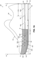
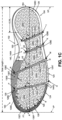
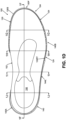
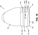
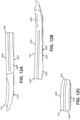
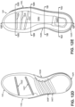
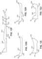
- Figs. 1A-1J provide various views of an article of footwear 100 containing sole structures 104 in accordance with at least some aspects of this technology.
- Fig. 1A provides a medial side view
- Fig. 1B provides a lateral side view
- Fig. 1C provides a bottom view
- Fig. 1D provides a top view
- Fig. 1E provides a rear view
- Fig. 1F provides a longitudinal cross sectional view along line 1F-1F in Fig. 1D
- Fig. 1G provides a transverse cross sectional view along line 1G-1G in Fig. 1D
- Fig. 1H provides a transverse cross sectional view along line 1H-1H in Fig. 1D
- Fig. 1A provides a medial side view
- Fig. 1B provides a lateral side view
- Fig. 1C provides a bottom view
- Fig. 1D provides a top view
- Fig. 1E provides a rear view
- Fig. 1F provides
- Fig. 1I provides a transverse cross sectional view along line 1I-1I in Fig. 1D
- Fig. 1J provides a transverse cross sectional view along line 1J-1J in Fig. 1D
- Figs 2A-2J provide various views of outsole components 120/130 of this example sole structure 104 as follows: Fig. 2A provides a medial side view of outsole components 120/130; Fig. 2B provides a lateral side view; Fig. 2C provides a rear view; Fig. 2D provides a bottom view; Fig. 2E provides a top view; Fig. 2F provides a longitudinal cross sectional view along line 2F-2F in Fig. 2E; Fig.
- FIG. 2G provides a transverse cross sectional view along line 2G-2G in Fig. 2E;
- Fig. 2H provides a transverse cross sectional view along line 2H-2H in Fig. 2E;
- Fig. 2I provides a transverse cross sectional view along line 2I-2I in Fig. 2E;
- Fig. 2J provides a transverse cross sectional view along line 2J-2J in Fig. 2E .
- FIG. 3E provides a top view
- Fig. 3F provides a longitudinal cross sectional view along line 3F-3F in Fig. 3E
- Fig. 3G provides a transverse cross sectional view along line 3G-3G in Fig. 3E
- Fig. 3H provides a transverse cross sectional view along line 3H-3H in Fig. 3E
- Fig. 3I provides a transverse cross sectional view along line 3I-3I in Fig. 3E
- Fig. 3J provides a transverse cross sectional view along line 3J-3J in Fig. 3E
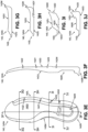
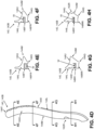
- Figs 4A-4H provide various views of midsole component 140B of this example sole structure 104 as follows: Fig. 4A provides a medial side view of midsole component 140B; Fig.
- Fig. 4B provides a lateral side view
- Fig. 4C provides a bottom view
- Fig. 4D provides a top view
- Fig. 4E provides a transverse cross sectional view along line 4E-4E in Fig. 4D
- Fig. 4F provides a transverse cross sectional view along line 4F-4F in Fig. 4D
- Fig. 4G provides a transverse cross sectional view along line 4G-4G in Fig. 4D
- Fig. 4H provides a transverse cross sectional view along line 4H-4H in Fig. 4D
- Fig. 5 provides a view of a fluid-filled bladder 160 that may be provided in sole structures 104 in accordance with at least some examples of this technology.
- sole structure may include any one or more foot support parts, e.g., forming the entirety and/or a portion of an overall sole for an article of footwear 100.
- foot support parts may include, for example, any individual part and/or combination of two or more foot support parts described in the examples below and shown in the figures.
- Various features, characteristics, and/or parts of example articles of footwear 100 and sole structures 104 thereof are described in more detail below.
- the article of footwear 100 of Fig. 1A includes an upper 102 and a sole structure 104 engaged with the upper 102.
- the upper 102 and sole structure 104 may be engaged together in any desired manner, including in manners conventionally known and used in the footwear arts (such as by one or more of adhesives or cements, stitching or sewing, mechanical connectors, etc.).
- the upper 102 (which may be formed from one or more parts), potentially together with the sole structure 104, defines a foot-receiving interior chamber 106 for containing a wearer's foot.
- the bottom of the upper 102 may include a strobel or other component engaged with or integrally formed with another portion of the upper 102.
- the upper 102 may include other components as well.
- the upper 102 may include a tongue member located across the foot instep area and positioned to moderate the feel of the footwear's closure system on the wearer's foot; a closure system (e.g., including one or more of a lace type closure system, a zippered closure system, a buckle type closure system, elastic stretch elements, etc.); a heel counter; a toe cap; securing straps; etc.
- the upper 102 may include a "sock-like" upper component, e.g., made from fabric and configured to closely fit the wearer's foot like a conventional sock.
- the upper 102 may be made from any desired material(s) and/or in any desired constructions and/or manners without departing from this technology. As some more specific examples, all or at least a portion of the upper 102 (and optionally a majority, substantially all, or even all of the upper 102) may be formed as a woven textile component, a knitted textile component, another textile component, a natural leather component, a synthetic leather component, a polymeric component (e.g., a TPU, etc.), etc.
- the components for upper 102 may have structures and/or constructions like those used in footwear products commercially available from NIKE, Inc. of Beaverton, OR and/or other manufacturers, including conventional structures and constructions as are known and used in the art.
- the upper 102 construction may include uppers having foot securing and engaging structures (e.g., "dynamic” and/or “adaptive fit” structures), e.g., of the types described in U.S. Patent Appln. Publn. No. 2013/0104423.
- uppers 102 and articles of footwear 100 in accordance with this technology may include foot securing and engaging structures of the types used in footwear products commercially available from NIKE, Inc. of Beaverton, Oregon. These types of wrap-around and/or adaptive or dynamic fit structures may at least partially wrap around and securely hold the wearer's foot.
- uppers 102 and articles of footwear 100 in accordance with at least some examples of this technology may include fused layers of upper materials, e.g., uppers of the types that include upper materials bonded by hot melt or other adhesive materials, such as in footwear products commercially available from NIKE, Inc. of Beaverton, Oregon.
- uppers of the types described in U.S. Patent Nos. 7,347,011 and/or 8,429,835 may be used without departing from this technology.
- the sole structure 104 of this illustrated example includes multiple parts, including: (a) a first outsole component 120 (e.g., having conventional hardness and/or coefficient of friction properties), (b) a second outsole component 130 (e.g., having harder and/or reduced coefficient of friction properties as compared to the first outsole component 120); and (c) a midsole component 140 (e.g., made from one or more parts, such as parts 140A and 140B).
- such sole structures 104 may include additional components, e.g., such as one or more decorative components 150, one or more fluid-filled bladders 160, etc.
- the outsole comprises two different components, portions, and/or materials having different properties, namely: first outsole component 120 and second outsole component 130.
- the first outsole component 120 may be formed from a first material having a first hardness, and this first material (and/or first outsole component 120) may form at least a majority of a ground-facing surface 120G of the sole structure 104. In some more specific examples, this first material (and/or this first outsole component 120) may form at least 60%, at least 75%, at least 85%, or even at least 90% of a ground-facing surface 120G of the sole structure 104 (e.g., measured based on overall surface area of the ground-facing surface 120G).
- the outsole of this example further includes a second outsole component 130, e.g., formed from a second material having a second hardness.
- This second hardness e.g., of the second outsole component 130
- This second outsole component 130 has a hardness at least 18 Shore A hardness points higher than a hardness of the material forming a majority of the ground-facing surface 120G of the first outsole component 120.
- the second outsole component 130, the forefoot medial sidewall 130S, and/or a material forming at least a portion (e.g., at least a majority) of the forefoot medial sidewall 130S may have hardness (the "second hardness” mentioned above) at least 15 Shore A hardness points higher, at least 20 Shore A hardness points higher, at least 22 Shore A hardness points higher, or even at least 24 Shore A hardness points higher than the hardness of the first outsole component 120, the ground-facing surface 120G, and/or a material forming at least a majority of the ground-facing surface 120G of the sole structure 104 (the "first hardness" mentioned above).
- the first outsole component 120, the ground-facing surface 120G, and/or a material of at least a majority of the ground-facing surface 120G of the sole structure 104 may be made from a material having a hardness (the "first hardness") between 50 Shore A and 75 Shore A, and in some examples, a hardness between 55 Shore A and 72 Shore A and/or a hardness below 75 Shore A.
- first hardness a hardness between 50 Shore A and 75 Shore A, and in some examples, a hardness between 55 Shore A and 72 Shore A and/or a hardness below 75 Shore A.
- the second sole component 130, the forefoot medial sidewall 130S, and/or a material of at least a portion (e.g., at least a majority) of the forefoot medial sidewall 130S may be made from a material having a hardness (the "second hardness") between 80 Shore A and 110 Shore A, and in some examples, a hardness between 88 Shore A and 100 Shore A and/or a hardness above 85 Shore A.
- This second material (and second outsole component 130) extends from the first material and is engaged with the first material (and first outsole component 120).
- first outsole component 120 and the second outsole component 130 will be fixedly joined together to form a unitary, one-piece construction, e.g., with the first outsole component 120 and the second outsole component 130 joined together by a melt bonded connection, a cross-linked connection, and/or in-molded connection.
- the unitary, one-piece construction can be formed: (a) by placing one or more pre-forms of the second outsole component 130 in a mold (e.g., along at least the medial forefoot side perimeter edge and/or the forward toe sidewall edge), (b) by placing one or more pre-forms of the first outsole component 120 in the mold and in direct contact with the pre-form(s) of the second outsole component 130, and (c) closing the mold (if needed) with application of heat and/or pressure.
- a mold e.g., along at least the medial forefoot side perimeter edge and/or the forward toe sidewall edge
- the pre-form parts are held in the mold for a sufficient time and under sufficient heat and pressure to: (a) shape the pre-forms into the desired shapes (e.g., based on the shape of the mold cavity surfaces), (b) physically join the pre-forms together (e.g., by at least partially melting and contacting the softened/melted materials at their interface, and thereafter solidifying the parts together into a single piece construction), and/or (c) chemically join the pre-forms together (e.g., by cross-linking or other chemical reaction to join (chemically link) atoms of the first outsole component 120 and atoms of the second outsole component 130 to one another across their interface).
- the processes described in U.S. Patent No. 10,226,906 B2 are described in U.S. Patent No. 10,226,906 B2 .
- This type of permanent connection to form a unitary, one-piece outsole component from the first outsole component 120 and the second outsole component 130 can be particularly beneficial for use of the sole structure in various urban dance environments.
- Many urban dance moves produce substantial stress on soles and generate significant forces (including shear forces).
- Outsoles having multiple parts that are joined together only by adhesives and/or cements may have insufficient strength across the adhesive/cement bond to hold together for a significant time and/or for at least some of the desired dance moves.
- at least some example sole structures according to this technology will have melt-bonded and/or cross-linked engagement of components 120, 130 to form a unitary, one-piece construction.
- an outsole component including different hardness in the forefoot ground-facing surface 120G and the forefoot medial sidewall 130S may be formed as a single component (e.g., by molding a single composition) and then at least one of the two portions of the outsole component (e.g., a portion corresponding to first outsole component 120 and/or a portion corresponding to the second outsole component 130) may be treated (e.g., coated with a material, sprayed with a material, irradiated (e.g., with laser or other radiation), etc.) to alter the hardness of one portion with respect to the other portion.
- the second outsole component 130 and/or the second (harder) material thereof forms at least a first portion of an exterior surface of a medial sidewall 130S of the sole structure 104 (e.g., from Point A at a forward toe location to point M at a medial forefoot/midfoot area in Fig. 1C).
- Figs. 1C , 1F-1H , and 2C-2H generally show an interface 122 location between the first outsole component 120 and the second outsole component 130 in accordance with some examples of this technology.
- 1F-1H , and 2C-2H show the second outsole component 130 and its (harder) material extending from the medial midfoot/forefoot location M at least to the forward toe FT region of the overall outsole component (designated at location A in Fig. 1C ).
- the first portion of the exterior surface of the sidewall 130S formed by the second material comprises a forefoot medial sidewall 130S surface that includes at least a majority of a surface area of the exterior surface of the sidewall of the sole structure 104 extending from: (i) a first forward toe location of the sole structure 104 (e.g., Point A) to (ii) a forefoot or midfoot medial side location of the sole structure 104 rearward of a first metatarsal head support region of the sole structure 104 (e.g., rear edge M).
- a first forward toe location of the sole structure 104 e.g., Point A
- a forefoot or midfoot medial side location of the sole structure 104 rearward of a first metatarsal head support region of the sole structure 104 e.g., rear edge M.
- the medial sidewall 130S of the outsole terminates at the rear edge M.
- the second outsole component 130 may originate at rear edge M along the medial sidewall 130S.
- forward of rear edge M at least a majority (and in some examples, at least 60%, at least 75%, at least 80%, at least 85%, at least 90%, at least 95%, or even 100%) of the medial sidewall 130S surface area may be formed of the harder material described above.
- Rear edge M, the second outsole component 130, and/or the medial sidewall 130S having the harder material properties described above may originate at a location forward of 0.4L (measured forward from the rear heel RH vertical plane VP location), and in some examples forward of 0.45L or forward of 0.5 L.
- rear edge M, the second outsole component 130, and/or the medial sidewall 130S having the harder material properties described above may originate at a location between 0.4L and 0.65L, or even between 0.45L and 0.6L.
- rear edge M, the second outsole component 130, and the medial sidewall 130S of the sole structure 104 having the harder material properties described above is located at about 0.51L.
- the second outsole component 130 and the medial sidewall 130S of the sole structure 104 having the harder material properties described above extends to (and beyond) the forward toe location FT (at Point A).
- the second outsole component 130 and/or the medial sidewall 130S of the sole structure 104 having the harder material properties described above may terminate on the medial side of the forward toe location FT, e.g., between 0.85L and 1L, and in some examples, between 0.9L and 0.99L or even between 0.92L and 0.98L.
- the harder material of second outsole component 130 may form all or substantially all of the medial sidewall 130S in the forefoot region of the shoe and even all or substantially all of the medial sidewall of the overall sole structure 104 forward of 0.5L.
- Fig. 1C further shows that the second outsole component 130 and/or the second (harder) material thereof may extend around and form an exterior surface of at least a portion of the lateral sidewall 124 of the sole structure 104 along a forefoot portion of the lateral side of the sole structure 104 (e.g., to locations B, C, and/or D in Fig. 1C ).
- This is shown in Fig. 1C by the broken interface line 122 extending to Points B, C, and D (interface line 122 indicates the interface between outsole components 120 and 130, e.g., melt-bonded and/or cross-linked together, as described above).
- the harder material When present on the lateral sidewall 124 side, the harder material may extend rearward to a location forward of 0.4L (measured forward from the rear heel RH vertical plane VP location), and in some examples forward of 0.45L or forward of 0.5 L. As some additional examples, when present on the lateral sidewall 124 side, the harder material may extend rearward to a location between 0.4L and 0.9L, between 0.45L and 0.8L, or even between 0.48L and 0.75L.
- the harder material of at least the medial sidewall 130S may continue downward in a vertical direction with respect to the sole structure 104 from a top edge of the second outsole component 130 to locations along the bottom (i.e., at the ground contacting surface) of the sole structure 104. As generally shown in Figs.
- the sole structure 104 incudes: (a) a ground-facing surface (including 120G formed from the first outsole component 120); (b) a forefoot medial sidewall 130S extending from a first forward toe location of the sole structure 104 at least to a medial side location M of the sole structure 104 rearward of a first metatarsal head support region of the sole structure 104; and (c) a forefoot lateral sidewall 124 extending from a second forward toe location to a lateral side location D of the sole structure 104 rearward of a fifth metatarsal head support region of the sole structure 104.
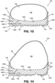
- a medial transition region 130T extends from the ground-facing surface to the forefoot medial sidewall 130S, and this medial transition region 130T includes a first portion having a first curvature.
- a lateral transition region 124T extends from the ground-facing surface to the forefoot lateral sidewall 124, and this lateral transition region 124T includes a corner (e.g., a square corner or a corner within 80 degrees to 105 degrees) or a second curvature.
- the second curvature of the lateral transition region 124T may extend continuously in an anterior-to-posterior direction of the sole structure 104 for a distance of at least 15 mm, and in some examples, at least 20 mm, at least 25 mm, at least 30 mm, at least 40 mm, at least 50 mm, or even at least 60 mm.
- the first curvature of the medial transition region 130T extends continuously in an anterior-to-posterior direction of the sole structure for a distance of at least 20 mm.
- the first curvature and second curvature features may be located within the various sole structure 104 length parameters for the medial sidewall 130L and the lateral sidewall 124 described above (e.g., at a location forward of 0.4L and/or any of the other ranges described above for the material of the lateral sidewall 124 of the first outsole component 120 and/or for the harder material of the sidewall 130S of the second outsole component 130).
- a forward toe sidewall 130F will extend: (a) from the first forward toe location to the second forward toe location and (b) from the forefoot medial sidewall 130S (that includes the harder forefoot medial sidewall surface) to the forefoot lateral sidewall 124.
- the forward toe sidewall 130F connects sidewalls 130S, 124.
- a forward toe transition region 132T extends from the ground-facing surface to the forward toe sidewall 130F.
- the first curvature of the medial transition region 130T will extend over any of the length parameters and/or ranges described above with a curvature greater than a 5 mm radius (and/or in the other curvature ranges described above). If desired, the first curvature of the medial transition region 130T may vary over its length, e.g., get a larger (or less sharp) curvature in the anterior-to-posterior direction. Additionally or alternatively, if desired, in at least some examples of this technology, the second curvature of the lateral transition region 124T will extend over any of the length parameters and/or ranges described above with a corner or a curvature less than a 5 mm radius (and/or in the other angular or curvature ranges described above).
- curvature of the forward toe transition region 132T may vary, e.g., smoothly changing from the curvature of the forward end of the lateral transition region 124T to the curvature of the forward end of medial transition region 130T.
- the curvature of the forward toe transition region 132T may increase (or get less sharp) in a direction from the forefoot lateral sidewall 124/lateral transition region 124T to the forefoot medial sidewall 130S/medial transition region 130T.
- the rounded first curvature of the medial transition region 130T and at least a portion of the forward toe transition region 132T may be useful in various urban dance moves, e.g., as a wearer transitions his/her body weight to concentrate it on the medial side and/or forward toe area(s) of the foot.
- the relatively large and rounded first curvature of the medial transition region 130T allows the weight to transition relatively smoothly and predictably from the ground-facing surface 120G to the medial sidewall 130S as the wearer rolls the foot inward to engage the medial sidewall 130S with the contact surface.
- the relatively large and rounded first curvature of the medial transition region 130T also helps prevent a sudden and abrupt weight transfer to the side of the feet (and sidewall 130S of the second outsole component 130), e.g., to prevent an undesired sudden "tipping point" when transferring weight to the sides of the feet.
- the relatively large and rounded curvature of the forward toe transition region 132T when present, allows the weight to transition relatively smoothly from the ground-facing surface 120G to the forward toe sidewall 130F (and, optionally, from there to the medial sidewall 130S) as the wearer shifts weight toward the forward toe area of the sole structure 104.
- the medial transition region 130T may be formed from the harder rubber composition and/or component described above.
- a portion of the forefoot medial peripheral edge of the ground-facing surface of the outsole may be formed of the harder rubber composition/component, e.g., shown by the broken interface line 122 in Fig. 1C .
- This peripheral edge of the ground-facing surface of the outsole formed of the harder rubber composition and/or component may be at least 2 mm wide, and in some examples, at least 3 mm wide, or even at least 5 mm wide.
- this harder rubber composition/component does not extend too far into the ground-facing surface 120G of the outsole.
- the peripheral edge of the ground-facing surface 120G of the outsole formed of the harder rubber composition/component may be less than 20 mm wide, and in some examples, less than 16 mm wide, or even less than 12 mm wide. These ranges may provide the desired hardness properties at the forefoot side edge(s) of the sole structure 104 for various urban dance moves without making the overall ground facing surface 120G overly (or unnecessarily) hard (and therefore slick).
- Figs. 1A-1J further show that the sole structure 104 includes a midsole 140.
- the midsole 140 may include any number of parts or components without departing from this technology.
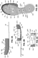
- This illustrated example midsole 140 includes three midsole components: (a) a first (e.g., medial side) midsole component 140A (see also Figs. 3A-3J ), (b) a second (e.g., lateral side) midsole component 140B (see also Figs. 4A-4H ), and (c) a fluid-filled bladder 160 (e.g., as are conventionally known and used in the footwear arts; see also Fig. 5 ).
- the midsole 140 provides support for the wearer's foot, absorbs impact forces, and generally improves the comfort and stability of the footwear 100.
- the first midsole component 140A constitutes the largest midsole component, supporting at least 60% (and in some examples, at least 50%, at least 75%, at least 80%, at least 90%, or even at least 95%) of the plantar surface of a wearer's foot.
- the first midsole component 140A may be made from a polymeric foam material, e.g., as are conventionally known and used in the footwear arts (e.g., ethylvinylacetate (“EVA”) foams, polyurethane foams, etc.).
- EVA ethylvinylacetate
- First midsole component 140A includes an upper-facing surface 142U, a ground-facing surface 142G, a medial sidewall 142M, a lateral side edge 142L, and a rear wall 142R.
- the upper-facing surface 142U may be contoured, e.g., to better support and conform to the shape of a wearer's foot. Additionally, in this illustrated example, the upper-facing surface 142U defines a receptacle 160R for receiving a heel based fluid-filled bladder 160.
- the ground-facing surface 142G of this example includes four relatively deep flexion grooves 142W, 142X, 142Y, and 142Z that extend across the first midsole component 140A in a generally lateral heel-to-medial forefoot direction.
- the flexion grooves 142W to 142Z may extend completely from the medial sidewall 142M to the lateral edge 142L of first midsole component 140A.
- four flexion grooves 142W-142Z are shown in this illustrated example, more or fewer such flexion grooves (optionally oriented in the lateral heel-to-medial forefoot direction) may be included, such as from 2 to 8 such grooves, and optionally, from 3 to 6 such grooves.
- the deep flexion grooves may be, for example, from 3 to 10 mm deep over at least a majority of their lengths (or even at least 60%, at least 70%, or even at least 80% of their lengths) and in some examples, from 4 to 8 mm deep (over any of those length ranges).
- the deep flexion grooves 142W-142Z may be formed in the first midsole component 140A in any desired manner, such as during a molding process (e.g., when the first midsole component 140A is formed by molding), by cutting (e.g., using a blade, laser, etc.), directly formed via a rapid manufacturing process (e.g., a rapid manufacturing additive fabrication technique, a rapid manufacturing subtractive fabrication technique, etc.), etc.
- a molding process e.g., when the first midsole component 140A is formed by molding
- cutting e.g., using a blade, laser, etc.
- directly formed via a rapid manufacturing process e.g., a rapid manufacturing additive fabrication technique, a rapid manufacturing subtractive
- the second midsole component 140B of this illustrated example provides at least a portion of a lateral sidewall 144L and lateral edge support for the sole structure 104 and article of footwear 100. While other proportions are possible, in some examples of this technology, the second midsole component 140B supports less than 40% (and in some examples, less than 50%, less than 25%, less than 20%, less than 10%, or even less than 5%) of the plantar surface of a wearer's foot.
- the second midsole component 140B may be made from a polymeric foam material, e.g., as are conventionally known and used in the footwear arts (e.g., ethylvinylacetate ("EVA") foams, polyurethane foams, etc.).
- EVA ethylvinylacetate
- the material of the second midsole component 140B may differ from the material of the first midsole component 140A, e.g., in hardness, resilience, other performance properties, composition, etc., although this is not a requirement in all examples of this technology
- Second midsole component 140B of this example includes an upper-facing surface 144U, a ground-facing surface 144G, the lateral sidewall 144L, and a medial side edge 144M.
- the upper-facing surface 144U may be contoured, e.g., to better support and conform to the shape of a wearer's foot. Additionally, in this illustrated example, the upper-facing surface 144U and/or the medial side edge 144M define a portion of a receptacle 162R (e.g., cooperating with the receptacle 160R formed in the first midsole component 140A) for receiving the heel based fluid-filled bladder 160.
- first midsole component 140A and/or second midsole component 140R may be defined in first midsole component 140A and/or second midsole component 140R (or other sole structure 104 component).
- Figs. 4B through 4D further show that the lateral sidewall 144L of the second midsole component 140B of this example includes structures 144X and 144Y (e.g., recesses or the like) for receiving surfaces of the outsole (e.g., the forefoot lateral sidewall 124 of first outsole component 120).
- Fig. 1B shows the forefoot lateral sidewall 124 engaged with surfaces of the lateral sidewall 144L of the second midsole component 140B that include the structures 144X and 144Y.
- first midsole component 140A and second midsole component 140B include grooves 142D and 144D, respectively, for receiving the optional decorative element 150.
- the decorative element 150 includes an elongated bead of TPU having a different color from the first midsole component 140A and second midsole component 140B.
- Other or different decorative structures and elements may be provided, if desired.
- the first feature relates to the forefoot lateral sidewall 124 of first outsole component 120.
- this example forefoot lateral sidewall 124 comprises: (a) a rear top edge 124RT, (b) a rear side edge 124RS extending downward from the rear top edge 124RT, (c) a forward top edge 124FT, (d) a forward side edge 124FS extending downward from the forward top edge 124FT, and (e) an intermediate top edge 1241 extending from the rear side edge 124RS to the forward side edge 124FS.
- the rearmost edge 124E of the forefoot lateral sidewall 124 may be located within a range of 0.35L to 0.65L, and in some examples, between 0.4L and 0.6L.
- the rear side edge 124RS of the forefoot lateral sidewall 124 may be located within a range of 0.45L to 0.75L, and in some examples, between 0.5L and 0.7L.
- the forward side edge 124FS may be located within a range of 0.7L and 0.95L, and in some examples, between 0.75L and 0.92L.
- top edge 124RT, 124FT, 124I features and side edge 124RS, 124FS features of forefoot lateral sidewall 124 in this illustrated example form a gap in the lateral sidewall 124 between the rear side edge 124RS and the forward side edge 124FS.
- the midsole component 140 (and in this illustrated example, second midsole component 140B) is exposed in this gap. More specifically, as shown in Fig.
- an exterior surface of the lateral sidewall 144L of the midsole 140 (second midsole component 140B) is exposed at an exterior surface of the sole structure 104, e.g., extending above the intermediate top edge 1241 and from the rear side edge 124RS to the forward side edge 124FS.
- the lateral sidewall 144L of midsole 140 (midsole component 140B in this example) also is exposed rearward of rearmost edge 124E in this illustrated example sole structure 104.
- the lateral sidewall 144L of the midsole component 140 in this example includes further features to assist in providing desired levels of flexibility and support, e.g., for urban dance uses.
- one or more cutouts 144C are defined in the top edge 144T of the midsole 140 (e.g., second midsole component 140B). While four such cutouts 144C are shown in these figures, any desired number of cutouts 144C may be provided, including from 1 to 8 cutouts 144C, and in some examples, from 2 to 6 such cutouts 144C.
- the individual cutouts 144C may be at least 2 mm wide (in the anterior-to-posterior direction), and in some examples, from 2 mm to 15 mm wide, from 2.5 mm to 12 mm wide, or even from 3 mm to 8 mm wide.
- the individual cutouts 144C may be at least 2 mm tall (in the top-to-bottom direction), and in some examples, from 2 mm to 20 mm tall, from 3 mm to 16 mm tall, or even from 4 mm to 12 mm tall.
- the cutouts may have the same or different sizes, shapes, etc.
- a sole structure 104 according to some examples of this technology may include any one or more of the above noted cutouts 144C, and/or the cutout(s) may be provided in any one or more of the positions and/or ranges of positions described in more detail below.
- Fig. 1B (a) at least a portion of the rearmost lateral sidewall cutout 144C in the lateral sidewall 144L of midsole 140 is located at about 0.65L, (b) at least a portion of the next forward or rear intermediate lateral sidewall cutout 144C is located at about 0.71L, (c) at least a portion of the next forward or forward intermediate lateral sidewall cutout 144C is located at about 0.77L, and (d) at least a portion of the forwardmost lateral sidewall cutout 144C is located at about 0.83C.
- Other longitudinal arrangements and/or spacings of cutouts 144C are possible without departing from this technology.
- at least some portions of one or more lateral sidewall 144L cutouts 144C may be located within the various ranges shown in Table 1 below.
- the medial sidewall 130S may include cutouts 130C (or other recesses). These medial side cutouts 130C may be similar in size, shape, and/or location to the cutouts 144C provided in the lateral sidewall 144L. As more specific examples, as shown in Figs. 1A and 2A , at this medial sidewall 130S, one or more cutouts 130C are defined in the top edge 130E of the second outsole component 130.
- any desired number of cutouts 130C may be provided, including from 1 to 8 cutouts 130C, and in some examples, from 2 to 6 such cutouts 130C.
- the individual cutouts 130C may be at least 2 mm wide (in the anterior-to-posterior direction), and in some examples, from 2 mm to 15 mm wide, from 2.5 mm to 12 mm wide, or even from 3 mm to 8 mm wide.
- the individual cutouts 130C may be at least 2 mm tall (in the top-to-bottom direction), and in some examples, from 2 mm to 20 mm tall, from 3 mm to 16 mm tall, or even from 4 mm to 12 mm tall.
- a sole structure 104 may include any one or more of the above noted cutouts 130C, and/or the cutout(s) 130C may be provided in any one or more of the positions and/or ranges of positions described in more detail below.
- Fig. 1A (a) at least a portion of the rearmost medial sidewall cutout 130C in the medial sidewall 130S of second outsole component 130 is located at about 0.65L, (b) at least a portion of the next forward or rear intermediate medial sidewall cutout 130C is located at about 0.71L, (c) at least a portion of the next forward or forward intermediate medial sidewall cutout 130C is located at about 0.77L, and (d) at least a portion of the forwardmost medial sidewall cutout 130C is located at about 0.83C.
- Other longitudinal arrangements and/or spacings of cutouts 130C are possible without departing from this technology.
- at least some portions of one or more medial sidewall 130S cutouts 130C may be located within the various ranges shown in Table 1 below.
- the ground-facing surface 142G of the midsole 140 (and first midsole component 140A in the illustrated example) includes one or more relatively deep flexion grooves 142W, 142X, 142Y, and 142Z that extend across (e.g., completely across) the first midsole component 140A in a generally lateral heel-to-medial forefoot direction. Additional features of the sole structure 104 may combine with these flexion grooves 142W-142Z to enhance desired flexibility and support various urban dance moves. For example, as shown in Figs.
- the outsole component (e.g., either or both of outsole components 120, 130) may have at least one slit defined completely through it (from its upper-facing surface to its ground-facing surface 120G) that extends from an outermost lateral perimeter side edge of the outsole component (e.g., first outsole component 120) toward but not completely to the forefoot medial sidewall 130S outer surface.
- the first outsole component 120 includes two slits 126A and 126B (with slit 126A forward of slit 126B).
- the overall outsole includes a forward outsole component part 128 (formed as a single piece including first outsole component 120 and second outsole component 130 fixed together) that extends from the forwardmost toe FT location to a rearmost end 128E or rear edge located generally in the midfoot region of the overall sole structure 104.
- the slit(s) 126A and/or 126B may extend in a generally lateral heel-to-medial forefoot direction for any desired distance.
- either or both of the slit(s) 126A and/or 126B may have a length dimension of at least 50 mm inward from the lateral perimeter edge of the outsole to their closed ends 126E, and in some examples, at least 40 mm, at least 60 mm, at least 75 mm, at least 80 mm, at least 90 mm, or even at least 100 mm.
- the closed end(s) 126E will be located less than 25 mm (and in some examples, less than 20 mm, less than 15 mm, or even less than 10 mm) from the medial sidewall 130S).
- the outsole of this example further includes: (a) an intermediate outsole component part 128B, e.g., located rearward and spaced from the forward outsole component part 128 by a first gap 128G1 and (b) a rearward outsole component part 128C, e.g., located rearward and spaced from the intermediate outsole component part 128B by a second gap 128G2. More or fewer outsole component parts may be included in an overall sole structure 104, if desired (e.g., two or more of parts 128, 128B, and/or 128C may be formed or joined together as a single part (e.g., joined at either or both perimeter edges, etc.)).
- an intermediate outsole component part 128B e.g., located rearward and spaced from the forward outsole component part 128 by a first gap 128G1
- a rearward outsole component part 128C e.g., located rearward and spaced from the intermediate outsole component part 128B by a second gap
- the slits 126A, 126B, and gaps 128G1 and 128G2 of the outsole are located to vertically align with the grooves 142Z, 142Y, 142X, and 142W, respectively, of the midsole 140 (first midsole component 140A, in this illustrated example).
- the ground-facing surface 142G of the midsole 140 is visible and exposed at the bottom of the sole structure 104 in the slits 126A, 126B, and the gaps 128G1, 128G2, as shown in Fig. 1C .
- the ground facing surface 144G of the second midsole component 140B (when present) also may be visible and exposed at the bottom of the sole structure in at least some of the slits 126A, 126B, and/or the gaps 128G1, 128G2.
- the midsole grooves (e.g., 142W to 142Z) have the following features: (a) rearmost flexion groove's lateral edge (e.g., shown by star I) is located at 0.24L, (b) rearmost flexion groove's medial edge (e.g., shown by star J) is located at 0.32L, (c) rear intermediate flexion groove's lateral edge (e.g., shown by star K) is located at 0.36L, (d) rear intermediate flexion groove's medial edge (e.g., shown by star L) is located at 0.44L, (e) forward intermediate flexion groove's lateral edge (e.g., shown by star M) is located at 0.5L, (f) forward intermediate flexion groove's medial edge (e.g., shown by star N) is located at 0.63L, (g) forwardmost flexion groove's lateral edge (e.g., shown by star O) is located at 0.72L, and
- the outsole may have the following features: (a) rear outsole component part 128C's forward lateral edge (e.g., shown by star I) is located at 0.24L, (b) rear outsole component part 128C's forward medial edge (e.g., shown by star J) is located at 0.32L, (c) middle outsole component part 128B's forward lateral edge (e.g., shown by star K) is located at 0.36L, (d) middle outsole component part 128B's forward medial edge (e.g., shown by star L) is located at 0.44L, (e) rear outsole slit 126B's lateral edge (e.g., shown by star M) is located at 0.5L, (f) rear outsole slit 126B's medial edge at closed end 126E (e.g., shown by star N) is located at 0.63L, (g) forward outsole slit 126A's
- the midsole grooves 142W to 142Z, slits 126A, 126B, and outsole gaps 128G1, 128G2 generally are angled with respect to the sole length dimension L (which is oriented perpendicular to and extending directly between the vertical planes VP located at the rear heel RH and forward toe FT locations).
- L which is oriented perpendicular to and extending directly between the vertical planes VP located at the rear heel RH and forward toe FT locations.
- groove 142W and/or gap 128G2 is/are oriented at an angle of about 111 degrees from the L direction (angle A1)
- groove 142X and/or gap 128G1 is/are oriented at an angle of about 111 degrees from the L direction (angle A2)
- groove 142Y and/or slit 126B is/are oriented at an angle of about 115 degrees from the L direction (angle A3)
- groove 142Z and/or slit 126A is/are oriented at an angle of about 104 degrees from the L direction (angle A4).
- these angles may be within the various ranges shown in Table 1 below. These angles, slits, gaps, and discrete parts help provide desired flexibility and foot support for the overall sole structure 104, e.g., for various urban dance moves and uses.
- the midsole component 140 (and in the illustrated example, the second (or lateral side) midsole component 140B) includes a plurality of relatively deep, inwardly extending slits in the lateral wall 144L.
- a first forefoot slit 148F1 is shown in Figs. 1G, 1H , 4E, and 4F
- a first rear slit 148R1 is shown in Figs. 1E , 1I , 1J , 4G, and 4H .
- a second forefoot slit 148F2 and a second rear slit 148R2 may be provided in the lateral wall 144L. While the second slits 148F2 and/or 148R2 may be defined completely in the material of the midsole component 140 (like slits 148F1 and 148R1 are defined in midsole component 140B), in the illustrated example, the ground-facing surface 144G of the second midsole component 140B includes recessed surfaces 148FR and 148RR, and the slits 148F2 and/or 148R2 are defined between the recessed surfaces 148FR and 148RR and the upper-facing surface 142U of the first midsole component 140A or another sole component, such as first outsole component 120 (e.g., Figs.
- slit 148F2 is defined in part between the recessed surface 148FR of the second midsole component 140B and the upper-facing surface of the first outsole component 120 along the extreme lateral edge of the sole structure 104). Any number of these relatively deep, inwardly extending slits may be included in a sole structure 104 and/or midsole 140 without departing from this technology. In the illustrated example, slits 148F2 and 148R2 are spaced vertically below slits 148F1 and 148R1, respectively.
- the lateral sidewall 144 extends at least from a heel region to a midfoot region of the sole structure 104, and the inwardly extending slit 148R1 and/or inwardly extending slit 148R2 is/are defined in the lateral sidewall 144 (or between surfaces of sole structure components 104) extending continuously from the heel region to the midfoot region. Additionally or alternatively, the lateral sidewall 144 extends at least in a forefoot region of the sole structure 104, and the inwardly extending slit 148F1 and/or inwardly extending slit 148F2 is/are defined in the lateral sidewall 144 (or between surfaces of sole structure components 104) extending continuously in the forefoot region.
- the forefoot inwardly extending slits 148F1 and/or 148F2 may be formed as part of the same individual sole structure 104 component(s) as the rear inwardly extending slits 148R1 and/or 148R2 (and the lateral sidewall 144 containing/defining them), or they may be formed in or defined by different sole structure 104 components or parts.
- the slits 148F1, 148F2, 148R1, and/or 148R2 are relatively deep.
- one or more of the slits 148F1, 148F2, 148R1, and/or 148R2 may extend inward (dimension W in Figs. 4E-4H ) for at least 6 mm, and in some examples, at least 8 mm, between 6 mm and 20 mm, between 8 mm and 15 mm, etc.).
- the height dimension may be less than the width dimension, e.g., less than 5 mm, less than 3 mm, or even less than 2 mm.
- the width dimension W and the height dimension may vary over an overall length of the individual slits 148F1, 148F2, 148R1, and/or 148R2.
- the W/H ratio at a specific location along the slit(s) 148F1, 148F2, 148R1, and/or 148R2 may be within a range of: 3 to 20, 4 to 16, and/or even 5 to 12.
- This W/H ratio may be applicable over at least a majority of the length of the slit(s) 148F1, 148F2, 148R1, and/or 148R2, and in some examples, over at least 60%, at least 75%, at least 80%, at least 90%, at least 95%, or even over 100% of the length of the slit(s) 148F1, 148F2, 148R1, and/or 148R2.
- FIG. 1B (a) rear slit(s) 148R1 and/or 148R2 rear origin point is/are shown at line 200 located at 0.03L, (b) rear slit(s) 148R1 and/or 148R2 forward origin point is/are shown at line 202 located at 0.51L, (c) forefoot slit(s) 148F1 and/or 148F2 rear origin point is/are shown at line 204 located at 0.57L, and (d) forefoot slit(s) 148F1 and/or 148F2 forward origin point is/are shown at line 206 located at 0.87L.
- these slit origin points may be located within the various ranges shown in Table 1 below.
- the width dimension W controls the proportion of the lateral edge of the foot that benefits from the presence of the slit(s) 148F1, 148F2, 148R1, and/or 148R2.
- the vertical height of the slit(s) 148F1, 148F2, 148R1, and/or 148R2 control the extent of vertical displacement and/or impact force attenuation (e.g., when the slit fully collapses, impact force is attenuated due to the interfacing surfaces of the midsole 140 at the top and bottom of the slit(s)).
- the medial side may include one or more similar relatively deep inwardly extending slits of this type, e.g., having any of the dimensional and/or locational features described for slits 148F1, 148F2, 148R1 and/or 148R2.
- Table 1 Parameter Value A Value B Value C Rearmost Medial Sidewall Cutout 130C Location* Between 0.55L and 0.75L Between 0.6L and 0.7L Between 0.62L and 0.68L Rear Intermediate Medial Sidewall Cutout 130C Location* Between 0.61L and 0.81L Between 0.66L and 0.76L Between 0.68L and 0.74L Forward Intermediate Sidewall Cutout 130C Location* Between 0.67L and 0.87L Between 0.71L and 0.83L Between 0.73L and 0.81L Forwardmost Medial Sidewall Cutout 130C Location* Between 0.73L and 0.93L Between 0.78L and 0.89L Between 0.8L and 0.87L Rearmost Lateral Sidewall Cutout 144C Location* Between 0.55L and 0.75L Between 0.6L and 0.7L Between 0.62L and 0.68L Rear Intermediate Lateral Sidewall Cutout 144C Location* Between 0.55L and 0.75L Between 0.6L and 0.7L Between 0.62L and 0.68L Rear Intermediate Lateral Sidewall Cutout 144C Location* Between 0.55L and 0.75L Between
- Such sole structures including one or more sole components with a plurality of flexure promoting structures having any one or more of the properties and/or parameter values set forth in in Table 1 above further may include outsole component(s) having the combination of two different outsole hardness (and therefore slickness) features described above and/or any of the structures described above providing these different outsole hardness (and therefore slickness) features.
- the "first curvature" of the medial transition region 130T in sole structures 104 extends in the anterior-to-posterior direction of the sole structure 104 for at least 25 mm, at least 30 mm, at least 35 mm, at least 40 mm, at least 50 mm, at least 60 mm, at least 70 mm, or even at least 80 mm.
- the "corner" or “second curvature” of the lateral transition region 124T in sole structures 104 in accordance with at least some aspects of this technology may extend continuously in the anterior-to-posterior direction of the sole structure for a distance of at least 25 mm, at least 30 mm, at least 35 mm, at least 40 mm, at least 50 mm, at least 60 mm, at least 70 mm, or even at least 80 mm.
- the first curvature of the medial transition region 130T is greater than a 5 mm radius (and in some examples, greater than a radii of at least 5.5 mm, at least 6 mm, and/or even at least 6.5 mm) over any of the above noted distance ranges and/or between any of the noted sets of parallel planes
- the corner or the second curvature of the lateral transition region 124T may be less than a 5 mm radius (and in some examples, less than a radii of 4.75 mm, 4.5 mm, or even 4.25 mm) over any of the above noted distance ranges and/or between any of the noted sets of parallel planes.
- a “transition region” may be considered the region of a sole around its edge from the bottom surface to the sidewall surface of sole component 104 (e.g., from surface 120G to the sidewall surface(s) 124 and/or 130S of the sole component 104).
- the "transition region” may be determined as the region between the location of the sole structure 104 where: (a) a first tangent to the sidewall surface becomes more horizontal than vertical (moving downward from the top of the sidewall surface) and (b) a second tangent to the sidewall surface (at the same transverse cross sectional location) becomes more vertical than horizontal (moving upward from the bottom of the sole surface). If a specific sole structure design has a designed in, determinable, and/or measurable radius for a given cross sectional location on the sole structure 104 (e.g., from a CAD file design), that radius will correspond to the sole structure 104's radius at that transition region location. In that event, the designed in, determined, and/or measured radius can be compared to the predetermined radius of interest to see if the designed in, determined, and/or measured radius is greater than or less than the predetermined radius of interest.
- Fig. 6A illustrates how a "transition region" can be located (e.g., if needed for a specific sole structure) and/or how it can be determined whether the "curvature" of that transition region is greater than or less than a predetermined radii (e.g., if needed for a specific sole structure transition region).
- the ground-facing surface 120G of a sole structure 104 is oriented on a horizontal base surface S with the transverse cross sectional location of the sole structure 104 at the plane location where measurement is desired.
- a circle with the radius of interest R (e.g., corresponding to the radius of curvature limitation being considered) is defined having a downward vertical radius point RD and a horizontally sideways radius point RS.
- a central 45 degree arc is located between the downward radius point RD and the sideways radius point RS, shown as the arc between points Y and Z in Fig. 6A .
- This 45 degree arc represents a "transition area" between the locations on the circle where an upper tangent to the arc becomes more horizontal than vertical (at point Y) and a lower tangent to the arc becomes more vertical than horizontal (at point Z). If the center of the central 45 degree arc (Point X) can be located on the outer surface of the sole structure and the entire surface of the sole structure lies on the central 45 degree arc between points Y and Z, then the transition region of that sole structure has the predetermined radius R.
- the transition region of that sole structure has a curvature that is less than the predetermined radius R. If the sole structure surface extends outside the central 45 degree arc within the transition region of the sole structure, then that sole structure has a curvature greater than the predetermined radius.
- the surface of the sole structure may be considered as a smoothed surface joining the outer surfaces of the raised nubs or ridges.
- Fig. 6B illustrates some more specific example radii provided along the medial transition region 130T and the lateral transition region 124T in sole structures 104 in accordance with one example of this technology.
- the transition region curvature may vary in the posterior-to-anterior direction.
- the forward toe transition region 132T may vary, e.g., bridging the differences in curvature between the medial sidewall 130S and the lateral sidewall 124.
- Sole structures may include one or more sole components having any one or more of the medial transition region and/or lateral transition region properties and/or parameter values set forth in in Table 3 above. Such sole structures further may include outsole component(s) having the combination of two different outsole hardness (and therefore slickness) features described above, any of the structures described above providing these different outsole hardness (and therefore slickness) features, and/or any one or more of the properties described above in conjunction with Table 1.
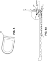
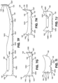
- Figs. 7A-9J show various views of an alternative sole structure 104 and component parts thereof in accordance with some examples of this technology. More specifically, Figs. 7A-7J show various views of an overall sole structure 104, while Figs. 8A-8J provide various views of the outsole structure (e.g., including outsole component parts 120 and 130) and Figs. 9A-9J provide various views of a midsole structure (e.g., including component part 140).
- the same reference number is used in Figs. 7A-9J as those used in Figs. 1A-6B , the same or similar parts are being referred to, and much of the overlapping and/or redundant disclosure is omitted from the discussion of Figs. 7A-9J .
- the sole structure 104 of Figs. 7A-9J may have any of the component parts, features, options, properties, materials, alternatives, additions, and/or the like as described above for the similar sole structure 104 and/or component parts (e.g., 120, 130, 140, 150, 160, etc.) in Figs. 1A-6B . Additionally or alternatively, the sole structure 104 and/or the component parts (e.g., 120, 130, 140, 150, 160, etc.) thereof shown in Figs. 7A-9J may have any one or more and/or any combination of the features described above in Tables 1, 2, and/or 3.
- FIG. 7A-9J also may be engaged with a footwear upper, e.g., having any of the various materials, structures, properties, parts, features, options, alternatives, additions, etc., as described above for the upper 102 shown in Figs. 1A-1J .
- Fig. 7A provides a medial side view of sole structure 104
- Fig. 7B provides a lateral side view
- Fig. 7C provides a bottom view
- Fig. 7D provides a top view
- Fig. 7E provides a rear view
- Fig. 7F provides a longitudinal cross sectional view along line 7F-7F in Fig. 7D
- Fig. 7G provides a transverse cross sectional view along line 7G-7G in Fig. 7D
- Fig. 7H provides a transverse cross sectional view along line 7H-7H in Fig. 7D
- Fig. 7A provides a medial side view of sole structure 104
- Fig. 7B provides a lateral side view
- Fig. 7C provides a bottom view
- Fig. 7D provides a top view
- Fig. 7E provides a rear view
- Fig. 7F provides a longitudinal cross sectional view along line 7F-7F in Fig. 7D
- Fig. 7G provides
- Fig. 7I provides a transverse cross sectional view along line 7I-7I in Fig. 7D ; and Fig. 7J provides a transverse cross sectional view along line 7J-7J in Fig. 7D .
- Fig. 8A provides a medial side view of outsole component (including first and second outsole components 120 and 130); Fig. 8B provides a lateral side view; Fig. 8C provides a rear view; Fig. 8D provides a bottom view; Fig. 8E provides a top view; Fig. 8F provides a longitudinal cross sectional view along line 8F-8F in Fig. 8E ; Fig. 8G provides a transverse cross sectional view along line 8G-8G in Fig. 8E ; Fig.
- FIG. 8H provides a transverse cross sectional view along line 8H-8H in Fig. 8E ;
- Fig. 8I provides a transverse cross sectional view along line 8I-8I in Fig. 8E ;
- Fig. 8J provides a transverse cross sectional view along line 8J-8J in Fig. 8E .
- Fig. 9A provides a medial side view of midsole component 140;
- Fig. 9B provides a lateral side view;
- Fig. 9C provides a rear view;
- Fig. 9D provides a bottom view;
- Fig. 9E provides a top view;
- Fig. 9F provides a longitudinal cross sectional view along line 9F-9F in Fig. 9E;
- Fig. 9A provides a medial side view of midsole component 140;
- Fig. 9B provides a lateral side view;
- Fig. 9C provides a rear view;
- Fig. 9D provides a bottom view;
- FIG. 9G provides a transverse cross sectional view along line 9G-9G in Fig. 9E;
- Fig. 9H provides a transverse cross sectional view along line 9H-9H in Fig. 9E;
- Fig. 9I provides a transverse cross sectional view along line 9I-9I in Fig. 9E;
- Fig. 9J provides a transverse cross sectional view along line 9J-9J in Fig. 9E .
- Figs. 1A-6B includes two separate midsole components 140A (e.g., Figs. 3A-3J ) and 140B (e.g., Figs. 4A-4J) that are joined together along generally longitudinally extending sides 142L and 144M.
- One potential advantage of this multi-piece 140A, 140B midsole 140 construction relates to removing the midsole components from their mold(s). Because of the relatively deep, molded slits 148R1 and/or 148F1 provided in midsole component 140B (e.g., see Figs.
- the two part 140A, 140B midsole component 140 allows the midsole components 140A and/or 140B to be formed as separate parts, which may allow the parts 140A, 140B to be more easily removed from a mold in which it/they are formed.
- a single midsole component 140 is provided in the example sole structure 104 of Figs. 7A-9J . Compare Figs. 9A-9J with Figs. 3A-3H .
- the one-piece midsole component 140 of the example of Figs. 7A-9J extends from the lateral side to the medial side of the sole structure 104 and/or extends to support an entire plantar surface of a wearer's foot.
- the side slits 148F1 and/or 148R1 may extend a shorter distance into the sidewall of the midsole component 140.
- 4E-4H is described as being at least 6 mm, and in some examples, at least 8 mm, between 6 mm and 20 mm, between 8 mm and 15 mm, etc., in the example of Figs. 7G-7J and 9G-9J , the corresponding dimension W of side slits 148F1 and/or 148R1, if present at all, may be within a range of 0 mm to 6 mm, and in some examples, from 0.5 mm to 5.5 mm, or even within a range from 1 mm to 5 mm.
- the width dimension W and the height dimension may vary over an overall length of the individual slits 148F1 and/or 148R1 of the example of Figs. 7A-9J .
- the W/H ratio at a specific location along the slit(s) 148F1 and/or 148R1 of Figs. 7A-9J be within a range of: 1 to 10, 1.5 to 8, and/or even 1.75 to 6.
- This W/H ratio may be applicable over at least a majority of the length of the slit(s) 148F1 and/or 148R1, and in some examples, over at least 60%, at least 75%, at least 80%, at least 90%, at least 95%, or even over 100% of the length of the slit(s) 148F1 and/or 148R1. While not a requirement, in the specific example illustrated in Figs. 7A-9J , the side slits 148F2 and 148R2 defined between the midsole 140 and first outsole component 120 are omitted (compare Figs. 1G-1J with Figs. 7G-7J ).
- the example sole structure 104 of Figs. 7A-9J also differs from those described above by eliminating the rearwardly spaced portion of the lateral sidewall 124 of the outsole located in the midfoot area of the sole structure 104.
- the lateral sidewall 124 segment between rearmost edge 124E and rear side edge 124RS in Figs. 1B , 2B , 2C , and 2E ) is omitted in this alternative sole structure 104.
- the forefoot side slit 148F1 and rearfoot side slit 148R1 in the example of Figs.
- the elimination of the midfoot portion of the lateral sidewall 124 as shown in this example may impact the flexion characteristics of the outsole (including first and second outsole components 120 and 130), the sole structure 104, and/or any shoe containing these parts.
- the outsole (including first and second outsole components 120 and 130) of Figs. 7A-8J includes three medial sidewall 130S cutouts 130C in the forefoot region rather than the four cutouts 130C shown in Figs. 1A-6B .
- These cutouts 130C may be located within any of the positional ranges and/or have any of the structural characteristics described above for the similar cutouts 130C of the example of Figs. 1A-6B .
- the elimination of one or more cutouts 130C also may impact the flexion characteristics of the outsole (including first and second outsole components 120 and 130), the sole structure 104, and/or any shoe containing these parts.
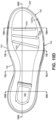
- Figs. 10A-12J show various views of another alternative sole structure 104 and component parts thereof in accordance with some examples of this technology. More specifically, Figs. 10A-10K show various views of an overall sole structure 104, while Figs. 11A-11K provide various views of the outsole structure (e.g., including component parts 120 and 130) and Figs. 12A-12J provide various views of a midsole structure (e.g., including component part 140).
- the same reference number is used in Figs. 10A-12J as those used in Figs. 1A-9J , the same or similar parts are being referred to, and much of the overlapping and/or redundant disclosure is omitted from the discussion of Figs. 10A-12J .
- the sole structure 104 of Figs. 10A-12J may have any of the component parts, features, options, properties, materials, alternatives, additions, and/or the like as described above for the similar sole structure 104 and/or component parts (e.g., 120, 130, 140, 150, 160, etc.) in Figs. 1A-9J . Additionally or alternatively, the sole structure 104 and/or the component parts (e.g., 120, 130, 140, 150, 160, etc.) thereof shown in Figs. 10A-12J may have any one or more and/or any combination of the features described above in Tables 1, 2, and/or 3.
- 10A-12J also may be engaged with a footwear upper, e.g., having any of the various materials, structures, properties, parts, features, options, alternatives, additions, etc., as described above for the upper 102 shown in Figs. 1A-1J .
- Fig. 10A provides a medial side view of sole structure 104
- Fig. 10B provides a lateral side view
- Fig. 10C provides a bottom view
- Fig. 10D provides a top view
- Fig. 10E provides a rear view
- Fig. 10F provides a front view
- Fig. 10G provides a longitudinal cross sectional view along line 10G-10G in Fig. 10D
- Fig. 10H provides a transverse cross sectional view along line 10H-10H in Fig. 10D
- Fig. 10A provides a medial side view of sole structure 104
- Fig. 10B provides a lateral side view
- Fig. 10C provides a bottom view
- Fig. 10D provides a top view
- Fig. 10E provides a rear view
- Fig. 10F provides a front view
- Fig. 10G provides a longitudinal cross sectional view along line 10G-10G in Fig. 10D
- Fig. 10H provides a transverse
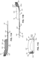
- Fig. 11A provides a medial side view of outsole component (including first and second outsole components 120 and 130); Fig. 11B provides a lateral side view; Fig. 11C provides a rear view; Fig. 11D provides a bottom view; Fig. 11E provides a top view; Fig. 11F provides a longitudinal cross sectional view along line 11F-11F in Fig. 11E ; Fig.
- FIG. 11G provides a transverse cross sectional view along line 11G-11G in Fig. 11E ;
- Fig. 11H provides a transverse cross sectional view along line 11H-11H in Fig. 11E ;
- Fig. 11I provides a transverse cross sectional view along line 111-111 in Fig. 11E ;
- Fig. 11J provides a transverse cross sectional view along line 11J-11J in Fig. 11E ;
- Fig. 11K provides a view explaining additional features of some examples of this technology.
- Fig. 12A provides a medial side view of midsole component 140;
- Fig. 12B provides a lateral side view;
- Fig. 12C provides a rear view;
- Fig. 12D provides a bottom view;
- Fig. 12A provides a medial side view of midsole component 140;
- Fig. 12B provides a lateral side view;
- Fig. 12C provides a rear view;
- Fig. 12D
- FIG. 12E provides a top view
- Fig. 12F provides a longitudinal cross sectional view along line 12F-12F in Fig. 12E
- Fig. 12G provides a transverse cross sectional view along line 12G-12G in Fig. 12E
- Fig. 12H provides a transverse cross sectional view along line 12H-12H in Fig. 12E
- Fig. 12I provides a transverse cross sectional view along line 12I-12I in Fig. 12E
- Fig. 12J provides a transverse cross sectional view along line 12J-12J in Fig. 12E .
- the outsole comprises two different components, portions, and/or materials having different properties, namely: first outsole component 120 and second outsole component 130.
- the first outsole component 120 may be formed from a first material having a first hardness, and this first material (and/or first outsole component 120) may form at least a portion (e.g., at least a majority) of a ground-facing surface 120G of the sole structure 104.
- this first material (and/or this first outsole component 120) may form at least 60%, at least 75%, at least 85%, or even at least 90% of a ground-facing surface 120G of the sole structure 104 (e.g., measured based on overall surface area of the ground-facing surface 120G of the total outsole).
- First outsole component 120 may have any of the features, options, and/or alternatives described above for first outsole components 120 of Figs. 1A-9J .
- the outsole of this example further includes a second outsole component 130, e.g., formed from a second material having a second hardness.
- This second hardness (e.g., of the second outsole component 130) forms at least a portion of the forefoot medial sidewall 130S of the sole structure 104.
- This second outsole component 130 has a hardness at least 15 Shore A hardness points higher than a hardness of the material forming a majority of the ground-facing surface 120G of the first outsole component 120.
- the second outsole component 130, at least a portion of the forefoot medial sidewall 130S, and/or a material forming at least a portion of the forefoot medial sidewall 130S may have hardness (the "second hardness” mentioned above) at least 18 Shore A hardness points higher, at least 20 Shore A hardness points higher, at least 22 Shore A hardness points higher, or even at least 24 Shore A hardness points higher than the hardness of the first outsole component 120, the ground-facing surface 120G, and/or a material forming at least a majority of the ground-facing surface 120G of the sole structure 104 (the "first hardness" mentioned above).
- Second outsole component 130 may have any of the features, options, and/or alternatives described above for second outsole components 130 of Figs. 1A-9J .
- the first outsole component 120, the ground-facing surface 120G, and/or a material of at least a majority of the ground-facing surface 120G of the sole structure 104 may be made from a material having a hardness (the "first hardness") between 50 Shore A and 75 Shore A, and in some examples, a hardness between 55 Shore A and 72 Shore A and/or a hardness below 75 Shore A.
- first hardness a hardness between 50 Shore A and 75 Shore A, and in some examples, a hardness between 55 Shore A and 72 Shore A and/or a hardness below 75 Shore A.
- the second sole component 130, at least a portion of the forefoot medial sidewall 130S, and/or a material of at least a portion of the forefoot medial sidewall 130S may be made from a material having a hardness (the "second hardness") between 80 Shore A and 110 Shore A, and in some examples, a hardness between 88 Shore A and 100 Shore A and/or a hardness above 85 Shore A. Additionally or alternatively, as noted above, the two different hardness features (and therefore slickness features) may be provided in various ways as well.
- an outsole component including different hardness in the forefoot ground-contacting surface 120G and at least a portion of the forefoot medial sidewall 130S may be formed as a single component (e.g., by molding a single composition) and then at least one of the two portions of the outsole component (e.g., a portion corresponding to first outsole component 120 and/or a portion corresponding to the second outsole component 130) may be treated (e.g., coated with a material, sprayed with a material, irradiated (e.g., with laser or other radiation), mechanically altered (e.g., formed with blind holes, sipes, etc.) etc.) to alter the hardness of one portion with respect to the other portion.
- This second material (and second outsole component 130) extends from the first material of first outsole component 120 and is engaged with the first material (and first outsole component 120).
- the first outsole component 120 and the second outsole component 130 will be fixedly joined together to form a unitary, one-piece construction, e.g., in any of the manners described above for the example of Figs. 1A-2J .
- this type of permanent connection to form a unitary, one-piece outsole component from the first outsole component 120 and the second outsole component 130 can be particularly beneficial for use of the sole structure in various urban dance environments, e.g., to maintain structural integrity under the forces experienced in some urban dance environments.
- the outsole component formed by joined outsole components 120 and 130 constitutes a single component part having a heel supporting region, a forefoot supporting region, and a central region connecting the heel supporting region and the forefoot supporting region.
- the second outsole component 130 and/or the second (harder) material thereof forms at least a first portion of an exterior surface of a medial sidewall 130S of the sole structure 104.
- Figs. 10A-10C , 10F , 10G , and 11E show an interface 122 location between the first outsole component 120 and the second outsole component 130 in accordance with some examples of this technology. More specifically, these figures show the second outsole component 130 and its (harder) material extending from: (i) a forefoot lateral side location of the sole structure 104, (ii) around the forward toe area of the sole structure 104, and to (iii) a forefoot medial side location of the sole structure 104.
- the harder material of the second outsole component 130 may form a perimeter rim of harder material at the ground-facing surface 120G.
- This harder perimeter rim when present, may be less than 25 mm wide, less than 20 mm wide, less than 15 mm wide, or even less than 12 mm wide over at least a majority of its extent from the lateral origination point to the medial origination point around the forward toe area. Any of these width range features may be provided over at least 60%, at least 75%, at least 80%, at least 90%, at least 95%, or even over 100% of the perimeter extent of the second material from the lateral origination point to the medial origination point around the forward toe area.
- the second outsole component 130 may originate at a lateral side of the sole structure 104 at or forward of a fifth metatarsal head support region of the sole structure 104. See Figs. 10B and 10C .
- the second outsole component 130 may originate at or forward of a location 0.7L of the sole length L forward of the rearmost heel RH location, and in some examples, at or forward of a location 0.75L, 0.8L, or even 0.85L.
- the medial side e.g., see Figs.
- the second outsole component 130 may originate at or forward of a first metatarsal head or first toe support region of the sole structure 104.
- the second outsole component 130 may originate at or forward of a location 0.7L of the sole length L forward of the rearmost heel RH location, and in some examples, at or forward of a location 0.75L, 0.8L, or even 0.85L.
- At least a majority (and in some examples, at least 60%, at least 75%, at least 80%, at least 85%, at least 90%, at least 95%, or even 100%) of the lateral sidewall 124 and/or the medial sidewall 130S surface area may be formed of the harder material described above.
- the harder material forming at least part of the lateral sidewall 124 and/or the medial sidewall 130S may continue downward in a vertical direction with respect to the sole structure 104 from a top edge of the second outsole component 130 to locations along the bottom (e.g., at the ground-facing surface) of the sole structure 104.
- the sole structure 104 incudes: (a) a ground-facing surface 120G (including part formed from the first outsole component 120); (b) forefoot medial sidewall 130S; and (c) forefoot lateral sidewall 124.
- a medial transition region 130T extends from the ground-facing surface 120G to the forefoot medial sidewall 130S, and this medial transition region 130T may include any of the curvature features described above for the example of Figs. 1A-2J .
- a lateral transition region 124T extends from the ground-facing surface 120G to the forefoot lateral sidewall 124, and this lateral transition region 124T may include the "corner" or any of the curvature features described above for the example of Figs. 1A-1J .
- a forward toe sidewall 130F may be provided around the forward toe area connecting the medial sidewall 130S and the lateral sidewall 124.
- This forward toe sidewall 130F may include a forward toe transition region 132T that extends from the ground-facing surface 120G to the forward toe sidewall 130F.
- This forward toe transition region 132T may have any of the features described above with respect to the example of Figs. 1A-2J .
- the transition regions 130T, 132T, and 124T may be formed, at least in part, from the harder second outsole component 130 (made from the harder material) and may extend to provide at least a portion of the overall ground-facing surface 120G of the sole structure 104.
- the portion of the ground-facing surface 120G formed of the harder material of second outsole component 130 may have any of the size and/or extent features described above for the example of Figs. 1A-2J and/or may begin at the lateral and/or medial sidewall origination points for second outsole component 130 described above.
- the example sole structure 104 shown in Figs. 10C , 10G , 11D, 11E , and 11F includes a forefoot flex groove 326A (e.g., formed in the first outsole component 120).
- forefoot flex groove 326A extends in a transverse direction across the sole structure 104 from the lateral side to the medial side of the sole structure 104.
- the forefoot flex groove 326A comprises an elongated slot.
- At least a portion of the forefoot flex groove 326A includes a through-hole that extends completely through the first outsole component 120 (e.g., within the elongated slot), e.g., to expose the ground-facing surface 142G of the midsole 140.
- all of the second outsole component 130 may be located forward of the forefoot flex groove 326A.
- the forefoot flex groove 326A is a forwardmost flex groove defined in the sole structure that is formed as an elongated slot and extends continuously from the lateral side to the medial side of the sole structure, all of the second outsole component 130 (the outsole component formed from the harder, second material) may be located forward of that forwardmost forefoot flex groove 326A.
- the first outsole component 120 also forms a portion of the ground-facing surface 120G forward of flex groove 326A (e.g., the portion behind interface line 122)
- sole structure 104 of this example includes a forefoot and/or midfoot flex groove 326B (e.g., formed in the first outsole component 120) located rearward of forefoot flex groove 326A.
- Forefoot and/or midfoot flex groove 326B extends in a transverse direction across the sole structure 104 from the lateral side to the medial side of the sole structure 104.
- the forefoot and/or midfoot flex groove 326B comprises an elongated slot.
- At least a portion of the forefoot and/or midfoot flex groove 326B includes a through-hole that extends completely through the first outsole component 120 (e.g., within the elongated slot), e.g., to expose the ground-facing surface 142G of the midsole 140.
- Forefoot flex groove 326A may have any of the size, angular, orientation, and/or positional features described above with respect to slot 126A. Additionally or alternatively, forefoot and/or midfoot flex groove 326B may have any of the size, angular, orientation, and/or positional features described above with respect to slot 126B.
- Figs. 10A-11J illustrate additional features present in the outsole of this example (and particularly first outsole component 120 in this example).
- a central region of first outsole component 120 e.g., a midfoot supporting region located between a forefoot supporting region and a heel supporting region
- plural transverse waves extending across the sole structure 104 (e.g., from the lateral side edge to the medial side edge).
- the plural transverse waves include plural wave peaks 330P and plural wave troughs 330T (e.g., at least two upwardly extending wave peaks 330P and at least two downwardly extending wave troughs 330T when the sole structure 104 is oriented on a horizontal base surface on its ground-facing surface 120G). While the illustrated example shows five wave peaks 330P separated by four wave troughs 330T each extending from the lateral side edge to the medial side edge, any desired numbers of peaks and troughs may be provided (e.g., from 2 to 8) that extend any desired portion of the distance between the side edges.
- This type of plural wave configuration may assist in shock absorption and/or provide anterior-to-posterior compression or expansion, e.g., that can be useful in footwear targeted for urban dance uses.
- the plural waves 330P and troughs 330T may have any of the size, angular, orientation, and/or positional features described above with respect to gaps 128G1, and/or 128G2.
- one or more of the plural waves may include a groove 332G extending completely through the first outsole component 120.
- this type of through hole groove 332G can provide additional flexibility.
- the example sole structure 104 of Figs. 10A-11J includes one (and only one) wave peak 330P (the rearmost wave peak, in this illustrated example) that includes through groove 332G.
- the ground-facing surface 142G of the midsole 140 is exposed through groove 332G. See Figs. 10C , 10G , and 11D-11F . Further, while Figs.
- 10A-10C , 10G , 11A, 11B , 11D-11F show the plural wave features on both the upper-facing surface 120U and ground-facing surface 120G of first outsole component 120, in some examples of this technology, such plural wave surface could be provided on just one of these surfaces 120U or 120G.
- Fig. 11K shows some additional features that may be present in outsole structures in accordance with some aspects of this technology (including any of the outsole structures described above in conjunction with Figs. 1A-9J ).
- the outsole (and in this example, first outsole component 120) forms a forefoot supporting region and a heel supporting region (which are joined as a one piece construction by central supporting region in this example).
- the ground-facing surface 120G at the forefoot supporting region of this example includes a traction element pattern, e.g., that may assist in providing desired traction for various urban dance moves.
- This traction element pattern includes: (a) a central traction element 300C, (b) a first plurality of traction elements (in ring 300R1) arranged around and located immediately adjacent the central traction element 300C, and (c) a second plurality of traction elements (in ring 300R2) arranged around the first plurality of traction elements (300R1).
- Fig. 11K further shows at least one more plurality of traction elements (in ring 300R3) arranged around the second plurality of traction elements (300R2).
- each of a majority of traction elements of a ring e.g., the second plurality of traction elements in ring 300R2
- the second plurality of traction elements in ring 300R2 is located immediately adjacent at least one of the traction elements of the ring located inward of that ring (e.g., the first plurality of traction elements 300R1).
- Two traction elements are considered to be "immediately adjacent" one another as that term is used herein in this context to mean that a straight line can be drawn between the two traction elements without that line passing through another traction element.
- the central traction element 300C of the forefoot traction element pattern is located closer to a medial side edge of the sole structure 104 than to a lateral side edge of the sole structure 104 (e.g., in a general first or second metatarsal head support region of the first outsole component 120).
- the ground-facing surface 120G at the heel supporting region of this example includes a traction element pattern, e.g., that may assist in providing desired traction for various urban dance moves.
- This traction element pattern includes: (a) a central traction element 302C, (b) a first plurality of traction elements (in ring 302R1) arranged around and located immediately adjacent the central traction element 302C, and (c) a second plurality of traction elements (in ring 302R2) arranged around the first plurality of traction elements (302R1).
- Fig. 11K further shows at least one more plurality of traction elements (in ring 302R3) arranged around the second plurality of traction elements (302R2).
- the rings 302R2, 302R3, ... may be arranged such that each of a majority of traction elements of a ring (e.g., the second plurality of traction elements in ring 302R2) is located immediately adjacent (having the same meaning described above) at least one of the traction elements of the ring located inward of that ring (e.g., the first plurality of traction elements 302R1).
- the central traction element 302C of this heel traction element pattern is located at a central heel location of the sole structure 104 (e.g., in a calcaneus support region of the first outsole component 120).
- the rings 300R1, 300R2, 300R3, and/or 302R1, 302R2, 302R3, may be concentric. Additionally or alternatively, the rings 300R1, 300R2, 300R3, and/or 302R1, 302R2, 302R3, may be circular, oval, elliptical, and/or other shapes. Further, as shown in Fig. 11K , a "ring" may be interrupted by other sole structures, such as molded in logos or other features, provided the general "ring like" orientation of the traction elements present can be ascertained.
- Figs. 10A-11J show additional features that may be provided in outsoles (e.g., outsole component 120 and/or 130) in accordance with some aspects of this technology. More specifically, Figs. 10A , 11A, and 11B show that the medial sidewall 130S of the sole structure 104 in the forefoot area includes a medial sidewall top edge 130E that has a plurality of medial recesses 130C spaced apart in an anterior-to-posterior direction of the sole structure 104. While Fig.
- FIG. 10A shows the recesses 130C formed in a portion of the sidewall 130S made from the first outsole component 120 (rearward of interface line 122), if desired, some or all of the recesses 130C could be formed in a portion of the sidewall 130S made from the second outsole component 130.
- Figs. 10A , 11A, and 11B show these recesses 130C as generally wave shaped (e.g., a wave shaped portion including at least two wave peaks and at least two wave valleys), other recess shapes are possible, including the cutout shapes of the types described above in conjunction with Figs. 1A-9J .
- the individual wave valleys 130C of this example sole structure 104 may have any of the size, location, and/or other features of any of the cutouts 130C described above in conjunction with the example of Figs. 1A-9J . While the example of Figs.
- any desired number of wave peaks and adjacent wave valleys may be provided without departing from this technology including from 2-8 wave peaks and/or valleys.
- These recesses 130C may assist in providing a desired amount of forefoot flexibility, e.g., for urban dance moves and/or other uses.
- Figs. 10A-10K and 12A-12J further show that the sole structure 104 includes a midsole 140.
- the midsole 140 may include any number of parts or components without departing from this technology including any of the parts and/or components described above in the examples of Figs. 1A-9J .
- the midsole 140 of this example includes a single polymeric foam component having its ground-facing surface 142G engaged with the outsole component 120, 130 (e.g., with the upper-facing surface 120U).
- the midsole 140 of this example includes a forefoot support region, a central support region, and a heel support region.
- this illustrated example midsole 140 includes a fluid-filled bladder 160 (e.g., as are conventionally known and used in the footwear arts; see also Fig. 5 ), e.g., in a bladder receptacle 160R formed in the upper-facing surface 142U in the heel support area.
- a fluid-filled bladder 160 e.g., as are conventionally known and used in the footwear arts; see also Fig. 5
- one or more fluid-filled bladders could be provided in other location(s) and/or may be sized differently to support a larger, smaller, and/or different portion or proportion of a wearer's foot.
- the midsole 140 in the sole structure 104 of Figs. 10A-10K and 12A-12J forms a lateral sidewall 144L of the sole structure 104 rearward of a lateral side end 124FS of the outsole lateral sidewall 124 located at the forefoot lateral side location of the sole structure 104. See particularly Figs. 10B , 10D , 10F , and 12B .
- the midsole 140 lateral sidewall 144L forms an exposed exterior surface of this example sole structure 104.
- the lateral sidewall 144L of the midsole 140 includes a lateral sidewall top edge 144T, and this lateral sidewall top edge 144T includes a plurality of lateral recesses 140C extending toward the ground-facing surface 142G.
- Figs. 10B and 12B show the plurality of lateral recesses 140C as generally wave shaped (e.g., a wave shaped portion including at least two wave peaks and at least two wave valleys). Other recess shapes are possible, including the cutout shapes of the types described above in conjunction with Figs. 1A-9J .
- the individual wave valleys 140C of this example sole structure 104 may have any of the size, location, and/or other features of any of the cutouts 140C described above in conjunction with the example of Figs. 1A-9J . While the example sole structure 104 of Figs.
- 10A-10K and 12A-12J includes two wave peaks and three wave valleys, any desired number of wave peaks and adjacent wave valleys may be provided without departing from this technology including from 2-8 wave peaks and/or valleys.
- These recesses 140C may assist in providing a desired amount of forefoot flexibility, e.g., for urban dance moves and/or other uses.
- the plurality of lateral recesses 140C and the plurality of medial recesses 130C may correspond to one another.
- recesses 140C may be provided at approximately the same longitudinal distance forward in the sole length L direction as a corresponding recess 130C. If desired, each of the plurality of lateral recesses 140C may pair with and/or substantially align in a transverse direction across the sole structure 104 with a corresponding medial recess 130C in outsole component 120 and/or 130.
- the midsole 140 in this illustrated example sole structure 104 includes an upper-facing surface 142U, a ground-facing surface 142G, a medial sidewall 142M, a lateral sidewall 144L, and a rear wall 142R.
- the upper-facing surface 142U may be contoured, e.g., to better support and conform to the shape of a wearer's foot.
- the upper-facing surface 142U of this example further includes one or more flex grooves 142A, 142B, 142C, e.g., in the forefoot area, to enhance flexibility.
- the ground-facing surface 142G of this example sole structure 104 includes two relatively deep flexion grooves 142Y and 142Z that extend across the midsole 140 in a generally lateral heel-to-medial forefoot direction.
- the flexion grooves 142Y and 142Z may extend completely from the medial sidewall 142M to the lateral sidewall 144L, although the illustrated grooves 142Y and 142Z terminate near the edges by not at the sidewalls 142M, 144L.
- flexion grooves 142Y, 142Z are shown in this illustrated example, more or fewer such flexion grooves (optionally oriented in the lateral heel-to-medial forefoot direction) may be included, such as from 2 to 8 such grooves, and optionally, from 3 to 6 such grooves.
- These flexion grooves 142Y and 142Z may have any of the features, properties, orientations, positions, angles, etc. as described above for flexion grooves 142W-142Z in conjunction with the examples of Figs. 1A-9J . As shown in Figs.
- the upper-facing surface 142U grooves 142A-142C are vertically staggered from the grooves 142Y and 142Z in the ground-facing surface 142G when the sole structure 104 is supported on a horizontal support surface on its ground-facing surface 120G.
- Figs. 10A-10C , 10G , 12A, 12B , 12D , and 12F further illustrate that a central region of the ground-facing surface 142G of midsole component 140 of this example (e.g., a midfoot supporting region located between a forefoot supporting region and a heel supporting region) includes plural transverse waves extending across the sole structure 104 (e.g., from the lateral side edge to the medial side edge).
- the plural transverse waves include plural wave peaks 340P and plural wave troughs 340T (e.g., at least two upwardly extending wave peaks 340P and at least two downwardly extending wave troughs 340T when the sole structure 104 is oriented on a horizontal base surface on its ground-facing surface 120G). While the illustrated example shows five wave peaks 340P separated by four wave troughs 340T, any desired numbers of peaks and troughs may be provided (e.g., from 2 to 8). Further, these wave peaks 340P and wave troughs 340T align with (e.g., vertically stack) with corresponding wave peaks 330P and wave troughs 330T formed in the first outsole component 120. Thus, the plural transverse waves of the midsole 140 may have any of the variations, features, etc. as described above with respect to the plural transverse waves of the first outsole component 120.
- aspects of this technology are well suited for use in dance shoes, e.g., shoes and/or soles designed to support urban dance and urban dance moves.
- the two types of outsole materials e.g., rubbers of two different hardnesses, and therefore slickness
- the harder material e.g., rubber
- the softer material e.g., rubber
- the various materials, grooves, cutouts, and/or sipes e.g., one or more of any of: (a) one or more of cutouts 130C and/or 144C; (b) one or more of outsole slits 126A and/or 126B; (c) one or more of gaps 128G1 and/or 128G2; (d) one or more of slits or sipes 148F1, 148F2, 148R1 and/or 148R2; (e) one or more of grooves 142W, 142X, 142Y, and/or 142Z); (f) the medial transition region 130T features; and/or (g) the lateral transition region 124T features-as well as the relative placement of two or more of these features-may assist and support various dance moves, such as the "W" and the "S-drop" (which moves tend to get the user onto the sides of the shoes and/or soles). Aspects of this technology support or assist in performance of other dance moves
Landscapes
- Chemical & Material Sciences (AREA)
- Engineering & Computer Science (AREA)
- Materials Engineering (AREA)
- Health & Medical Sciences (AREA)
- General Health & Medical Sciences (AREA)
- Physical Education & Sports Medicine (AREA)
- Footwear And Its Accessory, Manufacturing Method And Apparatuses (AREA)
Description
- The present invention relates to articles of footwear and sole structures for articles of footwear including multiple sole structure components. Some articles of footwear and sole structures in accordance with aspects of this technology may be well suited for various types of dance and dance moves, such as urban dance and/or street dance (collectively referred to as "urban dance" herein). Such dance styles may include various dance moves that require contact between side edges of the wearer's shoes and various movements with the edges of the shoe in contact with the dance floor surface (e.g., made from concrete, asphalt, wood, etc.).
- Conventional articles of athletic footwear include two primary elements, an upper and a sole structure. The upper may provide a covering for the foot that securely receives and positions the foot with respect to the sole structure. In addition, the upper may have a configuration that protects the foot and provides ventilation, thereby cooling the foot and removing perspiration. The sole structure may be secured to a lower surface of the upper and generally is positioned between the foot and any contact surface. In addition to attenuating ground reaction forces and absorbing energy, the sole structure may provide traction and control potentially harmful foot motion, such as over pronation.
- The upper forms a void on the interior of the footwear for receiving the foot. The void has the general shape of the foot, and access to the void is provided at an ankle opening. Accordingly, the upper extends over the instep and toe areas of the foot, along the medial and lateral sides of the foot, and around the heel area of the foot. A lacing system often is incorporated into the upper to allow users to selectively change the size of the ankle opening and to permit the user to modify certain dimensions of the upper, particularly girth, to accommodate feet with varying proportions. In addition, the upper may include a tongue that extends under the lacing system to enhance the comfort of the footwear (e.g., to modulate pressure applied to the foot by the laces), and the upper also may include a heel counter to limit or control movement of the heel.
- Document
US 2015/089841 A1 describes a sole structure and an upper for articles of footwear including features to enhance footwear flexibility, dexterity, natural motion feel, and/or tackiness. Such articles of footwear may provide enhanced properties and feel for use in skateboarding and other activities. - Document
US 2007/199211 A1 describes a support structure for footwear including a contacting member (e.g., an outsole) that includes at least two recessed segments extending in a longitudinal direction in the forefoot portion. The recessed segments provide lines of flex such that various regions of the contacting member independently move about the lines of flex and separately engage/disengage from a contact surface when a wearer shifts his/her weight. The contacting member may include a set of traction members in the forefoot portion that inhibit forefoot movement in a lateral direction while optionally allowing forefoot movement in a medial direction and a set of traction members in a heel portion that inhibit heel movement in the medial direction while optionally allowing heel movement in the lateral direction. -
US 2013/000158 A1 discloses a sole structure having multiple hardnesses. - The following Detailed Description will be better understood when considered in conjunction with the accompanying drawings in which like reference numerals refer to the same or similar elements in all of the various views in which that reference number appears.
-
Figs. 1A-1J provide various views of an article of footwear in accordance with the claimed invention (Figs. 1F-1J are cross-sectional views taken alonglines 1F-1F through 1J-1J inFig. 1D ); -
Figs. 2A-2J provide various views of an outsole in accordance with some examples of the claimed invention (Figs. 2F-2J are cross-sectional views taken alonglines 2F-2F through 2J-2J inFig. 2E ); -
Figs. 3A-3J provide various views of a first midsole component in accordance with some examples of the claimed invention (Figs. 3F-3J are cross-sectional views taken alonglines 3F-3F through 3J-3J inFig. 3E ); -
Figs. 4A-4H provide various views of a second midsole component in accordance with some examples of the claimed invention (Figs. 4E-4H are cross-sectional views taken alonglines 4E-4E through 4H-4H inFig. 4D ); -
Fig. 5 illustrates an exemplary fluid-filled bladder that may be included in sole structures in accordance with the claimed invention ; -
Figs. 6A and6B provide various views to illustrate bottom-to-sidewall transition region and curvature features in accordance with the claimed invention; -
Figs. 7A-7J provide various views of a sole structure for an article of footwear in accordance with some examples of the claimed invention (Figs. 7F-7J are cross-sectional views taken alonglines 7F-7F through 7J-7J inFig. 7D ); -
Figs. 8A-8J provide various views of an outsole in accordance with some examples of the claimed invention (Figs. 8F-8J are cross-sectional views taken alonglines 8F-8F through 8J-8J inFig. 8E ); -
Figs. 9A-9J provide various views of a midsole component in accordance with some examples of the claimed invention (Figs. 9F-9J are cross-sectional views taken alonglines 9F-9F through 9J-9J inFig. 9E ); -
Figs. 10A-10K provide various views of another sole structure for an article of footwear in accordance with some examples of the claimed invention (Figs. 10G-10K are cross-sectional views taken alonglines 10G-10G through 10K-10K inFig. 10D ); -
Figs. 11A-11K provide various views of an outsole in accordance with some examples of the claimed invention (Figs. 11F-11J are cross-sectional views taken alonglines 11F-11F through 11J-11J inFig. 8E ); and -
Figs. 12A-12J provide various views of a midsole component in accordance with some examples of the claimed invention (Figs. 12F-12J are cross-sectional views taken alonglines 12F-12F through 12J-12J inFig. 12E ). - In the following description of various examples of footwear structures and components according to the present disclosure, reference is made to the accompanying drawings, which form a part hereof, and in which are shown by way of illustration various example structures and environments in which aspects of the technology may be practiced.
- "Footwear," as that term is used herein, means any type of wearing apparel for the feet, and this term includes, but is not limited to: all types of shoes, boots, sneakers, sandals, thongs, flip-flops, mules, scuffs, slippers, sport-specific shoes (such as golf shoes, tennis shoes, baseball cleats, soccer or football cleats, ski boots, basketball shoes, cross training shoes, dance shoes, urban dance shoes, etc.), and the like.
- Various structures and parameters of articles of footwear and sole structures thereof are described based on a "sole length" parameter L. The sole length L can be found with the article of footwear and/or sole structure oriented on a horizontal support surface S on its ground-facing surface in an unloaded condition (e.g., with no weight applied to it other than weight of other components of the article of footwear and/or sole structure). Once so oriented, parallel vertical planes VP that are perpendicular to the horizontal support surface S are oriented to contact the rearmost heel (RH) location(s) and forwardmost toe (FT) location(s) of the article of footwear and/or sole structure. The parallel vertical planes VP should be oriented facing one another, e.g., extending into and out of the pages of
Figs. 1A-1C , and as far away from one another as possible while still in contact with the rearmost heel RH and forwardmost toe FT locations. The direct distance between these vertical planes VPs corresponds to the length (e.g., a longitudinal length) L of the article of footwear and/or sole structure. The locations of various footwear components are described in this specification based on their respective locations along the length L as measured forward from the rear heel vertical plane VP. The rearmost heel location(s) is (are) located at position 0L and the forwardmost toe location(s) is (are) located at position 1L along the sole length L. Intermediate locations along the sole length L are referred to by fractional locations (e.g., 0.25L) along the sole length L measured forward from the rear heel vertical plane VP. The term "parallel planes" as used herein are planes oriented parallel to the vertical planes VP. These parallel planes may intersect the longitudinal length or longitudinal direction somewhere between P = 0L and P = 1.0L. NoteFigs. 1A-1C , including parallel plane location designator 0.25L. - The claimed invention is defined by the features set forth in the appended independent claims. Additional embodiments of the claimed invention are defined by the dependent claims.
- Referring to the figures and following discussion, various examples of foot support components, sole structures, and articles of footwear in accordance with aspects of this technology are described.
-
Figs. 1A-1J provide various views of an article offootwear 100 containingsole structures 104 in accordance with at least some aspects of this technology.Fig. 1A provides a medial side view;Fig. 1B provides a lateral side view;Fig. 1C provides a bottom view;Fig. 1D provides a top view;Fig. 1E provides a rear view;Fig. 1F provides a longitudinal cross sectional view alongline 1F-1F inFig. 1D ;Fig. 1G provides a transverse cross sectional view alongline 1G-1G inFig. 1D ;Fig. 1H provides a transverse cross sectional view alongline 1H-1H inFig. 1D ;Fig. 1I provides a transverse cross sectional view along line 1I-1I inFig. 1D ; andFig. 1J provides a transverse cross sectional view alongline 1J-1J inFig. 1D .Figs 2A-2J provide various views ofoutsole components 120/130 of this examplesole structure 104 as follows:Fig. 2A provides a medial side view ofoutsole components 120/130;Fig. 2B provides a lateral side view;Fig. 2C provides a rear view;Fig. 2D provides a bottom view;Fig. 2E provides a top view;Fig. 2F provides a longitudinal cross sectional view alongline 2F-2F inFig. 2E; Fig. 2G provides a transverse cross sectional view alongline 2G-2G inFig. 2E; Fig. 2H provides a transverse cross sectional view alongline 2H-2H inFig. 2E; Fig. 2I provides a transverse cross sectional view along line 2I-2I inFig. 2E; and Fig. 2J provides a transverse cross sectional view alongline 2J-2J inFig. 2E .Figs 3A-3J provide various views ofmidsole component 140A of this examplesole structure 104 as follows:Fig. 3A provides a medial side view ofmidsole component 140A;Fig. 3B provides a lateral side view;Fig. 3C provides a rear view;Fig. 3D provides a bottom view;Fig. 3E provides a top view;Fig. 3F provides a longitudinal cross sectional view alongline 3F-3F inFig. 3E; Fig. 3G provides a transverse cross sectional view alongline 3G-3G inFig. 3E; Fig. 3H provides a transverse cross sectional view alongline 3H-3H inFig. 3E; Fig. 3I provides a transverse cross sectional view along line 3I-3I inFig. 3E; and Fig. 3J provides a transverse cross sectional view alongline 3J-3J inFig. 3E .Figs 4A-4H provide various views ofmidsole component 140B of this examplesole structure 104 as follows:Fig. 4A provides a medial side view ofmidsole component 140B;Fig. 4B provides a lateral side view;Fig. 4C provides a bottom view;Fig. 4D provides a top view;Fig. 4E provides a transverse cross sectional view alongline 4E-4E inFig. 4D; Fig. 4F provides a transverse cross sectional view alongline 4F-4F inFig. 4D; Fig. 4G provides a transverse cross sectional view alongline 4G-4G inFig. 4D; and Fig. 4H provides a transverse cross sectional view alongline 4H-4H inFig. 4D .Fig. 5 provides a view of a fluid-filledbladder 160 that may be provided insole structures 104 in accordance with at least some examples of this technology. - The term "sole structure" as used herein may include any one or more foot support parts, e.g., forming the entirety and/or a portion of an overall sole for an article of
footwear 100. Such "foot support parts" may include, for example, any individual part and/or combination of two or more foot support parts described in the examples below and shown in the figures. Various features, characteristics, and/or parts of example articles offootwear 100 andsole structures 104 thereof are described in more detail below. - The article of
footwear 100 ofFig. 1A includes an upper 102 and asole structure 104 engaged with the upper 102. The upper 102 andsole structure 104 may be engaged together in any desired manner, including in manners conventionally known and used in the footwear arts (such as by one or more of adhesives or cements, stitching or sewing, mechanical connectors, etc.). - The upper 102 (which may be formed from one or more parts), potentially together with the
sole structure 104, defines a foot-receivinginterior chamber 106 for containing a wearer's foot. The bottom of the upper 102 may include a strobel or other component engaged with or integrally formed with another portion of the upper 102. The upper 102 may include other components as well. For example, the upper 102 may include a tongue member located across the foot instep area and positioned to moderate the feel of the footwear's closure system on the wearer's foot; a closure system (e.g., including one or more of a lace type closure system, a zippered closure system, a buckle type closure system, elastic stretch elements, etc.); a heel counter; a toe cap; securing straps; etc. Additionally or alternatively, the upper 102 may include a "sock-like" upper component, e.g., made from fabric and configured to closely fit the wearer's foot like a conventional sock. - The upper 102 may be made from any desired material(s) and/or in any desired constructions and/or manners without departing from this technology. As some more specific examples, all or at least a portion of the upper 102 (and optionally a majority, substantially all, or even all of the upper 102) may be formed as a woven textile component, a knitted textile component, another textile component, a natural leather component, a synthetic leather component, a polymeric component (e.g., a TPU, etc.), etc. The components for upper 102 may have structures and/or constructions like those used in footwear products commercially available from NIKE, Inc. of Beaverton, OR and/or other manufacturers, including conventional structures and constructions as are known and used in the art.
- Additionally or alternatively, if desired, the upper 102 construction may include uppers having foot securing and engaging structures (e.g., "dynamic" and/or "adaptive fit" structures), e.g., of the types described in U.S. Patent Appln. Publn. No. 2013/0104423. As some additional examples, if desired,
uppers 102 and articles offootwear 100 in accordance with this technology may include foot securing and engaging structures of the types used in footwear products commercially available from NIKE, Inc. of Beaverton, Oregon. These types of wrap-around and/or adaptive or dynamic fit structures may at least partially wrap around and securely hold the wearer's foot. - As yet another alternative or additional feature, if desired,
uppers 102 and articles offootwear 100 in accordance with at least some examples of this technology may include fused layers of upper materials, e.g., uppers of the types that include upper materials bonded by hot melt or other adhesive materials, such as in footwear products commercially available from NIKE, Inc. of Beaverton, Oregon. As still additional examples, uppers of the types described inU.S. Patent Nos. 7,347,011 and/or 8,429,835 may be used without departing from this technology. - Example articles of
footwear 100,sole structures 104, and components thereof now will be described in more detail. Thesole structure 104 of this illustrated example includes multiple parts, including: (a) a first outsole component 120 (e.g., having conventional hardness and/or coefficient of friction properties), (b) a second outsole component 130 (e.g., having harder and/or reduced coefficient of friction properties as compared to the first outsole component 120); and (c) a midsole component 140 (e.g., made from one or more parts, such asparts sole structures 104 may include additional components, e.g., such as one or moredecorative components 150, one or more fluid-filledbladders 160, etc. - As shown in
Figs. 1A-2J , in this illustrated examplesole structure 104, the outsole comprises two different components, portions, and/or materials having different properties, namely:first outsole component 120 andsecond outsole component 130. Thefirst outsole component 120 may be formed from a first material having a first hardness, and this first material (and/or first outsole component 120) may form at least a majority of a ground-facingsurface 120G of thesole structure 104. In some more specific examples, this first material (and/or this first outsole component 120) may form at least 60%, at least 75%, at least 85%, or even at least 90% of a ground-facingsurface 120G of the sole structure 104 (e.g., measured based on overall surface area of the ground-facingsurface 120G). - The outsole of this example further includes a
second outsole component 130, e.g., formed from a second material having a second hardness. This second hardness (e.g., of the second outsole component 130) forms at least a portion (e.g., at least a majority) of the forefootmedial sidewall 130S of thesole structure 104. Thissecond outsole component 130 has a hardness at least 18 Shore A hardness points higher than a hardness of the material forming a majority of the ground-facingsurface 120G of thefirst outsole component 120. As some additional or alternative examples, thesecond outsole component 130, the forefootmedial sidewall 130S, and/or a material forming at least a portion (e.g., at least a majority) of the forefootmedial sidewall 130S may have hardness (the "second hardness" mentioned above) at least 15 Shore A hardness points higher, at least 20 Shore A hardness points higher, at least 22 Shore A hardness points higher, or even at least 24 Shore A hardness points higher than the hardness of thefirst outsole component 120, the ground-facingsurface 120G, and/or a material forming at least a majority of the ground-facingsurface 120G of the sole structure 104 (the "first hardness" mentioned above). In any of thesole structures 104 and/or aspects of this technology, thefirst outsole component 120, the ground-facingsurface 120G, and/or a material of at least a majority of the ground-facingsurface 120G of thesole structure 104 may be made from a material having a hardness (the "first hardness") between 50 Shore A and 75 Shore A, and in some examples, a hardness between 55 Shore A and 72 Shore A and/or a hardness below 75 Shore A. Additionally or alternatively, the secondsole component 130, the forefootmedial sidewall 130S, and/or a material of at least a portion (e.g., at least a majority) of the forefootmedial sidewall 130S may be made from a material having a hardness (the "second hardness") between 80 Shore A and 110 Shore A, and in some examples, a hardness between 88 Shore A and 100 Shore A and/or a hardness above 85 Shore A. - This second material (and second outsole component 130) extends from the first material and is engaged with the first material (and first outsole component 120). In at least some examples of this technology, the
first outsole component 120 and thesecond outsole component 130 will be fixedly joined together to form a unitary, one-piece construction, e.g., with thefirst outsole component 120 and thesecond outsole component 130 joined together by a melt bonded connection, a cross-linked connection, and/or in-molded connection. As more specific examples, the unitary, one-piece construction can be formed: (a) by placing one or more pre-forms of thesecond outsole component 130 in a mold (e.g., along at least the medial forefoot side perimeter edge and/or the forward toe sidewall edge), (b) by placing one or more pre-forms of thefirst outsole component 120 in the mold and in direct contact with the pre-form(s) of thesecond outsole component 130, and (c) closing the mold (if needed) with application of heat and/or pressure. The pre-form parts are held in the mold for a sufficient time and under sufficient heat and pressure to: (a) shape the pre-forms into the desired shapes (e.g., based on the shape of the mold cavity surfaces), (b) physically join the pre-forms together (e.g., by at least partially melting and contacting the softened/melted materials at their interface, and thereafter solidifying the parts together into a single piece construction), and/or (c) chemically join the pre-forms together (e.g., by cross-linking or other chemical reaction to join (chemically link) atoms of thefirst outsole component 120 and atoms of thesecond outsole component 130 to one another across their interface). Note, for example, the processes described inU.S. Patent No. 10,226,906 B2 - This type of permanent connection to form a unitary, one-piece outsole component from the
first outsole component 120 and thesecond outsole component 130 can be particularly beneficial for use of the sole structure in various urban dance environments. Many urban dance moves produce substantial stress on soles and generate significant forces (including shear forces). Outsoles having multiple parts that are joined together only by adhesives and/or cements may have insufficient strength across the adhesive/cement bond to hold together for a significant time and/or for at least some of the desired dance moves. Thus, at least some example sole structures according to this technology will have melt-bonded and/or cross-linked engagement ofcomponents - The two different hardness features (and therefore slickness features) may be provided in other ways as well. For example, if desired, an outsole component including different hardness in the forefoot ground-facing
surface 120G and the forefootmedial sidewall 130S may be formed as a single component (e.g., by molding a single composition) and then at least one of the two portions of the outsole component (e.g., a portion corresponding tofirst outsole component 120 and/or a portion corresponding to the second outsole component 130) may be treated (e.g., coated with a material, sprayed with a material, irradiated (e.g., with laser or other radiation), etc.) to alter the hardness of one portion with respect to the other portion. - In this illustrated example, the
second outsole component 130 and/or the second (harder) material thereof forms at least a first portion of an exterior surface of amedial sidewall 130S of the sole structure 104 (e.g., from Point A at a forward toe location to point M at a medial forefoot/midfoot area inFig. 1C). Figs. 1C ,1F-1H , and2C-2H generally show aninterface 122 location between thefirst outsole component 120 and thesecond outsole component 130 in accordance with some examples of this technology.Figs. 1F-1H , and2C-2H show thesecond outsole component 130 and its (harder) material extending from the medial midfoot/forefoot location M at least to the forward toe FT region of the overall outsole component (designated at location A inFig. 1C ). Thus, the first portion of the exterior surface of thesidewall 130S formed by the second material comprises a forefootmedial sidewall 130S surface that includes at least a majority of a surface area of the exterior surface of the sidewall of thesole structure 104 extending from: (i) a first forward toe location of the sole structure 104 (e.g., Point A) to (ii) a forefoot or midfoot medial side location of thesole structure 104 rearward of a first metatarsal head support region of the sole structure 104 (e.g., rear edge M). In the example of these figures, themedial sidewall 130S of the outsole terminates at the rear edge M. - The second outsole component 130 (e.g., the harder material described above) may originate at rear edge M along the
medial sidewall 130S. Thus, forward of rear edge M, at least a majority (and in some examples, at least 60%, at least 75%, at least 80%, at least 85%, at least 90%, at least 95%, or even 100%) of themedial sidewall 130S surface area may be formed of the harder material described above. Rear edge M, thesecond outsole component 130, and/or themedial sidewall 130S having the harder material properties described above may originate at a location forward of 0.4L (measured forward from the rear heel RH vertical plane VP location), and in some examples forward of 0.45L or forward of 0.5 L. As some additional examples, rear edge M, thesecond outsole component 130, and/or themedial sidewall 130S having the harder material properties described above may originate at a location between 0.4L and 0.65L, or even between 0.45L and 0.6L. In the illustrated example ofFig. 1C , rear edge M, thesecond outsole component 130, and themedial sidewall 130S of thesole structure 104 having the harder material properties described above is located at about 0.51L. Also, in this illustrated example, thesecond outsole component 130 and themedial sidewall 130S of thesole structure 104 having the harder material properties described above extends to (and beyond) the forward toe location FT (at Point A). Alternatively, if desired, thesecond outsole component 130 and/or themedial sidewall 130S of thesole structure 104 having the harder material properties described above may terminate on the medial side of the forward toe location FT, e.g., between 0.85L and 1L, and in some examples, between 0.9L and 0.99L or even between 0.92L and 0.98L. Thus, the harder material ofsecond outsole component 130 may form all or substantially all of themedial sidewall 130S in the forefoot region of the shoe and even all or substantially all of the medial sidewall of the overallsole structure 104 forward of 0.5L. - As some alternatives, however,
Fig. 1C further shows that thesecond outsole component 130 and/or the second (harder) material thereof may extend around and form an exterior surface of at least a portion of thelateral sidewall 124 of thesole structure 104 along a forefoot portion of the lateral side of the sole structure 104 (e.g., to locations B, C, and/or D inFig. 1C ). This is shown inFig. 1C by thebroken interface line 122 extending to Points B, C, and D (interface line 122 indicates the interface betweenoutsole components lateral sidewall 124 side, the harder material may extend rearward to a location forward of 0.4L (measured forward from the rear heel RH vertical plane VP location), and in some examples forward of 0.45L or forward of 0.5 L. As some additional examples, when present on thelateral sidewall 124 side, the harder material may extend rearward to a location between 0.4L and 0.9L, between 0.45L and 0.8L, or even between 0.48L and 0.75L. - The harder material of at least the
medial sidewall 130S may continue downward in a vertical direction with respect to thesole structure 104 from a top edge of thesecond outsole component 130 to locations along the bottom (i.e., at the ground contacting surface) of thesole structure 104. As generally shown inFigs. 1A-2J , thesole structure 104 incudes: (a) a ground-facing surface (including 120G formed from the first outsole component 120); (b) a forefootmedial sidewall 130S extending from a first forward toe location of thesole structure 104 at least to a medial side location M of thesole structure 104 rearward of a first metatarsal head support region of thesole structure 104; and (c) a forefootlateral sidewall 124 extending from a second forward toe location to a lateral side location D of thesole structure 104 rearward of a fifth metatarsal head support region of thesole structure 104. Amedial transition region 130T extends from the ground-facing surface to the forefootmedial sidewall 130S, and thismedial transition region 130T includes a first portion having a first curvature. Similarly, alateral transition region 124T extends from the ground-facing surface to the forefootlateral sidewall 124, and thislateral transition region 124T includes a corner (e.g., a square corner or a corner within 80 degrees to 105 degrees) or a second curvature. The second curvature of thelateral transition region 124T may extend continuously in an anterior-to-posterior direction of thesole structure 104 for a distance of at least 15 mm, and in some examples, at least 20 mm, at least 25 mm, at least 30 mm, at least 40 mm, at least 50 mm, or even at least 60 mm. The first curvature of themedial transition region 130T extends continuously in an anterior-to-posterior direction of the sole structure for a distance of at least 20 mm. The first curvature and second curvature features may be located within the varioussole structure 104 length parameters for the medial sidewall 130L and thelateral sidewall 124 described above (e.g., at a location forward of 0.4L and/or any of the other ranges described above for the material of thelateral sidewall 124 of thefirst outsole component 120 and/or for the harder material of thesidewall 130S of the second outsole component 130). - Additionally, in at least some aspects of this technology, a
forward toe sidewall 130F will extend: (a) from the first forward toe location to the second forward toe location and (b) from the forefootmedial sidewall 130S (that includes the harder forefoot medial sidewall surface) to the forefootlateral sidewall 124. Thus, theforward toe sidewall 130F connects sidewalls 130S, 124. A forwardtoe transition region 132T extends from the ground-facing surface to theforward toe sidewall 130F. - The first curvature of the
medial transition region 130T will extend over any of the length parameters and/or ranges described above with a curvature greater than a 5 mm radius (and/or in the other curvature ranges described above). If desired, the first curvature of themedial transition region 130T may vary over its length, e.g., get a larger (or less sharp) curvature in the anterior-to-posterior direction. Additionally or alternatively, if desired, in at least some examples of this technology, the second curvature of thelateral transition region 124T will extend over any of the length parameters and/or ranges described above with a corner or a curvature less than a 5 mm radius (and/or in the other angular or curvature ranges described above). When aforward toe sidewall 130F is present, curvature of the forwardtoe transition region 132T may vary, e.g., smoothly changing from the curvature of the forward end of thelateral transition region 124T to the curvature of the forward end ofmedial transition region 130T. Thus, in at least some examples of this technology, the curvature of the forwardtoe transition region 132T may increase (or get less sharp) in a direction from the forefootlateral sidewall 124/lateral transition region 124T to the forefootmedial sidewall 130S/medial transition region 130T. - The rounded first curvature of the
medial transition region 130T and at least a portion of the forwardtoe transition region 132T may be useful in various urban dance moves, e.g., as a wearer transitions his/her body weight to concentrate it on the medial side and/or forward toe area(s) of the foot. The relatively large and rounded first curvature of themedial transition region 130T allows the weight to transition relatively smoothly and predictably from the ground-facingsurface 120G to themedial sidewall 130S as the wearer rolls the foot inward to engage themedial sidewall 130S with the contact surface. The relatively large and rounded first curvature of themedial transition region 130T also helps prevent a sudden and abrupt weight transfer to the side of the feet (andsidewall 130S of the second outsole component 130), e.g., to prevent an undesired sudden "tipping point" when transferring weight to the sides of the feet. The relatively large and rounded curvature of the forwardtoe transition region 132T, when present, allows the weight to transition relatively smoothly from the ground-facingsurface 120G to theforward toe sidewall 130F (and, optionally, from there to themedial sidewall 130S) as the wearer shifts weight toward the forward toe area of thesole structure 104. - In some examples of this technology, the
medial transition region 130T may be formed from the harder rubber composition and/or component described above. Thus, a portion of the forefoot medial peripheral edge of the ground-facing surface of the outsole may be formed of the harder rubber composition/component, e.g., shown by thebroken interface line 122 inFig. 1C . This peripheral edge of the ground-facing surface of the outsole formed of the harder rubber composition and/or component may be at least 2 mm wide, and in some examples, at least 3 mm wide, or even at least 5 mm wide. In somesole structures 104, it may be advantageous if this harder rubber composition/component does not extend too far into the ground-facingsurface 120G of the outsole. As some more specific examples, the peripheral edge of the ground-facingsurface 120G of the outsole formed of the harder rubber composition/component may be less than 20 mm wide, and in some examples, less than 16 mm wide, or even less than 12 mm wide. These ranges may provide the desired hardness properties at the forefoot side edge(s) of thesole structure 104 for various urban dance moves without making the overallground facing surface 120G overly (or unnecessarily) hard (and therefore slick). -
Figs. 1A-1J further show that thesole structure 104 includes amidsole 140. Themidsole 140 may include any number of parts or components without departing from this technology. Thisillustrated example midsole 140 includes three midsole components: (a) a first (e.g., medial side)midsole component 140A (see alsoFigs. 3A-3J ), (b) a second (e.g., lateral side)midsole component 140B (see alsoFigs. 4A-4H ), and (c) a fluid-filled bladder 160 (e.g., as are conventionally known and used in the footwear arts; see alsoFig. 5 ). Themidsole 140 provides support for the wearer's foot, absorbs impact forces, and generally improves the comfort and stability of thefootwear 100. - While other structures and combinations are possible, in the illustrated
example midsole 140, thefirst midsole component 140A constitutes the largest midsole component, supporting at least 60% (and in some examples, at least 50%, at least 75%, at least 80%, at least 90%, or even at least 95%) of the plantar surface of a wearer's foot. Thefirst midsole component 140A may be made from a polymeric foam material, e.g., as are conventionally known and used in the footwear arts (e.g., ethylvinylacetate ("EVA") foams, polyurethane foams, etc.). -
First midsole component 140A includes an upper-facingsurface 142U, a ground-facingsurface 142G, amedial sidewall 142M, alateral side edge 142L, and arear wall 142R. The upper-facingsurface 142U may be contoured, e.g., to better support and conform to the shape of a wearer's foot. Additionally, in this illustrated example, the upper-facingsurface 142U defines areceptacle 160R for receiving a heel based fluid-filledbladder 160. Further, the ground-facingsurface 142G of this example includes four relativelydeep flexion grooves first midsole component 140A in a generally lateral heel-to-medial forefoot direction. Theflexion grooves 142W to 142Z may extend completely from themedial sidewall 142M to thelateral edge 142L offirst midsole component 140A. Although fourflexion grooves 142W-142Z are shown in this illustrated example, more or fewer such flexion grooves (optionally oriented in the lateral heel-to-medial forefoot direction) may be included, such as from 2 to 8 such grooves, and optionally, from 3 to 6 such grooves. The deep flexion grooves may be, for example, from 3 to 10 mm deep over at least a majority of their lengths (or even at least 60%, at least 70%, or even at least 80% of their lengths) and in some examples, from 4 to 8 mm deep (over any of those length ranges). Thedeep flexion grooves 142W-142Z may be formed in thefirst midsole component 140A in any desired manner, such as during a molding process (e.g., when thefirst midsole component 140A is formed by molding), by cutting (e.g., using a blade, laser, etc.), directly formed via a rapid manufacturing process (e.g., a rapid manufacturing additive fabrication technique, a rapid manufacturing subtractive fabrication technique, etc.), etc. In the illustrated example,grooves 142W to 142Z are well positioned to provide flexibility and support for some desired urban dance moves. - The
second midsole component 140B of this illustrated example provides at least a portion of alateral sidewall 144L and lateral edge support for thesole structure 104 and article offootwear 100. While other proportions are possible, in some examples of this technology, thesecond midsole component 140B supports less than 40% (and in some examples, less than 50%, less than 25%, less than 20%, less than 10%, or even less than 5%) of the plantar surface of a wearer's foot. Thesecond midsole component 140B may be made from a polymeric foam material, e.g., as are conventionally known and used in the footwear arts (e.g., ethylvinylacetate ("EVA") foams, polyurethane foams, etc.). The material of thesecond midsole component 140B may differ from the material of thefirst midsole component 140A, e.g., in hardness, resilience, other performance properties, composition, etc., although this is not a requirement in all examples of this technology. -
Second midsole component 140B of this example includes an upper-facingsurface 144U, a ground-facingsurface 144G, thelateral sidewall 144L, and amedial side edge 144M. The upper-facingsurface 144U may be contoured, e.g., to better support and conform to the shape of a wearer's foot. Additionally, in this illustrated example, the upper-facingsurface 144U and/or themedial side edge 144M define a portion of areceptacle 162R (e.g., cooperating with thereceptacle 160R formed in thefirst midsole component 140A) for receiving the heel based fluid-filledbladder 160. If multiple fluid-filled bladders are present, multiple receptacles and/or portions thereof may be defined infirst midsole component 140A and/or second midsole component 140R (or othersole structure 104 component).Figs. 4B through 4D further show that thelateral sidewall 144L of thesecond midsole component 140B of this example includesstructures lateral sidewall 124 of first outsole component 120).Fig. 1B shows the forefootlateral sidewall 124 engaged with surfaces of thelateral sidewall 144L of thesecond midsole component 140B that include thestructures - Further, although not required in all examples of this technology, outer surfaces of
first midsole component 140A andsecond midsole component 140B includegrooves decorative element 150. In this illustrated example, thedecorative element 150 includes an elongated bead of TPU having a different color from thefirst midsole component 140A andsecond midsole component 140B. Other or different decorative structures and elements may be provided, if desired. - Some further features of this example
sole structure 104 and article offootwear 100 now will be described in conjunction withFigs. 1B ,2B ,2C , and2E . The first feature relates to the forefootlateral sidewall 124 offirst outsole component 120. With the sole structure 104 (and article of footwear 100) supported on the ground-facingsurface 120G in an unloaded condition (e.g., with no weight applied to it other than the weight of othersole structure 104 and/orother footwear 100 components), this example forefootlateral sidewall 124 comprises: (a) a rear top edge 124RT, (b) a rear side edge 124RS extending downward from the rear top edge 124RT, (c) a forward top edge 124FT, (d) a forward side edge 124FS extending downward from the forward top edge 124FT, and (e) an intermediatetop edge 1241 extending from the rear side edge 124RS to the forward side edge 124FS. The intermediatetop edge 124I may extend for any desired distance in the anterior-to-posterior direction of thesole structure 104. As some more specific examples, this intermediatetop edge 124I will extend for a longitudinal (or anterior-to-posterior) distance of at least 25 mm, at least 30 mm, at least 35 mm, at least 40 mm, at least 50 mm, or even at least 60 mm. Additionally or alternatively, this intermediatetop edge 1241 may be spaced vertically downward with respect to the rear top edge 124RT and/or the forward top edge 124FT by any desired distance. These distances constitute the height dimensions of the rear side edge 124S and/or the forward side edge 124FS, respectively. These vertical spacings and height dimensions may be a distance of at least 10 mm, and in some examples, at least 6 mm, at least 8 mm, at least 12 mm, at least 15 mm, at least 18 mm, or even at least 20 mm. - As some additional potential features, the
rearmost edge 124E of the forefootlateral sidewall 124 may be located within a range of 0.35L to 0.65L, and in some examples, between 0.4L and 0.6L. The rear side edge 124RS of the forefootlateral sidewall 124 may be located within a range of 0.45L to 0.75L, and in some examples, between 0.5L and 0.7L. The forward side edge 124FS may be located within a range of 0.7L and 0.95L, and in some examples, between 0.75L and 0.92L. - As illustrated in
Figs. 1B ,2B ,2C , and2E , top edge 124RT, 124FT, 124I features and side edge 124RS, 124FS features of forefootlateral sidewall 124 in this illustrated example form a gap in thelateral sidewall 124 between the rear side edge 124RS and the forward side edge 124FS. The midsole component 140 (and in this illustrated example,second midsole component 140B) is exposed in this gap. More specifically, as shown inFig. 1B , an exterior surface of thelateral sidewall 144L of the midsole 140 (second midsole component 140B) is exposed at an exterior surface of thesole structure 104, e.g., extending above the intermediatetop edge 1241 and from the rear side edge 124RS to the forward side edge 124FS. Thelateral sidewall 144L of midsole 140 (midsole component 140B in this example) also is exposed rearward ofrearmost edge 124E in this illustrated examplesole structure 104. - The
lateral sidewall 144L of the midsole component 140 (e.g.,second midsole component 140B) in this example includes further features to assist in providing desired levels of flexibility and support, e.g., for urban dance uses. For example, as shown inFigs. 1B ,4A, and 4B , at thislateral sidewall 144L, one ormore cutouts 144C (or other recesses) are defined in thetop edge 144T of the midsole 140 (e.g.,second midsole component 140B). While foursuch cutouts 144C are shown in these figures, any desired number ofcutouts 144C may be provided, including from 1 to 8cutouts 144C, and in some examples, from 2 to 6such cutouts 144C. Theindividual cutouts 144C may be at least 2 mm wide (in the anterior-to-posterior direction), and in some examples, from 2 mm to 15 mm wide, from 2.5 mm to 12 mm wide, or even from 3 mm to 8 mm wide. Theindividual cutouts 144C may be at least 2 mm tall (in the top-to-bottom direction), and in some examples, from 2 mm to 20 mm tall, from 3 mm to 16 mm tall, or even from 4 mm to 12 mm tall. Whenmultiple cutouts 144C are provided in alateral sidewall 144L of amidsole component 140, the cutouts may have the same or different sizes, shapes, etc. Asole structure 104 according to some examples of this technology may include any one or more of the abovenoted cutouts 144C, and/or the cutout(s) may be provided in any one or more of the positions and/or ranges of positions described in more detail below. - In the example of
Fig. 1B : (a) at least a portion of the rearmostlateral sidewall cutout 144C in thelateral sidewall 144L ofmidsole 140 is located at about 0.65L, (b) at least a portion of the next forward or rear intermediatelateral sidewall cutout 144C is located at about 0.71L, (c) at least a portion of the next forward or forward intermediatelateral sidewall cutout 144C is located at about 0.77L, and (d) at least a portion of the forwardmostlateral sidewall cutout 144C is located at about 0.83C. Other longitudinal arrangements and/or spacings ofcutouts 144C are possible without departing from this technology. As some examples, at least some portions of one or morelateral 144C may be located within the various ranges shown in Table 1 below.sidewall 144L cutouts - As some further potential features to enhance support and/or flexibility and to support the desired urban dance moves, the
medial sidewall 130S (e.g., ofsecond outsole component 130, and particularly the portion of theoutsole sidewall 130S made from the harder outsole material) may includecutouts 130C (or other recesses). Thesemedial side cutouts 130C may be similar in size, shape, and/or location to thecutouts 144C provided in thelateral sidewall 144L. As more specific examples, as shown inFigs. 1A and2A , at thismedial sidewall 130S, one ormore cutouts 130C are defined in thetop edge 130E of thesecond outsole component 130. While foursuch cutouts 130C are shown in these figures, any desired number ofcutouts 130C may be provided, including from 1 to 8cutouts 130C, and in some examples, from 2 to 6such cutouts 130C. Theindividual cutouts 130C may be at least 2 mm wide (in the anterior-to-posterior direction), and in some examples, from 2 mm to 15 mm wide, from 2.5 mm to 12 mm wide, or even from 3 mm to 8 mm wide. Theindividual cutouts 130C may be at least 2 mm tall (in the top-to-bottom direction), and in some examples, from 2 mm to 20 mm tall, from 3 mm to 16 mm tall, or even from 4 mm to 12 mm tall. Whenmultiple cutouts 130C are provided in amedial sidewall 130S of asecond outsole component 130, thecutouts 130C may have the same or different sizes, shapes, etc. Asole structure 104 according to some examples of this technology may include any one or more of the abovenoted cutouts 130C, and/or the cutout(s) 130C may be provided in any one or more of the positions and/or ranges of positions described in more detail below. - In the example of
Fig. 1A : (a) at least a portion of the rearmostmedial sidewall cutout 130C in themedial sidewall 130S ofsecond outsole component 130 is located at about 0.65L, (b) at least a portion of the next forward or rear intermediatemedial sidewall cutout 130C is located at about 0.71L, (c) at least a portion of the next forward or forward intermediatemedial sidewall cutout 130C is located at about 0.77L, and (d) at least a portion of the forwardmostmedial sidewall cutout 130C is located at about 0.83C. Other longitudinal arrangements and/or spacings ofcutouts 130C are possible without departing from this technology. As some examples, at least some portions of one or moremedial 130C may be located within the various ranges shown in Table 1 below.sidewall 130S cutouts - As noted above, the ground-facing
surface 142G of the midsole 140 (andfirst midsole component 140A in the illustrated example) includes one or more relativelydeep flexion grooves first midsole component 140A in a generally lateral heel-to-medial forefoot direction. Additional features of thesole structure 104 may combine with theseflexion grooves 142W-142Z to enhance desired flexibility and support various urban dance moves. For example, as shown inFigs. 1C and2D (and others), the outsole component (e.g., either or both ofoutsole components 120, 130) may have at least one slit defined completely through it (from its upper-facing surface to its ground-facingsurface 120G) that extends from an outermost lateral perimeter side edge of the outsole component (e.g., first outsole component 120) toward but not completely to the forefootmedial sidewall 130S outer surface. In the illustrated example, thefirst outsole component 120 includes twoslits slit 126A forward ofslit 126B). Because theslits sidewall 130S in this example, the overall outsole includes a forward outsole component part 128 (formed as a single piece includingfirst outsole component 120 andsecond outsole component 130 fixed together) that extends from the forwardmost toe FT location to arearmost end 128E or rear edge located generally in the midfoot region of the overallsole structure 104. The slit(s) 126A and/or 126B may extend in a generally lateral heel-to-medial forefoot direction for any desired distance. As some more specific examples, either or both of the slit(s) 126A and/or 126B may have a length dimension of at least 50 mm inward from the lateral perimeter edge of the outsole to their closed ends 126E, and in some examples, at least 40 mm, at least 60 mm, at least 75 mm, at least 80 mm, at least 90 mm, or even at least 100 mm. In some structures, the closed end(s) 126E will be located less than 25 mm (and in some examples, less than 20 mm, less than 15 mm, or even less than 10 mm) from themedial sidewall 130S). - As further shown in
Figs. 1C and2D , the outsole of this example further includes: (a) an intermediateoutsole component part 128B, e.g., located rearward and spaced from the forwardoutsole component part 128 by a first gap 128G1 and (b) a rearwardoutsole component part 128C, e.g., located rearward and spaced from the intermediateoutsole component part 128B by a second gap 128G2. More or fewer outsole component parts may be included in an overallsole structure 104, if desired (e.g., two or more ofparts - When the
sole structure 104 is oriented on a horizontal surface on its ground-facingsurface 120G in an unloaded condition, theslits grooves first midsole component 140A, in this illustrated example). Thus, in this manner, the ground-facingsurface 142G of themidsole 140 is visible and exposed at the bottom of thesole structure 104 in theslits Fig. 1C . Additionally or alternatively, theground facing surface 144G of thesecond midsole component 140B (when present) also may be visible and exposed at the bottom of the sole structure in at least some of theslits - In the specific structure shown in
Fig. 1C , the midsole grooves (e.g., 142W to 142Z) have the following features: (a) rearmost flexion groove's lateral edge (e.g., shown by star I) is located at 0.24L, (b) rearmost flexion groove's medial edge (e.g., shown by star J) is located at 0.32L, (c) rear intermediate flexion groove's lateral edge (e.g., shown by star K) is located at 0.36L, (d) rear intermediate flexion groove's medial edge (e.g., shown by star L) is located at 0.44L, (e) forward intermediate flexion groove's lateral edge (e.g., shown by star M) is located at 0.5L, (f) forward intermediate flexion groove's medial edge (e.g., shown by star N) is located at 0.63L, (g) forwardmost flexion groove's lateral edge (e.g., shown by star O) is located at 0.72L, and (h) forwardmost flexion groove's medial edge (e.g., shown by star P) is located at 0.78L. Additionally or alternatively, when made from a multi-part construction, the outsole may have the following features: (a) rear outsole component part 128C's forward lateral edge (e.g., shown by star I) is located at 0.24L, (b) rear outsole component part 128C's forward medial edge (e.g., shown by star J) is located at 0.32L, (c) middle outsole component part 128B's forward lateral edge (e.g., shown by star K) is located at 0.36L, (d) middle outsole component part 128B's forward medial edge (e.g., shown by star L) is located at 0.44L, (e) rear outsole slit 126B's lateral edge (e.g., shown by star M) is located at 0.5L, (f) rear outsole slit 126B's medial edge at closed end 126E (e.g., shown by star N) is located at 0.63L, (g) forward outsole slit 126A's lateral edge (e.g., shown by star O) is located at 0.72L, and (h) forward outsole slit 126A's medial edge at closed edge 126E (e.g., shown by star P) is located at 0.78L. As some additional examples, however, these groove edge locations, outsole edge locations, slit edge locations, and/or closed end locations may be located within the various ranges shown in Table 1 below. - As evident from the description above and
Figs. 1C ,2D , and3D , themidsole grooves 142W to 142Z, slits 126A, 126B, and outsole gaps 128G1, 128G2 generally are angled with respect to the sole length dimension L (which is oriented perpendicular to and extending directly between the vertical planes VP located at the rear heel RH and forward toe FT locations). In the specifically illustrated example ofFig. 1C : (a)groove 142W and/or gap 128G2 is/are oriented at an angle of about 111 degrees from the L direction (angle A1), (b)groove 142X and/or gap 128G1 is/are oriented at an angle of about 111 degrees from the L direction (angle A2), (c)groove 142Y and/or slit 126B is/are oriented at an angle of about 115 degrees from the L direction (angle A3), and (d)groove 142Z and/or slit 126A is/are oriented at an angle of about 104 degrees from the L direction (angle A4). As some additional examples, however, these angles may be within the various ranges shown in Table 1 below. These angles, slits, gaps, and discrete parts help provide desired flexibility and foot support for the overallsole structure 104, e.g., for various urban dance moves and uses. - Still additional or alternative flex and foot support features may be incorporated into
sole structures 104 in accordance with at least some examples of this technology. As shown inFigs. 1E ,1G-1J , and4E-4H , the midsole component 140 (and in the illustrated example, the second (or lateral side)midsole component 140B) includes a plurality of relatively deep, inwardly extending slits in thelateral wall 144L. A first forefoot slit 148F1 is shown inFigs. 1G, 1H ,4E, and 4F , and a first rear slit 148R1 is shown inFigs. 1E ,1I ,1J ,4G, and 4H . Additionally or alternatively, if desired, as shown in these figures, a second forefoot slit 148F2 and a second rear slit 148R2 may be provided in thelateral wall 144L. While the second slits 148F2 and/or 148R2 may be defined completely in the material of the midsole component 140 (like slits 148F1 and 148R1 are defined inmidsole component 140B), in the illustrated example, the ground-facingsurface 144G of thesecond midsole component 140B includes recessed surfaces 148FR and 148RR, and the slits 148F2 and/or 148R2 are defined between the recessed surfaces 148FR and 148RR and the upper-facingsurface 142U of thefirst midsole component 140A or another sole component, such as first outsole component 120 (e.g.,Figs. 1G and 1H show that the slit 148F2 is defined in part between the recessed surface 148FR of thesecond midsole component 140B and the upper-facing surface of thefirst outsole component 120 along the extreme lateral edge of the sole structure 104). Any number of these relatively deep, inwardly extending slits may be included in asole structure 104 and/ormidsole 140 without departing from this technology. In the illustrated example, slits 148F2 and 148R2 are spaced vertically below slits 148F1 and 148R1, respectively. - In this illustrated example, the lateral sidewall 144 extends at least from a heel region to a midfoot region of the
sole structure 104, and the inwardly extending slit 148R1 and/or inwardly extending slit 148R2 is/are defined in the lateral sidewall 144 (or between surfaces of sole structure components 104) extending continuously from the heel region to the midfoot region. Additionally or alternatively, the lateral sidewall 144 extends at least in a forefoot region of thesole structure 104, and the inwardly extending slit 148F1 and/or inwardly extending slit 148F2 is/are defined in the lateral sidewall 144 (or between surfaces of sole structure components 104) extending continuously in the forefoot region. The forefoot inwardly extending slits 148F1 and/or 148F2 (and the lateral sidewall 144 containing/defining them) may be formed as part of the same individualsole structure 104 component(s) as the rear inwardly extending slits 148R1 and/or 148R2 (and the lateral sidewall 144 containing/defining them), or they may be formed in or defined by differentsole structure 104 components or parts. - As mentioned above, the slits 148F1, 148F2, 148R1, and/or 148R2 are relatively deep. In at least some examples of this technology, one or more of the slits 148F1, 148F2, 148R1, and/or 148R2 may extend inward (dimension W in
Figs. 4E-4H ) for at least 6 mm, and in some examples, at least 8 mm, between 6 mm and 20 mm, between 8 mm and 15 mm, etc.). The height dimension may be less than the width dimension, e.g., less than 5 mm, less than 3 mm, or even less than 2 mm. The width dimension W and the height dimension may vary over an overall length of the individual slits 148F1, 148F2, 148R1, and/or 148R2. In some examples, the W/H ratio at a specific location along the slit(s) 148F1, 148F2, 148R1, and/or 148R2 may be within a range of: 3 to 20, 4 to 16, and/or even 5 to 12. This W/H ratio may be applicable over at least a majority of the length of the slit(s) 148F1, 148F2, 148R1, and/or 148R2, and in some examples, over at least 60%, at least 75%, at least 80%, at least 90%, at least 95%, or even over 100% of the length of the slit(s) 148F1, 148F2, 148R1, and/or 148R2. - In the example illustrated in
Fig. 1B : (a) rear slit(s) 148R1 and/or 148R2 rear origin point is/are shown atline 200 located at 0.03L, (b) rear slit(s) 148R1 and/or 148R2 forward origin point is/are shown atline 202 located at 0.51L, (c) forefoot slit(s) 148F1 and/or 148F2 rear origin point is/are shown atline 204 located at 0.57L, and (d) forefoot slit(s) 148F1 and/or 148F2 forward origin point is/are shown atline 206 located at 0.87L. As some additional examples, however, these slit origin points may be located within the various ranges shown in Table 1 below. - The slit(s) 148F1, 148F2, 148R1, and/or 148R2, when present, provide an initial soft feel when force is applied to collapse the slit(s) 148F1, 148F2, 148R1, and/or 148R2 in their height dimension over the lateral edge of the wearer's foot. The width dimension W controls the proportion of the lateral edge of the foot that benefits from the presence of the slit(s) 148F1, 148F2, 148R1, and/or 148R2. The vertical height of the slit(s) 148F1, 148F2, 148R1, and/or 148R2 control the extent of vertical displacement and/or impact force attenuation (e.g., when the slit fully collapses, impact force is attenuated due to the interfacing surfaces of the
midsole 140 at the top and bottom of the slit(s)). While not shown, the medial side may include one or more similar relatively deep inwardly extending slits of this type, e.g., having any of the dimensional and/or locational features described for slits 148F1, 148F2, 148R1 and/or 148R2. - Additional aspects of this technology relate to sole structures for articles of footwear that include one or more sole components having a plurality of flexure promoting structures having with any one or more of the properties and/or parameter values set forth in in Table 1 below:
Table 1: Parameter Value A Value B Value C Rearmost Medial Sidewall Cutout 130C Location* Between 0.55L and 0.75L Between 0.6L and 0.7L Between 0.62L and 0.68L Rear Intermediate Medial Sidewall Cutout 130C Location* Between 0.61L and 0.81L Between 0.66L and 0.76L Between 0.68L and 0.74L Forward Intermediate Sidewall Cutout 130C Location* Between 0.67L and 0.87L Between 0.71L and 0.83L Between 0.73L and 0.81L Forwardmost Medial Sidewall Cutout 130C Location* Between 0.73L and 0.93L Between 0.78L and 0.89L Between 0.8L and 0.87L Rearmost Lateral Sidewall Cutout 144C Location* Between 0.55L and 0.75L Between 0.6L and 0.7L Between 0.62L and 0.68L Rear Intermediate Lateral Sidewall Cutout 144C Location* Between 0.61L and 0.81L Between 0.66L and 0.76L Between 0.68L and 0.74L Forward Intermediate Lateral Sidewall Cutout 144C Location* Between 0.67L and 0.87L Between 0.71L and 0.83L Between 0.73L and 0.81L Forwardmost Lateral Sidewall Cutout 144C Location* Between 0.73L and 0.93L Between 0.78L and 0.89L Between 0.8L and 0.87L Rearward Midsole Flexion Groove Lateral Edge (Star I, Fig. 1C )Between 0.14L and 0.34L Between 0.18L and 0.3L Between 0.2L and 0.28L Rearward Midsole Flexion Groove Medial Edge (Star J, Fig. 1C )Between 0.22L and 0.42L Between 0.26L and 0.39L Between 0.29L and 0.36L Rear Intermediate Midsole Flexion Groove Lateral Edge (Star K, Fig. 1C )Between 0.26L and 0.46L Between 0.3L and 0.42L Between 0.32L and 0.4L Rear Intermediate Midsole Flexion Groove Medial Edge (Star L, Fig. 1C )Between 0.34L and 0.54L Between 0.37L and 0.51L Between 0.4L and 0.47L Forward Intermediate Midsole Flexion Groove Lateral Edge (Star M, Fig. 1C )Between 0.4L and 0.6L Between 0.43L and 0.57L Between 0.46L and 0.54L Forward Intermediate Midsole Flexion Groove Medial Edge (Star N, Fig. 1C )Between 0.53L and 0.73L Between 0.57L and 0.7L Between 0.59L and 0.67L Forward Midsole Flexion Groove Lateral Edge (Star O, Fig. 1C )Between 0.61L and 0.82L Between 0.65L and 0.78L Between 0.68L and 0.75L Forward Midsole Flexion Groove Medial Edge (Star P, Fig. 1C )Between 0.68L and 0.9L Between 0.7L and 0.86L Between 0.72L and 0.83L Rear Outsole Component Part 128C Forward Lateral Edge Between 0.14L and 0.34L Between 0.18L and 0.3L Between 0.2L and 0.28L Rear Outsole Component Part 128C Forward Medial Edge Between 0.22L and 0.42L Between 0.26L and 0.39L Between 0.29L and 0.36L Middle Outsole Component Part 128B Forward Lateral Edge Between 0.26L and 0.46L Between 0.3L and 0.42L Between 0.32L and 0.4L Middle Outsole Component Part 128B Forward Medial Edge Between 0.33L and 0.53L Between 0.36L and 0.5L Between 0.39L and 0.46L Rear Outsole Slit 126B Lateral Edge Between 0.4L and 0.6L Between 0.43L and 0.57L Between 0.46L and 0.54L Rear Outsole Slit 126B Medial Edge or Closed End 126E Between 0.53L and 0.73L Between 0.57L and 0.7L Between 0.59L and 0.67L Forward Outsole Slit 126A Lateral Edge Between 0.61L and 0.82L Between 0.65L and 0.78L Between 0.68L and 0.75L Forward Outsole Slit 126A Medial Edge or Closed End 126E Between 0.68L and 0.9L Between 0.7L and 0.86L Between 0.72L and 0.83L Groove 142W and/or Gap 128G2 Angle from L Direction Between 95 degrees and 125 degrees Between 100 degrees and 122 degrees Between 104 degrees and 118 degrees Groove 142X and/or Gap 128G1 Angle from L Direction Between 95 degrees and 125 degrees Between 100 degrees and 122 degrees Between 104 degrees and 118 degrees Groove 142Y and/or Slit 126B Angle from L Direction Between 100 degrees and 130 degrees Between 105 degrees and 127 degrees Between 110 degrees and 120 degrees Groove 142Z and/or Slit 126A Angle from L Direction Between 94 degrees and 122 degrees Between 96 degrees and 116 degrees Between 98 degrees and 110 degrees Rear Slit(s) 148R1 and/or 148R2 Rear Origin Point Rearward of 0.2L Rearward of 0.15L Rearward of 0.1 L Rear Slit(s) 148R1 and/or 148R2 Rear Origin Point Between 0L and 0.2L Between 0.01L and 0.15L Between 0.02L and 0.1 L Rear Slit(s) 148R1 and/or 148R2 Forward Origin Point Forward of 0.25L Forward of 0.3L Forward of 0.4L Rear Slit(s) 148R1 and/or 148R2 Forward Origin Point Between 0.25L and 0.65L Between 0.35L and 0.62L Between 0.4L and 0.6L Forefoot Slit(s) 148F1 and/or 148F2 Rear Origin Point Between 0.5L and 0.75L Between 0.52L and 0.7L Between 0.54L and 0.66L Forefoot Slit(s) 148F1 and/or 148F2 Forward Origin Point Rearward of 0.98L Rearward of 0.95L Rearward of 0.92L Forefoot Slit(s) 148F1 and/or 148F2 Forward Origin Point Between 0.72L and 0.98L Between 0.76L and 0.95L Between 0.82L and 0.92L * At least some portion of the noted cutouts, but not necessarily the entire cutout, will be located within the noted ranges - Such sole structures including one or more sole components with a plurality of flexure promoting structures having any one or more of the properties and/or parameter values set forth in in Table 1 above further may include outsole component(s) having the combination of two different outsole hardness (and therefore slickness) features described above and/or any of the structures described above providing these different outsole hardness (and therefore slickness) features.
- As described above and illustrated in more detail in conjunction with
Figs. 6A and6B , the "first curvature" of themedial transition region 130T insole structures 104 extends in the anterior-to-posterior direction of thesole structure 104 for at least 25 mm, at least 30 mm, at least 35 mm, at least 40 mm, at least 50 mm, at least 60 mm, at least 70 mm, or even at least 80 mm. These first curvature features may be provided, for example, within ranges of parallel planes located at P = 0.7L and P = 0.92L, or even between planes located at P = 0.72L and P = 0.9L, or between planes located at 0.75L and 0.88L. Similarly, the "corner" or "second curvature" of thelateral transition region 124T insole structures 104 in accordance with at least some aspects of this technology may extend continuously in the anterior-to-posterior direction of the sole structure for a distance of at least 25 mm, at least 30 mm, at least 35 mm, at least 40 mm, at least 50 mm, at least 60 mm, at least 70 mm, or even at least 80 mm. These corner or second curvature features may be provided, for example, within ranges of parallel planes located at P = 0.7L and P = 0.92L, or even between planes located at P = 0.72L and P = 0.9L, or between planes located at 0.75L and 0.88L. Further: (a) the first curvature of themedial transition region 130T is greater than a 5 mm radius (and in some examples, greater than a radii of at least 5.5 mm, at least 6 mm, and/or even at least 6.5 mm) over any of the above noted distance ranges and/or between any of the noted sets of parallel planes, optionally (b) the corner or the second curvature of thelateral transition region 124T may be less than a 5 mm radius (and in some examples, less than a radii of 4.75 mm, 4.5 mm, or even 4.25 mm) over any of the above noted distance ranges and/or between any of the noted sets of parallel planes. - The following describes how a "transition region" can be located and/or how it can be determined whether the "curvature" of that transition region is greater than or less than a predetermined radii. A "transition region" may be considered the region of a sole around its edge from the bottom surface to the sidewall surface of sole component 104 (e.g., from
surface 120G to the sidewall surface(s) 124 and/or 130S of the sole component 104). The "transition region" may be determined as the region between the location of thesole structure 104 where: (a) a first tangent to the sidewall surface becomes more horizontal than vertical (moving downward from the top of the sidewall surface) and (b) a second tangent to the sidewall surface (at the same transverse cross sectional location) becomes more vertical than horizontal (moving upward from the bottom of the sole surface). If a specific sole structure design has a designed in, determinable, and/or measurable radius for a given cross sectional location on the sole structure 104 (e.g., from a CAD file design), that radius will correspond to thesole structure 104's radius at that transition region location. In that event, the designed in, determined, and/or measured radius can be compared to the predetermined radius of interest to see if the designed in, determined, and/or measured radius is greater than or less than the predetermined radius of interest. -
Fig. 6A illustrates how a "transition region" can be located (e.g., if needed for a specific sole structure) and/or how it can be determined whether the "curvature" of that transition region is greater than or less than a predetermined radii (e.g., if needed for a specific sole structure transition region). First, the ground-facingsurface 120G of asole structure 104 is oriented on a horizontal base surface S with the transverse cross sectional location of thesole structure 104 at the plane location where measurement is desired. A circle with the radius of interest R (e.g., corresponding to the radius of curvature limitation being considered) is defined having a downward vertical radius point RD and a horizontally sideways radius point RS. A central 45 degree arc is located between the downward radius point RD and the sideways radius point RS, shown as the arc between points Y and Z inFig. 6A . This 45 degree arc represents a "transition area" between the locations on the circle where an upper tangent to the arc becomes more horizontal than vertical (at point Y) and a lower tangent to the arc becomes more vertical than horizontal (at point Z). If the center of the central 45 degree arc (Point X) can be located on the outer surface of the sole structure and the entire surface of the sole structure lies on the central 45 degree arc between points Y and Z, then the transition region of that sole structure has the predetermined radius R. If the center of the central 45 degree arc (Point X) can be located on the outer surface of the sole structure in the sole structure's transition region and the entire surface of the sole structure lies on or inside the central 45 degree arc between points Y and Z, then the transition region of that sole structure has a curvature that is less than the predetermined radius R. If the sole structure surface extends outside the central 45 degree arc within the transition region of the sole structure, then that sole structure has a curvature greater than the predetermined radius. For sole structure surfaces including small nubs or ridges, the surface of the sole structure may be considered as a smoothed surface joining the outer surfaces of the raised nubs or ridges. -
Fig. 6B illustrates some more specific example radii provided along themedial transition region 130T and thelateral transition region 124T insole structures 104 in accordance with one example of this technology. Thetransition region Table 2: Point Parallel Plane Location Transition Region Radii AM P = 0.797L 9 mm AL P = 0.797L 3.35 mm BM P = 0.815L 6.9 mm BL P=0.815L 3.6 mm CM P = 0.829L 7.3 mm CL P = 0.829L 4.1 mm DM P = 0.847L 8 mm DL P = 0.847L 3.7 mm - As shown in
Fig. 6B and Table 2, the transition region curvature may vary in the posterior-to-anterior direction. Also, the forwardtoe transition region 132T may vary, e.g., bridging the differences in curvature between themedial sidewall 130S and thelateral sidewall 124. - While these specific examples of transition region radii and parallel plane locations are described for the
sole structure 104 ofFig. 6B , sole structures in accordance with at least some examples of this technology may include one or more of the curvature properties described in Table 3 below:Table 3: Parameter Parallel Plane Location Transition Region Curvature Medial Transition Region 130T Forward of P = 0.7L > 5 mm Radii Medial Transition Region 130T Forward of P = 0.7L > 5.5 mm Radii Medial Transition Region 130T Forward of P = 0.7L > 6 mm Radii Medial Transition Region 130T Forward of P = 0.7L > 6.5 mm Radii Medial Transition Region 130T Forward of P = 0.72L > 5 mm Radii Medial Transition Region 130T Forward of P = 0.72L > 5.5 mm Radii Medial Transition Region 130T Forward of P = 0.72L > 6 mm Radii Medial Transition Region 130T Forward of P = 0.72L > 6.5 mm Radii Medial Transition Region 130T Forward of P = 0.75L > 5 mm Radii Medial Transition Region 130T Forward of P = 0.75L > 5.5 mm Radii Medial Transition Region 130T Forward of P = 0.75L > 6 mm Radii Medial Transition Region 130T Forward of P = 0.75L > 6.5 mm Radii Medial Transition Region 130T Between P = 0.7L and P = 0.92L > 5 mm Radii Medial Transition Region 130T Between P = 0.7L and P = 0.92L > 5.5 mm Radii Medial Transition Region 130T Between P = 0.7L and P = 0.92L > 6 mm Radii Medial Transition Region 130T Between P = 0.7L and P = 0.92L > 6.5 mm Radii Medial Transition Region 130T Between of P = 0.72L and P = 0.9L > 5 mm Radii Medial Transition Region 130T Between of P = 0.72L and P = 0.9L > 5.5 mm Radii Medial Transition Region 130T Between of P = 0.72L and P = 0.9L > 6 mm Radii Medial Transition Region 130T Between of P = 0.72L and P = 0.9L > 6.5 mm Radii Medial Transition Region 130T Between of P = 0.75L and P = 0.88L > 5 mm Radii Medial Transition Region 130T Between of P = 0.75L and P = 0.88L > 5.5 mm Radii Medial Transition Region 130T Between of P = 0.75L and P = 0.88L > 6 mm Radii Medial Transition Region 130T Between of P = 0.75L and P = 0.88L > 6.5 mm Radii Medial Transition Region 130T Forward of P = 0.7L Between 5 mm and 12 mm Radii Medial Transition Region 130T Forward of P = 0.7L Between 5.5 mm and 11 mm Radii Medial Transition Region 130T Forward of P = 0.7L Between 6 mm and 10.5 mm Radii Medial Transition Region 130T Forward of P = 0.7L Between 6.5 mm and 10 mm Radii Medial Transition Region 130T Forward of P = 0.72L Between 5 mm and 12 mm Radii Medial Transition Region 130T Forward of P = 0.72L Between 5.5 mm and 11 mm Radii Medial Transition Region 130T Forward of P = 0.72L Between 6 mm and 10.5 mm Radii Medial Transition Region 130T Forward of P = 0.72L Between 6.5 mm and 10 mm Radii Medial Transition Region 130T Forward of P = 0.75L Between 5 mm and 12 mm Radii Medial Transition Region 130T Forward of P = 0.75L Between 5.5 mm and 11 mm Radii Medial Transition Region 130T Forward of P = 0.75L Between 6 mm and 10.5 mm Radii Medial Transition Region 130T Forward of P = 0.75L Between 6.5 mm and 10 mm Radii Medial Transition Region 130T Between P = 0.7L and P = 0.92L Between 5 mm and 12 mm Radii Medial Transition Region 130T Between P = 0.7L and P = 0.92L Between 5.5 mm and 11 mm Radii Medial Transition Region 130T Between P = 0.7L and P = 0.92L Between 6 mm and 10.5 mm Radii Medial Transition Region 130T Between P = 0.7L and P = 0.92L Between 6.5 mm and 10 mm Radii Medial Transition Region 130T Between of P = 0.72L and P = 0.9L Between 5 mm and 12 mm Radii Medial Transition Region 130T Between of P = 0.72L and P = 0.9L Between 5.5 mm and 11 mm Radii Medial Transition Region 130T Between of P = 0.72L and P = 0.9L Between 6 mm and 10.5 mm Radii Medial Transition Region 130T Between of P = 0.72L and P = 0.9L Between 6.5 mm and 10 mm Radii Medial Transition Region 130T Between of P = 0.75L and P = 0.88L Between 5 mm and 12 mm Radii Medial Transition Region 130T Between of P = 0.75L and P = 0.88L Between 5.5 mm and 11 mm Radii Medial Transition Region 130T Between of P = 0.75L and P = 0.88L Between 6 mm and 10.5 mm Radii Medial Transition Region 130T Between of P = 0.75L and P = 0.88L Between 6.5 mm and 10 mm Radii Lateral Transition Region 124T Forward of P = 0.7L < 5 mm Radii Lateral Transition Region 124T Forward of P = 0.7L < 4.75 mm Radii Lateral Transition Region 124T Forward of P = 0.7L < 4.5 mm Radii Lateral Transition Region 124T Forward of P = 0.7L < 4.25 mm Radii Lateral Transition Region 124T Forward of P = 0.72L < 5 mm Radii Lateral Transition Region 124T Forward of P = 0.72L < 4.75 mm Radii Lateral Transition Region 124T Forward of P = 0.72L < 4.5 mm Radii Lateral Transition Region 124T Forward of P = 0.72L < 4.25 mm Radii Lateral Transition Region 124T Forward of P = 0.75L < 5 mm Radii Lateral Transition Region 124T Forward of P = 0.75L < 4.75 mm Radii Lateral Transition Region 124T Forward of P = 0.75L < 4.5 mm Radii Lateral Transition Region 124T Forward of P = 0.75L < 4.25 mm Radii Lateral Transition Region 124T Between P = 0.7L and P = 0.92L < 5 mm Radii Lateral Transition Region 124T Between P = 0.7L and P = 0.92L < 4.75 mm Radii Lateral Transition Region 124T Between P = 0.7L and P = 0.92L < 4.5 mm Radii Lateral Transition Region 124T Between P = 0.7L and P = 0.92L < 4.25 mm Radii Lateral Transition Region 124T Between of P = 0.72L and P = 0.9L < 5 mm Radii Lateral Transition Region 124T Between of P = 0.72L and P = 0.9L < 4.75 mm Radii Lateral Transition Region 124T Between of P = 0.72L and P = 0.9L < 4.5 mm Radii Lateral Transition Region 124T Between of P = 0.72L and P = 0.9L < 4.25 mm Radii Lateral Transition Region 124T Between of P = 0.75L and P = 0.88L < 5 mm Radii Lateral Transition Region 124T Between of P = 0.75L and P = 0.88L < 4.75 mm Radii Lateral Transition Region 124T Between of P = 0.75L and P = 0.88L < 4.5 mm Radii Lateral Transition Region 124T Between of P = 0.75L and P = 0.88L < 4.25 mm Radii Lateral Transition Region 124T Forward of P = 0.7L Between a Corner and 5 mm Radii Lateral Transition Region 124T Forward of P = 0.7L Between a Corner and 4.75 mm Radii Lateral Transition Region 124T Forward of P = 0.7L Between a Corner and 4.5 mm Radii Lateral Transition Region 124T Forward of P = 0.7L Between a Corner and 4.25 mm Radii Lateral Transition Region 124T Forward of P = 0.72L Between a Corner and 5 mm Radii Lateral Transition Region 124T Forward of P = 0.72L Between a Corner and 4.75 mm Radii Lateral Transition Region 124T Forward of P = 0.72L Between a Corner and 4.5 mm Radii Lateral Transition Region 124T Forward of P = 0.72L Between a Corner and 4.25 mm Radii Lateral Transition Region 124T Forward of P = 0.75L Between a Corner and 5 mm Radii Lateral Transition Region 124T Forward of P = 0.75L Between a Corner and 4.75 mm Radii Lateral Transition Region 124T Forward of P = 0.75L Between a Corner and 4.5 mm Radii Lateral Transition Region 124T Forward of P = 0.75L Between a Corner and 4.25 mm Radii Lateral Transition Region 124T Between P = 0.7L and P = 0.92L Between a Corner and 5 mm Radii Lateral Transition Region 124T Between P = 0.7L and P = 0.92L Between a Corner and 4.75 mm Radii Lateral Transition Region 124T Between P = 0.7L and P = 0.92L Between a Corner and 4.5 mm Radii Lateral Transition Region 124T Between P = 0.7L and P = 0.92L Between a Corner and 4.25 mm Radii Lateral Transition Region 124T Between of P = 0.72L and P = 0.9L Between a Corner and 5 mm Radii Lateral Transition Region 124T Between of P = 0.72L and P = 0.9L Between a Corner and 4.75 mm Radii Lateral Transition Region 124T Between of P = 0.72L and P = 0.9L Between a Corner and 4.5 mm Radii Lateral Transition Region 124T Between of P = 0.72L and P = 0.9L Between a Corner and 4.25 mm Radii Lateral Transition Region 124T Between of P = 0.75L and P = 0.88L Between a Corner and 5 mm Radii Lateral Transition Region 124T Between of P = 0.75L and P = 0.88L Between a Corner and 4.75 mm Radii Lateral Transition Region 124T Between of P = 0.75L and P = 0.88L Between a Corner and 4.5 mm Radii Lateral Transition Region 124T Between of P = 0.75L and P = 0.88L Between a Corner and 4.25 mm Radii - Sole structures may include one or more sole components having any one or more of the medial transition region and/or lateral transition region properties and/or parameter values set forth in in Table 3 above. Such sole structures further may include outsole component(s) having the combination of two different outsole hardness (and therefore slickness) features described above, any of the structures described above providing these different outsole hardness (and therefore slickness) features, and/or any one or more of the properties described above in conjunction with Table 1.
-
Figs. 7A-9J show various views of an alternativesole structure 104 and component parts thereof in accordance with some examples of this technology. More specifically,Figs. 7A-7J show various views of an overallsole structure 104, whileFigs. 8A-8J provide various views of the outsole structure (e.g., includingoutsole component parts 120 and 130) andFigs. 9A-9J provide various views of a midsole structure (e.g., including component part 140). When the same reference number is used inFigs. 7A-9J as those used inFigs. 1A-6B , the same or similar parts are being referred to, and much of the overlapping and/or redundant disclosure is omitted from the discussion ofFigs. 7A-9J . Further, thesole structure 104 ofFigs. 7A-9J may have any of the component parts, features, options, properties, materials, alternatives, additions, and/or the like as described above for the similarsole structure 104 and/or component parts (e.g., 120, 130, 140, 150, 160, etc.) inFigs. 1A-6B . Additionally or alternatively, thesole structure 104 and/or the component parts (e.g., 120, 130, 140, 150, 160, etc.) thereof shown inFigs. 7A-9J may have any one or more and/or any combination of the features described above in Tables 1, 2, and/or 3. Thesole structure 104 ofFigs. 7A-9J also may be engaged with a footwear upper, e.g., having any of the various materials, structures, properties, parts, features, options, alternatives, additions, etc., as described above for the upper 102 shown inFigs. 1A-1J . - Various differences between the
sole structure 104 ofFigs. 7A-9J and that ofFigs. 1A-6B now will be described in more detail. In these figures:Fig. 7A provides a medial side view ofsole structure 104;Fig. 7B provides a lateral side view;Fig. 7C provides a bottom view;Fig. 7D provides a top view;Fig. 7E provides a rear view;Fig. 7F provides a longitudinal cross sectional view alongline 7F-7F inFig. 7D ;Fig. 7G provides a transverse cross sectional view alongline 7G-7G inFig. 7D ;Fig. 7H provides a transverse cross sectional view alongline 7H-7H inFig. 7D ;Fig. 7I provides a transverse cross sectional view along line 7I-7I inFig. 7D ; andFig. 7J provides a transverse cross sectional view alongline 7J-7J inFig. 7D .Fig. 8A provides a medial side view of outsole component (including first andsecond outsole components 120 and 130);Fig. 8B provides a lateral side view;Fig. 8C provides a rear view;Fig. 8D provides a bottom view;Fig. 8E provides a top view;Fig. 8F provides a longitudinal cross sectional view alongline 8F-8F inFig. 8E ;Fig. 8G provides a transverse cross sectional view alongline 8G-8G inFig. 8E ;Fig. 8H provides a transverse cross sectional view alongline 8H-8H inFig. 8E ;Fig. 8I provides a transverse cross sectional view along line 8I-8I inFig. 8E ; andFig. 8J provides a transverse cross sectional view alongline 8J-8J inFig. 8E . Similarly:Fig. 9A provides a medial side view ofmidsole component 140;Fig. 9B provides a lateral side view;Fig. 9C provides a rear view;Fig. 9D provides a bottom view;Fig. 9E provides a top view;Fig. 9F provides a longitudinal cross sectional view alongline 9F-9F inFig. 9E; Fig. 9G provides a transverse cross sectional view alongline 9G-9G inFig. 9E; Fig. 9H provides a transverse cross sectional view alongline 9H-9H inFig. 9E; Fig. 9I provides a transverse cross sectional view along line 9I-9I inFig. 9E; and Fig. 9J provides a transverse cross sectional view alongline 9J-9J inFig. 9E . - One difference relates to the
midsole structure 140. The example ofFigs. 1A-6B includes twoseparate midsole components 140A (e.g.,Figs. 3A-3J ) and 140B (e.g., Figs. 4A-4J) that are joined together along generally longitudinally extendingsides multi-piece 140B midsole 140 construction relates to removing the midsole components from their mold(s). Because of the relatively deep, molded slits 148R1 and/or 148F1 provided inmidsole component 140B (e.g., seeFigs. 4E-4H ), the twopart 140B midsole component 140 allows themidsole components 140A and/or 140B to be formed as separate parts, which may allow theparts - In the example
sole structure 104 ofFigs. 7A-9J , on the other hand, asingle midsole component 140 is provided. CompareFigs. 9A-9J withFigs. 3A-3H . Thus, the one-piece midsole component 140 of the example ofFigs. 7A-9J extends from the lateral side to the medial side of thesole structure 104 and/or extends to support an entire plantar surface of a wearer's foot. If desired, in this onemidsole component 140 structure shown inFigs. 7G-7J and9G-9J , the side slits 148F1 and/or 148R1 may extend a shorter distance into the sidewall of themidsole component 140. As some more specific examples, while dimension W inFigs. 4E-4H is described as being at least 6 mm, and in some examples, at least 8 mm, between 6 mm and 20 mm, between 8 mm and 15 mm, etc., in the example ofFigs. 7G-7J and9G-9J , the corresponding dimension W of side slits 148F1 and/or 148R1, if present at all, may be within a range of 0 mm to 6 mm, and in some examples, from 0.5 mm to 5.5 mm, or even within a range from 1 mm to 5 mm. The height dimension of side slits 148F1 and/or 148R1 of the example ofFigs. 7A-9J may be less than the width dimension, e.g., less than 5 mm, less than 3 mm, or even less than 2 mm. The width dimension W and the height dimension may vary over an overall length of the individual slits 148F1 and/or 148R1 of the example ofFigs. 7A-9J . As some more specific examples, the W/H ratio at a specific location along the slit(s) 148F1 and/or 148R1 ofFigs. 7A-9J be within a range of: 1 to 10, 1.5 to 8, and/or even 1.75 to 6. This W/H ratio may be applicable over at least a majority of the length of the slit(s) 148F1 and/or 148R1, and in some examples, over at least 60%, at least 75%, at least 80%, at least 90%, at least 95%, or even over 100% of the length of the slit(s) 148F1 and/or 148R1. While not a requirement, in the specific example illustrated inFigs. 7A-9J , the side slits 148F2 and 148R2 defined between themidsole 140 andfirst outsole component 120 are omitted (compareFigs. 1G-1J withFigs. 7G-7J ). - The example
sole structure 104 ofFigs. 7A-9J also differs from those described above by eliminating the rearwardly spaced portion of thelateral sidewall 124 of the outsole located in the midfoot area of thesole structure 104. As shown inFigs. 7A-8J , thelateral sidewall 124 segment betweenrearmost edge 124E and rear side edge 124RS inFigs. 1B ,2B ,2C , and2E ) is omitted in this alternativesole structure 104. As a result of this change, the forefoot side slit 148F1 and rearfoot side slit 148R1 in the example ofFigs. 7A-9J connect together to form a single, continuous, side slit that extends almost an entire exposed length of thelateral sidewall 144L of themidsole 140. As shown, this slit 148F1/148R1 extends from a rear location-e.g., between perpendicular planes located at P = 0.01L to P = 0.1L-to a forward location-e.g., between perpendicular planes located at P = 0.7L to P = 0.9L-with the plane locations based on an overall length L of thesole structure 104 and/or a shoe containing it and measured forward from the rearmost heel location RH. The elimination of the midfoot portion of thelateral sidewall 124 as shown in this example may impact the flexion characteristics of the outsole (including first andsecond outsole components 120 and 130), thesole structure 104, and/or any shoe containing these parts. - As another difference, the outsole (including first and
second outsole components 120 and 130) ofFigs. 7A-8J includes threemedial 130C in the forefoot region rather than the foursidewall 130S cutoutscutouts 130C shown inFigs. 1A-6B . Thesecutouts 130C may be located within any of the positional ranges and/or have any of the structural characteristics described above for thesimilar cutouts 130C of the example ofFigs. 1A-6B . The elimination of one ormore cutouts 130C also may impact the flexion characteristics of the outsole (including first andsecond outsole components 120 and 130), thesole structure 104, and/or any shoe containing these parts. -
Figs. 10A-12J show various views of another alternativesole structure 104 and component parts thereof in accordance with some examples of this technology. More specifically,Figs. 10A-10K show various views of an overallsole structure 104, whileFigs. 11A-11K provide various views of the outsole structure (e.g., includingcomponent parts 120 and 130) andFigs. 12A-12J provide various views of a midsole structure (e.g., including component part 140). When the same reference number is used inFigs. 10A-12J as those used inFigs. 1A-9J , the same or similar parts are being referred to, and much of the overlapping and/or redundant disclosure is omitted from the discussion ofFigs. 10A-12J . Further, thesole structure 104 ofFigs. 10A-12J may have any of the component parts, features, options, properties, materials, alternatives, additions, and/or the like as described above for the similarsole structure 104 and/or component parts (e.g., 120, 130, 140, 150, 160, etc.) inFigs. 1A-9J . Additionally or alternatively, thesole structure 104 and/or the component parts (e.g., 120, 130, 140, 150, 160, etc.) thereof shown inFigs. 10A-12J may have any one or more and/or any combination of the features described above in Tables 1, 2, and/or 3. Thesole structure 104 ofFigs. 10A-12J also may be engaged with a footwear upper, e.g., having any of the various materials, structures, properties, parts, features, options, alternatives, additions, etc., as described above for the upper 102 shown inFigs. 1A-1J . - Various features of sole structure 10A-12J, including differences between the
sole structure 104 ofFigs. 10A-12J and that ofFigs. 1A-9J , now will be described in more detail. In these figures:Fig. 10A provides a medial side view ofsole structure 104;Fig. 10B provides a lateral side view;Fig. 10C provides a bottom view;Fig. 10D provides a top view;Fig. 10E provides a rear view;Fig. 10F provides a front view;Fig. 10G provides a longitudinal cross sectional view alongline 10G-10G inFig. 10D ;Fig. 10H provides a transverse cross sectional view alongline 10H-10H inFig. 10D ;Fig. 10I provides a transverse cross sectional view along line 10I-10I inFig. 10D ;Fig. 10J provides a transverse cross sectional view alongline 10J-10J inFig. 10D ; andFig. 10K provides a transverse cross sectional view alongline 10K-10K inFig. 10D .Fig. 11A provides a medial side view of outsole component (including first andsecond outsole components 120 and 130);Fig. 11B provides a lateral side view;Fig. 11C provides a rear view;Fig. 11D provides a bottom view;Fig. 11E provides a top view;Fig. 11F provides a longitudinal cross sectional view alongline 11F-11F inFig. 11E ;Fig. 11G provides a transverse cross sectional view alongline 11G-11G inFig. 11E ;Fig. 11H provides a transverse cross sectional view alongline 11H-11H inFig. 11E ;Fig. 11I provides a transverse cross sectional view along line 111-111 inFig. 11E ;Fig. 11J provides a transverse cross sectional view alongline 11J-11J inFig. 11E ; andFig. 11K provides a view explaining additional features of some examples of this technology. Similarly:Fig. 12A provides a medial side view ofmidsole component 140;Fig. 12B provides a lateral side view;Fig. 12C provides a rear view;Fig. 12D provides a bottom view;Fig. 12E provides a top view;Fig. 12F provides a longitudinal cross sectional view alongline 12F-12F inFig. 12E ;Fig. 12G provides a transverse cross sectional view alongline 12G-12G inFig. 12E ;Fig. 12H provides a transverse cross sectional view alongline 12H-12H inFig. 12E ;Fig. 12I provides a transverse cross sectional view along line 12I-12I inFig. 12E ; andFig. 12J provides a transverse cross sectional view alongline 12J-12J inFig. 12E . - As shown in
Figs. 10A-10C ,10F ,10G , and11E in this illustrated examplesole structure 104, the outsole comprises two different components, portions, and/or materials having different properties, namely:first outsole component 120 andsecond outsole component 130. Thefirst outsole component 120 may be formed from a first material having a first hardness, and this first material (and/or first outsole component 120) may form at least a portion (e.g., at least a majority) of a ground-facingsurface 120G of thesole structure 104. In some more specific examples, this first material (and/or this first outsole component 120) may form at least 60%, at least 75%, at least 85%, or even at least 90% of a ground-facingsurface 120G of the sole structure 104 (e.g., measured based on overall surface area of the ground-facingsurface 120G of the total outsole).First outsole component 120 may have any of the features, options, and/or alternatives described above forfirst outsole components 120 ofFigs. 1A-9J . - The outsole of this example further includes a
second outsole component 130, e.g., formed from a second material having a second hardness. This second hardness (e.g., of the second outsole component 130) forms at least a portion of the forefootmedial sidewall 130S of thesole structure 104. Thissecond outsole component 130 has a hardness at least 15 Shore A hardness points higher than a hardness of the material forming a majority of the ground-facingsurface 120G of thefirst outsole component 120. As some additional or alternative examples, thesecond outsole component 130, at least a portion of the forefootmedial sidewall 130S, and/or a material forming at least a portion of the forefootmedial sidewall 130S may have hardness (the "second hardness" mentioned above) at least 18 Shore A hardness points higher, at least 20 Shore A hardness points higher, at least 22 Shore A hardness points higher, or even at least 24 Shore A hardness points higher than the hardness of thefirst outsole component 120, the ground-facingsurface 120G, and/or a material forming at least a majority of the ground-facingsurface 120G of the sole structure 104 (the "first hardness" mentioned above).Second outsole component 130 may have any of the features, options, and/or alternatives described above forsecond outsole components 130 ofFigs. 1A-9J . - In any of the
sole structures 104 and/or aspects of this technology, thefirst outsole component 120, the ground-facingsurface 120G, and/or a material of at least a majority of the ground-facingsurface 120G of thesole structure 104 may be made from a material having a hardness (the "first hardness") between 50 Shore A and 75 Shore A, and in some examples, a hardness between 55 Shore A and 72 Shore A and/or a hardness below 75 Shore A. Additionally or alternatively, the secondsole component 130, at least a portion of the forefootmedial sidewall 130S, and/or a material of at least a portion of the forefootmedial sidewall 130S may be made from a material having a hardness (the "second hardness") between 80 Shore A and 110 Shore A, and in some examples, a hardness between 88 Shore A and 100 Shore A and/or a hardness above 85 Shore A. Additionally or alternatively, as noted above, the two different hardness features (and therefore slickness features) may be provided in various ways as well. For example, if desired, an outsole component including different hardness in the forefoot ground-contactingsurface 120G and at least a portion of the forefootmedial sidewall 130S may be formed as a single component (e.g., by molding a single composition) and then at least one of the two portions of the outsole component (e.g., a portion corresponding tofirst outsole component 120 and/or a portion corresponding to the second outsole component 130) may be treated (e.g., coated with a material, sprayed with a material, irradiated (e.g., with laser or other radiation), mechanically altered (e.g., formed with blind holes, sipes, etc.) etc.) to alter the hardness of one portion with respect to the other portion. - This second material (and second outsole component 130) extends from the first material of
first outsole component 120 and is engaged with the first material (and first outsole component 120). In at least some examples of this technology, thefirst outsole component 120 and thesecond outsole component 130 will be fixedly joined together to form a unitary, one-piece construction, e.g., in any of the manners described above for the example ofFigs. 1A-2J . As noted above, this type of permanent connection to form a unitary, one-piece outsole component from thefirst outsole component 120 and thesecond outsole component 130 can be particularly beneficial for use of the sole structure in various urban dance environments, e.g., to maintain structural integrity under the forces experienced in some urban dance environments. In the illustrated example ofFigs. 10A-12J , the outsole component formed by joinedoutsole components - In this illustrated example, the
second outsole component 130 and/or the second (harder) material thereof forms at least a first portion of an exterior surface of amedial sidewall 130S of thesole structure 104.Figs. 10A-10C ,10F ,10G , and11E show aninterface 122 location between thefirst outsole component 120 and thesecond outsole component 130 in accordance with some examples of this technology. More specifically, these figures show thesecond outsole component 130 and its (harder) material extending from: (i) a forefoot lateral side location of thesole structure 104, (ii) around the forward toe area of thesole structure 104, and to (iii) a forefoot medial side location of thesole structure 104. The harder material of thesecond outsole component 130 may form a perimeter rim of harder material at the ground-facingsurface 120G. This harder perimeter rim, when present, may be less than 25 mm wide, less than 20 mm wide, less than 15 mm wide, or even less than 12 mm wide over at least a majority of its extent from the lateral origination point to the medial origination point around the forward toe area. Any of these width range features may be provided over at least 60%, at least 75%, at least 80%, at least 90%, at least 95%, or even over 100% of the perimeter extent of the second material from the lateral origination point to the medial origination point around the forward toe area. These same harder material perimeter rim features, sizes, and/or extents also may be provided in the outsole components shown in any ofFigs. 1A-9J above (e.g., at the perimeter defined byinterface line 122 inFig. 1C andFig. 7C ). - The second outsole component 130 (e.g., the harder material described above) may originate at a lateral side of the
sole structure 104 at or forward of a fifth metatarsal head support region of thesole structure 104. SeeFigs. 10B and10C . As some more specific examples, at the lateral side of thesole structure 104, thesecond outsole component 130 may originate at or forward of a location 0.7L of the sole length L forward of the rearmost heel RH location, and in some examples, at or forward of a location 0.75L, 0.8L, or even 0.85L. At the medial side (e.g., seeFigs. 10A and10C ), thesecond outsole component 130 may originate at or forward of a first metatarsal head or first toe support region of thesole structure 104. As some more specific examples, at the lateral side of thesole structure 104, thesecond outsole component 130 may originate at or forward of a location 0.7L of the sole length L forward of the rearmost heel RH location, and in some examples, at or forward of a location 0.75L, 0.8L, or even 0.85L. Forward of these lateral and/or medial side origination points, at least a majority (and in some examples, at least 60%, at least 75%, at least 80%, at least 85%, at least 90%, at least 95%, or even 100%) of thelateral sidewall 124 and/or themedial sidewall 130S surface area may be formed of the harder material described above. - The harder material forming at least part of the
lateral sidewall 124 and/or themedial sidewall 130S may continue downward in a vertical direction with respect to thesole structure 104 from a top edge of thesecond outsole component 130 to locations along the bottom (e.g., at the ground-facing surface) of thesole structure 104. As generally shown inFigs. 10A-11J , thesole structure 104 incudes: (a) a ground-facingsurface 120G (including part formed from the first outsole component 120); (b) forefootmedial sidewall 130S; and (c) forefootlateral sidewall 124. Amedial transition region 130T extends from the ground-facingsurface 120G to the forefootmedial sidewall 130S, and thismedial transition region 130T may include any of the curvature features described above for the example ofFigs. 1A-2J . Similarly, alateral transition region 124T extends from the ground-facingsurface 120G to the forefootlateral sidewall 124, and thislateral transition region 124T may include the "corner" or any of the curvature features described above for the example ofFigs. 1A-1J . Additionally, in at least some aspects of this technology, aforward toe sidewall 130F may be provided around the forward toe area connecting themedial sidewall 130S and thelateral sidewall 124. Thisforward toe sidewall 130F may include a forwardtoe transition region 132T that extends from the ground-facingsurface 120G to theforward toe sidewall 130F. This forwardtoe transition region 132T may have any of the features described above with respect to the example ofFigs. 1A-2J . As shown inFigs. 10A-10C , thetransition regions surface 120G of thesole structure 104. The portion of the ground-facingsurface 120G formed of the harder material ofsecond outsole component 130 may have any of the size and/or extent features described above for the example ofFigs. 1A-2J and/or may begin at the lateral and/or medial sidewall origination points forsecond outsole component 130 described above. - The example
sole structure 104 shown inFigs. 10C ,10G ,11D, 11E , and11F includes aforefoot flex groove 326A (e.g., formed in the first outsole component 120). In the illustrated example,forefoot flex groove 326A extends in a transverse direction across thesole structure 104 from the lateral side to the medial side of thesole structure 104. In the illustrated example, theforefoot flex groove 326A comprises an elongated slot. Further, while not required in all examples of this technology, at least a portion of theforefoot flex groove 326A includes a through-hole that extends completely through the first outsole component 120 (e.g., within the elongated slot), e.g., to expose the ground-facingsurface 142G of themidsole 140. In at least some examples of this technology, e.g., as shown inFig. 10C , all of the second outsole component 130 (the outsole component formed from the harder, second material) may be located forward of theforefoot flex groove 326A. Further, when theforefoot flex groove 326A is a forwardmost flex groove defined in the sole structure that is formed as an elongated slot and extends continuously from the lateral side to the medial side of the sole structure, all of the second outsole component 130 (the outsole component formed from the harder, second material) may be located forward of that forwardmostforefoot flex groove 326A. In the example shown inFig. 10C , thefirst outsole component 120 also forms a portion of the ground-facingsurface 120G forward offlex groove 326A (e.g., the portion behind interface line 122) -
Figs. 10C ,10G ,11D, 11E , and11F further show thatsole structure 104 of this example includes a forefoot and/ormidfoot flex groove 326B (e.g., formed in the first outsole component 120) located rearward offorefoot flex groove 326A. Forefoot and/ormidfoot flex groove 326B extends in a transverse direction across thesole structure 104 from the lateral side to the medial side of thesole structure 104. In this illustrated example, the forefoot and/ormidfoot flex groove 326B comprises an elongated slot. While not required in all examples of this technology, at least a portion of the forefoot and/ormidfoot flex groove 326B includes a through-hole that extends completely through the first outsole component 120 (e.g., within the elongated slot), e.g., to expose the ground-facingsurface 142G of themidsole 140. -
Forefoot flex groove 326A may have any of the size, angular, orientation, and/or positional features described above with respect to slot 126A. Additionally or alternatively, forefoot and/ormidfoot flex groove 326B may have any of the size, angular, orientation, and/or positional features described above with respect to slot 126B. -
Figs. 10A-11J illustrate additional features present in the outsole of this example (and particularlyfirst outsole component 120 in this example). As shownFigs. 10A-10C ,10G ,11A, 11B , and11D-11F , a central region of first outsole component 120 (e.g., a midfoot supporting region located between a forefoot supporting region and a heel supporting region) includes plural transverse waves extending across the sole structure 104 (e.g., from the lateral side edge to the medial side edge). The plural transverse waves includeplural wave peaks 330P andplural wave troughs 330T (e.g., at least two upwardly extendingwave peaks 330P and at least two downwardly extendingwave troughs 330T when thesole structure 104 is oriented on a horizontal base surface on its ground-facingsurface 120G). While the illustrated example shows fivewave peaks 330P separated by fourwave troughs 330T each extending from the lateral side edge to the medial side edge, any desired numbers of peaks and troughs may be provided (e.g., from 2 to 8) that extend any desired portion of the distance between the side edges. This type of plural wave configuration may assist in shock absorption and/or provide anterior-to-posterior compression or expansion, e.g., that can be useful in footwear targeted for urban dance uses. Theplural waves 330P andtroughs 330T may have any of the size, angular, orientation, and/or positional features described above with respect to gaps 128G1, and/or 128G2. - If desired, one or more of the plural waves (including all of the plural waves, if desired) may include a
groove 332G extending completely through thefirst outsole component 120. When present, this type of throughhole groove 332G can provide additional flexibility. The examplesole structure 104 ofFigs. 10A-11J includes one (and only one)wave peak 330P (the rearmost wave peak, in this illustrated example) that includes throughgroove 332G. As shown, the ground-facingsurface 142G of themidsole 140 is exposed throughgroove 332G. SeeFigs. 10C ,10G , and11D-11F . Further, whileFigs. 10A-10C ,10G ,11A, 11B ,11D-11F show the plural wave features on both the upper-facingsurface 120U and ground-facingsurface 120G offirst outsole component 120, in some examples of this technology, such plural wave surface could be provided on just one of thesesurfaces -
Fig. 11K shows some additional features that may be present in outsole structures in accordance with some aspects of this technology (including any of the outsole structures described above in conjunction withFigs. 1A-9J ). As shown, the outsole (and in this example, first outsole component 120) forms a forefoot supporting region and a heel supporting region (which are joined as a one piece construction by central supporting region in this example). The ground-facingsurface 120G at the forefoot supporting region of this example includes a traction element pattern, e.g., that may assist in providing desired traction for various urban dance moves. This traction element pattern includes: (a) acentral traction element 300C, (b) a first plurality of traction elements (in ring 300R1) arranged around and located immediately adjacent thecentral traction element 300C, and (c) a second plurality of traction elements (in ring 300R2) arranged around the first plurality of traction elements (300R1).Fig. 11K further shows at least one more plurality of traction elements (in ring 300R3) arranged around the second plurality of traction elements (300R2). The rings 300R2, 300R3, ... may be arranged such that each of a majority of traction elements of a ring (e.g., the second plurality of traction elements in ring 300R2) is located immediately adjacent at least one of the traction elements of the ring located inward of that ring (e.g., the first plurality of traction elements 300R1). Two traction elements are considered to be "immediately adjacent" one another as that term is used herein in this context to mean that a straight line can be drawn between the two traction elements without that line passing through another traction element. In the example shown inFig. 11K , thecentral traction element 300C of the forefoot traction element pattern is located closer to a medial side edge of thesole structure 104 than to a lateral side edge of the sole structure 104 (e.g., in a general first or second metatarsal head support region of the first outsole component 120). - Additionally or alternatively, as shown in
Fig. 11K , the ground-facingsurface 120G at the heel supporting region of this example includes a traction element pattern, e.g., that may assist in providing desired traction for various urban dance moves. This traction element pattern includes: (a) acentral traction element 302C, (b) a first plurality of traction elements (in ring 302R1) arranged around and located immediately adjacent thecentral traction element 302C, and (c) a second plurality of traction elements (in ring 302R2) arranged around the first plurality of traction elements (302R1).Fig. 11K further shows at least one more plurality of traction elements (in ring 302R3) arranged around the second plurality of traction elements (302R2). The rings 302R2, 302R3, ... may be arranged such that each of a majority of traction elements of a ring (e.g., the second plurality of traction elements in ring 302R2) is located immediately adjacent (having the same meaning described above) at least one of the traction elements of the ring located inward of that ring (e.g., the first plurality of traction elements 302R1). In the example shown inFig. 11K , thecentral traction element 302C of this heel traction element pattern is located at a central heel location of the sole structure 104 (e.g., in a calcaneus support region of the first outsole component 120). - While not a requirement, when arranged in a ring, the rings 300R1, 300R2, 300R3, and/or 302R1, 302R2, 302R3, may be concentric. Additionally or alternatively, the rings 300R1, 300R2, 300R3, and/or 302R1, 302R2, 302R3, may be circular, oval, elliptical, and/or other shapes. Further, as shown in
Fig. 11K , a "ring" may be interrupted by other sole structures, such as molded in logos or other features, provided the general "ring like" orientation of the traction elements present can be ascertained. -
Figs. 10A-11J show additional features that may be provided in outsoles (e.g.,outsole component 120 and/or 130) in accordance with some aspects of this technology. More specifically,Figs. 10A ,11A, and 11B show that themedial sidewall 130S of thesole structure 104 in the forefoot area includes a medial sidewalltop edge 130E that has a plurality ofmedial recesses 130C spaced apart in an anterior-to-posterior direction of thesole structure 104. WhileFig. 10A shows therecesses 130C formed in a portion of thesidewall 130S made from the first outsole component 120 (rearward of interface line 122), if desired, some or all of therecesses 130C could be formed in a portion of thesidewall 130S made from thesecond outsole component 130. - While
Figs. 10A ,11A, and 11B show theserecesses 130C as generally wave shaped (e.g., a wave shaped portion including at least two wave peaks and at least two wave valleys), other recess shapes are possible, including the cutout shapes of the types described above in conjunction withFigs. 1A-9J . Theindividual wave valleys 130C of this examplesole structure 104 may have any of the size, location, and/or other features of any of thecutouts 130C described above in conjunction with the example ofFigs. 1A-9J . While the example ofFigs. 10A ,11A, and 11B shows two wave peaks and three wave valleys, any desired number of wave peaks and adjacent wave valleys may be provided without departing from this technology including from 2-8 wave peaks and/or valleys. Theserecesses 130C may assist in providing a desired amount of forefoot flexibility, e.g., for urban dance moves and/or other uses. -
Figs. 10A-10K and12A-12J further show that thesole structure 104 includes amidsole 140. Themidsole 140 may include any number of parts or components without departing from this technology including any of the parts and/or components described above in the examples ofFigs. 1A-9J . Like the example ofFigs. 7A-9J , themidsole 140 of this example includes a single polymeric foam component having its ground-facingsurface 142G engaged with theoutsole component 120, 130 (e.g., with the upper-facingsurface 120U). Themidsole 140 of this example includes a forefoot support region, a central support region, and a heel support region. Further, like the other examples described above, this illustratedexample midsole 140 includes a fluid-filled bladder 160 (e.g., as are conventionally known and used in the footwear arts; see alsoFig. 5 ), e.g., in abladder receptacle 160R formed in the upper-facingsurface 142U in the heel support area. Additionally or alternatively, one or more fluid-filled bladders could be provided in other location(s) and/or may be sized differently to support a larger, smaller, and/or different portion or proportion of a wearer's foot. - The
midsole 140 in thesole structure 104 ofFigs. 10A-10K and12A-12J forms alateral sidewall 144L of thesole structure 104 rearward of a lateral side end 124FS of the outsolelateral sidewall 124 located at the forefoot lateral side location of thesole structure 104. See particularlyFigs. 10B ,10D ,10F , and12B . Themidsole 140lateral sidewall 144L forms an exposed exterior surface of this examplesole structure 104. In this illustrated example, thelateral sidewall 144L of themidsole 140 includes a lateral sidewalltop edge 144T, and this lateral sidewalltop edge 144T includes a plurality oflateral recesses 140C extending toward the ground-facingsurface 142G. -
Figs. 10B and12B show the plurality oflateral recesses 140C as generally wave shaped (e.g., a wave shaped portion including at least two wave peaks and at least two wave valleys). Other recess shapes are possible, including the cutout shapes of the types described above in conjunction withFigs. 1A-9J . Theindividual wave valleys 140C of this examplesole structure 104 may have any of the size, location, and/or other features of any of thecutouts 140C described above in conjunction with the example ofFigs. 1A-9J . While the examplesole structure 104 ofFigs. 10A-10K and12A-12J includes two wave peaks and three wave valleys, any desired number of wave peaks and adjacent wave valleys may be provided without departing from this technology including from 2-8 wave peaks and/or valleys. Theserecesses 140C may assist in providing a desired amount of forefoot flexibility, e.g., for urban dance moves and/or other uses. In at least some examples of this technology, the plurality oflateral recesses 140C and the plurality ofmedial recesses 130C may correspond to one another. For example, in at least some examples of this technology, recesses 140C may be provided at approximately the same longitudinal distance forward in the sole length L direction as acorresponding recess 130C. If desired, each of the plurality oflateral recesses 140C may pair with and/or substantially align in a transverse direction across thesole structure 104 with a correspondingmedial recess 130C inoutsole component 120 and/or 130. - The
midsole 140 in this illustrated examplesole structure 104 includes an upper-facingsurface 142U, a ground-facingsurface 142G, amedial sidewall 142M, alateral sidewall 144L, and arear wall 142R. The upper-facingsurface 142U may be contoured, e.g., to better support and conform to the shape of a wearer's foot. The upper-facingsurface 142U of this example further includes one ormore flex grooves - Further, the ground-facing
surface 142G of this examplesole structure 104 includes two relativelydeep flexion grooves midsole 140 in a generally lateral heel-to-medial forefoot direction. Theflexion grooves medial sidewall 142M to thelateral sidewall 144L, although the illustratedgrooves flexion grooves flexion grooves flexion grooves 142W-142Z in conjunction with the examples ofFigs. 1A-9J . As shown inFigs. 10G and12F , the upper-facingsurface 142Ugrooves 142A-142C are vertically staggered from thegrooves surface 142G when thesole structure 104 is supported on a horizontal support surface on its ground-facingsurface 120G. -
Figs. 10A-10C ,10G ,12A, 12B ,12D , and12F further illustrate that a central region of the ground-facingsurface 142G ofmidsole component 140 of this example (e.g., a midfoot supporting region located between a forefoot supporting region and a heel supporting region) includes plural transverse waves extending across the sole structure 104 (e.g., from the lateral side edge to the medial side edge). The plural transverse waves includeplural wave peaks 340P andplural wave troughs 340T (e.g., at least two upwardly extendingwave peaks 340P and at least two downwardly extendingwave troughs 340T when thesole structure 104 is oriented on a horizontal base surface on its ground-facingsurface 120G). While the illustrated example shows fivewave peaks 340P separated by fourwave troughs 340T, any desired numbers of peaks and troughs may be provided (e.g., from 2 to 8). Further, thesewave peaks 340P and wavetroughs 340T align with (e.g., vertically stack) withcorresponding wave peaks 330P and wavetroughs 330T formed in thefirst outsole component 120. Thus, the plural transverse waves of themidsole 140 may have any of the variations, features, etc. as described above with respect to the plural transverse waves of thefirst outsole component 120. - While potentially useful for many styles of footwear, as mentioned above, aspects of this technology are well suited for use in dance shoes, e.g., shoes and/or soles designed to support urban dance and urban dance moves. As some more specific examples, the two types of outsole materials (e.g., rubbers of two different hardnesses, and therefore slickness) and their relatively positioning and amounts can assist wearers in certain dance moves. For example, the harder material (e.g., rubber) and its positioning can assist dancers to better perform "glides," toe drags," and "spins," while the softer material (e.g., rubber) and its positioning helps for overall balance and support. The various materials, grooves, cutouts, and/or sipes (e.g., one or more of any of: (a) one or more of
cutouts 130C and/or 144C; (b) one or more ofoutsole slits 126A and/or 126B; (c) one or more of gaps 128G1 and/or 128G2; (d) one or more of slits or sipes 148F1, 148F2, 148R1 and/or 148R2; (e) one or more ofgrooves medial transition region 130T features; and/or (g) thelateral transition region 124T features-as well as the relative placement of two or more of these features-may assist and support various dance moves, such as the "W" and the "S-drop" (which moves tend to get the user onto the sides of the shoes and/or soles). Aspects of this technology support or assist in performance of other dance moves as well.
Claims (15)
- A sole structure (104) for an article of footwear (100), comprising:a first material having a first hardness, wherein the first material forms at least a majority of a ground-facing surface (120G) of the sole structure (104); anda second material having a second hardness, wherein the second material extends from the first material and forms at least a first portion of an exterior surface of a sidewall (130S) of the sole structure (104), wherein the first portion of the exterior surface of the sidewall (130S) formed by the second material comprises a forefoot sidewall surface that includes at least a portion of a surface area of the exterior surface extending from: (i) a first forward toe location of the sole structure (104) to (ii) a forefoot medial side location of the sole structure (104), wherein a transition region (124T, 130T) extends between the ground-facing surface of the sole structure (104) and the sidewall (130S) of the sole structure (104), wherein the transition region (130T) is formed by the second material at least at the forefoot medial side location of the sole structure (104), wherein the transition region (130T) includes a medial transition region (130T) extending from the ground-facing surface (120G) to a forefoot medial sidewall (130S), the medial transition region (130T) having a first curvature, the first curvature extending continuously in an anterior-to-posterior direction of the sole structure for a distance of at least 20 mm, wherein the first curvature is greater than a 5 mm radius, andwherein the second hardness is at least 15 Shore A hardness points higher than the first hardness.
- The sole structure (104) of claim 1, wherein the first portion of the exterior surface of the sidewall (130S) formed from the second material originates at a forefoot lateral side location of the sole structure (104) proximate a fifth metatarsal head support region of the sole structure (104).
- The sole structure (104) of claim 1 or 2, wherein the first portion of the exterior surface of the sidewall (130S) formed from the second material originates at the forefoot medial side location of the sole structure (104) proximate a first metatarsal head support region of the sole structure.
- The sole structure (104) of claim 1, wherein the sidewall (130S) of the sole structure (104) includes a lateral side and a medial side, wherein the ground-facing surface (120G) of the sole structure (104) includes a forefoot flex groove (326A, 326B) extending in a transverse direction across the sole structure (104) from the lateral side to the medial side of the sole structure (104), wherein all of the first portion of the exterior surface formed by the second material is located forward of the forefoot flex groove (326A, 326B), wherein at least a portion of the forefoot flex groove (326A, 326B) comprises an elongated slot, and wherein at least a portion of the forefoot flex groove (326A, 326B) comprises a through-hole that extends through the first material, wherein optionally the forefoot flex groove is a forwardmost flex groove defined in the sole structure (104) that is formed as an elongated slot and extends continuously from the lateral side to the medial side.
- The sole structure (104) of any one of claims 1 to 4, wherein the first material and the second material are fixed together to form an integral, one piece outsole component (120, 130), and
wherein optionally the first material and the second material are fixed together by a melt-bond junction and/or a cross-linked junction. - The sole structure (104) of claim 1, wherein the transition region (130T) is formed by the second material at a forefoot lateral side location of the sole structure (104); and/or
wherein the transition region (130T) is formed by the second material at the first forward toe location of the sole structure (104). - The sole structure (104) of any one of claims 1 to 6, wherein the second material extends from the sidewall (130S) of the sole structure (104) to the ground-facing surface (120G) of the sole structure (104) such that the second material forms a portion of a perimeter of the ground-facing surface (120G) of the sole structure (104) around a forward toe region of the sole structure (104), and wherein the portion of the perimeter formed by the second material has a width dimension of less than 15 mm wide.
- The sole structure (104) of any one of claims 1 to 7, wherein the first material and the second material are fixed together to form an outsole component (120, 130), wherein the outsole component (120, 130) constitutes a single component part including a heel supporting region, a forefoot supporting region, and a central region connecting the heel supporting region and the forefoot supporting region, and wherein the central region includes plural transverse waves having wave peaks (330P) and wave troughs (330T) extending from a lateral edge to a medial edge of the sole structure (104).
- The sole structure (104) of claim 8, wherein at least one wave peak (330P) includes a groove (332G) extending completely through the outsole component (120, 130); or
wherein only one wave peak (330P) of the plural transverse waves has a groove (332G) extending completely through the outsole component (120, 130), and wherein said only one wave peak (330P) is a rearmost wave peak (330P) of the plural transverse waves. - The sole structure (104) of claim 8 or claim 9, wherein the outsole component (120, 130) includes an upper-facing surface opposite the ground-facing surface (120G), wherein the plural transverse waves are present on both of the upper-facing surface and the ground-facing surface (120G).
- The sole structure (104) of any one of claims 1 to 10, wherein the sidewall (130S) of the sole structure (104) includes a medial sidewall top edge (130E), wherein the medial sidewall top edge (130E) includes a wave shaped portion (130C) including at least two wave peaks and at least two wave valleys spaced apart in the anterior-to-posterior direction of the sole structure (104).
- The sole structure (104) of any one of claims 1 to 11, wherein the first material and the second material form an outsole component (120, 130), and wherein the sole structure (104) further comprises:
a midsole component (140) engaged with the outsole component (120, 130). - The sole structure (104) of claim 12, wherein the midsole component (140) comprises a polymeric foam member, and wherein the midsole component (140) includes a forefoot support region, a central support region, and a heel support region.
- The sole structure (104) of claim 12 or claim 13, wherein the midsole component (140) forms a lateral sidewall (144L) of the sole structure (104) rearward of a forefoot lateral side location of the sole structure (104) formed from the second material,
wherein optionally the lateral sidewall (144L) of the sole structure (104) formed by the midsole component (140) includes a lateral sidewall top edge (144T), wherein the lateral sidewall top edge (144T) includes a wave shaped portion including at least two wave peaks and at least two wave valleys spaced apart in the anterior-to-posterior direction of the sole structure (104). - An article of footwear (100), comprising:an upper (102); anda sole structure (104) according to any preceding claim engaged with the upper (102).
Applications Claiming Priority (3)
| Application Number | Priority Date | Filing Date | Title |
|---|---|---|---|
| US202062959622P | 2020-01-10 | 2020-01-10 | |
| US202063119823P | 2020-12-01 | 2020-12-01 | |
| PCT/US2021/012931 WO2021142428A1 (en) | 2020-01-10 | 2021-01-11 | Sole structures having multiple hardnesses and/or flex promoting structures |
Publications (2)
| Publication Number | Publication Date |
|---|---|
| EP4087438A1 EP4087438A1 (en) | 2022-11-16 |
| EP4087438B1 true EP4087438B1 (en) | 2025-06-18 |
Family
ID=74557258
Family Applications (1)
| Application Number | Title | Priority Date | Filing Date |
|---|---|---|---|
| EP21703791.0A Active EP4087438B1 (en) | 2020-01-10 | 2021-01-11 | Sole structures having multiple hardnesses |
Country Status (5)
| Country | Link |
|---|---|
| US (3) | US11553758B2 (en) |
| EP (1) | EP4087438B1 (en) |
| KR (1) | KR102786267B1 (en) |
| CN (2) | CN116076832B (en) |
| WO (1) | WO2021142428A1 (en) |
Families Citing this family (13)
| Publication number | Priority date | Publication date | Assignee | Title |
|---|---|---|---|---|
| WO2021142428A1 (en) * | 2020-01-10 | 2021-07-15 | Nike Innovate C.V. | Sole structures having multiple hardnesses and/or flex promoting structures |
| USD943943S1 (en) | 2020-07-24 | 2022-02-22 | New Balance Athletics, Inc. | Shoe upper |
| USD932157S1 (en) * | 2020-09-29 | 2021-10-05 | Nike, Inc. | Shoe |
| CN114391697A (en) * | 2022-01-28 | 2022-04-26 | 安踏(中国)有限公司 | Sole of steel frame snowmobile shoe and steel frame snowmobile shoe |
| CN114869014B (en) * | 2022-05-13 | 2025-12-16 | 特步(中国)有限公司 | Anti-slip basketball shoe sole |
| WO2024145377A1 (en) * | 2022-12-28 | 2024-07-04 | Nike Innovate C.V. | Article of footwear including an integrated stability member |
| USD1004928S1 (en) * | 2023-03-22 | 2023-11-21 | Nike, Inc. | Shoe |
| USD1004929S1 (en) * | 2023-03-22 | 2023-11-21 | Nike, Inc. | Shoe |
| USD1076365S1 (en) * | 2023-03-24 | 2025-05-27 | Nike, Inc. | Shoe |
| USD1098708S1 (en) * | 2024-03-15 | 2025-10-21 | Nike, Inc. | Shoe |
| USD1098707S1 (en) * | 2024-03-15 | 2025-10-21 | Nike, Inc. | Shoe |
| USD1098706S1 (en) * | 2024-03-15 | 2025-10-21 | Nike, Inc. | Shoe |
| USD1068231S1 (en) * | 2024-06-17 | 2025-04-01 | Nike, Inc. | Shoe |
Citations (1)
| Publication number | Priority date | Publication date | Assignee | Title |
|---|---|---|---|---|
| US20130000158A1 (en) * | 2010-07-30 | 2013-01-03 | Nike, Inc. | Wear-Resistant Outsole |
Family Cites Families (76)
| Publication number | Priority date | Publication date | Assignee | Title |
|---|---|---|---|---|
| US4689901A (en) * | 1984-10-19 | 1987-09-01 | Frederick Ihlenburg | Reduced torsion resistance athletic shoe sole |
| US4759136A (en) * | 1987-02-06 | 1988-07-26 | Reebok International Ltd. | Athletic shoe with dynamic cradle |
| US5014449A (en) * | 1989-09-22 | 1991-05-14 | Avia Group International, Inc. | Shoe sole construction |
| US5048203A (en) * | 1990-04-05 | 1991-09-17 | Kling Robert J | Athletic shoe with an enhanced mechanical advantage |
| US5862614A (en) * | 1997-01-31 | 1999-01-26 | Nine West Group, Inc. | Indoor exercise shoe and sole therefor |
| US5918385A (en) * | 1998-02-11 | 1999-07-06 | Sessa; Raymond V. | Footwear sole |
| US7322131B2 (en) * | 2003-11-27 | 2008-01-29 | Asics Corp. | Shoe with slip preventive member |
| US7347011B2 (en) | 2004-03-03 | 2008-03-25 | Nike, Inc. | Article of footwear having a textile upper |
| US7096603B2 (en) * | 2004-12-08 | 2006-08-29 | Nike, Inc. | Article incorporating an illusionary structure |
| US7594345B2 (en) * | 2005-10-12 | 2009-09-29 | Nike, Inc. | Article of footwear having sole with ribbed structure |
| US7707748B2 (en) | 2006-02-24 | 2010-05-04 | Nike, Inc. | Flexible foot-support structures and products containing such support structures |
| US20090025260A1 (en) * | 2007-07-27 | 2009-01-29 | Wolverine World Wide, Inc. | Sole component for an article of footwear and method for making same |
| US8001704B2 (en) * | 2007-10-09 | 2011-08-23 | Nike, Inc. | Footwear with a foot stabilizer |
| US8671588B2 (en) * | 2009-03-05 | 2014-03-18 | Freakwear, LLC | Shoe cover |
| US8429835B2 (en) | 2009-10-21 | 2013-04-30 | Nike, Inc. | Composite shoe upper and method of making same |
| CN201782102U (en) * | 2010-07-29 | 2011-04-06 | 福州天虹舞蹈鞋有限公司 | Dance shoe with plastic bender |
| US8689467B2 (en) * | 2010-08-20 | 2014-04-08 | Nike, Inc. | Sole structure with visual effects |
| US8732986B2 (en) * | 2010-08-20 | 2014-05-27 | Nike, Inc. | Sole structure comprising a fluid filled member with slots |
| US8726540B2 (en) * | 2011-01-13 | 2014-05-20 | SR Holdings, LLC | Footwear |
| US20160302957A1 (en) * | 2011-04-07 | 2016-10-20 | Ortho Systems D/B/A Ovation Medical | Orthopedic walker boot having an outer sole formed from multiple materials |
| US9414638B2 (en) | 2011-08-02 | 2016-08-16 | Nike, Inc. | Golf shoe with natural motion structures |
| US8931187B2 (en) * | 2011-08-25 | 2015-01-13 | Tbl Licensing Llc | Wave technology |
| US9661893B2 (en) * | 2011-11-23 | 2017-05-30 | Nike, Inc. | Article of footwear with an internal and external midsole structure |
| US9839259B2 (en) * | 2012-10-02 | 2017-12-12 | Jca Investment Holdings, Inc. | Adhesive, washable, antimicrobial insert liner for shoes and method of manufacturing the same |
| JP5350566B1 (en) * | 2012-10-29 | 2013-11-27 | 株式会社アシックス | Sole that focuses on windlass mechanism |
| US9510635B2 (en) * | 2013-03-15 | 2016-12-06 | Nike, Inc. | Sole structures and articles of footwear having a lightweight midsole member with protective elements |
| WO2014141467A1 (en) * | 2013-03-15 | 2014-09-18 | 株式会社アシックス | Midsole having a laminated structure |
| US20150040436A1 (en) * | 2013-08-09 | 2015-02-12 | Wolverine World Wide, Inc. | Article of footwear |
| US10499704B2 (en) * | 2013-09-18 | 2019-12-10 | Nike, Inc. | Sole for an article of footwear having regionally varied Auxetic structures |
| US9833039B2 (en) | 2013-09-27 | 2017-12-05 | Nike, Inc. | Uppers and sole structures for articles of footwear |
| KR101570394B1 (en) * | 2013-12-04 | 2015-11-20 | 주식회사 엘에스네트웍스 | Shoe having a divided mid-sole |
| US9615626B2 (en) * | 2013-12-20 | 2017-04-11 | Nike, Inc. | Sole structure with segmented portions |
| US9930929B2 (en) * | 2013-12-27 | 2018-04-03 | Nike, Inc. | Sole structure for an article of footwear with abrasion resistant outsole and method of manufacturing same |
| CN108497623B (en) * | 2014-01-08 | 2021-03-09 | 耐克创新有限合伙公司 | Footwear with lace receiving cord |
| EP3104733B1 (en) * | 2014-02-12 | 2020-06-03 | New Balance Athletics, Inc. | Sole for footwear, and systems and methods for designing and manufacturing same |
| US10226906B2 (en) | 2014-04-14 | 2019-03-12 | Nike, Inc. | Method of manufacturing sole assembly formed of multiple preforms |
| US9693604B2 (en) * | 2014-05-30 | 2017-07-04 | Nike, Inc. | Article of footwear with inner and outer midsole layers |
| US20150351492A1 (en) * | 2014-06-05 | 2015-12-10 | Under Armour, Inc. | Article of Footwear |
| US10342291B2 (en) * | 2014-08-25 | 2019-07-09 | Nike, Inc. | Article with sole structure having multiple components |
| WO2016115134A1 (en) * | 2015-01-12 | 2016-07-21 | Under Armour, Inc. | Sole structure with bottom-loaded compression |
| DE102015204268B4 (en) * | 2015-03-10 | 2025-11-27 | Adidas Ag | Soles for sports shoes, and their manufacture |
| US20180084864A1 (en) * | 2015-03-23 | 2018-03-29 | Asics Corporation | Shoe having stabilizer |
| US9949529B2 (en) * | 2015-04-08 | 2018-04-24 | Nike, Inc. | Article of footwear with sole structure having frusto-conical structures |
| CN204599480U (en) * | 2015-05-13 | 2015-09-02 | 台州斯美特鞋业有限公司 | A kind of sport footwear with skidproof effect |
| ITUB20150705A1 (en) * | 2015-05-18 | 2016-11-18 | Jv Int S R L | SOLE FOR FOOTWEAR AND FOOTWEAR INCLUDING SUCH A SOLE |
| US10834990B2 (en) * | 2015-05-26 | 2020-11-17 | Nike, Inc. | Foot support members that provide dynamically transformative properties |
| WO2017079249A1 (en) * | 2015-11-05 | 2017-05-11 | Nike Innovate C.V. | Sole structure for an article of footwear having a nonlinear bending stiffness with compression grooves and descending ribs |
| US10212988B2 (en) * | 2015-12-01 | 2019-02-26 | Nike, Inc. | Articles of footwear and sole structures for articles of footwear |
| JP6162784B2 (en) * | 2015-12-24 | 2017-07-12 | 美津濃株式会社 | Outsole structure for shoes and creat shoes using the same |
| US10842223B2 (en) * | 2016-01-15 | 2020-11-24 | Nike, Inc. | Footwear with internal chassis and/or indexed sock liner |
| EP3195752B1 (en) * | 2016-01-19 | 2020-04-29 | Fuerst Group, Inc. | Footwear article having cord structure |
| US9867426B2 (en) * | 2016-03-08 | 2018-01-16 | Nike, Inc. | Article of footwear with heel extender |
| US20170340058A1 (en) * | 2016-05-26 | 2017-11-30 | Nike, Inc. | Sole structure for article of footwear with sensory feedback system |
| US9999275B2 (en) * | 2016-07-01 | 2018-06-19 | Acushnet Company | Golf shoe with an outsole having wave-like flex channels |
| CN205963089U (en) * | 2016-08-25 | 2017-02-22 | 湖北小公牛鞋业有限责任公司 | Two -sided sole of antiskid |
| US10278453B2 (en) * | 2016-11-04 | 2019-05-07 | Guido Rietdyk | Shoe with heel slider for pilots |
| US11344080B2 (en) * | 2016-11-14 | 2022-05-31 | Deckers Outdoor Corporation | Footwear including a stabilizing sole |
| US10561199B2 (en) * | 2016-11-14 | 2020-02-18 | Deckers Outdoor Corporation | Footwear including a stabilizing sole |
| JP7179747B2 (en) * | 2017-03-06 | 2022-11-29 | フエースト グループ インコーポレイテッド | article of footwear |
| WO2019136237A1 (en) * | 2018-01-07 | 2019-07-11 | Cole Haan Llc | Shoe having cushion within heel member |
| JP6722416B2 (en) * | 2018-03-22 | 2020-07-15 | 美津濃株式会社 | Shoe midsole structure |
| AU2018423796A1 (en) * | 2018-05-18 | 2020-11-26 | Asics Corporation | Shoe sole including laminate-structured midsole |
| CN209528016U (en) * | 2018-11-06 | 2019-10-25 | 刘达兵 | A kind of damping, buffering sole |
| CN209547114U (en) * | 2018-11-15 | 2019-10-29 | 晋江均创鞋材有限公司 | A kind of anti-skidding Pneumatic soles |
| CN209547123U (en) * | 2018-11-15 | 2019-10-29 | 晋江均创鞋材有限公司 | A kind of high-elastic Antiskid sole that ductility is good |
| US12408727B2 (en) * | 2018-12-11 | 2025-09-09 | Asics Corporation | Shoe |
| US11206893B2 (en) * | 2019-04-04 | 2021-12-28 | Sqairz Llc | Golf shoe |
| US20210052034A1 (en) * | 2019-08-22 | 2021-02-25 | Wolverine Outdoors, Inc. | Footwear with mechanical cushioning sole |
| US20210195987A1 (en) * | 2019-12-30 | 2021-07-01 | W. L. Gore & Associates, Inc. | Adjustable flex footwear system |
| WO2021142428A1 (en) * | 2020-01-10 | 2021-07-15 | Nike Innovate C.V. | Sole structures having multiple hardnesses and/or flex promoting structures |
| CH717157A1 (en) * | 2020-02-20 | 2021-08-31 | On Clouds Gmbh | Sole for a running shoe. |
| US11399590B2 (en) * | 2020-02-21 | 2022-08-02 | Nike, Inc. | Sole structure for article of footwear |
| US11399591B2 (en) * | 2020-03-16 | 2022-08-02 | Robert Lyden | Article of footwear, method of making the same, and method of conducting retail and internet business |
| EP4096464B1 (en) * | 2020-04-07 | 2025-04-09 | NIKE Innovate C.V. | Footwear sole structure with nested foam core |
| WO2021211247A1 (en) * | 2020-04-13 | 2021-10-21 | Nike Innovate C.V. | Footwear and sole structure assemblies with split midsoles having peripheral walls for lateral stability |
| US12302981B2 (en) * | 2022-03-03 | 2025-05-20 | Nike, Inc. | Article of footwear having a rand |
-
2021
- 2021-01-11 WO PCT/US2021/012931 patent/WO2021142428A1/en not_active Ceased
- 2021-01-11 CN CN202310020237.5A patent/CN116076832B/en active Active
- 2021-01-11 CN CN202180016491.7A patent/CN115175582A/en active Pending
- 2021-01-11 KR KR1020227027511A patent/KR102786267B1/en active Active
- 2021-01-11 US US17/145,777 patent/US11553758B2/en active Active
- 2021-01-11 EP EP21703791.0A patent/EP4087438B1/en active Active
-
2022
- 2022-12-22 US US18/145,488 patent/US11957208B2/en active Active
-
2024
- 2024-03-18 US US18/608,446 patent/US20240215684A1/en active Pending
Patent Citations (1)
| Publication number | Priority date | Publication date | Assignee | Title |
|---|---|---|---|---|
| US20130000158A1 (en) * | 2010-07-30 | 2013-01-03 | Nike, Inc. | Wear-Resistant Outsole |
Also Published As
| Publication number | Publication date |
|---|---|
| US20240215684A1 (en) | 2024-07-04 |
| US11957208B2 (en) | 2024-04-16 |
| CN115175582A (en) | 2022-10-11 |
| CN116076832B (en) | 2024-03-12 |
| EP4087438A1 (en) | 2022-11-16 |
| WO2021142428A9 (en) | 2022-09-09 |
| KR20220131379A (en) | 2022-09-27 |
| US20210212410A1 (en) | 2021-07-15 |
| US20230123618A1 (en) | 2023-04-20 |
| US11553758B2 (en) | 2023-01-17 |
| KR102786267B1 (en) | 2025-03-24 |
| WO2021142428A1 (en) | 2021-07-15 |
| CN116076832A (en) | 2023-05-09 |
Similar Documents
| Publication | Publication Date | Title |
|---|---|---|
| US20230123618A1 (en) | Sole Structures Having Multiple Hardnesses and/or Flex Promoting Structures | |
| US10925346B2 (en) | Article of footwear | |
| EP3358980B1 (en) | Sole structures and articles of footwear having an elongated hexagonal siping pattern and/or a heel pocket structure | |
| US10188174B2 (en) | Sole structures and articles of footwear having a lightweight midsole member with protective elements | |
| CN110013073B (en) | Article of footwear having a lateral-heeled midsole with an embedded spring plate | |
| US9504289B2 (en) | Sole structures and articles of footwear having a lightweight midsole member with protective elements | |
| EP3449746B1 (en) | Articles of footwear having lightweight midsole members with protective elements | |
| US20140259789A1 (en) | Sole structures and articles of footwear having a lightweight midsole member with protective elements |
Legal Events
| Date | Code | Title | Description |
|---|---|---|---|
| STAA | Information on the status of an ep patent application or granted ep patent |
Free format text: STATUS: UNKNOWN |
|
| STAA | Information on the status of an ep patent application or granted ep patent |
Free format text: STATUS: THE INTERNATIONAL PUBLICATION HAS BEEN MADE |
|
| PUAI | Public reference made under article 153(3) epc to a published international application that has entered the european phase |
Free format text: ORIGINAL CODE: 0009012 |
|
| STAA | Information on the status of an ep patent application or granted ep patent |
Free format text: STATUS: REQUEST FOR EXAMINATION WAS MADE |
|
| 17P | Request for examination filed |
Effective date: 20220714 |
|
| AK | Designated contracting states |
Kind code of ref document: A1 Designated state(s): AL AT BE BG CH CY CZ DE DK EE ES FI FR GB GR HR HU IE IS IT LI LT LU LV MC MK MT NL NO PL PT RO RS SE SI SK SM TR |
|
| DAV | Request for validation of the european patent (deleted) | ||
| DAX | Request for extension of the european patent (deleted) | ||
| P01 | Opt-out of the competence of the unified patent court (upc) registered |
Effective date: 20230515 |
|
| STAA | Information on the status of an ep patent application or granted ep patent |
Free format text: STATUS: EXAMINATION IS IN PROGRESS |
|
| 17Q | First examination report despatched |
Effective date: 20231018 |
|
| GRAP | Despatch of communication of intention to grant a patent |
Free format text: ORIGINAL CODE: EPIDOSNIGR1 |
|
| STAA | Information on the status of an ep patent application or granted ep patent |
Free format text: STATUS: GRANT OF PATENT IS INTENDED |
|
| INTG | Intention to grant announced |
Effective date: 20240820 |
|
| GRAJ | Information related to disapproval of communication of intention to grant by the applicant or resumption of examination proceedings by the epo deleted |
Free format text: ORIGINAL CODE: EPIDOSDIGR1 |
|
| STAA | Information on the status of an ep patent application or granted ep patent |
Free format text: STATUS: EXAMINATION IS IN PROGRESS |
|
| GRAP | Despatch of communication of intention to grant a patent |
Free format text: ORIGINAL CODE: EPIDOSNIGR1 |
|
| STAA | Information on the status of an ep patent application or granted ep patent |
Free format text: STATUS: GRANT OF PATENT IS INTENDED |
|
| INTC | Intention to grant announced (deleted) | ||
| INTG | Intention to grant announced |
Effective date: 20250109 |
|
| GRAS | Grant fee paid |
Free format text: ORIGINAL CODE: EPIDOSNIGR3 |
|
| GRAA | (expected) grant |
Free format text: ORIGINAL CODE: 0009210 |
|
| STAA | Information on the status of an ep patent application or granted ep patent |
Free format text: STATUS: THE PATENT HAS BEEN GRANTED |
|
| AK | Designated contracting states |
Kind code of ref document: B1 Designated state(s): AL AT BE BG CH CY CZ DE DK EE ES FI FR GB GR HR HU IE IS IT LI LT LU LV MC MK MT NL NO PL PT RO RS SE SI SK SM TR |
|
| REG | Reference to a national code |
Ref country code: GB Ref legal event code: FG4D |
|
| REG | Reference to a national code |
Ref country code: CH Ref legal event code: EP |
|
| REG | Reference to a national code |
Ref country code: DE Ref legal event code: R096 Ref document number: 602021032424 Country of ref document: DE |
|
| REG | Reference to a national code |
Ref country code: CH Ref legal event code: EP |
|
| REG | Reference to a national code |
Ref country code: IE Ref legal event code: FG4D |
|
| PG25 | Lapsed in a contracting state [announced via postgrant information from national office to epo] |
Ref country code: FI Free format text: LAPSE BECAUSE OF FAILURE TO SUBMIT A TRANSLATION OF THE DESCRIPTION OR TO PAY THE FEE WITHIN THE PRESCRIBED TIME-LIMIT Effective date: 20250618 |
|
| REG | Reference to a national code |
Ref country code: LT Ref legal event code: MG9D |
|
| PG25 | Lapsed in a contracting state [announced via postgrant information from national office to epo] |
Ref country code: NO Free format text: LAPSE BECAUSE OF FAILURE TO SUBMIT A TRANSLATION OF THE DESCRIPTION OR TO PAY THE FEE WITHIN THE PRESCRIBED TIME-LIMIT Effective date: 20250918 Ref country code: GR Free format text: LAPSE BECAUSE OF FAILURE TO SUBMIT A TRANSLATION OF THE DESCRIPTION OR TO PAY THE FEE WITHIN THE PRESCRIBED TIME-LIMIT Effective date: 20250919 |
|
| PG25 | Lapsed in a contracting state [announced via postgrant information from national office to epo] |
Ref country code: BG Free format text: LAPSE BECAUSE OF FAILURE TO SUBMIT A TRANSLATION OF THE DESCRIPTION OR TO PAY THE FEE WITHIN THE PRESCRIBED TIME-LIMIT Effective date: 20250618 |
|
| PG25 | Lapsed in a contracting state [announced via postgrant information from national office to epo] |
Ref country code: HR Free format text: LAPSE BECAUSE OF FAILURE TO SUBMIT A TRANSLATION OF THE DESCRIPTION OR TO PAY THE FEE WITHIN THE PRESCRIBED TIME-LIMIT Effective date: 20250618 |
|
| PG25 | Lapsed in a contracting state [announced via postgrant information from national office to epo] |
Ref country code: RS Free format text: LAPSE BECAUSE OF FAILURE TO SUBMIT A TRANSLATION OF THE DESCRIPTION OR TO PAY THE FEE WITHIN THE PRESCRIBED TIME-LIMIT Effective date: 20250918 |
|
| REG | Reference to a national code |
Ref country code: NL Ref legal event code: MP Effective date: 20250618 |
|
| PG25 | Lapsed in a contracting state [announced via postgrant information from national office to epo] |
Ref country code: LV Free format text: LAPSE BECAUSE OF FAILURE TO SUBMIT A TRANSLATION OF THE DESCRIPTION OR TO PAY THE FEE WITHIN THE PRESCRIBED TIME-LIMIT Effective date: 20250618 |
|
| PG25 | Lapsed in a contracting state [announced via postgrant information from national office to epo] |
Ref country code: NL Free format text: LAPSE BECAUSE OF FAILURE TO SUBMIT A TRANSLATION OF THE DESCRIPTION OR TO PAY THE FEE WITHIN THE PRESCRIBED TIME-LIMIT Effective date: 20250618 |
|
| PG25 | Lapsed in a contracting state [announced via postgrant information from national office to epo] |
Ref country code: PT Free format text: LAPSE BECAUSE OF FAILURE TO SUBMIT A TRANSLATION OF THE DESCRIPTION OR TO PAY THE FEE WITHIN THE PRESCRIBED TIME-LIMIT Effective date: 20251020 |
|
| REG | Reference to a national code |
Ref country code: AT Ref legal event code: MK05 Ref document number: 1803383 Country of ref document: AT Kind code of ref document: T Effective date: 20250618 |
|
| PG25 | Lapsed in a contracting state [announced via postgrant information from national office to epo] |
Ref country code: IS Free format text: LAPSE BECAUSE OF FAILURE TO SUBMIT A TRANSLATION OF THE DESCRIPTION OR TO PAY THE FEE WITHIN THE PRESCRIBED TIME-LIMIT Effective date: 20251018 |
|
| PGFP | Annual fee paid to national office [announced via postgrant information from national office to epo] |
Ref country code: GB Payment date: 20251120 Year of fee payment: 6 |
|
| PG25 | Lapsed in a contracting state [announced via postgrant information from national office to epo] |
Ref country code: AT Free format text: LAPSE BECAUSE OF FAILURE TO SUBMIT A TRANSLATION OF THE DESCRIPTION OR TO PAY THE FEE WITHIN THE PRESCRIBED TIME-LIMIT Effective date: 20250618 Ref country code: SM Free format text: LAPSE BECAUSE OF FAILURE TO SUBMIT A TRANSLATION OF THE DESCRIPTION OR TO PAY THE FEE WITHIN THE PRESCRIBED TIME-LIMIT Effective date: 20250618 |
|
| PGFP | Annual fee paid to national office [announced via postgrant information from national office to epo] |
Ref country code: FR Payment date: 20251110 Year of fee payment: 6 |
|
| PG25 | Lapsed in a contracting state [announced via postgrant information from national office to epo] |
Ref country code: CZ Free format text: LAPSE BECAUSE OF FAILURE TO SUBMIT A TRANSLATION OF THE DESCRIPTION OR TO PAY THE FEE WITHIN THE PRESCRIBED TIME-LIMIT Effective date: 20250618 |
|
| PG25 | Lapsed in a contracting state [announced via postgrant information from national office to epo] |
Ref country code: PL Free format text: LAPSE BECAUSE OF FAILURE TO SUBMIT A TRANSLATION OF THE DESCRIPTION OR TO PAY THE FEE WITHIN THE PRESCRIBED TIME-LIMIT Effective date: 20250618 |
|
| PG25 | Lapsed in a contracting state [announced via postgrant information from national office to epo] |
Ref country code: EE Free format text: LAPSE BECAUSE OF FAILURE TO SUBMIT A TRANSLATION OF THE DESCRIPTION OR TO PAY THE FEE WITHIN THE PRESCRIBED TIME-LIMIT Effective date: 20250618 |
|
| PG25 | Lapsed in a contracting state [announced via postgrant information from national office to epo] |
Ref country code: SK Free format text: LAPSE BECAUSE OF FAILURE TO SUBMIT A TRANSLATION OF THE DESCRIPTION OR TO PAY THE FEE WITHIN THE PRESCRIBED TIME-LIMIT Effective date: 20250618 |
|
| PG25 | Lapsed in a contracting state [announced via postgrant information from national office to epo] |
Ref country code: ES Free format text: LAPSE BECAUSE OF FAILURE TO SUBMIT A TRANSLATION OF THE DESCRIPTION OR TO PAY THE FEE WITHIN THE PRESCRIBED TIME-LIMIT Effective date: 20250618 |
|
| REG | Reference to a national code |
Ref country code: DE Ref legal event code: R097 Ref document number: 602021032424 Country of ref document: DE |
|
| PG25 | Lapsed in a contracting state [announced via postgrant information from national office to epo] |
Ref country code: DK Free format text: LAPSE BECAUSE OF FAILURE TO SUBMIT A TRANSLATION OF THE DESCRIPTION OR TO PAY THE FEE WITHIN THE PRESCRIBED TIME-LIMIT Effective date: 20250618 |
|
| PGFP | Annual fee paid to national office [announced via postgrant information from national office to epo] |
Ref country code: DE Payment date: 20251119 Year of fee payment: 6 |
|
| PG25 | Lapsed in a contracting state [announced via postgrant information from national office to epo] |
Ref country code: IT Free format text: LAPSE BECAUSE OF FAILURE TO SUBMIT A TRANSLATION OF THE DESCRIPTION OR TO PAY THE FEE WITHIN THE PRESCRIBED TIME-LIMIT Effective date: 20250618 |
|
| PLBE | No opposition filed within time limit |
Free format text: ORIGINAL CODE: 0009261 |
|
| STAA | Information on the status of an ep patent application or granted ep patent |
Free format text: STATUS: NO OPPOSITION FILED WITHIN TIME LIMIT |
|
| REG | Reference to a national code |
Ref country code: CH Ref legal event code: L10 Free format text: ST27 STATUS EVENT CODE: U-0-0-L10-L00 (AS PROVIDED BY THE NATIONAL OFFICE) Effective date: 20260430 |