EP4087093A1 - Rotor core and motor having said rotor core - Google Patents
Rotor core and motor having said rotor core Download PDFInfo
- Publication number
- EP4087093A1 EP4087093A1 EP20909846.6A EP20909846A EP4087093A1 EP 4087093 A1 EP4087093 A1 EP 4087093A1 EP 20909846 A EP20909846 A EP 20909846A EP 4087093 A1 EP4087093 A1 EP 4087093A1
- Authority
- EP
- European Patent Office
- Prior art keywords
- rotor
- magnetic pole
- permanent magnets
- magnetic
- pole core
- Prior art date
- Legal status (The legal status is an assumption and is not a legal conclusion. Google has not performed a legal analysis and makes no representation as to the accuracy of the status listed.)
- Withdrawn
Links
- 239000004020 conductor Substances 0.000 claims abstract description 53
- 230000004308 accommodation Effects 0.000 claims description 16
- 229910000976 Electrical steel Inorganic materials 0.000 claims description 8
- 238000004519 manufacturing process Methods 0.000 abstract description 40
- 230000004907 flux Effects 0.000 abstract description 34
- 230000000694 effects Effects 0.000 abstract description 11
- 230000001186 cumulative effect Effects 0.000 abstract description 10
- 238000000034 method Methods 0.000 abstract description 9
- 238000012986 modification Methods 0.000 description 3
- 230000004048 modification Effects 0.000 description 3
- 239000011347 resin Substances 0.000 description 2
- 229920005989 resin Polymers 0.000 description 2
- 238000007789 sealing Methods 0.000 description 2
- 238000007493 shaping process Methods 0.000 description 2
- 238000012937 correction Methods 0.000 description 1
- 230000004044 response Effects 0.000 description 1
Images



Classifications
-
- H—ELECTRICITY
- H02—GENERATION; CONVERSION OR DISTRIBUTION OF ELECTRIC POWER
- H02K—DYNAMO-ELECTRIC MACHINES
- H02K1/00—Details of the magnetic circuit
- H02K1/06—Details of the magnetic circuit characterised by the shape, form or construction
- H02K1/22—Rotating parts of the magnetic circuit
- H02K1/27—Rotor cores with permanent magnets
- H02K1/2793—Rotors axially facing stators
- H02K1/2795—Rotors axially facing stators the rotor consisting of two or more circumferentially positioned magnets
- H02K1/2798—Rotors axially facing stators the rotor consisting of two or more circumferentially positioned magnets where both axial sides of the stator face a rotor
-
- H—ELECTRICITY
- H02—GENERATION; CONVERSION OR DISTRIBUTION OF ELECTRIC POWER
- H02K—DYNAMO-ELECTRIC MACHINES
- H02K1/00—Details of the magnetic circuit
- H02K1/06—Details of the magnetic circuit characterised by the shape, form or construction
- H02K1/22—Rotating parts of the magnetic circuit
- H02K1/27—Rotor cores with permanent magnets
- H02K1/2706—Inner rotors
- H02K1/272—Inner rotors the magnetisation axis of the magnets being perpendicular to the rotor axis
- H02K1/274—Inner rotors the magnetisation axis of the magnets being perpendicular to the rotor axis the rotor consisting of two or more circumferentially positioned magnets
- H02K1/2753—Inner rotors the magnetisation axis of the magnets being perpendicular to the rotor axis the rotor consisting of two or more circumferentially positioned magnets the rotor consisting of magnets or groups of magnets arranged with alternating polarity
- H02K1/276—Magnets embedded in the magnetic core, e.g. interior permanent magnets [IPM]
- H02K1/2766—Magnets embedded in the magnetic core, e.g. interior permanent magnets [IPM] having a flux concentration effect
- H02K1/2773—Magnets embedded in the magnetic core, e.g. interior permanent magnets [IPM] having a flux concentration effect consisting of tangentially magnetized radial magnets
-
- H—ELECTRICITY
- H02—GENERATION; CONVERSION OR DISTRIBUTION OF ELECTRIC POWER
- H02K—DYNAMO-ELECTRIC MACHINES
- H02K1/00—Details of the magnetic circuit
- H02K1/02—Details of the magnetic circuit characterised by the magnetic material
-
- H—ELECTRICITY
- H02—GENERATION; CONVERSION OR DISTRIBUTION OF ELECTRIC POWER
- H02K—DYNAMO-ELECTRIC MACHINES
- H02K1/00—Details of the magnetic circuit
- H02K1/06—Details of the magnetic circuit characterised by the shape, form or construction
- H02K1/22—Rotating parts of the magnetic circuit
- H02K1/28—Means for mounting or fastening rotating magnetic parts on to, or to, the rotor structures
-
- H—ELECTRICITY
- H02—GENERATION; CONVERSION OR DISTRIBUTION OF ELECTRIC POWER
- H02K—DYNAMO-ELECTRIC MACHINES
- H02K21/00—Synchronous motors having permanent magnets; Synchronous generators having permanent magnets
- H02K21/12—Synchronous motors having permanent magnets; Synchronous generators having permanent magnets with stationary armatures and rotating magnets
- H02K21/24—Synchronous motors having permanent magnets; Synchronous generators having permanent magnets with stationary armatures and rotating magnets with magnets axially facing the armatures, e.g. hub-type cycle dynamos
Definitions
- the present application relates to the electric and mechanical field, and particularly relates to a rotor core and a motor including the rotor core.
- Axial flux motors are different from general motors.
- the axial flux motors each have an axial direction as a magnetic flux direction, and a stator and a rotor core that are formed in a disk type.
- the axial flux motors have advantages such as compact structure, small volume, light weight, and high torque density.
- Typical radial flux type motors are often designed such that a magnet is incorporated to achieve the effect of both high performance and high efficiency while the number of magnets to be used is reduced in response to a demand for large power or large dimensions.
- the axial flux motors are rarely designed to incorporate a magnet due to a difference in a magnetic flux direction from general radial flux motors and a limitation by a manufacturing method.
- magnets are typically disposed in a circumferential direction in these designed motors.
- a rotor has a complicated structure; another mechanical structure for maintaining rigidity of the rotor is required; magnets need to be gathered one by one in a manufacturing process; a cumulative error is likely to occur, and thus a complete rotor cannot be formed; and the axial flux motor has a three-dimensional (3D) structure, and thus a phenomenon of magnetic flux leakage still occurs around magnetic pole surfaces of the magnets.
- 3D three-dimensional
- the present invention provides a rotor core and a motor including the rotor core.
- a rotor yoke is provided with multiple magnetic pole core groups in a circumferential direction and each magnetic pole core group includes a magnetic conductor at its center and multiple permanent magnets around the magnetic conductor, the structure becomes compact and reliable as a whole, and thus another mechanical structure for maintaining rigidity of the rotor is not required.
- a method for manufacturing the magnetic pole core groups facilitates mass production and manufacturing without causing a cumulative error in manufacturing and assembly.
- the center of each magnetic pole core group is formed of the magnetic conductor, so that the number of magnets to be used can be reduced at the maximum to achieve low cost.
- the multiple permanent magnets provided around the magnetic conductor enable increasing the magnetic flux concentration effect while preventing magnetic flux leakage. Thus, both high efficiency and high performance of the motor can be achieved.
- the present invention further provides a rotor core and a motor including the rotor core, in which a rotor yoke is provided with multiple magnetic pole core groups in a circumferential direction and each magnetic pole core group includes a permanent magnet at its center and multiple permanent magnets around this permanent magnet, so that the structure becomes compact and reliable as a whole, and thus another mechanical structure for maintaining rigidity of the rotor is not required.
- the method for manufacturing the magnetic pole core groups facilitates mass production and manufacturing without causing a cumulative error in manufacturing and assembly. Both the center and the periphery of each magnetic pole core group are formed of the permanent magnets, so that the magnetic flux concentration effect can be increased while magnetic flux leakage is prevented. Thus, high efficiency and high performance of the motor can be ensured to the maximum.
- a first aspect of embodiments of the present invention provides a rotor core including: a rotor yoke formed by stacking multiple silicon steel sheets in an axial direction of the rotor yoke; and multiple magnetic pole core groups accommodated in respective accommodation holes provided in the rotor yoke in a circumferential direction of the rotor yoke.
- the magnetic pole core groups each include a magnetic conductor provided at a center of each magnetic pole core group and multiple first permanent magnets provided around a periphery of the magnetic conductor.
- the multiple first permanent magnets each have a magnetic pole direction that points radially inward or radially outward of each of the magnetic pole core groups.
- the multiple magnetic pole core groups include two adjacent magnetic pole core groups including the respective multiple first permanent magnets that are opposite to each other in the magnetic pole direction.
- the magnetic conductor has a polygonal section taken along the axial direction, and the first permanent magnets are each a rectangular parallelepiped.
- the magnetic conductor is larger in dimension in the axial direction than each of the first permanent magnets.
- the magnetic conductor protrudes from an end surface of the rotor yoke, the end surface being close to a stator in the axial direction.
- the rotor core has rotor structures in at least two layers.
- Each of the rotor structures of the layers includes the rotor yoke and the multiple magnetic pole core groups.
- the rotor core further has a spacing structure provided between adjacent rotor structures in two layers, and the spacing structure includes multiple second permanent magnets connecting magnetic conductors corresponding to the adjacent rotor structures in the two layers.
- the magnetic conductors corresponding to the adjacent rotor structures in two layers are identical or different in dimension in section taken along the axial direction.
- the magnetic conductors corresponding to the adjacent rotor structures in two layers are different in dimension in section taken along the axial direction, and each of the second permanent magnets connecting the corresponding two magnetic conductors has two end surfaces in the axial direction, the two end surfaces being different in dimension.
- a ninth aspect of the embodiments of the present invention provides a rotor core including: a rotor yoke formed by stacking multiple silicon steel sheets in an axial direction of the rotor yoke; and multiple magnetic pole core groups accommodated in respective accommodation holes provided in the rotor yoke in a circumferential direction of the rotor yoke.
- the magnetic pole core groups each include a third permanent magnet provided at a center of each magnetic pole core group, and multiple fourth permanent magnets provided around a periphery of the third permanent magnet.
- the third permanent magnet has a magnetic pole direction that points to one side in the axial direction, and the multiple fourth permanent magnets each have a magnetic pole direction that points radially inward or radially outward of each of the magnetic pole core groups.
- the multiple magnetic pole core groups include two adjacent magnetic pole core groups including the multiple fourth permanent magnets that are opposite to each other in magnetic pole direction, and the multiple magnetic pole core groups include two adjacent magnetic pole core groups including the respective third permanent magnets that are opposite to each other in magnetic pole direction.
- the third permanent magnet has a polygonal section taken along the axial direction
- the fourth permanent magnets are each a rectangular parallelepiped or a wedge-shaped cube.
- the third permanent magnet is larger in dimension in the axial direction than each of the fourth permanent magnets.
- the third permanent magnet protrudes from an end surface of the rotor yoke, the end surface being close to the stator in the axial direction.
- the multiple magnetic pole core groups each include the multiple fourth permanent magnets close to a center hole of the rotor yoke, the multiple fourth permanent magnets being provided around the center hole.
- a fifteenth aspect of the embodiments of the present invention provides a motor including the rotor core according to any one of the first to fourteenth aspects of the embodiments of the present invention.
- each magnetic pole core group includes a magnetic conductor at its center and multiple permanent magnets around the magnetic conductor
- the structure becomes compact and reliable as a whole, and thus another mechanical structure for maintaining rigidity of the rotor is not required.
- the method for manufacturing the magnetic pole core groups facilitates mass production and manufacturing without causing a cumulative error in manufacturing and assembly.
- the center of each magnetic pole core group is formed of the magnetic conductor, so that the number of magnets to be used can be reduced at the maximum to achieve low cost.
- the multiple permanent magnets provided around the magnetic conductor enables increasing the magnetic flux concentration effect while preventing magnetic flux leakage. Thus, both high efficiency and high performance of the motor can be achieved.
- each magnetic pole core group includes the permanent magnet at its center and the multiple permanent magnets around this permanent magnet
- the structure becomes compact and reliable as a whole, and thus another mechanical structure for maintaining rigidity of the rotor is not required.
- the method for manufacturing the magnetic pole core groups facilitates mass production and manufacturing without causing a cumulative error in manufacturing and assembly. Both the center and the periphery of each magnetic pole core group are formed of the permanent magnets, so that the magnetic flux concentration effect can be increased while magnetic flux leakage is prevented. Thus, high efficiency and high performance of the motor can be ensured to the maximum.
- a direction parallel to a direction extending along a center axis is referred to as an "axial direction”
- a radial direction centered on the center axis is referred to as a “radial direction”
- a circumferential direction around the center axis is referred to as a “circumferential direction”.
- the directions are defined in the present invention for convenience of description of the embodiments of the present invention, and thus do not limit directions at the time of use or manufacture of the rotor and the motor.
- a first embodiment of the present invention provides a rotor core.
- Fig. 1 is a plan view of the rotor core according to the first embodiment of the present invention.
- Fig. 2 is a bottom view of the rotor core according to the first embodiment of the present invention.
- Fig. 3 is a sectional view of the rotor core according to the first embodiment of the present invention.
- a rotor core 10 includes a rotor yoke 11 formed by stacking multiple silicon steel sheets in an axial direction of the rotor yoke 11; and multiple magnetic pole core groups 12 accommodated in respective accommodation holes 111 provided in the rotor yoke 11 in a circumferential direction of the rotor yoke 11.
- the magnetic pole core groups 12 each include a magnetic conductor 121 provided at a center of each magnetic pole core group and multiple first permanent magnets 122 provided around a periphery of the magnetic conductor 121.
- the multiple first permanent magnets 122 each have a magnetic pole direction that points radially inward or radially outward of each of the magnetic pole core groups 12.
- each magnetic pole core group 12 includes the magnetic conductor 121 at its center and the multiple permanent magnets 122 around the magnetic conductor, the structure becomes compact and reliable as a whole, and thus another mechanical structure for maintaining rigidity of the rotor is not required.
- the method for manufacturing the magnetic pole core groups 12 facilitates mass production and manufacturing without causing a cumulative error in manufacturing and assembly.
- the center of each magnetic pole core group is formed of the magnetic conductor, so that the number of magnets to be used can be reduced at the maximum to achieve low cost.
- the multiple permanent magnets provided around the magnetic conductor enables increasing the magnetic flux concentration effect while preventing magnetic flux leakage. Thus, both high efficiency and high performance of the motor can be achieved.
- the present embodiment provides the rotor yoke 11 that is formed by stacking multiple silicon steel sheets in the axial direction.
- the rotor yoke 11 is provided with the multiple accommodation holes 111 in the circumferential direction, the accommodation holes 111 passing through the rotor yoke 11 in the axial direction. Then, one magnetic pole core group 12 is provided for each accommodation hole 111.
- the number of the accommodation holes 111 and the magnetic pole core groups 12, and positions of the accommodation holes 111 and the magnetic pole core groups 12 in the circumferential direction and the radial direction may be set according to actual needs.
- two adjacent magnetic pole core groups 12 include the respective multiple first permanent magnets 122 that are opposite to each other in magnetic pole direction.
- first permanent magnets 122 in one magnetic pole core group of the two adjacent magnetic pole core groups have a magnetic pole direction pointing radially inward of the one magnetic pole core group
- the first permanent magnets 122 in the other magnetic pole core group have a magnetic pole direction pointing radially outward of the other magnetic pole core group.
- each magnetic pole core group 12 is identical in structure, so that the specific structure of one of the magnetic pole core groups 12 will be described below.
- the magnetic conductor 121 has a polygonal section taken along the axial direction, and a specific shape of the polygon may be set depending on actual needs.
- the magnetic conductor 121 has a hexagonal section taken along the axial direction as illustrated in Figs. 1 and 2 .
- the first permanent magnets 122 are each a rectangular parallelepiped, and the first permanent magnets 122 each have a length equal to a dimension of each side of the magnetic conductor 121 as illustrated in Figs. 1 and 3 .
- This structure facilitates manufacturing of the magnetic conductor 121 and the first permanent magnets 122.
- the magnetic conductor 121 is larger in dimension in the axial direction than each of the first permanent magnets 122.
- the magnetic conductor 121 has a surface facing the stator in the axial direction, the surface protruding from an end surface of the rotor yoke 11, the end surface facing the stator, and then the first permanent magnets 122 are flush with the end surface of the rotor yoke 11 facing the stator.
- each of the first permanent magnets 122 may have an end surface recessed to a side opposite to the stator from the end surface of the rotor yoke 11.
- the rotor core has the rotor structures in at least two layers, and the rotor structure in each layer may have the rotor yoke and the multiple magnetic pole core groups.
- the rotor structure in each layer may have the structure illustrated in Figs. 1 to 3 .
- the present embodiment describes the rotor core having the rotor structure of two layers as an example.
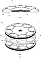
- Fig. 4 is an exploded view of a rotor core with another structure according to the first embodiment of the present invention.
- Fig. 5 is an exploded sectional view of the rotor core with the other structure according to the first embodiment of the present invention.
- Fig. 6 is a sectional view of the rotor core with the other structure according to the first embodiment of the present invention.
- the rotor core 20 has rotor structures 21 in two layers, and the rotor structure 21 in each layer includes the rotor yoke 11 and the multiple magnetic pole core groups 12.
- the rotor structure 21 in each layer is the same as the structure of the rotor core 10 illustrated in Figs. 1 to 3 , and thus duplicated description of the specific structure is eliminated.
- the rotor core 20 further includes a spacing structure 22 provided between the adjacent rotor structures 21 in two layers.
- the spacing structure 22 includes multiple second permanent magnets 221 connecting the magnetic conductors 121 corresponding to the adjacent rotor structures 21 in the two layers.
- Fig. 7 is a plan view of a partial structure of the rotor core according to the first embodiment of the present invention.
- Fig. 8 is a front view of the partial structure of the rotor core according to the first embodiment of the present invention.
- the magnetic conductors 121 corresponding to the adjacent rotor structures 21 in the two layers are identical in dimension in section taken along the axial direction. Then, the second permanent magnet 221 connecting the corresponding two magnetic conductors 121 has two end surfaces in the axial direction that are also identical in dimension.
- Fig. 9 is an exploded view of a rotor core with yet another structure according to the first embodiment of the present invention.
- Fig. 10 is an exploded sectional view of the rotor core with the yet other structure according to the first embodiment of the present invention.
- Fig. 11 is a sectional view of the rotor core with the yet other structure according to the first embodiment of the present invention.
- a rotor core 30 has rotor structures 31 in two layers, and the rotor structure 31 in each layer includes the rotor yoke 11 and the multiple magnetic pole core groups 12.
- the rotor structure 31 in each layer is the same as the structure of the rotor core 10 illustrated in Figs. 1 to 3 , and thus duplicated description of specific structure is eliminated.
- the rotor core 30 further includes a spacing structure 32 provided between the adjacent rotor structures 31 in two layers.
- the spacing structure 32 includes multiple second permanent magnets 321 connecting the magnetic conductors 121 corresponding to the adjacent rotor structures 31 in the two layers.
- Fig. 12 is a plan view of another partial structure of the rotor core according to the first embodiment of the present invention.
- Fig. 13 is a front view of the other partial structure of the rotor core according to the first embodiment of the present invention.
- the magnetic conductors 121 corresponding to the adjacent rotor structures 31 in the two layers are identical in shape in section taken along the axial direction and different in dimension in the section. Then, the second permanent magnets 321 connecting the corresponding two magnetic conductors 121 have two end surfaces in the axial direction that are also different in dimension. Then, a magnetic flux can be better guided to move toward the stator.
- each magnetic pole core group includes the magnetic conductor at its center and the multiple permanent magnets around the magnetic conductor
- the structure becomes compact and reliable as a whole, and thus another mechanical structure for maintaining rigidity of the rotor is not required.
- the method for manufacturing the magnetic pole core groups facilitates mass production and manufacturing without causing a cumulative error in manufacturing and assembly.
- the center of each magnetic pole core group is formed of the magnetic conductor, so that the number of magnets to be used can be reduced at the maximum to achieve low cost.
- the multiple permanent magnets provided around the magnetic conductor enables increasing the magnetic flux concentration effect while preventing magnetic flux leakage. Thus, both high efficiency and high performance of the motor can be achieved.
- a second embodiment of the present invention further provides a rotor core.
- Fig. 14 is a plan view of a rotor core according to the second embodiment of the present invention.
- Fig. 15 is a bottom view of the rotor core according to the second embodiment of the present invention.
- a rotor core 40 includes a rotor yoke 41 formed by stacking multiple silicon steel sheets in an axial direction of the rotor yoke, and multiple magnetic pole core groups 42 accommodated in respective accommodation holes 411 provided in the rotor yoke 41 in a circumferential direction of the rotor yoke.
- the magnetic pole core groups 42 each include a third permanent magnet 421 provided at a center of each magnetic pole core group and multiple fourth permanent magnets 422 provided around a periphery of the third permanent magnet 421.
- the third permanent magnet 421 has a magnetic pole direction that points to one side in the axial direction and the multiple fourth permanent magnets 422 each have a magnetic pole direction that points radially inward or radially outward of each of the magnetic pole core groups 42.
- each magnetic pole core group 42 includes the permanent magnet 421 at its center and the multiple permanent magnets 422 around this permanent magnet, the structure becomes compact and reliable as a whole, and thus another mechanical structure for maintaining rigidity of the rotor is not required.
- the method for manufacturing the magnetic pole core groups 42 facilitates mass production and manufacturing without causing a cumulative error in manufacturing and assembly. Both the center and the periphery of each magnetic pole core group 42 are formed of the permanent magnets, so that the magnetic flux concentration effect can be increased while magnetic flux leakage is prevented. Thus, high efficiency and high performance of the motor can be ensured to the maximum.
- the present embodiment provides the rotor yoke 41 that is formed by stacking multiple silicon steel sheets in the axial direction.
- the rotor yoke 41 is provided with the multiple accommodation holes 411 in the circumferential direction, the accommodation holes 411 passing through the rotor yoke 41 in the axial direction. Then, one magnetic pole core group 42 is provided for each accommodation hole 411.
- the number of the accommodation holes 411 and the magnetic pole core groups 42, and positions of the accommodation holes 411 and the magnetic pole core groups 42 in the circumferential direction and the radial direction, may be set according to actual needs.
- the multiple magnetic pole core groups 42 each include the multiple fourth permanent magnets 422 close to a center hole 412 of the rotor yoke, the multiple fourth permanent magnets 422 being provided around the center hole 412, as illustrated Figs. 14 and 15 .
- two adjacent magnetic pole core groups 42 include the respective multiple fourth permanent magnets 422 that are opposite to each other in magnetic pole direction.
- the fourth permanent magnets 422 in one magnetic pole core group of the two adjacent magnetic pole core groups have a magnetic pole direction pointing radially inward of the one magnetic pole core group
- the fourth permanent magnets 422 in the other magnetic pole core group have a magnetic pole direction pointing radially outward of the other magnetic pole core group.
- the multiple magnetic pole core groups include two adjacent magnetic pole core groups including the respective third permanent magnets that are opposite to each other in magnetic pole direction.
- each magnetic pole core group 42 is identical in structure, so that the specific structure of one of the magnetic pole core groups 42 will be described below.
- the third permanent magnet 421 has a polygonal section taken along the axial direction, and a specific shape of the polygon may be set depending on actual needs.
- the third permanent magnet 421 has a pentagonal section taken along the axial direction as illustrated in Figs. 14 and 15 .
- the fourth permanent magnets 422 are each a rectangular parallelepiped or a wedge-shaped cube, and the first permanent magnet 122 has a length equal to a dimension of each side of the magnetic conductor 122.
- the fourth permanent magnet 422 is a wedge-shaped cube, no gap may be formed between two adjacent fourth permanent magnets 422. Then, magnetic flux leakage can be further prevented from occurring.
- the third permanent magnet 421 is larger in dimension in the axial direction than each of the fourth permanent magnets 422.
- the third permanent magnet 421 has a surface facing the stator in the axial direction, the surface protruding from an end surface of the rotor yoke 41, the end surface facing the stator, and then the fourth permanent magnets 422 are flush with the end surface of the rotor yoke 41 facing the stator.
- each of the fourth permanent magnets 422 may have an end surface recessed to a side opposite to the stator from the end surface of the rotor yoke 41.
- each magnetic pole core group includes the permanent magnet at its center and the multiple permanent magnets around this permanent magnet
- the structure becomes compact and reliable as a whole, and thus another mechanical structure for maintaining rigidity of the rotor is not required.
- the method for manufacturing the magnetic pole core groups facilitates mass production and manufacturing without causing a cumulative error in manufacturing and assembly. Both the center and the periphery of each magnetic pole core group are formed of the permanent magnets, so that the magnetic flux concentration effect can be increased while magnetic flux leakage is prevented. Thus, high efficiency and high performance of the motor can be ensured to the maximum.
- a third embodiment of the present invention provides a motor including the rotor core described in the first or second embodiment.
- the first and second embodiments have already described the specific structure of the rotor core, and thus the contents of the specific structure may be adapted here. Hereinafter, the description will be eliminated.
- the motor may be an axial flux motor.
- Fig. 16 is a sectional view of a motor according to the third embodiment of the present invention.
- a motor 100 includes two rotor cores 200 aligned in the axial direction, a stator 300 provided between the two rotor cores 200 in the axial direction, an upper cover 400, a lower cover 500, a bearing 600, a center shaft 700, and a connection structure 800.
- the stator 300 includes a stator inner ring 310, a stator outer ring 320, and a stator sealing resin 330, the stator sealing resin 330 containing a coil and a core.
- the rotor cores 200 each may include the structure of the rotor core described in any one of the first and second embodiments.
- Specific structures of the stator 300, the upper cover 400, the lower cover 500, the bearing 600, the center shaft 700, and the connection structure 800, may refer to the related art.
Landscapes
- Engineering & Computer Science (AREA)
- Power Engineering (AREA)
- Permanent Field Magnets Of Synchronous Machinery (AREA)
- Iron Core Of Rotating Electric Machines (AREA)
Abstract
Description
- The present application relates to the electric and mechanical field, and particularly relates to a rotor core and a motor including the rotor core.
- Axial flux motors are different from general motors. The axial flux motors each have an axial direction as a magnetic flux direction, and a stator and a rotor core that are formed in a disk type. The axial flux motors have advantages such as compact structure, small volume, light weight, and high torque density.
- Typical radial flux type motors are often designed such that a magnet is incorporated to achieve the effect of both high performance and high efficiency while the number of magnets to be used is reduced in response to a demand for large power or large dimensions. Unfortunately, the axial flux motors are rarely designed to incorporate a magnet due to a difference in a magnetic flux direction from general radial flux motors and a limitation by a manufacturing method.
- Although some axial flux motors designed to incorporate magnets currently appear, the magnets are typically disposed in a circumferential direction in these designed motors.
- It should be noted that the above introduction to the technical background merely serves to facilitate the understanding of those skilled in the art while helping to provide a clearer and more complete description of the technical idea of the present invention. The foregoing technical manners described in the technical background section of the present application should not be simply considered to be publicly known to those skilled in the art.
- Unfortunately, these conventional designs have one or more of problems as follows: a rotor has a complicated structure; another mechanical structure for maintaining rigidity of the rotor is required; magnets need to be gathered one by one in a manufacturing process; a cumulative error is likely to occur, and thus a complete rotor cannot be formed; and the axial flux motor has a three-dimensional (3D) structure, and thus a phenomenon of magnetic flux leakage still occurs around magnetic pole surfaces of the magnets.
- To solve at least one of the above problems, the present invention provides a rotor core and a motor including the rotor core. When a rotor yoke is provided with multiple magnetic pole core groups in a circumferential direction and each magnetic pole core group includes a magnetic conductor at its center and multiple permanent magnets around the magnetic conductor, the structure becomes compact and reliable as a whole, and thus another mechanical structure for maintaining rigidity of the rotor is not required. A method for manufacturing the magnetic pole core groups facilitates mass production and manufacturing without causing a cumulative error in manufacturing and assembly. The center of each magnetic pole core group is formed of the magnetic conductor, so that the number of magnets to be used can be reduced at the maximum to achieve low cost. Then, the multiple permanent magnets provided around the magnetic conductor enable increasing the magnetic flux concentration effect while preventing magnetic flux leakage. Thus, both high efficiency and high performance of the motor can be achieved.
- To solve at least one of the above problems, the present invention further provides a rotor core and a motor including the rotor core, in which a rotor yoke is provided with multiple magnetic pole core groups in a circumferential direction and each magnetic pole core group includes a permanent magnet at its center and multiple permanent magnets around this permanent magnet, so that the structure becomes compact and reliable as a whole, and thus another mechanical structure for maintaining rigidity of the rotor is not required. The method for manufacturing the magnetic pole core groups facilitates mass production and manufacturing without causing a cumulative error in manufacturing and assembly. Both the center and the periphery of each magnetic pole core group are formed of the permanent magnets, so that the magnetic flux concentration effect can be increased while magnetic flux leakage is prevented. Thus, high efficiency and high performance of the motor can be ensured to the maximum.
- A first aspect of embodiments of the present invention provides a rotor core including: a rotor yoke formed by stacking multiple silicon steel sheets in an axial direction of the rotor yoke; and multiple magnetic pole core groups accommodated in respective accommodation holes provided in the rotor yoke in a circumferential direction of the rotor yoke. The magnetic pole core groups each include a magnetic conductor provided at a center of each magnetic pole core group and multiple first permanent magnets provided around a periphery of the magnetic conductor. The multiple first permanent magnets each have a magnetic pole direction that points radially inward or radially outward of each of the magnetic pole core groups.
- According to a second aspect of the embodiments of the present invention, the multiple magnetic pole core groups include two adjacent magnetic pole core groups including the respective multiple first permanent magnets that are opposite to each other in the magnetic pole direction.
- According to a third aspect of the embodiments of the present invention, the magnetic conductor has a polygonal section taken along the axial direction, and the first permanent magnets are each a rectangular parallelepiped.
- According to a fourth aspect of the embodiments of the present invention, the magnetic conductor is larger in dimension in the axial direction than each of the first permanent magnets.
- According to a fifth aspect of the embodiments of the present invention, the magnetic conductor protrudes from an end surface of the rotor yoke, the end surface being close to a stator in the axial direction.
- According to a sixth aspect of the embodiments of the present invention, the rotor core has rotor structures in at least two layers. Each of the rotor structures of the layers includes the rotor yoke and the multiple magnetic pole core groups. The rotor core further has a spacing structure provided between adjacent rotor structures in two layers, and the spacing structure includes multiple second permanent magnets connecting magnetic conductors corresponding to the adjacent rotor structures in the two layers.
- According to a seventh aspect of the embodiments of the present invention, the magnetic conductors corresponding to the adjacent rotor structures in two layers are identical or different in dimension in section taken along the axial direction.
- According to an eighth aspect of the embodiments of the present invention, the magnetic conductors corresponding to the adjacent rotor structures in two layers are different in dimension in section taken along the axial direction, and each of the second permanent magnets connecting the corresponding two magnetic conductors has two end surfaces in the axial direction, the two end surfaces being different in dimension.
- A ninth aspect of the embodiments of the present invention provides a rotor core including: a rotor yoke formed by stacking multiple silicon steel sheets in an axial direction of the rotor yoke; and multiple magnetic pole core groups accommodated in respective accommodation holes provided in the rotor yoke in a circumferential direction of the rotor yoke. The magnetic pole core groups each include a third permanent magnet provided at a center of each magnetic pole core group, and multiple fourth permanent magnets provided around a periphery of the third permanent magnet. The third permanent magnet has a magnetic pole direction that points to one side in the axial direction, and the multiple fourth permanent magnets each have a magnetic pole direction that points radially inward or radially outward of each of the magnetic pole core groups.
- According to a tenth aspect of the embodiments of the present invention, the multiple magnetic pole core groups include two adjacent magnetic pole core groups including the multiple fourth permanent magnets that are opposite to each other in magnetic pole direction, and the multiple magnetic pole core groups include two adjacent magnetic pole core groups including the respective third permanent magnets that are opposite to each other in magnetic pole direction.
- According to an eleventh aspect of the embodiments of the present invention, the third permanent magnet has a polygonal section taken along the axial direction, and the fourth permanent magnets are each a rectangular parallelepiped or a wedge-shaped cube.
- According to a twelfth aspect of the embodiments of the present invention, the third permanent magnet is larger in dimension in the axial direction than each of the fourth permanent magnets.
- According to a thirteenth aspect of the embodiments of the present invention, the third permanent magnet protrudes from an end surface of the rotor yoke, the end surface being close to the stator in the axial direction.
- According to a fourteenth aspect of the embodiments of the present invention, the multiple magnetic pole core groups each include the multiple fourth permanent magnets close to a center hole of the rotor yoke, the multiple fourth permanent magnets being provided around the center hole.
- A fifteenth aspect of the embodiments of the present invention provides a motor including the rotor core according to any one of the first to fourteenth aspects of the embodiments of the present invention.
- Advantageous effects according to the embodiments of the present invention are as follows. When a rotor yoke is provided with multiple magnetic pole core groups in a circumferential direction and each magnetic pole core group includes a magnetic conductor at its center and multiple permanent magnets around the magnetic conductor, the structure becomes compact and reliable as a whole, and thus another mechanical structure for maintaining rigidity of the rotor is not required. The method for manufacturing the magnetic pole core groups facilitates mass production and manufacturing without causing a cumulative error in manufacturing and assembly. The center of each magnetic pole core group is formed of the magnetic conductor, so that the number of magnets to be used can be reduced at the maximum to achieve low cost. Then, the multiple permanent magnets provided around the magnetic conductor enables increasing the magnetic flux concentration effect while preventing magnetic flux leakage. Thus, both high efficiency and high performance of the motor can be achieved.
- Alternatively, when the rotor yoke is provided with the multiple magnetic pole core groups in the circumferential direction and each magnetic pole core group includes the permanent magnet at its center and the multiple permanent magnets around this permanent magnet, the structure becomes compact and reliable as a whole, and thus another mechanical structure for maintaining rigidity of the rotor is not required. The method for manufacturing the magnetic pole core groups facilitates mass production and manufacturing without causing a cumulative error in manufacturing and assembly. Both the center and the periphery of each magnetic pole core group are formed of the permanent magnets, so that the magnetic flux concentration effect can be increased while magnetic flux leakage is prevented. Thus, high efficiency and high performance of the motor can be ensured to the maximum.
- Embodiments of the present invention are disclosed in detail with reference to the following description and the accompanying drawings. It should be understood that the embodiments of the present invention are not limited in scope by the disclosure. Within the spirit and scope of the appended claims, the embodiments of the present invention include many changes, modifications, and equivalents.
- Descriptions of one embodiment and/or features exhibited can be used for one or more other embodiments in an identical or similar manner, and can be combined with features of the other embodiments or switched with the features of the other embodiments.
- It should be emphasized that although the terms, "including/containing/comprising" is used in the present text to indicate the presence of a feature, a body shaping member, or a part, presence or addition of one or more other features, body shaping members, or parts is not precluded.
- The detailed description below in association with the accompanying drawings will clarify the foregoing and other objects, features, and advantages in the embodiments of the present invention. The accompanying drawings are as follows.
-
-
Fig. 1 is a plan view of a rotor core according to a first embodiment of the present invention. -
Fig. 2 is a bottom view of the rotor core according to the first embodiment of the present invention. -
Fig. 3 is a sectional view of the rotor core according to the first embodiment of the present invention. -
Fig. 4 is an exploded view of a rotor core with another structure according to the first embodiment of the present invention. -
Fig. 5 is an exploded sectional view of the rotor core with the other structure according to the first embodiment of the present invention. -
Fig. 6 is a sectional view of the rotor core with the other structure according to the first embodiment of the present invention. -
Fig. 7 is a plan view of partial structure of the rotor core according to the first embodiment of the present invention. -
Fig. 8 is a front view of the partial structure of the rotor core according to the first embodiment of the present invention. -
Fig. 9 is an exploded view of a rotor core with yet another structure according to the first embodiment of the present invention. -
Fig. 10 is an exploded sectional view of the rotor core with the yet other structure according to the first embodiment of the present invention. -
Fig. 11 is a sectional view of the rotor core with the yet other structure according to the first embodiment of the present invention. -
Fig. 12 is a plan view of another partial structure of the rotor core according to the first embodiment of the present invention. -
Fig. 13 is a front view of the other partial structure of the rotor core according to the first embodiment of the present invention. -
Fig. 14 is a plan view of a rotor core according to a second embodiment of the present invention. -
Fig. 15 is a bottom view of the rotor core according to the second embodiment of the present invention. -
Fig. 16 is a sectional view of a motor according to a third embodiment of the present invention. - With reference to the drawings, the following description will clarify the foregoing and other features of the present invention. It should be noted that although the specification and drawings specifically disclose specific embodiments of the present invention and show some of the embodiments in which the principle of the present invention is applicable, the present invention is not limited to the described embodiments, and includes all modifications, variations, and equivalents falling within the scope of the claims appended.
- In the present invention, a direction parallel to a direction extending along a center axis is referred to as an "axial direction", a radial direction centered on the center axis is referred to as a "radial direction", and a circumferential direction around the center axis is referred to as a "circumferential direction". It should be noted that the directions are defined in the present invention for convenience of description of the embodiments of the present invention, and thus do not limit directions at the time of use or manufacture of the rotor and the motor.
- Hereinafter, a rotor core and a motor according to an embodiment of the present invention will be described with reference to the accompanying drawings.
- A first embodiment of the present invention provides a rotor core.
-
Fig. 1 is a plan view of the rotor core according to the first embodiment of the present invention.Fig. 2 is a bottom view of the rotor core according to the first embodiment of the present invention.Fig. 3 is a sectional view of the rotor core according to the first embodiment of the present invention. - As illustrated in
Figs. 1, 2 , and3 , arotor core 10 includes arotor yoke 11 formed by stacking multiple silicon steel sheets in an axial direction of therotor yoke 11; and multiple magneticpole core groups 12 accommodated inrespective accommodation holes 111 provided in therotor yoke 11 in a circumferential direction of therotor yoke 11. The magneticpole core groups 12 each include amagnetic conductor 121 provided at a center of each magnetic pole core group and multiple firstpermanent magnets 122 provided around a periphery of themagnetic conductor 121. The multiple firstpermanent magnets 122 each have a magnetic pole direction that points radially inward or radially outward of each of the magnetic pole core groups 12. - Then, when the
rotor yoke 11 is provided with the multiple magneticpole core groups 12 in the circumferential direction and each magneticpole core group 12 includes themagnetic conductor 121 at its center and the multiplepermanent magnets 122 around the magnetic conductor, the structure becomes compact and reliable as a whole, and thus another mechanical structure for maintaining rigidity of the rotor is not required. The method for manufacturing the magneticpole core groups 12 facilitates mass production and manufacturing without causing a cumulative error in manufacturing and assembly. The center of each magnetic pole core group is formed of the magnetic conductor, so that the number of magnets to be used can be reduced at the maximum to achieve low cost. Then, the multiple permanent magnets provided around the magnetic conductor enables increasing the magnetic flux concentration effect while preventing magnetic flux leakage. Thus, both high efficiency and high performance of the motor can be achieved. - As illustrated in
Figs. 1, 2 , and3 , the present embodiment provides therotor yoke 11 that is formed by stacking multiple silicon steel sheets in the axial direction. Therotor yoke 11 is provided with themultiple accommodation holes 111 in the circumferential direction, the accommodation holes 111 passing through therotor yoke 11 in the axial direction. Then, one magneticpole core group 12 is provided for eachaccommodation hole 111. - According to the present embodiment, the number of the accommodation holes 111 and the magnetic
pole core groups 12, and positions of the accommodation holes 111 and the magneticpole core groups 12 in the circumferential direction and the radial direction, may be set according to actual needs. - According to the present embodiment, two adjacent magnetic
pole core groups 12 include the respective multiple firstpermanent magnets 122 that are opposite to each other in magnetic pole direction. For example, when the firstpermanent magnets 122 in one magnetic pole core group of the two adjacent magnetic pole core groups have a magnetic pole direction pointing radially inward of the one magnetic pole core group, the firstpermanent magnets 122 in the other magnetic pole core group have a magnetic pole direction pointing radially outward of the other magnetic pole core group. - According to the present embodiment, each magnetic
pole core group 12 is identical in structure, so that the specific structure of one of the magneticpole core groups 12 will be described below. - According to the present embodiment, the
magnetic conductor 121 has a polygonal section taken along the axial direction, and a specific shape of the polygon may be set depending on actual needs. - For example, the
magnetic conductor 121 has a hexagonal section taken along the axial direction as illustrated inFigs. 1 and 2 . - According to the present embodiment, the first
permanent magnets 122 are each a rectangular parallelepiped, and the firstpermanent magnets 122 each have a length equal to a dimension of each side of themagnetic conductor 121 as illustrated inFigs. 1 and3 . - This structure facilitates manufacturing of the
magnetic conductor 121 and the firstpermanent magnets 122. - As illustrated in
Fig. 3 , themagnetic conductor 121 is larger in dimension in the axial direction than each of the firstpermanent magnets 122. For example, themagnetic conductor 121 has a surface facing the stator in the axial direction, the surface protruding from an end surface of therotor yoke 11, the end surface facing the stator, and then the firstpermanent magnets 122 are flush with the end surface of therotor yoke 11 facing the stator. Alternatively, each of the firstpermanent magnets 122 may have an end surface recessed to a side opposite to the stator from the end surface of therotor yoke 11. - Then, a magnetic flux can be better guided to move toward the stator.
- According to the present embodiment, the rotor core has the rotor structures in at least two layers, and the rotor structure in each layer may have the rotor yoke and the multiple magnetic pole core groups. For example, the rotor structure in each layer may have the structure illustrated in
Figs. 1 to 3 . - Then, providing the multilayer structure enables the motor to be further improved in efficiency and performance.
- The present embodiment describes the rotor core having the rotor structure of two layers as an example.
-
Fig. 4 is an exploded view of a rotor core with another structure according to the first embodiment of the present invention.Fig. 5 is an exploded sectional view of the rotor core with the other structure according to the first embodiment of the present invention.Fig. 6 is a sectional view of the rotor core with the other structure according to the first embodiment of the present invention. - As illustrated in
Figs. 4 ,5 , and6 , therotor core 20 hasrotor structures 21 in two layers, and therotor structure 21 in each layer includes therotor yoke 11 and the multiple magnetic pole core groups 12. Therotor structure 21 in each layer is the same as the structure of therotor core 10 illustrated inFigs. 1 to 3 , and thus duplicated description of the specific structure is eliminated. - The
rotor core 20 further includes aspacing structure 22 provided between theadjacent rotor structures 21 in two layers. Thespacing structure 22 includes multiple secondpermanent magnets 221 connecting themagnetic conductors 121 corresponding to theadjacent rotor structures 21 in the two layers. -
Fig. 7 is a plan view of a partial structure of the rotor core according to the first embodiment of the present invention.Fig. 8 is a front view of the partial structure of the rotor core according to the first embodiment of the present invention. - As illustrated in
Figs. 7 and8 , themagnetic conductors 121 corresponding to theadjacent rotor structures 21 in the two layers are identical in dimension in section taken along the axial direction. Then, the secondpermanent magnet 221 connecting the corresponding twomagnetic conductors 121 has two end surfaces in the axial direction that are also identical in dimension. -
Fig. 9 is an exploded view of a rotor core with yet another structure according to the first embodiment of the present invention.Fig. 10 is an exploded sectional view of the rotor core with the yet other structure according to the first embodiment of the present invention.Fig. 11 is a sectional view of the rotor core with the yet other structure according to the first embodiment of the present invention. - As illustrated in
Figs. 9 ,10 , and11 , arotor core 30 hasrotor structures 31 in two layers, and therotor structure 31 in each layer includes therotor yoke 11 and the multiple magnetic pole core groups 12. Therotor structure 31 in each layer is the same as the structure of therotor core 10 illustrated inFigs. 1 to 3 , and thus duplicated description of specific structure is eliminated. - The
rotor core 30 further includes aspacing structure 32 provided between theadjacent rotor structures 31 in two layers. Thespacing structure 32 includes multiple secondpermanent magnets 321 connecting themagnetic conductors 121 corresponding to theadjacent rotor structures 31 in the two layers. -
Fig. 12 is a plan view of another partial structure of the rotor core according to the first embodiment of the present invention.Fig. 13 is a front view of the other partial structure of the rotor core according to the first embodiment of the present invention. - As illustrated in
Figs. 12 and13 , themagnetic conductors 121 corresponding to theadjacent rotor structures 31 in the two layers are identical in shape in section taken along the axial direction and different in dimension in the section. Then, the secondpermanent magnets 321 connecting the corresponding twomagnetic conductors 121 have two end surfaces in the axial direction that are also different in dimension. Then, a magnetic flux can be better guided to move toward the stator. - As can be seen from the above embodiment, when the rotor yoke is provided with the multiple magnetic pole core groups in the circumferential direction and each magnetic pole core group includes the magnetic conductor at its center and the multiple permanent magnets around the magnetic conductor, the structure becomes compact and reliable as a whole, and thus another mechanical structure for maintaining rigidity of the rotor is not required. The method for manufacturing the magnetic pole core groups facilitates mass production and manufacturing without causing a cumulative error in manufacturing and assembly. The center of each magnetic pole core group is formed of the magnetic conductor, so that the number of magnets to be used can be reduced at the maximum to achieve low cost. Then, the multiple permanent magnets provided around the magnetic conductor enables increasing the magnetic flux concentration effect while preventing magnetic flux leakage. Thus, both high efficiency and high performance of the motor can be achieved.
- A second embodiment of the present invention further provides a rotor core.
-
Fig. 14 is a plan view of a rotor core according to the second embodiment of the present invention.Fig. 15 is a bottom view of the rotor core according to the second embodiment of the present invention. - As illustrated in
Figs. 14 and15 , arotor core 40 includes arotor yoke 41 formed by stacking multiple silicon steel sheets in an axial direction of the rotor yoke, and multiple magneticpole core groups 42 accommodated inrespective accommodation holes 411 provided in therotor yoke 41 in a circumferential direction of the rotor yoke. The magneticpole core groups 42 each include a thirdpermanent magnet 421 provided at a center of each magnetic pole core group and multiple fourthpermanent magnets 422 provided around a periphery of the thirdpermanent magnet 421. The thirdpermanent magnet 421 has a magnetic pole direction that points to one side in the axial direction and the multiple fourthpermanent magnets 422 each have a magnetic pole direction that points radially inward or radially outward of each of the magnetic pole core groups 42. - Then, when the
rotor yoke 41 is provided with the multiple magneticpole core groups 42 in the circumferential direction and each magneticpole core group 42 includes thepermanent magnet 421 at its center and the multiplepermanent magnets 422 around this permanent magnet, the structure becomes compact and reliable as a whole, and thus another mechanical structure for maintaining rigidity of the rotor is not required. The method for manufacturing the magneticpole core groups 42 facilitates mass production and manufacturing without causing a cumulative error in manufacturing and assembly. Both the center and the periphery of each magneticpole core group 42 are formed of the permanent magnets, so that the magnetic flux concentration effect can be increased while magnetic flux leakage is prevented. Thus, high efficiency and high performance of the motor can be ensured to the maximum. - As illustrated in
Figs. 14 and15 , the present embodiment provides therotor yoke 41 that is formed by stacking multiple silicon steel sheets in the axial direction. Therotor yoke 41 is provided with themultiple accommodation holes 411 in the circumferential direction, the accommodation holes 411 passing through therotor yoke 41 in the axial direction. Then, one magneticpole core group 42 is provided for eachaccommodation hole 411. - According to the present embodiment, the number of the accommodation holes 411 and the magnetic
pole core groups 42, and positions of the accommodation holes 411 and the magneticpole core groups 42 in the circumferential direction and the radial direction, may be set according to actual needs. - For example, the multiple magnetic
pole core groups 42 each include the multiple fourthpermanent magnets 422 close to a center hole 412 of the rotor yoke, the multiple fourthpermanent magnets 422 being provided around the center hole 412, as illustratedFigs. 14 and15 . - According to the present embodiment, two adjacent magnetic
pole core groups 42 include the respective multiple fourthpermanent magnets 422 that are opposite to each other in magnetic pole direction. For example, when the fourthpermanent magnets 422 in one magnetic pole core group of the two adjacent magnetic pole core groups have a magnetic pole direction pointing radially inward of the one magnetic pole core group, the fourthpermanent magnets 422 in the other magnetic pole core group have a magnetic pole direction pointing radially outward of the other magnetic pole core group. The multiple magnetic pole core groups include two adjacent magnetic pole core groups including the respective third permanent magnets that are opposite to each other in magnetic pole direction. - According to the present embodiment, each magnetic
pole core group 42 is identical in structure, so that the specific structure of one of the magneticpole core groups 42 will be described below. - According to the present embodiment, the third
permanent magnet 421 has a polygonal section taken along the axial direction, and a specific shape of the polygon may be set depending on actual needs. - For example, the third
permanent magnet 421 has a pentagonal section taken along the axial direction as illustrated inFigs. 14 and15 . - According to the present embodiment, the fourth
permanent magnets 422 are each a rectangular parallelepiped or a wedge-shaped cube, and the firstpermanent magnet 122 has a length equal to a dimension of each side of themagnetic conductor 122. When the fourthpermanent magnet 422 is a wedge-shaped cube, no gap may be formed between two adjacent fourthpermanent magnets 422. Then, magnetic flux leakage can be further prevented from occurring. - According to the present embodiment, the third
permanent magnet 421 is larger in dimension in the axial direction than each of the fourthpermanent magnets 422. For example, the thirdpermanent magnet 421 has a surface facing the stator in the axial direction, the surface protruding from an end surface of therotor yoke 41, the end surface facing the stator, and then the fourthpermanent magnets 422 are flush with the end surface of therotor yoke 41 facing the stator. Alternatively, each of the fourthpermanent magnets 422 may have an end surface recessed to a side opposite to the stator from the end surface of therotor yoke 41. - Then, a magnetic flux can be better guided to move toward the stator.
- As can be seen from the above embodiment, when the rotor yoke is provided with the multiple magnetic pole core groups in the circumferential direction and each magnetic pole core group includes the permanent magnet at its center and the multiple permanent magnets around this permanent magnet, the structure becomes compact and reliable as a whole, and thus another mechanical structure for maintaining rigidity of the rotor is not required. The method for manufacturing the magnetic pole core groups facilitates mass production and manufacturing without causing a cumulative error in manufacturing and assembly. Both the center and the periphery of each magnetic pole core group are formed of the permanent magnets, so that the magnetic flux concentration effect can be increased while magnetic flux leakage is prevented. Thus, high efficiency and high performance of the motor can be ensured to the maximum.
- A third embodiment of the present invention provides a motor including the rotor core described in the first or second embodiment. The first and second embodiments have already described the specific structure of the rotor core, and thus the contents of the specific structure may be adapted here. Hereinafter, the description will be eliminated.
- According to the present embodiment, the motor may be an axial flux motor.
-
Fig. 16 is a sectional view of a motor according to the third embodiment of the present invention. As illustrated inFig. 16 , amotor 100 includes tworotor cores 200 aligned in the axial direction, astator 300 provided between the tworotor cores 200 in the axial direction, anupper cover 400, alower cover 500, abearing 600, acenter shaft 700, and aconnection structure 800. - The
stator 300 includes a statorinner ring 310, a statorouter ring 320, and astator sealing resin 330, thestator sealing resin 330 containing a coil and a core. - According to the present embodiment, the
rotor cores 200 each may include the structure of the rotor core described in any one of the first and second embodiments. Specific structures of thestator 300, theupper cover 400, thelower cover 500, thebearing 600, thecenter shaft 700, and theconnection structure 800, may refer to the related art. - The foregoing has described the embodiments of the present invention in detail with reference to the accompanying drawings, and has also specified a manner in which the principles of the present invention can be used. However, it should be understood that the implementation of the present invention is not limited to the manner in the above embodiments, and further includes all modifications, corrections, equivalents, and the like within a range without departing from the gist of the present invention.
Claims (15)
- A rotor core (10, 20, 30) comprising:a rotor yoke (11) formed by stacking multiple silicon steel sheets in an axial direction of the rotor yoke (11); andmultiple magnetic pole core groups (12) accommodated in respective accommodation holes (111) provided in the rotor yoke (11) in a circumferential direction of the rotor yoke (11),the magnetic pole core groups (12) each including:a magnetic conductor (121) provided at a center of each magnetic pole core group (12); andmultiple first permanent magnets (122) provided around a periphery of the magnetic conductor (121), andthe multiple first permanent magnets (122) each having a magnetic pole direction that points radially inward or radially outward of each of the magnetic pole core groups (12).
- The rotor core (10, 20, 30) according to claim 1, characterized in that the multiple magnetic pole core groups (12) include two adjacent magnetic pole core groups (12) including the multiple first permanent magnets (122) that are opposite to each other in the magnetic pole direction.
- The rotor core (10, 20, 30) according to claim 1, characterized in that the magnetic conductor (121) has a polygonal section taken along the axial direction, and the first permanent magnets (122) are each a rectangular parallelepiped.
- The rotor core (10, 20, 30) according to claim 1, characterized in that the magnetic conductor (121) is larger in dimension in the axial direction than each of the first permanent magnets (122).
- The rotor core (10, 20, 30) according to claim 1 or 4, characterized in that the magnetic conductor (121) protrudes from an end surface of the rotor yoke (11), the end surface being close to a stator (300) in the axial direction.
- The rotor core (10, 20, 30) according to claim 1, characterized in thatthe rotor core (10, 20, 30) has rotor structures (21, 31) in at least two layers,each of the rotor structures (21, 31) of the layers includes the rotor yoke (11) and the multiple magnetic pole core groups (12),the rotor core (10, 20, 30) further has a spacing structure (22, 32) provided between adjacent rotor structures (21, 31) in two layers, andthe spacing structure (22, 32) includes multiple second permanent magnets (221, 321) connecting the magnetic conductors (121) corresponding to the adjacent rotor structures (21, 31) in the two layers.
- The rotor core (10, 20, 30) according to claim 6, characterized in that the magnetic conductors (121) corresponding to the adjacent rotor structures (21, 31) in two layers are identical or different in dimension in section taken along the axial direction.
- The rotor core (10, 20, 30) according to claim 7, characterized in thatthe magnetic conductors (121) corresponding to the adjacent rotor structures (21, 31) in two layers are different in dimension in section taken along the axial direction, andeach of the second permanent magnets (221, 321) connecting the corresponding two magnetic conductors (121) has two end surfaces in the axial direction, the two end surfaces being different in dimension.
- A rotor core (40) comprising:a rotor yoke (41) formed by stacking multiple silicon steel sheets in an axial direction of the rotor yoke (41); andmultiple magnetic pole core groups (42) accommodated in respective accommodation holes (411) provided in the rotor yoke (41) in a circumferential direction of the rotor yoke (41),the magnetic pole core groups (42) each including:a third permanent magnet (421) provided at a center of each magnetic pole core group (42); andmultiple fourth permanent magnets (422) provided around a periphery of the third permanent magnet (421),the third permanent magnet (421) having a magnetic pole direction that points to one side in the axial direction, andthe multiple fourth permanent magnets (422) each having a magnetic pole direction that points radially inward or radially outward of each of the magnetic pole core groups (42).
- The rotor core (40) according to claim 9, characterized in thatthe multiple magnetic pole core groups (42) include two adjacent magnetic pole core groups (42) including the multiple fourth permanent magnets (422) that are opposite to each other in the magnetic pole direction, andthe multiple magnetic pole core groups (42) include two adjacent magnetic pole core groups (42) including the respective third permanent magnets (421) that are opposite to each other in the magnetic pole direction.
- The rotor core (40) according to claim 9, characterized in thatthe third permanent magnet (421) has a polygonal section taken along the axial direction, andthe fourth permanent magnets (422) are each a rectangular parallelepiped or a wedge-shaped cube.
- The rotor core (40) according to claim 9, characterized in that the third permanent magnet (421) is larger in dimension in the axial direction than each of the fourth permanent magnets (422).
- The rotor core (40) according to claim 9 or 12, characterized in that the third permanent magnet (421) protrudes from an end surface of the rotor yoke (41), the end surface being close to the stator in the axial direction.
- The rotor core (40) according to claim 9, characterized in that the multiple magnetic pole core groups (42) each include the multiple fourth permanent magnets (422) close to a center hole of the rotor yoke (41), the multiple fourth permanent magnets (422) being provided around the center hole.
- A motor (100) comprising the rotor core (10, 20, 30, 40) according to any one of claims 1 to 14.
Applications Claiming Priority (2)
| Application Number | Priority Date | Filing Date | Title |
|---|---|---|---|
| CN201911408814.8A CN113131644A (en) | 2019-12-31 | 2019-12-31 | Rotor core and motor having the same |
| PCT/JP2020/037351 WO2021137275A1 (en) | 2019-12-31 | 2020-09-30 | Rotor core and motor having said rotor core |
Publications (1)
| Publication Number | Publication Date |
|---|---|
| EP4087093A1 true EP4087093A1 (en) | 2022-11-09 |
Family
ID=76687414
Family Applications (1)
| Application Number | Title | Priority Date | Filing Date |
|---|---|---|---|
| EP20909846.6A Withdrawn EP4087093A1 (en) | 2019-12-31 | 2020-09-30 | Rotor core and motor having said rotor core |
Country Status (5)
| Country | Link |
|---|---|
| US (1) | US20230006490A1 (en) |
| EP (1) | EP4087093A1 (en) |
| JP (1) | JP7480712B2 (en) |
| CN (1) | CN113131644A (en) |
| WO (1) | WO2021137275A1 (en) |
Cited By (1)
| Publication number | Priority date | Publication date | Assignee | Title |
|---|---|---|---|---|
| FR3163786A1 (en) * | 2024-06-25 | 2025-12-26 | Anod | Axial flux electric machine |
Families Citing this family (2)
| Publication number | Priority date | Publication date | Assignee | Title |
|---|---|---|---|---|
| CN116848756A (en) * | 2021-03-30 | 2023-10-03 | 华为数字能源技术有限公司 | Motor rotors, motors and electric vehicles |
| CN120090372A (en) * | 2023-12-01 | 2025-06-03 | 珠海格力电器股份有限公司 | Rotor structure and motor |
Family Cites Families (15)
| Publication number | Priority date | Publication date | Assignee | Title |
|---|---|---|---|---|
| US7187098B2 (en) * | 2004-03-03 | 2007-03-06 | Kabushikikaisha Equos Research | Axial gap rotating electrical machine |
| JP2006158008A (en) | 2004-11-25 | 2006-06-15 | Asmo Co Ltd | Permanent magnet embedded rotor and dynamo-electric machine |
| JP4692090B2 (en) * | 2005-06-16 | 2011-06-01 | 株式会社富士通ゼネラル | Axial air gap type electric motor |
| JP2007104819A (en) * | 2005-10-05 | 2007-04-19 | Nissan Motor Co Ltd | Rotating electric machine |
| JP4970974B2 (en) * | 2007-02-14 | 2012-07-11 | ダイキン工業株式会社 | Rotating electric machine |
| JP4960749B2 (en) * | 2007-04-17 | 2012-06-27 | 本田技研工業株式会社 | Axial gap type motor |
| JP4961302B2 (en) * | 2007-08-29 | 2012-06-27 | 本田技研工業株式会社 | Axial gap type motor |
| JP2009106051A (en) | 2007-10-23 | 2009-05-14 | Daihatsu Motor Co Ltd | Rotor |
| JP5468215B2 (en) * | 2008-06-09 | 2014-04-09 | ダイキン工業株式会社 | Air conditioner and method of manufacturing air conditioner |
| JP2010161897A (en) | 2009-01-09 | 2010-07-22 | Daikin Ind Ltd | Rotor, rotating electric machine, and closed type compressor |
| JP5046051B2 (en) * | 2009-01-28 | 2012-10-10 | 本田技研工業株式会社 | Axial gap type motor |
| FI122696B (en) * | 2010-03-31 | 2012-05-31 | Kone Corp | Electric motor, elevator machinery and lift system |
| KR20160060387A (en) * | 2014-11-20 | 2016-05-30 | 삼성전자주식회사 | Hollow brushless motor structure |
| JP6835692B2 (en) * | 2017-10-12 | 2021-02-24 | 株式会社神戸製鋼所 | Electric motor |
| CN111355313A (en) * | 2018-12-24 | 2020-06-30 | 日本电产株式会社 | Axial flux motor and electric product |
-
2019
- 2019-12-31 CN CN201911408814.8A patent/CN113131644A/en active Pending
-
2020
- 2020-09-30 JP JP2020571885A patent/JP7480712B2/en active Active
- 2020-09-30 WO PCT/JP2020/037351 patent/WO2021137275A1/en not_active Ceased
- 2020-09-30 EP EP20909846.6A patent/EP4087093A1/en not_active Withdrawn
- 2020-09-30 US US17/778,616 patent/US20230006490A1/en not_active Abandoned
Cited By (1)
| Publication number | Priority date | Publication date | Assignee | Title |
|---|---|---|---|---|
| FR3163786A1 (en) * | 2024-06-25 | 2025-12-26 | Anod | Axial flux electric machine |
Also Published As
| Publication number | Publication date |
|---|---|
| CN113131644A (en) | 2021-07-16 |
| JP7480712B2 (en) | 2024-05-10 |
| JPWO2021137275A1 (en) | 2021-07-08 |
| US20230006490A1 (en) | 2023-01-05 |
| WO2021137275A1 (en) | 2021-07-08 |
Similar Documents
| Publication | Publication Date | Title |
|---|---|---|
| US7528519B2 (en) | Permanent magnet rotary motor | |
| US9088199B2 (en) | Motor | |
| US20230006490A1 (en) | Rotor core and motor including the rotor core | |
| US10141797B2 (en) | Electric motor having a polygon stator | |
| KR102163345B1 (en) | Synchronous reluctance type rotating electric machine | |
| US11025110B2 (en) | Brushless direct current motor and dual clutch transmission thereof | |
| CN107565723A (en) | Rotor | |
| US9543805B2 (en) | Axial bearing device having increased iron filling | |
| US20130207501A1 (en) | Rotary electric machine | |
| WO2021145136A1 (en) | Axial gap motor | |
| US10707708B2 (en) | Rotor core, rotor, and motor including same | |
| CN109983676A (en) | Synchronous reluctance type rotating electric machine | |
| US20210226491A1 (en) | Rotor and motor | |
| US11901773B2 (en) | Rotating electric machine | |
| EP3098942B1 (en) | Rotor | |
| JP6451517B2 (en) | Rotor | |
| US20250062648A1 (en) | Rotor and rotating electrical machine | |
| US20200083766A1 (en) | Rotor and motor using same | |
| WO2023053604A1 (en) | Rotor and rotating electric machine | |
| WO2013111335A1 (en) | Rotary electric machine | |
| EP4300774B1 (en) | Rotating electrical machine | |
| US20250023439A1 (en) | Offset overlap type of modulated ferromagnetic pole piece ring and method thereof | |
| US12494684B2 (en) | Rotor of an electric machine | |
| US20190363595A1 (en) | Rotor and motor using same | |
| US12199484B2 (en) | Slot-less motor |
Legal Events
| Date | Code | Title | Description |
|---|---|---|---|
| STAA | Information on the status of an ep patent application or granted ep patent |
Free format text: STATUS: THE INTERNATIONAL PUBLICATION HAS BEEN MADE |
|
| PUAI | Public reference made under article 153(3) epc to a published international application that has entered the european phase |
Free format text: ORIGINAL CODE: 0009012 |
|
| STAA | Information on the status of an ep patent application or granted ep patent |
Free format text: STATUS: REQUEST FOR EXAMINATION WAS MADE |
|
| 17P | Request for examination filed |
Effective date: 20220728 |
|
| AK | Designated contracting states |
Kind code of ref document: A1 Designated state(s): AL AT BE BG CH CY CZ DE DK EE ES FI FR GB GR HR HU IE IS IT LI LT LU LV MC MK MT NL NO PL PT RO RS SE SI SK SM TR |
|
| DAV | Request for validation of the european patent (deleted) | ||
| DAX | Request for extension of the european patent (deleted) | ||
| STAA | Information on the status of an ep patent application or granted ep patent |
Free format text: STATUS: THE APPLICATION IS DEEMED TO BE WITHDRAWN |
|
| 18D | Application deemed to be withdrawn |
Effective date: 20240403 |