EP4087074A1 - Method and equipment for installing a power cable in a deployment site - Google Patents
Method and equipment for installing a power cable in a deployment site Download PDFInfo
- Publication number
- EP4087074A1 EP4087074A1 EP22167333.8A EP22167333A EP4087074A1 EP 4087074 A1 EP4087074 A1 EP 4087074A1 EP 22167333 A EP22167333 A EP 22167333A EP 4087074 A1 EP4087074 A1 EP 4087074A1
- Authority
- EP
- European Patent Office
- Prior art keywords
- conveyor belt
- holder
- cable span
- rail
- cable
- Prior art date
- Legal status (The legal status is an assumption and is not a legal conclusion. Google has not performed a legal analysis and makes no representation as to the accuracy of the status listed.)
- Granted
Links
Images




Classifications
-
- H—ELECTRICITY
- H02—GENERATION; CONVERSION OR DISTRIBUTION OF ELECTRIC POWER
- H02G—INSTALLATION OF ELECTRIC CABLES OR LINES, OR OF COMBINED OPTICAL AND ELECTRIC CABLES OR LINES
- H02G1/00—Methods or apparatus specially adapted for installing, maintaining, repairing or dismantling electric cables or lines
- H02G1/06—Methods or apparatus specially adapted for installing, maintaining, repairing or dismantling electric cables or lines for laying cables, e.g. laying apparatus on vehicle
- H02G1/08—Methods or apparatus specially adapted for installing, maintaining, repairing or dismantling electric cables or lines for laying cables, e.g. laying apparatus on vehicle through tubing or conduit, e.g. rod or draw wire for pushing or pulling
- H02G1/081—Methods or apparatus specially adapted for installing, maintaining, repairing or dismantling electric cables or lines for laying cables, e.g. laying apparatus on vehicle through tubing or conduit, e.g. rod or draw wire for pushing or pulling using pulling means at cable ends, e.g. pulling eyes or anchors
-
- B—PERFORMING OPERATIONS; TRANSPORTING
- B65—CONVEYING; PACKING; STORING; HANDLING THIN OR FILAMENTARY MATERIAL
- B65H—HANDLING THIN OR FILAMENTARY MATERIAL, e.g. SHEETS, WEBS, CABLES
- B65H51/00—Forwarding filamentary material
- B65H51/02—Rotary devices, e.g. with helical forwarding surfaces
-
- H—ELECTRICITY
- H01—ELECTRIC ELEMENTS
- H01B—CABLES; CONDUCTORS; INSULATORS; SELECTION OF MATERIALS FOR THEIR CONDUCTIVE, INSULATING OR DIELECTRIC PROPERTIES
- H01B13/00—Apparatus or processes specially adapted for manufacturing conductors or cables
- H01B13/0003—Apparatus or processes specially adapted for manufacturing conductors or cables for feeding conductors or cables
-
- H—ELECTRICITY
- H02—GENERATION; CONVERSION OR DISTRIBUTION OF ELECTRIC POWER
- H02G—INSTALLATION OF ELECTRIC CABLES OR LINES, OR OF COMBINED OPTICAL AND ELECTRIC CABLES OR LINES
- H02G1/00—Methods or apparatus specially adapted for installing, maintaining, repairing or dismantling electric cables or lines
- H02G1/06—Methods or apparatus specially adapted for installing, maintaining, repairing or dismantling electric cables or lines for laying cables, e.g. laying apparatus on vehicle
-
- H—ELECTRICITY
- H02—GENERATION; CONVERSION OR DISTRIBUTION OF ELECTRIC POWER
- H02G—INSTALLATION OF ELECTRIC CABLES OR LINES, OR OF COMBINED OPTICAL AND ELECTRIC CABLES OR LINES
- H02G1/00—Methods or apparatus specially adapted for installing, maintaining, repairing or dismantling electric cables or lines
- H02G1/06—Methods or apparatus specially adapted for installing, maintaining, repairing or dismantling electric cables or lines for laying cables, e.g. laying apparatus on vehicle
- H02G1/08—Methods or apparatus specially adapted for installing, maintaining, repairing or dismantling electric cables or lines for laying cables, e.g. laying apparatus on vehicle through tubing or conduit, e.g. rod or draw wire for pushing or pulling
- H02G1/083—Methods or apparatus specially adapted for installing, maintaining, repairing or dismantling electric cables or lines for laying cables, e.g. laying apparatus on vehicle through tubing or conduit, e.g. rod or draw wire for pushing or pulling using lines, e.g. needles, rods or tapes
-
- H—ELECTRICITY
- H02—GENERATION; CONVERSION OR DISTRIBUTION OF ELECTRIC POWER
- H02G—INSTALLATION OF ELECTRIC CABLES OR LINES, OR OF COMBINED OPTICAL AND ELECTRIC CABLES OR LINES
- H02G9/00—Installations of electric cables or lines in or on the ground or water
- H02G9/02—Installations of electric cables or lines in or on the ground or water laid directly in or on the ground, river-bed or sea-bottom; Coverings therefor, e.g. tile
-
- H—ELECTRICITY
- H02—GENERATION; CONVERSION OR DISTRIBUTION OF ELECTRIC POWER
- H02G—INSTALLATION OF ELECTRIC CABLES OR LINES, OR OF COMBINED OPTICAL AND ELECTRIC CABLES OR LINES
- H02G9/00—Installations of electric cables or lines in or on the ground or water
- H02G9/06—Installations of electric cables or lines in or on the ground or water in underground tubes or conduits; Tubes or conduits therefor
-
- H—ELECTRICITY
- H02—GENERATION; CONVERSION OR DISTRIBUTION OF ELECTRIC POWER
- H02G—INSTALLATION OF ELECTRIC CABLES OR LINES, OR OF COMBINED OPTICAL AND ELECTRIC CABLES OR LINES
- H02G9/00—Installations of electric cables or lines in or on the ground or water
- H02G9/08—Installations of electric cables or lines in or on the ground or water in tunnels
-
- B—PERFORMING OPERATIONS; TRANSPORTING
- B65—CONVEYING; PACKING; STORING; HANDLING THIN OR FILAMENTARY MATERIAL
- B65H—HANDLING THIN OR FILAMENTARY MATERIAL, e.g. SHEETS, WEBS, CABLES
- B65H2701/00—Handled material; Storage means
- B65H2701/30—Handled filamentary material
- B65H2701/34—Handled filamentary material electric cords or electric power cables
-
- G—PHYSICS
- G02—OPTICS
- G02B—OPTICAL ELEMENTS, SYSTEMS OR APPARATUS
- G02B6/00—Light guides; Structural details of arrangements comprising light guides and other optical elements, e.g. couplings
- G02B6/46—Processes or apparatus adapted for installing or repairing optical fibres or optical cables
- G02B6/50—Underground or underwater installation; Installation through tubing, conduits or ducts
-
- G—PHYSICS
- G02—OPTICS
- G02B—OPTICAL ELEMENTS, SYSTEMS OR APPARATUS
- G02B6/00—Light guides; Structural details of arrangements comprising light guides and other optical elements, e.g. couplings
- G02B6/46—Processes or apparatus adapted for installing or repairing optical fibres or optical cables
- G02B6/50—Underground or underwater installation; Installation through tubing, conduits or ducts
- G02B6/502—Installation methods in fluid conducts, e.g. pipelines
Definitions
- the present disclosure relates to a method and an equipment for installing a power cable in a deployment site.
- Underground cables when compared to equivalent overhead lines, are more expensive because they have to be bigger to reduce the electrical resistance and the heat produced, they need special insulation and/or cable cooling, generally provided by forced air ventilation or water cooling. This results in higher manufacturing and deployment costs.
- underground cables help in ensuring uninterrupted power supply that is hitherto less common in overhead systems due to, e.g., heavy winds and gales, failure of supporting structures, etc..
- Underground cables can transmit power across densely populated areas where land is costly or environmentally or aesthetically sensitive. Therefore, in certain areas, the benefits of underground cables outweigh disadvantages of undergrounding.
- tunnel installation whose depth is typically about 25-30 meters, is generally used in urban locations where direct bury installation would cause unacceptable disruption or to cross physical obstacles such as rivers, lakes etc.
- This has the advantage that other underground services such as water and sewerage are unaffected, and there is a larger freedom of selecting the cable path, which, for example, can cross rivers or railways.
- the installation of underground cable in air which includes, for example, a tunnel, presents some difficulties.
- the cable is supplied on drums.
- a single cable span on a drum is shorter than the deployment site, like a tunnel, thus a plurality of joints is requested with increase of cost, installation time, and safety issues.
- high voltage cables for undergrounding are heavy (for example, a 400 kV cable weighs about 40 kg/m)
- deploying a single cable for a length, e.g., greater than 2 km presents problems in terms of managing of the supplier drum and pulling force exerted on the cable.
- GB 2383200 relates to cable installation in tunnels.
- the cable is supplied on a drum and motorised rollers are used to lead the cable to the top of the tunnel.
- the cable is supported from a support beam by beam rollers which support a cable hanger.
- the beam rollers can roll along the support beam, carrying the cable with them.
- beam rollers are provided at the tunnel opening. The cable is fully unrolled and supported along its entire length by the support beam.
- CN110212458 relates to an apparatus and process for automatically laying a cable in a tunnel.
- the apparatus comprises a guide rail disposed along the tunnel, and provided with a tractor, wherein the tractor includes a traction frame with claws fixed thereon. Firstly, the cable passes through a guiding device and is fixed on the claw; then the position of the claw is adjusted, so that the cable falls in a recessed portion, and finally the motor is driven to drive the traction frame to move.
- the Applicant aims at providing a method and an equipment for installing a power cable in a deployment site, e.g. a tunnel, where a long cable span, e.g. longer than 2 km, can be deployed without the need of joints in an easy, quick and precise manner.
- a deployment site e.g. a tunnel
- a long cable span e.g. longer than 2 km
- the Applicant aims at providing a method and an equipment for installing a power cable in a deployment site comprising a tunnel, where a long cable span, e.g. longer than 2 km, can be deployed without the need of personnel inside the tunnel and without using bulky and expensive apparatus.
- This aim is achieved by a method and an equipment where a plurality of successive holders, for example comprising a half-clamp, are positioned at a predetermined distance on a conveyor belt outside of the deployment site (e.g. a tunnel) and successively engaged by the cable span.
- the holders engaged by the cable span are connected to trolleys suitable to slide along a rail in the tunnel. Therefore, the cable span engagement by the holders and, consequently, its connection to the trolleys are quick and easy.
- the present disclosure relates to a method for installing a single power cable span in a deployment site comprising a rail for supporting the single cable span by trolleys, the method comprising the steps of:
- the second part of the holder is engaged to one of the trolleys before being connected to the first part.
- the second part of the holder is engaged to one of the trolleys after having been connected to the first part.
- the second part of the holder is engaged to one of the trolleys once the first part is removed from its location.
- the conveyor belt moving is caused by the single cable span advancing.
- the conveyor belt comprises an entry zone, a releasing zone and an intermediate zone between the entry zone and the releasing zone.
- the single cable span is laid on each first part of a holder at the intermediate zone.
- the first part of a holder is positioned at a location in the entry zone of the conveyor belt.
- the holder device leaves the location at the conveyor belt releasing zone.
- the holders are provided at locations set at a distance which is the same for a given cable deployment.
- the method of the present disclosure further comprises the step of coupling the trolleys to a guiding rail or to a rail.
- the present disclosure relates to an equipment for the installation of a single power cable span in a deployment site comprising:
- the locations are in form of strips extending transversally with respect to the conveyor belt translational movement direction.
- the second part of the holder is connected or connectable to one of said trolleys.
- the at least one rail comprises a guiding rail.
- each of said trolleys comprises a rope clamp for releasably connecting the trolley to a pulling rope.
- the aim of the method and the equipment according to the present disclosure is installing a single span of HV cable 100 in an intended deployment site.
- the tunnel 103 is under the ground level and the starting point 101 and the end point 102 are at the ground level.
- the cable path comprises an entrance shaft 104 ( Fig. 1f ) and an exit shaft 105 ( Fig. 3e ), respectively in communication with a tunnel entrance 106 and a tunnel exit 107.
- the single cable span 100 can be delivered at the starting point 101 rolled in a basket or turntable or drum 109, for example carried by a vehicle 110, such as a wheeled vehicle or even a boat depending on the position of the starting point 101.
- the single cable span 100 can be initially unloaded from the basket 109 using, for example, a pick-up arm (not shown in the figures) picking up a head portion thereof and moving it in a transition structure 111 ( Fig. 1b ) guiding and holding the cable 100 from the basket 109 towards the entrance shaft.
- a pick-up arm (not shown in the figures) picking up a head portion thereof and moving it in a transition structure 111 ( Fig. 1b ) guiding and holding the cable 100 from the basket 109 towards the entrance shaft.
- the cable 100 is progressively unloaded from the basket 109.
- the transition structure 111 can comprise several different structures such as metallic frames or trenches 112 generally housing rollers, chutes or pushers 121, for moving, guiding and/or easing the advance of the cable towards the entrance shaft.
- the transition structure 111 can also comprise a joint chamber 113 for the connection of the cable span to a cable of the network, once deployed.
- a conveyor belt 20 is provided for joining the single cable span 100 to devices useful for the cable deployment.
- the conveyor belt 20 can be positioned downstream with respect to the transition structure 111 of Fig. 1b .
- the conveyor belt 20 can be positioned at a ground level with respect to the entrance shaft 104 and the tunnel entrance 106 (see also Fig. 1f ).
- the conveyor belt 20 can be positioned at a different location and/or at a different level with respect to the ground.
- the conveyor belt 20 forms a closed loop and is supported by a plurality of, optionally idle, rollers 21 determining the overall shape of the conveyor belt 20.
- the conveyor belt 20 has an entry zone 22, where the cable span 100 arrives at the conveyor belt 20, a releasing zone 23, where the cable span 100 leaves the conveyor belt 20, and an intermediate zone 24 between the entry zone 22 and the releasing zone 23, where the cable span 100 is supported by the conveyor belt 20.
- the rollers 21 are idle, the cable span 100 translational movement causes an integral translational movement of the intermediate zone 24 of the conveyor belt 20 and consequently the rotational movement (in clockwise direction, with reference to the Figure 1d ) of the conveyor belt 20.
- the conveyor belt 20 intermediate zone 24 comprises an upper side 25 where the cable span 100 is actually connected to the conveyor belt itself, which is preferably horizontal.
- the conveyor belt entry zone 22 may comprise an upper side 26 which forms an inclined surface whose height increases towards the intermediate zone 24 upper side 25.
- the conveyor belt releasing zone 23 may comprise an upper side 27 which forms a decreasing surface whose height decreases from the intermediate zone 24 upper side 25.
- the so formed decreasing surface may be suitable for guiding the single cable span 100 downward for example when the tunnel 103 is at a lower level than the conveyor belt.
- the conveyor belt 20 comprises a plurality of locations 28 arranged at a predetermined distance one from another along the longitudinal movement direction of the conveyor belt 20 and moving integrally with the latter.
- the locations 28 are in the form of strips extending substantially perpendicularly with respect to the conveyor belt 20 translational movement direction.
- the locations 28 can have any suitable form, from painted sign to marking strips to blocks optionally shaped to support a first part 13' of a holder 11 while the conveyor belt advances.
- each holder 11, specifically a second part 13" thereof, is connected to a trolley 8, as detailed in the following.
- each location 28 may comprise a seat 29 where the first part 13' of the holder 11 is placed to house a cable span portion during the movement along the conveyor belt, for example along the intermediate zone 24 thereof.
- the second part 13" of the holder 11 is joined to the first part 13', for example by a fastener (not shown), to lock a cable span 100 portion within in a releasable manner.
- the second part 13" is connected to a trolley 8 at a side opposite to that joining the first part 13'.
- a plurality of holders 11 can be positioned in respective locations 28 of the conveyor belt 20 at a predetermined distance.
- the distance between two holders 11 (and, accordingly, between the two locations occupied by such holders 11) is generally the same for all the holders 11 used for a given cable deployment.
- not all of the locations 28 are occupied by a respective holder 11.
- two holders 11 carrying respective trolleys 8 are shown at a distance of fourteen intermediate locations between each other.
- the cable span 100 portion is supported by the respective holder 11.
- the holder 11 may comprise a first part 13'and a second part 13" which are releasably connectable in such a manner so to lock a cable span 100 portion.
- the holder 11 may be a clamp and the first part 13' and the second part 13" are two clamp halves.
- the second part 13" may, in turn, be made of two sub-parts. One of the sub-parts may be suitable for the connection to the first part 13', and the other subpart may be suitable for the connection to the trolley 8.
- each holder 11, in particular its first part 13', and locations 28 are configured such that when the cable span 100 portion connected to the holder 11 leaves the conveyor belt 20, the holder 11 vacates the location 28 without the need of any further intervention, for example by a user.
- Each holder 11 may comprise or be connectable to a respective trolley 8.
- the second part 13" of the holder 11 is connectable to said trolley 8.
- the trolley 8 is suitable to slide along a guiding rail 30 which can be positioned along or downstream the conveyor belt 20 (the latter configuration being that of Figs. 1c-1d ), for example near the releasing zone 23, for guiding the single cable span 100 towards the tunnel entrance 106, as shown in Figures 1d and 1f .
- the guiding rail 30, therefore, supports the trolley 8 which in turns supports the cable span 100 after it left the conveyor belt 20.
- the guiding rail 30 forms a path along the entrance shaft 104 for guiding the single cable span from the level where the conveyor belt 20 is located to the level where the tunnel 103 is located.
- the guiding rail 30 can be quite short or even missing, for example if the conveyor belt 20 and the tunnel 103 are at the same level and/or at a short distance.
- an auxiliary pulling device such as an auxiliary entrance winch 115, can be provided at the bottom of the entrance shaft 104 to pull the cable head portion 108 near the tunnel entrance 106 through an entrance auxiliary rope 122.
- the above-mentioned pushers 121 and the auxiliary entrance winch 115 can be driven in a synchronized manner.
- At least one rail 1 is installed in the tunnel 103, longitudinally extending along the same, from the tunnel entrance 106 to the tunnel exit 107 ( Fig. 2c ).
- the tunnel rail 1 can be an extension of the guiding rail 30, when the latter is provided.
- one rail 1 is fixed at the tunnel wall for each single cable span 100 to be deployed in the tunnel 103.
- a corresponding plurality of rails 1, substantially parallel one another can be installed (as from Fig. 2a ), before or after the deployment of a cable span on a rail.
- the rails 1 are installed to the tunnel wall circumferentially along the cylindrical tunnel wall, parallel to the longitudinal axis thereof.
- a plurality of rail support structures 2 for supporting the rails 103 are fixed along the tunnel to the tunnel walls.
- the rail support structures 2 are, for example, made of steel and can be spaced along the tunnel length of the same distance, for example no longer than 9 meters.
- the rail support structures 2 are arc-shaped to fit the circular or semi-circular tunnel wall, as shown for example in Figure 2a .
- the rails 1 and the rail support structures 2 are fixedly installed in the tunnel 103 because they are used both for laying the single cable span 100 and for keeping the same in the tunnel 103 once the installation is completed, as will be described in more detail in the following.
- the trolley 8 can comprise bearings 9 with low friction coefficient (as from Fig. 3a ).
- the guiding rail 30 and/or the tunnel rail 1 are I-shaped and the bearings 9 engage the I-shaped rail on both sides thereof.
- a pulling device 3 for example comprising a pulling winch, is installed near the tunnel exit 107, for example at the exit shaft 105, as from Figure 2c .
- a rope buffer for example comprising an idle roller 4 is provided near the tunnel entrance 106, for example at the entrance shaft 104, as from Figure 2b .
- a pulling rope 5 is stored in the rope buffer, for example is wound in the idle roller 4, and, by extending longitudinally along the tunnel 103, is connected to the pulling winch 3 such that the pulling winch 3 can pull the rope 5 stored in the idle roller 4.
- the pulling rope 5 is positioned to extend parallel to and near the rail 1.
- the trolley 8 comprises a rope clamp 10 for the releasable connection of the rope 5 to the trolley 8.
- the rope clamp 10 comprises two halves 12', 12".
- the other trolleys 8, having the same features of the first trolley 8, reach, one after the other, the rail 1 at the tunnel entrance 106 and are successively connected to the rope 5 as described for the first trolley.
- Each further trolley 8 is made to slide along the rail 1 as already described for the first trolley 8.
- the single cable span 100 longitudinally moves further along the rail 1, accordingly.
- the cable head portion 108 is detached from the first trolley 8.
- the single cable span 100 is further moved on until the cable head portion 108 is carried to and outside the exit shaft 105, particularly it reaches the overhead end point 102, as from Figure 3e . During this moving, the cable span 100 is detached from a suitable number of trolleys 8.
- an auxiliary pulling device such as an auxiliary exit winch 116, is positioned at the overhead endpoint 102 ( Figure 3e ).
- the auxiliary pulling device drives an exit auxiliary pulling rope (not shown in the Figures) connected to the cable head portion 108 to pull the single cable span 100 towards the endpoint 102.
- the pulling force exerted by the exit auxiliary pulling rope on the cable head portion 108 (and, accordingly, on the single cable span 100) is relieved by the tractive force of the pulling rope 5 still operatively connected to most of the single cable span length.
- An exit transition structure 117 guiding and holding the single cable span 100 and the exit auxiliary pulling rope from the tunnel exit 107 through the exit shaft 105 is provided.
- a second trench 118 can connect the end point 102 to the exit shaft 105.
- a plurality of supports 120 are installed in the exit shaft 105.
- the supports 120 can have rollers for guiding the cable head portion 108 and the auxiliary pulling rope.
- cable head portion 108 of the single cable span 100 can be connected to one or more power cables of the electric network by a second joint chamber (not illustrated).
- both the pulling rope 5 (which keeps on pulling the further trolleys 8 and, accordingly, the single cable span 100 connected thereto) and the exit auxiliary pulling rope (connected to the cable head portion 118) driven by the auxiliary exit winch 116 are pulled, for example in a synchronized manner, until the cable head portion 108 reaches a predetermined position outside the tunnel, for example until it reaches the endpoint 102.
- further trolleys 8 can be sequentially disconnected from the pulling rope 5 and from the single cable span 100 and removed from the rail 1.
- the trolleys 8 inside the tunnel 103 can be left in position, optionally locked, on the rail 1, thus providing a permanent support for the deployed cable span 100.
- the choice about the number of trolleys 8 to be left into the tunnel 103 can be determined by installation considerations like the cable weight or the sought sagging.
- a number of trolleys 8 may remain along the guiding rail 30, if provided. These trolleys can be left in position, optionally locked, on the guiding rail 30.
- the pulling rope is left joined to the trolleys inside the tunnel.
- a method for installing the single power cable span 100 in a deployment site comprising a rail for supporting the single cable span, for example the tunnel rail 1, comprises the steps of:
- the holder 11, for example the second part 13 comprises or is connected to the trolley 8.
- the method further comprises the step of connecting the holder 11, particularly the second part 13", already locked to the cable span portion, to a trolley 8. This step preferably takes place at the intermediate zone 24 of the conveyor belt 20.
- the method further comprises coupling the trolley 8 connected to the cable span portion to the guiding rail 30 while the single cable span 100 is advancing. In this manner the single cable span can be guided towards a position, for example at a lower level than the conveyor belt, towards, e.g., the tunnel entrance 106.
- the advancing of the single cable span 100 can be obtained by pulling the head portion 108 with the auxiliary rope 122.
- the method according to the disclosure can further comprise, until it reaches said position, the following steps:
- the method further comprises the step of locking at least the trolley 8 nearest to the tunnel exit 107 on the tunnel rail 1 when the cable head portion 108 has reached the desired end position.
- the installation is taken as finished. Subsequently, the single cable span so installed can be connected to the power network by, for example, the first and second joint chambers mentioned above.
Landscapes
- Engineering & Computer Science (AREA)
- Manufacturing & Machinery (AREA)
- Electric Cable Installation (AREA)
- Laying Of Electric Cables Or Lines Outside (AREA)
Abstract
Description
- The present disclosure relates to a method and an equipment for installing a power cable in a deployment site.
- Underground cables, when compared to equivalent overhead lines, are more expensive because they have to be bigger to reduce the electrical resistance and the heat produced, they need special insulation and/or cable cooling, generally provided by forced air ventilation or water cooling. This results in higher manufacturing and deployment costs.
- However, underground cables help in ensuring uninterrupted power supply that is hitherto less common in overhead systems due to, e.g., heavy winds and gales, failure of supporting structures, etc.. Underground cables can transmit power across densely populated areas where land is costly or environmentally or aesthetically sensitive. Therefore, in certain areas, the benefits of underground cables outweigh disadvantages of undergrounding.
- Among the cable underground installation methods, tunnel installation, whose depth is typically about 25-30 meters, is generally used in urban locations where direct bury installation would cause unacceptable disruption or to cross physical obstacles such as rivers, lakes etc. This has the advantage that other underground services such as water and sewerage are unaffected, and there is a larger freedom of selecting the cable path, which, for example, can cross rivers or railways.
- The installation of underground cable in air (i.e. not buried in soil) which includes, for example, a tunnel, presents some difficulties. The cable is supplied on drums. Generally, a single cable span on a drum is shorter than the deployment site, like a tunnel, thus a plurality of joints is requested with increase of cost, installation time, and safety issues. Additionally, since, as explained, high voltage cables for undergrounding are heavy (for example, a 400 kV cable weighs about 40 kg/m), deploying a single cable for a length, e.g., greater than 2 km presents problems in terms of managing of the supplier drum and pulling force exerted on the cable.
- Systems have been proposed for cable installation in air by supporting cable on trolleys connected to pulling rope or other arrangement, which enable the cable to be installed to the desired position. However, the connection of the cable to the plurality of trolleys needed for deploying the cable is a lengthy operation and could results to an uneven spacing of the trolleys along the cable length.
-
GB 2383200 -
CN110212458 relates to an apparatus and process for automatically laying a cable in a tunnel. The apparatus comprises a guide rail disposed along the tunnel, and provided with a tractor, wherein the tractor includes a traction frame with claws fixed thereon. Firstly, the cable passes through a guiding device and is fixed on the claw; then the position of the claw is adjusted, so that the cable falls in a recessed portion, and finally the motor is driven to drive the traction frame to move. - The Applicant aims at providing a method and an equipment for installing a power cable in a deployment site, e.g. a tunnel, where a long cable span, e.g. longer than 2 km, can be deployed without the need of joints in an easy, quick and precise manner.
- Also, the Applicant aims at providing a method and an equipment for installing a power cable in a deployment site comprising a tunnel, where a long cable span, e.g. longer than 2 km, can be deployed without the need of personnel inside the tunnel and without using bulky and expensive apparatus.
- This aim is achieved by a method and an equipment where a plurality of successive holders, for example comprising a half-clamp, are positioned at a predetermined distance on a conveyor belt outside of the deployment site (e.g. a tunnel) and successively engaged by the cable span. The holders engaged by the cable span are connected to trolleys suitable to slide along a rail in the tunnel. Therefore, the cable span engagement by the holders and, consequently, its connection to the trolleys are quick and easy.
- Accordingly, the present disclosure relates to a method for installing a single power cable span in a deployment site comprising a rail for supporting the single cable span by trolleys, the method comprising the steps of:
- providing a conveyor belt outside of the deployment site, the conveyor belt having a plurality of locations set at a predetermined distance one from the other along a longitudinal movement direction of the conveyor belt and moving integrally with the latter;
- repeating the following steps until the single cable span reaches a predetermined position:
- ∘ while the conveyor belt is moving, positioning a first part of a holder at one of the locations;
- ∘ while advancing the single cable span, laying a portion thereof on said first part of the holder positioned at the location;
- ∘ connecting a second part of the holder to the first one to lock the cable span portion in between;
- ∘ while the cable span portion locked by the holder is leaving the conveyor belt, removing the first part of the holder from the location moving with the conveyor belt.
- According to an embodiment, the second part of the holder is engaged to one of the trolleys before being connected to the first part.
- According to an alternative embodiment, the second part of the holder is engaged to one of the trolleys after having been connected to the first part.
- According to a further alternative embodiment, the second part of the holder is engaged to one of the trolleys once the first part is removed from its location.
- In an embodiment, the conveyor belt moving is caused by the single cable span advancing.
- In an embodiment, the conveyor belt comprises an entry zone, a releasing zone and an intermediate zone between the entry zone and the releasing zone. The single cable span is laid on each first part of a holder at the intermediate zone.
- In an embodiment, the first part of a holder is positioned at a location in the entry zone of the conveyor belt.
- In an embodiment, the holder device leaves the location at the conveyor belt releasing zone.
- In an embodiment, the holders are provided at locations set at a distance which is the same for a given cable deployment.
- In an embodiment, the method of the present disclosure further comprises the step of coupling the trolleys to a guiding rail or to a rail.
- According to another aspect, the present disclosure relates to an equipment for the installation of a single power cable span in a deployment site comprising:
- at least one rail to be fixedly installed in said deployment site;
- a plurality of trolleys slidably couplable to the at least one rail;
- a plurality of holders for releasably connecting the single cable span to said trolleys, each holder comprising a first part and a second part;
- a conveyor belt having a plurality of locations arranged at a predetermined distance one from the other along a longitudinal movement direction of the conveyor belt and movable integrally with the latter, wherein each of the locations is suitable for positioning the first part of one of said holders.
- In an embodiment, the locations are in form of strips extending transversally with respect to the conveyor belt translational movement direction.
- In an embodiment, the second part of the holder is connected or connectable to one of said trolleys.
- In an embodiment, the at least one rail comprises a guiding rail.
- In an embodiment, each of said trolleys comprises a rope clamp for releasably connecting the trolley to a pulling rope.
- Further characteristics and advantages will be more apparent from the following description of some embodiments given as a way of an example with reference to the enclosed drawings in which:
-
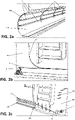
Figures 1a-1f show exemplary steps for carrying an HV cable near a tunnel entrance according to an embodiment of the method of the present disclosure; -
Figures 2a-2c and3a-3e show exemplary steps for the installation of a single span of HV cable in a tunnel. - For the purpose of the present description and of the appended claims, except where otherwise indicated, all numbers expressing amounts, quantities, percentages, and so forth, are to be understood as being modified in all instances by the term "about". Also, all ranges include any combination of the maximum and minimum points disclosed and include any intermediate ranges therein, which may or may not be specifically enumerated herein.
- The present disclosure, in at least one of the aforementioned aspects, can be implemented according to one or more of the following embodiments, optionally combined together.
- For the purpose of the present description and of the appended claims, the words "a" or "an" should be read to include one or at least one and the singular also includes the plural unless it is obvious that it is meant otherwise. This is done merely for convenience and to give a general sense of the disclosure.
- With reference to the attached Figures, the aim of the method and the equipment according to the present disclosure is installing a single span of
HV cable 100 in an intended deployment site. For example, a single span ofHV cable 100 to be installed from a starting point 101 (Fig. 1a ) to an end point 102 (Fig. 3e ), wherein part of the cable path is in atunnel 103 and the remaining parts are outside of the tunnel, can be guided from thestarting point 101 to thetunnel 103 and then pulled to theend point 102, as will be hereunder described. In the case depicted, thetunnel 103 is under the ground level and thestarting point 101 and theend point 102 are at the ground level. The cable path comprises an entrance shaft 104 (Fig. 1f ) and an exit shaft 105 (Fig. 3e ), respectively in communication with atunnel entrance 106 and atunnel exit 107. - As shown in
Fig. 1a , thesingle cable span 100 can be delivered at thestarting point 101 rolled in a basket or turntable ordrum 109, for example carried by avehicle 110, such as a wheeled vehicle or even a boat depending on the position of thestarting point 101. Thesingle cable span 100 can be initially unloaded from thebasket 109 using, for example, a pick-up arm (not shown in the figures) picking up a head portion thereof and moving it in a transition structure 111 (Fig. 1b ) guiding and holding thecable 100 from thebasket 109 towards the entrance shaft. During the movement of thecable 100 along thetransition structure 111, thecable 100 is progressively unloaded from thebasket 109. - In an embodiment shown in
Figure 1b , thetransition structure 111 can comprise several different structures such as metallic frames ortrenches 112 generally housing rollers, chutes orpushers 121, for moving, guiding and/or easing the advance of the cable towards the entrance shaft. Thetransition structure 111 can also comprise ajoint chamber 113 for the connection of the cable span to a cable of the network, once deployed. - As from
Figures 1c and 1d , aconveyor belt 20 is provided for joining thesingle cable span 100 to devices useful for the cable deployment. Theconveyor belt 20 can be positioned downstream with respect to thetransition structure 111 ofFig. 1b . For example, theconveyor belt 20 can be positioned at a ground level with respect to theentrance shaft 104 and the tunnel entrance 106 (see alsoFig. 1f ). However, according to another embodiment, theconveyor belt 20 can be positioned at a different location and/or at a different level with respect to the ground. - The
conveyor belt 20 forms a closed loop and is supported by a plurality of, optionally idle,rollers 21 determining the overall shape of theconveyor belt 20. Theconveyor belt 20 has anentry zone 22, where thecable span 100 arrives at theconveyor belt 20, a releasingzone 23, where thecable span 100 leaves theconveyor belt 20, and anintermediate zone 24 between theentry zone 22 and the releasingzone 23, where thecable span 100 is supported by theconveyor belt 20. When, according to the embodiment described, therollers 21 are idle, thecable span 100 translational movement causes an integral translational movement of theintermediate zone 24 of theconveyor belt 20 and consequently the rotational movement (in clockwise direction, with reference to theFigure 1d ) of theconveyor belt 20. Theconveyor belt 20intermediate zone 24 comprises anupper side 25 where thecable span 100 is actually connected to the conveyor belt itself, which is preferably horizontal. - In an embodiment, the conveyor
belt entry zone 22 may comprise anupper side 26 which forms an inclined surface whose height increases towards theintermediate zone 24upper side 25. - In an embodiment, the conveyor
belt releasing zone 23 may comprise anupper side 27 which forms a decreasing surface whose height decreases from theintermediate zone 24upper side 25. The so formed decreasing surface may be suitable for guiding thesingle cable span 100 downward for example when thetunnel 103 is at a lower level than the conveyor belt. - The
conveyor belt 20 comprises a plurality oflocations 28 arranged at a predetermined distance one from another along the longitudinal movement direction of theconveyor belt 20 and moving integrally with the latter. In an embodiment, thelocations 28 are in the form of strips extending substantially perpendicularly with respect to theconveyor belt 20 translational movement direction. Thelocations 28 can have any suitable form, from painted sign to marking strips to blocks optionally shaped to support a first part 13' of aholder 11 while the conveyor belt advances. - In an embodiment, each
holder 11, specifically asecond part 13" thereof, is connected to atrolley 8, as detailed in the following. - With reference to the embodiment detailed in
Fig.1e , eachlocation 28 may comprise aseat 29 where the first part 13' of theholder 11 is placed to house a cable span portion during the movement along the conveyor belt, for example along theintermediate zone 24 thereof. Once the cable span portion engaged the first part 13', thesecond part 13" of theholder 11 is joined to the first part 13', for example by a fastener (not shown), to lock acable span 100 portion within in a releasable manner. In an embodiment thesecond part 13" is connected to atrolley 8 at a side opposite to that joining the first part 13'. - A plurality of
holders 11 can be positioned inrespective locations 28 of theconveyor belt 20 at a predetermined distance. The distance between two holders 11 (and, accordingly, between the two locations occupied by such holders 11) is generally the same for all theholders 11 used for a given cable deployment. During the cable deployment, not all of thelocations 28 are occupied by arespective holder 11. For example, in theFigure 1d twoholders 11 carryingrespective trolleys 8 are shown at a distance of fourteen intermediate locations between each other. In correspondence of eachlocations 28 occupied by oneholder 11, thecable span 100 portion is supported by therespective holder 11. - In an embodiment, the
holder 11 may comprise a first part 13'and asecond part 13" which are releasably connectable in such a manner so to lock acable span 100 portion. For example, theholder 11 may be a clamp and the first part 13' and thesecond part 13" are two clamp halves. In an embodiment, thesecond part 13" may, in turn, be made of two sub-parts. One of the sub-parts may be suitable for the connection to the first part 13', and the other subpart may be suitable for the connection to thetrolley 8. - In an embodiment, each
holder 11, in particular its first part 13', andlocations 28 are configured such that when thecable span 100 portion connected to theholder 11 leaves theconveyor belt 20, theholder 11 vacates thelocation 28 without the need of any further intervention, for example by a user. - Each
holder 11 may comprise or be connectable to arespective trolley 8. In an embodiment, thesecond part 13" of theholder 11 is connectable to saidtrolley 8. Thetrolley 8 is suitable to slide along a guidingrail 30 which can be positioned along or downstream the conveyor belt 20 (the latter configuration being that ofFigs. 1c-1d ), for example near the releasingzone 23, for guiding thesingle cable span 100 towards thetunnel entrance 106, as shown inFigures 1d and1f . The guidingrail 30, therefore, supports thetrolley 8 which in turns supports thecable span 100 after it left theconveyor belt 20. In the case theconveyor belt 20 and thetunnel 103 are at different level, the guidingrail 30 forms a path along theentrance shaft 104 for guiding the single cable span from the level where theconveyor belt 20 is located to the level where thetunnel 103 is located. - It is to be noted that the guiding
rail 30 can be quite short or even missing, for example if theconveyor belt 20 and thetunnel 103 are at the same level and/or at a short distance. - As from
Fig. 1f (where, just for the sake of clarity, the guidingrail 30 and therail 1 are not depicted), in order to position thehead portion 108 of thecable span 100 near thetunnel entrance 106, an auxiliary pulling device, such as anauxiliary entrance winch 115, can be provided at the bottom of theentrance shaft 104 to pull thecable head portion 108 near thetunnel entrance 106 through an entranceauxiliary rope 122. The above-mentionedpushers 121 and theauxiliary entrance winch 115 can be driven in a synchronized manner. - As from
Fig. 2a , at least onerail 1 is installed in thetunnel 103, longitudinally extending along the same, from thetunnel entrance 106 to the tunnel exit 107 (Fig. 2c ). Thetunnel rail 1 can be an extension of the guidingrail 30, when the latter is provided. - In an embodiment, one
rail 1 is fixed at the tunnel wall for eachsingle cable span 100 to be deployed in thetunnel 103. In case of a plurality of cables to be installed, a corresponding plurality ofrails 1, substantially parallel one another, can be installed (as fromFig. 2a ), before or after the deployment of a cable span on a rail. In case of atunnel 103 having circular or semi-circular cross section, for example, therails 1 are installed to the tunnel wall circumferentially along the cylindrical tunnel wall, parallel to the longitudinal axis thereof. - In an embodiment, in order to install the
rail 1 in thetunnel 103, a plurality ofrail support structures 2 for supporting therails 103 are fixed along the tunnel to the tunnel walls. Therail support structures 2 are, for example, made of steel and can be spaced along the tunnel length of the same distance, for example no longer than 9 meters. In an embodiment, therail support structures 2 are arc-shaped to fit the circular or semi-circular tunnel wall, as shown for example inFigure 2a . Therails 1 and therail support structures 2 are fixedly installed in thetunnel 103 because they are used both for laying thesingle cable span 100 and for keeping the same in thetunnel 103 once the installation is completed, as will be described in more detail in the following. - In order to minimize the friction with the guiding
rail 30 and/or with thetunnel rail 1, thetrolley 8 can comprise bearings 9 with low friction coefficient (as fromFig. 3a ). In an embodiment, the guidingrail 30 and/or thetunnel rail 1 are I-shaped and the bearings 9 engage the I-shaped rail on both sides thereof. - In an embodiment, a pulling
device 3, for example comprising a pulling winch, is installed near thetunnel exit 107, for example at theexit shaft 105, as fromFigure 2c . A rope buffer, for example comprising anidle roller 4, is provided near thetunnel entrance 106, for example at theentrance shaft 104, as fromFigure 2b . A pullingrope 5 is stored in the rope buffer, for example is wound in theidle roller 4, and, by extending longitudinally along thetunnel 103, is connected to the pullingwinch 3 such that the pullingwinch 3 can pull therope 5 stored in theidle roller 4. In an embodiment, the pullingrope 5 is positioned to extend parallel to and near therail 1. - As from
Figure 3b , when thefirst trolley 8, connected to thecable span 100 portion at theconveyor belt 20 as described above, reaches thetunnel rail 1 from the guidingrail 30 at thetunnel entrance 106, then thetrolley 8 is connected to therope 5. To this purpose, as fromFig. 3a , thetrolley 8 comprises arope clamp 10 for the releasable connection of therope 5 to thetrolley 8. In an embodiment, therope clamp 10 comprises twohalves 12', 12". Once connected to therope 5, thetrolley 8 carrying thecable span 100 can be made to slide along therail 1 thanks to the pulling force exerted by the pullingrope 5 and can integrally carry thecable 100 with no pulling stress exerted thereon. The pullingrope 5 is driven by the pulling device 3 (Figure 2c ). - Then, the
other trolleys 8, having the same features of thefirst trolley 8, reach, one after the other, therail 1 at thetunnel entrance 106 and are successively connected to therope 5 as described for the first trolley. Eachfurther trolley 8 is made to slide along therail 1 as already described for thefirst trolley 8. During this operation, thesingle cable span 100 longitudinally moves further along therail 1, accordingly. - Once the
first trolley 8 reaches the tunnel rail end near thetunnel exit 107, thecable head portion 108 is detached from thefirst trolley 8. - The
single cable span 100 is further moved on until thecable head portion 108 is carried to and outside theexit shaft 105, particularly it reaches theoverhead end point 102, as fromFigure 3e . During this moving, thecable span 100 is detached from a suitable number oftrolleys 8. - In an embodiment, an auxiliary pulling device, such as an
auxiliary exit winch 116, is positioned at the overhead endpoint 102 (Figure 3e ). The auxiliary pulling device drives an exit auxiliary pulling rope (not shown in the Figures) connected to thecable head portion 108 to pull thesingle cable span 100 towards theendpoint 102. The pulling force exerted by the exit auxiliary pulling rope on the cable head portion 108 (and, accordingly, on the single cable span 100) is relieved by the tractive force of the pullingrope 5 still operatively connected to most of the single cable span length. - An
exit transition structure 117 guiding and holding thesingle cable span 100 and the exit auxiliary pulling rope from thetunnel exit 107 through theexit shaft 105 is provided. Asecond trench 118 can connect theend point 102 to theexit shaft 105. - In an embodiment, a plurality of
supports 120, for example made of steel, are installed in theexit shaft 105. Thesupports 120 can have rollers for guiding thecable head portion 108 and the auxiliary pulling rope. - At the
end point 102,cable head portion 108 of thesingle cable span 100 can be connected to one or more power cables of the electric network by a second joint chamber (not illustrated). - As mentioned above, in order to raise the
head portion 108 of thesingle cable span 100 outside thetunnel 107, the pullingrope 5 and a predetermined number oftrolleys 8 are disconnected from thesingle cable span 100, and thedisconnected trolleys 8 are removed from the rail 1 (Fig. 3c ). Then, as shown in theFigure 3d , both the pulling rope 5 (which keeps on pulling thefurther trolleys 8 and, accordingly, thesingle cable span 100 connected thereto) and the exit auxiliary pulling rope (connected to the cable head portion 118) driven by theauxiliary exit winch 116 are pulled, for example in a synchronized manner, until thecable head portion 108 reaches a predetermined position outside the tunnel, for example until it reaches theendpoint 102. Depending on the length of thesingle cable span 100 to be extracted from thetunnel 103, beside thefirst trolley 8,further trolleys 8 can be sequentially disconnected from the pullingrope 5 and from thesingle cable span 100 and removed from therail 1. - In an embodiment, once the
cable head portion 108 reached theendpoint 102, at least a number or all of thetrolleys 8 inside thetunnel 103 can be left in position, optionally locked, on therail 1, thus providing a permanent support for the deployedcable span 100. The choice about the number oftrolleys 8 to be left into thetunnel 103 can be determined by installation considerations like the cable weight or the sought sagging. - Similarly, once the
cable head portion 108 reached theendpoint 102, a number oftrolleys 8 may remain along the guidingrail 30, if provided. These trolleys can be left in position, optionally locked, on the guidingrail 30. - According to an embodiment, when the
cable head portion 108 reached a predetermined end point outside of the tunnel, the pulling rope is left joined to the trolleys inside the tunnel. - Accordingly, a method for installing the single
power cable span 100 in a deployment site comprising a rail for supporting the single cable span, for example thetunnel rail 1, comprises the steps of: - providing a
conveyor belt 20 as described above; - repeating the following steps until the
cable span 100 reaches a predetermined position (such as, for example, thetunnel entrance 106 or the endpoint 102):- ∘ while the
conveyor belt 20 is moving, positioning a first part 13' of theholder 11 to one of thelocations 28, for example at the conveyorbelt entry zone 22. In an embodiment, this step comprises engaging the first part 13' of theholder 11 in theseat 29 of one thelocations 28 and is repeated for eachlocation 28 at a predetermined distance from the previously occupiedlocation 28. Theconveyor belt 20 moving may be obtained by thesingle cable span 100 advancing; - ∘ while advancing the
single cable span 100, laying a portion of the single cable span in the part of theholder 11 positioned to thelocation 28 and locking this cable span portion to theholder 11. These positioning and locking steps may take place at the conveyor beltintermediate zone 24. In an embodiment, the locking step may comprise connecting thesecond part 13" to thefirst part 13" in such a manner so to clamp thecable span 100 portion between the two parts of theholder 11; - ∘ while the
cable span 100 portion engaged by theholder 11 is leaving theconveyor belt 20, for example at the conveyorbelt releasing zone 23, removing theholder 11 from thelocation 28 moving with theconveyor belt 20. In an embodiment, this removing step comprises separating the first part 13' from theseat 29 of thelocation 28.
- ∘ while the
- In an embodiment, the
holder 11, for example thesecond part 13", comprises or is connected to thetrolley 8. Alternatively, the method further comprises the step of connecting theholder 11, particularly thesecond part 13", already locked to the cable span portion, to atrolley 8. This step preferably takes place at theintermediate zone 24 of theconveyor belt 20. - In an embodiment, after the above-cited disengagement, the method further comprises coupling the
trolley 8 connected to the cable span portion to the guidingrail 30 while thesingle cable span 100 is advancing. In this manner the single cable span can be guided towards a position, for example at a lower level than the conveyor belt, towards, e.g., thetunnel entrance 106. - During the above-mentioned steps, the advancing of the
single cable span 100 can be obtained by pulling thehead portion 108 with theauxiliary rope 122. - Once the
cable head portion 108 has reached, for example, thetunnel entrance 106, if it is necessary to further move thecable span 100, for example towards another position such as theendpoint 102, the method according to the disclosure can further comprise, until it reaches said position, the following steps: - at the
tunnel entrance 106 connecting onetrolley 8 at thetunnel rail 1. As the guidingrail 30 and thetunnel rail 1 are continuously connected so to form a single rail, this connection can be obtained by continuously moving in a slidable manner the trolley from the guidingrail 30 to thetunnel rail 1; - joining the
trolley 8 to the pullingrope 5; - moving the
trolley 8 along thetunnel rail 1 by pulling the pullingrope 5; - at the
tunnel exit 107 disconnecting thetrolley 8 from the pullingrope 5 and from thesingle cable span 100 and removing it from thetunnel rail 1. - In an embodiment, the method further comprises the step of locking at least the
trolley 8 nearest to thetunnel exit 107 on thetunnel rail 1 when thecable head portion 108 has reached the desired end position. - When the cable head portion reached a predetermined end point outside of the tunnel, the installation is taken as finished. Subsequently, the single cable span so installed can be connected to the power network by, for example, the first and second joint chambers mentioned above.
Claims (15)
- Method for installing a single power cable span (100) in a deployment site comprising a rail (1; 30) for supporting the single cable span (100) by trolleys (8), the method comprising the steps of:- providing a conveyor belt (20) outside of the deployment site, the conveyor belt (20) having a plurality of locations (28) set at a predetermined distance one from the other along a longitudinal movement direction of the conveyor belt (20) and moving integrally with the latter;- repeating the following steps until the single cable span (100) reaches a predetermined position:∘ while the conveyor belt (20) is moving, positioning a first part (13') of a holder (11) at one of the locations (28);∘ while advancing the single cable span (100), laying a portion thereof on said first part (13') of the holder (11) positioned at the location (28) moving with the conveyor belt (20);∘ connecting a second part (13") of the holder (11) to the first one (13') to lock the cable span portion in between;∘ while the cable span (100) portion locked by the holder (11) is leaving the conveyor belt (20), removing the first part (13') of the holder (11) from the location (28) moving with the conveyor belt (20).
- The method of claim 1, wherein the second part (13") of the holder (11) is engaged to one trolley (8) before being connected to the first part (13').
- The method of claim 1, wherein the second part (13") of the holder (11) is engaged to one trolley (8) after having been connected to the first part (13').
- The method of claim 1, wherein the second part (13") of the holder (11) is engaged to one trolley (8) once the first part (13') is removed from its location (28).
- The method of claim 1, wherein the conveyor belt (20) moving is caused by the single cable span (100) advancing.
- The method of claim 1, wherein the conveyor belt (20) comprises an entry zone (22), a releasing zone (23) and an intermediate zone (24) between the entry zone (22) and the releasing zone (23), wherein the single cable span (100) is laid on the first part (13') at the intermediate zone (24).
- The method of claim 6, wherein the first part (13') of a holder (11) is positioned at one of the locations (28) in the entry zone (22) of the conveyor belt (20).
- The method of claim 6, wherein the holder device (11) leaves the location (28) at the conveyor belt releasing zone (23).
- The method of claim 1, wherein the holders (11) are provided at locations (28) set at a distance which is the same for a given cable deployment.
- The method of claim 1, further comprising the step of coupling the trolleys (8) to a guiding rail (30) or to a rail (1).
- Equipment for the installation of a single power cable span (100) in a deployment site comprising:- at least one rail (1; 30) to be fixedly installed in said deployment site;- a plurality of trolleys (8) slidably couplable to the at least one rail (1; 30); a plurality of holders (11) for releasably connecting the single cable span (100) to one of said trolleys (8), each holder comprising a first part (13') and a second part (13");- a conveyor belt (20) having a plurality of locations (28) arranged at a predetermined distance one from the other along a longitudinal movement direction of the conveyor belt (20) and movable integrally with the latter, wherein each of the locations (28) is suitable for positioning the first part (13') of one of said holders (11).
- The equipment of claim 11, wherein the locations (28) are in form of strips extending transversally with respect to the conveyor belt translational movement direction.
- The equipment of claim 11, wherein the second part (13") of the holder (11) is connected or connectable to one of said trolleys (8).
- The equipment of claim 11, wherein said at least one rail comprises a guiding rail (30).
- The equipment of claim 11, wherein each of said trolleys (8) comprises a rope clamp (10) for releasably connecting the trolley (8) to a pulling rope (5).
Applications Claiming Priority (1)
| Application Number | Priority Date | Filing Date | Title |
|---|---|---|---|
| IT102021000011645A IT202100011645A1 (en) | 2021-05-06 | 2021-05-06 | METHOD AND EQUIPMENT FOR INSTALLING A POWER CABLE IN AN INSTALLATION SITE |
Publications (3)
| Publication Number | Publication Date |
|---|---|
| EP4087074A1 true EP4087074A1 (en) | 2022-11-09 |
| EP4087074C0 EP4087074C0 (en) | 2023-12-13 |
| EP4087074B1 EP4087074B1 (en) | 2023-12-13 |
Family
ID=76808094
Family Applications (1)
| Application Number | Title | Priority Date | Filing Date |
|---|---|---|---|
| EP22167333.8A Active EP4087074B1 (en) | 2021-05-06 | 2022-04-08 | Method and equipment for installing a power cable in a deployment site |
Country Status (6)
| Country | Link |
|---|---|
| US (1) | US12355219B2 (en) |
| EP (1) | EP4087074B1 (en) |
| CN (1) | CN115313247A (en) |
| AU (1) | AU2022203012A1 (en) |
| CA (1) | CA3157205A1 (en) |
| IT (1) | IT202100011645A1 (en) |
Cited By (1)
| Publication number | Priority date | Publication date | Assignee | Title |
|---|---|---|---|---|
| CN116927587A (en) * | 2023-08-09 | 2023-10-24 | 杭州富阳红润塑胶电器有限公司 | Farm fence turntable capable of being automatically retracted and retracted at fixed distance |
Families Citing this family (3)
| Publication number | Priority date | Publication date | Assignee | Title |
|---|---|---|---|---|
| IT202100011645A1 (en) | 2021-05-06 | 2022-11-06 | Prysmian Spa | METHOD AND EQUIPMENT FOR INSTALLING A POWER CABLE IN AN INSTALLATION SITE |
| IT202100017399A1 (en) | 2021-07-01 | 2023-01-01 | Prysmian Spa | Method for scalloping a power cable |
| CN116890076B (en) * | 2023-06-08 | 2025-09-30 | 江西电缆有限责任公司 | Secondary cable core straightening device and method |
Citations (5)
| Publication number | Priority date | Publication date | Assignee | Title |
|---|---|---|---|---|
| GB2383200A (en) | 2001-12-12 | 2003-06-18 | Balfour Beatty Plc | Cable positioning system having a belt |
| GB2468883A (en) * | 2009-03-25 | 2010-09-29 | Balfour Beatty Plc | Method and apparatus for the installation of cables or pipes in tunnels |
| KR20170061932A (en) * | 2015-11-27 | 2017-06-07 | 주명석 | Installation Method Of Underground Power Cable |
| KR101915432B1 (en) * | 2018-01-29 | 2018-11-05 | 이상균 | Electric cable install apparatus and method with movable installer |
| CN110212458A (en) | 2019-05-24 | 2019-09-06 | 南京市第六建筑安装工程有限公司 | A kind of cable tunnel that can be laid with cable automatically |
Family Cites Families (5)
| Publication number | Priority date | Publication date | Assignee | Title |
|---|---|---|---|---|
| JP2652602B2 (en) | 1992-05-12 | 1997-09-10 | 未来工業株式会社 | Wiring and piping material suspension members and wiring and piping equipment |
| GB2495503A (en) | 2011-10-11 | 2013-04-17 | Balfour Beatty Plc | Method and apparatus for the installation of cables or pipes in tunnels |
| GB2554873B (en) | 2016-10-07 | 2022-04-27 | Balfour Beatty Plc | A mobile support for use in a utility service installation system and method |
| IT202000019975A1 (en) | 2020-08-11 | 2022-02-11 | Prysmian Spa | METHOD AND EQUIPMENT FOR INSTALLING A POWER CABLE IN A TUNNEL |
| IT202100011645A1 (en) | 2021-05-06 | 2022-11-06 | Prysmian Spa | METHOD AND EQUIPMENT FOR INSTALLING A POWER CABLE IN AN INSTALLATION SITE |
-
2021
- 2021-05-06 IT IT102021000011645A patent/IT202100011645A1/en unknown
-
2022
- 2022-04-08 EP EP22167333.8A patent/EP4087074B1/en active Active
- 2022-04-29 CN CN202210471788.9A patent/CN115313247A/en active Pending
- 2022-05-03 US US17/661,897 patent/US12355219B2/en active Active
- 2022-05-03 CA CA3157205A patent/CA3157205A1/en active Pending
- 2022-05-05 AU AU2022203012A patent/AU2022203012A1/en active Pending
Patent Citations (5)
| Publication number | Priority date | Publication date | Assignee | Title |
|---|---|---|---|---|
| GB2383200A (en) | 2001-12-12 | 2003-06-18 | Balfour Beatty Plc | Cable positioning system having a belt |
| GB2468883A (en) * | 2009-03-25 | 2010-09-29 | Balfour Beatty Plc | Method and apparatus for the installation of cables or pipes in tunnels |
| KR20170061932A (en) * | 2015-11-27 | 2017-06-07 | 주명석 | Installation Method Of Underground Power Cable |
| KR101915432B1 (en) * | 2018-01-29 | 2018-11-05 | 이상균 | Electric cable install apparatus and method with movable installer |
| CN110212458A (en) | 2019-05-24 | 2019-09-06 | 南京市第六建筑安装工程有限公司 | A kind of cable tunnel that can be laid with cable automatically |
Cited By (1)
| Publication number | Priority date | Publication date | Assignee | Title |
|---|---|---|---|---|
| CN116927587A (en) * | 2023-08-09 | 2023-10-24 | 杭州富阳红润塑胶电器有限公司 | Farm fence turntable capable of being automatically retracted and retracted at fixed distance |
Also Published As
| Publication number | Publication date |
|---|---|
| CA3157205A1 (en) | 2022-11-06 |
| EP4087074C0 (en) | 2023-12-13 |
| US12355219B2 (en) | 2025-07-08 |
| AU2022203012A1 (en) | 2022-11-24 |
| US20220360057A1 (en) | 2022-11-10 |
| CN115313247A (en) | 2022-11-08 |
| EP4087074B1 (en) | 2023-12-13 |
| IT202100011645A1 (en) | 2022-11-06 |
Similar Documents
| Publication | Publication Date | Title |
|---|---|---|
| US12355219B2 (en) | Method and equipment for installing a power cable in a deployment site | |
| US11894667B2 (en) | Method and equipment for the installation of a power cable in a tunnel | |
| JP7271795B2 (en) | Attaching cables and other components to the wind turbine tower | |
| JP2652602B2 (en) | Wiring and piping material suspension members and wiring and piping equipment | |
| US20140090576A1 (en) | Umbilical cart and system | |
| US8622656B2 (en) | Apparatus, systems and methods for the relocation of subsurface conduit | |
| CN112324991B (en) | Device for laying deep groove pipeline | |
| KR20230037215A (en) | underground transmission cable removal new construction method using the deconstruction cutting pulling apparatus of the underground power cable | |
| KR102559106B1 (en) | deconstruction cutting pulling apparatus of the underground power cable | |
| CN109787157A (en) | Offshore structure and method of apparatus for attaching pipe or cable to offshore structure | |
| US12126150B2 (en) | Method for festooning a power cable | |
| KR102658487B1 (en) | underground transmission cable removal new construction method using the deconstruction cutting pulling apparatus of the underground power cable | |
| BR102024005641A2 (en) | SUPPORT STRUCTURE AND MECHANIZED CABLE LAUNCHING SYSTEM | |
| CN222410908U (en) | Pipe fitting conveyer | |
| CA1058891A (en) | Under ice pipelaying | |
| CN120175227A (en) | A mobile cable tray | |
| CN117429827A (en) | A dual-track combined transportation system for rapid maintenance and emergency repair of pipelines in loess gully areas | |
| HU204909B (en) | A method of constructing a closed-loop line artwork, in particular a creepy or walkable gutter tube, and an auxiliary device for performing the process |
Legal Events
| Date | Code | Title | Description |
|---|---|---|---|
| PUAI | Public reference made under article 153(3) epc to a published international application that has entered the european phase |
Free format text: ORIGINAL CODE: 0009012 |
|
| STAA | Information on the status of an ep patent application or granted ep patent |
Free format text: STATUS: THE APPLICATION HAS BEEN PUBLISHED |
|
| AK | Designated contracting states |
Kind code of ref document: A1 Designated state(s): AL AT BE BG CH CY CZ DE DK EE ES FI FR GB GR HR HU IE IS IT LI LT LU LV MC MK MT NL NO PL PT RO RS SE SI SK SM TR |
|
| STAA | Information on the status of an ep patent application or granted ep patent |
Free format text: STATUS: REQUEST FOR EXAMINATION WAS MADE |
|
| 17P | Request for examination filed |
Effective date: 20230413 |
|
| RBV | Designated contracting states (corrected) |
Designated state(s): AL AT BE BG CH CY CZ DE DK EE ES FI FR GB GR HR HU IE IS IT LI LT LU LV MC MK MT NL NO PL PT RO RS SE SI SK SM TR |
|
| GRAP | Despatch of communication of intention to grant a patent |
Free format text: ORIGINAL CODE: EPIDOSNIGR1 |
|
| STAA | Information on the status of an ep patent application or granted ep patent |
Free format text: STATUS: GRANT OF PATENT IS INTENDED |
|
| RIC1 | Information provided on ipc code assigned before grant |
Ipc: H02G 9/06 20060101ALN20230627BHEP Ipc: B08B 9/043 20060101ALN20230627BHEP Ipc: H02G 11/02 20060101ALI20230627BHEP Ipc: G02B 6/44 20060101ALI20230627BHEP Ipc: H02G 9/08 20060101ALI20230627BHEP Ipc: H02G 1/08 20060101AFI20230627BHEP |
|
| INTG | Intention to grant announced |
Effective date: 20230717 |
|
| GRAS | Grant fee paid |
Free format text: ORIGINAL CODE: EPIDOSNIGR3 |
|
| GRAA | (expected) grant |
Free format text: ORIGINAL CODE: 0009210 |
|
| STAA | Information on the status of an ep patent application or granted ep patent |
Free format text: STATUS: THE PATENT HAS BEEN GRANTED |
|
| AK | Designated contracting states |
Kind code of ref document: B1 Designated state(s): AL AT BE BG CH CY CZ DE DK EE ES FI FR GB GR HR HU IE IS IT LI LT LU LV MC MK MT NL NO PL PT RO RS SE SI SK SM TR |
|
| REG | Reference to a national code |
Ref country code: GB Ref legal event code: FG4D |
|
| REG | Reference to a national code |
Ref country code: CH Ref legal event code: EP |
|
| REG | Reference to a national code |
Ref country code: DE Ref legal event code: R096 Ref document number: 602022001269 Country of ref document: DE |
|
| REG | Reference to a national code |
Ref country code: IE Ref legal event code: FG4D |
|
| U01 | Request for unitary effect filed |
Effective date: 20231219 |
|
| U07 | Unitary effect registered |
Designated state(s): AT BE BG DE DK EE FI FR IT LT LU LV MT NL PT SE SI Effective date: 20240102 |
|
| REG | Reference to a national code |
Ref country code: NO Ref legal event code: T2 Effective date: 20231213 |
|
| PG25 | Lapsed in a contracting state [announced via postgrant information from national office to epo] |
Ref country code: GR Free format text: LAPSE BECAUSE OF FAILURE TO SUBMIT A TRANSLATION OF THE DESCRIPTION OR TO PAY THE FEE WITHIN THE PRESCRIBED TIME-LIMIT Effective date: 20240314 |
|
| PG25 | Lapsed in a contracting state [announced via postgrant information from national office to epo] |
Ref country code: ES Free format text: LAPSE BECAUSE OF FAILURE TO SUBMIT A TRANSLATION OF THE DESCRIPTION OR TO PAY THE FEE WITHIN THE PRESCRIBED TIME-LIMIT Effective date: 20231213 |
|
| PG25 | Lapsed in a contracting state [announced via postgrant information from national office to epo] |
Ref country code: GR Free format text: LAPSE BECAUSE OF FAILURE TO SUBMIT A TRANSLATION OF THE DESCRIPTION OR TO PAY THE FEE WITHIN THE PRESCRIBED TIME-LIMIT Effective date: 20240314 Ref country code: ES Free format text: LAPSE BECAUSE OF FAILURE TO SUBMIT A TRANSLATION OF THE DESCRIPTION OR TO PAY THE FEE WITHIN THE PRESCRIBED TIME-LIMIT Effective date: 20231213 |
|
| PG25 | Lapsed in a contracting state [announced via postgrant information from national office to epo] |
Ref country code: RS Free format text: LAPSE BECAUSE OF FAILURE TO SUBMIT A TRANSLATION OF THE DESCRIPTION OR TO PAY THE FEE WITHIN THE PRESCRIBED TIME-LIMIT Effective date: 20231213 Ref country code: HR Free format text: LAPSE BECAUSE OF FAILURE TO SUBMIT A TRANSLATION OF THE DESCRIPTION OR TO PAY THE FEE WITHIN THE PRESCRIBED TIME-LIMIT Effective date: 20231213 |
|
| U20 | Renewal fee for the european patent with unitary effect paid |
Year of fee payment: 3 Effective date: 20240429 |
|
| PG25 | Lapsed in a contracting state [announced via postgrant information from national office to epo] |
Ref country code: IS Free format text: LAPSE BECAUSE OF FAILURE TO SUBMIT A TRANSLATION OF THE DESCRIPTION OR TO PAY THE FEE WITHIN THE PRESCRIBED TIME-LIMIT Effective date: 20240413 |
|
| PG25 | Lapsed in a contracting state [announced via postgrant information from national office to epo] |
Ref country code: CZ Free format text: LAPSE BECAUSE OF FAILURE TO SUBMIT A TRANSLATION OF THE DESCRIPTION OR TO PAY THE FEE WITHIN THE PRESCRIBED TIME-LIMIT Effective date: 20231213 |
|
| PG25 | Lapsed in a contracting state [announced via postgrant information from national office to epo] |
Ref country code: SK Free format text: LAPSE BECAUSE OF FAILURE TO SUBMIT A TRANSLATION OF THE DESCRIPTION OR TO PAY THE FEE WITHIN THE PRESCRIBED TIME-LIMIT Effective date: 20231213 |
|
| PG25 | Lapsed in a contracting state [announced via postgrant information from national office to epo] |
Ref country code: SM Free format text: LAPSE BECAUSE OF FAILURE TO SUBMIT A TRANSLATION OF THE DESCRIPTION OR TO PAY THE FEE WITHIN THE PRESCRIBED TIME-LIMIT Effective date: 20231213 Ref country code: SK Free format text: LAPSE BECAUSE OF FAILURE TO SUBMIT A TRANSLATION OF THE DESCRIPTION OR TO PAY THE FEE WITHIN THE PRESCRIBED TIME-LIMIT Effective date: 20231213 Ref country code: RO Free format text: LAPSE BECAUSE OF FAILURE TO SUBMIT A TRANSLATION OF THE DESCRIPTION OR TO PAY THE FEE WITHIN THE PRESCRIBED TIME-LIMIT Effective date: 20231213 Ref country code: IS Free format text: LAPSE BECAUSE OF FAILURE TO SUBMIT A TRANSLATION OF THE DESCRIPTION OR TO PAY THE FEE WITHIN THE PRESCRIBED TIME-LIMIT Effective date: 20240413 Ref country code: CZ Free format text: LAPSE BECAUSE OF FAILURE TO SUBMIT A TRANSLATION OF THE DESCRIPTION OR TO PAY THE FEE WITHIN THE PRESCRIBED TIME-LIMIT Effective date: 20231213 |
|
| PG25 | Lapsed in a contracting state [announced via postgrant information from national office to epo] |
Ref country code: PL Free format text: LAPSE BECAUSE OF FAILURE TO SUBMIT A TRANSLATION OF THE DESCRIPTION OR TO PAY THE FEE WITHIN THE PRESCRIBED TIME-LIMIT Effective date: 20231213 |
|
| PG25 | Lapsed in a contracting state [announced via postgrant information from national office to epo] |
Ref country code: PL Free format text: LAPSE BECAUSE OF FAILURE TO SUBMIT A TRANSLATION OF THE DESCRIPTION OR TO PAY THE FEE WITHIN THE PRESCRIBED TIME-LIMIT Effective date: 20231213 |
|
| REG | Reference to a national code |
Ref country code: DE Ref legal event code: R097 Ref document number: 602022001269 Country of ref document: DE |
|
| PLBE | No opposition filed within time limit |
Free format text: ORIGINAL CODE: 0009261 |
|
| STAA | Information on the status of an ep patent application or granted ep patent |
Free format text: STATUS: NO OPPOSITION FILED WITHIN TIME LIMIT |
|
| 26N | No opposition filed |
Effective date: 20240916 |
|
| PG25 | Lapsed in a contracting state [announced via postgrant information from national office to epo] |
Ref country code: MC Free format text: LAPSE BECAUSE OF FAILURE TO SUBMIT A TRANSLATION OF THE DESCRIPTION OR TO PAY THE FEE WITHIN THE PRESCRIBED TIME-LIMIT Effective date: 20231213 |
|
| PG25 | Lapsed in a contracting state [announced via postgrant information from national office to epo] |
Ref country code: MC Free format text: LAPSE BECAUSE OF FAILURE TO SUBMIT A TRANSLATION OF THE DESCRIPTION OR TO PAY THE FEE WITHIN THE PRESCRIBED TIME-LIMIT Effective date: 20231213 |
|
| PG25 | Lapsed in a contracting state [announced via postgrant information from national office to epo] |
Ref country code: IE Free format text: LAPSE BECAUSE OF NON-PAYMENT OF DUE FEES Effective date: 20240408 |
|
| U20 | Renewal fee for the european patent with unitary effect paid |
Year of fee payment: 4 Effective date: 20250428 |
|
| PG25 | Lapsed in a contracting state [announced via postgrant information from national office to epo] |
Ref country code: CY Free format text: LAPSE BECAUSE OF FAILURE TO SUBMIT A TRANSLATION OF THE DESCRIPTION OR TO PAY THE FEE WITHIN THE PRESCRIBED TIME-LIMIT; INVALID AB INITIO Effective date: 20220408 |
|
| PG25 | Lapsed in a contracting state [announced via postgrant information from national office to epo] |
Ref country code: HU Free format text: LAPSE BECAUSE OF FAILURE TO SUBMIT A TRANSLATION OF THE DESCRIPTION OR TO PAY THE FEE WITHIN THE PRESCRIBED TIME-LIMIT; INVALID AB INITIO Effective date: 20220408 |
|
| REG | Reference to a national code |
Ref country code: CH Ref legal event code: H13 Free format text: ST27 STATUS EVENT CODE: U-0-0-H10-H13 (AS PROVIDED BY THE NATIONAL OFFICE) Effective date: 20251125 |
|
| PG25 | Lapsed in a contracting state [announced via postgrant information from national office to epo] |
Ref country code: CH Free format text: LAPSE BECAUSE OF NON-PAYMENT OF DUE FEES Effective date: 20250430 |
|
| PG25 | Lapsed in a contracting state [announced via postgrant information from national office to epo] |
Ref country code: TR Free format text: LAPSE BECAUSE OF FAILURE TO SUBMIT A TRANSLATION OF THE DESCRIPTION OR TO PAY THE FEE WITHIN THE PRESCRIBED TIME-LIMIT Effective date: 20231213 |
|
| U20 | Renewal fee for the european patent with unitary effect paid |
Year of fee payment: 5 Effective date: 20260427 |
|
| PG25 | Lapsed in a contracting state [announced via postgrant information from national office to epo] |
Ref country code: CH Free format text: THE PATENT HAS BEEN ANNULLED BY A DECISION OF A NATIONAL AUTHORITY Effective date: 20250430 |
|
| PGFP | Annual fee paid to national office [announced via postgrant information from national office to epo] |
Ref country code: NO Payment date: 20260429 Year of fee payment: 5 |