EP4087054A1 - Communication apparatus for vehicle and control method therefor - Google Patents
Communication apparatus for vehicle and control method therefor Download PDFInfo
- Publication number
- EP4087054A1 EP4087054A1 EP20909090.1A EP20909090A EP4087054A1 EP 4087054 A1 EP4087054 A1 EP 4087054A1 EP 20909090 A EP20909090 A EP 20909090A EP 4087054 A1 EP4087054 A1 EP 4087054A1
- Authority
- EP
- European Patent Office
- Prior art keywords
- antenna
- switch
- antennas
- communication apparatus
- circuit
- Prior art date
- Legal status (The legal status is an assumption and is not a legal conclusion. Google has not performed a legal analysis and makes no representation as to the accuracy of the status listed.)
- Pending
Links
Images


Classifications
-
- H—ELECTRICITY
- H01—ELECTRIC ELEMENTS
- H01Q—ANTENNAS, i.e. RADIO AERIALS
- H01Q1/00—Details of, or arrangements associated with, antennas
- H01Q1/27—Adaptation for use in or on movable bodies
- H01Q1/32—Adaptation for use in or on road or rail vehicles
- H01Q1/325—Adaptation for use in or on road or rail vehicles characterised by the location of the antenna on the vehicle
-
- H—ELECTRICITY
- H01—ELECTRIC ELEMENTS
- H01Q—ANTENNAS, i.e. RADIO AERIALS
- H01Q1/00—Details of, or arrangements associated with, antennas
- H01Q1/27—Adaptation for use in or on movable bodies
- H01Q1/32—Adaptation for use in or on road or rail vehicles
- H01Q1/3208—Adaptation for use in or on road or rail vehicles characterised by the application wherein the antenna is used
-
- H—ELECTRICITY
- H01—ELECTRIC ELEMENTS
- H01Q—ANTENNAS, i.e. RADIO AERIALS
- H01Q3/00—Arrangements for changing or varying the orientation or the shape of the directional pattern of the waves radiated from an antenna or antenna system
- H01Q3/24—Arrangements for changing or varying the orientation or the shape of the directional pattern of the waves radiated from an antenna or antenna system varying the orientation by switching energy from one active radiating element to another, e.g. for beam switching
-
- H—ELECTRICITY
- H01—ELECTRIC ELEMENTS
- H01Q—ANTENNAS, i.e. RADIO AERIALS
- H01Q1/00—Details of, or arrangements associated with, antennas
- H01Q1/27—Adaptation for use in or on movable bodies
- H01Q1/32—Adaptation for use in or on road or rail vehicles
-
- H—ELECTRICITY
- H01—ELECTRIC ELEMENTS
- H01Q—ANTENNAS, i.e. RADIO AERIALS
- H01Q5/00—Arrangements for simultaneous operation of antennas on two or more different wavebands, e.g. dual-band or multi-band arrangements
- H01Q5/50—Feeding or matching arrangements for broad-band or multi-band operation
-
- H—ELECTRICITY
- H01—ELECTRIC ELEMENTS
- H01Q—ANTENNAS, i.e. RADIO AERIALS
- H01Q9/00—Electrically-short antennas having dimensions not more than twice the operating wavelength and consisting of conductive active radiating elements
- H01Q9/04—Resonant antennas
- H01Q9/0407—Substantially flat resonant element parallel to ground plane, e.g. patch antenna
-
- H—ELECTRICITY
- H04—ELECTRIC COMMUNICATION TECHNIQUE
- H04B—TRANSMISSION
- H04B1/00—Details of transmission systems, not covered by a single one of groups H04B3/00 - H04B13/00; Details of transmission systems not characterised by the medium used for transmission
- H04B1/02—Transmitters
- H04B1/04—Circuits
- H04B1/0458—Arrangements for matching and coupling between power amplifier and antenna or between amplifying stages
-
- H—ELECTRICITY
- H04—ELECTRIC COMMUNICATION TECHNIQUE
- H04B—TRANSMISSION
- H04B1/00—Details of transmission systems, not covered by a single one of groups H04B3/00 - H04B13/00; Details of transmission systems not characterised by the medium used for transmission
- H04B1/02—Transmitters
- H04B1/04—Circuits
- H04B1/0483—Transmitters with multiple parallel paths
-
- H—ELECTRICITY
- H04—ELECTRIC COMMUNICATION TECHNIQUE
- H04B—TRANSMISSION
- H04B1/00—Details of transmission systems, not covered by a single one of groups H04B3/00 - H04B13/00; Details of transmission systems not characterised by the medium used for transmission
- H04B1/38—Transceivers, i.e. devices in which transmitter and receiver form a structural unit and in which at least one part is used for functions of transmitting and receiving
- H04B1/3822—Transceivers, i.e. devices in which transmitter and receiver form a structural unit and in which at least one part is used for functions of transmitting and receiving specially adapted for use in vehicles
-
- H—ELECTRICITY
- H04—ELECTRIC COMMUNICATION TECHNIQUE
- H04B—TRANSMISSION
- H04B7/00—Radio transmission systems, i.e. using radiation field
- H04B7/02—Diversity systems; Multi-antenna system, i.e. transmission or reception using multiple antennas
- H04B7/04—Diversity systems; Multi-antenna system, i.e. transmission or reception using multiple antennas using two or more spaced independent antennas
- H04B7/06—Diversity systems; Multi-antenna system, i.e. transmission or reception using multiple antennas using two or more spaced independent antennas at the transmitting station
- H04B7/0686—Hybrid systems, i.e. switching and simultaneous transmission
- H04B7/0691—Hybrid systems, i.e. switching and simultaneous transmission using subgroups of transmit antennas
-
- H—ELECTRICITY
- H04—ELECTRIC COMMUNICATION TECHNIQUE
- H04B—TRANSMISSION
- H04B1/00—Details of transmission systems, not covered by a single one of groups H04B3/00 - H04B13/00; Details of transmission systems not characterised by the medium used for transmission
- H04B1/02—Transmitters
- H04B1/04—Circuits
- H04B2001/0408—Circuits with power amplifiers
- H04B2001/0433—Circuits with power amplifiers with linearisation using feedback
Definitions
- Embodiments relate to a communication apparatus for a vehicle and a control method thereof.
- An antenna is a device used to efficiently emit radio waves to a space for wireless communication.
- the importance of antennas is increasing as usage of wireless communication is increasing exponentially, compared to that of wired communication.
- a car includes not only mechanical components but also a large number of electronic components and thus an antenna is essentially included in the car.
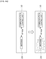
- FIGS. 1A and 1B are diagrams for describing problems of a communication apparatus for a vehicle of the related art.
- the communication apparatus for a vehicle of the related art may include a communication control unit 10 and an antenna 20.
- the communication control unit 10 may include a plurality of communication modems, and the plurality of communication modems may be connected to a plurality of antennas 20, which are provided according to a supported communication method, e.g., 5G, V2X, GPS, BT/WiFi, radio, DMB or the like, to establish communication.
- a supported communication method e.g., 5G, V2X, GPS, BT/WiFi, radio, DMB or the like, to establish communication.
- an antenna may be damaged due to an emergency such as an accident or damage to a vehicle. Even when there are undamaged antennas in the vehicle, the undamaged antennas may be unusable when there is no connection path. Even when there is a connection path for connection to an antenna that is not damaged, it is difficult to check whether the antenna is damaged or not and it is impossible to interwork with the antenna due to a different resonance point.
- Embodiments relate to a communication apparatus, for a vehicle, having a communication recovery function and a control method thereof.
- a communication apparatus for a vehicle may include an antenna unit including a first antenna and a plurality of second antennas, a first switch for switching between a first path to the first antenna and second paths to the plurality of second antennas, a second switch for switching the second path to one of the plurality of second antennas, a length adjustment unit connected to the second path to one second antenna connected to the second switch and configured to adjust a resonance length of the connected second antenna, and a communication control unit configured to generate a switching signal for connection to one of the plurality of second antennas according to a status of the first antenna.
- the length adjustment unit may include a plurality of circuits, and the plurality of circuits may include a bypass circuit configured to maintain the resonance length, a first adjustment circuit configured to reduce the resonance length, and a second adjustment circuit configured to increase the resonance length.
- the first adjustment circuit may include at least one capacitor, and the second adjustment circuit may include at least one inductor.
- the communication apparatus may further include a third switch connected between the second switch and the length adjustment unit and configured to switch one second antenna, which is connected to the second switch, to be connected to one of the plurality of circuits.
- the communication control unit may detect a level of a received signal by sequentially connecting each of the plurality of second antennas and each of the plurality of circuits, select a second antenna and a circuit corresponding to a highest level of the signal, and generate a switching signal for connecting the selected second antenna and the selected circuit.
- the second switch may select a second antenna among the plurality of second antennas, the third switch may be connected to one end of the selected circuit to be connected to the selected second antenna, and the first switch may be connected to the other end of the selected circuit.
- the communication control unit may detect a level of a signal received through the first antenna and check whether the first antenna is connected on the basis of the detected level of the signal, and control the first switch, the second switch, and the third switch to connect a second path to a second antenna selected from among the plurality of second antennas and one circuit, when the first antenna is not connected normally.
- the communication control unit may primarily check a status of the first antenna using the level of the signal received through the first antenna, secondarily check the status of the first antenna according to whether the first antenna is connected, and determine the status of the first antenna according to results of the primary checking and the secondary checking.
- a control method of a communication apparatus for a vehicle includes: when communication is established by connecting to a first antenna, determining a status of the first antenna; when the first antenna does not operate normally, sequentially connecting one second antenna from among the plurality of second antennas and one of a plurality of circuits for adjusting a resonance length of the one second antenna; and establishing communication by detecting a level of a signal received through the connected second antenna, selecting a second antenna from among the plurality of second antennas on the basis of the detected level of the signal, and connecting to the selected second antenna.
- the determining of the status of the first antenna may include primarily checking the status of the first antenna using a level of a signal received through the first antenna, secondarily checking the status of the first antenna according to whether the first antenna is connected, and determining the status of the first antenna according to results of the primary checking and the secondary checking.
- the establishing of communication may include detecting a level of a received signal by sequentially connecting each of the plurality of second antennas and one of the plurality of circuits, selecting a second antenna and a circuit corresponding to a highest level of the signal, and connecting the selected second antenna and circuit.
- any one of a plurality of second antennas can be selectively connected to according to predetermined priority and a resonance length of the selectively connected second antenna can be adjusted to a predetermined resonance length, and therefore, when an antenna is damaged due to an emergency, urgent communication recovery can be performed using another antenna.
- urgent communication recovery can be done using a plurality of antennas provided in a vehicle, thereby minimizing costs due to additional hardware configuration.
- Embodiments suggest a new method of selectively connecting to one of a plurality of second antennas according to predetermined priority when a first antenna does not operate normally, and adjusting a resonance length of the selectively connected second antenna to a predetermined resonance length.
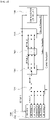
- FIG. 2 is a diagram illustrating a configuration of a communication apparatus for a vehicle according to an embodiment of the present disclosure.
- a communication apparatus for a vehicle may include a communication control unit 100, an antenna unit 200, a first switch 310, a second switch 320, a third switch 330, and a length adjustment unit 340.
- the communication control unit 100 may periodically determine a status of a first antenna and connect to a second antenna according to a result of the determination.
- the communication control unit 100 may be connected to the first antenna through a first path RF path_1 when the first antenna operates normally, and may be connected to the second antenna through a second path RF Path_2 by controlling the first switch 310, the second switch 320, and the third switch 330, when the first antenna does not operate normally.
- the communication control unit 100 may control a path by generating a switching signal for switching each of the first switch 310, the second switch 320, and the third switch 330.
- the communication control unit 100 may determine a status of the first antenna by detecting a level of a signal received through the first antenna, primarily checking the status of the first antenna on the basis of the detected level of the signal, and secondarily checking the status of first antenna on the basis of whether the first antenna is connected.
- the communication control unit 100 may check whether the first antenna is connected by checking whether a first path to the first antenna is open using an internal circuit.
- the status of the first antenna is determined through primary checking and secondary checking to prevent switching to the second antenna when a signal level is low in a weak electric field area even when the first antenna operates normally.
- the antenna unit 200 may include a first antenna 210 and a plurality of second antennas 220.
- the first antenna may be an antenna_1 for 4G/5G
- the second antennas may be an antenna_2 for V2X, an antenna_3 for GPS, an antenna_4 for BT/WiFi, an antenna_5 for Radio, and an antenna_6 for DMB.
- the first switch 310 may switch between the first path to the first antenna 210 and second paths to the plurality of second antennas 220.
- the first switch 310 may be, for example, a single-pole multi-throw (SPXT) switch.
- SPXT single-pole multi-throw
- the first switch 310 may generate a default path by maintaining a state in which the communication control unit 100 is connected to the first antenna 210.
- the default path is generated to prevent insertion loss in a switch and a path. That is, when an insertion loss rate is excessive, a transmission power level may increase, thus resulting in a decrease in communication quality due to lowering of linear performance.
- the first switch 310 may switch to the second paths to the plurality of second antennas 220, and particularly, a second path to one of the plurality of second antennas 220.
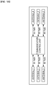
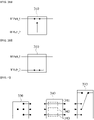
- FIGS. 3A and 3B are diagrams for describing a configuration principle of a first switch such as that shown in FIG. 2 .
- a first switch 310 when a first switch 310 according to an embodiment is designed to be positioned on a first path RF path_1, the first path RF Path_1 to a first antenna may be completely blocked.
- the first switch 310 when the first switch 310 is designed to be positioned on a second path RF Path 2, the first path RF Path_1 to the first antenna may not be completely blocked and thus a stub and an impedance mismatch may occur, thereby causing a signal loss.
- the first switch 310 is designed to have a structure as shown in FIG. 3A .
- the second switch 320 may switch to a second path of one of a plurality of second antennas.
- the second switch 320 may be, for example, an SPTX or multi-pole multi-throw (XPXT) switch. In this case, when the second switch 320 is used as the XPXT switch rather than the SPXT switch, two or more antennas are used.
- the third switch 330 may be switched to one circuit in the length adjustment unit 340 to adjust a resonance length of a connected second antenna.
- the third switch 330 may be an SPXT switch.
- the length adjustment unit 340 may adjust the resonance length of the second antenna to a predetermined resonance length. Because a resonance point of each antenna is different, a resonance length should be adjusted.
- FIG. 4 is a diagram illustrating a detailed configuration of the length adjustment unit 340 shown in FIG. 2 .
- the length adjustment unit 340 may include a plurality of circuits, and the plurality of circuits may include a first circuit 341, a second circuit 342, and a third circuit 343.
- the first circuit 341 may maintain a resonance length of an antenna without adjusting the resonance length.
- the second circuit 342 may reduce a resonance length of an antenna.
- the second circuit 342 may be implemented as, for example, at least one capacitor to reduce a resonance length of an antenna.
- the third circuit 343 may increase a resonance length of an antenna.
- the third circuit 343 may be implemented as, for example, at least one inductor to increase a resonance length of an antenna.
- an adjustment circuit is configured with a capacitor and an inductor is described but the types, the number, etc. of elements constituting the adjustment circuit may be implemented differently.
- the first circuit 341, the second circuit 342, and the third circuit 343 in the length adjustment unit 340 may be selected using the first switch 310 and the third switch 330.
- the second circuit 342 may be selected by switching the first switch 310 to be connected to one end of the second circuit 342 and switching the third switch 330 to be connected to the other end of the second circuit 342.
- the first switch 310 and the third switch 330 may be switched with the same circuit.
- paths each corresponding to one of second antenna candidates may be included in a length adjustment unit.
- Each of the paths may include elements having characteristic values for impedance matching of the second antenna candidate corresponding thereto. For example, when an antenna is selected as a second antenna by the second switch, a specific path for impedance matching of the antenna may be switched to, thereby forming a path to the first switch.
- FIG. 5 is a diagram illustrating a connected state of a first antenna according to an embodiment of the present disclosure
- FIG. 6 is a diagram illustrating a connected state of a second antenna according to an embodiment of the present disclosure.
- FIG. 5 illustrates an example in which a communication control unit 100 according to an embodiment is connected to a first antenna 210.
- the communication control unit 100 may be connected to the first antenna 210 and establish communication through the first antenna 210 connected thereto while a first switch 310 is connected to a first path.
- the communication control unit 100 is connected to a second antenna antenna_2 among second antennas 220, when the first antenna 210 is damaged due to an accident of a vehicle and thus does not operate normally.
- the communication control unit 100 may be connected to the second antenna 220 and establish communication through the second antenna 220 connected thereto while a second switch 320 is connected to a second path.
- the communication control unit 100 may detect a signal level by sequentially connecting all second paths to which the plurality of second antennas 200 are connectable in a predetermined order.
- each of the second paths to the plurality of second antennas 220 may be divided into three sub-paths according to whether a resonance length is adjusted or not.
- the communication control unit 100 may detect signal levels corresponding to a total of nine paths, because there are three paths for each of the three second antennas.
- the communication control unit 100 may compare the detected signal levels with one another and select a second antenna connected to the second path with a highest signal level according to a result of the comparison.
- the communication control unit 100 may generate a first switching signal, a second switching signal, and a third switching signal for respectively controlling the first switch 310, the second switch 320, a third switch 330, and supply the first switching signal, the second switching signal, and the third switching signal to the first switch 310, the second switch 320, and the third switch 330, respectively.
- the communication control unit 100 may switch the second switch 320 according to the second switching signal to be connected to the second antenna antenna_2 among the second antennas 220, switch the third switch 330 according to the third switching signal to be connected to one end of the second circuit, and switch the first switch 310 according to the first switching signal to be connected to the other end of the second circuit, thereby connecting to the second antenna antenna_2.
- FIG. 7 is a diagram illustrating a control method of a communication apparatus according to an embodiment of the present disclosure.
- a communication apparatus for a vehicle may be connected to a first antenna by default (S701) and transmit or receive signals through the first antenna.
- the communication apparatus for a vehicle may detect a level of the received signal (S703).
- the level of the signal may be a received signal strength indicator (RSSI) level.
- the communication apparatus for a vehicle may primarily check whether the detected level of the signal is greater than or equal to a predetermined threshold (S704).
- a predetermined threshold S704
- the threshold may be used as a reference value for the communication apparatus for a vehicle to detect whether an antenna is damaged.
- the communication apparatus for a vehicle may secondarily check whether the first antenna is connected (S705). Whether the first antenna is connected indicates whether a first path is open or closed.
- the communication apparatus for a vehicle may connect to one of a plurality of second antennas when a result of the secondary checking reveals that the first antenna does not operate normally (S706).
- the communication apparatus for a vehicle establishes communication through the connected second antenna (S707).
- the communication apparatus for a vehicle may establish emergency communication through the second antenna.
- FIG. 8 is a diagram for describing a first connection process of connecting to a second antenna shown in FIG. 7 .
- a communication apparatus for a vehicle may connect an m th path to an n th second antenna, i.e., a second antenna_ ⁇ n, m ⁇ , among second antennas corresponding to predetermined antennas and circuits ⁇ N, M ⁇ (S801).
- a path to the n th second antenna may be divided into m paths according to whether a resonance length is adjusted or not.
- the communication apparatus for a vehicle may detect a level of the received signal (S803).
- the level of the signal may be an RSSI level.
- the communication apparatus for a vehicle may store the detected level of the signal from the m th path to the n th second antenna (S804).
- the communication apparatus for a vehicle may change the antenna sequence to n+1 (S808), and an iteration of connecting to an m th path to an (n+1) th second antenna may be performed.
- the communication apparatus for a vehicle may select the m th path to the n th second antenna with a highest signal level on the basis of the stored level of the signal (S809).
- the communication apparatus for a vehicle may connect the m th path to the n th second antenna (S810).
- first, antennas with high signal levels, which are to be connected to, may be identified using a predetermined threshold and one of these antennas may be selected. In this case, two or more thresholds may be determined.
- FIG. 9 is a diagram for describing a second connection process of connecting to the second antenna shown in FIG. 7 .
- a communication apparatus for a vehicle may connect an m th path to an n th second antenna, i.e., a second antenna_ ⁇ n, m ⁇ , among second antennas corresponding to predetermined antennas and circuits ⁇ N, M ⁇ (S901).
- the communication apparatus for a vehicle may detect a level of the received signal (S903).
- the communication apparatus for a vehicle may check whether the detected level of the signal is greater than or equal to a predetermined threshold (S904).
- the communication apparatus for a vehicle may store the detected level of the signal from the m th path to the n th second antenna (S905).
- the communication apparatus for a vehicle may change the antenna sequence to n+1 (S909), and an iteration of connecting to an m th path to an (n+1) th second antenna may be performed.
- the communication apparatus for a vehicle may select the m th path to the n th second antenna with a highest signal level on the basis of the stored level of the signal (S910).
- the communication apparatus for a vehicle may connect the m th path to the n th second antenna (S911).
- an antenna with a high signal level among a plurality of second antennas may be selected.
- unit used in the embodiments set forth herein should be understood to mean a software or hardware component, such as a field-programmable gate array (FPGA) or an application-specific integrated circuit (ASIC), which performs certain functions.
- FPGA field-programmable gate array
- ASIC application-specific integrated circuit
- the term “unit” is not limited to software or hardware.
- the term “unit” may be configured to be stored in an addressable storage medium or to execute one or more processors.
- the term “unit” may include, for example, components, such as software components, object-oriented software components, class components, and task components, processes, functions, attributes, procedures, subroutines, segments of program code, drivers, firmware, microcode, circuits, data, databases, data structures, tables, arrays, and parameters.
- components and functions provided in “units” may be combined into a smaller number of components and “units” or may be divided into subcomponents and “sub-units”.
- the components and “units” may be implemented to execute one or more CPUs in a device or a secure multimedia card.
Landscapes
- Engineering & Computer Science (AREA)
- Computer Networks & Wireless Communication (AREA)
- Signal Processing (AREA)
- Remote Sensing (AREA)
- Transceivers (AREA)
- Input Circuits Of Receivers And Coupling Of Receivers And Audio Equipment (AREA)
- Variable-Direction Aerials And Aerial Arrays (AREA)
- Transmitters (AREA)
Abstract
Description
- Embodiments relate to a communication apparatus for a vehicle and a control method thereof.
- An antenna is a device used to efficiently emit radio waves to a space for wireless communication. In particular, the importance of antennas is increasing as usage of wireless communication is increasing exponentially, compared to that of wired communication.
- A car includes not only mechanical components but also a large number of electronic components and thus an antenna is essentially included in the car.
-
FIGS. 1A and1B are diagrams for describing problems of a communication apparatus for a vehicle of the related art. - Referring to
FIGS. 1A to 1B , the communication apparatus for a vehicle of the related art may include acommunication control unit 10 and anantenna 20. Thecommunication control unit 10 may include a plurality of communication modems, and the plurality of communication modems may be connected to a plurality ofantennas 20, which are provided according to a supported communication method, e.g., 5G, V2X, GPS, BT/WiFi, radio, DMB or the like, to establish communication. - In this case, an antenna may be damaged due to an emergency such as an accident or damage to a vehicle. Even when there are undamaged antennas in the vehicle, the undamaged antennas may be unusable when there is no connection path. Even when there is a connection path for connection to an antenna that is not damaged, it is difficult to check whether the antenna is damaged or not and it is impossible to interwork with the antenna due to a different resonance point.
-
- (Patent Document 1)
Korean Patent Laid-Open Publication No. 10-2018-0027944 - (Patent Document 2)
Korean Patent Laid-Open Publication No. 10-2016-0091891 - Embodiments relate to a communication apparatus, for a vehicle, having a communication recovery function and a control method thereof.
- A communication apparatus for a vehicle according to an embodiment may include an antenna unit including a first antenna and a plurality of second antennas, a first switch for switching between a first path to the first antenna and second paths to the plurality of second antennas, a second switch for switching the second path to one of the plurality of second antennas, a length adjustment unit connected to the second path to one second antenna connected to the second switch and configured to adjust a resonance length of the connected second antenna, and a communication control unit configured to generate a switching signal for connection to one of the plurality of second antennas according to a status of the first antenna.
- The length adjustment unit may include a plurality of circuits, and the plurality of circuits may include a bypass circuit configured to maintain the resonance length, a first adjustment circuit configured to reduce the resonance length, and a second adjustment circuit configured to increase the resonance length.
- The first adjustment circuit may include at least one capacitor, and the second adjustment circuit may include at least one inductor.
- The communication apparatus may further include a third switch connected between the second switch and the length adjustment unit and configured to switch one second antenna, which is connected to the second switch, to be connected to one of the plurality of circuits.
- The communication control unit may detect a level of a received signal by sequentially connecting each of the plurality of second antennas and each of the plurality of circuits, select a second antenna and a circuit corresponding to a highest level of the signal, and generate a switching signal for connecting the selected second antenna and the selected circuit.
- The second switch may select a second antenna among the plurality of second antennas, the third switch may be connected to one end of the selected circuit to be connected to the selected second antenna, and the first switch may be connected to the other end of the selected circuit.
- The communication control unit may detect a level of a signal received through the first antenna and check whether the first antenna is connected on the basis of the detected level of the signal, and control the first switch, the second switch, and the third switch to connect a second path to a second antenna selected from among the plurality of second antennas and one circuit, when the first antenna is not connected normally.
- The communication control unit may primarily check a status of the first antenna using the level of the signal received through the first antenna, secondarily check the status of the first antenna according to whether the first antenna is connected, and determine the status of the first antenna according to results of the primary checking and the secondary checking.
- A control method of a communication apparatus for a vehicle according to an embodiment includes: when communication is established by connecting to a first antenna, determining a status of the first antenna; when the first antenna does not operate normally, sequentially connecting one second antenna from among the plurality of second antennas and one of a plurality of circuits for adjusting a resonance length of the one second antenna; and establishing communication by detecting a level of a signal received through the connected second antenna, selecting a second antenna from among the plurality of second antennas on the basis of the detected level of the signal, and connecting to the selected second antenna.
- The determining of the status of the first antenna may include primarily checking the status of the first antenna using a level of a signal received through the first antenna, secondarily checking the status of the first antenna according to whether the first antenna is connected, and determining the status of the first antenna according to results of the primary checking and the secondary checking.
- The establishing of communication may include detecting a level of a received signal by sequentially connecting each of the plurality of second antennas and one of the plurality of circuits, selecting a second antenna and a circuit corresponding to a highest level of the signal, and connecting the selected second antenna and circuit.
- According to embodiments, when a first antenna does not operate normally, any one of a plurality of second antennas can be selectively connected to according to predetermined priority and a resonance length of the selectively connected second antenna can be adjusted to a predetermined resonance length, and therefore, when an antenna is damaged due to an emergency, urgent communication recovery can be performed using another antenna.
- According to embodiments, it is possible to determine a situation in which the first antenna does not operate normally and thus pre-recovery can be done before operation of a vehicle.
- According to embodiments, urgent communication recovery can be done using a plurality of antennas provided in a vehicle, thereby minimizing costs due to additional hardware configuration.
-
-
FIGS. 1A and1B are diagrams for describing problems of a communication apparatus for a vehicle of the related art. -
FIG. 2 is a diagram illustrating a configuration of a communication apparatus for a vehicle according to an embodiment of the present disclosure. -
FIGS. 3A and 3B are diagrams for describing a configuration principle of a first switch shown inFIG. 2 . -
FIG. 4 is a diagram illustrating a detailed configuration of a length adjustment unit shown inFIG. 2 . -
FIG. 5 is a diagram illustrating a connected state of a first antenna according to an embodiment of the present disclosure. -
FIG. 6 is a diagram illustrating a connected state of a second antenna according to an embodiment of the present disclosure. -
FIG. 7 is a diagram illustrating a control method of a communication apparatus according to an embodiment of the present disclosure. -
FIG. 8 is a diagram for describing a first connection process of connecting to a second antenna shown inFIG. 7 . -
FIG. 9 is a diagram for describing a second connection process of connecting to the second antenna shown inFIG. 7 . - Hereinafter, embodiments of the present disclosure will be described in detail with reference to the accompanying drawings.
- However, the technical idea of the present disclosure is not limited to the embodiments set forth herein and may be implemented in many different forms and one or more components between embodiments may be selectively combined or replaced with other components without departing from the scope of the present disclosure.
- Unless otherwise defined, all terms (including technical and scientific terms) used in the embodiments of the present disclosure have the same meaning as commonly understood by one of ordinary skill in the art to which the present disclosure belongs. It will be understood that terms, such as those defined in commonly used dictionaries, should be interpreted as having a meaning that is consistent with their meaning in the context of the relevant art.
- Terms used in the embodiments of the present disclosure are for the purpose of only describing the embodiments and are not intended to be limiting of the present disclosure.
- As used herein, singular forms are intended to include plural forms as well, unless the context clearly indicates otherwise. It will be understood that "at least one of (or at least one or more of) A, B, and C" indicates one or more of all possible combinations of A, B, and C.
- Terms such as first, second, A, B, (a), and (b) may be used to describe components of embodiment of the present disclosure.
- Such a term is only for distinguishing one component from another, and the essence of the component, an order or a sequence is not limited by the term.
- When a component is referred to as being "coupled to" or "connected to" another component, it will be understood that the component is directly coupled to or connected to the other component or is coupled to or connected to the other component through another component interposed therebetween.
- When one of components are referred to as being formed or disposed "on (or above)" or "below (or under)" the other, it will be understood that the components are in direct contact with each other or one or more components are formed or disposed therebetween. The expression "on (or above)" or "below (or under)" should be understood to include not only an upward direction but also a downward direction with respect to one component.
- Embodiments suggest a new method of selectively connecting to one of a plurality of second antennas according to predetermined priority when a first antenna does not operate normally, and adjusting a resonance length of the selectively connected second antenna to a predetermined resonance length.
-
FIG. 2 is a diagram illustrating a configuration of a communication apparatus for a vehicle according to an embodiment of the present disclosure. - Referring to
FIG. 2 , a communication apparatus for a vehicle according to an embodiment of the present disclosure may include acommunication control unit 100, anantenna unit 200, afirst switch 310, asecond switch 320, athird switch 330, and alength adjustment unit 340. - The
communication control unit 100 may periodically determine a status of a first antenna and connect to a second antenna according to a result of the determination. Thecommunication control unit 100 may be connected to the first antenna through a first path RF path_1 when the first antenna operates normally, and may be connected to the second antenna through a second path RF Path_2 by controlling thefirst switch 310, thesecond switch 320, and thethird switch 330, when the first antenna does not operate normally. - The
communication control unit 100 may control a path by generating a switching signal for switching each of thefirst switch 310, thesecond switch 320, and thethird switch 330. - The
communication control unit 100 may determine a status of the first antenna by detecting a level of a signal received through the first antenna, primarily checking the status of the first antenna on the basis of the detected level of the signal, and secondarily checking the status of first antenna on the basis of whether the first antenna is connected. - In this case, the
communication control unit 100 may check whether the first antenna is connected by checking whether a first path to the first antenna is open using an internal circuit. - In an embodiment, the status of the first antenna is determined through primary checking and secondary checking to prevent switching to the second antenna when a signal level is low in a weak electric field area even when the first antenna operates normally.
- The
antenna unit 200 may include afirst antenna 210 and a plurality ofsecond antennas 220. For example, the first antenna may be an antenna_1 for 4G/5G, and the second antennas may be an antenna_2 for V2X, an antenna_3 for GPS, an antenna_4 for BT/WiFi, an antenna_5 for Radio, and an antenna_6 for DMB. - The
first switch 310 may switch between the first path to thefirst antenna 210 and second paths to the plurality ofsecond antennas 220. Here, thefirst switch 310 may be, for example, a single-pole multi-throw (SPXT) switch. Thefirst switch 310 may generate a default path by maintaining a state in which thecommunication control unit 100 is connected to thefirst antenna 210. - The default path is generated to prevent insertion loss in a switch and a path. That is, when an insertion loss rate is excessive, a transmission power level may increase, thus resulting in a decrease in communication quality due to lowering of linear performance.
- The
first switch 310 may switch to the second paths to the plurality ofsecond antennas 220, and particularly, a second path to one of the plurality ofsecond antennas 220. -
FIGS. 3A and 3B are diagrams for describing a configuration principle of a first switch such as that shown inFIG. 2 . - Referring to
FIG. 3A , when afirst switch 310 according to an embodiment is designed to be positioned on a first path RF path_1, the first path RF Path_1 to a first antenna may be completely blocked. - Referring to
FIG. 3B , when thefirst switch 310 is designed to be positioned on a secondpath RF Path 2, the first path RF Path_1 to the first antenna may not be completely blocked and thus a stub and an impedance mismatch may occur, thereby causing a signal loss. - Therefore, in an embodiment, the
first switch 310 is designed to have a structure as shown inFIG. 3A . - The
second switch 320 may switch to a second path of one of a plurality of second antennas. Thesecond switch 320 may be, for example, an SPTX or multi-pole multi-throw (XPXT) switch. In this case, when thesecond switch 320 is used as the XPXT switch rather than the SPXT switch, two or more antennas are used. - The
third switch 330 may be switched to one circuit in thelength adjustment unit 340 to adjust a resonance length of a connected second antenna. Thethird switch 330 may be an SPXT switch. - The
length adjustment unit 340 may adjust the resonance length of the second antenna to a predetermined resonance length. Because a resonance point of each antenna is different, a resonance length should be adjusted. -
FIG. 4 is a diagram illustrating a detailed configuration of thelength adjustment unit 340 shown inFIG. 2 . - Referring to
FIG. 4 , thelength adjustment unit 340 according to an embodiment may include a plurality of circuits, and the plurality of circuits may include afirst circuit 341, asecond circuit 342, and athird circuit 343. - The
first circuit 341 may maintain a resonance length of an antenna without adjusting the resonance length. - The
second circuit 342 may reduce a resonance length of an antenna. Thesecond circuit 342 may be implemented as, for example, at least one capacitor to reduce a resonance length of an antenna. - The third circuit 343may increase a resonance length of an antenna. The
third circuit 343 may be implemented as, for example, at least one inductor to increase a resonance length of an antenna. - Here, an example in which an adjustment circuit is configured with a capacitor and an inductor is described but the types, the number, etc. of elements constituting the adjustment circuit may be implemented differently.
- In this case, the
first circuit 341, thesecond circuit 342, and thethird circuit 343 in thelength adjustment unit 340 may be selected using thefirst switch 310 and thethird switch 330. For example, thesecond circuit 342 may be selected by switching thefirst switch 310 to be connected to one end of thesecond circuit 342 and switching thethird switch 330 to be connected to the other end of thesecond circuit 342. - Therefore, the
first switch 310 and thethird switch 330 may be switched with the same circuit. - As another example, paths each corresponding to one of second antenna candidates may be included in a length adjustment unit. Each of the paths may include elements having characteristic values for impedance matching of the second antenna candidate corresponding thereto. For example, when an antenna is selected as a second antenna by the second switch, a specific path for impedance matching of the antenna may be switched to, thereby forming a path to the first switch.
-
FIG. 5 is a diagram illustrating a connected state of a first antenna according to an embodiment of the present disclosure, andFIG. 6 is a diagram illustrating a connected state of a second antenna according to an embodiment of the present disclosure. -
FIG. 5 illustrates an example in which acommunication control unit 100 according to an embodiment is connected to afirst antenna 210. Thecommunication control unit 100 may be connected to thefirst antenna 210 and establish communication through thefirst antenna 210 connected thereto while afirst switch 310 is connected to a first path. - Referring to
FIG. 6 , thecommunication control unit 100 according to the embodiment is connected to a second antenna antenna_2 amongsecond antennas 220, when thefirst antenna 210 is damaged due to an accident of a vehicle and thus does not operate normally. Thecommunication control unit 100 may be connected to thesecond antenna 220 and establish communication through thesecond antenna 220 connected thereto while asecond switch 320 is connected to a second path. - When the
first antenna 210 does not operate normally, thecommunication control unit 100 may detect a signal level by sequentially connecting all second paths to which the plurality ofsecond antennas 200 are connectable in a predetermined order. In this case, each of the second paths to the plurality ofsecond antennas 220 may be divided into three sub-paths according to whether a resonance length is adjusted or not. - For example, when there are three second antennas, the
communication control unit 100 may detect signal levels corresponding to a total of nine paths, because there are three paths for each of the three second antennas. - The
communication control unit 100 may compare the detected signal levels with one another and select a second antenna connected to the second path with a highest signal level according to a result of the comparison. - When the second antenna is selected, the
communication control unit 100 may generate a first switching signal, a second switching signal, and a third switching signal for respectively controlling thefirst switch 310, thesecond switch 320, athird switch 330, and supply the first switching signal, the second switching signal, and the third switching signal to thefirst switch 310, thesecond switch 320, and thethird switch 330, respectively. - For example, when a second antenna connected to a second circuit for reducing a resonance length is selected, the
communication control unit 100 may switch thesecond switch 320 according to the second switching signal to be connected to the second antenna antenna_2 among thesecond antennas 220, switch thethird switch 330 according to the third switching signal to be connected to one end of the second circuit, and switch thefirst switch 310 according to the first switching signal to be connected to the other end of the second circuit, thereby connecting to the second antenna antenna_2. -
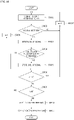
FIG. 7 is a diagram illustrating a control method of a communication apparatus according to an embodiment of the present disclosure. - Referring to
FIG. 7 , a communication apparatus for a vehicle according to an embodiment of the present disclosure may be connected to a first antenna by default (S701) and transmit or receive signals through the first antenna. - When receiving a signal through the first antenna (S702), the communication apparatus for a vehicle may detect a level of the received signal (S703). Here, the level of the signal may be a received signal strength indicator (RSSI) level.
- The communication apparatus for a vehicle may primarily check whether the detected level of the signal is greater than or equal to a predetermined threshold (S704). Here, when the detected level of the signal is less than the threshold, it may mean that the communication apparatus is located in a weak electric field area. Alternatively, the threshold may be used as a reference value for the communication apparatus for a vehicle to detect whether an antenna is damaged.
- When the detected level of the signal is less than the threshold, the communication apparatus for a vehicle may secondarily check whether the first antenna is connected (S705). Whether the first antenna is connected indicates whether a first path is open or closed.
- The communication apparatus for a vehicle may connect to one of a plurality of second antennas when a result of the secondary checking reveals that the first antenna does not operate normally (S706).
- The communication apparatus for a vehicle establishes communication through the connected second antenna (S707). For example, the communication apparatus for a vehicle may establish emergency communication through the second antenna.
-
FIG. 8 is a diagram for describing a first connection process of connecting to a second antenna shown inFIG. 7 . - Referring to
FIG. 8 , when a first antenna does not operate normally, a communication apparatus for a vehicle according to an embodiment of the present disclosure may connect an mth path to an nth second antenna, i.e., a second antenna_{n, m}, among second antennas corresponding to predetermined antennas and circuits {N, M} (S801). - In this case, a path to the nth second antenna may be divided into m paths according to whether a resonance length is adjusted or not.
- When receiving a signal through the mth path to the nth second antenna connected (S802), the communication apparatus for a vehicle may detect a level of the received signal (S803). Here, the level of the signal may be an RSSI level.
- The communication apparatus for a vehicle may store the detected level of the signal from the mth path to the nth second antenna (S804).
- The communication apparatus for a vehicle may check whether m=M is satisfied (S805), and when m= M is not satisfied, a path sequence is changed to m+1 (S806). Thereafter, an iteration of connecting to an (m+1)th path to the nth second antenna may be performed.
- On the other hand, when m=M is satisfied, the communication apparatus for a vehicle may determine that checking of all paths to the nth second antenna is completed and check whether n=N is satisfied (S807).
- When n=N is not satisfied, the communication apparatus for a vehicle may change the antenna sequence to n+1 (S808), and an iteration of connecting to an mth path to an (n+1)th second antenna may be performed.
- On the other hand, when n=N is satisfied, the communication apparatus for a vehicle may select the mth path to the nth second antenna with a highest signal level on the basis of the stored level of the signal (S809).
- The communication apparatus for a vehicle may connect the mth path to the nth second antenna (S810).
- In an embodiment, first, antennas with high signal levels, which are to be connected to, may be identified using a predetermined threshold and one of these antennas may be selected. In this case, two or more thresholds may be determined.
-
FIG. 9 is a diagram for describing a second connection process of connecting to the second antenna shown inFIG. 7 . - Referring to
FIG. 9 , when a first antenna does not operate normally, a communication apparatus for a vehicle according to an embodiment of the present disclosure may connect an mth path to an nth second antenna, i.e., a second antenna_{n, m}, among second antennas corresponding to predetermined antennas and circuits {N, M} (S901). - When receiving a signal through the mth path to the nth second antenna (S902), the communication apparatus for a vehicle may detect a level of the received signal (S903).
- The communication apparatus for a vehicle may check whether the detected level of the signal is greater than or equal to a predetermined threshold (S904).
- When the detected level of the signal is greater than or equal to the threshold, the communication apparatus for a vehicle may store the detected level of the signal from the mth path to the nth second antenna (S905).
- The communication apparatus for a vehicle may check whether m=M is satisfied (S906), and when m= M is not satisfied, a path sequence is changed to m+1 (S907). Thereafter, an iteration of connecting to an (m+1)th path to the nth second antenna may be performed.
- On the other hand, when m=M is satisfied, the communication apparatus for a vehicle may determine that checking of all paths to the nth second antenna is completed and check whether n=N is satisfied (S908).
- When n=N is not satisfied, the communication apparatus for a vehicle may change the antenna sequence to n+1 (S909), and an iteration of connecting to an mth path to an (n+1)th second antenna may be performed.
- On the other hand, when n=N is satisfied, the communication apparatus for a vehicle may select the mth path to the nth second antenna with a highest signal level on the basis of the stored level of the signal (S910).
- The communication apparatus for a vehicle may connect the mth path to the nth second antenna (S911).
- Therefore, in an embodiment, an antenna with a high signal level among a plurality of second antennas may be selected.
- The term "unit" used in the embodiments set forth herein should be understood to mean a software or hardware component, such as a field-programmable gate array (FPGA) or an application-specific integrated circuit (ASIC), which performs certain functions. However, the term "unit" is not limited to software or hardware. The term "unit" may be configured to be stored in an addressable storage medium or to execute one or more processors. Thus, the term "unit" may include, for example, components, such as software components, object-oriented software components, class components, and task components, processes, functions, attributes, procedures, subroutines, segments of program code, drivers, firmware, microcode, circuits, data, databases, data structures, tables, arrays, and parameters. Components and functions provided in "units" may be combined into a smaller number of components and "units" or may be divided into subcomponents and "sub-units". In addition, the components and "units" may be implemented to execute one or more CPUs in a device or a secure multimedia card.
- While the present disclosure has been described above with reference to exemplary embodiments thereof, it should be understood by those of ordinary skill in the art that various changes and modifications may be made without departing from the technical spirit and scope of the present disclosure defined in the following claims.
-
- 100: communication control unit
- 200: antenna unit
- 210: first antenna
- 220: second antenna
- 310: first switch
- 320: second switch
- 330: third switch
- 340: length adjustment unit
Claims (11)
- A communication apparatus for a vehicle, comprising:an antenna unit including a first antenna and a plurality of second antennas;a first switch configured to switch between a first path to the first antenna and second paths to the plurality of second antennas;a second switch configured to switch the second path to one of the plurality of second antennas;a length adjustment unit connected to the second path to a second antenna connected to the second switch, and configured to adjust a resonance length of the connected second antenna; anda communication control unit configured to generate a switching signal for connecting to a second antenna among the plurality of second antennas according to a status of the first antenna.
- The communication apparatus of claim 1, wherein the length adjustment unit comprises a plurality of circuits,
wherein the plurality of circuits comprise:a first circuit configured to maintain the resonance length;a second circuit configured to reduce the resonance length; anda third circuit configured to increase the resonance length. - The communication apparatus of claim 2, wherein the second circuit comprises at least one capacitor, and
the third circuit comprises at least one inductor. - The communication apparatus of claim 2, further comprising a third switch connected between the second switch and the length adjustment unit, and configured to switch one second antenna, which is connected to the second switch, to be connected to any one of the plurality of circuits constituting the length adjustment unit.
- The communication apparatus of claim 4, wherein the communication control unit detects a level of a received signal by sequentially connecting each of the plurality of second antennas and each of the plurality of circuits, selects a second antenna and a circuit corresponding to a highest level of the signal, and generates a switching signal for connecting the selected second antenna and the selected circuit.
- The communication apparatus of claim 5, wherein the second switch selects a second antenna among the plurality of second antennas,the third switch is connected to one end of the selected circuit to be connected to the selected second antenna, andthe first switch is connected to the other end of the selected circuit.
- The communication apparatus of claim 5, wherein the communication control unit detects a level of a signal received through the first antenna and checks whether the first antenna is connected on the basis of the detected level of the signal, and controls the first switch, the second switch, and the third switch to connect a second path to a second antenna selected from among the plurality of second antennas and one circuit, when the first antenna is not connected normally.
- The communication apparatus of claim 1, wherein the communication control unit primarily checks a status of the first antenna using a level of a signal received through the first antenna, secondarily checks the status of the first antenna according to whether the first antenna is connected, and determines the status of the first antenna according to results of the primary checking and the secondary checking.
- A control method of a communication apparatus for a vehicle, comprising:when communication is established by connecting to a first antenna, determining a status of the first antenna;when the first antenna does not operate normally, sequentially connecting one second antenna from among the plurality of second antennas and one of a plurality of circuits for adjusting a resonance length of the one second antenna; andestablishing communication by detecting a level of a signal received through the connected second antenna, selecting a second antenna from among the plurality of second antennas on the basis of the detected level of the signal, and connecting to the selected second antenna.
- The control method of claim 9, wherein the determining of the status of the first antenna comprises:primarily checking the status of the first antenna using a level of a signal received through the first antenna;secondarily checking the status of the first antenna according to whether the first antenna is connected; anddetermining the status of the first antenna according to results of the primary checking and the secondary checking.
- The control method of claim 9, wherein, the establishing of communication comprises:detecting a level of a received signal by sequentially connecting each of the plurality of second antennas and each of the plurality of circuits;selecting a second antenna and a circuit corresponding to a highest level of the signal; andconnecting the selected second antenna and circuit.
Applications Claiming Priority (2)
| Application Number | Priority Date | Filing Date | Title |
|---|---|---|---|
| KR1020200000444A KR20210087326A (en) | 2020-01-02 | 2020-01-02 | Communication device for vehicle and method for controlling of the same |
| PCT/KR2020/019469 WO2021137649A1 (en) | 2020-01-02 | 2020-12-31 | Communication apparatus for vehicle and control method therefor |
Publications (2)
| Publication Number | Publication Date |
|---|---|
| EP4087054A1 true EP4087054A1 (en) | 2022-11-09 |
| EP4087054A4 EP4087054A4 (en) | 2023-03-29 |
Family
ID=76686708
Family Applications (1)
| Application Number | Title | Priority Date | Filing Date |
|---|---|---|---|
| EP20909090.1A Pending EP4087054A4 (en) | 2020-01-02 | 2020-12-31 | VEHICLE COMMUNICATION APPARATUS AND CONTROL METHOD THEREOF |
Country Status (6)
| Country | Link |
|---|---|
| US (1) | US12218433B2 (en) |
| EP (1) | EP4087054A4 (en) |
| JP (1) | JP7752113B2 (en) |
| KR (1) | KR20210087326A (en) |
| CN (1) | CN114902489A (en) |
| WO (1) | WO2021137649A1 (en) |
Family Cites Families (12)
| Publication number | Priority date | Publication date | Assignee | Title |
|---|---|---|---|---|
| JPH10190516A (en) | 1996-12-25 | 1998-07-21 | Sharp Corp | Portable radio |
| KR100989064B1 (en) | 2006-10-26 | 2010-10-25 | 한국전자통신연구원 | Multiple resonant antenna |
| WO2009142000A1 (en) | 2008-05-22 | 2009-11-26 | パナソニック株式会社 | Mimo antenna device and wireless communication device |
| KR20110100015A (en) * | 2010-03-03 | 2011-09-09 | 삼성전자주식회사 | A terminal comprising a plurality of antennas and a method of operating the same |
| KR101778527B1 (en) | 2011-06-07 | 2017-09-26 | 삼성전자 주식회사 | Method and apparatus for switching of antenna in portable terminal |
| GB2502308B (en) | 2012-05-22 | 2014-09-17 | Toshiba Res Europ Ltd | A transceiver, system and method for selecting an antenna |
| DE102013224514A1 (en) | 2013-11-29 | 2015-06-03 | Bayerische Motoren Werke Aktiengesellschaft | Vehicle communication system and method of operating such a system |
| KR102516621B1 (en) * | 2016-04-08 | 2023-03-31 | 삼성전자주식회사 | Method for controlling antenna and electronic device thereof |
| KR20180027944A (en) | 2016-09-07 | 2018-03-15 | 엘지이노텍 주식회사 | Antenna switch apparatus |
| CN206134924U (en) * | 2016-11-10 | 2017-04-26 | 广州三星通信技术研究有限公司 | Electronic terminal apparatus |
| KR101745612B1 (en) | 2017-01-19 | 2017-06-12 | 주식회사 우과전자 | Multi-band antenna possible for shifting resonance frequency |
| CN209805817U (en) * | 2019-04-17 | 2019-12-17 | 深圳沸石科技股份有限公司 | Tuning circuit and mobile terminal |
-
2020
- 2020-01-02 KR KR1020200000444A patent/KR20210087326A/en active Pending
- 2020-12-31 US US17/758,368 patent/US12218433B2/en active Active
- 2020-12-31 CN CN202080091026.5A patent/CN114902489A/en active Pending
- 2020-12-31 WO PCT/KR2020/019469 patent/WO2021137649A1/en not_active Ceased
- 2020-12-31 JP JP2022534273A patent/JP7752113B2/en active Active
- 2020-12-31 EP EP20909090.1A patent/EP4087054A4/en active Pending
Also Published As
| Publication number | Publication date |
|---|---|
| JP2023509308A (en) | 2023-03-08 |
| US20230027539A1 (en) | 2023-01-26 |
| EP4087054A4 (en) | 2023-03-29 |
| US12218433B2 (en) | 2025-02-04 |
| KR20210087326A (en) | 2021-07-12 |
| JP7752113B2 (en) | 2025-10-09 |
| CN114902489A (en) | 2022-08-12 |
| WO2021137649A1 (en) | 2021-07-08 |
Similar Documents
| Publication | Publication Date | Title |
|---|---|---|
| US9031516B2 (en) | Apparatus and method for impedance adjustment | |
| JP2009165082A (en) | Portable radio | |
| US12336033B2 (en) | Device control method, computer-readable storage medium, and electronic device for dual Wi-Fi | |
| JP5657547B2 (en) | transceiver | |
| JPWO2006082613A1 (en) | RFID communication control method and RFID system using the same | |
| CN113015128B (en) | Communication system | |
| US20170346521A1 (en) | Electronic device with antenna control function and antenna control method | |
| EP4087054A1 (en) | Communication apparatus for vehicle and control method therefor | |
| CN103368620A (en) | Portable device | |
| EP3866350B1 (en) | Communication method and communication apparatus of vehicle | |
| CN112242854B (en) | Electronic equipment, and control method and device of electronic equipment | |
| CN111034248A (en) | Method and computing device for performing wireless communication with multiple nodes of a wireless network | |
| CN103164371A (en) | Data processing method, antenna supplying method and electronic devices | |
| JP4867419B2 (en) | Non-contact communication apparatus and method, and program | |
| CN113765533B (en) | Antenna detection method and device, electronic equipment and storage medium | |
| CN109714067A (en) | System frequency band switching method, device, storage medium, receiving end and terminal | |
| JP2002290298A (en) | Wireless receiver | |
| TWI812064B (en) | Radio frequency matching switch circuit and radio frequency matching switch method | |
| CN210665995U (en) | Radio frequency switch-based on-site detection circuit for RFID reader-writer antenna | |
| KR20230119666A (en) | Single Pole Double Throw Radio Frequency Switch Topology | |
| CN113507291B (en) | Signal processing method, device, computer equipment and storage medium | |
| CN105512065A (en) | Information processing method and electronic equipment | |
| US11688937B2 (en) | Antenna device | |
| JP4254401B2 (en) | Portable wireless terminal and antenna selection method thereof | |
| CN118118048A (en) | Radio frequency module, power supply control method, communication device, and readable storage medium |
Legal Events
| Date | Code | Title | Description |
|---|---|---|---|
| STAA | Information on the status of an ep patent application or granted ep patent |
Free format text: STATUS: THE INTERNATIONAL PUBLICATION HAS BEEN MADE |
|
| PUAI | Public reference made under article 153(3) epc to a published international application that has entered the european phase |
Free format text: ORIGINAL CODE: 0009012 |
|
| STAA | Information on the status of an ep patent application or granted ep patent |
Free format text: STATUS: REQUEST FOR EXAMINATION WAS MADE |
|
| 17P | Request for examination filed |
Effective date: 20220624 |
|
| AK | Designated contracting states |
Kind code of ref document: A1 Designated state(s): AL AT BE BG CH CY CZ DE DK EE ES FI FR GB GR HR HU IE IS IT LI LT LU LV MC MK MT NL NO PL PT RO RS SE SI SK SM TR |
|
| A4 | Supplementary search report drawn up and despatched |
Effective date: 20230224 |
|
| RIC1 | Information provided on ipc code assigned before grant |
Ipc: H04B 1/3822 20150101ALI20230220BHEP Ipc: H04B 1/04 20060101ALI20230220BHEP Ipc: H01Q 9/04 20060101ALI20230220BHEP Ipc: H01Q 1/32 20060101AFI20230220BHEP |
|
| DAV | Request for validation of the european patent (deleted) | ||
| DAX | Request for extension of the european patent (deleted) | ||
| STAA | Information on the status of an ep patent application or granted ep patent |
Free format text: STATUS: EXAMINATION IS IN PROGRESS |
|
| 17Q | First examination report despatched |
Effective date: 20251212 |