EP4086896A1 - Far-field sound support frame having lens function, and electrical apparatus - Google Patents
Far-field sound support frame having lens function, and electrical apparatus Download PDFInfo
- Publication number
- EP4086896A1 EP4086896A1 EP20909998.5A EP20909998A EP4086896A1 EP 4086896 A1 EP4086896 A1 EP 4086896A1 EP 20909998 A EP20909998 A EP 20909998A EP 4086896 A1 EP4086896 A1 EP 4086896A1
- Authority
- EP
- European Patent Office
- Prior art keywords
- far
- field speech
- support
- disposed
- lens function
- Prior art date
- Legal status (The legal status is an assumption and is not a legal conclusion. Google has not performed a legal analysis and makes no representation as to the accuracy of the status listed.)
- Granted
Links
Images


Classifications
-
- H—ELECTRICITY
- H04—ELECTRIC COMMUNICATION TECHNIQUE
- H04N—PICTORIAL COMMUNICATION, e.g. TELEVISION
- H04N21/00—Selective content distribution, e.g. interactive television or video on demand [VOD]
- H04N21/40—Client devices specifically adapted for the reception of or interaction with content, e.g. set-top-box [STB]; Operations thereof
- H04N21/41—Structure of client; Structure of client peripherals
- H04N21/422—Input-only peripherals, i.e. input devices connected to specially adapted client devices, e.g. global positioning system [GPS]
-
- G—PHYSICS
- G08—SIGNALLING
- G08C—TRANSMISSION SYSTEMS FOR MEASURED VALUES, CONTROL OR SIMILAR SIGNALS
- G08C23/00—Non-electrical signal transmission systems, e.g. optical systems
- G08C23/04—Non-electrical signal transmission systems, e.g. optical systems using light waves, e.g. infrared
-
- H—ELECTRICITY
- H04—ELECTRIC COMMUNICATION TECHNIQUE
- H04R—LOUDSPEAKERS, MICROPHONES, GRAMOPHONE PICK-UPS OR LIKE ACOUSTIC ELECTROMECHANICAL TRANSDUCERS; ELECTRIC HEARING AIDS; PUBLIC ADDRESS SYSTEMS
- H04R1/00—Details of transducers, loudspeakers or microphones
- H04R1/02—Casings; Cabinets ; Supports therefor; Mountings therein
- H04R1/028—Casings; Cabinets ; Supports therefor; Mountings therein associated with devices performing functions other than acoustics, e.g. electric candles
-
- G—PHYSICS
- G08—SIGNALLING
- G08C—TRANSMISSION SYSTEMS FOR MEASURED VALUES, CONTROL OR SIMILAR SIGNALS
- G08C2201/00—Transmission systems of control signals via wireless link
- G08C2201/30—User interface
- G08C2201/31—Voice input
-
- H—ELECTRICITY
- H04—ELECTRIC COMMUNICATION TECHNIQUE
- H04R—LOUDSPEAKERS, MICROPHONES, GRAMOPHONE PICK-UPS OR LIKE ACOUSTIC ELECTROMECHANICAL TRANSDUCERS; ELECTRIC HEARING AIDS; PUBLIC ADDRESS SYSTEMS
- H04R2499/00—Aspects covered by H04R or H04S not otherwise provided for in their subgroups
- H04R2499/10—General applications
- H04R2499/15—Transducers incorporated in visual displaying devices, e.g. televisions, computer displays, laptops
Definitions
- the present disclosure relates to the technical field of electrical devices, and particularly to a far-field speech support with a lens function and an electrical device.
- Far-field speech is a function that integrates intelligent speech search to change user experience, realizes natural human-computer interaction, and allows users to "dialogue" with smart televisions or smart boxes from a long distance.
- a far-field speech board of a television is generally installed externally on a portion of the television, which will affect aesthetics of an entirety of the television.
- a current improvement method is to install the far-field speech board in a front frame.
- the far-field speech board does not affect a lens configured to reflect an infrared signal of a remote controller to an infrared receiving head, it is necessary to increase a volume of the front frame, which is not conducive to the aesthetics of the television.
- the far-field speech board is still installed externally, the far-field speech board will affect the aesthetics of the entirety of the television.
- a purpose of the present disclosure is to provide a far-field speech support with a lens function and an electrical device to solve a problem of inconvenient installation of a far-field speech board, and to realize the lens function.
- the present disclosure provides the following technical solutions.
- the present disclosure provides a far-field speech support with a lens function, which comprises:
- the infrared reflective portion is integrally formed with the transparent light guide plate.
- a reflective surface of the infrared reflective portion has an inclined angle with a bottom surface of the transparent light guide plate.
- the far-field speech board installation portion is provided with a plurality of first through holes.
- the first through holes are configured as a plurality of microphone holes for the far-field speech board.
- the buckle structure is disposed on a side of the base away from the far-field speech board installation portion.
- the buckle structure comprises a locking plate and a limiting plate, and the locking plate and the limiting plate are oppositely disposed on the base.
- the locking plate is provided with a limiting groove and a first limiting portion, and the limiting plate is provided with a second limiting portion.
- the transparent light guide plate is provided with a support portion.
- the support portion is disposed between the locking plate and the limiting plate.
- the support portion is integrally formed with the transparent light guide plate and the infrared reflective portion.
- the support portion is disposed perpendicular to the transparent light guide plate.
- the transparent light guide plate, the infrared reflective portion, and the support portion are made of polycarbonate.
- the transparent light guide plate is disposed at a middle of the base.
- the base is provided with a first fixing portion
- the far-field speech board installation portion is provided with a second fixing portion
- the base is provided with a plurality of third fixing portions, and each of the third fixing portions is provided with a second through hole.
- the present disclosure further provides an electrical device comprising the aforementioned far-field speech board, the aforementioned infrared receiving head assembly, and the aforementioned far-field speech support with the lens function.
- the far-field speech board is disposed on the far-field speech board installation portion.
- the infrared receiving head assembly is disposed on the far-field speech support and is connected to the buckle structure.
- the far-field speech board is adhered to a back surface of the far-field speech board installation portion.
- the infrared receiving head assembly comprises an infrared receiving head and an infrared receiving head mounting plate.
- the infrared receiving head mounting plate is disposed on the buckle structure.
- the infrared receiving head is disposed on the infrared receiving head mounting plate.
- the infrared receiving head is disposed directly above the infrared reflective portion.
- the present disclosure provides a far-field speech support with a lens function and an electrical device.
- the far-field speech support comprises: a base, a far-field speech board installation portion disposed on the base and configured to install a far-field speech board, a transparent light guide plate disposed on a bottom side of the far-field speech board installation portion, a buckle structure disposed on the base and configured to install an infrared receiving head assembly, and an infrared reflective portion disposed corresponding to the transparent light guide plate and disposed below the infrared receiving head assembly.
- an infrared signal enters the far-field speech support, it passes through the transparent light guide plate, and then is reflected to an infrared receiving head through the infrared reflective portion. Therefore, the far-field speech support acts as a lens, which reduces the number of lenses. Furthermore, the far-field speech support provides an installation space for the far-field speech board, which facilitates installation of the far-field speech board.
- the above drawings have the following reference numerals: The drawings have the following symbols: 100, television; 101, television body; 102, front frame; 103, source cover plate; 200, far-field speech support; 201, base; 2011, transparent light guide plate; 202, far-field speech board installation portion; 2021, first through hole; 203, buckle structure; 2031, locking plate; 2032, limiting groove; 2033, first limiting portion; 2034, limiting plate; 2035, second limiting portion; 204, support portion; 205, infrared reflective portion; 2051, reflective surface; 206, first fixing portion; 207, second fixing portion; 208, third fixing portion; 2081, second through hole; 300, far-field speech board; 400, infrared receiving head assembly; 401, infrared receiving head mounting plate; and 402, infrared receiving head.
- the present disclosure provides a far-field speech support with a lens function and an electrical device.
- the far-field speech support provided by the present disclosure is suitable for electrical equipment with far-field speech functions, such as televisions and commercial monitors.
- the far-field speech support is made of a transparent polycarbonate material. After an infrared signal enters the transparent far-field speech support, the transparent far-field speech support acts as a lens to reflect the infrared signal to an infrared receiving head.
- the present disclosure describes an embodiment of applying a far-field speech support to a television.
- the far-field speech support with a lens function is applied to the television 100.
- the television 100 includes a television body 101, a far-field speech board 300, an infrared receiving head assembly 400, and the far-field speech stand 200.
- the far-field speech support 200 is installed at a middle of a bottom of the television body 101, like a "slender chin", so that a protruding part of the far-field speech support 200 is very narrow and has a very slight influence on appearance.
- the far-field speech support 200 comprises a base 201, a far-field speech board installation portion 202, a transparent light guide plate 2011, a buckle structure 203, and an infrared reflective portion 205.
- the far-field speech board installation portion 202 is vertically disposed on the base 201.
- the buckle structure 203 is disposed on a side of the base 201 away from the far-field speech board installation portion 202 and configured to install the infrared receiving head assembly 400.
- the transparent light guide plate 2011 is disposed on a bottom side of the far-field speech board installation portion 202.
- the transparent light guide plate 2011 is disposed at a middle of the base 201.
- the infrared reflective portion 205 is disposed corresponding to the transparent light guide plate 2011 and disposed below the infrared receiving head assembly 400.
- the infrared reflective portion 205 is integrally formed with the transparent light guide plate 2011.
- a reflective surface 2051 of the infrared reflective portion205 has an inclined angle ⁇ with a bottom surface of the transparent light guide plate 2011. That is, the infrared reflective portion 205 is inclined in a direction away from the transparent light guide plate 2011 to form a chamfer with a high-gloss surface, i.e. a reflective mirror surface.
- the far-field speech board 300 is adhered on the far-field speech board installation portion 202 with a double-sided adhesive tape, such as a very high bond (VHB) tape, so that installation of the far-field speech board 300 is simpler.
- the infrared receiving head assembly 400 comprises an infrared receiving head 402 and an infrared receiving head mounting plate 401.
- the infrared receiving head mounting plate 401 is installed on the far-field speech support 200 and is connected to the buckle structure 203.
- the infrared receiving head 402 is disposed on the infrared receiving head mounting plate 401.
- the infrared receiving head 402 is disposed directly above the infrared reflective portion 205.
- the infrared reflective portion 205 and the transparent light guide plate 2011 are both made of a transparent polycarbonate material.
- the transparent light guide plate 2011 and the infrared reflective portion 205 are transparent. After an infrared signal enters the transparent light guide plate 2011, the infrared signal reaches the infrared reflective portion 205.
- the infrared signal When the infrared signal reaches the reflective surface 2051 of the infrared reflective portion 205, that is, when the infrared signal reaches the high-gloss surface of the chamfer of the infrared reflective portion 205, the infrared signal is reflected to the infrared receiving head 402 by the reflective surface 2051, i.e., the high-gloss surface (the reflective mirror surface) of the chamfer, so that the infrared receiving head 402 can receive a signal sent by a remote controller. That is, the transparent light guide plate 2011 and the infrared reflective portion 205 of the far-field speech support 200 of the present disclosure function as lenses.
- the far-field speech board installation portion 202 is provided with a plurality of first through holes 2021.
- the first through holes 2021 are configured as a plurality of microphone holes of the far-field speech board 300, which can transmit sound, thereby realizing a far-field speech function.
- a front of the front frame 102 needs to be provided with a plurality of sound holes, which affects appearance.
- a method for installing the far-field speech board 300 of the present disclosure is more aesthetically pleasing.
- the buckle structure 203 comprises a locking plate 2031 and a limiting plate 2034.
- the locking plate 2031 and the limiting plate 2034 are oppositely disposed on the base 201.
- the locking plate 2031 is provided with a limiting groove 2032 and a first limiting portion 2033.
- the limiting plate 2034 is provided with a second limiting portion 2035.
- the transparent light guide plate 2011 is provided with a support portion 204.
- the support portion 204 is disposed between the locking plate 2031 and the limiting plate2034.
- the support portion 204 is integrally formed with the transparent light guide plate 2011 and the infrared reflective portion 205.
- the support portion 204 is also made of the transparent polycarbonate material, so that the infrared signal reflected by the infrared reflective portion 205 can be transmitted to the infrared receiving head assembly 400 through the supporting portion 204.
- the far-field speech support 200 may be integrally injection-molded, and the far-field speech support 200 is made of the transparent polycarbonate material.
- the infrared receiving head mounting plate 401 When installing the infrared receiving head assembly 400, the infrared receiving head mounting plate 401 is buckled on the locking plate 2031 and the limiting plate 2034.
- the limiting groove 2032 and the limiting plate 2034 limit the infrared receiving head mounting plate 401 to move in front, rear, left, and right directions
- the first limiting portion 2033 and the second limiting portion 2035 limit the infrared receiving head mounting plate 401 to move in an up-down direction
- the support portion 204 supports the infrared receiving head mounting plate 401, so as to stably install the infrared receiving head mounting plate 401 on the far-field speech support 200.
- the support portion 204 is disposed perpendicular to the transparent light guide plate 2011.
- the reflective mirror surface of the infrared reflective portion 205 reflects the infrared signal to the infrared receiving head 402, so as to achieve a purpose of receiving a remote control signal.
- the base 201 is provided with a first fixing portion 206
- the far-field speech board installation portion 202 is provided with a second fixing portion 207.
- the television 100 further comprises a front frame 102.
- the far-field speech support 200 is inserted into the front frame 102 of the television 100, and is buckled to the front frame 102 through the first fixing portion 206 and the second fixing portion 207.
- the base 201 is provided with a plurality of third fixing portions 208, and each of the third fixing portions 208 is provided with a second through hole 2081.
- the television 100 further comprises a source cover plate 103.
- the second through holes 2081 are screw holes.
- the present disclosure provides a far-field speech support with a lens function and an electrical device.
- the far-field speech support includes: a base, a far-field speech board installation portion disposed on the base and configured to install a far-field speech board, a buckle structure disposed on the base and configured to install an infrared receiving head assembly, and an infrared reflective portion disposed corresponding to the transparent light guide plate and disposed below the infrared receiving head assembly.
- the far-field speech support is integrally formed, and the far-field speech support is made of a transparent polycarbonate material. When an infrared signal enters the far-field speech support, it passes through the transparent light guide plate, and then is reflected to an infrared receiving head through the infrared reflective portion. Therefore, the far-field speech support acts as a lens, which reduces the number of lenses. Furthermore, the far-field speech support provides an installation space for the far-field speech board, which facilitates installation of the far-field speech board.
Landscapes
- Physics & Mathematics (AREA)
- Engineering & Computer Science (AREA)
- Signal Processing (AREA)
- General Physics & Mathematics (AREA)
- Multimedia (AREA)
- Acoustics & Sound (AREA)
- Optical Communication System (AREA)
- Light Receiving Elements (AREA)
Abstract
Description
- The present application claims priority to
Chinese Patent Application No. 201922490044.8, titled "FAR-FIELD SPEECH SUPPORT WITH LENS FUNCTION AND ELECTRICAL DEVICE", filed on December 30, 2019 - The present disclosure relates to the technical field of electrical devices, and particularly to a far-field speech support with a lens function and an electrical device.
- Far-field speech is a function that integrates intelligent speech search to change user experience, realizes natural human-computer interaction, and allows users to "dialogue" with smart televisions or smart boxes from a long distance. Currently, a far-field speech board of a television is generally installed externally on a portion of the television, which will affect aesthetics of an entirety of the television. On one hand, a current improvement method is to install the far-field speech board in a front frame. In order that the far-field speech board does not affect a lens configured to reflect an infrared signal of a remote controller to an infrared receiving head, it is necessary to increase a volume of the front frame, which is not conducive to the aesthetics of the television. On the other hand, if the far-field speech board is still installed externally, the far-field speech board will affect the aesthetics of the entirety of the television.
- Therefore, the prior art still needs to be improved and developed.
- In view of the aforementioned deficiencies in the prior art, a purpose of the present disclosure is to provide a far-field speech support with a lens function and an electrical device to solve a problem of inconvenient installation of a far-field speech board, and to realize the lens function.
- The present disclosure provides the following technical solutions.
- The present disclosure provides a far-field speech support with a lens function, which comprises:
- a base;
- a far-field speech board installation portion disposed on the base and configured to install a far-field speech board;
- a transparent light guide plate disposed on a bottom side of the far-field speech board installation portion;
- a buckle structure disposed on the base and configured to install an infrared receiving head assembly; and
- an infrared reflective portion disposed corresponding to the transparent light guide plate and disposed below the infrared receiving head assembly.
- In an embodiment, the infrared reflective portion is integrally formed with the transparent light guide plate.
- In an embodiment, a reflective surface of the infrared reflective portion has an inclined angle with a bottom surface of the transparent light guide plate.
- In an embodiment, the far-field speech board installation portion is provided with a plurality of first through holes.
- In an embodiment, the first through holes are configured as a plurality of microphone holes for the far-field speech board.
- In an embodiment, the buckle structure is disposed on a side of the base away from the far-field speech board installation portion.
- In an embodiment, the buckle structure comprises a locking plate and a limiting plate, and the locking plate and the limiting plate are oppositely disposed on the base.
- In an embodiment, the locking plate is provided with a limiting groove and a first limiting portion, and the limiting plate is provided with a second limiting portion.
- In an embodiment, the transparent light guide plate is provided with a support portion. The support portion is disposed between the locking plate and the limiting plate. The support portion is integrally formed with the transparent light guide plate and the infrared reflective portion.
- In an embodiment, the support portion is disposed perpendicular to the transparent light guide plate.
- In an embodiment, the transparent light guide plate, the infrared reflective portion, and the support portion are made of polycarbonate.
- In an embodiment, the transparent light guide plate is disposed at a middle of the base.
- In an embodiment, the base is provided with a first fixing portion, and the far-field speech board installation portion is provided with a second fixing portion.
- In an embodiment, the base is provided with a plurality of third fixing portions, and each of the third fixing portions is provided with a second through hole.
- The present disclosure further provides an electrical device comprising the aforementioned far-field speech board, the aforementioned infrared receiving head assembly, and the aforementioned far-field speech support with the lens function. The far-field speech board is disposed on the far-field speech board installation portion. The infrared receiving head assembly is disposed on the far-field speech support and is connected to the buckle structure.
- In an embodiment, the far-field speech board is adhered to a back surface of the far-field speech board installation portion.
- In an embodiment, the infrared receiving head assembly comprises an infrared receiving head and an infrared receiving head mounting plate. The infrared receiving head mounting plate is disposed on the buckle structure. The infrared receiving head is disposed on the infrared receiving head mounting plate.
- In an embodiment, the infrared receiving head is disposed directly above the infrared reflective portion.
- The present disclosure provides a far-field speech support with a lens function and an electrical device. The far-field speech support comprises: a base, a far-field speech board installation portion disposed on the base and configured to install a far-field speech board, a transparent light guide plate disposed on a bottom side of the far-field speech board installation portion, a buckle structure disposed on the base and configured to install an infrared receiving head assembly, and an infrared reflective portion disposed corresponding to the transparent light guide plate and disposed below the infrared receiving head assembly. When an infrared signal enters the far-field speech support, it passes through the transparent light guide plate, and then is reflected to an infrared receiving head through the infrared reflective portion. Therefore, the far-field speech support acts as a lens, which reduces the number of lenses. Furthermore, the far-field speech support provides an installation space for the far-field speech board, which facilitates installation of the far-field speech board.
-
-
FIG. 1 is a schematic diagram of a television comprising a far-field speech support according to an embodiment of the present disclosure. -
FIG. 2 is a schematic diagram of a combination of the far-field speech support, a far-field speech board, and an infrared receiving head assembly according to an embodiment of the present disclosure. -
FIG. 3 is a schematic diagram of another view of the combination of the far-field speech support, the far-field speech board, and the infrared receiving head assembly according to an embodiment of the present disclosure. -
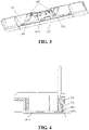
FIG. 4 is a schematic diagram showing that the far-field speech support realizes a lens function according to an embodiment of the present disclosure. -
FIG. 5 is a schematic structural diagram showing that the far-field speech support is fixed to a television body according to an embodiment of the present disclosure. - The above drawings have the following reference numerals: The drawings have the following symbols: 100, television; 101, television body; 102, front frame; 103, source cover plate; 200, far-field speech support; 201, base; 2011, transparent light guide plate; 202, far-field speech board installation portion; 2021, first through hole; 203, buckle structure; 2031, locking plate; 2032, limiting groove; 2033, first limiting portion; 2034, limiting plate; 2035, second limiting portion; 204, support portion; 205, infrared reflective portion; 2051, reflective surface; 206, first fixing portion; 207, second fixing portion; 208, third fixing portion; 2081, second through hole; 300, far-field speech board; 400, infrared receiving head assembly; 401, infrared receiving head mounting plate; and 402, infrared receiving head.
- The present disclosure provides a far-field speech support with a lens function and an electrical device. The far-field speech support provided by the present disclosure is suitable for electrical equipment with far-field speech functions, such as televisions and commercial monitors. The far-field speech support is made of a transparent polycarbonate material. After an infrared signal enters the transparent far-field speech support, the transparent far-field speech support acts as a lens to reflect the infrared signal to an infrared receiving head. In order to make purposes, technical solutions, and effects of the present invention clearer and more definite, the present invention will be further described in detail below with reference to accompanying drawings and embodiments. It should be understood that specific embodiments described herein are only used to explain the present invention, not used to limit the present invention.
- In embodiments and claims, terms "a/an" and "the", unless specifically defined herein otherwise, can generally refer to a single or plural form.
- Furthermore, if a description of the embodiments of the present disclosure comprises terms such as "first" and "second", the terms such as "first" and "second" are used merely for a purpose of description, but shall not be construed as indicating or implying relative importance or implicitly indicating the number of the indicated technical feature. Hence, a feature defined with "first", "second", or the like may explicitly or implicitly includes one or more of this feature. In addition, technical solutions of the embodiments may be combined with each other, as long as those skilled in the art can realize such combination. When a combination of the technical solutions is contradictory or cannot be realized, it should be considered that such combination of the technical solutions does not exist, and does not fall within the claimed scope of the present disclosure.
- Please refer to
FIG. 1 to FIG. 5 , the present disclosure describes an embodiment of applying a far-field speech support to a television. - As shown in
FIG. 1, FIG. 2 , andFIG. 3 , the far-field speech support with a lens function is applied to thetelevision 100. Thetelevision 100 includes atelevision body 101, a far-field speech board 300, an infraredreceiving head assembly 400, and the far-field speech stand 200. Specifically, the far-field speech support 200 is installed at a middle of a bottom of thetelevision body 101, like a "slender chin", so that a protruding part of the far-field speech support 200 is very narrow and has a very slight influence on appearance. - Specifically, please refer to
FIG. 1, FIG. 2 , andFIG. 4 , the far-field speech support 200 comprises abase 201, a far-field speechboard installation portion 202, a transparentlight guide plate 2011, abuckle structure 203, and an infraredreflective portion 205. The far-field speechboard installation portion 202 is vertically disposed on thebase 201. Thebuckle structure 203 is disposed on a side of the base 201 away from the far-field speechboard installation portion 202 and configured to install the infraredreceiving head assembly 400. The transparentlight guide plate 2011 is disposed on a bottom side of the far-field speechboard installation portion 202. The transparentlight guide plate 2011 is disposed at a middle of thebase 201. The infraredreflective portion 205 is disposed corresponding to the transparentlight guide plate 2011 and disposed below the infraredreceiving head assembly 400. The infraredreflective portion 205 is integrally formed with the transparentlight guide plate 2011. Areflective surface 2051 of the infrared reflective portion205 has an inclined angle α with a bottom surface of the transparentlight guide plate 2011. That is, the infraredreflective portion 205 is inclined in a direction away from the transparentlight guide plate 2011 to form a chamfer with a high-gloss surface, i.e. a reflective mirror surface. The far-field speech board 300 is adhered on the far-field speechboard installation portion 202 with a double-sided adhesive tape, such as a very high bond (VHB) tape, so that installation of the far-field speech board 300 is simpler. The infraredreceiving head assembly 400 comprises aninfrared receiving head 402 and an infrared receiving head mounting plate 401. The infrared receiving head mounting plate 401 is installed on the far-field speech support 200 and is connected to thebuckle structure 203. Theinfrared receiving head 402 is disposed on the infrared receiving head mounting plate 401. Theinfrared receiving head 402 is disposed directly above the infraredreflective portion 205. - The infrared
reflective portion 205 and the transparentlight guide plate 2011 are both made of a transparent polycarbonate material. The transparentlight guide plate 2011 and the infraredreflective portion 205 are transparent. After an infrared signal enters the transparentlight guide plate 2011, the infrared signal reaches the infraredreflective portion 205. When the infrared signal reaches thereflective surface 2051 of the infraredreflective portion 205, that is, when the infrared signal reaches the high-gloss surface of the chamfer of the infraredreflective portion 205, the infrared signal is reflected to theinfrared receiving head 402 by thereflective surface 2051, i.e., the high-gloss surface (the reflective mirror surface) of the chamfer, so that theinfrared receiving head 402 can receive a signal sent by a remote controller. That is, the transparentlight guide plate 2011 and the infraredreflective portion 205 of the far-field speech support 200 of the present disclosure function as lenses. This reduces the number of lenses and provides an installation space for the far-field speech board 300, thereby facilitating installation of the far-field speech board 300 and avoiding a conflict between the far-field speech board 300 and a lens. Compared with a current method for installing the far-field speech board 300, this method does not occupy space and is more aesthetically pleasing. - Please refer to
FIG. 1 , in an embodiment, the far-field speechboard installation portion 202 is provided with a plurality of first throughholes 2021. The first throughholes 2021 are configured as a plurality of microphone holes of the far-field speech board 300, which can transmit sound, thereby realizing a far-field speech function. Furthermore, when the far-field speech board 300 is installed in afront frame 102 in the prior art, a front of thefront frame 102 needs to be provided with a plurality of sound holes, which affects appearance. Compared with the prior art, a method for installing the far-field speech board 300 of the present disclosure is more aesthetically pleasing. - Please refer to
FIG. 2 , in an embodiment, thebuckle structure 203 comprises alocking plate 2031 and a limitingplate 2034. Specifically, thelocking plate 2031 and the limitingplate 2034 are oppositely disposed on thebase 201. Thelocking plate 2031 is provided with a limitinggroove 2032 and a first limitingportion 2033. The limitingplate 2034 is provided with a second limitingportion 2035. - Furthermore, the transparent
light guide plate 2011 is provided with asupport portion 204. Thesupport portion 204 is disposed between the lockingplate 2031 and the limiting plate2034. Thesupport portion 204 is integrally formed with the transparentlight guide plate 2011 and the infraredreflective portion 205. Thesupport portion 204 is also made of the transparent polycarbonate material, so that the infrared signal reflected by the infraredreflective portion 205 can be transmitted to the infraredreceiving head assembly 400 through the supportingportion 204. It should be noted that the far-field speech support 200 may be integrally injection-molded, and the far-field speech support 200 is made of the transparent polycarbonate material. When installing the infraredreceiving head assembly 400, the infrared receiving head mounting plate 401 is buckled on thelocking plate 2031 and the limitingplate 2034. The limitinggroove 2032 and the limitingplate 2034 limit the infrared receiving head mounting plate 401 to move in front, rear, left, and right directions, the first limitingportion 2033 and the second limitingportion 2035 limit the infrared receiving head mounting plate 401 to move in an up-down direction, and thesupport portion 204 supports the infrared receiving head mounting plate 401, so as to stably install the infrared receiving head mounting plate 401 on the far-field speech support 200. Please refer toFIG. 2 , in an embodiment, thesupport portion 204 is disposed perpendicular to the transparentlight guide plate 2011. When an external infrared signal is emitted toward the transparent light guide plate 2011 (please refer to a direction of an arrow inFIG. 3 ), the reflective mirror surface of the infraredreflective portion 205 reflects the infrared signal to theinfrared receiving head 402, so as to achieve a purpose of receiving a remote control signal. - Please refer to
FIG. 2 , in an embodiment, thebase 201 is provided with afirst fixing portion 206, and the far-field speechboard installation portion 202 is provided with asecond fixing portion 207. Thetelevision 100 further comprises afront frame 102. When the far-field speech support 200 needs to be installed, the far-field speech support 200 is inserted into thefront frame 102 of thetelevision 100, and is buckled to thefront frame 102 through thefirst fixing portion 206 and thesecond fixing portion 207. - Please refer to
FIG. 2 , in an embodiment, thebase 201 is provided with a plurality of third fixingportions 208, and each of thethird fixing portions 208 is provided with a second throughhole 2081. Thetelevision 100 further comprises asource cover plate 103. The second throughholes 2081 are screw holes. After the far-field speech support 200 is installed in thefront frame 102, the far-field speech support 200 is fixedly connected to thesource cover plate 103 of thetelevision 100 by screws through thethird fixing portions 208. - In the above, the present disclosure provides a far-field speech support with a lens function and an electrical device. The far-field speech support includes: a base, a far-field speech board installation portion disposed on the base and configured to install a far-field speech board, a buckle structure disposed on the base and configured to install an infrared receiving head assembly, and an infrared reflective portion disposed corresponding to the transparent light guide plate and disposed below the infrared receiving head assembly. The far-field speech support is integrally formed, and the far-field speech support is made of a transparent polycarbonate material. When an infrared signal enters the far-field speech support, it passes through the transparent light guide plate, and then is reflected to an infrared receiving head through the infrared reflective portion. Therefore, the far-field speech support acts as a lens, which reduces the number of lenses. Furthermore, the far-field speech support provides an installation space for the far-field speech board, which facilitates installation of the far-field speech board.
- It should be understood that application of the present disclosure is not limited to the above examples. Those skilled in the art may make improvements or changes based on the above description, and all such improvements or changes shall fall within the scope of the claims of the present disclosure.
Claims (18)
- A far-field speech support with a lens function, comprising:a base;a far-field speech board installation portion disposed on the base and configured to install a far-field speech board;a transparent light guide plate disposed on a bottom side of the far-field speech board installation portion;a buckle structure disposed on the base and configured to install an infrared receiving head assembly; andan infrared reflective portion disposed corresponding to the transparent light guide plate and disposed below the infrared receiving head assembly.
- The far-field speech support with the lens function as claimed in claim 1, characterized in that the infrared reflective portion is integrally formed with the transparent light guide plate.
- The far-field speech support with the lens function as claimed in claim 1, characterized in that a reflective surface of the infrared reflective portion has an inclined angle with a bottom surface of the transparent light guide plate.
- The far-field speech support with the lens function as claimed in claim 1, characterized in that the far-field speech board installation portion is provided with a plurality of first through holes.
- The far-field speech support with the lens function as claimed in claim 4, characterized in that the first through holes are configured as microphone holes for the far-field speech board.
- The far-field speech support with the lens function as claimed in claim 1, characterized in that the buckle structure is disposed on a side of the base away from the far-field speech board installation portion.
- The far-field speech support with the lens function as claimed in claim 1, characterized in that the buckle structure comprises a locking plate and a limiting plate, and the locking plate and the limiting plate are oppositely disposed on the base.
- The far-field speech support with the lens function as claimed in claim 7, characterized in that the locking plate is provided with a limiting groove and a first limiting portion, and the limiting plate is provided with a second limiting portion.
- The far-field speech support with the lens function as claimed in claim 7, characterized in that the transparent light guide plate is provided with a support portion, the support portion is disposed between the locking plate and the limiting plate, and the support portion is integrally formed with the transparent light guide plate and the infrared reflective portion.
- The far-field speech support with the lens function as claimed in claim 9, characterized in that the support portion is disposed perpendicular to the transparent light guide plate.
- The far-field speech support with the lens function as claimed in claim 9, characterized in that the transparent light guide plate, the infrared reflective portion, and the support portion are made of polycarbonate.
- The far-field speech support with the lens function as claimed in claim 1, characterized in that the transparent light guide plate is disposed at a middle of the base.
- The far-field speech support with the lens function as claimed in claim 1, characterized in that the base is provided with a first fixing portion, and the far-field speech board installation portion is provided with a second fixing portion.
- The far-field speech support with the lens function as claimed in claim 1, characterized in that the base is provided with a plurality of third fixing portions, and each of the third fixing portions is provided with a second through hole.
- An electrical device, comprising the far-field speech board, the infrared receiving head assembly, and the far-field speech support with the lens function as claimed in any one of claims 1 to 14, wherein the far-field speech board is disposed on the far-field speech board installation portion, and the infrared receiving head assembly is disposed on the far-field speech support and is connected to the buckle structure.
- The electrical device as claimed in claim 15, characterized in that the far-field speech board is adhered to a back surface of the far-field speech board installation portion.
- The electrical device as claimed in claim 15, characterized in that the infrared receiving head assembly comprises an infrared receiving head and an infrared receiving head mounting plate, the infrared receiving head mounting plate is disposed on the buckle structure, and the infrared receiving head is disposed on the infrared receiving head mounting plate.
- The electrical device as claimed in claim 17, characterized in that the infrared receiving head is disposed directly above the infrared reflective portion.
Applications Claiming Priority (2)
| Application Number | Priority Date | Filing Date | Title |
|---|---|---|---|
| CN201922490044.8U CN210839894U (en) | 2019-12-30 | 2019-12-30 | A far-field voice stand with lens function and electrical equipment |
| PCT/CN2020/111282 WO2021135298A1 (en) | 2019-12-30 | 2020-08-26 | Far-field sound support frame having lens function, and electrical apparatus |
Publications (3)
| Publication Number | Publication Date |
|---|---|
| EP4086896A1 true EP4086896A1 (en) | 2022-11-09 |
| EP4086896A4 EP4086896A4 (en) | 2024-01-03 |
| EP4086896B1 EP4086896B1 (en) | 2025-06-04 |
Family
ID=71265438
Family Applications (1)
| Application Number | Title | Priority Date | Filing Date |
|---|---|---|---|
| EP20909998.5A Active EP4086896B1 (en) | 2019-12-30 | 2020-08-26 | Far-field sound support frame having lens function, and electrical apparatus |
Country Status (4)
| Country | Link |
|---|---|
| US (1) | US11962830B2 (en) |
| EP (1) | EP4086896B1 (en) |
| CN (1) | CN210839894U (en) |
| WO (1) | WO2021135298A1 (en) |
Cited By (1)
| Publication number | Priority date | Publication date | Assignee | Title |
|---|---|---|---|---|
| EP4478345A1 (en) * | 2023-06-13 | 2024-12-18 | LG Electronics Inc. | Display device |
Families Citing this family (1)
| Publication number | Priority date | Publication date | Assignee | Title |
|---|---|---|---|---|
| CN210839894U (en) * | 2019-12-30 | 2020-06-23 | 深圳Tcl数字技术有限公司 | A far-field voice stand with lens function and electrical equipment |
Family Cites Families (25)
| Publication number | Priority date | Publication date | Assignee | Title |
|---|---|---|---|---|
| WO2005041614A2 (en) * | 2003-10-23 | 2005-05-06 | Westinghouse Digital Electronics, Llc | Acoustic frame for flat screen television |
| US20070103432A1 (en) * | 2005-11-04 | 2007-05-10 | Microsoft Corporation | Optical sub-frame for interactive display system |
| US8305428B2 (en) * | 2007-04-18 | 2012-11-06 | Inlife-Handnet Co., Ltd | Stereo video shooting and viewing device |
| CN102066832B (en) * | 2008-06-27 | 2013-05-01 | 夏普株式会社 | Backlight device, display device, and television receiver |
| US8736228B1 (en) * | 2010-12-20 | 2014-05-27 | Amazon Technologies, Inc. | Charging an electronic device including traversing at least a portion of a path with an apparatus |
| JP5771002B2 (en) * | 2010-12-22 | 2015-08-26 | 株式会社東芝 | Speech recognition apparatus, speech recognition method, and television receiver equipped with speech recognition apparatus |
| US20120207333A1 (en) * | 2011-02-15 | 2012-08-16 | Tzu-Chung Chang | Sound Box |
| US20160099596A1 (en) * | 2011-06-16 | 2016-04-07 | Tseng-Lu Chien | Quickly Charger has USB Charging-Ports for Time Related Device or Lighting Device |
| US9462340B1 (en) * | 2011-10-13 | 2016-10-04 | Trevor Mathurin | Voice/manual activated and integrated audio/video multi-media, multi-interface system |
| JP5831404B2 (en) * | 2012-08-30 | 2015-12-09 | ヤマハ株式会社 | Relay device and speaker device |
| JP5633544B2 (en) * | 2012-08-30 | 2014-12-03 | ヤマハ株式会社 | Electrical device, remote control signal determination program, and remote control signal processing method |
| KR101573490B1 (en) * | 2014-10-02 | 2015-12-11 | 레이트론(주) | Light Signal Transmitting and Receiving Apparatus using Light Guide |
| KR102025506B1 (en) * | 2016-05-24 | 2019-09-25 | 뱅 앤 올룹슨 에이/에스 | Modular TV Architecture |
| US10477291B2 (en) * | 2016-07-27 | 2019-11-12 | Bose Corporation | Audio device |
| CN106303711B (en) * | 2016-08-09 | 2019-12-03 | 深圳Tcl数字技术有限公司 | Interface display method and television system |
| KR101800201B1 (en) * | 2017-07-25 | 2017-11-23 | 주식회사 탑시스템 | Emote controller with speech recognition for adjusting updown and angle of television |
| US10381008B1 (en) * | 2017-11-18 | 2019-08-13 | Tp Lab, Inc. | Voice-based interactive network monitor |
| CN108004504B (en) * | 2018-01-02 | 2019-06-14 | 京东方科技集团股份有限公司 | a mask |
| CN208477913U (en) * | 2018-06-27 | 2019-02-05 | 百度在线网络技术(北京)有限公司 | Voice control box |
| CN113841467A (en) * | 2019-05-23 | 2021-12-24 | 3M创新有限公司 | Fastener for components in electronic devices |
| CN110493092B (en) * | 2019-08-28 | 2022-02-01 | 深圳市云之尚网络科技有限公司 | Universal remote control based on far-field voice and IOT (input/output) and household appliance remote control method |
| CN210839894U (en) * | 2019-12-30 | 2020-06-23 | 深圳Tcl数字技术有限公司 | A far-field voice stand with lens function and electrical equipment |
| CN112235666B (en) * | 2020-09-28 | 2026-01-02 | 北京小米移动软件有限公司 | Speaker components, display devices, audio output methods and apparatus |
| CN213691248U (en) * | 2020-10-22 | 2021-07-13 | 合肥维信诺科技有限公司 | Display panel and display device |
| EP4519722A1 (en) * | 2022-05-03 | 2025-03-12 | Corning Incorporated | Transparent articles with high shallow hardness and display devices with the same |
-
2019
- 2019-12-30 CN CN201922490044.8U patent/CN210839894U/en active Active
-
2020
- 2020-08-26 EP EP20909998.5A patent/EP4086896B1/en active Active
- 2020-08-26 WO PCT/CN2020/111282 patent/WO2021135298A1/en not_active Ceased
- 2020-08-26 US US17/757,933 patent/US11962830B2/en active Active
Cited By (2)
| Publication number | Priority date | Publication date | Assignee | Title |
|---|---|---|---|---|
| EP4478345A1 (en) * | 2023-06-13 | 2024-12-18 | LG Electronics Inc. | Display device |
| US12561040B2 (en) | 2023-06-13 | 2026-02-24 | Lg Electronics Inc. | Display device |
Also Published As
| Publication number | Publication date |
|---|---|
| EP4086896B1 (en) | 2025-06-04 |
| US20230042660A1 (en) | 2023-02-09 |
| CN210839894U (en) | 2020-06-23 |
| US11962830B2 (en) | 2024-04-16 |
| EP4086896A4 (en) | 2024-01-03 |
| WO2021135298A1 (en) | 2021-07-08 |
Similar Documents
| Publication | Publication Date | Title |
|---|---|---|
| CN209804245U (en) | Information terminal | |
| US11693488B2 (en) | Voice-controlled electronic device | |
| US11962830B2 (en) | Far-field speech support with lens function and electrical device | |
| US20040239619A1 (en) | Flat type image display device | |
| EP3145180A1 (en) | Display apparatus and apparatus for controlling the same | |
| EP4068062A1 (en) | Touch frame and touch screen comprising same | |
| EP2211541B1 (en) | Speaker mounting member for display apparatus | |
| WO2021083361A1 (en) | Display device | |
| WO2021036310A1 (en) | Display device | |
| CN216412127U (en) | Touch display module and display device | |
| US20120162135A1 (en) | Optical touch apparatus | |
| WO2025218317A1 (en) | Display device | |
| CN221326895U (en) | Display screen and electronic equipment | |
| CN112263123A (en) | Combined display mirror and mirror surface display equipment | |
| CN211296779U (en) | a camera | |
| CN209537002U (en) | Water purifier display module and water purifier | |
| CN109151655B (en) | Casing assembly and intelligent sound box | |
| CN111246141B (en) | Pickup box body of television | |
| CN213244182U (en) | Voice device and display device thereof | |
| US12284773B2 (en) | Strip-like screen display device | |
| CN209002156U (en) | A kind of installing mechanism for laser theatre projector remote speech microphone | |
| CN224096332U (en) | Display device | |
| CN111343399B (en) | Television with remote pickup function | |
| CN221079546U (en) | Display device | |
| CN105301821B (en) | Liquid crystal display device |
Legal Events
| Date | Code | Title | Description |
|---|---|---|---|
| STAA | Information on the status of an ep patent application or granted ep patent |
Free format text: STATUS: THE INTERNATIONAL PUBLICATION HAS BEEN MADE |
|
| PUAI | Public reference made under article 153(3) epc to a published international application that has entered the european phase |
Free format text: ORIGINAL CODE: 0009012 |
|
| STAA | Information on the status of an ep patent application or granted ep patent |
Free format text: STATUS: REQUEST FOR EXAMINATION WAS MADE |
|
| 17P | Request for examination filed |
Effective date: 20220330 |
|
| AK | Designated contracting states |
Kind code of ref document: A1 Designated state(s): AL AT BE BG CH CY CZ DE DK EE ES FI FR GB GR HR HU IE IS IT LI LT LU LV MC MK MT NL NO PL PT RO RS SE SI SK SM TR |
|
| DAV | Request for validation of the european patent (deleted) | ||
| DAX | Request for extension of the european patent (deleted) | ||
| A4 | Supplementary search report drawn up and despatched |
Effective date: 20231204 |
|
| RIC1 | Information provided on ipc code assigned before grant |
Ipc: G08C 23/04 20060101ALI20231128BHEP Ipc: G10L 15/22 20060101AFI20231128BHEP |
|
| REG | Reference to a national code |
Ref country code: DE Free format text: PREVIOUS MAIN CLASS: G10L0015220000 Ref country code: DE Ref legal event code: R079 Ref document number: 602020052473 Country of ref document: DE Free format text: PREVIOUS MAIN CLASS: G10L0015220000 Ipc: H04R0001020000 |
|
| GRAP | Despatch of communication of intention to grant a patent |
Free format text: ORIGINAL CODE: EPIDOSNIGR1 |
|
| STAA | Information on the status of an ep patent application or granted ep patent |
Free format text: STATUS: GRANT OF PATENT IS INTENDED |
|
| RIC1 | Information provided on ipc code assigned before grant |
Ipc: G08C 23/04 20060101ALI20241220BHEP Ipc: H04R 1/02 20060101AFI20241220BHEP |
|
| INTG | Intention to grant announced |
Effective date: 20250116 |
|
| P01 | Opt-out of the competence of the unified patent court (upc) registered |
Free format text: CASE NUMBER: APP_6802/2025 Effective date: 20250210 |
|
| GRAS | Grant fee paid |
Free format text: ORIGINAL CODE: EPIDOSNIGR3 |
|
| GRAA | (expected) grant |
Free format text: ORIGINAL CODE: 0009210 |
|
| STAA | Information on the status of an ep patent application or granted ep patent |
Free format text: STATUS: THE PATENT HAS BEEN GRANTED |
|
| AK | Designated contracting states |
Kind code of ref document: B1 Designated state(s): AL AT BE BG CH CY CZ DE DK EE ES FI FR GB GR HR HU IE IS IT LI LT LU LV MC MK MT NL NO PL PT RO RS SE SI SK SM TR |
|
| REG | Reference to a national code |
Ref country code: GB Ref legal event code: FG4D |
|
| REG | Reference to a national code |
Ref country code: CH Ref legal event code: EP |
|
| REG | Reference to a national code |
Ref country code: DE Ref legal event code: R096 Ref document number: 602020052473 Country of ref document: DE |
|
| REG | Reference to a national code |
Ref country code: IE Ref legal event code: FG4D |
|
| REG | Reference to a national code |
Ref country code: NL Ref legal event code: MP Effective date: 20250604 |
|
| PG25 | Lapsed in a contracting state [announced via postgrant information from national office to epo] |
Ref country code: FI Free format text: LAPSE BECAUSE OF FAILURE TO SUBMIT A TRANSLATION OF THE DESCRIPTION OR TO PAY THE FEE WITHIN THE PRESCRIBED TIME-LIMIT Effective date: 20250604 Ref country code: ES Free format text: LAPSE BECAUSE OF FAILURE TO SUBMIT A TRANSLATION OF THE DESCRIPTION OR TO PAY THE FEE WITHIN THE PRESCRIBED TIME-LIMIT Effective date: 20250604 |
|
| PGFP | Annual fee paid to national office [announced via postgrant information from national office to epo] |
Ref country code: DE Payment date: 20250820 Year of fee payment: 6 |
|
| REG | Reference to a national code |
Ref country code: LT Ref legal event code: MG9D |
|
| PG25 | Lapsed in a contracting state [announced via postgrant information from national office to epo] |
Ref country code: GR Free format text: LAPSE BECAUSE OF FAILURE TO SUBMIT A TRANSLATION OF THE DESCRIPTION OR TO PAY THE FEE WITHIN THE PRESCRIBED TIME-LIMIT Effective date: 20250905 Ref country code: NO Free format text: LAPSE BECAUSE OF FAILURE TO SUBMIT A TRANSLATION OF THE DESCRIPTION OR TO PAY THE FEE WITHIN THE PRESCRIBED TIME-LIMIT Effective date: 20250904 |
|
| PG25 | Lapsed in a contracting state [announced via postgrant information from national office to epo] |
Ref country code: PL Free format text: LAPSE BECAUSE OF FAILURE TO SUBMIT A TRANSLATION OF THE DESCRIPTION OR TO PAY THE FEE WITHIN THE PRESCRIBED TIME-LIMIT Effective date: 20250604 |
|
| PG25 | Lapsed in a contracting state [announced via postgrant information from national office to epo] |
Ref country code: BG Free format text: LAPSE BECAUSE OF FAILURE TO SUBMIT A TRANSLATION OF THE DESCRIPTION OR TO PAY THE FEE WITHIN THE PRESCRIBED TIME-LIMIT Effective date: 20250604 |
|
| PG25 | Lapsed in a contracting state [announced via postgrant information from national office to epo] |
Ref country code: HR Free format text: LAPSE BECAUSE OF FAILURE TO SUBMIT A TRANSLATION OF THE DESCRIPTION OR TO PAY THE FEE WITHIN THE PRESCRIBED TIME-LIMIT Effective date: 20250604 |
|
| PG25 | Lapsed in a contracting state [announced via postgrant information from national office to epo] |
Ref country code: RS Free format text: LAPSE BECAUSE OF FAILURE TO SUBMIT A TRANSLATION OF THE DESCRIPTION OR TO PAY THE FEE WITHIN THE PRESCRIBED TIME-LIMIT Effective date: 20250904 |
|
| PG25 | Lapsed in a contracting state [announced via postgrant information from national office to epo] |
Ref country code: LV Free format text: LAPSE BECAUSE OF FAILURE TO SUBMIT A TRANSLATION OF THE DESCRIPTION OR TO PAY THE FEE WITHIN THE PRESCRIBED TIME-LIMIT Effective date: 20250604 |
|
| PG25 | Lapsed in a contracting state [announced via postgrant information from national office to epo] |
Ref country code: NL Free format text: LAPSE BECAUSE OF FAILURE TO SUBMIT A TRANSLATION OF THE DESCRIPTION OR TO PAY THE FEE WITHIN THE PRESCRIBED TIME-LIMIT Effective date: 20250604 |
|
| PG25 | Lapsed in a contracting state [announced via postgrant information from national office to epo] |
Ref country code: PT Free format text: LAPSE BECAUSE OF FAILURE TO SUBMIT A TRANSLATION OF THE DESCRIPTION OR TO PAY THE FEE WITHIN THE PRESCRIBED TIME-LIMIT Effective date: 20251006 |
|
| REG | Reference to a national code |
Ref country code: AT Ref legal event code: MK05 Ref document number: 1801509 Country of ref document: AT Kind code of ref document: T Effective date: 20250604 |
|
| PG25 | Lapsed in a contracting state [announced via postgrant information from national office to epo] |
Ref country code: IS Free format text: LAPSE BECAUSE OF FAILURE TO SUBMIT A TRANSLATION OF THE DESCRIPTION OR TO PAY THE FEE WITHIN THE PRESCRIBED TIME-LIMIT Effective date: 20251004 |
|
| PG25 | Lapsed in a contracting state [announced via postgrant information from national office to epo] |
Ref country code: SM Free format text: LAPSE BECAUSE OF FAILURE TO SUBMIT A TRANSLATION OF THE DESCRIPTION OR TO PAY THE FEE WITHIN THE PRESCRIBED TIME-LIMIT Effective date: 20250604 Ref country code: AT Free format text: LAPSE BECAUSE OF FAILURE TO SUBMIT A TRANSLATION OF THE DESCRIPTION OR TO PAY THE FEE WITHIN THE PRESCRIBED TIME-LIMIT Effective date: 20250604 |
|
| PG25 | Lapsed in a contracting state [announced via postgrant information from national office to epo] |
Ref country code: CZ Free format text: LAPSE BECAUSE OF FAILURE TO SUBMIT A TRANSLATION OF THE DESCRIPTION OR TO PAY THE FEE WITHIN THE PRESCRIBED TIME-LIMIT Effective date: 20250604 |
|
| PG25 | Lapsed in a contracting state [announced via postgrant information from national office to epo] |
Ref country code: EE Free format text: LAPSE BECAUSE OF FAILURE TO SUBMIT A TRANSLATION OF THE DESCRIPTION OR TO PAY THE FEE WITHIN THE PRESCRIBED TIME-LIMIT Effective date: 20250604 |
|
| PG25 | Lapsed in a contracting state [announced via postgrant information from national office to epo] |
Ref country code: SK Free format text: LAPSE BECAUSE OF FAILURE TO SUBMIT A TRANSLATION OF THE DESCRIPTION OR TO PAY THE FEE WITHIN THE PRESCRIBED TIME-LIMIT Effective date: 20250604 |
|
| PG25 | Lapsed in a contracting state [announced via postgrant information from national office to epo] |
Ref country code: IT Free format text: LAPSE BECAUSE OF FAILURE TO SUBMIT A TRANSLATION OF THE DESCRIPTION OR TO PAY THE FEE WITHIN THE PRESCRIBED TIME-LIMIT Effective date: 20250604 |
|
| PG25 | Lapsed in a contracting state [announced via postgrant information from national office to epo] |
Ref country code: RO Free format text: LAPSE BECAUSE OF FAILURE TO SUBMIT A TRANSLATION OF THE DESCRIPTION OR TO PAY THE FEE WITHIN THE PRESCRIBED TIME-LIMIT Effective date: 20250604 |
|
| REG | Reference to a national code |
Ref country code: DE Ref legal event code: R097 Ref document number: 602020052473 Country of ref document: DE |
|
| REG | Reference to a national code |
Ref country code: CH Ref legal event code: H13 Free format text: ST27 STATUS EVENT CODE: U-0-0-H10-H13 (AS PROVIDED BY THE NATIONAL OFFICE) Effective date: 20260324 |
|
| PG25 | Lapsed in a contracting state [announced via postgrant information from national office to epo] |
Ref country code: MC Free format text: LAPSE BECAUSE OF FAILURE TO SUBMIT A TRANSLATION OF THE DESCRIPTION OR TO PAY THE FEE WITHIN THE PRESCRIBED TIME-LIMIT Effective date: 20250604 |
|
| PLBE | No opposition filed within time limit |
Free format text: ORIGINAL CODE: 0009261 |
|
| STAA | Information on the status of an ep patent application or granted ep patent |
Free format text: STATUS: NO OPPOSITION FILED WITHIN TIME LIMIT |
|
| PG25 | Lapsed in a contracting state [announced via postgrant information from national office to epo] |
Ref country code: DK Free format text: LAPSE BECAUSE OF FAILURE TO SUBMIT A TRANSLATION OF THE DESCRIPTION OR TO PAY THE FEE WITHIN THE PRESCRIBED TIME-LIMIT Effective date: 20250604 |
|
| PG25 | Lapsed in a contracting state [announced via postgrant information from national office to epo] |
Ref country code: LU Free format text: LAPSE BECAUSE OF NON-PAYMENT OF DUE FEES Effective date: 20250826 |
|
| REG | Reference to a national code |
Ref country code: CH Ref legal event code: L10 Free format text: ST27 STATUS EVENT CODE: U-0-0-L10-L00 (AS PROVIDED BY THE NATIONAL OFFICE) Effective date: 20260416 |
|
| PG25 | Lapsed in a contracting state [announced via postgrant information from national office to epo] |
Ref country code: CH Free format text: LAPSE BECAUSE OF NON-PAYMENT OF DUE FEES Effective date: 20250831 |
|
| REG | Reference to a national code |
Ref country code: BE Ref legal event code: MM Effective date: 20250831 |
|
| 26N | No opposition filed |
Effective date: 20260305 |
|
| GBPC | Gb: european patent ceased through non-payment of renewal fee |
Effective date: 20250904 |
|
| PG25 | Lapsed in a contracting state [announced via postgrant information from national office to epo] |
Ref country code: LT Free format text: LAPSE BECAUSE OF FAILURE TO SUBMIT A TRANSLATION OF THE DESCRIPTION OR TO PAY THE FEE WITHIN THE PRESCRIBED TIME-LIMIT Effective date: 20250604 |
|
| PG25 | Lapsed in a contracting state [announced via postgrant information from national office to epo] |
Ref country code: GB Free format text: LAPSE BECAUSE OF NON-PAYMENT OF DUE FEES Effective date: 20250904 |
|
| PG25 | Lapsed in a contracting state [announced via postgrant information from national office to epo] |
Ref country code: BE Free format text: LAPSE BECAUSE OF NON-PAYMENT OF DUE FEES Effective date: 20250831 Ref country code: IE Free format text: LAPSE BECAUSE OF NON-PAYMENT OF DUE FEES Effective date: 20250826 |
|
| PG25 | Lapsed in a contracting state [announced via postgrant information from national office to epo] |
Ref country code: FR Free format text: LAPSE BECAUSE OF NON-PAYMENT OF DUE FEES Effective date: 20250831 |
|
| PG25 | Lapsed in a contracting state [announced via postgrant information from national office to epo] |
Ref country code: SE Free format text: LAPSE BECAUSE OF FAILURE TO SUBMIT A TRANSLATION OF THE DESCRIPTION OR TO PAY THE FEE WITHIN THE PRESCRIBED TIME-LIMIT Effective date: 20250604 |