EP4086682A1 - Sliding tray for fiber optic panel assembly - Google Patents
Sliding tray for fiber optic panel assembly Download PDFInfo
- Publication number
- EP4086682A1 EP4086682A1 EP22173999.8A EP22173999A EP4086682A1 EP 4086682 A1 EP4086682 A1 EP 4086682A1 EP 22173999 A EP22173999 A EP 22173999A EP 4086682 A1 EP4086682 A1 EP 4086682A1
- Authority
- EP
- European Patent Office
- Prior art keywords
- fiber optic
- sliding tray
- panel assembly
- module
- modules
- Prior art date
- Legal status (The legal status is an assumption and is not a legal conclusion. Google has not performed a legal analysis and makes no representation as to the accuracy of the status listed.)
- Granted
Links
Images







Classifications
-
- G—PHYSICS
- G02—OPTICS
- G02B—OPTICAL ELEMENTS, SYSTEMS OR APPARATUS
- G02B6/00—Light guides; Structural details of arrangements comprising light guides and other optical elements, e.g. couplings
- G02B6/44—Mechanical structures for providing tensile strength and external protection for fibres, e.g. optical transmission cables
- G02B6/4439—Auxiliary devices
- G02B6/444—Systems or boxes with surplus lengths
- G02B6/4452—Distribution frames
- G02B6/44526—Panels or rackmounts covering a whole width of the frame or rack
-
- G—PHYSICS
- G02—OPTICS
- G02B—OPTICAL ELEMENTS, SYSTEMS OR APPARATUS
- G02B6/00—Light guides; Structural details of arrangements comprising light guides and other optical elements, e.g. couplings
- G02B6/44—Mechanical structures for providing tensile strength and external protection for fibres, e.g. optical transmission cables
- G02B6/4439—Auxiliary devices
- G02B6/444—Systems or boxes with surplus lengths
- G02B6/4441—Boxes
- G02B6/4446—Cable boxes, e.g. splicing boxes with two or more multi fibre cables
-
- G—PHYSICS
- G02—OPTICS
- G02B—OPTICAL ELEMENTS, SYSTEMS OR APPARATUS
- G02B6/00—Light guides; Structural details of arrangements comprising light guides and other optical elements, e.g. couplings
- G02B6/24—Coupling light guides
- G02B6/36—Mechanical coupling means
- G02B6/38—Mechanical coupling means having fibre to fibre mating means
- G02B6/3807—Dismountable connectors, i.e. comprising plugs
- G02B6/381—Dismountable connectors, i.e. comprising plugs of the ferrule type, e.g. fibre ends embedded in ferrules, connecting a pair of fibres
- G02B6/3825—Dismountable connectors, i.e. comprising plugs of the ferrule type, e.g. fibre ends embedded in ferrules, connecting a pair of fibres with an intermediate part, e.g. adapter, receptacle, linking two plugs
-
- G—PHYSICS
- G02—OPTICS
- G02B—OPTICAL ELEMENTS, SYSTEMS OR APPARATUS
- G02B6/00—Light guides; Structural details of arrangements comprising light guides and other optical elements, e.g. couplings
- G02B6/44—Mechanical structures for providing tensile strength and external protection for fibres, e.g. optical transmission cables
- G02B6/4439—Auxiliary devices
- G02B6/444—Systems or boxes with surplus lengths
- G02B6/4452—Distribution frames
-
- G—PHYSICS
- G02—OPTICS
- G02B—OPTICAL ELEMENTS, SYSTEMS OR APPARATUS
- G02B6/00—Light guides; Structural details of arrangements comprising light guides and other optical elements, e.g. couplings
- G02B6/44—Mechanical structures for providing tensile strength and external protection for fibres, e.g. optical transmission cables
- G02B6/4439—Auxiliary devices
- G02B6/444—Systems or boxes with surplus lengths
- G02B6/4453—Cassettes
-
- G—PHYSICS
- G02—OPTICS
- G02B—OPTICAL ELEMENTS, SYSTEMS OR APPARATUS
- G02B6/00—Light guides; Structural details of arrangements comprising light guides and other optical elements, e.g. couplings
- G02B6/44—Mechanical structures for providing tensile strength and external protection for fibres, e.g. optical transmission cables
- G02B6/4439—Auxiliary devices
- G02B6/4471—Terminating devices ; Cable clamps
-
- G—PHYSICS
- G02—OPTICS
- G02B—OPTICAL ELEMENTS, SYSTEMS OR APPARATUS
- G02B6/00—Light guides; Structural details of arrangements comprising light guides and other optical elements, e.g. couplings
- G02B6/24—Coupling light guides
- G02B6/36—Mechanical coupling means
- G02B6/38—Mechanical coupling means having fibre to fibre mating means
- G02B6/3807—Dismountable connectors, i.e. comprising plugs
- G02B6/3873—Connectors using guide surfaces for aligning ferrule ends, e.g. tubes, sleeves, V-grooves, rods, pins, balls
- G02B6/3874—Connectors using guide surfaces for aligning ferrule ends, e.g. tubes, sleeves, V-grooves, rods, pins, balls using tubes, sleeves to align ferrules
- G02B6/3878—Connectors using guide surfaces for aligning ferrule ends, e.g. tubes, sleeves, V-grooves, rods, pins, balls using tubes, sleeves to align ferrules comprising a plurality of ferrules, branching and break-out means
- G02B6/3879—Linking of individual connector plugs to an overconnector, e.g. using clamps, clips, common housings comprising several individual connector plugs
-
- G—PHYSICS
- G02—OPTICS
- G02B—OPTICAL ELEMENTS, SYSTEMS OR APPARATUS
- G02B6/00—Light guides; Structural details of arrangements comprising light guides and other optical elements, e.g. couplings
- G02B6/44—Mechanical structures for providing tensile strength and external protection for fibres, e.g. optical transmission cables
- G02B6/4439—Auxiliary devices
- G02B6/444—Systems or boxes with surplus lengths
- G02B6/44528—Patch-cords; Connector arrangements in the system or in the box
-
- G—PHYSICS
- G02—OPTICS
- G02B—OPTICAL ELEMENTS, SYSTEMS OR APPARATUS
- G02B6/00—Light guides; Structural details of arrangements comprising light guides and other optical elements, e.g. couplings
- G02B6/44—Mechanical structures for providing tensile strength and external protection for fibres, e.g. optical transmission cables
- G02B6/4439—Auxiliary devices
- G02B6/444—Systems or boxes with surplus lengths
- G02B6/4453—Cassettes
- G02B6/4455—Cassettes characterised by the way of extraction or insertion of the cassette in the distribution frame, e.g. pivoting, sliding, rotating or gliding
Definitions
- Fiber optic hardware is increasingly being used for a variety of applications, such as data transmission, video, broadband voice and the like.
- the fiber optic cable, connectors or electrical cables are connected to a fiber optic module mounted in a panel assembly disposed in a cable management rack located in a data distribution center or a server room.
- the fiber optic module provides cable-to-cable fiber optic connections and manages the polarity of fiber optic cable connections.
- the fiber optic module is mounted to a tray that may be further mounted to the panel assembly. The tray may be extended from the panel assembly like a drawer to allow technicians or operators to access to the fiber optic components, connectors, or fiber optic cables connected to the fiber optic module without, removing the fiber optic module from the panel assembly.
- a sliding tray that can slide multiple fiber optic modules simultaneously is provided.
- the sliding tray may be mounted in a fiber optic panel assembly.
- the fiber optic panel assembly includes a ceiling, a bottom cover, and two opposing sides defining an interior opening therein, a mounting bracket disposed on the bottom cover in the interior opening, the mounting bracket comprising a plurality of protruding posts extending outward from a supporting structure of the mounting bracket, and a sliding tray having a plurality of protruding structures, each protruding structure having a tip end configured to engage with an inner surface of the supporting structure.
- the mounting bracket includes a plurality of apertures defined between the plurality of protruding posts, wherein the apertures are configured to receive the protruding structures of the sliding tray therein.
- Each of the plurality of protruding structures of the sliding tray is configured to engage with a fiber optic module.
- Each of the plurality of protruding structures of the sliding tray comprises a mounting feature configured to secure the fiber optic module engaged therewith.
- the sliding tray further includes a plurality of apertures defined between the plurality of protruding structures, wherein the apertures are configured to receive the protruding posts of the mounting bracket.
- Each of the protruding structures of the sliding tray is configured to abut against and interleaved with the respective protruding post from the mounting bracket.
- the sliding tray further includes a guiding rail formed at edges of the sliding tray.
- the mounting bracket further includes a tray channel formed in the protruding post configured to engage with the guiding rail from the sliding tray.
- the sliding tray further includes a pull tab formed on a side of the sliding tray.
- the tray channel formed in the protruding post further includes a stop member disposed in the tray channel.
- Each of the plurality of protruding posts of the mounting bracket is configured to engage with a fiber optic module.
- the ceiling further includes a front top cover and a rear top cover defining the ceiling.
- a plurality of fiber optic modules is configured to engage with the protruding posts and the protruding structures.
- the fiber optic modules is vertically disposed in the interior opening in an array configuration.
- Each of the fiber optic module is configured to have adaptors vertically stacked therein.
- the adaptors are dual polarity adaptors.
- a fiber optic panel assembly having a ceiling, a bottom cover, and two opposing sides defining an interior opening therein, and a sliding tray disposed in the interior opening, the slidable tray configured to have a plurality of fiber optic modules vertically disposed in the sliding tray, wherein the sliding tray is configured to pull out selected fiber optic modules while maintaining non-selected fiber optic modules unmoved, wherein every other fiber optic module is staggered with respect to an adjacent fiber optic module disposed in the interior opening.
- a pull tab is attached to a side of the sliding tray.
- the selected fiber optic modules is engaged with the sliding tray and the non-selected fiber optic modules is engaged with a mounting bracket disposed in the interior opening.
- the fiber optic panel assembly further includes a sliding tray disposed in an interior opening of the fiber optic panel assembly, the slidable tray configured to have a plurality of fiber optic modules vertically disposed in the sliding tray, wherein the sliding tray is configured to pull out selected fiber optic modules while maintaining non-selected fiber optic modules unmoved, wherein every other fiber optic module is staggered with respect to an adjacent fiber optic module disposed in the interior opening.
- the fiber optic panel assembly is mounted on a rack in the cable management system.
- the fiber optic panel assembly provides a sliding tray that can slide selected fiber optic modules outward from other non-selected fiber optic modules disposed in the fiber optic panel assembly.
- Each fiber optic module is disposed vertically side by side in a multiple array configuration in the fiber optic panel assembly.
- every other fiber optic module such as a first set of fiber optic modules, is staggered in a longitudinal direction from a front end to a rear end of the fiber optic module, with respect to an adjacent fiber optic module, such as a second set of fiber optic module.
- the first set of fiber optic module is disposed rearwardly at a depth from the second set of the fiber optic module.
- the sliding tray may selectively pull out the first set or the second set of the fiber optic module outwardly relative to the other set so as to allow the technicians or operators to access to the fiber optic connectors in the fiber optic module with ease and reduced interference from the adjacent connectors. Furthermore, the sliding tray is also configured to pull out multiple selected fiber optic module simultaneously at one time so that a technician or an operator may visually identify and locate a target connector or cable in the fiber optic panel assembly efficiently and quickly with minimum search time. As the fiber optic modules are vertically disposed side by side in a closely packed arrangement, good utilization of the space defined in the fiber optic panel assembly may be obtained. Thus, the fiber optic module assembly disclosed herein provides a high density, ease and quick of access, and a small footprint for the desired cable and connector management and organization.
- Figures 1A-1C depict an example of a fiber optic connector 100 that provides dual polarity configurations.
- Figure 1A depicts a top view of the fiber optic connector 100.
- the fiber optic connector 100 comprises a body 102 that has two connector assemblies 110 (shown as 110a, 110b) connected thereto.
- Figure 1B depicts a front view of the fiber optic connector 100 illustrating the two connector assemblies 110 (shown as 110a, 110b) formed at a front section 103 of the fiber optic connector 100.
- Connector polarity indicia 104 is formed in the body 102 that indicates the polarity of the connector 100.
- the body 102 encases two optic fibers connecting to the two connector assemblies 110a, 110b respectively.
- the two optic fibers enclosed in the body 102 are connected to a cable 122 connected to the body 102.
- Figure 1C depicts a side view of the fiber optic connector 100.
- a latch 106 has a first end 120 connected to the connector assemblies 110a, 110b through a spring latch arm 130 and a second end 124 connected to the body 102.
- the latch 106 is used to secure the fiber optic connector 100 to an adaptor.
- the spring latch arm 130 releasably engages the latch 106.
- the spring latch arm 130 may be pressed to disengage from the latch 106.
- the connector assemblies 110a, 110b may be inserted into an adapter in a predetermined insertion direction.
- the adaptor may be disposed in a fiber optic module (not shown) mounted in a fiber management system.
- the latch 106 abuts against the spring latch arm 130 connected to the connector assemblies 110a, 110b for manually pressing the latter to move downwardly to allow disengagement between the connector assemblies 110a, 110b and the adapter and removal of the connector assemblies 110a, 110b out of the port.
- the spring latch arm 130 may be pressed to discharge the connector assemblies 110a, 110b from the body 102.
- the connector assemblies 110a, 110b may then be flipped and rotated for 180 degrees for polarity reversal and the latch 106 will then be re-attached to the opposite site of the body 102. Details of the adaptor that may be utilized to mate with the fiber optic connector 100 with dual polarity is illustrated below in detail with references to Figures 2A-2B .
- FIGs 2A-2B depict a perspective view and a front view, respectively, of an adaptor module 200 that may be mounted in a fiber optic panel assembly 700, which will be described later below with reference to Figure 7 .
- the adaptor module 200 includes a plurality of adaptors 250.
- the adaptor 250 is a dual polarity adaptor that may accommodate different orientations and geometrical configurations of the fiber optic connector 100 with different polarity configurations.
- the adaptor module 200 includes four adaptors 250 connected together, such as in a line or stack, so as to save space and maximize the usage of the space among the adaptors 250.
- the adaptor module 200 may have any numbers of the adaptors 250, such as at least one, at least two, at least three, at least four, at least five, at least six, or other numbers, as needed for different configurations of the patch panel on where the adaptor module 200 is configured to be mounted. It is noted that the density of fiber interconnection may be maximized by utilizing multiple adaptor modules 200 to be disposed side-by-side with multiple arrays. In this manner, the adaptor modules 200 are abutting one another in adjacent rows and adjacent columns, thus eliminating wasted space from between adjacent rows and adjacent columns, and providing a maximum density of connection adaptors 250 for the available opening space in the patch panel. In one example, the adaptor module 200 may be configured with any angular configuration to provide any connection orientation angle with respect to the patch panel.
- the adaptor 250 is configured to mate with a fiber optic connector, such as the fiber optic connector 100 depicted in Figures 1A-1C with different polarity configurations. It is noted that the adapter 250 may be mated with other types of the fiber optic connector as needed when the geometric configurations of the fiber optic connector can fit in the slot and/or ports defined in the adaptor 250.
- the adaptor module 200 includes a housing 202 having a top wall 204, a bottom wall 210, a first sidewall 212a, and a second sidewall 212b connecting the top wall 204 and the bottom wall 210.
- the top wall 204, the bottom wall 210, the first and second sidewall 212a, 212b define an interior region 206, such as a passage.
- the interior region 206 of the housing 202 is divided by a plurality of partition walls 225, defining multiple adaptors 250 with multiple connector connection ports 248 therein.
- the partition wall 225 is connected from the top wall 204 to the bottom wall 210.
- Each connector connection port 248 is configured to receive a fiber optic connector, such as the fiber optic connector 100 depicted in Figure 1A-1C .
- Each adaptor 250 defined in the adaptor module 200 may be symmetrically identical, and the first and second sidewalls 212a, 212b may also be symmetrically identical, such that upon rotation of the adaptor module 200 along with its longitudinal axis, the tops and bottoms are interchangeable.
- the adaptor 250 may serve as a termination point between an incoming fiber optic cable connected through a rear section 214 of the adaptor module 200 and an outgoing fiber optic cable, such as the cable 122, connected through the fiber optic connector 100.
- the example depicted herein has four adaptors defined in an adaptor module, it is noted that the numbers of the adaptors formed, configured in, or connected to form an adaptor module may be in any numbers as needed.
- the top wall 204, the bottom wall 210, the first and second sidewalls 212a, 202b of the housing 202 as well as the partition walls 225 may be integrally formed as an integral body from a polymeric material, such as molded plastic.
- Figure 2B depicts a front top view the adaptor module 200 that includes four adaptors 250.
- the partition wall 225 positioned in the interior region 206 defines the connector connection ports 248 in the adaptor 250.
- Each partition wall 225 has three portions, a first portion 242 and a second portion 238 with a center portion 236 sandwiched therebetween.
- the first portion 242 formed in each partition wall 225 horizontally defines a first slot 302 and the second portion 238 formed in each partition wall 225 horizontally defines a second slot 304 while the center portion 236 horizontally defines a center slot 306, as shown in the dotted lines, in the connector connection ports 248.
- the center slot 306 is configured to receive the connector assemblies 110 from the fiber optic connector 100 while the first slot 302 and the second slot 304 are configured to receive the latch 106 from the fiber optic connector 100.
- the latch 106 may be engaged with the first slot 302.
- the position of the latch 106 may be rotated for 180 degrees relative to the position of the latch 106 in a standard or straight polarity configuration.
- the latch 106 may be then engaged with the second slot 304 instead in light of the rotation of the fiber optic connector 100.
- a marking section 310 may be formed either at an upper end of the partition wall 225, such as in the first portion 242, or at a lower end of the partition wall 225, such as in the second portion 238, or other suitable places to provide a bold visual indication to the technician of the polarity configurations.
- the marking section 310 indicates standard polarity of the fiber optic connector 100 when the latch 106 is engaged with the first slot 302. It is noted that the marking section 310 may be formed at different locations of the adapter 250 as needed to facilitate indication of polarity configurations for the technician and operator.
- the fiber optic connector 100 with different polarity configurations may be easily installed and inserted into the adaptor 250 without additional direction changes, orientation alternation, or rotation flip either to the fiber optic connector or to the adaptor.
- the two additional slots, such as the first and the second slots 302, 304, formed laterally to the center slot 306, may accommodate different orientations and geometrical configurations of the fiber optic connector 100. Accordingly, the labor and cost for fiber optic management is reduced and the footprint required to place adaptors with different polarity configurations may be reduced.
- Figure 3A depicts an example of the adaptor modules 200 positioned in a fiber optic module 350.
- the fiber optic module 350 is configured to receive multiple adaptor modules 200, shown as 200a, 200b, 200c, aligned in a linear configuration.
- the fiber optic module 350 may be mounted inside the fiber optic panel assembly 700 (as shown in Figure 7 ) in a vertical configuration.
- the fiber optic module 350 may be disposed in a tray 900 (as shown in Figure 9 ) that may be extendable and slidable from the fiber optic panel assembly 700 like a drawer to allow technicians access to the adaptor 250 provided by the adaptor module 200 and any fiber optic cables or connectors connected to the adaptors 250 without removing the adaptor module 200 from the fiber optic panel assembly 700.
- three adaptor modules 200a, 200b, 200c are mounted in the fiber optic module 350, thus in total providing twelves adaptor ports 248 in one fiber optic module 350. It should be understood that in other examples the number of adapters and/or adaptor ports may be varied. It is noted that multiple fiber optic modules 350 may be connected side by side, end to end, in multiple arrays or columns, or any suitable configurations as needed.
- Figure 3B depicts an example of the two fiber optic connectors 100a, 100b with different polarity configurations connected to the adaptor modules 200a mounted in the fiber optic module 350.
- the two fiber optic connectors 100 with different polarity such as the first fiber optic connector 100a with the latch 106 positioned upward from the housing and the second fiber optic connector 100b with the latch 106 positioned downward from the housing (not shown in Figure 4B), may be both engaged in the adaptor module 200 through the first slot 302 and the second slot 304 formed in the adaptor 250.
- Figure 4 depicts a plurality of the fiber optic module 350 (shown as 350a, 350b) disposed side by side in an array and vertical configuration.
- the plurality of the fiber optic module 350 may be further placed and mounted into the fiber optic panel assembly 700 as shown in Figures 7 and 8 .
- each fiber optic module 350 may include three adaptor modules 200a, 200b 200c mounted therein.
- the partition walls 225 define four connector connection ports 248 in each adaptor modules 200a, 200b 200c.
- the first, center and second slots defined in the connector connection ports 248 is not shown and is eliminated in this example for ease of description.
- the marking section 310 is formed on one side of the partition wall 225 to provide a visual indication of the polarity configurations.
- the fiber optic module 350 has a front end 402, a back end 404 and two flat opposing sides 410, 412.
- a top edge 406 and a bottom edge 408 are connected among the front end 402, the back end 404 and the opposing sides 410, 412.
- Catches 414, 416 are formed on the top edge 406 and the bottom edge 408 respectively for securing the fiber optic module 350 to a mounting feature (such as the mounting feature 790 depicted in Figure 10B ) from the fiber optic panel assembly 700.
- the catches 414, 416 are a protrusion having a round shape and have a corresponding shaped portion located in the mounting feature from the fiber optic panel assembly 700 to enable engagement therewith.
- the fiber optic module 350 is slid within the fiber optic panel assembly 700 upon installation until the catch 414, 416 aligns with and is seated within a corresponding portion of the mounting feature from the fiber optic panel assembly 700, thus inhibiting inadvertent removal of the fiber optic module 350 from the fiber optic panel assembly 700.
- the catches 414, 416 are vertically aligned across the body of the fiber optic module 350.
- a pair of finger hooks 455 is provided and disposed on the back end 404 of the fiber optic module 350 so as to allow easy grabbing of the respective fiber optic module 350 from the arrays.
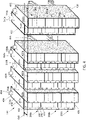
- every other fiber optic module 350 is staggered in a front end to a back end direction, such as a horizonal direction, with respect to an adjacent fiber optic module 350.
- the staggering of the fiber optic module 350 alternates across the arrays formed among the fiber optic module 350.
- a vertical surface of a first front end 402 of a first set of the fiber optic module 350, such as the first front end 402a of the fiber optic module 350a in odd numbers including a first, third and fifth fiber optic module and so on, are aligned.
- a second vertical surface of the second front end 402 of a second set of the fiber optic module 350 such as the second front end 402b of the fiber optic module 350b in even numbers including a second, fourth and sixth fiber optic module and so on, are aligned.
- the numbering of the fiber optic module 350 is started from a leftmost fiber optic module 350 disposed in the array, when viewing the array from the front end 402 of the fiber optic modules 350. Accordingly, the leftmost fiber optic module 350 is considered as the first fiber optic module, such as a first odd number fiber optic module.
- the fiber optic module abuts the leftmost fiber optic module 350 is considered as the second fiber optic module, such as a first even number fiber optic.
- the array may include 12 fiber optic modules, with a first fiber optic module disposed as the leftmost fiber optic module in the array and a twelfth fiber optic module disposed as the rightmost fiber optic module in the array.
- the first set of the fiber optic module 350a includes odd number fiber optic modules in the array while the second set of the fiber optic module 350b includes even number fiber optic modules.
- the first front end 402a of the first set of fiber optic module 350a and the second end 402b of the second set of the fiber optic module 350b are configured to be staggered in a front end to rear end direction at a depth 430.
- the second set of the fiber optic module 350b extends outwardly from the first set of fiber optic module 305b at the predetermined depth 430 so as to provide ample room to expose the connectors disposed in the fiber optic module 350 with relatively easy access for the technician to remove or install connectors as needed.
- the protrusion of the set of the fiber optic module may be in different arrangements, such as the first set of fiber optic module 350a extends outward from the second set of the fiber optic module 350b instead.
- the depth 350 may be between about 1 mm and about 500 mm.
- the array of the first and the second set of fiber optic module 350a, 350b may be arranged in a predetermined staggering manner.
- the first set of fiber optic module 350a may extend outward from the second set of fiber optic module 350b, or vise versa, when positioned into the fiber optic panel assembly 700.
- the rail channel and the sliding tray disposed in the fiber optic panel assembly 700 is configured to slide out a predetermined set of fiber optic module 350 with multiple fiber optic modules 350, such as the first set of fiber optic modules 350a with all odd number fiber optic module or the second set of fiber optic module 350b with all even number fiber optic module.
- the staggering configuration between the first and the second set of the fiber optic module 350a, 350b also allows the technician and/or the operator to easily install the connectors and/or cables in the fiber optic module with ample room, thus reducing unwanted removal of an adjacent connector.
- installation efficiency is enhanced and operating cost is reduced.
- Figure 5 depicts a side view of the fiber optic module 350 of Figure 4 .
- a plurality of cables 502 each connects to a respective fiber optic connector through the adaptors in each adaptor modules 200a, 200b, 200c. It is noted that a portion 504 of the side 410 utilized to enclose the adaptor modules 200a, 200b, 200c and the cables 502 is cut off in Figure 5 to show how the cables 502 are positioned in the interior opening defined in the fiber optic module 350 under the side 410.
- the plurality of cables 502 may be collected in an optic fiber ribbon 506 through an adaptor 506 or a connector for further connection.
- the catches 414, 416 are disposed on the top edge 406 and the bottom edge 408 respectively.
- the pair of the finger hooks 455 is provided and disposed on the back end 404 of the fiber optic module 350 to grab and pull the fiber optic module 350 for installation or uninstallation to and from the fiber optic panel assembly 700.
- Figure 6 depicts a side view of another example of a fiber optic module 600.
- more than three adaptor modules 200a, 200b, 200c may be disposed in the fiber optic module 600.
- nine adaptor modules 200a, 200b, 200c, 602a, 602b, 602c, 602d, 602e, 602f, in total are disposed in the fiber optic module 600.
- the closely packed adaptor modules 200a, 200b, 200c, 602a, 602b, 602c, 602d, 602e, 602f can provide connector connection with high density.
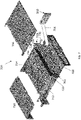
- Figure 7 depicts a top exploded view of an example of a fiber optic panel assembly 700.
- the fiber optic panel assembly 700 may accommodate the fiber optic module 350 of Figure 4 and 5 to be disposed in an interior opening 702, as shown by the arrow 704, defined in the fiber optic panel assembly 700. It is noted that when the high density fiber optic module 600 of Figure 6 is configured to be installed in the fiber optic panel assembly 700, the dimension of the fiber optic panel assembly 700 may be proportionally increased to accommodate the high density fiber optic module 600 of Figure 6 with the larger dimension.
- the fiber optic module 350 is disposed vertically in the interior opening 702 relative to a horizonal plane defined by a top front cover 706 or a bottom cover 708 of the fiber optic panel assembly 700.
- the top front cover 706 and a top rear cover 710 in combination define a top ceiling of the fiber optic panel assembly 700.
- Two opposing side panels 712, 714 are disposed in parallel connected between the top front cover 706, the top rear cover 710 and the bottom cover 708, defining the interior opening 702 therein.
- a mounting structure 720 may be disposed on the side panels 712, 714 that can assist mounting the fiber optic panel assembly 700 to a cable management system , such as a cable rack located in a server room or a data center.
- a sliding (or extendable) tray 725 may be mounted in the interior opening 702 of the fiber optic panel assembly 700.
- the sliding tray 725 may carry a plurality of fiber optic module 350 so as to slide or pull a predetermined set of the fiber optic module 350 outwardly relative to the fiber optic panel assembly 700.
- the sliding tray 725 has a front housing 734 configured to slide in and engage with a rail channel 730 defined in the side panels 712, 714 of the fiber optic panel assembly 700.
- a pull tab 732 is formed on sidewalls 738 of the front housing 734 to provide a gripping structure to allow the sliding tray 725 to easily be pulled out from and pushed into the fiber optic panel assembly 700.
- a mounting bracket 736 is disposed on the bottom cover 708 having a rear housing 735 in the fiber optic panel assembly 700.
- the mounting bracket 736 has a plurality of protruding posts 738 and a plurality of apertures 740 therebetween.
- the plurality of the protruding posts 738 extends from an inner surface 752 of a supporting structure 748.
- the plurality of apertures 740 is defined against and above the inner surface 752 of the supporting structure 748.
- a space defined in the rear housing 735 under each of the protruding posts 738 of the mounting bracket 736 is configured to encase one fiber optic module 350 therein.
- the plurality of apertures 740 of the mounting bracket 736 may receive a plurality of protruding structures 742 of the sliding tray 725, allowing the sliding tray 725 to engage with the mounting bracket 736 when the sliding tray 725 is retracted in a non-extended position.
- the plurality of protruding posts 738 may include tray channels 780 (also shown in Figure 9B ) configured to receive the plurality of protruding structures 742 of the sliding tray 725 slid therein. A tip end 752 of the protruding structures 742 of the sliding tray 725 abuts the inner surface 752 of the mounting bracket 736.
- each of the protruding structures 742 of the sliding tray 725 When retracted in the non-extended position, each of the protruding structures 742 of the sliding tray 725 abuts against and is interleaved with the respective protruding post 738 from the mounting bracket 736 with the tip end 752 mating with the inner surface 752.
- a space in the front housing 734 defined under each of the protruding structures 742 of the sliding tray 725 is configured to encase one fiber optic module 350 vertically disposed therein.
- the plurality of the protruding posts 738 of the mounting bracket 736 encases a first set of fiber optic module 350, such as a first, third, fifth fiber optic modules 350 (the odd number fiber optic modules 350a as shown in Figure 4 ) and so on while the plurality of protruding structures 742 of the sliding tray 725 encases a second set of fiber optic module 350, such as a second, fourth, sixth fiber optic modules 350 (the even number fiber optic modules 350b as shown in Figure 4 ) and so on.
- a first set of fiber optic module 350 such as a first, third, fifth fiber optic modules 350 (the odd number fiber optic modules 350a as shown in Figure 4 ) and so on
- the plurality of protruding structures 742 of the sliding tray 725 encases a second set of fiber optic module 350, such as a second, fourth, sixth fiber optic modules 350 (the even number fiber optic modules 350b as shown in Figure 4 ) and so on.
- the first set of fiber optic module 350a encased under the protruding posts 738 of the mounting bracket 736 and the second set of fiber optic module 350b encased under the protruding structures 742 of the sliding tray 725 are disposed against each other, but connected to different elements, such as the mounting bracket 736 and the sliding tray 725 respectively.
- the sliding tray 725 is slid and pulled outwardly to an extended position, only the second set of the fiber optic module 350b connected to the sliding tray 725 is pulled out, leaving the first set of the fiber optic module 350 remained at the non-extended position.
- the mounting bracket 736 may be fixedly mounted in the fiber optic panel assembly 700 by fastening features, such as bolts and nuts, screw fasteners and the like.
- Figure 8 depicts a top front end view of the fiber optic panel assembly 700 of Figure 7 with multiple arrays of fiber optic modules 350a, 350b mounted therein in a non-extended position.
- the first set of the fiber optic modules 350a and the second set of the fiber optic modules 350b are disposed in a staggering manner that the first and the second set of the fiber optic modules 350a, 350b are staggered at a depth relative to each other.
- the first set of the fiber optic modules 350a is extended and protruded outward and forward from the second set of the fiber optic modules 350a at the predetermined depth.
- the first set of the fiber optic modules 350a is engaged under the plurality of protruding posts 738 of the mounting bracket 736 respectively while the second set of the fiber optic modules 350b is engaged under the plurality of protruding structures 742 of the sliding tray 725 respectively.
- the pull tab 732 is pulled by a technician or an operator, the second set of the fiber optic modules 350b engaged under the plurality of protruding structures 742 of the sliding tray 725 are being pulled out, extending the sliding tray 725 outward to an extended position while the first set of the fiber optic modules 350a remains unmoved in the un-extended position.
- Figure 9A and 9B depicts top views of the fiber optic panel assembly 700 with the sliding tray 725 in an un-extended position and in an extended position respectively.
- the tip end 752 of the protruding structures 742 abuts and engages with the inner surface 754 of the mounting bracket 736, which is also shown in Figure 8 .
- the first front end 402a of the first set of the fiber optic modules 350a is extended outward from the second front end 402b of the second set of the fiber optic modules 350b.
- the second set of the fiber optic modules 350b becomes extended outwardly from the first set of the fiber optic modules 350a with the predetermined depth 430.
- the tip end 752 of the protruding structures 742 is pulled out into a position away from the inner surface 754 of the mounting bracket 736.
- a stopping member 782 may be disposed in the tray channel 780 in the mounting bracket 736 or to edge of the protruding structures 742 of the sliding tray 725 to prevent the sliding tray 725 from extending over the stopping member 782 and outside of tray channel 780 defined in the mounting bracket 736.
- the sliding tray 725 carries the second set of the fiber optic modules 350b, allowing the multiple connectors disposed in the second set of the fiber optic modules 350b to be pulled out simultaneously at one time, thus avoiding search time for a particular connector connected at a particular fiber optic module in the fiber optic panel assembly 700.
- the staggering configuration defined between the first and the second set of the fiber optic modules 350a, 350b may also provides an open space, defined by the depth 430, to allow an easy access for the technician and operator to connect or remove the connectors thereof.
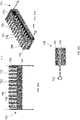
- Figure 10A-10C depicts a top view, a perspective front view and a side view of the sliding tray 725 that may be mounted in the fiber optic panel assembly 700.
- the sliding tray 725 includes the plurality of protruding structures 742 extending outwardly from the housing 734. A plurality of apertures 798 are defined between the protruding structures 742.
- the pull tab 732 is attached to a side of the housing 734.
- a guiding rail 792 is formed on the edges of the housing 734 configured to engage with the tray channel 780 in the mounting bracket 736, when the sliding tray 725 is mounted in the fiber optic panel assembly 700.
- a mounting feature 790 is formed on the protruding structures 742 that allows the catch 414, 416, as shown in Figure 4 , from the fiber optic module 350 to engage with the mounting feature 790 so as to secure the fiber optic module 350 in the sliding tray 725.
- the apertures 798 defined between the protruding structures 742 are configured to receive another set of the fiber optic module 350 that are not actuatable or slidable by the sliding tray 725.
- the sliding tray 725 is configured to selectively pull out a predetermined set of the fiber optic module 350 while another set of the fiber optic module 350 not mounted in the sliding tray 725 remained intact without movement.
- the protruding structures 742 may have a width similar to, or slightly larger than, the width of the fiber optic module 350 so as to receive the fiber optic module 350 under the protruding structures 742 in the sliding tray 725.
- the housing 734 and the protruding structures 742 of the sliding tray 725 may be formed as a unitary body that allows the pull tab 732 to be removably attached to the side of the sliding tray 725.
- Figure 11 depict an example fiber optic cable management system 1100 that my have the fiber optic panel assembly 700 of Figure 7 mounted on a rack 1102.
- the fiber optic panel assembly 700 may then be mounted on the rack 1102 by a fastening features, such as bolts, nuts or fastening screws.
- the rack 1102 may allow multiple fiber optic panel assembly 700 mounted thereon in the fiber optic cable management system.
- a fiber optic panel assembly that has a sliding tray disposed therein that can slide out certain selected fiber optic modules outward from other non-selected fiber optic modules.
- Each fiber optic module is disposed vertically side by side in a multiple array configuration in the fiber optic panel assembly.
- every other fiber optic module such as a first set of fiber optic modules, is staggered in a longitudinal direction from a front end to a rear end of the fiber optic module, with respect to an adjacent fiber optic module, such as a second set of fiber optic module.
- the tray is also configured to pull out multiple selected fiber optic module simultaneously at one time so that a technician or an operator may visually identify and locate the target connector or cable in the fiber optic module assembly efficiently and quickly with minimum search time.
- the fiber optic module assembly As the fiber optic modules are vertically disposed side by side in a closely packed arrangement, good utilization of the space defined in the fiber optic module assembly may be obtained.
- the fiber optic module assembly disclosed herein provides high density, ease and quick of access, and a small footprint for the desired cable and connector management and organization.
Landscapes
- Physics & Mathematics (AREA)
- General Physics & Mathematics (AREA)
- Optics & Photonics (AREA)
- Light Guides In General And Applications Therefor (AREA)
- Mechanical Coupling Of Light Guides (AREA)
- Packaging Of Annular Or Rod-Shaped Articles, Wearing Apparel, Cassettes, Or The Like (AREA)
Abstract
Description
- This application claims the benefit of the filing date of
United States Provisional Patent Application No. 63/022,635 filed May 11, 2020 - The capabilities of fiber optic connectors, fiber optic cable and fiber optic hardware have been continuously advanced to meet the demands of increasing numbers of users and high transmission rate requirements. Fiber optic hardware is increasingly being used for a variety of applications, such as data transmission, video, broadband voice and the like. The fiber optic cable, connectors or electrical cables are connected to a fiber optic module mounted in a panel assembly disposed in a cable management rack located in a data distribution center or a server room. The fiber optic module provides cable-to-cable fiber optic connections and manages the polarity of fiber optic cable connections. The fiber optic module is mounted to a tray that may be further mounted to the panel assembly. The tray may be extended from the panel assembly like a drawer to allow technicians or operators to access to the fiber optic components, connectors, or fiber optic cables connected to the fiber optic module without, removing the fiber optic module from the panel assembly.
- Due to the increasing demand of bandwidth, a higher density connection with an increased number of fiber optic components and connectors in the fiber optic module is desired within a given space in the panel assembly. However, such higher density connection often makes it difficult to access the fiber optic components and connectors in the fiber optic modules with multiple trays mounted in the panel assembly in a closely packed arrangement. Conventional tray pull-out configurations often only allow pulling out one tray at a time. Thus, the higher density horizonal connection utilizing the multiple tray arrangement often results in a time-consuming process for the technicians or operators to pull out the trays individually for inspection when needed. Furthermore, the proper organization of the cable connections in the panel assembly in the cable management rack also becomes a difficult task.
- A sliding tray that can slide multiple fiber optic modules simultaneously is provided. The sliding tray may be mounted in a fiber optic panel assembly. In one example, the fiber optic panel assembly includes a ceiling, a bottom cover, and two opposing sides defining an interior opening therein, a mounting bracket disposed on the bottom cover in the interior opening, the mounting bracket comprising a plurality of protruding posts extending outward from a supporting structure of the mounting bracket, and a sliding tray having a plurality of protruding structures, each protruding structure having a tip end configured to engage with an inner surface of the supporting structure.
- In one example, the mounting bracket includes a plurality of apertures defined between the plurality of protruding posts, wherein the apertures are configured to receive the protruding structures of the sliding tray therein. Each of the plurality of protruding structures of the sliding tray is configured to engage with a fiber optic module. Each of the plurality of protruding structures of the sliding tray comprises a mounting feature configured to secure the fiber optic module engaged therewith.
- In one example, the sliding tray further includes a plurality of apertures defined between the plurality of protruding structures, wherein the apertures are configured to receive the protruding posts of the mounting bracket. Each of the protruding structures of the sliding tray is configured to abut against and interleaved with the respective protruding post from the mounting bracket. The sliding tray further includes a guiding rail formed at edges of the sliding tray. The mounting bracket further includes a tray channel formed in the protruding post configured to engage with the guiding rail from the sliding tray.
- In one example, the sliding tray further includes a pull tab formed on a side of the sliding tray. The tray channel formed in the protruding post further includes a stop member disposed in the tray channel. Each of the plurality of protruding posts of the mounting bracket is configured to engage with a fiber optic module.
- In one example, the ceiling further includes a front top cover and a rear top cover defining the ceiling. A plurality of fiber optic modules is configured to engage with the protruding posts and the protruding structures. The fiber optic modules is vertically disposed in the interior opening in an array configuration. Each of the fiber optic module is configured to have adaptors vertically stacked therein. The adaptors are dual polarity adaptors.
- Another aspect of the disclosure provides a fiber optic panel assembly having a ceiling, a bottom cover, and two opposing sides defining an interior opening therein, and a sliding tray disposed in the interior opening, the slidable tray configured to have a plurality of fiber optic modules vertically disposed in the sliding tray, wherein the sliding tray is configured to pull out selected fiber optic modules while maintaining non-selected fiber optic modules unmoved, wherein every other fiber optic module is staggered with respect to an adjacent fiber optic module disposed in the interior opening.
- In one example, a pull tab is attached to a side of the sliding tray. The selected fiber optic modules is engaged with the sliding tray and the non-selected fiber optic modules is engaged with a mounting bracket disposed in the interior opening.
- Another aspect of the disclosure provides a cable management system including a fiber optic panel assembly disposed in a cable management system. The fiber optic panel assembly further includes a sliding tray disposed in an interior opening of the fiber optic panel assembly, the slidable tray configured to have a plurality of fiber optic modules vertically disposed in the sliding tray, wherein the sliding tray is configured to pull out selected fiber optic modules while maintaining non-selected fiber optic modules unmoved, wherein every other fiber optic module is staggered with respect to an adjacent fiber optic module disposed in the interior opening.
- In one example, the fiber optic panel assembly is mounted on a rack in the cable management system.
-
-
Figures 1A-1C depicts an example of a fiber optic connector according to aspects of the disclosure. -
Figures 2A-2B depicts an example of an adaptor module according to aspects of the disclosure. -
Figures 3A-3B depicts an example of a front view and a back view of an adaptor module ofFigure 2A-2B with fiber optic connector connected to the adaptor according to aspects of the disclosure. -
Figures 4 depicts an example of an array of fiber optic modules according to aspects of the disclosure. -
Figure 5 depicts an example of a side view of a fiber optic module ofFigure 4 according to aspects of the disclosure. -
Figure 6 depicts another example of a side view of a fiber optic module according to aspects of the disclosure. -
Figure 7 depicts a top exploded view of an example of a fiber optic panel assembly that may accommodate the fiber optic module ofFigure 4 according to aspects of the disclosure. -
Figure 8 depicts a top front end view of the fiber optic panel assembly ofFigure 7 with multiple arrays of fiber optic modules mounted therein according to aspects of the disclosure. -
Figures 9A-9B depict a top perspective view of the sliding tray ofFigure 8 in a non-extended position and an extended position, respectively, disposed in the fiber optic panel assembly ofFigure 8 according to aspects of the disclosure. -
Figures 10A-10C depict a top view, a perspective view and a side view of a sliding tray that may be mounted in the fiber optic panel assembly ofFigure 7 according to aspects of the disclosure. -
Figure 11 depict an example fiber optic cable management system that my have the fiber optic panel assembly ofFigure 7 mounted therein according to aspects of the disclosure. - This disclosure provides a fiber optic panel assembly for fiber optic interconnection. The fiber optic panel assembly provides a sliding tray that can slide selected fiber optic modules outward from other non-selected fiber optic modules disposed in the fiber optic panel assembly. Each fiber optic module is disposed vertically side by side in a multiple array configuration in the fiber optic panel assembly. In one example, every other fiber optic module, such as a first set of fiber optic modules, is staggered in a longitudinal direction from a front end to a rear end of the fiber optic module, with respect to an adjacent fiber optic module, such as a second set of fiber optic module. For example, the first set of fiber optic module is disposed rearwardly at a depth from the second set of the fiber optic module. The sliding tray may selectively pull out the first set or the second set of the fiber optic module outwardly relative to the other set so as to allow the technicians or operators to access to the fiber optic connectors in the fiber optic module with ease and reduced interference from the adjacent connectors. Furthermore, the sliding tray is also configured to pull out multiple selected fiber optic module simultaneously at one time so that a technician or an operator may visually identify and locate a target connector or cable in the fiber optic panel assembly efficiently and quickly with minimum search time. As the fiber optic modules are vertically disposed side by side in a closely packed arrangement, good utilization of the space defined in the fiber optic panel assembly may be obtained. Thus, the fiber optic module assembly disclosed herein provides a high density, ease and quick of access, and a small footprint for the desired cable and connector management and organization.
-
Figures 1A-1C depict an example of a fiberoptic connector 100 that provides dual polarity configurations.Figure 1A depicts a top view of the fiberoptic connector 100. The fiberoptic connector 100 comprises abody 102 that has two connector assemblies 110 (shown as 110a, 110b) connected thereto. -
Figure 1B depicts a front view of the fiberoptic connector 100 illustrating the two connector assemblies 110 (shown as 110a, 110b) formed at afront section 103 of the fiberoptic connector 100.Connector polarity indicia 104 is formed in thebody 102 that indicates the polarity of theconnector 100. Thebody 102 encases two optic fibers connecting to the twoconnector assemblies body 102 are connected to acable 122 connected to thebody 102. -
Figure 1C depicts a side view of thefiber optic connector 100. Alatch 106 has afirst end 120 connected to theconnector assemblies spring latch arm 130 and asecond end 124 connected to thebody 102. Thelatch 106 is used to secure thefiber optic connector 100 to an adaptor. Thespring latch arm 130 releasably engages thelatch 106. Thespring latch arm 130 may be pressed to disengage from thelatch 106. When thespring latch arm 130 is released and disengaged from thelatch 106, theconnector assemblies latch 106 abuts against thespring latch arm 130 connected to theconnector assemblies connector assemblies connector assemblies spring latch arm 130 may be pressed to discharge theconnector assemblies body 102. Theconnector assemblies latch 106 will then be re-attached to the opposite site of thebody 102. Details of the adaptor that may be utilized to mate with thefiber optic connector 100 with dual polarity is illustrated below in detail with references toFigures 2A-2B . -
Figures 2A-2B depict a perspective view and a front view, respectively, of anadaptor module 200 that may be mounted in a fiberoptic panel assembly 700, which will be described later below with reference toFigure 7 . Theadaptor module 200 includes a plurality ofadaptors 250. Theadaptor 250 is a dual polarity adaptor that may accommodate different orientations and geometrical configurations of thefiber optic connector 100 with different polarity configurations. In the example depicted inFigure 2A , theadaptor module 200 includes fouradaptors 250 connected together, such as in a line or stack, so as to save space and maximize the usage of the space among theadaptors 250. It is noted that theadaptor module 200 may have any numbers of theadaptors 250, such as at least one, at least two, at least three, at least four, at least five, at least six, or other numbers, as needed for different configurations of the patch panel on where theadaptor module 200 is configured to be mounted. It is noted that the density of fiber interconnection may be maximized by utilizingmultiple adaptor modules 200 to be disposed side-by-side with multiple arrays. In this manner, theadaptor modules 200 are abutting one another in adjacent rows and adjacent columns, thus eliminating wasted space from between adjacent rows and adjacent columns, and providing a maximum density ofconnection adaptors 250 for the available opening space in the patch panel. In one example, theadaptor module 200 may be configured with any angular configuration to provide any connection orientation angle with respect to the patch panel. - The
adaptor 250 is configured to mate with a fiber optic connector, such as thefiber optic connector 100 depicted inFigures 1A-1C with different polarity configurations. It is noted that theadapter 250 may be mated with other types of the fiber optic connector as needed when the geometric configurations of the fiber optic connector can fit in the slot and/or ports defined in theadaptor 250. - In one example depicted in
Figure 2A , theadaptor module 200 includes ahousing 202 having atop wall 204, abottom wall 210, afirst sidewall 212a, and asecond sidewall 212b connecting thetop wall 204 and thebottom wall 210. Thetop wall 204, thebottom wall 210, the first andsecond sidewall interior region 206, such as a passage. Theinterior region 206 of thehousing 202 is divided by a plurality ofpartition walls 225, definingmultiple adaptors 250 with multipleconnector connection ports 248 therein. Thepartition wall 225 is connected from thetop wall 204 to thebottom wall 210. Eachconnector connection port 248 is configured to receive a fiber optic connector, such as thefiber optic connector 100 depicted inFigure 1A-1C . Eachadaptor 250 defined in theadaptor module 200 may be symmetrically identical, and the first and second sidewalls 212a, 212b may also be symmetrically identical, such that upon rotation of theadaptor module 200 along with its longitudinal axis, the tops and bottoms are interchangeable. - The
adaptor 250 may serve as a termination point between an incoming fiber optic cable connected through arear section 214 of theadaptor module 200 and an outgoing fiber optic cable, such as thecable 122, connected through thefiber optic connector 100. - Although the example depicted herein has four adaptors defined in an adaptor module, it is noted that the numbers of the adaptors formed, configured in, or connected to form an adaptor module may be in any numbers as needed.
- The
top wall 204, thebottom wall 210, the first and second sidewalls 212a, 202b of thehousing 202 as well as thepartition walls 225 may be integrally formed as an integral body from a polymeric material, such as molded plastic. -
Figure 2B depicts a front top view theadaptor module 200 that includes fouradaptors 250. Thepartition wall 225 positioned in theinterior region 206 defines theconnector connection ports 248 in theadaptor 250. Eachpartition wall 225 has three portions, afirst portion 242 and asecond portion 238 with acenter portion 236 sandwiched therebetween. Thefirst portion 242 formed in eachpartition wall 225 horizontally defines afirst slot 302 and thesecond portion 238 formed in eachpartition wall 225 horizontally defines asecond slot 304 while thecenter portion 236 horizontally defines acenter slot 306, as shown in the dotted lines, in theconnector connection ports 248. Thecenter slot 306 is configured to receive theconnector assemblies 110 from thefiber optic connector 100 while thefirst slot 302 and thesecond slot 304 are configured to receive thelatch 106 from thefiber optic connector 100. In one example, when thefiber optic connector 100 is in a standard polarity configuration, thelatch 106 may be engaged with thefirst slot 302. In contrast, in a reversed polarity configuration, the position of thelatch 106 may be rotated for 180 degrees relative to the position of thelatch 106 in a standard or straight polarity configuration. In this regard, thelatch 106 may be then engaged with thesecond slot 304 instead in light of the rotation of thefiber optic connector 100. - In other examples, when standard polarity is configured to have the
latch 106 positioned downward, thelatch 106 may be engaged in thesecond slot 304 while theconnector assemblies 110 are engaged with thecenter slot 306. In contrast, when reversed polarity is configured to have thelatch 106 flipped-oppositely and positioned upward, thelatch 106 may be engaged in thefirst slot 302 while theconnector assemblies 110 are engaged with thecenter slot 306. A markingsection 310 may be formed either at an upper end of thepartition wall 225, such as in thefirst portion 242, or at a lower end of thepartition wall 225, such as in thesecond portion 238, or other suitable places to provide a bold visual indication to the technician of the polarity configurations. In the example depicted inFigure 2B , the markingsection 310 indicates standard polarity of thefiber optic connector 100 when thelatch 106 is engaged with thefirst slot 302. It is noted that the markingsection 310 may be formed at different locations of theadapter 250 as needed to facilitate indication of polarity configurations for the technician and operator. - Thus, by configuring the
connector connection port 248 with thefirst slot 302 and thesecond slot 304 formed adjacent to or connected to thecenter slot 306, thefiber optic connector 100 with different polarity configurations may be easily installed and inserted into theadaptor 250 without additional direction changes, orientation alternation, or rotation flip either to the fiber optic connector or to the adaptor. When thefiber optic connector 100 is flipped oppositely for polarity change, the two additional slots, such as the first and thesecond slots center slot 306, may accommodate different orientations and geometrical configurations of thefiber optic connector 100. Accordingly, the labor and cost for fiber optic management is reduced and the footprint required to place adaptors with different polarity configurations may be reduced. -
Figure 3A depicts an example of theadaptor modules 200 positioned in afiber optic module 350. In the example depicted inFigure 3A , thefiber optic module 350 is configured to receivemultiple adaptor modules 200, shown as 200a, 200b, 200c, aligned in a linear configuration. Thefiber optic module 350 may be mounted inside the fiber optic panel assembly 700 (as shown inFigure 7 ) in a vertical configuration. Thefiber optic module 350 may be disposed in a tray 900 (as shown inFigure 9 ) that may be extendable and slidable from the fiberoptic panel assembly 700 like a drawer to allow technicians access to theadaptor 250 provided by theadaptor module 200 and any fiber optic cables or connectors connected to theadaptors 250 without removing theadaptor module 200 from the fiberoptic panel assembly 700. In the example depicted inFigure 3A , threeadaptor modules fiber optic module 350, thus in total providingtwelves adaptor ports 248 in onefiber optic module 350. It should be understood that in other examples the number of adapters and/or adaptor ports may be varied. It is noted that multiplefiber optic modules 350 may be connected side by side, end to end, in multiple arrays or columns, or any suitable configurations as needed. -
Figure 3B depicts an example of the twofiber optic connectors adaptor modules 200a mounted in thefiber optic module 350. As both the first and thesecond slots adaptor 250, the twofiber optic connectors 100 with different polarity, such as the firstfiber optic connector 100a with thelatch 106 positioned upward from the housing and the secondfiber optic connector 100b with thelatch 106 positioned downward from the housing (not shown in Figure 4B), may be both engaged in theadaptor module 200 through thefirst slot 302 and thesecond slot 304 formed in theadaptor 250. -
Figure 4 depicts a plurality of the fiber optic module 350 (shown as 350a, 350b) disposed side by side in an array and vertical configuration. The plurality of thefiber optic module 350 may be further placed and mounted into the fiberoptic panel assembly 700 as shown inFigures 7 and8 . In the example depicted inFigure 4 , eachfiber optic module 350 may include threeadaptor modules 200b 200c mounted therein. As discussed above, thepartition walls 225 define fourconnector connection ports 248 in eachadaptor modules connector connection ports 248 is not shown and is eliminated in this example for ease of description. The markingsection 310 is formed on one side of thepartition wall 225 to provide a visual indication of the polarity configurations. - The
fiber optic module 350 has afront end 402, aback end 404 and two flat opposingsides top edge 406 and abottom edge 408 are connected among thefront end 402, theback end 404 and the opposingsides Catches top edge 406 and thebottom edge 408 respectively for securing thefiber optic module 350 to a mounting feature (such as the mountingfeature 790 depicted inFigure 10B ) from the fiberoptic panel assembly 700. Thecatches optic panel assembly 700 to enable engagement therewith. Consequently, thefiber optic module 350 is slid within the fiberoptic panel assembly 700 upon installation until thecatch optic panel assembly 700, thus inhibiting inadvertent removal of thefiber optic module 350 from the fiberoptic panel assembly 700. In one example, thecatches fiber optic module 350. - In one example, a pair of finger hooks 455 is provided and disposed on the
back end 404 of thefiber optic module 350 so as to allow easy grabbing of the respectivefiber optic module 350 from the arrays. - In one example, every other
fiber optic module 350 is staggered in a front end to a back end direction, such as a horizonal direction, with respect to an adjacentfiber optic module 350. The staggering of thefiber optic module 350 alternates across the arrays formed among thefiber optic module 350. In one example, a vertical surface of a firstfront end 402 of a first set of thefiber optic module 350, such as the firstfront end 402a of thefiber optic module 350a in odd numbers including a first, third and fifth fiber optic module and so on, are aligned. In contrast, a second vertical surface of the secondfront end 402 of a second set of thefiber optic module 350, such as the secondfront end 402b of thefiber optic module 350b in even numbers including a second, fourth and sixth fiber optic module and so on, are aligned. It is noted that the numbering of thefiber optic module 350 is started from a leftmostfiber optic module 350 disposed in the array, when viewing the array from thefront end 402 of thefiber optic modules 350. Accordingly, the leftmostfiber optic module 350 is considered as the first fiber optic module, such as a first odd number fiber optic module. Thus, the fiber optic module abuts the leftmostfiber optic module 350 is considered as the second fiber optic module, such as a first even number fiber optic. The numbering of the fiber optic module continues until a desired number of the fiber optic modules is reached to form the array. In one example, the array may include 12 fiber optic modules, with a first fiber optic module disposed as the leftmost fiber optic module in the array and a twelfth fiber optic module disposed as the rightmost fiber optic module in the array. In one example, the first set of thefiber optic module 350a includes odd number fiber optic modules in the array while the second set of thefiber optic module 350b includes even number fiber optic modules. - The first
front end 402a of the first set offiber optic module 350a and thesecond end 402b of the second set of thefiber optic module 350b are configured to be staggered in a front end to rear end direction at adepth 430. In other words, the second set of thefiber optic module 350b extends outwardly from the first set of fiber optic module 305b at thepredetermined depth 430 so as to provide ample room to expose the connectors disposed in thefiber optic module 350 with relatively easy access for the technician to remove or install connectors as needed. Although the example inFigure 4 shows the second set of thefiber optic module 350b extended and protruded outward from the first set of fiber optic module 305a, it is noted that the protrusion of the set of the fiber optic module may be in different arrangements, such as the first set offiber optic module 350a extends outward from the second set of thefiber optic module 350b instead. In one example, thedepth 350 may be between about 1 mm and about 500 mm. - In one example, the array of the first and the second set of
fiber optic module fiber optic module 350a may extend outward from the second set offiber optic module 350b, or vise versa, when positioned into the fiberoptic panel assembly 700. The rail channel and the sliding tray disposed in the fiberoptic panel assembly 700 is configured to slide out a predetermined set offiber optic module 350 with multiplefiber optic modules 350, such as the first set offiber optic modules 350a with all odd number fiber optic module or the second set offiber optic module 350b with all even number fiber optic module. Thus, access of multiple connectors disposed in the fiber optic module at a time provides an efficient operation for technician and/or the operator to inspect multiple connectors and/or cables in the fiber optic module simultaneously. Furthermore, the staggering configuration between the first and the second set of thefiber optic module -
Figure 5 depicts a side view of thefiber optic module 350 ofFigure 4 . A plurality ofcables 502 each connects to a respective fiber optic connector through the adaptors in eachadaptor modules portion 504 of theside 410 utilized to enclose theadaptor modules cables 502 is cut off inFigure 5 to show how thecables 502 are positioned in the interior opening defined in thefiber optic module 350 under theside 410. The plurality ofcables 502 may be collected in anoptic fiber ribbon 506 through anadaptor 506 or a connector for further connection. Thecatches top edge 406 and thebottom edge 408 respectively. The pair of the finger hooks 455 is provided and disposed on theback end 404 of thefiber optic module 350 to grab and pull thefiber optic module 350 for installation or uninstallation to and from the fiberoptic panel assembly 700. -
Figure 6 depicts a side view of another example of a fiber optic module 600. In this example, more than threeadaptor modules Figure 6 , nineadaptor modules adaptor module Figure 6 may accommodate thirty six connectors (e.g., 4 x 9 = 36) connected thereto as needed. In this configuration, when a high number of the connectors are required in a fabric optic cable management system, the closelypacked adaptor modules Figure 6 , can provide connector connection with high density. -
Figure 7 depicts a top exploded view of an example of a fiberoptic panel assembly 700. The fiberoptic panel assembly 700 may accommodate thefiber optic module 350 ofFigure 4 and5 to be disposed in aninterior opening 702, as shown by thearrow 704, defined in the fiberoptic panel assembly 700. It is noted that when the high density fiber optic module 600 ofFigure 6 is configured to be installed in the fiberoptic panel assembly 700, the dimension of the fiberoptic panel assembly 700 may be proportionally increased to accommodate the high density fiber optic module 600 ofFigure 6 with the larger dimension. - The
fiber optic module 350 is disposed vertically in theinterior opening 702 relative to a horizonal plane defined by a topfront cover 706 or abottom cover 708 of the fiberoptic panel assembly 700. The topfront cover 706 and a toprear cover 710 in combination define a top ceiling of the fiberoptic panel assembly 700. Two opposingside panels front cover 706, the toprear cover 710 and thebottom cover 708, defining theinterior opening 702 therein. A mountingstructure 720 may be disposed on theside panels optic panel assembly 700 to a cable management system , such as a cable rack located in a server room or a data center. - A sliding (or extendable)
tray 725 may be mounted in theinterior opening 702 of the fiberoptic panel assembly 700. The slidingtray 725 may carry a plurality offiber optic module 350 so as to slide or pull a predetermined set of thefiber optic module 350 outwardly relative to the fiberoptic panel assembly 700. The slidingtray 725 has afront housing 734 configured to slide in and engage with arail channel 730 defined in theside panels optic panel assembly 700. Apull tab 732 is formed onsidewalls 738 of thefront housing 734 to provide a gripping structure to allow the slidingtray 725 to easily be pulled out from and pushed into the fiberoptic panel assembly 700. - A mounting
bracket 736 is disposed on thebottom cover 708 having arear housing 735 in the fiberoptic panel assembly 700. The mountingbracket 736 has a plurality of protrudingposts 738 and a plurality ofapertures 740 therebetween. The plurality of the protrudingposts 738 extends from aninner surface 752 of a supportingstructure 748. The plurality ofapertures 740 is defined against and above theinner surface 752 of the supportingstructure 748. A space defined in therear housing 735 under each of the protrudingposts 738 of the mountingbracket 736 is configured to encase onefiber optic module 350 therein. - The plurality of
apertures 740 of the mountingbracket 736 may receive a plurality of protrudingstructures 742 of the slidingtray 725, allowing the slidingtray 725 to engage with the mountingbracket 736 when the slidingtray 725 is retracted in a non-extended position. The plurality of protrudingposts 738 may include tray channels 780 (also shown inFigure 9B ) configured to receive the plurality of protrudingstructures 742 of the slidingtray 725 slid therein. Atip end 752 of the protrudingstructures 742 of the slidingtray 725 abuts theinner surface 752 of the mountingbracket 736. When retracted in the non-extended position, each of the protrudingstructures 742 of the slidingtray 725 abuts against and is interleaved with the respective protrudingpost 738 from the mountingbracket 736 with thetip end 752 mating with theinner surface 752. A space in thefront housing 734 defined under each of the protrudingstructures 742 of the slidingtray 725 is configured to encase onefiber optic module 350 vertically disposed therein. Accordingly, the plurality of the protrudingposts 738 of the mountingbracket 736 encases a first set offiber optic module 350, such as a first, third, fifth fiber optic modules 350 (the odd numberfiber optic modules 350a as shown inFigure 4 ) and so on while the plurality of protrudingstructures 742 of the slidingtray 725 encases a second set offiber optic module 350, such as a second, fourth, sixth fiber optic modules 350 (the even numberfiber optic modules 350b as shown inFigure 4 ) and so on. Thus, the first set offiber optic module 350a encased under the protrudingposts 738 of the mountingbracket 736 and the second set offiber optic module 350b encased under the protrudingstructures 742 of the slidingtray 725 are disposed against each other, but connected to different elements, such as the mountingbracket 736 and the slidingtray 725 respectively. When the slidingtray 725 is slid and pulled outwardly to an extended position, only the second set of thefiber optic module 350b connected to the slidingtray 725 is pulled out, leaving the first set of thefiber optic module 350 remained at the non-extended position. - In one example, the mounting
bracket 736 may be fixedly mounted in the fiberoptic panel assembly 700 by fastening features, such as bolts and nuts, screw fasteners and the like. -
Figure 8 depicts a top front end view of the fiberoptic panel assembly 700 ofFigure 7 with multiple arrays offiber optic modules fiber optic modules 350a and the second set of thefiber optic modules 350b are disposed in a staggering manner that the first and the second set of thefiber optic modules Figure 8 , the first set of thefiber optic modules 350a is extended and protruded outward and forward from the second set of thefiber optic modules 350a at the predetermined depth. The first set of thefiber optic modules 350a is engaged under the plurality of protrudingposts 738 of the mountingbracket 736 respectively while the second set of thefiber optic modules 350b is engaged under the plurality of protrudingstructures 742 of the slidingtray 725 respectively. When thepull tab 732 is pulled by a technician or an operator, the second set of thefiber optic modules 350b engaged under the plurality of protrudingstructures 742 of the slidingtray 725 are being pulled out, extending the slidingtray 725 outward to an extended position while the first set of thefiber optic modules 350a remains unmoved in the un-extended position. -
Figure 9A and 9B depicts top views of the fiberoptic panel assembly 700 with the slidingtray 725 in an un-extended position and in an extended position respectively. In the non-extended position depicted inFigure 9A , thetip end 752 of the protrudingstructures 742 abuts and engages with theinner surface 754 of the mountingbracket 736, which is also shown inFigure 8 . The firstfront end 402a of the first set of thefiber optic modules 350a is extended outward from the secondfront end 402b of the second set of thefiber optic modules 350b. When the slidingtray 725 is pulled out into an extended position as depicted inFigure 9B , the second set of thefiber optic modules 350b becomes extended outwardly from the first set of thefiber optic modules 350a with thepredetermined depth 430. When in the extended position, thetip end 752 of the protrudingstructures 742 is pulled out into a position away from theinner surface 754 of the mountingbracket 736. A stoppingmember 782 may be disposed in thetray channel 780 in the mountingbracket 736 or to edge of the protrudingstructures 742 of the slidingtray 725 to prevent the slidingtray 725 from extending over the stoppingmember 782 and outside oftray channel 780 defined in the mountingbracket 736. The slidingtray 725 carries the second set of thefiber optic modules 350b, allowing the multiple connectors disposed in the second set of thefiber optic modules 350b to be pulled out simultaneously at one time, thus avoiding search time for a particular connector connected at a particular fiber optic module in the fiberoptic panel assembly 700. Furthermore, the staggering configuration defined between the first and the second set of thefiber optic modules depth 430, to allow an easy access for the technician and operator to connect or remove the connectors thereof. -
Figure 10A-10C depicts a top view, a perspective front view and a side view of the slidingtray 725 that may be mounted in the fiberoptic panel assembly 700. The slidingtray 725 includes the plurality of protrudingstructures 742 extending outwardly from thehousing 734. A plurality ofapertures 798 are defined between the protrudingstructures 742. Thepull tab 732 is attached to a side of thehousing 734. A guidingrail 792 is formed on the edges of thehousing 734 configured to engage with thetray channel 780 in the mountingbracket 736, when the slidingtray 725 is mounted in the fiberoptic panel assembly 700. A mountingfeature 790 is formed on the protrudingstructures 742 that allows thecatch Figure 4 , from thefiber optic module 350 to engage with the mountingfeature 790 so as to secure thefiber optic module 350 in the slidingtray 725. In this regard, theapertures 798 defined between the protrudingstructures 742 are configured to receive another set of thefiber optic module 350 that are not actuatable or slidable by the slidingtray 725. Accordingly, the slidingtray 725 is configured to selectively pull out a predetermined set of thefiber optic module 350 while another set of thefiber optic module 350 not mounted in the slidingtray 725 remained intact without movement. In one example, the protrudingstructures 742 may have a width similar to, or slightly larger than, the width of thefiber optic module 350 so as to receive thefiber optic module 350 under the protrudingstructures 742 in the slidingtray 725. In one example, thehousing 734 and the protrudingstructures 742 of the slidingtray 725 may be formed as a unitary body that allows thepull tab 732 to be removably attached to the side of the slidingtray 725. -
Figure 11 depict an example fiber opticcable management system 1100 that my have the fiberoptic panel assembly 700 ofFigure 7 mounted on arack 1102. After the first and the second set of thefiber optic module optic panel assembly 700, the fiberoptic panel assembly 700 may then be mounted on therack 1102 by a fastening features, such as bolts, nuts or fastening screws. Therack 1102 may allow multiple fiberoptic panel assembly 700 mounted thereon in the fiber optic cable management system. - Thus, a fiber optic panel assembly that has a sliding tray disposed therein that can slide out certain selected fiber optic modules outward from other non-selected fiber optic modules is provided. Each fiber optic module is disposed vertically side by side in a multiple array configuration in the fiber optic panel assembly. In one example, every other fiber optic module, such as a first set of fiber optic modules, is staggered in a longitudinal direction from a front end to a rear end of the fiber optic module, with respect to an adjacent fiber optic module, such as a second set of fiber optic module. Furthermore, the tray is also configured to pull out multiple selected fiber optic module simultaneously at one time so that a technician or an operator may visually identify and locate the target connector or cable in the fiber optic module assembly efficiently and quickly with minimum search time. As the fiber optic modules are vertically disposed side by side in a closely packed arrangement, good utilization of the space defined in the fiber optic module assembly may be obtained. Thus, the fiber optic module assembly disclosed herein provides high density, ease and quick of access, and a small footprint for the desired cable and connector management and organization.
- Further embodiments are given in the examples below:
-
- 1. A fiber optic panel assembly, comprising:
- a ceiling, a bottom cover, and two opposing sides defining an interior opening therein;
- a mounting bracket disposed on the bottom cover in the interior opening, the mounting bracket comprising a plurality of protruding posts extending outward from a supporting structure of the mounting bracket; and
- a sliding tray having a plurality of protruding structures, each protruding structure having a tip end configured to engage with an inner surface of the supporting structure.
- 2. The fiber optic panel assembly of example 1, wherein the mounting bracket further comprises:
a plurality of apertures defined between the plurality of protruding posts, wherein the apertures are configured to receive the protruding structures of the sliding tray therein. - 3. The fiber optic panel assembly of example 1 or 2, wherein each of the plurality of protruding structures of the sliding tray is configured to engage with a fiber optic module.
- 4. The fiber optic panel assembly of example 3, wherein each of the plurality of protruding structures of the sliding tray comprises a mounting feature configured to secure the fiber optic module engaged therewith.
- 5. The fiber optic panel assembly of one of examples 1 to 4, wherein the sliding tray further comprises:
a plurality of apertures defined between the plurality of protruding structures, wherein the apertures are configured to receive the protruding posts of the mounting bracket. - 6. The fiber optic panel assembly of one of examples 1 to 5, wherein each of the protruding structures of the sliding tray is configured to abut against and interleaved with the respective protruding post from the mounting bracket.
- 7. The fiber optic panel assembly of one of examples 1 to 6, wherein the sliding tray further comprises:
a guiding rail formed at edges of the sliding tray. - 8. The fiber optic panel assembly of one of examples 1 to 7, wherein the mounting bracket further comprises:
a tray channel formed in the protruding post configured to engage with the guiding rail from the sliding tray. - 9. The fiber optic panel assembly of example 8, wherein the sliding tray further comprises:
a pull tab formed on a side of the sliding tray. - 10. The fiber optic panel assembly of one of examples 1 to 9,
- wherein the tray channel formed in the protruding post further comprises: a stop member disposed in the tray channel; and/or
- wherein each of the plurality of protruding posts of the mounting bracket is configured to engage with a fiber optic module; and/or
- wherein the ceiling further comprises:
a front top cover and a rear top cover defining the ceiling; and/or - further comprises:
a plurality of fiber optic modules configured to engage with the protruding posts and the protruding structures, wherein the fiber optic modules is vertically disposed in the interior opening in an array configuration; and/or - wherein each of the fiber optic module is configured to have adaptors vertically stacked therein; and/or
- wherein the adaptors are dual polarity adaptors.
- 11. A fiber optic panel assembly, comprising:
- a ceiling, a bottom cover, and two opposing sides defining an interior opening therein; and
- a sliding tray disposed in the interior opening, the slidable tray configured to have a plurality of fiber optic modules vertically disposed in the sliding tray, wherein the sliding tray is configured to pull out selected fiber optic modules while maintaining non-selected fiber optic modules unmoved, wherein every other fiber optic module is staggered with respect to an adjacent fiber optic module disposed in the interior opening.
- 12. The fiber optic panel assembly of example 11 further comprising:
a pull tab attached to a side of the sliding tray. - 13. The fiber optic panel assembly of example 11 or 12, wherein the selected fiber optic modules is engaged with the sliding tray and the non-selected fiber optic modules is engaged with a mounting bracket disposed in the interior opening.
- 14. A cable management system, comprising:
a fiber optic panel assembly disposed in a cable management system, wherein the fiber optic panel assembly further comprises:
a sliding tray disposed in an interior opening of the fiber optic panel assembly, the slidable tray configured to have a plurality of fiber optic modules vertically disposed in the sliding tray, wherein the sliding tray is configured to pull out selected fiber optic modules while maintaining non-selected fiber optic modules unmoved, wherein every other fiber optic module is staggered with respect to an adjacent fiber optic module disposed in the interior opening. - 15. The cable management system of example 14, wherein the fiber optic panel assembly is mounted on a rack in the cable management system.
- Unless otherwise stated, the foregoing alternative examples are not mutually exclusive, but may be implemented in various combinations to achieve unique advantages. As these and other variations and combinations of the features discussed above can be utilized without departing from the subject matter defined by the claims, the foregoing description should be taken by way of illustration rather than by way of limitation of the subject matter defined by the claims. In addition, the provision of the examples described herein, as well as clauses phrased as "such as," "including" and the like, should not be interpreted as limiting the subject matter of the claims to the specific examples; rather, the examples are intended to illustrate only one of many possible implementations. Further, the same reference numbers in different drawings can identify the same or similar elements.
Claims (3)
- A fiber optic panel assembly, comprising:a ceiling, a bottom cover, and two opposing sides defining an interior opening therein; anda sliding tray disposed in the interior opening, the slidable tray configured to have a plurality of fiber optic modules vertically disposed in the sliding tray, wherein the sliding tray is configured to pull out selected fiber optic modules while maintaining non-selected fiber optic modules unmoved, wherein every other fiber optic module is staggered with respect to an adjacent fiber optic module disposed in the interior opening.
- The fiber optic panel assembly of claim 1 further comprising:
a pull tab attached to a side of the sliding tray. - The fiber optic panel assembly of claim 1 or 2, wherein the selected fiber optic modules is engaged with the sliding tray and the non-selected fiber optic modules is engaged with a mounting bracket disposed in the interior opening.
Applications Claiming Priority (3)
| Application Number | Priority Date | Filing Date | Title |
|---|---|---|---|
| US202063022635P | 2020-05-11 | 2020-05-11 | |
| US16/889,205 US11169345B1 (en) | 2020-05-11 | 2020-06-01 | Sliding tray for fiber optic panel assembly |
| EP20210632.4A EP3910395B1 (en) | 2020-05-11 | 2020-11-30 | Sliding tray for fiber optic panel assembly |
Related Parent Applications (2)
| Application Number | Title | Priority Date | Filing Date |
|---|---|---|---|
| EP20210632.4A Division EP3910395B1 (en) | 2020-05-11 | 2020-11-30 | Sliding tray for fiber optic panel assembly |
| EP20210632.4A Division-Into EP3910395B1 (en) | 2020-05-11 | 2020-11-30 | Sliding tray for fiber optic panel assembly |
Publications (2)
| Publication Number | Publication Date |
|---|---|
| EP4086682A1 true EP4086682A1 (en) | 2022-11-09 |
| EP4086682B1 EP4086682B1 (en) | 2025-03-05 |
Family
ID=73646175
Family Applications (2)
| Application Number | Title | Priority Date | Filing Date |
|---|---|---|---|
| EP22173999.8A Active EP4086682B1 (en) | 2020-05-11 | 2020-11-30 | Fiber optic panel assembly |
| EP20210632.4A Active EP3910395B1 (en) | 2020-05-11 | 2020-11-30 | Sliding tray for fiber optic panel assembly |
Family Applications After (1)
| Application Number | Title | Priority Date | Filing Date |
|---|---|---|---|
| EP20210632.4A Active EP3910395B1 (en) | 2020-05-11 | 2020-11-30 | Sliding tray for fiber optic panel assembly |
Country Status (5)
| Country | Link |
|---|---|
| US (1) | US11169345B1 (en) |
| EP (2) | EP4086682B1 (en) |
| CN (2) | CN112255744B (en) |
| DK (2) | DK3910395T3 (en) |
| FI (2) | FI4086682T3 (en) |
Families Citing this family (4)
| Publication number | Priority date | Publication date | Assignee | Title |
|---|---|---|---|---|
| US11226452B2 (en) * | 2020-05-11 | 2022-01-18 | Google Llc | Dual polarity optical fiber adaptor with protruding tab and patch panel |
| US12282201B2 (en) | 2022-02-15 | 2025-04-22 | Google Llc | Splicing tray utilized in fiber optic patch panel assembly for fiber optic cable connection management |
| WO2023158454A1 (en) * | 2022-02-15 | 2023-08-24 | Google Llc | Splicing tray utilized in fiber optic patch panel assembly for fiber optic cable connection management |
| CN116560023B (en) * | 2023-05-23 | 2026-03-20 | 上海电信工程有限公司 | A repeater fiber optic distribution frame for easy use in temporary optical paths |
Citations (3)
| Publication number | Priority date | Publication date | Assignee | Title |
|---|---|---|---|---|
| US20140003783A1 (en) * | 2007-01-19 | 2014-01-02 | Adc Telecommunications, Inc. | Adapter panel with lateral sliding adapter arrays |
| US20160327768A1 (en) * | 2015-05-07 | 2016-11-10 | Alliance Fiber Optic Products, Inc. | Optical fiber module rack system |
| US20170010432A1 (en) * | 2015-07-09 | 2017-01-12 | Alliance Fiber Optic Products, Inc. | Fiber module rack system |
Family Cites Families (25)
| Publication number | Priority date | Publication date | Assignee | Title |
|---|---|---|---|---|
| US5975657A (en) * | 1994-02-01 | 1999-11-02 | Lacour Incorporated | Flexible desk system |
| US7079744B2 (en) * | 2001-07-06 | 2006-07-18 | Adc Telecommunications, Inc. | Cable management panel with sliding drawer and methods |
| US7418184B1 (en) | 2007-03-15 | 2008-08-26 | Curtis Paul Gonzales | Fiber optic categorization and management tray |
| US7885505B2 (en) * | 2007-10-22 | 2011-02-08 | Adc Telecommunications, Inc. | Wavelength division multiplexing module |
| US7889961B2 (en) * | 2008-03-27 | 2011-02-15 | Corning Cable Systems Llc | Compact, high-density adapter module, housing assembly and frame assembly for optical fiber telecommunications |
| JP2010040358A (en) | 2008-08-06 | 2010-02-18 | Polymatech Co Ltd | Key sheet |
| US8452148B2 (en) * | 2008-08-29 | 2013-05-28 | Corning Cable Systems Llc | Independently translatable modules and fiber optic equipment trays in fiber optic equipment |
| WO2010148336A1 (en) | 2009-06-19 | 2010-12-23 | Corning Cable Systems Llc | High density and bandwidth fiber optic apparatuses and related equipment and methods |
| US8712206B2 (en) | 2009-06-19 | 2014-04-29 | Corning Cable Systems Llc | High-density fiber optic modules and module housings and related equipment |
| CN102860033B (en) | 2010-02-12 | 2016-10-26 | Adc电信公司 | Communication bladed panel system |
| CN102221452B (en) * | 2011-06-08 | 2012-07-25 | 武汉理工大学 | Real-time monitoring device for online writing weak optical fiber Bragg grating and application method thereof |
| CN202372670U (en) * | 2011-11-09 | 2012-08-08 | 泰科电子(上海)有限公司 | Drawer device and slideway device for optical fiber cable |
| US9075203B2 (en) * | 2012-01-17 | 2015-07-07 | Adc Telecommunications, Inc. | Fiber optic adapter block |
| US8676022B2 (en) | 2012-04-13 | 2014-03-18 | Corning Cable Systems Llc | Adapter for fiber optic connectors |
| US9250409B2 (en) | 2012-07-02 | 2016-02-02 | Corning Cable Systems Llc | Fiber-optic-module trays and drawers for fiber-optic equipment |
| US8747150B1 (en) | 2012-12-24 | 2014-06-10 | Jyh Eng Technology Co., Ltd. | Multidirectional modular jack and face panel mounting structure |
| US9128262B2 (en) * | 2013-02-05 | 2015-09-08 | Adc Telecommunications, Inc. | Slidable telecommunications tray with cable slack management |
| TWM474924U (en) | 2013-09-27 | 2014-03-21 | Fiberon Technologies Inc | Optical connector with space and angle position switching |
| CN104678506A (en) * | 2013-11-30 | 2015-06-03 | 鸿富锦精密工业(深圳)有限公司 | Optical fiber assembly fixture |
| US9720196B2 (en) * | 2015-02-10 | 2017-08-01 | Commscope, Inc. Of North Carolina | Bridging connector for adjacent sliding trays |
| TWM523224U (en) | 2015-08-31 | 2016-06-01 | 智英科技股份有限公司 | Foldable cable management unit |
| US9625658B1 (en) | 2016-04-12 | 2017-04-18 | Jyh Eng Technology Co., Ltd. | Communication connector with alterable polarity |
| US10317626B2 (en) * | 2017-06-15 | 2019-06-11 | Google Llc | Inner and outer collimator elements for an optical circuit switch |
| CN209746181U (en) * | 2019-04-10 | 2019-12-06 | 深圳市铭升发科技有限公司 | Dustproof optical fiber cutter |
| CN210488073U (en) * | 2019-10-14 | 2020-05-08 | 南京垚北网络科技有限公司 | Pull formula fiber optic distribution frame |
-
2020
- 2020-06-01 US US16/889,205 patent/US11169345B1/en active Active
- 2020-09-30 CN CN202011067680.0A patent/CN112255744B/en active Active
- 2020-09-30 CN CN202310225853.4A patent/CN116381879B/en active Active
- 2020-11-30 EP EP22173999.8A patent/EP4086682B1/en active Active
- 2020-11-30 FI FIEP22173999.8T patent/FI4086682T3/en active
- 2020-11-30 EP EP20210632.4A patent/EP3910395B1/en active Active
- 2020-11-30 FI FIEP20210632.4T patent/FI3910395T3/en active
- 2020-11-30 DK DK20210632.4T patent/DK3910395T3/en active
- 2020-11-30 DK DK22173999.8T patent/DK4086682T3/en active
Patent Citations (3)
| Publication number | Priority date | Publication date | Assignee | Title |
|---|---|---|---|---|
| US20140003783A1 (en) * | 2007-01-19 | 2014-01-02 | Adc Telecommunications, Inc. | Adapter panel with lateral sliding adapter arrays |
| US20160327768A1 (en) * | 2015-05-07 | 2016-11-10 | Alliance Fiber Optic Products, Inc. | Optical fiber module rack system |
| US20170010432A1 (en) * | 2015-07-09 | 2017-01-12 | Alliance Fiber Optic Products, Inc. | Fiber module rack system |
Also Published As
| Publication number | Publication date |
|---|---|
| CN116381879B (en) | 2026-01-02 |
| DK3910395T3 (en) | 2025-05-05 |
| CN112255744A (en) | 2021-01-22 |
| FI4086682T3 (en) | 2025-04-08 |
| CN116381879A (en) | 2023-07-04 |
| EP3910395B1 (en) | 2025-03-05 |
| EP3910395A1 (en) | 2021-11-17 |
| FI3910395T3 (en) | 2025-04-08 |
| US11169345B1 (en) | 2021-11-09 |
| US20210349277A1 (en) | 2021-11-11 |
| EP4086682B1 (en) | 2025-03-05 |
| CN112255744B (en) | 2023-06-13 |
| DK4086682T3 (en) | 2025-05-05 |
Similar Documents
| Publication | Publication Date | Title |
|---|---|---|
| EP4086682B1 (en) | Fiber optic panel assembly | |
| US9846291B2 (en) | Modularly mountable cable management systems and associated methods | |
| US8600208B2 (en) | Fiber optic telecommunications module | |
| US8958679B2 (en) | Fibre-optic telecommunications module | |
| EP1603345A2 (en) | Modular communications shelf system and methods for using the same | |
| US20240219670A1 (en) | High Density Breakout Panels With Front Access | |
| US11226452B2 (en) | Dual polarity optical fiber adaptor with protruding tab and patch panel | |
| US11269145B2 (en) | Cable connection structure for fiber optic hardware management | |
| US12607806B2 (en) | Slidable fiber optic adaptor in optic fiber panel assembly | |
| HK40036371B (en) | Sliding tray for fiber optic panel assembly | |
| US20250147254A1 (en) | Easily Accessible Fiber Optic Panel Assembly | |
| HK40095788B (en) | Sliding tray for fiber optic panel assembly | |
| HK40095788A (en) | Sliding tray for fiber optic panel assembly | |
| HK40036371A (en) | Sliding tray for fiber optic panel assembly | |
| WO2023158455A1 (en) | Easily accessible fiber optic panel assembly | |
| US12282201B2 (en) | Splicing tray utilized in fiber optic patch panel assembly for fiber optic cable connection management | |
| HK40039464A (en) | Dual polarity optical fiber adaptor and patch panel | |
| US20250237838A1 (en) | Splicing Tray Utilized in Fiber Optic Patch Panel Assembly for Fiber Optic Cable Connection Management | |
| HK40039464B (en) | Dual polarity optical fiber adaptor and patch panel | |
| HK1087542A (en) | Modular communication shelf system and methods for using the same |
Legal Events
| Date | Code | Title | Description |
|---|---|---|---|
| PUAI | Public reference made under article 153(3) epc to a published international application that has entered the european phase |
Free format text: ORIGINAL CODE: 0009012 |
|
| STAA | Information on the status of an ep patent application or granted ep patent |
Free format text: STATUS: THE APPLICATION HAS BEEN PUBLISHED |
|
| AC | Divisional application: reference to earlier application |
Ref document number: 3910395 Country of ref document: EP Kind code of ref document: P |
|
| AK | Designated contracting states |
Kind code of ref document: A1 Designated state(s): AL AT BE BG CH CY CZ DE DK EE ES FI FR GB GR HR HU IE IS IT LI LT LU LV MC MK MT NL NO PL PT RO RS SE SI SK SM TR |
|
| STAA | Information on the status of an ep patent application or granted ep patent |
Free format text: STATUS: REQUEST FOR EXAMINATION WAS MADE |
|
| 17P | Request for examination filed |
Effective date: 20230330 |
|
| RBV | Designated contracting states (corrected) |
Designated state(s): AL AT BE BG CH CY CZ DE DK EE ES FI FR GB GR HR HU IE IS IT LI LT LU LV MC MK MT NL NO PL PT RO RS SE SI SK SM TR |
|
| GRAP | Despatch of communication of intention to grant a patent |
Free format text: ORIGINAL CODE: EPIDOSNIGR1 |
|
| STAA | Information on the status of an ep patent application or granted ep patent |
Free format text: STATUS: GRANT OF PATENT IS INTENDED |
|
| INTG | Intention to grant announced |
Effective date: 20240924 |
|
| GRAS | Grant fee paid |
Free format text: ORIGINAL CODE: EPIDOSNIGR3 |
|
| GRAA | (expected) grant |
Free format text: ORIGINAL CODE: 0009210 |
|
| STAA | Information on the status of an ep patent application or granted ep patent |
Free format text: STATUS: THE PATENT HAS BEEN GRANTED |
|
| AC | Divisional application: reference to earlier application |
Ref document number: 3910395 Country of ref document: EP Kind code of ref document: P |
|
| AK | Designated contracting states |
Kind code of ref document: B1 Designated state(s): AL AT BE BG CH CY CZ DE DK EE ES FI FR GB GR HR HU IE IS IT LI LT LU LV MC MK MT NL NO PL PT RO RS SE SI SK SM TR |
|
| P01 | Opt-out of the competence of the unified patent court (upc) registered |
Free format text: CASE NUMBER: APP_3844/2025 Effective date: 20250123 |
|
| REG | Reference to a national code |
Ref country code: GB Ref legal event code: FG4D |
|
| REG | Reference to a national code |
Ref country code: CH Ref legal event code: EP |
|
| REG | Reference to a national code |
Ref country code: DE Ref legal event code: R096 Ref document number: 602020047471 Country of ref document: DE |
|
| REG | Reference to a national code |
Ref country code: IE Ref legal event code: FG4D |
|
| REG | Reference to a national code |
Ref country code: FI Ref legal event code: FGE |
|
| REG | Reference to a national code |
Ref country code: DK Ref legal event code: T3 Effective date: 20250430 |
|
| REG | Reference to a national code |
Ref country code: SE Ref legal event code: TRGR |
|
| REG | Reference to a national code |
Ref country code: NL Ref legal event code: FP |
|
| PG25 | Lapsed in a contracting state [announced via postgrant information from national office to epo] |
Ref country code: RS Free format text: LAPSE BECAUSE OF FAILURE TO SUBMIT A TRANSLATION OF THE DESCRIPTION OR TO PAY THE FEE WITHIN THE PRESCRIBED TIME-LIMIT Effective date: 20250605 |
|
| PG25 | Lapsed in a contracting state [announced via postgrant information from national office to epo] |
Ref country code: ES Free format text: LAPSE BECAUSE OF FAILURE TO SUBMIT A TRANSLATION OF THE DESCRIPTION OR TO PAY THE FEE WITHIN THE PRESCRIBED TIME-LIMIT Effective date: 20250305 |
|
| REG | Reference to a national code |
Ref country code: LT Ref legal event code: MG9D |
|
| PG25 | Lapsed in a contracting state [announced via postgrant information from national office to epo] |
Ref country code: NO Free format text: LAPSE BECAUSE OF FAILURE TO SUBMIT A TRANSLATION OF THE DESCRIPTION OR TO PAY THE FEE WITHIN THE PRESCRIBED TIME-LIMIT Effective date: 20250605 |
|
| PG25 | Lapsed in a contracting state [announced via postgrant information from national office to epo] |
Ref country code: HR Free format text: LAPSE BECAUSE OF FAILURE TO SUBMIT A TRANSLATION OF THE DESCRIPTION OR TO PAY THE FEE WITHIN THE PRESCRIBED TIME-LIMIT Effective date: 20250305 |
|
| PG25 | Lapsed in a contracting state [announced via postgrant information from national office to epo] |
Ref country code: LV Free format text: LAPSE BECAUSE OF FAILURE TO SUBMIT A TRANSLATION OF THE DESCRIPTION OR TO PAY THE FEE WITHIN THE PRESCRIBED TIME-LIMIT Effective date: 20250305 |
|
| PG25 | Lapsed in a contracting state [announced via postgrant information from national office to epo] |
Ref country code: BG Free format text: LAPSE BECAUSE OF FAILURE TO SUBMIT A TRANSLATION OF THE DESCRIPTION OR TO PAY THE FEE WITHIN THE PRESCRIBED TIME-LIMIT Effective date: 20250305 Ref country code: GR Free format text: LAPSE BECAUSE OF FAILURE TO SUBMIT A TRANSLATION OF THE DESCRIPTION OR TO PAY THE FEE WITHIN THE PRESCRIBED TIME-LIMIT Effective date: 20250606 |
|
| REG | Reference to a national code |
Ref country code: AT Ref legal event code: MK05 Ref document number: 1773411 Country of ref document: AT Kind code of ref document: T Effective date: 20250305 |
|
| PG25 | Lapsed in a contracting state [announced via postgrant information from national office to epo] |
Ref country code: SM Free format text: LAPSE BECAUSE OF FAILURE TO SUBMIT A TRANSLATION OF THE DESCRIPTION OR TO PAY THE FEE WITHIN THE PRESCRIBED TIME-LIMIT Effective date: 20250305 |
|
| PG25 | Lapsed in a contracting state [announced via postgrant information from national office to epo] |
Ref country code: PT Free format text: LAPSE BECAUSE OF FAILURE TO SUBMIT A TRANSLATION OF THE DESCRIPTION OR TO PAY THE FEE WITHIN THE PRESCRIBED TIME-LIMIT Effective date: 20250707 |
|
| PG25 | Lapsed in a contracting state [announced via postgrant information from national office to epo] |
Ref country code: IT Free format text: LAPSE BECAUSE OF FAILURE TO SUBMIT A TRANSLATION OF THE DESCRIPTION OR TO PAY THE FEE WITHIN THE PRESCRIBED TIME-LIMIT Effective date: 20250305 Ref country code: PL Free format text: LAPSE BECAUSE OF FAILURE TO SUBMIT A TRANSLATION OF THE DESCRIPTION OR TO PAY THE FEE WITHIN THE PRESCRIBED TIME-LIMIT Effective date: 20250305 |
|
| PG25 | Lapsed in a contracting state [announced via postgrant information from national office to epo] |
Ref country code: AT Free format text: LAPSE BECAUSE OF FAILURE TO SUBMIT A TRANSLATION OF THE DESCRIPTION OR TO PAY THE FEE WITHIN THE PRESCRIBED TIME-LIMIT Effective date: 20250305 |
|
| PG25 | Lapsed in a contracting state [announced via postgrant information from national office to epo] |
Ref country code: CZ Free format text: LAPSE BECAUSE OF FAILURE TO SUBMIT A TRANSLATION OF THE DESCRIPTION OR TO PAY THE FEE WITHIN THE PRESCRIBED TIME-LIMIT Effective date: 20250305 Ref country code: EE Free format text: LAPSE BECAUSE OF FAILURE TO SUBMIT A TRANSLATION OF THE DESCRIPTION OR TO PAY THE FEE WITHIN THE PRESCRIBED TIME-LIMIT Effective date: 20250305 |
|
| PG25 | Lapsed in a contracting state [announced via postgrant information from national office to epo] |
Ref country code: RO Free format text: LAPSE BECAUSE OF FAILURE TO SUBMIT A TRANSLATION OF THE DESCRIPTION OR TO PAY THE FEE WITHIN THE PRESCRIBED TIME-LIMIT Effective date: 20250305 |
|
| PG25 | Lapsed in a contracting state [announced via postgrant information from national office to epo] |
Ref country code: SK Free format text: LAPSE BECAUSE OF FAILURE TO SUBMIT A TRANSLATION OF THE DESCRIPTION OR TO PAY THE FEE WITHIN THE PRESCRIBED TIME-LIMIT Effective date: 20250305 |
|
| PG25 | Lapsed in a contracting state [announced via postgrant information from national office to epo] |
Ref country code: IS Free format text: LAPSE BECAUSE OF FAILURE TO SUBMIT A TRANSLATION OF THE DESCRIPTION OR TO PAY THE FEE WITHIN THE PRESCRIBED TIME-LIMIT Effective date: 20250705 |
|
| REG | Reference to a national code |
Ref country code: CH Ref legal event code: U11 Free format text: ST27 STATUS EVENT CODE: U-0-0-U10-U11 (AS PROVIDED BY THE NATIONAL OFFICE) Effective date: 20251201 |
|
| REG | Reference to a national code |
Ref country code: DE Ref legal event code: R097 Ref document number: 602020047471 Country of ref document: DE |
|
| PGFP | Annual fee paid to national office [announced via postgrant information from national office to epo] |
Ref country code: NL Payment date: 20251126 Year of fee payment: 6 |
|
| PGFP | Annual fee paid to national office [announced via postgrant information from national office to epo] |
Ref country code: DE Payment date: 20251128 Year of fee payment: 6 |
|
| PGFP | Annual fee paid to national office [announced via postgrant information from national office to epo] |
Ref country code: GB Payment date: 20251127 Year of fee payment: 6 |
|
| PLBE | No opposition filed within time limit |
Free format text: ORIGINAL CODE: 0009261 |
|
| STAA | Information on the status of an ep patent application or granted ep patent |
Free format text: STATUS: NO OPPOSITION FILED WITHIN TIME LIMIT |
|
| PGFP | Annual fee paid to national office [announced via postgrant information from national office to epo] |
Ref country code: FI Payment date: 20251125 Year of fee payment: 6 Ref country code: DK Payment date: 20251125 Year of fee payment: 6 |
|
| REG | Reference to a national code |
Ref country code: CH Ref legal event code: L10 Free format text: ST27 STATUS EVENT CODE: U-0-0-L10-L00 (AS PROVIDED BY THE NATIONAL OFFICE) Effective date: 20260114 |
|
| PGFP | Annual fee paid to national office [announced via postgrant information from national office to epo] |
Ref country code: FR Payment date: 20251125 Year of fee payment: 6 |
|
| PGFP | Annual fee paid to national office [announced via postgrant information from national office to epo] |
Ref country code: BE Payment date: 20251127 Year of fee payment: 6 |
|
| PGFP | Annual fee paid to national office [announced via postgrant information from national office to epo] |
Ref country code: SE Payment date: 20251127 Year of fee payment: 6 Ref country code: CH Payment date: 20251201 Year of fee payment: 6 |
|
| PGFP | Annual fee paid to national office [announced via postgrant information from national office to epo] |
Ref country code: IE Payment date: 20251127 Year of fee payment: 6 |
|
| 26N | No opposition filed |
Effective date: 20251208 |