EP4086496A1 - Transfer tube assembly - Google Patents
Transfer tube assembly Download PDFInfo
- Publication number
- EP4086496A1 EP4086496A1 EP22171445.4A EP22171445A EP4086496A1 EP 4086496 A1 EP4086496 A1 EP 4086496A1 EP 22171445 A EP22171445 A EP 22171445A EP 4086496 A1 EP4086496 A1 EP 4086496A1
- Authority
- EP
- European Patent Office
- Prior art keywords
- bore
- transfer tube
- component
- tube assembly
- shoulder
- Prior art date
- Legal status (The legal status is an assumption and is not a legal conclusion. Google has not performed a legal analysis and makes no representation as to the accuracy of the status listed.)
- Granted
Links
Images



Classifications
-
- F—MECHANICAL ENGINEERING; LIGHTING; HEATING; WEAPONS; BLASTING
- F16—ENGINEERING ELEMENTS AND UNITS; GENERAL MEASURES FOR PRODUCING AND MAINTAINING EFFECTIVE FUNCTIONING OF MACHINES OR INSTALLATIONS; THERMAL INSULATION IN GENERAL
- F16L—PIPES; JOINTS OR FITTINGS FOR PIPES; SUPPORTS FOR PIPES, CABLES OR PROTECTIVE TUBING; MEANS FOR THERMAL INSULATION IN GENERAL
- F16L51/00—Expansion-compensation arrangements for pipe-lines
-
- F—MECHANICAL ENGINEERING; LIGHTING; HEATING; WEAPONS; BLASTING
- F02—COMBUSTION ENGINES; HOT-GAS OR COMBUSTION-PRODUCT ENGINE PLANTS
- F02C—GAS-TURBINE PLANTS; AIR INTAKES FOR JET-PROPULSION PLANTS; CONTROLLING FUEL SUPPLY IN AIR-BREATHING JET-PROPULSION PLANTS
- F02C7/00—Features, components parts, details or accessories, not provided for in, or of interest apart form groups F02C1/00 - F02C6/00; Air intakes for jet-propulsion plants
- F02C7/22—Fuel supply systems
- F02C7/222—Fuel flow conduits, e.g. manifolds
-
- F—MECHANICAL ENGINEERING; LIGHTING; HEATING; WEAPONS; BLASTING
- F16—ENGINEERING ELEMENTS AND UNITS; GENERAL MEASURES FOR PRODUCING AND MAINTAINING EFFECTIVE FUNCTIONING OF MACHINES OR INSTALLATIONS; THERMAL INSULATION IN GENERAL
- F16L—PIPES; JOINTS OR FITTINGS FOR PIPES; SUPPORTS FOR PIPES, CABLES OR PROTECTIVE TUBING; MEANS FOR THERMAL INSULATION IN GENERAL
- F16L3/00—Supports for pipes, cables or protective tubing, e.g. hangers, holders, clamps, cleats, clips, brackets
- F16L3/08—Supports for pipes, cables or protective tubing, e.g. hangers, holders, clamps, cleats, clips, brackets substantially surrounding the pipe, cable or protective tubing
-
- F—MECHANICAL ENGINEERING; LIGHTING; HEATING; WEAPONS; BLASTING
- F16—ENGINEERING ELEMENTS AND UNITS; GENERAL MEASURES FOR PRODUCING AND MAINTAINING EFFECTIVE FUNCTIONING OF MACHINES OR INSTALLATIONS; THERMAL INSULATION IN GENERAL
- F16L—PIPES; JOINTS OR FITTINGS FOR PIPES; SUPPORTS FOR PIPES, CABLES OR PROTECTIVE TUBING; MEANS FOR THERMAL INSULATION IN GENERAL
- F16L39/00—Joints or fittings for double-walled or multi-channel pipes or pipe assemblies
- F16L39/04—Joints or fittings for double-walled or multi-channel pipes or pipe assemblies allowing adjustment or movement
-
- F—MECHANICAL ENGINEERING; LIGHTING; HEATING; WEAPONS; BLASTING
- F05—INDEXING SCHEMES RELATING TO ENGINES OR PUMPS IN VARIOUS SUBCLASSES OF CLASSES F01-F04
- F05D—INDEXING SCHEME FOR ASPECTS RELATING TO NON-POSITIVE-DISPLACEMENT MACHINES OR ENGINES, GAS-TURBINES OR JET-PROPULSION PLANTS
- F05D2260/00—Function
- F05D2260/60—Fluid transfer
-
- F—MECHANICAL ENGINEERING; LIGHTING; HEATING; WEAPONS; BLASTING
- F16—ENGINEERING ELEMENTS AND UNITS; GENERAL MEASURES FOR PRODUCING AND MAINTAINING EFFECTIVE FUNCTIONING OF MACHINES OR INSTALLATIONS; THERMAL INSULATION IN GENERAL
- F16L—PIPES; JOINTS OR FITTINGS FOR PIPES; SUPPORTS FOR PIPES, CABLES OR PROTECTIVE TUBING; MEANS FOR THERMAL INSULATION IN GENERAL
- F16L27/00—Adjustable joints; Joints allowing movement
- F16L27/12—Adjustable joints; Joints allowing movement allowing substantial longitudinal adjustment or movement
Definitions
- This invention relates generally to fluid transfer and, more particularly, to a transfer tube assembly for transferring fluid in, for example, a fluid transfer system for a gas turbine engine or the like.
- a transfer tube assembly comprising: a first component having a first bore; a second component having a second bore; a transfer tube fluidly connecting the first component to the second component, the transfer tube extending along a longitudinal axis from a first end to a second end, the first end sealingly slidably received in the first bore of the first component and the second end sealingly slidably received in the second bore of the second component, the transfer tube having a shoulder projecting from an outer surface thereof and engageable with a corresponding stopper for limiting axial movement of the transfer tube relative to the first and second components, the shoulder having an abutment surface facing a corresponding bore surface of the first bore of the first component, the abutment surface and the bore surface generating opposing axial forces along the longitudinal axis in response to the abutment surface and the bore surface contacting each other.
- a transfer tube assembly comprising: a first component having a first bore; a second component having a second bore; a transfer tube fluidly connecting the first component to the second component, the transfer tube extending along a longitudinal axis from a first end to a second end, the first end slidably engaged in sealing relation with the first component and the second end slidably engaged in sealing relation to the second component, the transfer tube having a shoulder projecting from an outer surface thereof and engageable with a corresponding stopper for limiting axial movement of the transfer tube relative to the first and second components, the shoulder having a conical surface facing a corresponding chamfered edge surface of the first bore of the first component, the conical surface and the chamfered edge surface spaced by a nominal gap.
- the conical surface and the chamfered edge surface have an axial component along the longitudinal axis of the transfer tube.
- the conical surface and the chamfered edge surface have a same cone angle.
- the conical surface and the chamfered edge surface are configured to generate opposing axial reaction forces relative to the longitudinal axis when pushed against one another.
- the transfer tube assembly further comprises a drain sleeve extending between and sealingly connected at opposite ends to the first and second components, the transfer tube disposed in the drain sleeve, and wherein the stopper includes an inner shoulder projecting from an inner surface of the drain sleeve for engagement with the shoulder of the transfer tube.
- a transfer tube assembly for an aircraft engine, the transfer tube assembly comprising: a first component having a bore circumscribed by a bore surface; a transfer tube fluidly connected to the first component, the transfer tube extending along a longitudinal axis; wherein a first end portion of the transfer tube is axially received in slidable relation in the bore of the first component, the transfer tube having a shoulder extending from an outer surface thereof, the shoulder engageable with a stopper for limiting the axial movement of transfer tube relative to the first component, the shoulder having a bore engaging surface facing the bore surface of the first component, the bore engaging surface and the bore surface defining a contact interface having an axial component and a radial component relative to the longitudinal axis.
- the bore engaging surface and the bore surface are configured to generate axially opposite reaction forces upon the bore engaging surface and the bore surface being pushed against one another.
- the bore surface is a chamfered edge surface at the entry of the bore, and wherein the bore engaging surface is received in the entry portion of the bore, the chamfered edge surface extending annularly around the bore surface.
- the bore engaging surface and the chamfered edge surface are conical, and wherein the bore engaging surface and the chamfered edge surface have matching cone angles.
- the bore engaging surface is curved.
- the bore surface and the bore engaging surface have a different geometry.
- Fig. 1 illustrates a transfer tube assembly 20 comprising a transfer tube unit 22 fluidly connecting a first component 24 to a second component 26.
- the first component 24 is an inlet nozzle of a gas turbine engine fuel manifold and the second component 26 is a fuel manifold adapter.
- the transfer tube unit 22 could be integrated to a lubricant line, such as an oil feed line of a bearing housing of a gas turbine engine.
- the present disclosure is not limited to gas turbine engines. Indeed, it is understood that the transfer tube unit 22 could be used to fluidly connect various types of components in a wide variety of environments.
- the transfer tube unit 22 comprises at least one transfer tube 28a (e.g. a primary fuel transfer tube) having a rigid tubular body extending along a longitudinal axis A from a first end 30 to a second end 32.
- the tubular body may be made of various materials depending its intended environment of use. For instance, when used as part of a fuel manifold of a gas turbine engine, the transfer tube 28a may be made out of stainless steel.
- the first end 30 of tube 28a is sealingly slidably received in a first bore 34 of the first component 24, whereas the second end 32 of the tube is sealingly slidably received in a second bore 36 of the second component 26.
- Seals such as O-rings 38, may be provided at the first and second ends 30, 32 of the transfer tube 28a for sealing engagement in the bore of the first and second components 24, 26, respectively.
- the O-rings 38 may be removably mounted in corresponding annular seats integrally formed in the outer cylindrical surface of the transfer tube 28a.
- the transfer tube unit 22 further comprises a drain sleeve 40 extending between and sealingly connected at opposite ends to the first and second components 24, 26.
- O-rings 42 may be mounted to the adjacent ends of the first and second components 24, 26 for sealing engagement with the inner cylindrical surface of the sleeve 40, thereby providing for the creation of a sealed cavity 44 around the at least one transfer tube 28a.
- the sealed cavity 44 is configured to trap any fluid that may leak over O-rings 38 at the interface between the transfer tube 28a and the bore of the first and second components 24, 26.
- a return conduit (not shown) may be fluidly connected to the sealed cavity 44 for returning any collected fluid into the fluid system.
- the sleeve 40 may act has an axial retention feature for limiting back and forth movement of the transfer tube 28a relative to the first and second components 24, 26.
- the drain sleeve 40 may include a stopper 48 for engagement with a corresponding shoulder 50 projecting outwardly from an outer surface of the at least one transfer tube 28a.
- the stopper 48 is provided in the form of an annular inner shoulder projecting from the inner surface of the sleeve 40.
- the stopper 48 may be engaged in a groove 52 defined in the shoulder 50 of the transfer tube 28a to limit the axial movement of the transfer tube 28a relative to the first and second components 24, 26 in both axial directions.
- the sleeve 40 may be secured in position by securely attaching the sleeve to an adjacent stationary structure (not shown).
- the axial retaining function can be done via a stopper interfacing with the sleeve 40; for instance, in either the sleeve 40 or first or second component 24, 26 grooves 52 for stoppers 48 can be provided which can securely engage the sleeve 40 and limit travel. As shown in Figs. 1 , 3 and 4 , this can be done via a flange 54 extending from an outer surface of the sleeve 40. For instance, holes can be provided in the flange 54 to allow the sleeve 40 to be securely bolted in position.
- the stopper providing the desired axial retention function could be integrated to a component other than the drain sleeve 40 and the drain sleeve could be omitted.
- the stopper could form part of an adjacent stationary structure or it could be provided on the first or second component 24, 26.
- various axial retention arrangements are contemplated beyond the illustrated drain sleeve retention feature.
- the transfer tube shoulder 50 has a conical bore abutment/engaging surface 54 tapering in an axial direction towards the first end 30 of the transfer tube 28a.
- the conical abutment surface 54 defines a slope having an axial component and a radial component relative to the longitudinal axis A.
- the conical abutment surface 54 is received in the entry portion of the first bore 34 of the first component 24. More particularly, the conical abutment surface 54 is disposed in facing relation with the chamfered edge surface 56 circumscribing the entry portion of the first bore 34. Still according to the illustrated embodiment, the surfaces 54, 56 have the same cone angle (i.e. same slope).
- the surfaces 54 and 56 are spaced by a nominal annular gap 58.
- the nominal gap 58 allows for potential misalignment between the first and second components 24, 26. However, if there is high radial/tangential deflection or misalignment due to tolerance stack-up, thermals, pressure deflection, etc., the gap 58 will close and the two surfaces 54,56 will contact each other. Due to the conical profile of the two mating surfaces 54, 56, the reaction forces at the surface interface will generate opposing axial forces, which reduce the resistance to axial sliding allowing the transfer tube 28a to slide at an extremum. This reduces the risk of the transfer tube shoulder 54 interfering with the mating bore in addition to helping sliding movement between the transfer tube 28a and the first component 24.
- the two conical contact surfaces 54, 56 provide for a more even load distribution, which reduces the risk of fretting whenever there is radial interference between the parts. It allows to accommodate thermal growth by not interfering with the back and forth sliding of the transfer tube relative to the first component when the surfaces 54, 56 abut against each other.
- the nominal gap 58 can be greater due to the similar geometric profile of surfaces 54, 56, thereby allowing accommodating greater radial offsets between the first and second components 24, 26. This particularly useful in installation where the transfer tubes are short due to tight envelope constraints.
- the mating shapes and angles of surfaces 54,56 can be different so long as the resulting contact force has an opposing axial component in the transfer tube 28a.
- alternative embodiments entail any geometric shape or cone angles which result in opposing axial components in the transfer tube and which would reduce the resistance to axial sliding in the event of a radial/tangential misalignment.
- Fig. 2 illustrates an example of a second transfer tube 28b (e.g. a secondary fuel transfer tube) having a rounded shoulder profile.
- the bore engagement surface 54' of the transfer tube shoulder 50' extends along a curve having axial and radial components.
- the curved surface 54' is engageable with the conical surface 56' (i.e. the chamfered edge surface) circumscribing the entry of the associated bore 34' in the first component 24.
- the curve of the bore engagement surface 54' is configured to maximise the contact surface between the wall of the bore 34' and the transfer tube 28b.
- transfer tube unit 22 comprises more than one transfer tubes
- transfer tubes may have similar or different shoulder profiles.
- the transfer tube assembly 20 is assembled by first installing the first and second transfer tubes 28a, 28b in the drain sleeve 40.
- the tubes 28a, 28b are axially inserted one by one in the sleeve 40 and engaged in respective seats formed in the inner shoulder acting as the stopper 48.
- the stopper 48 is engaged in overlapping relation with shoulders 50, 50' to limit axial movement of the transfer tubes 28a, 28b.
- this sub-assembly is sequentially slidably axially engaged with the first and second components 24, 26 as shown in Fig. 2 .
- the assembly is completed by securing the drain sleeve 40 in position. This may be achieved by securely engaging the stopper 48 with respect to the groove 52 of the sleeve 40 or first or second component 24, 26 to an adjacent stationary structure (not shown).
- Fig. 5 illustrates a gas turbine engine 10 with which the transfer tube assembly 20 may be configured.
- the engine 10 is a turboshaft engine generally comprising in serial flow communication a compressor 12 for pressurizing the air, a combustor 16 in which the compressed air is mixed with fuel and ignited for generating an annular stream of hot combustion gases, and a turbine section 18 for extracting energy from the combustion gases.
- the transfer tube assembly 20 may be used in various sections of the engine 10. For instance, it may be used in the engine hot section at location L1 as part of the fuel manifold of the combustor 16. Alternatively, it can be used in the cold section of the engine at location L2 as part of a fluid carrying transfer tube system between engine cases.
- the transfer tube assembly 20 may be included in various engines other than the one described above as well as in other types of equipment.
- it could be used in an aircraft engine, such as a turbofan, a turboprop, a hybrid engine, a compounded engine or an auxiliary power unit to name a few.
Landscapes
- Engineering & Computer Science (AREA)
- General Engineering & Computer Science (AREA)
- Mechanical Engineering (AREA)
- Chemical & Material Sciences (AREA)
- Combustion & Propulsion (AREA)
- Joints Allowing Movement (AREA)
- Quick-Acting Or Multi-Walled Pipe Joints (AREA)
- Gasket Seals (AREA)
Abstract
Description
- This invention relates generally to fluid transfer and, more particularly, to a transfer tube assembly for transferring fluid in, for example, a fluid transfer system for a gas turbine engine or the like.
- Various systems are known in the art for transferring fluid such as coolant, lubricant or fuel between components of a gas turbine engine. While these known systems have various advantages, there is still room in the art for improvement.
- According to an aspect of the present invention, there is provided a transfer tube assembly comprising: a first component having a first bore; a second component having a second bore; a transfer tube fluidly connecting the first component to the second component, the transfer tube extending along a longitudinal axis from a first end to a second end, the first end sealingly slidably received in the first bore of the first component and the second end sealingly slidably received in the second bore of the second component, the transfer tube having a shoulder projecting from an outer surface thereof and engageable with a corresponding stopper for limiting axial movement of the transfer tube relative to the first and second components, the shoulder having an abutment surface facing a corresponding bore surface of the first bore of the first component, the abutment surface and the bore surface generating opposing axial forces along the longitudinal axis in response to the abutment surface and the bore surface contacting each other.
- According to another aspect of the present invention, there is provided a transfer tube assembly comprising: a first component having a first bore; a second component having a second bore; a transfer tube fluidly connecting the first component to the second component, the transfer tube extending along a longitudinal axis from a first end to a second end, the first end slidably engaged in sealing relation with the first component and the second end slidably engaged in sealing relation to the second component, the transfer tube having a shoulder projecting from an outer surface thereof and engageable with a corresponding stopper for limiting axial movement of the transfer tube relative to the first and second components, the shoulder having a conical surface facing a corresponding chamfered edge surface of the first bore of the first component, the conical surface and the chamfered edge surface spaced by a nominal gap.
- Optionally, and in accordance with the above, the conical surface and the chamfered edge surface have an axial component along the longitudinal axis of the transfer tube.
- Optionally, and in accordance with any of the above, the conical surface and the chamfered edge surface have a same cone angle.
- Optionally, and in accordance with any of the above, the conical surface and the chamfered edge surface are configured to generate opposing axial reaction forces relative to the longitudinal axis when pushed against one another.
- Optionally, and in accordance with any of the above, the transfer tube assembly further comprises a drain sleeve extending between and sealingly connected at opposite ends to the first and second components, the transfer tube disposed in the drain sleeve, and wherein the stopper includes an inner shoulder projecting from an inner surface of the drain sleeve for engagement with the shoulder of the transfer tube.
- According to another aspect of the present invention, there is provided a transfer tube assembly for an aircraft engine, the transfer tube assembly comprising: a first component having a bore circumscribed by a bore surface; a transfer tube fluidly connected to the first component, the transfer tube extending along a longitudinal axis; wherein a first end portion of the transfer tube is axially received in slidable relation in the bore of the first component, the transfer tube having a shoulder extending from an outer surface thereof, the shoulder engageable with a stopper for limiting the axial movement of transfer tube relative to the first component, the shoulder having a bore engaging surface facing the bore surface of the first component, the bore engaging surface and the bore surface defining a contact interface having an axial component and a radial component relative to the longitudinal axis.
- Optionally, and in accordance with the above, the bore engaging surface and the bore surface are configured to generate axially opposite reaction forces upon the bore engaging surface and the bore surface being pushed against one another.
- Optionally, and in accordance with any of the above, the bore surface is a chamfered edge surface at the entry of the bore, and wherein the bore engaging surface is received in the entry portion of the bore, the chamfered edge surface extending annularly around the bore surface.
- Optionally, and in accordance with any of the above, the bore engaging surface and the chamfered edge surface are conical, and wherein the bore engaging surface and the chamfered edge surface have matching cone angles.
- Optionally, and in accordance with any of the above, the bore engaging surface is curved.
- Optionally, and in accordance with any of the above, the bore surface and the bore engaging surface have a different geometry.
- Reference is now made to the accompanying figures in which:
-
Fig. 1 is an isometric view of an embodiment of a transfer tube assembly; -
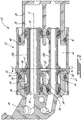
Fig. 2 is a longitudinal cross-section view of the transfer tube assembly illustrating a pair of transfer tubes having respective shoulders engageable with a stopper for limiting axial movement of the transfer tubes relative to the adjoining components, the shoulders having a geometry configured to generate axially opposing axial forces when contacting the surrounding chamfered surface of respective mating bores; -
Fig. 3 is a cross-section view taken along line 3-3 ofFig. 2 ; -
Fig. 4 is an isometric view illustrating the overlapping portion of the transfer tube shoulders and the stopper; and -
Fig. 5 is a schematic cross-section view of a gas turbine engine in which the transfer tube assembly may be installed. -
Fig. 1 illustrates atransfer tube assembly 20 comprising atransfer tube unit 22 fluidly connecting afirst component 24 to asecond component 26. According to the illustrated embodiment, thefirst component 24 is an inlet nozzle of a gas turbine engine fuel manifold and thesecond component 26 is a fuel manifold adapter. According to another embodiment, thetransfer tube unit 22 could be integrated to a lubricant line, such as an oil feed line of a bearing housing of a gas turbine engine. The present disclosure, however, is not limited to gas turbine engines. Indeed, it is understood that thetransfer tube unit 22 could be used to fluidly connect various types of components in a wide variety of environments. - As shown in
Fig. 2 , thetransfer tube unit 22 comprises at least onetransfer tube 28a (e.g. a primary fuel transfer tube) having a rigid tubular body extending along a longitudinal axis A from afirst end 30 to asecond end 32. The tubular body may be made of various materials depending its intended environment of use. For instance, when used as part of a fuel manifold of a gas turbine engine, thetransfer tube 28a may be made out of stainless steel. Thefirst end 30 oftube 28a is sealingly slidably received in afirst bore 34 of thefirst component 24, whereas thesecond end 32 of the tube is sealingly slidably received in asecond bore 36 of thesecond component 26. Seals, such as O-rings 38, may be provided at the first andsecond ends transfer tube 28a for sealing engagement in the bore of the first andsecond components rings 38 may be removably mounted in corresponding annular seats integrally formed in the outer cylindrical surface of thetransfer tube 28a. - According to some embodiments, the
transfer tube unit 22 further comprises adrain sleeve 40 extending between and sealingly connected at opposite ends to the first andsecond components Fig. 2 , O-rings 42 may be mounted to the adjacent ends of the first andsecond components sleeve 40, thereby providing for the creation of a sealedcavity 44 around the at least onetransfer tube 28a. The sealedcavity 44 is configured to trap any fluid that may leak over O-rings 38 at the interface between thetransfer tube 28a and the bore of the first andsecond components cavity 44 for returning any collected fluid into the fluid system. In addition to its sealing function, thesleeve 40 may act has an axial retention feature for limiting back and forth movement of thetransfer tube 28a relative to the first andsecond components drain sleeve 40 may include astopper 48 for engagement with acorresponding shoulder 50 projecting outwardly from an outer surface of the at least onetransfer tube 28a. According to some embodiments, thestopper 48 is provided in the form of an annular inner shoulder projecting from the inner surface of thesleeve 40. Still according to some embodiments, thestopper 48 may be engaged in agroove 52 defined in theshoulder 50 of thetransfer tube 28a to limit the axial movement of thetransfer tube 28a relative to the first andsecond components second components sleeve 40 may be secured in position by securely attaching the sleeve to an adjacent stationary structure (not shown). The person skilled in the art will appreciate that the axial retaining function can be done via a stopper interfacing with thesleeve 40; for instance, in either thesleeve 40 or first orsecond component grooves 52 forstoppers 48 can be provided which can securely engage thesleeve 40 and limit travel. As shown inFigs. 1 ,3 and4 , this can be done via aflange 54 extending from an outer surface of thesleeve 40. For instance, holes can be provided in theflange 54 to allow thesleeve 40 to be securely bolted in position. - According to some embodiments, the stopper providing the desired axial retention function could be integrated to a component other than the
drain sleeve 40 and the drain sleeve could be omitted. For instance, the stopper could form part of an adjacent stationary structure or it could be provided on the first orsecond component - According to the exemplary embodiment shown in
Fig. 2 , thetransfer tube shoulder 50 has a conical bore abutment/engaging surface 54 tapering in an axial direction towards thefirst end 30 of thetransfer tube 28a. Theconical abutment surface 54 defines a slope having an axial component and a radial component relative to the longitudinal axis A. As can be appreciated fromFig. 2 , theconical abutment surface 54 is received in the entry portion of thefirst bore 34 of thefirst component 24. More particularly, theconical abutment surface 54 is disposed in facing relation with the chamferededge surface 56 circumscribing the entry portion of thefirst bore 34. Still according to the illustrated embodiment, thesurfaces surfaces annular gap 58. Thenominal gap 58 allows for potential misalignment between the first andsecond components gap 58 will close and the twosurfaces mating surfaces transfer tube 28a to slide at an extremum. This reduces the risk of thetransfer tube shoulder 54 interfering with the mating bore in addition to helping sliding movement between thetransfer tube 28a and thefirst component 24. The twoconical contact surfaces surfaces nominal gap 58 can be greater due to the similar geometric profile ofsurfaces second components surfaces transfer tube 28a. For instance, alternative embodiments entail any geometric shape or cone angles which result in opposing axial components in the transfer tube and which would reduce the resistance to axial sliding in the event of a radial/tangential misalignment. - In that regard,
Fig. 2 illustrates an example of asecond transfer tube 28b (e.g. a secondary fuel transfer tube) having a rounded shoulder profile. According to this alternative, the bore engagement surface 54' of the transfer tube shoulder 50' extends along a curve having axial and radial components. Still according to this alternative, the curved surface 54' is engageable with the conical surface 56' (i.e. the chamfered edge surface) circumscribing the entry of the associated bore 34' in thefirst component 24. The curve of the bore engagement surface 54' is configured to maximise the contact surface between the wall of thebore 34' and thetransfer tube 28b. This promotes more uniform load distribution by avoiding a single point of load transfer between the transfer tube shoulder 50' and the wall of thebore 34' in the event surface 54' contacts surface 56'. The other features of thesecond transfer 28b are similar to thefirst transfer tube 28a and will thus not be herein repeated for brevity. - For embodiments where the
transfer tube unit 22 comprises more than one transfer tubes, it is understood that the transfer tubes may have similar or different shoulder profiles. - The
transfer tube assembly 20 is assembled by first installing the first andsecond transfer tubes drain sleeve 40. Thetubes sleeve 40 and engaged in respective seats formed in the inner shoulder acting as thestopper 48. As shown inFigs. 3 and4 , thestopper 48 is engaged in overlapping relation withshoulders 50, 50' to limit axial movement of thetransfer tubes second components Fig. 2 . The assembly is completed by securing thedrain sleeve 40 in position. This may be achieved by securely engaging thestopper 48 with respect to thegroove 52 of thesleeve 40 or first orsecond component -
Fig. 5 illustrates agas turbine engine 10 with which thetransfer tube assembly 20 may be configured. According to the illustrated example, theengine 10 is a turboshaft engine generally comprising in serial flow communication acompressor 12 for pressurizing the air, acombustor 16 in which the compressed air is mixed with fuel and ignited for generating an annular stream of hot combustion gases, and aturbine section 18 for extracting energy from the combustion gases. Thetransfer tube assembly 20 may be used in various sections of theengine 10. For instance, it may be used in the engine hot section at location L1 as part of the fuel manifold of thecombustor 16. Alternatively, it can be used in the cold section of the engine at location L2 as part of a fluid carrying transfer tube system between engine cases. In addition, it is understood that thetransfer tube assembly 20 may be included in various engines other than the one described above as well as in other types of equipment. For instance, it could be used in an aircraft engine, such as a turbofan, a turboprop, a hybrid engine, a compounded engine or an auxiliary power unit to name a few. - The embodiments described in this document provide non-limiting examples of possible implementations of the present technology. Upon review of the present disclosure, a person of ordinary skill in the art will recognize that changes may be made to the embodiments described herein without departing from the scope of the present technology. Indeed, various modifications could be implemented by a person of ordinary skill in the art in view of the present disclosure, which modifications would be within the scope of the present technology.
Claims (15)
- A transfer tube assembly (20) for an aircraft engine (10), comprising:a first component (24) having a first bore (34);a second component (26) having a second bore (36);a transfer tube (28a, 28b) fluidly connecting the first component (24) to the second component (26), the transfer tube (28a, 28b) extending along a longitudinal axis (A) from a first end (30) to a second end (32), the first end (30) sealingly slidably received in the first bore (34) of the first component (30) and the second end (32) sealingly slidably received in the second bore (36) of the second component (26), the transfer tube (28a, 28b) having a shoulder (50) projecting from an outer surface thereof and engageable with a corresponding stopper (48) for limiting axial movement of the transfer tube (28a, 28b) relative to the first and second components (24, 26), the shoulder (50) having an abutment surface (54) facing a corresponding bore surface (56) of the first bore (34) of the first component (30), the abutment surface (54) and the bore surface (56) generating opposing axial forces along the longitudinal axis (A) in response to the abutment surface (54) and the bore surface (56) contacting each other.
- The transfer tube assembly (20) of claim 1, wherein the abutment surface (54) and the bore surface (56) extend around the longitudinal axis (A), and the abutment surface (54) and the bore surface (56) have a contact interface, the contact interface having an axial component relative to the longitudinal axis (A).
- The transfer tube assembly (20) of claim 1 or 2, wherein at least one of the abutment surface (54) and the bore surface (56) is conical.
- The transfer tube assembly (20) of claim 3, wherein both the abutment surface (54) and the bore surface (56) are conical.
- The transfer tube assembly (20) of claim 3, wherein the abutment surface (54) is curved when viewed in a longitudinal cross-section of the transfer tube (28a, 28b), and the bore surface (56) is conical.
- The transfer tube assembly (20) of any preceding claim, wherein each of the abutment surface (54) and the bore surface (56) defines a slope relative to the longitudinal axis (A) when viewed in an axially extending cross-section plane, the slope having an axial component along the longitudinal axis (A) of the transfer tube (28a, 28b).
- The transfer tube assembly (20) of any preceding claim, further comprising a drain sleeve (40) extending between and sealingly connected at opposite ends to the first and second components (24, 26), the transfer tube (28a, 28b) disposed in the drain sleeve (40), and wherein the stopper (48) includes an inner shoulder projecting from an inner surface of the drain sleeve (40) for engagement with the shoulder (50) of the transfer tube (28a, 28b).
- The transfer tube assembly (20) of claim 7, wherein the drain sleeve (40) has a flange (54) extending from an outer surface thereof for attachment to an adjacent stationary structure.
- The transfer tube assembly (20) of any preceding claim, wherein the bore surface (56) of the first bore (34) includes a chamfered edge surface (56) at an entry of the first bore (34), the transfer tube (28a, 28b) carries a seal (38) at the first end (30) thereof, and the shoulder (50) is axially spaced from the seal (38) and received in the entry of the first bore (34) for engagement with the chamfered edge surface (56).
- The transfer tube assembly (20) of any preceding claim, wherein the abutment surface (54) of the shoulder (50) includes a conical surface, and the bore surface (56) of the first bore (34) of the first component (24) includes a chamfered edge surface, the conical surface (54) and the chamfered edge surface (56) spaced by a nominal gap (58).
- The transfer tube assembly (20) of claim 10, wherein the conical surface (54) and the chamfered edge surface (56) have the same cone angle.
- The transfer tube assembly (20) of claim 10 or 11, wherein the conical surface (54) and the chamfered edge surface (56) are configured to generate opposing axial reaction forces relative to the longitudinal axis (A) when pushed against one another.
- The transfer tube assembly (20) of any preceding claim, wherein the abutment surface (54) of the shoulder (50) is a bore engaging surface (54) facing the bore surface (56) of the first component (24), the bore engaging surface (54) and the bore surface (56) defining a contact interface having an axial component and a radial component relative to the longitudinal axis (A).
- The transfer tube assembly (20) of claim 13, wherein the bore surface (56) is a chamfered edge surface (56) at the entry of the bore (34), and wherein the bore engaging surface (54) is received in the entry portion of the bore (34), the chamfered edge surface (56) extending annularly around the bore engaging surface (54).
- The transfer tube assembly (20) of claim 13 or 14, wherein the bore engaging surface (54) is curved.
Applications Claiming Priority (1)
| Application Number | Priority Date | Filing Date | Title |
|---|---|---|---|
| US17/246,836 US11719159B2 (en) | 2021-05-03 | 2021-05-03 | Transfer tube assembly |
Publications (2)
| Publication Number | Publication Date |
|---|---|
| EP4086496A1 true EP4086496A1 (en) | 2022-11-09 |
| EP4086496B1 EP4086496B1 (en) | 2024-06-26 |
Family
ID=81580020
Family Applications (1)
| Application Number | Title | Priority Date | Filing Date |
|---|---|---|---|
| EP22171445.4A Active EP4086496B1 (en) | 2021-05-03 | 2022-05-03 | Transfer tube assembly |
Country Status (3)
| Country | Link |
|---|---|
| US (1) | US11719159B2 (en) |
| EP (1) | EP4086496B1 (en) |
| CA (1) | CA3157077A1 (en) |
Families Citing this family (1)
| Publication number | Priority date | Publication date | Assignee | Title |
|---|---|---|---|---|
| US12241416B2 (en) | 2022-07-04 | 2025-03-04 | Pratt & Whitney Canada Corp. | Adaptor for a fuel system of an aircraft engine |
Citations (3)
| Publication number | Priority date | Publication date | Assignee | Title |
|---|---|---|---|---|
| US4066281A (en) * | 1976-07-16 | 1978-01-03 | Bonis John C De | Porsche automobile oil drain replacement tube |
| CA2714826C (en) * | 2009-10-01 | 2014-07-22 | Pratt & Whitney Canada Corp. | Bleed air transfer tube |
| DE102016226019A1 (en) * | 2016-12-22 | 2018-06-28 | Mahle International Gmbh | Coupling element of a crankcase ventilation device |
Family Cites Families (12)
| Publication number | Priority date | Publication date | Assignee | Title |
|---|---|---|---|---|
| US420220A (en) * | 1890-01-28 | Island | ||
| FR2203026B1 (en) * | 1972-10-12 | 1976-01-30 | Europ De Propulsion Fr | |
| US3873134A (en) * | 1973-01-04 | 1975-03-25 | Michael Sammaritano | Apparatus for joining preformed conduits |
| US4482171A (en) * | 1979-01-25 | 1984-11-13 | Campbell Joseph K | Pipe stress/strain neutralizers |
| FR2639702B1 (en) * | 1988-11-25 | 1991-03-22 | Aerospatiale | WATERPROOF AND REMOVABLE CONNECTION DEVICE FOR TWO TUBES, PARTICULARLY FOR FUEL TRANSFER INSTALLATION |
| US5106129A (en) * | 1990-10-09 | 1992-04-21 | Delaware Capital Formation, Inc. | Flexible coupling for transferring a fluid between two fluid conduits |
| US5261240A (en) | 1992-09-23 | 1993-11-16 | General Electric Company | Fuel shroud system with spherical ferrule/drain can interface |
| US20040032123A1 (en) * | 2002-08-13 | 2004-02-19 | Li-Yun Chu | Angle-adjustable connector |
| FR2934027B1 (en) * | 2008-07-18 | 2011-03-25 | Thales Sa | FLOW CONTROL DEVICE AND USE OF SUCH A DEVICE |
| US8205643B2 (en) | 2008-10-16 | 2012-06-26 | Woodward, Inc. | Multi-tubular fluid transfer conduit |
| US9797313B2 (en) | 2014-01-16 | 2017-10-24 | Pratt & Whitney Canada Corp. | Internal manifold with fuel inlet |
| US12123314B2 (en) * | 2020-10-27 | 2024-10-22 | Pratt & Whitney Canada Corp. | Service tube assembly for a gas turbine engine |
-
2021
- 2021-05-03 US US17/246,836 patent/US11719159B2/en active Active
-
2022
- 2022-04-22 CA CA3157077A patent/CA3157077A1/en active Pending
- 2022-05-03 EP EP22171445.4A patent/EP4086496B1/en active Active
Patent Citations (3)
| Publication number | Priority date | Publication date | Assignee | Title |
|---|---|---|---|---|
| US4066281A (en) * | 1976-07-16 | 1978-01-03 | Bonis John C De | Porsche automobile oil drain replacement tube |
| CA2714826C (en) * | 2009-10-01 | 2014-07-22 | Pratt & Whitney Canada Corp. | Bleed air transfer tube |
| DE102016226019A1 (en) * | 2016-12-22 | 2018-06-28 | Mahle International Gmbh | Coupling element of a crankcase ventilation device |
Also Published As
| Publication number | Publication date |
|---|---|
| US20220349344A1 (en) | 2022-11-03 |
| CA3157077A1 (en) | 2022-11-03 |
| EP4086496B1 (en) | 2024-06-26 |
| US11719159B2 (en) | 2023-08-08 |
Similar Documents
| Publication | Publication Date | Title |
|---|---|---|
| EP1561990B1 (en) | Quick connector for high pressure applications | |
| US7000406B2 (en) | Gas turbine combustor sliding joint | |
| US9506403B2 (en) | Fastener | |
| CN103109044B (en) | Turbine jet engine ventilation duct, the method for this ventilation duct is installed and is provided with the turbine jet engine of this ventilation duct | |
| CN100386556C (en) | Female coupling element and quick-connect coupling incorporating such an element | |
| US20110241341A1 (en) | Exhaust pipe for a motor vehicle and exhaust system | |
| US8490409B2 (en) | Bleed air transfer tube | |
| US10145256B2 (en) | Aircraft propulsion system seal assembly with spring seal element and compliant seal element | |
| EP1887270A1 (en) | Assembly including a seal | |
| EP3597869B1 (en) | Sealing configuration for a transfer tube assembly to reduce air leakage | |
| EP3992434B1 (en) | Service tube assembly for a gas turbine engine | |
| US7344166B2 (en) | Quick connector for high pressure applications | |
| US4201048A (en) | Exhaust system connector | |
| EP4086496B1 (en) | Transfer tube assembly | |
| EP2816268B1 (en) | High pressure check valve flange joint | |
| US11125095B2 (en) | Sliding seal | |
| US7845649B2 (en) | Methods and apparatus to facilitate sealing high pressure joints | |
| EP3705687A1 (en) | Slider seal | |
| US20060266049A1 (en) | Expansion joint and method of assembling same | |
| US11352896B2 (en) | Tube assembly for a gas turbine engine | |
| EP4306773B1 (en) | Service tube locking device | |
| US20190003367A1 (en) | Lobed exhaust manifold slip joint | |
| US12012872B1 (en) | Service tube locking device | |
| CN116917668B (en) | Subassembly including means for compensating for differential expansion | |
| US20220145829A1 (en) | Positive retention expansion joints |
Legal Events
| Date | Code | Title | Description |
|---|---|---|---|
| PUAI | Public reference made under article 153(3) epc to a published international application that has entered the european phase |
Free format text: ORIGINAL CODE: 0009012 |
|
| STAA | Information on the status of an ep patent application or granted ep patent |
Free format text: STATUS: THE APPLICATION HAS BEEN PUBLISHED |
|
| AK | Designated contracting states |
Kind code of ref document: A1 Designated state(s): AL AT BE BG CH CY CZ DE DK EE ES FI FR GB GR HR HU IE IS IT LI LT LU LV MC MK MT NL NO PL PT RO RS SE SI SK SM TR |
|
| STAA | Information on the status of an ep patent application or granted ep patent |
Free format text: STATUS: REQUEST FOR EXAMINATION WAS MADE |
|
| 17P | Request for examination filed |
Effective date: 20230509 |
|
| RBV | Designated contracting states (corrected) |
Designated state(s): AL AT BE BG CH CY CZ DE DK EE ES FI FR GB GR HR HU IE IS IT LI LT LU LV MC MK MT NL NO PL PT RO RS SE SI SK SM TR |
|
| GRAP | Despatch of communication of intention to grant a patent |
Free format text: ORIGINAL CODE: EPIDOSNIGR1 |
|
| STAA | Information on the status of an ep patent application or granted ep patent |
Free format text: STATUS: GRANT OF PATENT IS INTENDED |
|
| RIC1 | Information provided on ipc code assigned before grant |
Ipc: F16L 39/04 20060101ALI20231208BHEP Ipc: F16L 51/00 20060101ALI20231208BHEP Ipc: F16L 27/12 20060101AFI20231208BHEP |
|
| INTG | Intention to grant announced |
Effective date: 20240104 |
|
| GRAS | Grant fee paid |
Free format text: ORIGINAL CODE: EPIDOSNIGR3 |
|
| GRAA | (expected) grant |
Free format text: ORIGINAL CODE: 0009210 |
|
| STAA | Information on the status of an ep patent application or granted ep patent |
Free format text: STATUS: THE PATENT HAS BEEN GRANTED |
|
| AK | Designated contracting states |
Kind code of ref document: B1 Designated state(s): AL AT BE BG CH CY CZ DE DK EE ES FI FR GB GR HR HU IE IS IT LI LT LU LV MC MK MT NL NO PL PT RO RS SE SI SK SM TR |
|
| REG | Reference to a national code |
Ref country code: GB Ref legal event code: FG4D |
|
| REG | Reference to a national code |
Ref country code: CH Ref legal event code: EP |
|
| REG | Reference to a national code |
Ref country code: DE Ref legal event code: R096 Ref document number: 602022004103 Country of ref document: DE |
|
| PG25 | Lapsed in a contracting state [announced via postgrant information from national office to epo] |
Ref country code: BG Free format text: LAPSE BECAUSE OF FAILURE TO SUBMIT A TRANSLATION OF THE DESCRIPTION OR TO PAY THE FEE WITHIN THE PRESCRIBED TIME-LIMIT Effective date: 20240626 |
|
| PG25 | Lapsed in a contracting state [announced via postgrant information from national office to epo] |
Ref country code: FI Free format text: LAPSE BECAUSE OF FAILURE TO SUBMIT A TRANSLATION OF THE DESCRIPTION OR TO PAY THE FEE WITHIN THE PRESCRIBED TIME-LIMIT Effective date: 20240626 Ref country code: HR Free format text: LAPSE BECAUSE OF FAILURE TO SUBMIT A TRANSLATION OF THE DESCRIPTION OR TO PAY THE FEE WITHIN THE PRESCRIBED TIME-LIMIT Effective date: 20240626 |
|
| REG | Reference to a national code |
Ref country code: LT Ref legal event code: MG9D |
|
| PG25 | Lapsed in a contracting state [announced via postgrant information from national office to epo] |
Ref country code: GR Free format text: LAPSE BECAUSE OF FAILURE TO SUBMIT A TRANSLATION OF THE DESCRIPTION OR TO PAY THE FEE WITHIN THE PRESCRIBED TIME-LIMIT Effective date: 20240927 |
|
| PG25 | Lapsed in a contracting state [announced via postgrant information from national office to epo] |
Ref country code: LV Free format text: LAPSE BECAUSE OF FAILURE TO SUBMIT A TRANSLATION OF THE DESCRIPTION OR TO PAY THE FEE WITHIN THE PRESCRIBED TIME-LIMIT Effective date: 20240626 |
|
| REG | Reference to a national code |
Ref country code: NL Ref legal event code: MP Effective date: 20240626 |
|
| PG25 | Lapsed in a contracting state [announced via postgrant information from national office to epo] |
Ref country code: NO Free format text: LAPSE BECAUSE OF FAILURE TO SUBMIT A TRANSLATION OF THE DESCRIPTION OR TO PAY THE FEE WITHIN THE PRESCRIBED TIME-LIMIT Effective date: 20240926 Ref country code: LV Free format text: LAPSE BECAUSE OF FAILURE TO SUBMIT A TRANSLATION OF THE DESCRIPTION OR TO PAY THE FEE WITHIN THE PRESCRIBED TIME-LIMIT Effective date: 20240626 Ref country code: HR Free format text: LAPSE BECAUSE OF FAILURE TO SUBMIT A TRANSLATION OF THE DESCRIPTION OR TO PAY THE FEE WITHIN THE PRESCRIBED TIME-LIMIT Effective date: 20240626 Ref country code: GR Free format text: LAPSE BECAUSE OF FAILURE TO SUBMIT A TRANSLATION OF THE DESCRIPTION OR TO PAY THE FEE WITHIN THE PRESCRIBED TIME-LIMIT Effective date: 20240927 Ref country code: FI Free format text: LAPSE BECAUSE OF FAILURE TO SUBMIT A TRANSLATION OF THE DESCRIPTION OR TO PAY THE FEE WITHIN THE PRESCRIBED TIME-LIMIT Effective date: 20240626 Ref country code: BG Free format text: LAPSE BECAUSE OF FAILURE TO SUBMIT A TRANSLATION OF THE DESCRIPTION OR TO PAY THE FEE WITHIN THE PRESCRIBED TIME-LIMIT Effective date: 20240626 Ref country code: RS Free format text: LAPSE BECAUSE OF FAILURE TO SUBMIT A TRANSLATION OF THE DESCRIPTION OR TO PAY THE FEE WITHIN THE PRESCRIBED TIME-LIMIT Effective date: 20240926 |
|
| PG25 | Lapsed in a contracting state [announced via postgrant information from national office to epo] |
Ref country code: NL Free format text: LAPSE BECAUSE OF FAILURE TO SUBMIT A TRANSLATION OF THE DESCRIPTION OR TO PAY THE FEE WITHIN THE PRESCRIBED TIME-LIMIT Effective date: 20240626 |
|
| REG | Reference to a national code |
Ref country code: AT Ref legal event code: MK05 Ref document number: 1697974 Country of ref document: AT Kind code of ref document: T Effective date: 20240626 |
|
| PG25 | Lapsed in a contracting state [announced via postgrant information from national office to epo] |
Ref country code: NL Free format text: LAPSE BECAUSE OF FAILURE TO SUBMIT A TRANSLATION OF THE DESCRIPTION OR TO PAY THE FEE WITHIN THE PRESCRIBED TIME-LIMIT Effective date: 20240626 |
|
| PG25 | Lapsed in a contracting state [announced via postgrant information from national office to epo] |
Ref country code: PT Free format text: LAPSE BECAUSE OF FAILURE TO SUBMIT A TRANSLATION OF THE DESCRIPTION OR TO PAY THE FEE WITHIN THE PRESCRIBED TIME-LIMIT Effective date: 20241028 |
|
| PG25 | Lapsed in a contracting state [announced via postgrant information from national office to epo] |
Ref country code: PT Free format text: LAPSE BECAUSE OF FAILURE TO SUBMIT A TRANSLATION OF THE DESCRIPTION OR TO PAY THE FEE WITHIN THE PRESCRIBED TIME-LIMIT Effective date: 20241028 |
|
| PG25 | Lapsed in a contracting state [announced via postgrant information from national office to epo] |
Ref country code: PL Free format text: LAPSE BECAUSE OF FAILURE TO SUBMIT A TRANSLATION OF THE DESCRIPTION OR TO PAY THE FEE WITHIN THE PRESCRIBED TIME-LIMIT Effective date: 20240626 |
|
| PG25 | Lapsed in a contracting state [announced via postgrant information from national office to epo] |
Ref country code: EE Free format text: LAPSE BECAUSE OF FAILURE TO SUBMIT A TRANSLATION OF THE DESCRIPTION OR TO PAY THE FEE WITHIN THE PRESCRIBED TIME-LIMIT Effective date: 20240626 |
|
| PG25 | Lapsed in a contracting state [announced via postgrant information from national office to epo] |
Ref country code: IS Free format text: LAPSE BECAUSE OF FAILURE TO SUBMIT A TRANSLATION OF THE DESCRIPTION OR TO PAY THE FEE WITHIN THE PRESCRIBED TIME-LIMIT Effective date: 20241026 Ref country code: AT Free format text: LAPSE BECAUSE OF FAILURE TO SUBMIT A TRANSLATION OF THE DESCRIPTION OR TO PAY THE FEE WITHIN THE PRESCRIBED TIME-LIMIT Effective date: 20240626 |
|
| PG25 | Lapsed in a contracting state [announced via postgrant information from national office to epo] |
Ref country code: CZ Free format text: LAPSE BECAUSE OF FAILURE TO SUBMIT A TRANSLATION OF THE DESCRIPTION OR TO PAY THE FEE WITHIN THE PRESCRIBED TIME-LIMIT Effective date: 20240626 |
|
| PG25 | Lapsed in a contracting state [announced via postgrant information from national office to epo] |
Ref country code: RO Free format text: LAPSE BECAUSE OF FAILURE TO SUBMIT A TRANSLATION OF THE DESCRIPTION OR TO PAY THE FEE WITHIN THE PRESCRIBED TIME-LIMIT Effective date: 20240626 Ref country code: SK Free format text: LAPSE BECAUSE OF FAILURE TO SUBMIT A TRANSLATION OF THE DESCRIPTION OR TO PAY THE FEE WITHIN THE PRESCRIBED TIME-LIMIT Effective date: 20240626 |
|
| PG25 | Lapsed in a contracting state [announced via postgrant information from national office to epo] |
Ref country code: SM Free format text: LAPSE BECAUSE OF FAILURE TO SUBMIT A TRANSLATION OF THE DESCRIPTION OR TO PAY THE FEE WITHIN THE PRESCRIBED TIME-LIMIT Effective date: 20240626 Ref country code: ES Free format text: LAPSE BECAUSE OF FAILURE TO SUBMIT A TRANSLATION OF THE DESCRIPTION OR TO PAY THE FEE WITHIN THE PRESCRIBED TIME-LIMIT Effective date: 20240626 |
|
| PG25 | Lapsed in a contracting state [announced via postgrant information from national office to epo] |
Ref country code: SM Free format text: LAPSE BECAUSE OF FAILURE TO SUBMIT A TRANSLATION OF THE DESCRIPTION OR TO PAY THE FEE WITHIN THE PRESCRIBED TIME-LIMIT Effective date: 20240626 Ref country code: SK Free format text: LAPSE BECAUSE OF FAILURE TO SUBMIT A TRANSLATION OF THE DESCRIPTION OR TO PAY THE FEE WITHIN THE PRESCRIBED TIME-LIMIT Effective date: 20240626 Ref country code: RO Free format text: LAPSE BECAUSE OF FAILURE TO SUBMIT A TRANSLATION OF THE DESCRIPTION OR TO PAY THE FEE WITHIN THE PRESCRIBED TIME-LIMIT Effective date: 20240626 Ref country code: PL Free format text: LAPSE BECAUSE OF FAILURE TO SUBMIT A TRANSLATION OF THE DESCRIPTION OR TO PAY THE FEE WITHIN THE PRESCRIBED TIME-LIMIT Effective date: 20240626 Ref country code: IS Free format text: LAPSE BECAUSE OF FAILURE TO SUBMIT A TRANSLATION OF THE DESCRIPTION OR TO PAY THE FEE WITHIN THE PRESCRIBED TIME-LIMIT Effective date: 20241026 Ref country code: ES Free format text: LAPSE BECAUSE OF FAILURE TO SUBMIT A TRANSLATION OF THE DESCRIPTION OR TO PAY THE FEE WITHIN THE PRESCRIBED TIME-LIMIT Effective date: 20240626 Ref country code: EE Free format text: LAPSE BECAUSE OF FAILURE TO SUBMIT A TRANSLATION OF THE DESCRIPTION OR TO PAY THE FEE WITHIN THE PRESCRIBED TIME-LIMIT Effective date: 20240626 Ref country code: CZ Free format text: LAPSE BECAUSE OF FAILURE TO SUBMIT A TRANSLATION OF THE DESCRIPTION OR TO PAY THE FEE WITHIN THE PRESCRIBED TIME-LIMIT Effective date: 20240626 Ref country code: AT Free format text: LAPSE BECAUSE OF FAILURE TO SUBMIT A TRANSLATION OF THE DESCRIPTION OR TO PAY THE FEE WITHIN THE PRESCRIBED TIME-LIMIT Effective date: 20240626 |
|
| PG25 | Lapsed in a contracting state [announced via postgrant information from national office to epo] |
Ref country code: IT Free format text: LAPSE BECAUSE OF FAILURE TO SUBMIT A TRANSLATION OF THE DESCRIPTION OR TO PAY THE FEE WITHIN THE PRESCRIBED TIME-LIMIT Effective date: 20240626 |
|
| REG | Reference to a national code |
Ref country code: DE Ref legal event code: R097 Ref document number: 602022004103 Country of ref document: DE |
|
| PG25 | Lapsed in a contracting state [announced via postgrant information from national office to epo] |
Ref country code: DK Free format text: LAPSE BECAUSE OF FAILURE TO SUBMIT A TRANSLATION OF THE DESCRIPTION OR TO PAY THE FEE WITHIN THE PRESCRIBED TIME-LIMIT Effective date: 20240626 |
|
| PLBE | No opposition filed within time limit |
Free format text: ORIGINAL CODE: 0009261 |
|
| STAA | Information on the status of an ep patent application or granted ep patent |
Free format text: STATUS: NO OPPOSITION FILED WITHIN TIME LIMIT |
|
| 26N | No opposition filed |
Effective date: 20250327 |
|
| PGFP | Annual fee paid to national office [announced via postgrant information from national office to epo] |
Ref country code: DE Payment date: 20250423 Year of fee payment: 4 |
|
| PGFP | Annual fee paid to national office [announced via postgrant information from national office to epo] |
Ref country code: FR Payment date: 20250423 Year of fee payment: 4 |
|
| PG25 | Lapsed in a contracting state [announced via postgrant information from national office to epo] |
Ref country code: SE Free format text: LAPSE BECAUSE OF FAILURE TO SUBMIT A TRANSLATION OF THE DESCRIPTION OR TO PAY THE FEE WITHIN THE PRESCRIBED TIME-LIMIT Effective date: 20240626 |
|
| REG | Reference to a national code |
Ref country code: CH Ref legal event code: H13 Free format text: ST27 STATUS EVENT CODE: U-0-0-H10-H13 (AS PROVIDED BY THE NATIONAL OFFICE) Effective date: 20251223 |
|
| PG25 | Lapsed in a contracting state [announced via postgrant information from national office to epo] |
Ref country code: LU Free format text: LAPSE BECAUSE OF NON-PAYMENT OF DUE FEES Effective date: 20250503 |
|
| PG25 | Lapsed in a contracting state [announced via postgrant information from national office to epo] |
Ref country code: CH Free format text: LAPSE BECAUSE OF NON-PAYMENT OF DUE FEES Effective date: 20250531 |
|
| REG | Reference to a national code |
Ref country code: BE Ref legal event code: MM Effective date: 20250531 |
|
| PG25 | Lapsed in a contracting state [announced via postgrant information from national office to epo] |
Ref country code: MC Free format text: LAPSE BECAUSE OF FAILURE TO SUBMIT A TRANSLATION OF THE DESCRIPTION OR TO PAY THE FEE WITHIN THE PRESCRIBED TIME-LIMIT Effective date: 20240626 |
|
| PG25 | Lapsed in a contracting state [announced via postgrant information from national office to epo] |
Ref country code: IE Free format text: LAPSE BECAUSE OF NON-PAYMENT OF DUE FEES Effective date: 20250503 |
|
| PG25 | Lapsed in a contracting state [announced via postgrant information from national office to epo] |
Ref country code: BE Free format text: LAPSE BECAUSE OF NON-PAYMENT OF DUE FEES Effective date: 20250531 |