EP4086489A1 - Three-way valve and anaesthesia machine - Google Patents
Three-way valve and anaesthesia machine Download PDFInfo
- Publication number
- EP4086489A1 EP4086489A1 EP19958322.0A EP19958322A EP4086489A1 EP 4086489 A1 EP4086489 A1 EP 4086489A1 EP 19958322 A EP19958322 A EP 19958322A EP 4086489 A1 EP4086489 A1 EP 4086489A1
- Authority
- EP
- European Patent Office
- Prior art keywords
- valve
- rod
- way valve
- channel
- core assembly
- Prior art date
- Legal status (The legal status is an assumption and is not a legal conclusion. Google has not performed a legal analysis and makes no representation as to the accuracy of the status listed.)
- Pending
Links
Images


Classifications
-
- F—MECHANICAL ENGINEERING; LIGHTING; HEATING; WEAPONS; BLASTING
- F16—ENGINEERING ELEMENTS AND UNITS; GENERAL MEASURES FOR PRODUCING AND MAINTAINING EFFECTIVE FUNCTIONING OF MACHINES OR INSTALLATIONS; THERMAL INSULATION IN GENERAL
- F16K—VALVES; TAPS; COCKS; ACTUATING-FLOATS; DEVICES FOR VENTING OR AERATING
- F16K11/00—Multiple-way valves, e.g. mixing valves; Pipe fittings incorporating such valves
- F16K11/02—Multiple-way valves, e.g. mixing valves; Pipe fittings incorporating such valves with all movable sealing faces moving as one unit
- F16K11/04—Multiple-way valves, e.g. mixing valves; Pipe fittings incorporating such valves with all movable sealing faces moving as one unit comprising only lift valves
- F16K11/044—Multiple-way valves, e.g. mixing valves; Pipe fittings incorporating such valves with all movable sealing faces moving as one unit comprising only lift valves with movable valve members positioned between valve seats
-
- A—HUMAN NECESSITIES
- A61—MEDICAL OR VETERINARY SCIENCE; HYGIENE
- A61M—DEVICES FOR INTRODUCING MEDIA INTO, OR ONTO, THE BODY; DEVICES FOR TRANSDUCING BODY MEDIA OR FOR TAKING MEDIA FROM THE BODY; DEVICES FOR PRODUCING OR ENDING SLEEP OR STUPOR
- A61M16/00—Devices for influencing the respiratory system of patients by gas treatment, e.g. ventilators; Tracheal tubes
- A61M16/01—Devices for influencing the respiratory system of patients by gas treatment, e.g. ventilators; Tracheal tubes specially adapted for anaesthetising
-
- A—HUMAN NECESSITIES
- A61—MEDICAL OR VETERINARY SCIENCE; HYGIENE
- A61M—DEVICES FOR INTRODUCING MEDIA INTO, OR ONTO, THE BODY; DEVICES FOR TRANSDUCING BODY MEDIA OR FOR TAKING MEDIA FROM THE BODY; DEVICES FOR PRODUCING OR ENDING SLEEP OR STUPOR
- A61M16/00—Devices for influencing the respiratory system of patients by gas treatment, e.g. ventilators; Tracheal tubes
- A61M16/021—Devices for influencing the respiratory system of patients by gas treatment, e.g. ventilators; Tracheal tubes operated by electrical means
- A61M16/022—Control means therefor
-
- A—HUMAN NECESSITIES
- A61—MEDICAL OR VETERINARY SCIENCE; HYGIENE
- A61M—DEVICES FOR INTRODUCING MEDIA INTO, OR ONTO, THE BODY; DEVICES FOR TRANSDUCING BODY MEDIA OR FOR TAKING MEDIA FROM THE BODY; DEVICES FOR PRODUCING OR ENDING SLEEP OR STUPOR
- A61M16/00—Devices for influencing the respiratory system of patients by gas treatment, e.g. ventilators; Tracheal tubes
- A61M16/20—Valves specially adapted to medical respiratory devices
- A61M16/201—Controlled valves
- A61M16/202—Controlled valves electrically actuated
-
- F—MECHANICAL ENGINEERING; LIGHTING; HEATING; WEAPONS; BLASTING
- F16—ENGINEERING ELEMENTS AND UNITS; GENERAL MEASURES FOR PRODUCING AND MAINTAINING EFFECTIVE FUNCTIONING OF MACHINES OR INSTALLATIONS; THERMAL INSULATION IN GENERAL
- F16K—VALVES; TAPS; COCKS; ACTUATING-FLOATS; DEVICES FOR VENTING OR AERATING
- F16K31/00—Actuating devices; Operating means; Releasing devices
- F16K31/12—Actuating devices; Operating means; Releasing devices actuated by fluid
- F16K31/122—Actuating devices; Operating means; Releasing devices actuated by fluid the fluid acting on a piston
- F16K31/1221—Actuating devices; Operating means; Releasing devices actuated by fluid the fluid acting on a piston one side of the piston being spring-loaded
-
- F—MECHANICAL ENGINEERING; LIGHTING; HEATING; WEAPONS; BLASTING
- F16—ENGINEERING ELEMENTS AND UNITS; GENERAL MEASURES FOR PRODUCING AND MAINTAINING EFFECTIVE FUNCTIONING OF MACHINES OR INSTALLATIONS; THERMAL INSULATION IN GENERAL
- F16K—VALVES; TAPS; COCKS; ACTUATING-FLOATS; DEVICES FOR VENTING OR AERATING
- F16K31/00—Actuating devices; Operating means; Releasing devices
- F16K31/12—Actuating devices; Operating means; Releasing devices actuated by fluid
- F16K31/42—Actuating devices; Operating means; Releasing devices actuated by fluid by means of electrically-actuated members in the supply or discharge conduits of the fluid motor
- F16K31/423—Actuating devices; Operating means; Releasing devices actuated by fluid by means of electrically-actuated members in the supply or discharge conduits of the fluid motor the actuated members consisting of multiple way valves
-
- F—MECHANICAL ENGINEERING; LIGHTING; HEATING; WEAPONS; BLASTING
- F16—ENGINEERING ELEMENTS AND UNITS; GENERAL MEASURES FOR PRODUCING AND MAINTAINING EFFECTIVE FUNCTIONING OF MACHINES OR INSTALLATIONS; THERMAL INSULATION IN GENERAL
- F16K—VALVES; TAPS; COCKS; ACTUATING-FLOATS; DEVICES FOR VENTING OR AERATING
- F16K37/00—Special means in or on valves or other cut-off apparatus for indicating or recording operation thereof, or for enabling an alarm to be given
- F16K37/0025—Electrical or magnetic means
- F16K37/0041—Electrical or magnetic means for measuring valve parameters
-
- A—HUMAN NECESSITIES
- A61—MEDICAL OR VETERINARY SCIENCE; HYGIENE
- A61M—DEVICES FOR INTRODUCING MEDIA INTO, OR ONTO, THE BODY; DEVICES FOR TRANSDUCING BODY MEDIA OR FOR TAKING MEDIA FROM THE BODY; DEVICES FOR PRODUCING OR ENDING SLEEP OR STUPOR
- A61M16/00—Devices for influencing the respiratory system of patients by gas treatment, e.g. ventilators; Tracheal tubes
- A61M16/0057—Pumps therefor
- A61M16/0078—Breathing bags
-
- A—HUMAN NECESSITIES
- A61—MEDICAL OR VETERINARY SCIENCE; HYGIENE
- A61M—DEVICES FOR INTRODUCING MEDIA INTO, OR ONTO, THE BODY; DEVICES FOR TRANSDUCING BODY MEDIA OR FOR TAKING MEDIA FROM THE BODY; DEVICES FOR PRODUCING OR ENDING SLEEP OR STUPOR
- A61M2205/00—General characteristics of the apparatus
- A61M2205/15—Detection of leaks
-
- A—HUMAN NECESSITIES
- A61—MEDICAL OR VETERINARY SCIENCE; HYGIENE
- A61M—DEVICES FOR INTRODUCING MEDIA INTO, OR ONTO, THE BODY; DEVICES FOR TRANSDUCING BODY MEDIA OR FOR TAKING MEDIA FROM THE BODY; DEVICES FOR PRODUCING OR ENDING SLEEP OR STUPOR
- A61M2205/00—General characteristics of the apparatus
- A61M2205/70—General characteristics of the apparatus with testing or calibration facilities
- A61M2205/702—General characteristics of the apparatus with testing or calibration facilities automatically during use
Definitions
- the disclosure relates to the technical field of medical devices, and more particularly to a three-way valve and an anaesthesia machine.
- the anaesthesia machine has the function of delivering anesthetic drug and maintaining patient ventilation during the operation of patient, and plays vital roles in whether the operation can be carried out normally and in the patient safety. Therefore, the anaesthesia machine needs to carry out various self-inspections before operation.
- the gas leakage of anaesthesia machine is not only related to the patient safety, but also may have an adverse impact on doctor. Therefore, the leakage self-inspection is a particularly important part in the pre-work self-inspection process of anaesthesia machine.
- the leakage self-inspection usually includes a leakage self-inspection under a machine-controlled state and a leakage self-inspection human-controlled state.
- the switch valve of the anaesthesia machine adopts a pure mechanical structure.
- the switch valve needs to be manually controlled to switch the leakage inspection under the human-controlled state and the inspection under the machine-controlled state. The anaesthesia machine cannot complete the leakage inspection fully automatically.
- an embodiment of this disclosure expects to provide a three-way valve and an anaesthesia machine capable of switching.
- a three-way valve which includes a three-way valve body, an electric switching mechanism and a valve core assembly which is at least partially arranged inside the three-way valve body;
- the three-way valve body is provided with a sliding cavity, a first channel, a second channel and a third channel which are respectively connected with the sliding cavity;
- the valve core assembly includes a valve rod and a sealing portion which is arranged at the valve rod, wherein the valve rod can drive the sealing portion to slide inside the sliding cavity in a reciprocating manner;
- the valve core assembly further includes a first working position and a second working position, wherein when the valve core assembly is at the first working position, the sealing portion closes the second channel and the first channel is connected with the third channel, when the valve core assembly is at the second working position, the sealing portion closes the third channel and the first channel is connected with the second channel;
- the electric switching mechanism is arranged outside of the three-way valve body, and can drive the valve rod to move for driving the sealing portion to slide
- an anaesthesia machine which includes a controller, a respiratory line, a hand-controlled branch, a machine-controlled branch and the above three-way valve; the first channel is connected with the respiratory line, the second channel is connected with the machine-controlled branch, the third channel is connected with the hand-controlled branch, and the controller is electrically connected with the electric switching mechanism to control the three-way valve to selectively connect the machine-controlled branch with the respiratory line or connect the hand-controlled branch with the respiratory line.
- the anaesthesia machine can control the electric switching mechanism to input a drive force through a system program, thus controlling the connection state of the three-way valve.
- the machine-controlled branch is connected with the respiratory line
- the hand-controlled branch is connected with the respiratory line.
- the anaesthesia machine After the anaesthesia machine has completed the leakage self-inspection under the machine-controlled mode, the anaesthesia machine automatically switches the connection state of the three-way valve through the system program configuration, so that the anaesthesia machine can automatically complete the leakage self-inspection under the hand-controlled mode. It can be seen that the full-automatic leakage self-inspection of the anaesthesia machine can be realized without manual intervention of the three-way valve during the leakage self-inspection of the anaesthesia machine.
- Three-way valve body 11 Sliding cavity 110; First annular sealing surface 110a; Second annular sealing surface 110b; First channel 111; Second channel 112; Third channel 113; Stopper 112a; Installation space 114; Valve core assembly 12; Valve rod 121; Flange structure 1211; Step surface 121a; First segment 1212; Second segment 1213; Sealing portion 122; First guide portion 131; First sliding groove 131a; Second guide portion 132; Second sliding groove 132a; Elastic element 14; Toggle assembly 15; Toggle rod 151; Toggle sheet 152; Position detection device 16; First travel switch 161; Second travel switch 162; Electric switching mechanism 2; power portion 2'; Moving element 2"; Cylinder drive element 21; Valve base 210; Valve cavity 2101; Cavity with rod 2101a; Cavity without rod 2101b; Piston 211; Piston rod 212; Reset spring 213; Pilot solenoid valve 22; First connection rod 31; Slide block base 32; Second connection rod 33; Three-way
- orientation or position relationship are based on the orientation or position relationship shown in FIG. 11 . It should be understood that these orientation terms are only for the description convenience of this disclosure and simplifying the description, rather than indicating or implying that the device or element referred to must have a specific orientation, be constructed and operated in a specific orientation. Therefore, they cannot be understood as restrictions on this disclosure.
- the embodiment of this disclosure has provided a three-way valve, which includes a three-way valve body 11, an electric switching mechanism 2 and a valve core assembly 12.
- the three-way valve body 11 has a sliding cavity 110, a first channel 111, a second channel 112 and a third channel 113 which are respectively connected with the sliding cavity 110. That is, the first channel 111, the second channel 112 and the third channel 113 are independently connected with the sliding cavity 110.
- the valve core assembly 12 is arranged inside the three-way valve body 11.
- the valve core assembly 12 includes a valve rod 121 and a sealing portion 122 which is arranged at the valve rod 121.
- the sealing portion 122 is arranged inside the sliding cavity 110.
- the valve rod 121 can drive the sealing portion 122 to slide inside the sliding cavity 110 in a reciprocating manner.
- the valve core assembly 12 further includes a first working position and a second working position. Referring FIG.3 , when the valve core assembly 12 is at the first working position, the sealing portion 122 closes the second channel 112 and the first channel 111 is connected with the third channel 113. Referring FIG.4 , when the valve core assembly 12 is at the second working position, the sealing portion 122 closes the third channel 113 and the first channel 111 is connected with the second channel 112.
- the electric switching mechanism 2 is at least partially arranged outside of the three-way valve body 11, and can drive the valve rod 121 to move for driving the sealing portion 122 to slide inside the sliding cavity 110. It should be noted that the electric switching mechanism 2 in the embodiment of this disclosure outputs a drive force to drive the valve rod 121 to move after receiving an electric control signal, and the valve rod 121 then drives the sealing portion 122 to move, so as to realize the working position switching of the valve core assembly 12.
- the application field of the three-way valve in the embodiment of this disclosure is not limited.
- the embodiment of this disclosure takes the application of the three-way valve in the anaesthesia machine as an example.
- the anaesthesia machine includes a controller 400, a respiratory line 200, a hand-controlled branch 500, a machine-controlled branch 300 and the three-way valve 100 according to an embodiment of this disclosure.
- the first channel 111 is connected with the respiratory line 200
- the second channel 112 is connected with the machine-controlled branch 300
- the third channel 113 is connected with the hand-controlled branch 500
- the controller 400 is electrically connected with the electric switching mechanism 2 to control the three-way valve 100 to selectively connect the machine-controlled branch 300 with the respiratory line 200 or connect the hand-controlled branch 500 with the respiratory line 200.
- the hand-controlled branch 500 is only effective during manual respiration. Specifically, the hand-controlled branch 500 is provided with an gas storage bag 501 and a pressure discharge valve 502. When the gas storage bag 501 is manually pinched too heavy, the gas storage bag 501 can discharge excess gas to prevent airway pressure injury.
- the anaesthesia machine When the anaesthesia machine needs to perform leak self-inspection or switch the ventilation mode for operation, or under other situation which requires checking, the anaesthesia machine can control the electric switching mechanism 2 to input the drive force through the system program, and then control the connection state of the three-way valve 100.
- the leakage self-inspection of the anaesthesia machine is described as an example.
- the machine-controlled branch 300 is connected with the respiratory line 200.
- the hand-controlled branch 500 is connected with the respiratory line 200.
- the anaesthesia machine automatically switches the connection state of the three-way valve 100 through the system program configuration, so that the anaesthesia machine can automatically complete the leakage self-inspection under the hand-controlled mode. It can be seen that during the leakage self-inspection of the anaesthesia machine, there is no need to manually intervene the three-way valve 100, and the full-automatic leakage self-inspection of the anaesthesia machine can be realized.
- Valve rod 121 has a certain length to facilitate sliding in the three-way valve body 11.
- the valve rod 121 needs to be able to extend to an outer surface of the three-way valve body 11 or extend outside of the three-way valve body 11, or some structure of the electric switching mechanism 2 can extend into the three-way valve body 11. It should be noted that no matter the valve rod 121 extends into the outer surface of the three-way valve body 11 or extends outside of the three-way valve body 11, or some structure of the electric switching mechanism 2 extends into the three-way valve body 11, it is necessary to ensure the sealing performance of the three-way valve body 11. That is, it is necessary to ensure that the three-way valve body 11 does not leak gas, so that the gas can only flow between the first channel 111 and the second channel 112, or between the first channel 111 and the third channel 113.
- the second channel 112 approximately extends along a straight line
- the sliding cavity 110 approximately extends along a straight line
- the sliding cavity 110 and the second channel 112 are located at the same straight line
- the second channel 112 is connected to one end of the sliding cavity 110 along the length direction
- the third channel 113 is connected to the other end of the sliding cavity 110 along the length direction
- the connection position between the first channel 111 and the sliding cavity 110 is located at a side wall of the sliding cavity 110.
- the specific structure and shape of the sealing portion 122 are not limited as long as the second channel 112 or the third channel 113 can be selectively closed.
- the sealing portion 122 is a valve sheet, and the valve sheet is in a disc shape.
- a junction of the sliding cavity 110 and the second channel 112 is provided with a first annular sealing surface 110a, and the valve sheet abuts against the first annular sealing surface 110a hermetically to close the second channel 112.
- an edge portion of the valve sheet along an axial side of the valve rod 121 abuts against the first annular sealing surface 110a, such that the first annular sealing surface 110a can fit the valve sheet well to ensure the gas tightness of the three-way valve and prevent the gas leakage.
- an extension dimension of the first annular sealing surface 110a along the radial direction is relatively small, and the first annular sealing surface 110a never contacts a surface of the valve rod 121, so as to prevent the first annular sealing surface 110a from blocking the gas flow.
- a junction of the sliding cavity 110 and the third channel 113 has a second annular sealing surface 110b, and the valve sheet abuts against the second annular sealing surface 110b hermetically to close the third channel 113.
- an edge portion of the valve sheet along an axial opposite side of the valve rod 121 abuts against the second annular sealing surface 110b, such that the second annular sealing surface 110b can fit the valve sheet well to ensure the gas tightness of the three-way valve and prevent the gas leakage.
- an extension dimension of the second annular sealing surface 110b along the radial direction is relatively small, and the second annular sealing surface 110b never contacts the surface of the valve rod 121, so as to prevent the second annular sealing surface 110b from blocking the gas flow.
- the third channel 113 is bent and extended, and the second end of the valve rod 121 extends into the second channel 112. Referring to FIG. 5 and FIG. 6 , The first end of the valve rod 121, which is opposite to the second channel, extends outside of the three-way valve body 11. That is, the third channel 113 is not coaxial with the valve rod 121 to avoid interfering the movement of the valve rod 121.
- the above electric switching mechanism 2 drives the valve rod 121 to reciprocate, that is, the electric switching mechanism 2 can drive the valve core assembly 12 to switch from the first working position to the second working position, and can also drive the valve core assembly 12 to switch from the second working position to the first working position.
- FIG.5 and IFG.6 The above electric switching mechanism 2 only drives the valve rod 121 to slide in one direction.
- the electric switching mechanism 2 only drive the valve rod 121 to slide from the left to the right of FIG.5 . That is, the drive valve core assembly 12 is switched from the second working position shown in FIG. 6 to the first working position shown in FIG. 5 , and the valve core assembly 12 is driven to reset by other elastic structures.
- the valve core assembly 12 is driven by an elastic structure to be switched from the first working position shown in FIG. 5 to the second working position shown in FIG. 6 .
- the three-way valve includes a first guide portion 131 which is arranged inside the second channel 112.
- the first guide portion 131 has a first sliding groove 131a which extends along a length direction of the valve rod 121, and the second end of the valve rod 121 penetrates into and is slidably arranged inside the first sliding groove 131a.
- the first sliding groove 131a plays a good role in guiding and positioning the movement of the valve rod 121.
- the second end of the valve rod 121 includes a second segment 1213 and a first segment 1212 which are adjacent to each other.
- An outer diameter of the first segment 1212 is smaller than an outer diameter of the second segment 1213, such that, a step surface 121a is formed at a junction of the second segment 1213 and the first segment 1212.
- the first segment 1212 penetrates into and is slidably arranged inside the first sliding groove 131a, and a side of the first guide portion 131, which faces the sealing portion 122, abuts against the step surface 121a.
- the first guide portion 131 acts as a barrier to prevent the valve rod 121 from continuing moving.
- the first guide portion 131 may or may not abut against the step surface 121a. Specifically, in an embodiment in which the first guide portion 131 never abuts against the step surface 121a, the first guide portion 131 plays a role of preventing overshooting of the valve rod 121.
- the three-way valve includes a second guide portion 132 which is arranged inside the three-way valve body 11, the second guide portion 132 has a second sliding groove 132a which extends along the length direction of the valve rod 121.
- the second sliding groove 132a extends outside of the three-way valve body 11, and the first end of the valve rod 121 penetrates into and is slidably and hermetically arranged inside the second sliding groove 132a.
- the first end of the valve rod 121 penetrates into and is slidably and hermetically arranged inside the second sliding groove 132a, means that the valve rod 121 can not only slide inside the second sliding groove 132a, but also prevent gas flow from leaking outside of the three-way valve body 11 along the second sliding groove 132a.
- the first end of the valve rod 121 may be sleeved with a sealing ring, and the slidable and hermetical arrangement can be realized through the sealing ring.
- first sliding groove 131a and the second sliding groove 132a are coaxially arranged so that the opposite ends of the valve rod 121 can penetrate into the first sliding groove 131a and the second sliding groove 132a at the same time.
- the electric switching structure only drives the valve rod 121 to slide in one direction.
- the three-way valve also includes an elastic element 14, which drives the valve core assembly 12 to reset.
- the second channel 112 has a stopper 112a, and a first end of the elastic element 14 abuts against the stopper 112a, that is, the stopper 112a provides a reactive force support for the elastic element 14.
- a second end of the elastic element 14 can abut any appropriate position of the valve core assembly 12 to drive the valve core assembly 12 to move.
- the second end of the elastic element 14 abuts against the sealing portion 122, that is, the elastic element 14 directly applies a force to the sealing portion 122.
- FIG. 1 referring to FIG.
- a flange structure 1211 is formed at the valve rod 121, and the second end of the elastic element 14 abuts against the flange structure 1211.
- the flange structure 1211 increases the contact area between the valve rod 121 and the elastic element 14, enabling a stable and reliable contact between the elastic element 14 and the valve rod 121.
- the elastic element 14 can be a spring, a rubber band, an elastic pad, etc.
- the elastic element 14 is a spring, specifically, the spring is sleeved at the valve rod 121, the first end of the spring abuts against the stopper 112a, and the other end of the spring abuts against the flange structure 1211.
- the spring has large elastic deformation which satisfies the sliding stroke requirement of the sealing portion 122 and has reliable deformation recovery ability.
- the three-way valve also includes a position detection device 16 for detecting the working position of the valve core assembly 12.
- the position detection device 16 can trigger and generate a first position signal; and/or when the valve core assembly 12 is at the second working position, the position detection device 16 can trigger and generate a second position signal.
- the position detection device 16 can be electrically connected with the controller 400 or other displayers to feed back the current working position of the valve core assembly 12.
- the feedback of the working position of the valve core assembly 12 through the position detection device 16 is convenient for the user or the controller to detect whether the valve core assembly 12 is switched in place, to determine whether the valve core assembly 12 is stuck or not, and to improve the reliability of the three-way valve.
- the above position detection device 16 triggers and generates the first position signal only when the valve core assembly 12 is at the first working position, and never triggers and generates signal when the valve core assembly 12 is at other positions. At this time, the default is that the valve core assembly 12 is at the second working position. In another embodiment, the above position detection device 16 triggers and generates the second position signal only when the valve core assembly 12 is at the second working position, and never triggers and generates signal when the valve core assembly 12 is at other positions. At this time, the default is that the valve core assembly 12 is at the first working position.
- the above position detection device 16 triggers and generates the first position signal when the valve core assembly 12 is at the first working position, and triggers and generates the second position signal when the valve core assembly 12 is at the second working position.
- whether the valve core assembly 12 is switched in place can be determined every time through the first position signal and the second position signal, which can further increase the working reliability of the three-way valve.
- the specific type of the position detection device 16 is unlimited, as long as it can detect the corresponding position of the valve core assembly 12.
- the position detection device 16 may be a Hall sensor or a photoelectric sensor, and there is no limitation here.
- the position detection device 16 can detect any portion of the valve rod 121, any portion of the sealing portion 122, and other structures which are fixedly connected with the valve core assembly 12.
- the position detection device 16 includes a first travel switch 161 and a second travel switch 162, the three-way valve includes a toggle assembly 15, and the valve rod 121 is in drive connection with the toggle assembly 15 to selectively drive the toggle assembly 15 to trigger the first travel switch 161 or the second travel switch 162.
- the valve rod 121 drives the toggle assembly 15 to move, thus trigging the first travel switch 161 or the second travel switch 162 by the toggle assembly 15.
- the toggle assembly 15 contacts the first travel switch 161 to trigger the first travel switch 161.
- the toggle assembly 15 contacts the second travel switch 162 to trigger the second travel switch 162. In this way, the position information can be fed back at both working positions of the valve rod 121.
- the specific structure of the toggle assembly 15 is unlimited, as long as it is convenient to toggle the first travel switch 161 and the second travel switch 162. In an embodiment, please continue to refer to FIG.11 .
- the toggle assembly 15 includes a toggle rod 151 and a toggle sheet 152, wherein the toggle sheet 152 rotates relative to the three-way valve body 11.
- the toggle sheet 152 can be rotatably arranged on the three-way valve body 11 or on other structures as long as it can rotate.
- the toggle rod 151 is fixedly connected with the first end of the valve rod 121.
- the toggle rod 151 can drive the toggle sheet 152 to rotate forward or backward during the linear reciprocation movement following the valve rod 121, so as to selectively trigger the first travel switch 161 or the second travel switch 162.
- the valve rod 121 moves to a certain position toward the left of FIG. 11
- the valve rod 121 contacts the toggle sheet 152 and drives the toggle sheet 152 to rotate forward along the clockwise direction in FIG.11
- the toggle sheet 152 contacts the second travel switch 162 and triggers the second travel switch 162.
- valve rod 121 When the valve rod 121 moves to a certain position toward the right of FIG.11 , the valve rod 121 contacts with the toggle sheet 152 and drives the toggle sheet 152 to rotate backward along the counterclockwise direction in FIG.11 , the toggle sheet 152 contacts with the first travel switch 161 and triggers the first travel switch 161.
- the forward rotation and backward rotation are relative to each other, and never mean that a specific direction is the forward rotation or the backward rotation.
- the clockwise rotation of the toggle sheet 152 in FIG. 11 can be defined as the forward rotation
- the counterclockwise rotation of the toggle sheet 152 in FIG. 11 can be defined as the backward rotation.
- the clockwise rotation of the toggle sheet 152 in FIG. 11 can be defined as the backward rotation
- the counterclockwise rotation of the toggle sheet 152 in FIG. 11 can be defined as the forward rotation.
- FIG.3 and FIG. 11 in combination.
- An installation space 114 is formed outside of the three-way valve body 11, and the toggle rod 151 is arranged inside the installation space 114.
- the toggle rod 151 is approximately perpendicular to the valve rod 121, the first end of the toggle rod 151 is fixedly connected with the valve rod 121, and the second end of the toggle rod 151 is configured to toggle the toggle sheet 152.
- the installation space 114 plays a guiding role for the movement of the toggle rod 151.
- the toggle sheet 152 is rotatably connected with other structures, that is, the toggle sheet 152 is not connected with the three-way valve body 11, and at least part of the structure of the toggle sheet 152 and the position detection device 16 are located outside the installation space 114. In this way, the toggle sheet 152 and the position detection device 16 can avoid occupying the installation space 114, thus the three-way valve body 11 can be made compact.
- the electric switching structure includes a power portion 2' and a moving element 2" which are in drive connection.
- the power portion 2' provides power for the moving element 2", specifically, the power portion 2' drives the moving element 2" to slide in a reciprocating manner or rotate, and the electric switching mechanism 2 drives the valve rod 121 to move through the moving element 2".
- the moving element 2" drives the valve rod 121 to reciprocate, that is, specifically, the moving element 2" can drive the valve core assembly 12 to switch from the first working position to the second working position, and can also drive the valve core assembly 12 to switch from the second working position to the first working position.
- the specific form of the moving element 2" is unlimited.
- the moving element 2" and the valve rod 121 can be arranged along the same straight line or can be staggered. There is no restriction for this here.
- the moving element 2" can be directly connected with the valve rod 121, or indirectly connected with the valve rod 121 through other structures, so that the valve rod 121 and the moving element 2" move synchronously.
- the moving element 2" and the valve rod 121 can be selectively separated or in drive connection to push the valve rod 121 to slide in one direction, for example, to push the valve core assembly 12 to switch from the second working position to the first working position.
- the three-way valve includes the above elastic element 14, which is in drive connection with the valve core assembly 12 to drive the valve core assembly 12 to reset, such as to drive the valve core assembly 12 to switch from the first working position to the second working position. That is, in this embodiment, the moving element 2" and the elastic element 14 exert forces in the opposite directions at the valve core assembly 12 to jointly drive the valve core assembly 12 to switch between the first working position and the second working position.
- the power portion 2' can drive the moving element 2" to reciprocate or can drive the moving element 2" to rotate.
- the moving element 2" can directly and separably abuts against the end of the valve rod 121, that is, the moving element 2" directly pushes the valve rod 121 to slide in one direction.
- the moving element 2" and the valve rod 121 can be arranged along the same straight line or can be staggered. There is no restriction for this here.
- the moving element 2" can also indirectly push the valve rod 121 to slide in one direction through other structures.
- the power portion 2' drives the moving element 2" to reciprocate.
- the three-way valve includes a first connection rod 31 and a slide block base 32.
- the first connection rod 31 penetrates into and is slidably arranged inside the slide block base 32.
- An end of the moving element 2" is hinged with a first end of the first connection rod 31, the hinged point is point O1 in FIG.12 , one end of the valve rod 121 slidably contacts with a second end of the first connection rod 31.
- the moving element 2" and the valve rod 121 are located at the same side of the first connection rod 31, and the slide block base 32 is hinged with other installation structure.
- the moving element 2, the first connection rod 31 and the slide block base 32 form a crank sliding mechanism.
- the moving element 2" drives the first connection rod 31 to swing in a clockwise direction in the FIG.12 with the slide block base 32 as the center.
- the first connection rod 31 also generates a certain linear displacement inside the slide block base 32, so that the moving element 2" can always maintain a linear movement and avoid the clamping stagnation of the moving element 2".
- the power portion 2' drives the moving element 2" to reciprocate.
- the three-way valve includes a second connection rod 33, and an end of the moving element 2" slidably contacts with a first end of the second connection rod 33, the valve rod 121 slidably contacts with a second end of the second connection rod 33, the moving element 2" and the valve rod 121 are located at the same side of the second connection rod 33, and a roughly middle position of the second connection rod 33 is rotatably connected with other installation structure, so that the second connection rod 33 has a rotation center O2.
- the moving element 2" extends towards the second connection rod 33, drives the second connection rod 33 to rotate around the rotation center O2 along a direction of a dotted arrow in FIG. 13 .
- the second end of the second connection rod 33 forces the valve rod 121 to retract towards the inside of the three-way valve body, that is, the valve core assembly 12 is switched from the first working position to the second working position.
- the moving element 2" moves away from the second connection rod 33 to eliminate the drive of the moving element 2" at the valve rod 121, and the valve rod 121 is reset under the action of the above elastic element, that is, the valve core assembly 12 is switched from the second working position to the first working position.
- the power portion 2' drives the moving element 2" to rotate.
- the three-way valve includes a third connection rod 34, and the moving element 2" is rotatably connected with the third connection rod 34.
- the rotation connection point is O3
- the moving element 2" drives the third connection rod 34 to rotate around the rotation connection point O3.
- the moving element 2" and the power portion 2' are not shown in FIG.14 .
- the third connection rod 34 rotates along a direction of a dotted arrow with the rotation connection point O3 as a center to drive the three-way valve to switch.
- the power portion may be a rotation motor.
- the specific structural form of the above power portion 2' is unlimited, as long as it can provide power for the moving part 2" .
- the power portion 2' includes a cylinder drive element 21 and a pilot solenoid valve 22, and the moving element 2" is a piston rod 212.
- the cylinder drive element 21 includes a valve base 210 and a piston 211 which is fixedly connected with the piston rod 212.
- the valve base 210 has a valve cavity 2101 and a first gas inlet connected with the valve cavity 2101. The piston 211 separates the valve cavity 2101 into a cavity with rod 2101a and a cavity without rod 2101b.
- the first gas inlet is connected with the cavity without rod 2101b, and the pilot solenoid valve 22 can connect the first gas inlet with the gas source, so that the piston rod 212 drives the valve rod 121 to move.
- the specific type and structure of the pilot solenoid valve 22 are not limited.
- the valve core opening of the pilot solenoid valve 22 can be adjusted.
- valve core opening of the pilot solenoid valve 22 can be adjusted by controlling current or voltage applied to a control terminal of the pilot solenoid valve 22, so as to control the gas flows which pass through the solenoid pilot valve 22, thus controlling a switching speed of the three-way valve.
- gas intaking speed or gas discharging speed of the gas path can be controlled by arranging a throttle valve or orifice on the gas path to increase the gas resistance, so that the switching speed of the three-way valve can be controlled.
- a throttle valve or orifice on the gas path to increase the gas resistance, so that the switching speed of the three-way valve can be controlled. It is understandable that the size of the throttle valve can be fixed or adjustable, and the orifice diameter can be fixed or adjustable.
- the piston rod 212 can drive the valve rod 121 to reciprocate or slide in one direction.
- the pilot solenoid valve 22 When the piston rod 212 needs to extend out from the valve cavity 2101, the pilot solenoid valve 22 is powered on, and the gas from the gas source enters the cavity without rod 2101b from the first gas inlet through the pilot solenoid valve 22. The gas pushes the piston 211 to move towards the cavity without rod 2101a, thereby extending out the piston rod 212 to drive the valve rod 121 to move.
- the valve base 210 also has a second gas inlet which is connected with the cavity without rod 2101b, and the pilot solenoid valve 22 can selectively connect the gas source with the first gas inlet or the second gas inlet.
- the gas which enters from the first gas inlet and then is discharged from the second gas inlet, pushes the piston 211 to move towards the cavity with rod 2101a, so that the piston rod 212 extends out.
- the piston rod 212 needs to retract, the gas, which enters from the second gas inlet and then is discharged from the first gas inlet, pushes the piston 211 to move towards the cavity without rod 2101b, so that the piston rod 212 retracts.
- the cavity with rod 2101a is connected with atmosphere, that is, the cavity with rod 2101a is not closed, and the cylinder drive element 21 includes a return spring 213, which is sleeved at the piston rod 212 and can drive the piston rod 212 to reset.
- the piston rod 212 is driven to reset by the return spring 213, and there is no need to seal the cavity with rod 2101a or control the gas intake and gas discharge of the cavity with rod 2101a through the pilot solenoid valve 22, which can reduce the manufacture difficulty of the cylinder drive element 21 and simplify the gas path control.
- the gas in the cavity without rod 2101b needs to be discharged and the gas in the cavity without rod 2101b can be discharged through the pilot solenoid valve 22 mentioned above, or through other valves, which are not limited here.
- the electric switching mechanism 2 is a linear motor, which includes a stator and a mover.
- the mover can reciprocate relative to the stator.
- the power portion 2' is the stator of the linear motor
- the moving element 2" is the mover of the linear motor.
- the moving element 2" can be the above piston rod or the above mover.
- the moving element 2" can be the above piston rod or the above mover.
Landscapes
- Engineering & Computer Science (AREA)
- Health & Medical Sciences (AREA)
- General Engineering & Computer Science (AREA)
- Anesthesiology (AREA)
- Mechanical Engineering (AREA)
- Heart & Thoracic Surgery (AREA)
- Pulmonology (AREA)
- Biomedical Technology (AREA)
- Emergency Medicine (AREA)
- Hematology (AREA)
- Life Sciences & Earth Sciences (AREA)
- Animal Behavior & Ethology (AREA)
- General Health & Medical Sciences (AREA)
- Public Health (AREA)
- Veterinary Medicine (AREA)
- Multiple-Way Valves (AREA)
Abstract
Description
- The disclosure relates to the technical field of medical devices, and more particularly to a three-way valve and an anaesthesia machine.
- The anaesthesia machine has the function of delivering anesthetic drug and maintaining patient ventilation during the operation of patient, and plays vital roles in whether the operation can be carried out normally and in the patient safety. Therefore, the anaesthesia machine needs to carry out various self-inspections before operation. The gas leakage of anaesthesia machine is not only related to the patient safety, but also may have an adverse impact on doctor. Therefore, the leakage self-inspection is a particularly important part in the pre-work self-inspection process of anaesthesia machine.
- According to the operation state of the anaesthesia machine, the leakage self-inspection usually includes a leakage self-inspection under a machine-controlled state and a leakage self-inspection human-controlled state. At present, the switch valve of the anaesthesia machine adopts a pure mechanical structure. During the leakage self-inspection, the switch valve needs to be manually controlled to switch the leakage inspection under the human-controlled state and the inspection under the machine-controlled state. The anaesthesia machine cannot complete the leakage inspection fully automatically.
- In view of this, an embodiment of this disclosure expects to provide a three-way valve and an anaesthesia machine capable of switching.
- To achieve the above purpose, one aspect of an embodiment of this disclosure provides a three-way valve, which includes a three-way valve body, an electric switching mechanism and a valve core assembly which is at least partially arranged inside the three-way valve body; the three-way valve body is provided with a sliding cavity, a first channel, a second channel and a third channel which are respectively connected with the sliding cavity; the valve core assembly includes a valve rod and a sealing portion which is arranged at the valve rod, wherein the valve rod can drive the sealing portion to slide inside the sliding cavity in a reciprocating manner; the valve core assembly further includes a first working position and a second working position, wherein when the valve core assembly is at the first working position, the sealing portion closes the second channel and the first channel is connected with the third channel, when the valve core assembly is at the second working position, the sealing portion closes the third channel and the first channel is connected with the second channel; wherein the electric switching mechanism is arranged outside of the three-way valve body, and can drive the valve rod to move for driving the sealing portion to slide inside the sliding cavity.
- Another aspect of an embodiment of this disclosure provides an anaesthesia machine, which includes a controller, a respiratory line, a hand-controlled branch, a machine-controlled branch and the above three-way valve; the first channel is connected with the respiratory line, the second channel is connected with the machine-controlled branch, the third channel is connected with the hand-controlled branch, and the controller is electrically connected with the electric switching mechanism to control the three-way valve to selectively connect the machine-controlled branch with the respiratory line or connect the hand-controlled branch with the respiratory line.
- Take the application of the three-way valve in the anaesthesia machine for example. When the anaesthesia machine needs to perform leakage self-inspection, the anaesthesia machine can control the electric switching mechanism to input a drive force through a system program, thus controlling the connection state of the three-way valve. Specifically, in the leakage self-inspection under the machine-controlled mode, the machine-controlled branch is connected with the respiratory line, while in the leakage self-inspection under hand-controlled mode, the hand-controlled branch is connected with the respiratory line. After the anaesthesia machine has completed the leakage self-inspection under the machine-controlled mode, the anaesthesia machine automatically switches the connection state of the three-way valve through the system program configuration, so that the anaesthesia machine can automatically complete the leakage self-inspection under the hand-controlled mode. It can be seen that the full-automatic leakage self-inspection of the anaesthesia machine can be realized without manual intervention of the three-way valve during the leakage self-inspection of the anaesthesia machine.
-
-
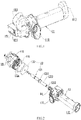
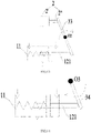
FIG. 1 is a matching diagram of a three-way valve body and a valve core assembly according to an embodiment of this disclosure. -
FIG.2 is an exploded view of the structure shown inFIG.1 . -
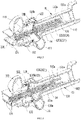
FIG.3 is a sectional view of the structure shown inFIG.1 , wherein the valve core assembly is in a first working position. -
FIG.4 is a schematic diagram of the valve core assembly in the structure shown inFIG. 3 , wherein the valve core assembly is in a second working position. -
FIG.5 is a sectional view of the structure shown inFIG.1 along another sectional position, wherein the valve core assembly is in the first working position. -
FIG.6 is a schematic diagram of the valve core assembly in the structure shown inFIG. 5 , wherein the valve core assembly is at the second working position. -
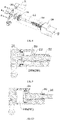
FIG.7 is a structural diagram of an electric switching mechanism according to an embodiment of this disclosure. -
FIG.8 is a sectional view of the structure shown inFIG.7 . -
FIG.9 is a sectional view of the structure shown inFIG.7 . -
FIG.10 is a schematic diagram of the structure shown inFIG.9 in another state. -
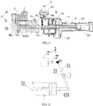
FIG.11 is a structural diagram of a three-way valve according to an embodiment of this disclosure. -
FIG.12 is a principle schematic diagram of a three-way valve according to an embodiment of this disclosure. -
FIG.13 is a schematic diagram of a three-way valve according to another embodiment of this disclosure. -
FIG.14 is a schematic diagram of a gas path of an anaesthesia machine according to an embodiment of this disclosure. - Three-
way valve body 11;Sliding cavity 110; Firstannular sealing surface 110a; Secondannular sealing surface 110b;First channel 111;Second channel 112;Third channel 113;Stopper 112a;Installation space 114; Valvecore assembly 12; Valverod 121;Flange structure 1211;Step surface 121a;First segment 1212;Second segment 1213;Sealing portion 122;First guide portion 131; First slidinggroove 131a;Second guide portion 132; Secondsliding groove 132a;Elastic element 14; Toggleassembly 15; Togglerod 151; Togglesheet 152;Position detection device 16;First travel switch 161;Second travel switch 162;Electric switching mechanism 2; power portion 2';Moving element 2";Cylinder drive element 21; Valvebase 210; Valvecavity 2101; Cavity withrod 2101a; Cavity without rod 2101b; Piston 211; Pistonrod 212; Resetspring 213;Pilot solenoid valve 22;First connection rod 31;Slide block base 32;Second connection rod 33; Three-way valve 100;Respiratory line 200; Machine-controlledbranch 300;Controller 400; Hand-controlledbranch 500;Gas storage bag 501;Pressure discharge valve 502. - It should be noted that, in the absence of conflict, the embodiments and the technical features in the embodiments of this disclosure can be combined with each other. The detailed description in the specific embodiments should be understood as an explanation of the purpose of the application and should not be regarded as an improper restriction on the application.
- In the description of the embodiments of this disclosure, "left", "right", orientation or position relationship are based on the orientation or position relationship shown in
FIG. 11 . It should be understood that these orientation terms are only for the description convenience of this disclosure and simplifying the description, rather than indicating or implying that the device or element referred to must have a specific orientation, be constructed and operated in a specific orientation. Therefore, they cannot be understood as restrictions on this disclosure. - The embodiment of this disclosure has provided a three-way valve, which includes a three-
way valve body 11, anelectric switching mechanism 2 and avalve core assembly 12. ReferringFIG.3 , the three-way valve body 11 has asliding cavity 110, afirst channel 111, asecond channel 112 and athird channel 113 which are respectively connected with thesliding cavity 110. That is, thefirst channel 111, thesecond channel 112 and thethird channel 113 are independently connected with thesliding cavity 110. - The
valve core assembly 12 is arranged inside the three-way valve body 11. Thevalve core assembly 12 includes avalve rod 121 and asealing portion 122 which is arranged at thevalve rod 121. The sealingportion 122 is arranged inside thesliding cavity 110. Thevalve rod 121 can drive the sealingportion 122 to slide inside thesliding cavity 110 in a reciprocating manner. - The
valve core assembly 12 further includes a first working position and a second working position. ReferringFIG.3 , when thevalve core assembly 12 is at the first working position, thesealing portion 122 closes thesecond channel 112 and thefirst channel 111 is connected with thethird channel 113. ReferringFIG.4 , when thevalve core assembly 12 is at the second working position, thesealing portion 122 closes thethird channel 113 and thefirst channel 111 is connected with thesecond channel 112. - The
electric switching mechanism 2 is at least partially arranged outside of the three-way valve body 11, and can drive thevalve rod 121 to move for driving thesealing portion 122 to slide inside thesliding cavity 110. It should be noted that theelectric switching mechanism 2 in the embodiment of this disclosure outputs a drive force to drive thevalve rod 121 to move after receiving an electric control signal, and thevalve rod 121 then drives thesealing portion 122 to move, so as to realize the working position switching of thevalve core assembly 12. - The application field of the three-way valve in the embodiment of this disclosure is not limited. The embodiment of this disclosure takes the application of the three-way valve in the anaesthesia machine as an example.
- Referring
FIG.15 , the anaesthesia machine includes acontroller 400, arespiratory line 200, a hand-controlledbranch 500, a machine-controlledbranch 300 and the three-way valve 100 according to an embodiment of this disclosure. Thefirst channel 111 is connected with therespiratory line 200, thesecond channel 112 is connected with the machine-controlledbranch 300, thethird channel 113 is connected with the hand-controlledbranch 500, and thecontroller 400 is electrically connected with theelectric switching mechanism 2 to control the three-way valve 100 to selectively connect the machine-controlledbranch 300 with therespiratory line 200 or connect the hand-controlledbranch 500 with therespiratory line 200. - It should be noted that the hand-controlled
branch 500 is only effective during manual respiration. Specifically, the hand-controlledbranch 500 is provided with angas storage bag 501 and apressure discharge valve 502. When thegas storage bag 501 is manually pinched too heavy, thegas storage bag 501 can discharge excess gas to prevent airway pressure injury. - When the anaesthesia machine needs to perform leak self-inspection or switch the ventilation mode for operation, or under other situation which requires checking, the anaesthesia machine can control the
electric switching mechanism 2 to input the drive force through the system program, and then control the connection state of the three-way valve 100. In the embodiment of the application, the leakage self-inspection of the anaesthesia machine is described as an example. - For leakage self-inspection under the machine-controlled mode, the machine-controlled
branch 300 is connected with therespiratory line 200. For leakage self-inspection under the hand-controlled mode, the hand-controlledbranch 500 is connected with therespiratory line 200. After the anesthesia machine has completed the leakage self-inspection under the machine-controlled mode, the anaesthesia machine automatically switches the connection state of the three-way valve 100 through the system program configuration, so that the anaesthesia machine can automatically complete the leakage self-inspection under the hand-controlled mode. It can be seen that during the leakage self-inspection of the anaesthesia machine, there is no need to manually intervene the three-way valve 100, and the full-automatic leakage self-inspection of the anaesthesia machine can be realized. -
Valve rod 121 has a certain length to facilitate sliding in the three-way valve body 11. In order to facilitate the drive connection between thevalve rod 121 and theelectric switching mechanism 2, thevalve rod 121 needs to be able to extend to an outer surface of the three-way valve body 11 or extend outside of the three-way valve body 11, or some structure of theelectric switching mechanism 2 can extend into the three-way valve body 11. It should be noted that no matter thevalve rod 121 extends into the outer surface of the three-way valve body 11 or extends outside of the three-way valve body 11, or some structure of theelectric switching mechanism 2 extends into the three-way valve body 11, it is necessary to ensure the sealing performance of the three-way valve body 11. That is, it is necessary to ensure that the three-way valve body 11 does not leak gas, so that the gas can only flow between thefirst channel 111 and thesecond channel 112, or between thefirst channel 111 and thethird channel 113. - In an embodiment, referring to
FIGs.5-6 , thesecond channel 112 approximately extends along a straight line, the slidingcavity 110 approximately extends along a straight line, wherein the slidingcavity 110 and thesecond channel 112 are located at the same straight line, thesecond channel 112 is connected to one end of the slidingcavity 110 along the length direction, thethird channel 113 is connected to the other end of the slidingcavity 110 along the length direction, and the connection position between thefirst channel 111 and the slidingcavity 110 is located at a side wall of the slidingcavity 110. - The specific structure and shape of the sealing
portion 122 are not limited as long as thesecond channel 112 or thethird channel 113 can be selectively closed. For example, in an embodiment, the sealingportion 122 is a valve sheet, and the valve sheet is in a disc shape. - In an embodiment, referring to
FIG. 4 andFIG. 6 , a junction of the slidingcavity 110 and thesecond channel 112 is provided with a firstannular sealing surface 110a, and the valve sheet abuts against the firstannular sealing surface 110a hermetically to close thesecond channel 112. Specifically, an edge portion of the valve sheet along an axial side of thevalve rod 121, abuts against the firstannular sealing surface 110a, such that the firstannular sealing surface 110a can fit the valve sheet well to ensure the gas tightness of the three-way valve and prevent the gas leakage. It should be noted that an extension dimension of the firstannular sealing surface 110a along the radial direction is relatively small, and the firstannular sealing surface 110a never contacts a surface of thevalve rod 121, so as to prevent the firstannular sealing surface 110a from blocking the gas flow. - In an embodiment, referring to
FIG. 3 andFIG. 5 , a junction of the slidingcavity 110 and thethird channel 113 has a secondannular sealing surface 110b, and the valve sheet abuts against the secondannular sealing surface 110b hermetically to close thethird channel 113. Specifically, an edge portion of the valve sheet along an axial opposite side of thevalve rod 121, abuts against the secondannular sealing surface 110b, such that the secondannular sealing surface 110b can fit the valve sheet well to ensure the gas tightness of the three-way valve and prevent the gas leakage. It should be noted that, an extension dimension of the secondannular sealing surface 110b along the radial direction is relatively small, and the secondannular sealing surface 110b never contacts the surface of thevalve rod 121, so as to prevent the secondannular sealing surface 110b from blocking the gas flow. - To facilitate the arrangement of the
valve rod 121, refer toFIG.1 . Thethird channel 113 is bent and extended, and the second end of thevalve rod 121 extends into thesecond channel 112. Referring toFIG. 5 and FIG. 6 , The first end of thevalve rod 121, which is opposite to the second channel, extends outside of the three-way valve body 11. That is, thethird channel 113 is not coaxial with thevalve rod 121 to avoid interfering the movement of thevalve rod 121. - In an embodiment, the above
electric switching mechanism 2 drives thevalve rod 121 to reciprocate, that is, theelectric switching mechanism 2 can drive thevalve core assembly 12 to switch from the first working position to the second working position, and can also drive thevalve core assembly 12 to switch from the second working position to the first working position. - In another embodiment, please refer to
FIG.5 and IFG.6. The aboveelectric switching mechanism 2 only drives thevalve rod 121 to slide in one direction. For example, theelectric switching mechanism 2 only drive thevalve rod 121 to slide from the left to the right ofFIG.5 . That is, the drivevalve core assembly 12 is switched from the second working position shown inFIG. 6 to the first working position shown inFIG. 5 , and thevalve core assembly 12 is driven to reset by other elastic structures. For example, thevalve core assembly 12 is driven by an elastic structure to be switched from the first working position shown inFIG. 5 to the second working position shown inFIG. 6 . - In order to guide the movement of the
valve rod 121, in an embodiment referring toFIG. 3 , the three-way valve includes afirst guide portion 131 which is arranged inside thesecond channel 112. Refer toFIG. 5 . Thefirst guide portion 131 has a first slidinggroove 131a which extends along a length direction of thevalve rod 121, and the second end of thevalve rod 121 penetrates into and is slidably arranged inside the first slidinggroove 131a. The first slidinggroove 131a plays a good role in guiding and positioning the movement of thevalve rod 121. - In order to facilitate an axial positioning of the
valve rod 121, in an embodiment referring toFIG.3 , the second end of thevalve rod 121 includes asecond segment 1213 and afirst segment 1212 which are adjacent to each other. An outer diameter of thefirst segment 1212 is smaller than an outer diameter of thesecond segment 1213, such that, astep surface 121a is formed at a junction of thesecond segment 1213 and thefirst segment 1212. Thefirst segment 1212 penetrates into and is slidably arranged inside the first slidinggroove 131a, and a side of thefirst guide portion 131, which faces the sealingportion 122, abuts against thestep surface 121a. Specifically, when thevalve rod 121 moves from the position shown inFIG. 6 to the right ofFIG. 6 , until thestep surface 121a abuts against thefirst guide portion 131, thefirst guide portion 131 acts as a barrier to prevent thevalve rod 121 from continuing moving. - It should be noted that when the valve core assembly is in the first working position, the
first guide portion 131 may or may not abut against thestep surface 121a. Specifically, in an embodiment in which thefirst guide portion 131 never abuts against thestep surface 121a, thefirst guide portion 131 plays a role of preventing overshooting of thevalve rod 121. - In an embodiment, please refer to
FIG.3 andFIG.5 . The three-way valve includes asecond guide portion 132 which is arranged inside the three-way valve body 11, thesecond guide portion 132 has a second slidinggroove 132a which extends along the length direction of thevalve rod 121. The second slidinggroove 132a extends outside of the three-way valve body 11, and the first end of thevalve rod 121 penetrates into and is slidably and hermetically arranged inside the second slidinggroove 132a. - It should be noted that the first end of the
valve rod 121 penetrates into and is slidably and hermetically arranged inside the second slidinggroove 132a, means that thevalve rod 121 can not only slide inside the second slidinggroove 132a, but also prevent gas flow from leaking outside of the three-way valve body 11 along the second slidinggroove 132a. Specifically, the first end of thevalve rod 121 may be sleeved with a sealing ring, and the slidable and hermetical arrangement can be realized through the sealing ring. - It can be understood that in the embodiment in which the
first guide portion 131 and thesecond guide portion 132 are provided at the same time, the first slidinggroove 131a and the second slidinggroove 132a are coaxially arranged so that the opposite ends of thevalve rod 121 can penetrate into the first slidinggroove 131a and the second slidinggroove 132a at the same time. - For example, referring to
FIG. 11 , in an embodiment of this disclosure, the electric switching structure only drives thevalve rod 121 to slide in one direction. The three-way valve also includes anelastic element 14, which drives thevalve core assembly 12 to reset. - In order to facilitate the positioning of the
elastic element 14, in an embodiment, please refer toFIG. 4 andFIG. 6 . Thesecond channel 112 has astopper 112a, and a first end of theelastic element 14 abuts against thestopper 112a, that is, thestopper 112a provides a reactive force support for theelastic element 14. A second end of theelastic element 14 can abut any appropriate position of thevalve core assembly 12 to drive thevalve core assembly 12 to move. For example, in one embodiment, the second end of theelastic element 14 abuts against the sealingportion 122, that is, theelastic element 14 directly applies a force to the sealingportion 122. For another example, in another embodiment, referring toFIG. 6 , aflange structure 1211 is formed at thevalve rod 121, and the second end of theelastic element 14 abuts against theflange structure 1211. Theflange structure 1211 increases the contact area between thevalve rod 121 and theelastic element 14, enabling a stable and reliable contact between theelastic element 14 and thevalve rod 121. - There is no limit to the type of
elastic element 14, which can be a spring, a rubber band, an elastic pad, etc. In the embodiment of this disclosure, theelastic element 14 is a spring, specifically, the spring is sleeved at thevalve rod 121, the first end of the spring abuts against thestopper 112a, and the other end of the spring abuts against theflange structure 1211. The spring has large elastic deformation which satisfies the sliding stroke requirement of the sealingportion 122 and has reliable deformation recovery ability. - In an embodiment, referring to
FIG. 11 , the three-way valve also includes aposition detection device 16 for detecting the working position of thevalve core assembly 12. When thevalve core assembly 12 is at the first working position, theposition detection device 16 can trigger and generate a first position signal; and/or when thevalve core assembly 12 is at the second working position, theposition detection device 16 can trigger and generate a second position signal. Specifically, theposition detection device 16 can be electrically connected with thecontroller 400 or other displayers to feed back the current working position of thevalve core assembly 12. The feedback of the working position of thevalve core assembly 12 through theposition detection device 16 is convenient for the user or the controller to detect whether thevalve core assembly 12 is switched in place, to determine whether thevalve core assembly 12 is stuck or not, and to improve the reliability of the three-way valve. - In an embodiment, the above
position detection device 16 triggers and generates the first position signal only when thevalve core assembly 12 is at the first working position, and never triggers and generates signal when thevalve core assembly 12 is at other positions. At this time, the default is that thevalve core assembly 12 is at the second working position. In another embodiment, the aboveposition detection device 16 triggers and generates the second position signal only when thevalve core assembly 12 is at the second working position, and never triggers and generates signal when thevalve core assembly 12 is at other positions. At this time, the default is that thevalve core assembly 12 is at the first working position. In another embodiment, the aboveposition detection device 16 triggers and generates the first position signal when thevalve core assembly 12 is at the first working position, and triggers and generates the second position signal when thevalve core assembly 12 is at the second working position. In this embodiment, whether thevalve core assembly 12 is switched in place can be determined every time through the first position signal and the second position signal, which can further increase the working reliability of the three-way valve. - The specific type of the
position detection device 16 is unlimited, as long as it can detect the corresponding position of thevalve core assembly 12. For example, theposition detection device 16 may be a Hall sensor or a photoelectric sensor, and there is no limitation here. - It should be noted that since the
valve rod 121 and the sealingportion 122 move synchronously, theposition detection device 16 can detect any portion of thevalve rod 121, any portion of the sealingportion 122, and other structures which are fixedly connected with thevalve core assembly 12. - In an embodiment, referring to
FIG.11 , theposition detection device 16 includes afirst travel switch 161 and asecond travel switch 162, the three-way valve includes atoggle assembly 15, and thevalve rod 121 is in drive connection with thetoggle assembly 15 to selectively drive thetoggle assembly 15 to trigger thefirst travel switch 161 or thesecond travel switch 162. When thevalve rod 121 moves, it drives thetoggle assembly 15 to move, thus trigging thefirst travel switch 161 or thesecond travel switch 162 by thetoggle assembly 15. For example, when thevalve rod 121 moves to the first working position, thetoggle assembly 15 contacts thefirst travel switch 161 to trigger thefirst travel switch 161. When thevalve rod 121 moves to the second working position, thetoggle assembly 15 contacts thesecond travel switch 162 to trigger thesecond travel switch 162. In this way, the position information can be fed back at both working positions of thevalve rod 121. - The specific structure of the
toggle assembly 15 is unlimited, as long as it is convenient to toggle thefirst travel switch 161 and thesecond travel switch 162. In an embodiment, please continue to refer toFIG.11 . Thetoggle assembly 15 includes atoggle rod 151 and atoggle sheet 152, wherein thetoggle sheet 152 rotates relative to the three-way valve body 11. Thetoggle sheet 152 can be rotatably arranged on the three-way valve body 11 or on other structures as long as it can rotate. - The
toggle rod 151 is fixedly connected with the first end of thevalve rod 121. Thetoggle rod 151 can drive thetoggle sheet 152 to rotate forward or backward during the linear reciprocation movement following thevalve rod 121, so as to selectively trigger thefirst travel switch 161 or thesecond travel switch 162. For example, when thevalve rod 121 moves to a certain position toward the left ofFIG. 11 , thevalve rod 121 contacts thetoggle sheet 152 and drives thetoggle sheet 152 to rotate forward along the clockwise direction inFIG.11 , thetoggle sheet 152 contacts thesecond travel switch 162 and triggers thesecond travel switch 162. When thevalve rod 121 moves to a certain position toward the right ofFIG.11 , thevalve rod 121 contacts with thetoggle sheet 152 and drives thetoggle sheet 152 to rotate backward along the counterclockwise direction inFIG.11 , thetoggle sheet 152 contacts with thefirst travel switch 161 and triggers thefirst travel switch 161. - It should be noted that the forward rotation and backward rotation are relative to each other, and never mean that a specific direction is the forward rotation or the backward rotation. For example, the clockwise rotation of the
toggle sheet 152 inFIG. 11 can be defined as the forward rotation, and the counterclockwise rotation of thetoggle sheet 152 inFIG. 11 can be defined as the backward rotation. Alternatively, the clockwise rotation of thetoggle sheet 152 inFIG. 11 can be defined as the backward rotation, and the counterclockwise rotation of thetoggle sheet 152 inFIG. 11 can be defined as the forward rotation. - In an embodiment, please refer to
FIG.3 andFIG. 11 in combination. Aninstallation space 114 is formed outside of the three-way valve body 11, and thetoggle rod 151 is arranged inside theinstallation space 114. Specifically, thetoggle rod 151 is approximately perpendicular to thevalve rod 121, the first end of thetoggle rod 151 is fixedly connected with thevalve rod 121, and the second end of thetoggle rod 151 is configured to toggle thetoggle sheet 152. Theinstallation space 114 plays a guiding role for the movement of thetoggle rod 151. Thetoggle sheet 152 is rotatably connected with other structures, that is, thetoggle sheet 152 is not connected with the three-way valve body 11, and at least part of the structure of thetoggle sheet 152 and theposition detection device 16 are located outside theinstallation space 114. In this way, thetoggle sheet 152 and theposition detection device 16 can avoid occupying theinstallation space 114, thus the three-way valve body 11 can be made compact. - In an embodiment, the electric switching structure includes a power portion 2' and a moving
element 2" which are in drive connection. The power portion 2' provides power for the movingelement 2", specifically, the power portion 2' drives the movingelement 2" to slide in a reciprocating manner or rotate, and theelectric switching mechanism 2 drives thevalve rod 121 to move through the movingelement 2". - In an embodiment, the moving
element 2" drives thevalve rod 121 to reciprocate, that is, specifically, the movingelement 2" can drive thevalve core assembly 12 to switch from the first working position to the second working position, and can also drive thevalve core assembly 12 to switch from the second working position to the first working position. - The specific form of the moving
element 2" is unlimited. When the movingelement 2" is in a rod shape, the movingelement 2" and thevalve rod 121 can be arranged along the same straight line or can be staggered. There is no restriction for this here. - The moving
element 2" can be directly connected with thevalve rod 121, or indirectly connected with thevalve rod 121 through other structures, so that thevalve rod 121 and the movingelement 2" move synchronously. - In another embodiment, referring to
FIG. 11 , the movingelement 2" and thevalve rod 121 can be selectively separated or in drive connection to push thevalve rod 121 to slide in one direction, for example, to push thevalve core assembly 12 to switch from the second working position to the first working position. In this embodiment, in order to ensure the reset of thevalve core assembly 12, the three-way valve includes the aboveelastic element 14, which is in drive connection with thevalve core assembly 12 to drive thevalve core assembly 12 to reset, such as to drive thevalve core assembly 12 to switch from the first working position to the second working position. That is, in this embodiment, the movingelement 2" and theelastic element 14 exert forces in the opposite directions at thevalve core assembly 12 to jointly drive thevalve core assembly 12 to switch between the first working position and the second working position. In this embodiment, the power portion 2' can drive the movingelement 2" to reciprocate or can drive the movingelement 2" to rotate. - In this embodiment, the moving
element 2" can directly and separably abuts against the end of thevalve rod 121, that is, the movingelement 2" directly pushes thevalve rod 121 to slide in one direction. When the movingelement 2" is in a rod shape, the movingelement 2" and thevalve rod 121 can be arranged along the same straight line or can be staggered. There is no restriction for this here. - The moving
element 2" can also indirectly push thevalve rod 121 to slide in one direction through other structures. - Specifically, in an embodiment, please refer to
FIG. 12 , the power portion 2' drives the movingelement 2" to reciprocate. Specifically, the three-way valve includes afirst connection rod 31 and aslide block base 32. Thefirst connection rod 31 penetrates into and is slidably arranged inside theslide block base 32. An end of the movingelement 2" is hinged with a first end of thefirst connection rod 31, the hinged point is point O1 inFIG.12 , one end of thevalve rod 121 slidably contacts with a second end of thefirst connection rod 31. The movingelement 2" and thevalve rod 121 are located at the same side of thefirst connection rod 31, and theslide block base 32 is hinged with other installation structure. That is, the movingelement 2, thefirst connection rod 31 and theslide block base 32 form a crank sliding mechanism. When the movingelement 2" extends along a direction towards thefirst connection rod 31, the movingelement 2" drives thefirst connection rod 31 to swing in a clockwise direction in theFIG.12 with theslide block base 32 as the center. At the same time, thefirst connection rod 31 also generates a certain linear displacement inside theslide block base 32, so that the movingelement 2" can always maintain a linear movement and avoid the clamping stagnation of the movingelement 2". - In another embodiment, referring to
FIG.13 , the power portion 2' drives the movingelement 2" to reciprocate. Specifically, the three-way valve includes asecond connection rod 33, and an end of the movingelement 2" slidably contacts with a first end of thesecond connection rod 33, thevalve rod 121 slidably contacts with a second end of thesecond connection rod 33, the movingelement 2" and thevalve rod 121 are located at the same side of thesecond connection rod 33, and a roughly middle position of thesecond connection rod 33 is rotatably connected with other installation structure, so that thesecond connection rod 33 has a rotation center O2. The movingelement 2" extends towards thesecond connection rod 33, drives thesecond connection rod 33 to rotate around the rotation center O2 along a direction of a dotted arrow inFIG. 13 . The second end of thesecond connection rod 33 forces thevalve rod 121 to retract towards the inside of the three-way valve body, that is, thevalve core assembly 12 is switched from the first working position to the second working position. When thevalve core assembly 12 needs to be switched from the second working position to the first working position, the movingelement 2" moves away from thesecond connection rod 33 to eliminate the drive of the movingelement 2" at thevalve rod 121, and thevalve rod 121 is reset under the action of the above elastic element, that is, thevalve core assembly 12 is switched from the second working position to the first working position. - In a further embodiment, referring to
FIG.14 , the power portion 2' drives the movingelement 2" to rotate. Specifically, the three-way valve includes athird connection rod 34, and the movingelement 2" is rotatably connected with thethird connection rod 34. The rotation connection point is O3, and the movingelement 2" drives thethird connection rod 34 to rotate around the rotation connection point O3. It should be noted that the movingelement 2" and the power portion 2' are not shown inFIG.14 . In the state shown inFIG.14 , thethird connection rod 34 rotates along a direction of a dotted arrow with the rotation connection point O3 as a center to drive the three-way valve to switch. In this embodiment, the power portion may be a rotation motor. - The specific structural form of the above power portion 2' is unlimited, as long as it can provide power for the moving
part 2" . - For example, in an embodiment, referring to
FIGs.7 and8 , the power portion 2' includes acylinder drive element 21 and apilot solenoid valve 22, and the movingelement 2" is apiston rod 212. Specifically, thecylinder drive element 21 includes avalve base 210 and apiston 211 which is fixedly connected with thepiston rod 212. Referring toFIGs. 9 and 10 , thevalve base 210 has avalve cavity 2101 and a first gas inlet connected with thevalve cavity 2101. Thepiston 211 separates thevalve cavity 2101 into a cavity withrod 2101a and a cavity without rod 2101b. The first gas inlet is connected with the cavity without rod 2101b, and thepilot solenoid valve 22 can connect the first gas inlet with the gas source, so that thepiston rod 212 drives thevalve rod 121 to move. It should be noted that the specific type and structure of thepilot solenoid valve 22 are not limited. For example, in an embodiment, the valve core opening of thepilot solenoid valve 22 can be adjusted. For example, during specific implementation, valve core opening of thepilot solenoid valve 22 can be adjusted by controlling current or voltage applied to a control terminal of thepilot solenoid valve 22, so as to control the gas flows which pass through thesolenoid pilot valve 22, thus controlling a switching speed of the three-way valve. In another embodiment, gas intaking speed or gas discharging speed of the gas path can be controlled by arranging a throttle valve or orifice on the gas path to increase the gas resistance, so that the switching speed of the three-way valve can be controlled. It is understandable that the size of the throttle valve can be fixed or adjustable, and the orifice diameter can be fixed or adjustable. - Similarly, in this embodiment, the
piston rod 212 can drive thevalve rod 121 to reciprocate or slide in one direction. - When the
piston rod 212 needs to extend out from thevalve cavity 2101, thepilot solenoid valve 22 is powered on, and the gas from the gas source enters the cavity without rod 2101b from the first gas inlet through thepilot solenoid valve 22. The gas pushes thepiston 211 to move towards the cavity withoutrod 2101a, thereby extending out thepiston rod 212 to drive thevalve rod 121 to move. - When the
piston rod 212 needs to reset, the cavity withrod 2101a can be connected with the gas source to drive thepiston 211 to move towards the cavity without rod 2101b, thus driving thepiston rod 212 to reset. Therefore, in this embodiment, thevalve base 210 also has a second gas inlet which is connected with the cavity without rod 2101b, and thepilot solenoid valve 22 can selectively connect the gas source with the first gas inlet or the second gas inlet. Specifically, when thepiston rod 212 needs to extend out, the gas, which enters from the first gas inlet and then is discharged from the second gas inlet, pushes thepiston 211 to move towards the cavity withrod 2101a, so that thepiston rod 212 extends out. When thepiston rod 212 needs to retract, the gas, which enters from the second gas inlet and then is discharged from the first gas inlet, pushes thepiston 211 to move towards the cavity without rod 2101b, so that thepiston rod 212 retracts. - In another embodiment, please continue to refer to
FIGS. 9 and 10 . The cavity withrod 2101a is connected with atmosphere, that is, the cavity withrod 2101a is not closed, and thecylinder drive element 21 includes areturn spring 213, which is sleeved at thepiston rod 212 and can drive thepiston rod 212 to reset. In this embodiment, thepiston rod 212 is driven to reset by thereturn spring 213, and there is no need to seal the cavity withrod 2101a or control the gas intake and gas discharge of the cavity withrod 2101a through thepilot solenoid valve 22, which can reduce the manufacture difficulty of thecylinder drive element 21 and simplify the gas path control. It should be noted that in this embodiment, during the reset process of thepiston rod 212, the gas in the cavity without rod 2101b needs to be discharged and the gas in the cavity without rod 2101b can be discharged through thepilot solenoid valve 22 mentioned above, or through other valves, which are not limited here. - In another embodiment, the
electric switching mechanism 2 is a linear motor, which includes a stator and a mover. The mover can reciprocate relative to the stator. Specifically, the power portion 2' is the stator of the linear motor, and the movingelement 2" is the mover of the linear motor. - It should be noted that in the embodiment shown in
FIG. 12 , the movingelement 2" can be the above piston rod or the above mover. Similarly, in the embodiment shown inFIG. 13 , the movingelement 2" can be the above piston rod or the above mover. - The embodiments/implementations provided in this disclosure can be combined with each other without contradiction.
- The above descriptions are only preferred embodiments of this disclosure and are not intended to limit this disclosure. For those skilled in the art, this disclosure may have various changes and modifications. Any modification, equivalent replacement, improvement, etc., made within the spirit and principles of this disclosure shall be included in the protection scope of this disclosure.
Claims (18)
- A three-way valve, characterized in that, comprising:a three-way valve body, wherein the three-way valve body is provided with a sliding cavity, and a first channel, a second channel and a third channel which are respectively connected with the sliding cavity;a valve core assembly which is arranged inside the three-way valve body, wherein the valve core assembly comprises a valve rod and a sealing portion which is arranged at the valve rod, the valve rod can drive the sealing portion to slide inside the sliding cavity in a reciprocating manner; wherein the valve core assembly further comprises a first working position and a second working position, when the valve core assembly is at the first working position, the sealing portion closes the second channel and the first channel is connected with the third channel, when the valve core assembly is at the second working position, the sealing portion closes the third channel and the first channel is connected with the second channel; andan electric switching mechanism which is at least partially arranged outside of the three-way valve body, wherein the electric switching mechanism can drive the valve rod to move for driving the sealing portion to slide inside the sliding cavity.
- The three-way valve according to claim 1, characterized in that, the three-way valve further comprises an elastic element which drives the valve core assembly to reset.
- The three-way valve according to claim 2, characterized in that, a second end of the valve rod extends into the second channel, wherein the second channel is provided with a stopper and a first end of the elastic element abuts against the stopper;
a second end of the elastic element abuts against the sealing portion, or a flange structure is formed at the valve rod and a second end of the elastic element abuts against the flange structure. - The three-way valve according to claim 1, characterized in that, the three-way valve further comprises a first guide portion which is arranged inside the second channel; wherein the first guide portion is provided with a first sliding groove which extends along a length direction of the valve rod, and a second end of the valve rod penetrates into and is slidably arranged inside the first sliding groove.
- The three-way valve according to claim 4, characterized in that, the second end of the valve rod comprises a first segment and a second segment which are adjacent to each other; wherein an outer diameter of the first segment is smaller than an outer diameter of the second segment, such that a step surface is formed at a junction of the second segment and the first segment; wherein the first segment penetrates into and is slidably arranged inside the first sliding groove, and a side of the first guide portion, which faces the sealing portion, abuts against the step surface.
- The three-way valve according to claim 1, characterized in that, the three-way valve further comprises a second guide portion which is arranged inside the three-way valve body; wherein the second guide portion is provided with a second sliding groove which extends outside of the three-way valve body along a length direction of the valve rod, wherein a first end of the valve rod penetrates into and is slidably and hermetically arranged inside the second sliding groover.
- The three-way valve according to claim 1, characterized in that, the three-way valve further comprises a position detection device which is configured to detect a working position of the valve core assembly; wherein when the valve core assembly is at the first working position, the position detection device can trigger and generate a first position signal; and/or when the valve core assembly is at the second working position, the position detection device can trigger and generate a second position signal.
- The three-way valve according to claim 7, characterized in that, the position detection device comprise a first travel switch and a second travel switch, the three-way valve comprises a toggle assembly, wherein the valve rod is in drive connection with the toggle assembly to selectively drive the toggle assembly to trigger the first travel switch or the second travel switch.
- The three-way valve according to claim 8, characterized in that, the toggle assembly comprises a toggle rod and a toggle sheet, the toggle sheet rotates relative to the three-way valve body, the toggle rod is fixedly connected with a first end of the valve rod; wherein the toggle rod can drive the toggle sheet to rotate forward or backward during a linear reciprocation movement following the valve rod, so as to selectively trigger the first travel switch or the second travel switch.
- The three-way valve according to claim 9, characterized in that, an installation space is formed outside of the three-way valve body, and the toggle rod is arranged inside the installation space.
- The three-way valve according to claim 1, characterized in that, the sealing portion is a valve sheet, wherein a junction of the sliding cavity and the second channel is provided with a first annular sealing surface, and the valve sheet can hermetically abut against the first annular sealing surface to close the second channel; and/or a junction of the sliding cavity and the third channel is provided with a second annular sealing surface, and the valve sheet can hermetically abut against the second annular sealing surface hermetically to close the third channel.
- The three-way valve according to claim 1, characterized in that, the electric switching structure comprises a power portion and a moving element which are in drive connection, wherein the power portion drives the moving element to slide in a reciprocating manner or rotate, and the electric switching mechanism drives the valve rod to slide through the moving element.
- The three-way valve according to claim 12, characterized in that, the moving element drives the valve rod to slide in a reciprocating manner.
- The three-way valve according to claim 12, characterized in that, the moving element and the valve rod can be selectively separated or in drive connection to push the valve rod to slide in one direction, wherein the three-way valve further comprises an elastic element which is in drive connection with the valve core assembly to drive the valve core assembly to reset.
- The three-way valve according to any one of claims 12-14, characterized in that, the power portion comprises a cylinder drive element and a pilot solenoid valve, wherein the moving element is a piston rod, the cylinder drive element comprises a valve base and a piston which is fixedly connected with the piston rod, the valve base is provided with a valve cavity and a first gas inlet which is connected with the valve cavity, wherein the piston separates the valve cavity into a cavity with rod and a cavity without rod, the first gas inlet is connected with the cavity without rod, and the pilot solenoid valve can connect the first gas inlet with a gas source, so that the piston rod can drive the valve rod to move.
- The three-way valve according to claim 15, characterized in that, the cavity with rod is connected with atmosphere, the cylinder drive element further comprises a return spring, which is sleeved at the piston rod and can drive the piston rod to reset.
- The three-way valve according to any one of claims 12-14, characterized in that, the electric switching mechanism is a linear motor, the power portion is a stator of the linear motor, and the moving element is a mover of the linear motor.
- An anaesthesia machine, characterized in that, comprising a controller, a respiratory line, a hand-controlled branch, a machine-controlled branch and the three-way valve according to any one of claims 1-17, wherein the first channel is connected with the respiratory line, the second channel is connected with the machine-controlled branch, the third channel is connected with the hand-controlled branch, and the controller is electrically connected with the electric switching mechanism to control the three-way valve to selectively connect the machine-controlled branch with the respiratory line or connect the hand-controlled branch with the respiratory line.
Applications Claiming Priority (1)
| Application Number | Priority Date | Filing Date | Title |
|---|---|---|---|
| PCT/CN2019/130182 WO2021134349A1 (en) | 2019-12-30 | 2019-12-30 | Three-way valve and anaesthesia machine |
Publications (2)
| Publication Number | Publication Date |
|---|---|
| EP4086489A1 true EP4086489A1 (en) | 2022-11-09 |
| EP4086489A4 EP4086489A4 (en) | 2022-12-21 |
Family
ID=76687520
Family Applications (1)
| Application Number | Title | Priority Date | Filing Date |
|---|---|---|---|
| EP19958322.0A Pending EP4086489A4 (en) | 2019-12-30 | 2019-12-30 | THREE-WAY VALVE AND ANESTHESIA MACHINE |
Country Status (3)
| Country | Link |
|---|---|
| EP (1) | EP4086489A4 (en) |
| CN (1) | CN114829816A (en) |
| WO (1) | WO2021134349A1 (en) |
Families Citing this family (9)
| Publication number | Priority date | Publication date | Assignee | Title |
|---|---|---|---|---|
| CN114001179B (en) * | 2021-10-22 | 2023-10-20 | 福建西河卫浴科技有限公司 | Water diverter valve and shower unit |
| CN114159662B (en) * | 2021-11-01 | 2024-02-02 | 北京谊安医疗系统股份有限公司 | Output switching device for fresh gas of anesthesia machine |
| CN114209943B (en) * | 2021-11-23 | 2024-10-01 | 北京谊安医疗系统股份有限公司 | Switching device for driving gas of anesthesia machine |
| CN114294281B (en) * | 2021-12-26 | 2024-11-12 | 浙江海宏液压科技股份有限公司 | Working valve plate and electro-hydraulic proportional multi-way valve |
| CN115040743B (en) * | 2022-07-04 | 2025-11-11 | 威高(苏州)医疗科技有限公司 | Anesthesia machine and gas circuit switching system thereof |
| CN116236657B (en) * | 2022-12-23 | 2025-08-01 | 北京谊安医疗系统股份有限公司 | Electric control evaporator and control method thereof |
| CN117553139A (en) * | 2023-10-31 | 2024-02-13 | 湖南明康中锦医疗科技股份有限公司 | A three-layer coaxial airway two-position five-way valve |
| CN118636586B (en) * | 2024-06-04 | 2025-10-10 | 厦门汉印股份有限公司 | Ink feeding mechanism, ink feeding mechanism control method and printer |
| CN119792749B (en) * | 2024-12-30 | 2025-11-18 | 深圳麦科田生物医疗技术股份有限公司 | Self-test method for anesthesia machine, self-test interface display method and anesthesia machine |
Family Cites Families (13)
| Publication number | Priority date | Publication date | Assignee | Title |
|---|---|---|---|---|
| US4442998A (en) * | 1979-07-24 | 1984-04-17 | Aisin Seiki Kabushiki Kaisha | Electromagnetic valve unit |
| US5474107A (en) * | 1993-09-03 | 1995-12-12 | The Horton Company | Fail-open solenoid actuated valve |
| JP2003083458A (en) * | 2001-07-02 | 2003-03-19 | Tgk Co Ltd | Four-way selector valve |
| US7159615B2 (en) * | 2003-02-12 | 2007-01-09 | Isuzu Motors Limited | Flow control valve |
| US7328719B2 (en) * | 2004-08-10 | 2008-02-12 | Ross Operating Valve Company | Valve state sensing module |
| CN203463715U (en) * | 2013-07-29 | 2014-03-05 | 上海申吉仪表有限公司 | Pneumatic and manual transformable three-way control valve |
| CN103821965A (en) * | 2014-01-25 | 2014-05-28 | 哈电集团哈尔滨电站阀门有限公司 | High-pressure heater three-way valve driven by inner high-pressure piston |
| CN105517614B (en) * | 2014-12-02 | 2017-10-03 | 深圳迈瑞生物医疗电子股份有限公司 | Anesthesia breathing system and its disinfection control method |
| CN104482246A (en) * | 2014-12-30 | 2015-04-01 | 特瑞斯能源装备股份有限公司 | Three-way valve |
| CN105090559B (en) * | 2015-08-31 | 2017-06-13 | 宁波索诺工业自控设备有限公司 | Cut-off type two-position-five-way solenoid valve |
| CN207064709U (en) * | 2017-06-14 | 2018-03-02 | 南通市力沛流体阀业有限公司 | Electronic high plus triple valve |
| CN110220010A (en) * | 2019-06-28 | 2019-09-10 | 珠海格力电器股份有限公司 | Valve and water purification equipment |
| CN110307360A (en) * | 2019-07-31 | 2019-10-08 | 三一汽车制造有限公司 | Oil-way switching apparatus, oil path control system and vehicle |
-
2019
- 2019-12-30 WO PCT/CN2019/130182 patent/WO2021134349A1/en not_active Ceased
- 2019-12-30 EP EP19958322.0A patent/EP4086489A4/en active Pending
- 2019-12-30 CN CN201980103069.8A patent/CN114829816A/en active Pending
Also Published As
| Publication number | Publication date |
|---|---|
| CN114829816A (en) | 2022-07-29 |
| EP4086489A4 (en) | 2022-12-21 |
| WO2021134349A1 (en) | 2021-07-08 |
Similar Documents
| Publication | Publication Date | Title |
|---|---|---|
| WO2021134349A1 (en) | Three-way valve and anaesthesia machine | |
| US4605396A (en) | Gravity flow cassette with rotary valve | |
| US12320341B2 (en) | Micro piston pump | |
| US4037994A (en) | Pressure unloading valve device for compressor | |
| CN108506516B (en) | A kind of long-life ball valve | |
| US20100135831A1 (en) | Miniature Pump Device with an Anti-Free Flow Valve | |
| US20240068465A1 (en) | Peristaltic pump | |
| CN112107770A (en) | Air circuit switching device for anesthesia breathing loop | |
| CN111110971B (en) | Control switch, anesthesia machine ventilation system and anesthesia machine | |
| US20080251372A1 (en) | Combination pressure switch | |
| CN212960119U (en) | Pneumatic stop valve | |
| CN104595149B (en) | swash plate type variable displacement compressor | |
| CN101629566B (en) | Combination pressure switch | |
| CN221033412U (en) | Anti-jamming self-reciprocating pneumatic motor with operation monitoring function | |
| EP4245339B1 (en) | Fluid passage/stop apparatus and ventilation treatment device | |
| CN215780595U (en) | Sectional administration type injector | |
| CN104373628A (en) | Four-way valve | |
| JP6927030B2 (en) | Driving machine | |
| JP6426114B2 (en) | Gas circuit breaker | |
| CN119362163B (en) | An overvoltage protection system | |
| US20170062157A1 (en) | Gas Circuit Breaker | |
| CN119664743A (en) | An anti-stuck self-reciprocating pneumatic motor with operation monitoring function | |
| CN221541519U (en) | Shunting tire pressure gun | |
| CN114215805B (en) | Reversing valve | |
| CN209781742U (en) | Vacuum valve and evacuating device |
Legal Events
| Date | Code | Title | Description |
|---|---|---|---|
| STAA | Information on the status of an ep patent application or granted ep patent |
Free format text: STATUS: THE INTERNATIONAL PUBLICATION HAS BEEN MADE |
|
| PUAI | Public reference made under article 153(3) epc to a published international application that has entered the european phase |
Free format text: ORIGINAL CODE: 0009012 |
|
| STAA | Information on the status of an ep patent application or granted ep patent |
Free format text: STATUS: REQUEST FOR EXAMINATION WAS MADE |
|
| 17P | Request for examination filed |
Effective date: 20220729 |
|
| AK | Designated contracting states |
Kind code of ref document: A1 Designated state(s): AL AT BE BG CH CY CZ DE DK EE ES FI FR GB GR HR HU IE IS IT LI LT LU LV MC MK MT NL NO PL PT RO RS SE SI SK SM TR |
|
| A4 | Supplementary search report drawn up and despatched |
Effective date: 20221123 |
|
| RIC1 | Information provided on ipc code assigned before grant |
Ipc: F16K 31/42 20060101ALI20221117BHEP Ipc: A61M 16/01 20060101ALI20221117BHEP Ipc: F16K 11/044 20060101AFI20221117BHEP |
|
| DAV | Request for validation of the european patent (deleted) | ||
| DAX | Request for extension of the european patent (deleted) | ||
| STAA | Information on the status of an ep patent application or granted ep patent |
Free format text: STATUS: EXAMINATION IS IN PROGRESS |
|
| 17Q | First examination report despatched |
Effective date: 20231109 |
|
| GRAP | Despatch of communication of intention to grant a patent |
Free format text: ORIGINAL CODE: EPIDOSNIGR1 |
|
| STAA | Information on the status of an ep patent application or granted ep patent |
Free format text: STATUS: GRANT OF PATENT IS INTENDED |
|
| INTG | Intention to grant announced |
Effective date: 20251113 |
|
| GRAJ | Information related to disapproval of communication of intention to grant by the applicant or resumption of examination proceedings by the epo deleted |
Free format text: ORIGINAL CODE: EPIDOSDIGR1 |
|
| STAA | Information on the status of an ep patent application or granted ep patent |
Free format text: STATUS: EXAMINATION IS IN PROGRESS |
|
| GRAP | Despatch of communication of intention to grant a patent |
Free format text: ORIGINAL CODE: EPIDOSNIGR1 |
|
| STAA | Information on the status of an ep patent application or granted ep patent |
Free format text: STATUS: GRANT OF PATENT IS INTENDED |
|
| INTC | Intention to grant announced (deleted) | ||
| INTG | Intention to grant announced |
Effective date: 20260327 |