EP4086485A1 - Mechanical unlocking mechanism for electronic parking - Google Patents
Mechanical unlocking mechanism for electronic parking Download PDFInfo
- Publication number
- EP4086485A1 EP4086485A1 EP20925825.0A EP20925825A EP4086485A1 EP 4086485 A1 EP4086485 A1 EP 4086485A1 EP 20925825 A EP20925825 A EP 20925825A EP 4086485 A1 EP4086485 A1 EP 4086485A1
- Authority
- EP
- European Patent Office
- Prior art keywords
- parking
- pawl
- assembly
- pull
- pull cord
- Prior art date
- Legal status (The legal status is an assumption and is not a legal conclusion. Google has not performed a legal analysis and makes no representation as to the accuracy of the status listed.)
- Granted
Links
Images


Classifications
-
- F—MECHANICAL ENGINEERING; LIGHTING; HEATING; WEAPONS; BLASTING
- F16—ENGINEERING ELEMENTS AND UNITS; GENERAL MEASURES FOR PRODUCING AND MAINTAINING EFFECTIVE FUNCTIONING OF MACHINES OR INSTALLATIONS; THERMAL INSULATION IN GENERAL
- F16H—GEARING
- F16H63/00—Control outputs from the control unit to change-speed- or reversing-gearings for conveying rotary motion or to other devices than the final output mechanism
- F16H63/02—Final output mechanisms therefor; Actuating means for the final output mechanisms
- F16H63/30—Constructional features of the final output mechanisms
- F16H63/34—Locking or disabling mechanisms
- F16H63/3416—Parking lock mechanisms or brakes in the transmission
- F16H63/3425—Parking lock mechanisms or brakes in the transmission characterised by pawls or wheels
-
- F—MECHANICAL ENGINEERING; LIGHTING; HEATING; WEAPONS; BLASTING
- F16—ENGINEERING ELEMENTS AND UNITS; GENERAL MEASURES FOR PRODUCING AND MAINTAINING EFFECTIVE FUNCTIONING OF MACHINES OR INSTALLATIONS; THERMAL INSULATION IN GENERAL
- F16H—GEARING
- F16H63/00—Control outputs from the control unit to change-speed- or reversing-gearings for conveying rotary motion or to other devices than the final output mechanism
- F16H63/02—Final output mechanisms therefor; Actuating means for the final output mechanisms
- F16H63/30—Constructional features of the final output mechanisms
- F16H63/34—Locking or disabling mechanisms
- F16H63/3416—Parking lock mechanisms or brakes in the transmission
- F16H63/3491—Emergency release or engagement of parking locks or brakes
-
- F—MECHANICAL ENGINEERING; LIGHTING; HEATING; WEAPONS; BLASTING
- F16—ENGINEERING ELEMENTS AND UNITS; GENERAL MEASURES FOR PRODUCING AND MAINTAINING EFFECTIVE FUNCTIONING OF MACHINES OR INSTALLATIONS; THERMAL INSULATION IN GENERAL
- F16H—GEARING
- F16H61/00—Control functions within control units of change-speed- or reversing-gearings for conveying rotary motion ; Control of exclusively fluid gearing, friction gearing, gearings with endless flexible members or other particular types of gearing
- F16H61/26—Generation or transmission of movements for final actuating mechanisms
- F16H61/36—Generation or transmission of movements for final actuating mechanisms with at least one movement being transmitted by a cable
-
- F—MECHANICAL ENGINEERING; LIGHTING; HEATING; WEAPONS; BLASTING
- F16—ENGINEERING ELEMENTS AND UNITS; GENERAL MEASURES FOR PRODUCING AND MAINTAINING EFFECTIVE FUNCTIONING OF MACHINES OR INSTALLATIONS; THERMAL INSULATION IN GENERAL
- F16H—GEARING
- F16H63/00—Control outputs from the control unit to change-speed- or reversing-gearings for conveying rotary motion or to other devices than the final output mechanism
- F16H63/02—Final output mechanisms therefor; Actuating means for the final output mechanisms
- F16H63/30—Constructional features of the final output mechanisms
- F16H63/34—Locking or disabling mechanisms
- F16H63/3416—Parking lock mechanisms or brakes in the transmission
- F16H63/3425—Parking lock mechanisms or brakes in the transmission characterised by pawls or wheels
- F16H63/3433—Details of latch mechanisms, e.g. for keeping pawls out of engagement
Definitions
- the present disclosure relates to the field of parking control, and more particularly, to a mechanical unlocking mechanism for electronic parking.
- the electronic parking mechanism of gearbox is a mechanism for preventing the vehicle from sliding forward or sliding backward when the vehicle is parked on a road or a ramp.
- most electronic parking mechanisms of gearbox in new energy vehicles have insufficient structural flexibility and short service life.
- the mechanical unlocking mechanism is provided at the worm of the parking motor; when the parking motor is powered off, this unlocking method requires the driver to operate under the vehicle to perform mechanical unlocking, and thus has low safety and poor comfort.
- the present disclosure provides a mechanical unlocking mechanism for electronic parking to solve or partially solve the above problems.
- the present disclosure provides a mechanical unlocking mechanism for electronic parking, comprising: a parking cam assembly, a pawl assembly, a parking gear, a pull cord assembly and an actuating assembly;
- the pull cord assembly comprises a pull wire and a guide shaft screw, each of two ends of the pull wire is provided with a pull wire ball head rod, the pull wire ball head rod is connected with an end of the pull wire and is connected with an end hole of the parking guide shaft or the actuating assembly via the guide shaft screw sleeved on the pull wire.
- a ball head of the pull wire ball head rod is engaged with the end hole with a clearance fit, and a certain axial space is reserved.
- the pull cord assembly further comprises a pull wire roller that is installed on a cylindrical stand inside the gearbox casing to change a guide direction of the pull wire.
- the actuating assembly is a pull rod or a rocker arm structure, and the pull rod or rocker arm structure is connected with a vehicle pull wire or a vehicle pull rod outside the gearbox; and the pull rod is installed on a positioning hole leading to outside of the gearbox casing.
- the rocker arm structure comprises a rocker arm, a stop washer, a pull cord guide wheel and a rocker arm shaft cover;
- rocker arm structure further comprises a sealing ring arranged between the pull cord guide wheel and the rocker arm shaft cover.
- the mechanical unlocking mechanism further comprises an elastic assembly
- the elastic assembly comprises a thrust bearing, a return spring and a thrust bearing washer sleeved at the distal end of the parking guide shaft in turn; a ball end of the thrust bearing abuts against a parking cam position-limiting plate, one end of the return spring abuts against a plane end of the thrust bearing, the other end is fixedly connected with the thrust bearing washer, the thrust bearing washer abuts against the gearbox casing, and the return spring is provided with a preload.
- the pawl shaft is fixed on two sides of the gearbox casing
- the torsion spring failure prevention assembly comprises a guide pin and a guide slot, the guide pin is arranged at an end of a guide part at the distal end of the pawl, the guide slot is arranged on the parking cam and/or the parking cam position-limiting plate, and the guide pin extends into the guide slot.
- the above mechanical unlocking mechanism for electronic parking has the following advantages.
- the mechanical unlocking mechanism according to the present disclosure can provide an emergent mechanical unlocking function when the parking motor is powered off.
- the parking guide shaft is connected with the actuating assembly arranged on the gearbox via the pull cord assembly, so that the driver can mechanically unlock in the cab.
- the mechanical unlocking mechanism can realize the pure mechanical unlocking in the cab without power supply, the driver does not need to get off the vehicle for operation, so it has high safety performance and good operation comfort.
- the mechanical unlocking mechanism according to the present disclosure by providing the torsion spring failure prevention assembly, can still realize parking unlocking in case of torsion spring failure, and can effectively prevent the pawl from falling into the parking gear groove in the non-parking state.
- the mechanical unlocking mechanism comprises a parking cam assembly, a pawl assembly, a parking gear 17, a pull cord assembly 5 and an actuating assembly.
- the parking cam assembly comprises a parking guide shaft 11, a parking cam position-limiting plate 9, an axial position-limiting block 10 and a parking cam 13.
- the parking cam position-limiting plate 9 is fixed on the parking guide shaft 11, the axial position-limiting block 10 is sleeved on the parking guide shaft 11 with an interference fit, the parking cam 13 is sleeved on the parking guide shaft 11 between the axial position-limiting block 10 and the parking cam position-limiting plate 9, and the parking cam position-limiting plate 9 can drive the parking cam 13 to rotate.
- the axial position-limiting block 10 limits the position of the parking cam 13 in the axial direction, and the parking cam 13 can rotate flexibly around the parking guide shaft 11 between the axial position-limiting block 10 and the parking cam position-limiting plate 9.
- the outer side of the parking cam 13 is provided with an arc protrusion along the circumferential direction.
- the parking cam position-limiting plate 9 fixed on it rotates accordingly, and the parking cam position-limiting plate 9 further drives the parking cam 13 to rotate.
- a heel part of the parking cam 13 is provided with a circumferential contour extending in the axial direction of the parking guide shaft 11, and the arc protrusion is arranged on the outer side of the circumferential contour.
- the parking guide shaft 11 has a flat shaft end on one end thereof and a circular shaft end on the other end thereof.
- the flat shaft end of the parking guide shaft 11 runs through the gearbox casing.
- the circular shaft end of the parking guide shaft 11 is fixed in the gearbox casing.
- the flat shaft end of the parking guide shaft 11 is connected with the parking motor.
- the parking motor drives the parking guide shaft to rotate, and the parking guide shaft 11 can move axially.
- the parking cam position-limiting plate 9 comprises at least a first blade part and a second blade part provided with an interval therebetween, the first blade part and the second blade part are respectively provided on two sides of the heel part; a side of the first blade part facing the heel part is provided with a first spring column, the heel part is provided with a corresponding second spring column, and a paddle spring 12 is sleeved on the first spring column and the second spring column; the second blade part is formed with a curved claw, and the curved claw abuts against the other side of the heel part.
- the pawl assembly comprises a pawl 16 and a pawl shaft 1.
- One side of the distal end of the pawl 16 abuts against the side of the parking cam 13 that is provided with the arc protrusion.
- the other side of the distal end of the pawl 16 is provided with a boss that can be inserted into the parking gear 17.
- the pawl shaft 1 is arranged at the other end of the pawl 16.
- the pawl 16 can swing around the pawl shaft 1.
- the pawl 16 With the rotation and translation of the parking cam 13, the pawl 16 is respectively in a first position where the parking gear 17 parks in and is fixed and a second position where the parking gear 17 parks out and is rotatable.
- the parking gear 17 is in a fixed state or a rotatable state respectively, so as to realize parking or driving.
- the pull cord assembly 5 is connected with the actuating assembly, and the other end is connected with the parking guide shaft 11.
- the pull cord assembly 5 can drive the parking guide shaft 11 to translate in the axial direction.
- the pull cord assembly 5 is arranged in the gearbox casing.
- the actuating assembly drives, via the pull cord assembly 5, the parking guide shaft 11 to translate, thereby driving the pawl 16 to move from the first position to the second position.
- the arc protrusion on the parking cam 13 contacts with the pawl assembly.
- the position relationship between the parking cam 13 and the pawl 16 in the parking-in state is shown in FIG. 5 .
- the pawl 16 is in the first position where the parking gear 17 parks in and is fixed.
- the actuating assembly can be operated manually and mechanically, so that the actuating assembly further makes the parking guide shaft 11 move axially via the pull cord assembly 5.
- the arc protrusion no longer presses the pawl assembly, and the pawl 16 moves from the first position where the parking gear 17 parks in and is fixed to the second position where the parking gear 17 parks out and is rotatable, thereby realizing unlocking the parking of the vehicle.
- the position relationship between the parking cam 13 and the pawl 16 after mechanically unlocked is shown in FIG. 6 .
- the mechanical unlocking mechanism according to this embodiment does not need to perform mechanical unlocking under the vehicle, and it has the advantages of simple operation, high safety and good comfort.
- the pull cord assembly 5 comprises a pull wire 5-3 and a guide shaft screw 5-2.
- Each of two ends of the pull wire 5-3 is provided with a pull wire ball head rod 5-1.
- the pull wire ball head rod 5-1 is connected with the end of the pull wire 5-3 by riveting, and is connected with an end hole of the parking guide shaft 11 or the actuating assembly via the guide shaft screw 5-2 sleeved on the pull wire 5-3.
- the connection between the pull wire 5-3 and the parking guide shaft 11 or the actuating structure may also be realized in other ways, and is not limited to the above way.
- a ball head of the pull wire ball head rod 5-1 is engaged with the end hole with a clearance fit, and a certain axial space is reserved.
- the ball head of the pull wire ball head rod 5-1 is engaged with the end hole of the parking guide shaft 11 with a clearance fit, and a certain axial space is reserved, so that the pull wire 5-3 is in a loose state before performing mechanical unlocking to prevent the pull wire 5-3 from being in a tight state for a long time and deformed, thereby increasing the service life of the pull wire 5-3.
- the pull cord assembly 5 further comprises a pull wire roller 4 that is installed on a cylindrical stand inside the gearbox casing to change a guide direction of the pull wire 5-3.
- the guide direction of the pull wire 5-3 can be arbitrarily changed by providing the pull wire roller 4 to facilitate setting the position of the actuating assembly.
- the actuating assembly is a pull rod 3 or a rocker arm structure 18, and the pull rod 3 or the rocker arm structure 18 is connected with a pull wire 5-3 outside the gearbox casing.
- the actuating assembly is connected to the control part in the cab via the vehicle pull wire or vehicle pull rod, and the driver can perform the mechanical unlocking action in the cab.
- the pull rod 3 is installed in a positioning hole leading to the outside of the gearbox casing.
- the pull rod 3 passes through the gearbox casing, one end is in the gearbox casing and is connected with the pull cord assembly 5, and the other end is outside the gearbox casing and is connected with the vehicle pull wire or the vehicle pull rod.
- the rocker arm structure 18 comprises a rocker arm 18-5, a stop washer 18-4, a pull cord guide wheel 18-1, and a rocker arm shaft cover 18-3.
- One end of the pull cord guide wheel 18-1 is engaged with a hole on the gearbox casing with a clearance fit to fix the rocker arm structure 18.
- the lower part of the pull cord guide wheel 18-1 is provided with a radial heel part that is connected with the pull cord assembly 5, more specifically, connected with the pull wire 5-3.
- the rocker arm 18-5 is fixed on the other end of the pull cord guide wheel 18-1 via the stop washer 18-4.
- the stop washer 18-4 is used to position the rocker arm 18-5.
- the rocker arm shaft cover 18-3 is sleeved on the pull cord guide wheel 18-1 between the radial heel part and the rocker arm 18-5 and is fixed on the gearbox casing.
- the rocker arm 18-5 can be connected to the control part in the cab via the vehicle pull wire, and the driver can perform unlocking by operating the control part in the cab.
- the rocker arm structure 18 further comprises a sealing ring 18-2 arranged between the pull cord guide wheel 18-1 and the rocker arm shaft cover 18-3, and the sealing ring 18-2 seals the rocker arm shaft cover 18-3.
- the mechanical unlocking mechanism further comprises an elastic assembly.
- the elastic assembly comprises a thrust bearing 8, a return spring 7 and a thrust bearing washer 6 sleeved at an end of the parking guide shaft 11 in turn.
- the ball end of the thrust bearing 8 abuts against the parking cam position-limiting plate 9, one end of the return spring 7 abuts against the plane end of the thrust bearing 8, and the other end is fixedly connected with the thrust bearing washer 6.
- the thrust bearing washer 6 abuts against the gearbox casing.
- the return spring 7 is provided with a preload, and an oil seal is provided at the place where the circular shaft end of the parking guide shaft 11 contacts the gearbox casing to play a role of isolation.
- the elastic assembly abuts against the gearbox casing.
- the parking cam assembly moves axially to the circular shaft end of the parking guide shaft 11, and the elastic assembly is further compressed toward the gearbox casing.
- the pawl shaft 1 is fixed on two sides of the gearbox casing, and the pawl 16 can rotate around the pawl shaft 1.
- the pawl assembly further comprises a torsion spring 2, one end of the torsion spring 2 is fixed on the gearbox casing, and the other end of the torsion spring 2 is fixed on the pawl 16, so that the pawl 16 is preloaded on the parking cam 13. Under the action of the torsion spring 2, the pawl 16 always abuts against the parking cam 13.
- the upper part of the pawl 16 is provided with a groove
- the roller 14 is fixed in the groove via a roller pin 15
- the roller 14 contacts the parking cam 13
- the lower part of the pawl 16 is provided with a boss to engage with the parking gear 17.
- the pawl 16 When the parking mechanism is in the parking-in state, the pawl 16 is pressed down by the parking cam 13, so that the boss at the lower part of the pawl 16 is engaged with the parking gear 17 to realize parking.
- One side of the pawl 16 is sleeved on the pawl shaft 1, the pawl shaft 1 is fixed on two sides of the gearbox casing, and the pawl 16 can rotate around the pawl shaft 1.
- One end of the torsion spring 2 is fixed on the gearbox casing, and the other end is fixed on the pawl 16.
- the torsion spring 2 is provided with a certain preload force during installation. The preload force always lifts the pawl 16 upward, so that the pawl 16 is preloaded on the parking cam 13.
- the roller 14 can roll around the roller pin 15 to reduce the friction between the parking cam 13 and the pawl 16, and the roller 14 contacts the circumferential contour or arc protrusion on the parking cam 13.
- the unlocking mechanism further comprises a tor
- the torsion spring failure prevention assembly comprises a guide pin 19 and a guide slot
- the guide pin 19 is arranged at an end of a guide part at the distal end of the pawl 16
- the guide slot is arranged on the parking cam 13 and/or the parking cam position-limiting plate 9
- the guide pin 19 extends into the guide slot
- the guide slot provides a guiding function to lift up the pawl 16 in case of emergency unlocking.
- the pawl 16 can be movably connected with the parking cam 13. Even if the torsion spring 2 fails, due to the rotation of the parking cam 13, the guide pin 19 drives the pawl 16 to lift up so that the boss at the lower part of the pawl 16 is separated from the parking gear 17, thereby realizing the parking unlocking. In the non-parking state, the guide pin 19 remains at the bottom of the guide slot of the parking cam 13 to prevent the boss of the pawl 16 from falling into the tooth groove of the parking gear 17.
- the torsion spring failure prevention assembly overcomes the problem that the parking cannot be unlocked normally due to the failure of torsion spring 2.
- the present disclosure provides a mechanical unlocking mechanism for electronic parking, which comprises a parking cam assembly, a pawl assembly, a parking gear, a pull cord assembly and an actuating assembly;
- the parking cam assembly comprises a parking guide shaft, a parking cam position-limiting plate, an axial position-limiting block and a parking cam, the parking cam position-limiting plate is fixed on the parking guide shaft, the axial position-limiting block is sleeved on the parking guide shaft with an interference fit, the parking cam is sleeved on the parking guide shaft between the axial position-limiting block and the parking cam position-limiting plate, and an outer side of the parking cam is provided with an arc protrusion along a circumferential direction;
- the pawl assembly comprises a pawl and a pawl shaft, one side of a distal end of the pawl abuts against a side of the parking cam that is provided with the arc protrusion, the other side of the distal end of the pawl is provided with a boss that
- the mechanical unlocking mechanism provides an emergent mechanical unlocking function when the parking motor is powered off.
- the parking guide shaft is connected with the actuating assembly arranged on the gearbox via the pull cord assembly, so that the driver can mechanically unlock in the cab.
- the mechanical unlocking mechanism can realize the pure mechanical unlocking in the cab without power supply, the driver does not need to get off the vehicle for operation, so it has high safety performance and good operation comfort.
Landscapes
- Engineering & Computer Science (AREA)
- General Engineering & Computer Science (AREA)
- Mechanical Engineering (AREA)
- Gear-Shifting Mechanisms (AREA)
- Braking Arrangements (AREA)
Abstract
Description
- The present disclosure relates to the field of parking control, and more particularly, to a mechanical unlocking mechanism for electronic parking.
- The electronic parking mechanism of gearbox is a mechanism for preventing the vehicle from sliding forward or sliding backward when the vehicle is parked on a road or a ramp. At present, most electronic parking mechanisms of gearbox in new energy vehicles have insufficient structural flexibility and short service life. Moreover, the mechanical unlocking mechanism is provided at the worm of the parking motor; when the parking motor is powered off, this unlocking method requires the driver to operate under the vehicle to perform mechanical unlocking, and thus has low safety and poor comfort.
- In view of the above problems, the present disclosure provides a mechanical unlocking mechanism for electronic parking to solve or partially solve the above problems.
- In order to achieve the above object, the present disclosure adopts the following technical solutions.
- The present disclosure provides a mechanical unlocking mechanism for electronic parking, comprising: a parking cam assembly, a pawl assembly, a parking gear, a pull cord assembly and an actuating assembly;
- the parking cam assembly comprises a parking guide shaft and a parking cam, the parking cam is sleeved on the parking guide shaft, and an outer side of the parking cam is provided with an arc protrusion along a circumferential direction;
- the pawl assembly comprises a pawl and a pawl shaft, one side of a distal end of the pawl abuts against a side of the parking cam that is provided with the arc protrusion, the other side of the distal end of the pawl is provided with a boss that can insert into the parking gear, the pawl shaft is arranged at the other end of the pawl, the pawl can swing around the pawl shaft, and with rotation and translation of the parking cam, the pawls are respectively in a first position where the parking gear parks in and is fixed and a second position where the parking gear parks out and is rotatable;
- one end of the pull cord assembly is connected with the actuating assembly, and the other end of the pull cord assembly is connected with the parking guide shaft, and the pull cord assembly can drive the parking guide shaft to translate in the axial direction; and
- the actuating assembly drives, via the pull cord assembly, the parking guide shaft to translate, thereby driving the pawl to move from the first position to the second position.
- Further, the pull cord assembly comprises a pull wire and a guide shaft screw, each of two ends of the pull wire is provided with a pull wire ball head rod, the pull wire ball head rod is connected with an end of the pull wire and is connected with an end hole of the parking guide shaft or the actuating assembly via the guide shaft screw sleeved on the pull wire.
- Further, a ball head of the pull wire ball head rod is engaged with the end hole with a clearance fit, and a certain axial space is reserved.
- Further, the pull cord assembly further comprises a pull wire roller that is installed on a cylindrical stand inside the gearbox casing to change a guide direction of the pull wire.
- Further, the actuating assembly is a pull rod or a rocker arm structure, and the pull rod or rocker arm structure is connected with a vehicle pull wire or a vehicle pull rod outside the gearbox; and
the pull rod is installed on a positioning hole leading to outside of the gearbox casing. - Further, the rocker arm structure comprises a rocker arm, a stop washer, a pull cord guide wheel and a rocker arm shaft cover;
- one end of the pull cord guide wheel is engaged with a hole on the gearbox casing with a clearance fit to fix the rocker arm structure;
- a lower part of the pull cord guide wheel is provided with a radial protrusion which is connected with the pull cord assembly; and
- the rocker arm is fixed on the other end of the pull cord guide wheel via the stop washer, and the rocker arm shaft cover is sleeved on the pull cord guide wheel between the radial protrusion and the rocker arm, and is fixed on the gearbox casing.
- Further, the rocker arm structure further comprises a sealing ring arranged between the pull cord guide wheel and the rocker arm shaft cover.
- Further, the mechanical unlocking mechanism further comprises an elastic assembly, the elastic assembly comprises a thrust bearing, a return spring and a thrust bearing washer sleeved at the distal end of the parking guide shaft in turn;
a ball end of the thrust bearing abuts against a parking cam position-limiting plate, one end of the return spring abuts against a plane end of the thrust bearing, the other end is fixedly connected with the thrust bearing washer, the thrust bearing washer abuts against the gearbox casing, and the return spring is provided with a preload. - Further, the pawl shaft is fixed on two sides of the gearbox casing;
- the pawl can rotate around the pawl shaft;
- the pawl assembly further comprises a torsion spring, one end of the torsion spring is fixed on the gearbox casing, and the other end of the torsion spring is fixed on the pawl, so that the pawl and the parking cam are preloaded; and
- the unlocking mechanism further comprises a torsion spring failure prevention assembly.
- Further, the torsion spring failure prevention assembly comprises a guide pin and a guide slot, the guide pin is arranged at an end of a guide part at the distal end of the pawl, the guide slot is arranged on the parking cam and/or the parking cam position-limiting plate, and the guide pin extends into the guide slot.
- The above mechanical unlocking mechanism for electronic parking has the following advantages.
- The mechanical unlocking mechanism according to the present disclosure can provide an emergent mechanical unlocking function when the parking motor is powered off. The parking guide shaft is connected with the actuating assembly arranged on the gearbox via the pull cord assembly, so that the driver can mechanically unlock in the cab. As the mechanical unlocking mechanism can realize the pure mechanical unlocking in the cab without power supply, the driver does not need to get off the vehicle for operation, so it has high safety performance and good operation comfort. The mechanical unlocking mechanism according to the present disclosure, by providing the torsion spring failure prevention assembly, can still realize parking unlocking in case of torsion spring failure, and can effectively prevent the pawl from falling into the parking gear groove in the non-parking state.
- The above is only an overview of the technical solutions of the present disclosure. In order to better understand the technical means of the present disclosure so that it can be implemented according to the contents of the description, and in order to make the above and other objects, features and advantages of the present disclosure more obvious and easy to understand, the specific embodiments of the present disclosure are given below.
-
-
FIG. 1 is a schematic view of the structure of a mechanical unlocking mechanism for electronic parking according to an embodiment of the present disclosure; -
FIG. 2 is a schematic view of the structure of a pull cord assembly according to an embodiment of the present disclosure; -
FIG. 3 is a schematic view of the structure of a mechanical unlocking mechanism for electronic parking according to an embodiment of the present disclosure; -
FIG. 4 is a schematic view of the structure of a rocker arm assembly according to an embodiment of the present disclosure; -
FIG. 5 is a schematic view of the structure of a parking cam and a pawl in the parking-in state according to an embodiment of the present disclosure; -
FIG. 6 is a schematic view of the structure of the parking cam and pawl after mechanically unlocked according to an embodiment of the present disclosure; and -
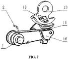
FIG. 7 is a schematic view of the structure of a torsion spring failure prevention assembly according to an embodiment of the present disclosure. - In the drawings: 1. pawl shaft, 2. torsion spring, 3. pull rod, 4. pull wire roller, 5. pull cord assembly, 6. thrust bearing washer, 7. return spring, 8. thrust bearing, 9. parking cam position-limiting plate, 10. axial position-limiting block, 11. parking guide shaft, 12. paddle spring, 13. parking cam, 14. roller, 15. roller pin, 16. pawl, 17. parking gear, 18. rocker arm structure, 19. guide pin, 5-1. pull wire ball head rod, 5-2. guide shaft screw, 5-3. pull wire, 18-1. cord guide wheel, 18-2. sealing ring, 18-3. rocker shaft cover, 18-4. stop washer, 18-5. rocker arm.
- Illustrative embodiments of the present disclosure will be described in more detail with reference to the drawings. Although the drawings show the illustrative embodiments of the present disclosure, it should be understood that the present disclosure can be implemented in various ways and should not be limited by the embodiments disclosed herein. On the contrary, the embodiments are provided for a more thorough and complete understanding of the present disclosure, so as to fully convey the scope of the present disclosure to those skilled in the art.
- As shown in
FIG. 1 , the present disclosure provides a mechanical unlocking mechanism for electronic parking. The mechanical unlocking mechanism comprises a parking cam assembly, a pawl assembly, aparking gear 17, apull cord assembly 5 and an actuating assembly. - Specifically, the parking cam assembly comprises a
parking guide shaft 11, a parking cam position-limiting plate 9, an axial position-limitingblock 10 and aparking cam 13. The parking cam position-limiting plate 9 is fixed on theparking guide shaft 11, the axial position-limitingblock 10 is sleeved on theparking guide shaft 11 with an interference fit, theparking cam 13 is sleeved on theparking guide shaft 11 between the axial position-limitingblock 10 and the parking cam position-limiting plate 9, and the parking cam position-limiting plate 9 can drive theparking cam 13 to rotate. The axial position-limitingblock 10 limits the position of theparking cam 13 in the axial direction, and theparking cam 13 can rotate flexibly around theparking guide shaft 11 between the axial position-limitingblock 10 and the parking cam position-limiting plate 9. - The outer side of the
parking cam 13 is provided with an arc protrusion along the circumferential direction. When theparking guide shaft 11 rotates, the parking cam position-limiting plate 9 fixed on it rotates accordingly, and the parking cam position-limiting plate 9 further drives theparking cam 13 to rotate. A heel part of theparking cam 13 is provided with a circumferential contour extending in the axial direction of theparking guide shaft 11, and the arc protrusion is arranged on the outer side of the circumferential contour. When the circumferential contour contacts with the pawl assembly, the pawl assembly is in a lift-up state, and thepawl 16 is in a second position where theparking gear 17 parks out and is rotatable. When the arc protrusion on the circumferential contour contacts with the pawl assembly, the pawl assembly is in a press-down state, thepawl 16 is in a first position where theparking gear 17 parks in and is fixed. The circumferential contour limits the position of the parking pawl assembly and makes the parking pawl assembly movable within a certain range. In this embodiment, theparking guide shaft 11 has a flat shaft end on one end thereof and a circular shaft end on the other end thereof. The flat shaft end of theparking guide shaft 11 runs through the gearbox casing. The circular shaft end of theparking guide shaft 11 is fixed in the gearbox casing. The flat shaft end of theparking guide shaft 11 is connected with the parking motor. The parking motor drives the parking guide shaft to rotate, and theparking guide shaft 11 can move axially. - As shown in
FIG. 1 , the parking cam position-limiting plate 9 comprises at least a first blade part and a second blade part provided with an interval therebetween, the first blade part and the second blade part are respectively provided on two sides of the heel part; a side of the first blade part facing the heel part is provided with a first spring column, the heel part is provided with a corresponding second spring column, and apaddle spring 12 is sleeved on the first spring column and the second spring column; the second blade part is formed with a curved claw, and the curved claw abuts against the other side of the heel part. - The pawl assembly comprises a
pawl 16 and a pawl shaft 1. One side of the distal end of thepawl 16 abuts against the side of theparking cam 13 that is provided with the arc protrusion. The other side of the distal end of thepawl 16 is provided with a boss that can be inserted into theparking gear 17. The pawl shaft 1 is arranged at the other end of thepawl 16. Thepawl 16 can swing around the pawl shaft 1. With the rotation and translation of theparking cam 13, thepawl 16 is respectively in a first position where theparking gear 17 parks in and is fixed and a second position where theparking gear 17 parks out and is rotatable. With the rotation of theparking cam 13 and the rotation of thepawl 16 around the pawl shaft 1, theparking gear 17 is in a fixed state or a rotatable state respectively, so as to realize parking or driving. - One end of the
pull cord assembly 5 is connected with the actuating assembly, and the other end is connected with theparking guide shaft 11. Thepull cord assembly 5 can drive theparking guide shaft 11 to translate in the axial direction. Thepull cord assembly 5 is arranged in the gearbox casing. - The actuating assembly drives, via the
pull cord assembly 5, theparking guide shaft 11 to translate, thereby driving thepawl 16 to move from the first position to the second position. - In sum, in the embodiment of the present disclosure, when the vehicle is in the parking-in state, the arc protrusion on the
parking cam 13 contacts with the pawl assembly. The position relationship between theparking cam 13 and thepawl 16 in the parking-in state is shown inFIG. 5 . Thepawl 16 is in the first position where theparking gear 17 parks in and is fixed. When the parking motor cannot rotate to unlock the electric parking, the actuating assembly can be operated manually and mechanically, so that the actuating assembly further makes theparking guide shaft 11 move axially via thepull cord assembly 5. The arc protrusion no longer presses the pawl assembly, and thepawl 16 moves from the first position where theparking gear 17 parks in and is fixed to the second position where theparking gear 17 parks out and is rotatable, thereby realizing unlocking the parking of the vehicle. The position relationship between theparking cam 13 and thepawl 16 after mechanically unlocked is shown inFIG. 6 . The mechanical unlocking mechanism according to this embodiment does not need to perform mechanical unlocking under the vehicle, and it has the advantages of simple operation, high safety and good comfort. - In an embodiment, as shown in
FIG. 2 , thepull cord assembly 5 comprises a pull wire 5-3 and a guide shaft screw 5-2. Each of two ends of the pull wire 5-3 is provided with a pull wire ball head rod 5-1. The pull wire ball head rod 5-1 is connected with the end of the pull wire 5-3 by riveting, and is connected with an end hole of theparking guide shaft 11 or the actuating assembly via the guide shaft screw 5-2 sleeved on the pull wire 5-3. Of course, the connection between the pull wire 5-3 and theparking guide shaft 11 or the actuating structure may also be realized in other ways, and is not limited to the above way. - In an embodiment, a ball head of the pull wire ball head rod 5-1 is engaged with the end hole with a clearance fit, and a certain axial space is reserved. The ball head of the pull wire ball head rod 5-1 is engaged with the end hole of the
parking guide shaft 11 with a clearance fit, and a certain axial space is reserved, so that the pull wire 5-3 is in a loose state before performing mechanical unlocking to prevent the pull wire 5-3 from being in a tight state for a long time and deformed, thereby increasing the service life of the pull wire 5-3. - In an embodiment, the
pull cord assembly 5 further comprises a pull wire roller 4 that is installed on a cylindrical stand inside the gearbox casing to change a guide direction of the pull wire 5-3. The guide direction of the pull wire 5-3 can be arbitrarily changed by providing the pull wire roller 4 to facilitate setting the position of the actuating assembly. There may be one or more pull wire rollers 4. - In an embodiment, as shown in
FIG. 1 orFIG. 3 , the actuating assembly is apull rod 3 or arocker arm structure 18, and thepull rod 3 or therocker arm structure 18 is connected with a pull wire 5-3 outside the gearbox casing. In addition, the actuating assembly is connected to the control part in the cab via the vehicle pull wire or vehicle pull rod, and the driver can perform the mechanical unlocking action in the cab. - The
pull rod 3 is installed in a positioning hole leading to the outside of the gearbox casing. Thepull rod 3 passes through the gearbox casing, one end is in the gearbox casing and is connected with thepull cord assembly 5, and the other end is outside the gearbox casing and is connected with the vehicle pull wire or the vehicle pull rod. - In an embodiment, as shown in
FIG. 4 , therocker arm structure 18 comprises a rocker arm 18-5, a stop washer 18-4, a pull cord guide wheel 18-1, and a rocker arm shaft cover 18-3. One end of the pull cord guide wheel 18-1 is engaged with a hole on the gearbox casing with a clearance fit to fix therocker arm structure 18. The lower part of the pull cord guide wheel 18-1 is provided with a radial heel part that is connected with thepull cord assembly 5, more specifically, connected with the pull wire 5-3. The rocker arm 18-5 is fixed on the other end of the pull cord guide wheel 18-1 via the stop washer 18-4. The stop washer 18-4 is used to position the rocker arm 18-5. The rocker arm shaft cover 18-3 is sleeved on the pull cord guide wheel 18-1 between the radial heel part and the rocker arm 18-5 and is fixed on the gearbox casing. The rocker arm 18-5 can be connected to the control part in the cab via the vehicle pull wire, and the driver can perform unlocking by operating the control part in the cab. - In an embodiment, the
rocker arm structure 18 further comprises a sealing ring 18-2 arranged between the pull cord guide wheel 18-1 and the rocker arm shaft cover 18-3, and the sealing ring 18-2 seals the rocker arm shaft cover 18-3. - In an embodiment, as shown in
FIG. 1 , the mechanical unlocking mechanism further comprises an elastic assembly. The elastic assembly comprises a thrust bearing 8, a return spring 7 and athrust bearing washer 6 sleeved at an end of theparking guide shaft 11 in turn. The ball end of the thrust bearing 8 abuts against the parking cam position-limiting plate 9, one end of the return spring 7 abuts against the plane end of the thrust bearing 8, and the other end is fixedly connected with thethrust bearing washer 6. Thethrust bearing washer 6 abuts against the gearbox casing. The return spring 7 is provided with a preload, and an oil seal is provided at the place where the circular shaft end of theparking guide shaft 11 contacts the gearbox casing to play a role of isolation. Due to the preload force of the return spring 7, the elastic assembly abuts against the gearbox casing. When the parking mechanism is mechanically unlocked, the parking cam assembly moves axially to the circular shaft end of theparking guide shaft 11, and the elastic assembly is further compressed toward the gearbox casing. - In an embodiment, the pawl shaft 1 is fixed on two sides of the gearbox casing, and the
pawl 16 can rotate around the pawl shaft 1. The pawl assembly further comprises atorsion spring 2, one end of thetorsion spring 2 is fixed on the gearbox casing, and the other end of thetorsion spring 2 is fixed on thepawl 16, so that thepawl 16 is preloaded on theparking cam 13. Under the action of thetorsion spring 2, thepawl 16 always abuts against theparking cam 13. In order to improve the reliable contact between thepawl 16 and theparking cam 13, reduce the friction and wear of the contact part between the upper part of thepawl 16 and theparking cam 13, and improve its service life, the upper part of thepawl 16 is provided with a groove, theroller 14 is fixed in the groove via aroller pin 15, theroller 14 contacts theparking cam 13, and the lower part of thepawl 16 is provided with a boss to engage with theparking gear 17. - When the parking mechanism is in the parking-in state, the
pawl 16 is pressed down by theparking cam 13, so that the boss at the lower part of thepawl 16 is engaged with theparking gear 17 to realize parking. One side of thepawl 16 is sleeved on the pawl shaft 1, the pawl shaft 1 is fixed on two sides of the gearbox casing, and thepawl 16 can rotate around the pawl shaft 1. One end of thetorsion spring 2 is fixed on the gearbox casing, and the other end is fixed on thepawl 16. Thetorsion spring 2 is provided with a certain preload force during installation. The preload force always lifts thepawl 16 upward, so that thepawl 16 is preloaded on theparking cam 13. Theroller 14 can roll around theroller pin 15 to reduce the friction between theparking cam 13 and thepawl 16, and theroller 14 contacts the circumferential contour or arc protrusion on theparking cam 13. The unlocking mechanism further comprises a torsion spring failure prevention assembly. - In an embodiment, as shown in
FIG. 7 , the torsion spring failure prevention assembly comprises aguide pin 19 and a guide slot, theguide pin 19 is arranged at an end of a guide part at the distal end of thepawl 16, the guide slot is arranged on theparking cam 13 and/or the parking cam position-limiting plate 9, theguide pin 19 extends into the guide slot, and the guide slot provides a guiding function to lift up thepawl 16 in case of emergency unlocking. When thetorsion spring 2 fails, the pawl assembly loses the preload force from thetorsion spring 2, and thus when the parking unlocking is performed, the boss provided at the lower part of thepawl 16 cannot be disengaged from theparking gear 17, and the parking unlocking cannot be realized. - In this embodiment of the present disclosure, by providing the
guide pin 19 and the guide slot, thepawl 16 can be movably connected with theparking cam 13. Even if thetorsion spring 2 fails, due to the rotation of theparking cam 13, theguide pin 19 drives thepawl 16 to lift up so that the boss at the lower part of thepawl 16 is separated from theparking gear 17, thereby realizing the parking unlocking. In the non-parking state, theguide pin 19 remains at the bottom of the guide slot of theparking cam 13 to prevent the boss of thepawl 16 from falling into the tooth groove of theparking gear 17. In this embodiment, the torsion spring failure prevention assembly overcomes the problem that the parking cannot be unlocked normally due to the failure oftorsion spring 2. - In sum, the present disclosure provides a mechanical unlocking mechanism for electronic parking, which comprises a parking cam assembly, a pawl assembly, a parking gear, a pull cord assembly and an actuating assembly; the parking cam assembly comprises a parking guide shaft, a parking cam position-limiting plate, an axial position-limiting block and a parking cam, the parking cam position-limiting plate is fixed on the parking guide shaft, the axial position-limiting block is sleeved on the parking guide shaft with an interference fit, the parking cam is sleeved on the parking guide shaft between the axial position-limiting block and the parking cam position-limiting plate, and an outer side of the parking cam is provided with an arc protrusion along a circumferential direction; the pawl assembly comprises a pawl and a pawl shaft, one side of a distal end of the pawl abuts against a side of the parking cam that is provided with the arc protrusion, the other side of the distal end of the pawl is provided with a boss that can be inserted into the parking gear, the pawl shaft is arranged at the other end of the pawl, the pawl can swing around the pawl shaft, and with rotation and translation of the parking cam, the pawl is respectively in a first position where the parking gear parks in and is fixed and a second position where the parking gear parks out and is rotatable; one end of the pull cord assembly is connected with the actuating assembly, and the other end of the pull cord assembly is connected with the parking guide shaft, and the pull cord assembly can drive the parking guide shaft to translate in the axial direction; the actuating assembly drives, via the pull cord assembly, the parking guide shaft to translate, thereby driving the pawl to move from the first position to the second position. The mechanical unlocking mechanism according to the present disclosure provides an emergent mechanical unlocking function when the parking motor is powered off. The parking guide shaft is connected with the actuating assembly arranged on the gearbox via the pull cord assembly, so that the driver can mechanically unlock in the cab. As the mechanical unlocking mechanism can realize the pure mechanical unlocking in the cab without power supply, the driver does not need to get off the vehicle for operation, so it has high safety performance and good operation comfort.
- The above merely describes particular embodiments of the present disclosure. By the teaching of the present disclosure, a person skilled in the art can make other modifications or variations based on the above embodiments. A person skilled in the art should appreciate that, the detailed description above is only for the purpose of better explaining the present disclosure, and the protection scope of the present disclosure should be subject to the protection scope of the claims.
Claims (10)
- A mechanical unlocking mechanism for electronic parking, characterized by comprising: a parking cam assembly, a pawl assembly, a parking gear (17), a pull cord assembly (5) and an actuating assembly;the parking cam assembly comprises a parking guide shaft (11) and a parking cam (13), the parking cam (13) is sleeved on the parking guide shaft (11), and an outer side of the parking cam (13) is provided with an arc protrusion along a circumferential direction;the pawl assembly comprises a pawl (16) and a pawl shaft (1), one side of a distal end of the pawl (16) abuts against a side of the parking cam (13) that is provided with the arc protrusion, the other side of the distal end of the pawl (16) is provided with a boss that can be inserted into the parking gear (17), the pawl shaft (1) is arranged at the other end of the pawl (16), the pawl (16) can swing around the pawl shaft (1), and with rotation and translation of the parking cam (13), the pawls (16) are respectively in a first position where the parking gear (17) parks in and is fixed and a second position where the parking gear (17) parks out and is rotatable;one end of the pull cord assembly (5) is connected with the actuating assembly, and the other end of the pull cord assembly (5) is connected with the parking guide shaft (11), and the pull cord assembly (5) can drive the parking guide shaft (11) to translate in an axial direction; andthe actuating assembly drives, via the pull cord assembly (5), the parking guide shaft (11) to translate, thereby driving the pawl (16) to move from the first position to the second position.
- The mechanical unlocking mechanism according to claim 1, characterized in that: the pull cord assembly (5) comprises a pull wire (5-3) and a guide shaft screw (5-2), each of two ends of the pull wire (5-3) is provided with a pull wire ball head rod (5-1), the pull wire ball head rod (5-1) is connected with an end of the pull wire (5-3) and is connected with an end hole of the parking guide shaft (11) or the actuating assembly via the guide shaft screw (5-2) sleeved on the pull wire (5-3).
- The mechanical unlocking mechanism according to claim 2, characterized in that: a ball head of the pull wire ball head rod (5-1) is engaged with the end hole with a clearance fit, and a certain axial space is reserved.
- The mechanical unlocking mechanism according to claim 2, characterized in that: the pull cord assembly (5) further comprises a pull wire roller (4) that is installed on a cylindrical stand inside the gearbox casing to change a guide direction of the pull wire (5-3).
- The mechanical unlocking mechanism according to claim 1, characterized in that: the actuating assembly is a pull rod (3) or a rocker arm structure (18), and the pull rod (3) or rocker arm structure (18) is connected with a vehicle pull wire (5-3) or a vehicle pull rod (3) outside the gearbox; and
the pull rod (3) is installed on a positioning hole leading to outside of the gearbox casing. - The mechanical unlocking mechanism according to claim 5, characterized in that: the rocker arm structure (18) comprises a rocker arm (18-5), a stop washer (18-4), a pull cord guide wheel (18-1) and a rocker arm shaft cover (18-3);one end of the pull cord guide wheel (18-1) is engaged with a hole on the gearbox casing with a clearance fit to fix the rocker arm structure (18);a lower part of the pull cord guide wheel (18-1) is provided with a radial protrusion which is connected with the pull cord assembly (5); andthe rocker arm (18-5) is fixed on the other end of the pull cord guide wheel (18-1) via the stop washer (18-4), and the rocker arm shaft cover (18-3) is sleeved on the pull cord guide wheel (18-1) between the radial protrusion and the rocker arm (18-5), and is fixed on the gearbox casing.
- The mechanical unlocking mechanism according to claim 6, characterized in that: the rocker arm structure (18) further comprises a sealing ring (18-2) arranged between the pull cord guide wheel (18-1) and the rocker arm shaft cover (18-3).
- The mechanical unlocking mechanism according to claim 1, further characterized by comprising: an elastic assembly, whereinthe elastic assembly comprises a thrust bearing (8), a return spring (7) and a thrust bearing washer (6) sleeved at an end of the parking guide shaft (11) in turn; anda ball end of the thrust bearing (8) abuts against the parking cam position-limiting plate (9), one end of the return spring (7) abuts against a plane end of the thrust bearing (8), the other end is fixedly connected with the thrust bearing washer (6), the thrust bearing washer (6) abuts against the gearbox casing, and the return spring (7) is provided with a preload.
- The mechanical unlocking mechanism according to any one of claims 1-8, characterized in that: the pawl shaft (1) is fixed on two sides of the gearbox casing;the pawl (16) can rotate around the pawl shaft (1);the pawl assembly further comprises a torsion spring (2), one end of the torsion spring (2) is fixed on the gearbox casing, and the other end of the torsion spring (2) is fixed on the pawl (16), so that the pawl (16) is preloaded on the parking cam (13); andthe unlocking mechanism further comprises a torsion spring failure prevention assembly.
- The mechanical unlocking mechanism according to claim 9, characterized in that: the torsion spring failure prevention assembly comprises a guide pin (19) and a guide slot, the guide pin (19) is arranged at an end of a guide part at the distal end of the pawl (16), the guide slot is arranged on the parking cam (13) and/or the parking cam position-limiting plate (9), and the guide pin (19) extends into the guide slot.
Applications Claiming Priority (2)
| Application Number | Priority Date | Filing Date | Title |
|---|---|---|---|
| CN202010186448.2A CN111237453B (en) | 2020-03-17 | 2020-03-17 | Mechanical unlocking mechanism for electronic parking |
| PCT/CN2020/083763 WO2021184455A1 (en) | 2020-03-17 | 2020-04-08 | Mechanical unlocking mechanism for electronic parking |
Publications (3)
| Publication Number | Publication Date |
|---|---|
| EP4086485A1 true EP4086485A1 (en) | 2022-11-09 |
| EP4086485A4 EP4086485A4 (en) | 2023-02-22 |
| EP4086485B1 EP4086485B1 (en) | 2024-03-06 |
Family
ID=70873557
Family Applications (1)
| Application Number | Title | Priority Date | Filing Date |
|---|---|---|---|
| EP20925825.0A Active EP4086485B1 (en) | 2020-03-17 | 2020-04-08 | Mechanical unlocking mechanism for electronic parking |
Country Status (5)
| Country | Link |
|---|---|
| US (1) | US11761535B2 (en) |
| EP (1) | EP4086485B1 (en) |
| JP (1) | JP7269452B2 (en) |
| CN (1) | CN111237453B (en) |
| WO (1) | WO2021184455A1 (en) |
Cited By (1)
| Publication number | Priority date | Publication date | Assignee | Title |
|---|---|---|---|---|
| CN119393517A (en) * | 2024-10-12 | 2025-02-07 | 西安航天精密机电研究所 | A miniaturized locking device for a transfer mechanism and a transfer mechanism |
Families Citing this family (10)
| Publication number | Priority date | Publication date | Assignee | Title |
|---|---|---|---|---|
| CN110953341B (en) * | 2019-12-26 | 2024-09-24 | 精进电动科技股份有限公司 | Electronic parking mechanism |
| CN112145682A (en) * | 2020-09-29 | 2020-12-29 | 苏州东风精冲工程有限公司 | Novel electronic parking mechanism and parking system |
| CN113246758A (en) * | 2021-04-27 | 2021-08-13 | 南京康尼新能源汽车零部件有限公司 | Transmission mechanism of charging socket electronic lock |
| CN113696862A (en) * | 2021-07-07 | 2021-11-26 | 泰安芒特机械科技有限公司 | Parking braking device for crawler-type walking machinery |
| CN114458702B (en) * | 2022-02-18 | 2023-06-02 | 中国第一汽车股份有限公司 | Speed reducer disconnecting device, speed reducer and vehicle |
| CN115046007B (en) * | 2022-06-17 | 2023-04-14 | 安徽江淮汽车集团股份有限公司 | Electronic parking mechanism of transmission |
| US20240026945A1 (en) * | 2022-07-25 | 2024-01-25 | Vanderbilt University | Human adaptable variable stiffness springs |
| CN115507178A (en) * | 2022-09-22 | 2022-12-23 | 精进电动科技股份有限公司 | Car parking device, parking system and car |
| CN116771818B (en) * | 2023-06-29 | 2025-12-05 | 浙江奥思伟尔电动科技有限公司 | A parking brake mechanism for a pure electric vehicle reducer |
| CN117345866B (en) * | 2023-11-21 | 2026-04-07 | 江苏御传新能源科技有限公司 | Manual unlocking device and method for parking mechanism, speed reducer and new energy vehicle |
Family Cites Families (21)
| Publication number | Priority date | Publication date | Assignee | Title |
|---|---|---|---|---|
| US2964135A (en) * | 1957-08-19 | 1960-12-13 | Gen Motors Corp | Brake mechanism |
| DE102008006398A1 (en) * | 2008-01-28 | 2009-07-30 | Zf Friedrichshafen Ag | Emergency unlocking device for parking brake |
| US8505705B2 (en) | 2009-12-30 | 2013-08-13 | Borgwarner, Inc. | Stamped laminated stacks for parking pawl, parking gear and parking anchor |
| CN203189708U (en) | 2013-01-17 | 2013-09-11 | 安徽江淮汽车股份有限公司 | Connection mechanism for parking mechanism |
| EP2971872B1 (en) | 2013-03-15 | 2020-12-23 | Dana Automotive Systems Group, LLC | Parking lock mechanism for a transmission |
| US9145113B2 (en) * | 2013-05-24 | 2015-09-29 | GM Global Technology Operations LLC | Transmission parking pawl actuation assembly |
| JP6110333B2 (en) * | 2014-04-21 | 2017-04-05 | 本田技研工業株式会社 | Vehicle parking lock release device |
| US9353859B2 (en) * | 2014-09-03 | 2016-05-31 | E-Aam Driveline Systems Ab | Park lock mechanism |
| DE102016210757B3 (en) * | 2016-06-16 | 2017-06-01 | Siemens Aktiengesellschaft | Parking brake and operating procedures |
| KR101855720B1 (en) | 2016-08-12 | 2018-05-09 | 현대 파워텍 주식회사 | Parking release device for automatic transmission |
| JP2018080799A (en) * | 2016-11-18 | 2018-05-24 | トヨタ自動車株式会社 | Manual release device for positioning member and parking lock mechanism |
| CN207093744U (en) | 2017-08-09 | 2018-03-13 | 中国第一汽车股份有限公司 | A kind of double disengaging type automatic transmission stopping mechanisms |
| DE102017218747A1 (en) * | 2017-10-19 | 2019-04-25 | Zf Friedrichshafen Ag | Parking lock of an automatic transmission for a motor vehicle |
| CN207406754U (en) | 2017-10-25 | 2018-05-25 | 科力远混合动力技术有限公司 | Gear box hydraulic drives halting mechanism |
| CN210034381U (en) * | 2019-04-11 | 2020-02-07 | 广州汽车集团股份有限公司 | Parking device and transmission |
| CN210034382U (en) * | 2019-05-29 | 2020-02-07 | 谷叶水 | Modular parking mechanism, manual parking mechanism and electric parking mechanism |
| CN110425277B (en) * | 2019-06-26 | 2020-08-28 | 南昌大学 | P keeps off parking mechanical system |
| CN110748639B (en) | 2019-10-16 | 2021-05-25 | 科力远混合动力技术有限公司 | Electronic parking mechanism |
| CN110686077B (en) | 2019-10-29 | 2024-10-15 | 重庆青山工业有限责任公司 | Parking mechanism of automobile transmission |
| CN110953341B (en) * | 2019-12-26 | 2024-09-24 | 精进电动科技股份有限公司 | Electronic parking mechanism |
| CN212429705U (en) * | 2020-03-17 | 2021-01-29 | 精进电动科技股份有限公司 | A mechanical unlocking mechanism for electronic parking |
-
2020
- 2020-03-17 CN CN202010186448.2A patent/CN111237453B/en active Active
- 2020-04-08 JP JP2022556127A patent/JP7269452B2/en active Active
- 2020-04-08 US US17/798,007 patent/US11761535B2/en active Active
- 2020-04-08 WO PCT/CN2020/083763 patent/WO2021184455A1/en not_active Ceased
- 2020-04-08 EP EP20925825.0A patent/EP4086485B1/en active Active
Cited By (1)
| Publication number | Priority date | Publication date | Assignee | Title |
|---|---|---|---|---|
| CN119393517A (en) * | 2024-10-12 | 2025-02-07 | 西安航天精密机电研究所 | A miniaturized locking device for a transfer mechanism and a transfer mechanism |
Also Published As
| Publication number | Publication date |
|---|---|
| CN111237453A (en) | 2020-06-05 |
| WO2021184455A1 (en) | 2021-09-23 |
| CN111237453B (en) | 2025-07-08 |
| US11761535B2 (en) | 2023-09-19 |
| JP7269452B2 (en) | 2023-05-08 |
| JP2023515241A (en) | 2023-04-12 |
| US20230049064A1 (en) | 2023-02-16 |
| EP4086485B1 (en) | 2024-03-06 |
| EP4086485A4 (en) | 2023-02-22 |
Similar Documents
| Publication | Publication Date | Title |
|---|---|---|
| US11761535B2 (en) | Mechanical unlocking mechanism for electronic parking | |
| US11808351B2 (en) | Mechanical unlocking mechanism for electronic parking | |
| US11965594B2 (en) | Electronic parking brake mechanism | |
| CN204627264U (en) | Automobile door electric push rod | |
| US3103830A (en) | Emergency hand control device for the raising and lowering of automobile door windows | |
| CN109281557B (en) | Suction unlocking control device | |
| CN212429705U (en) | A mechanical unlocking mechanism for electronic parking | |
| CN211778936U (en) | Electronic parking mechanism | |
| CN212177839U (en) | Mechanical unlocking mechanism for electronic parking | |
| CN214888804U (en) | An electronic wire-controlled parking device and automobile | |
| CN217355768U (en) | Electric actuator for improving safety performance | |
| WO2003068576A1 (en) | Mechanical override release mechanism for cable tensioning systems | |
| CN220523284U (en) | Novel tractor parking lock | |
| CN222295990U (en) | Outer lock assembly of main lock of side door of high-speed railway cab | |
| CN218564370U (en) | Novel integral parking braking mechanism of automatic transmission | |
| CN103670115A (en) | Manual and electric integrated gearbox structure and vehicle | |
| CN113404857B (en) | Compact electronic parking mechanism | |
| CN115788186B (en) | A safety locking mechanism for the tailgate of an amphibious armored vehicle | |
| EP4420969A1 (en) | Control device of internal speed change device of wheel hub for indirect clutching operation | |
| CN115574092B (en) | A parking mechanism for automotive transmissions | |
| CN120798090A (en) | Emergency clutch opening device of electric attraction door lock and vehicle | |
| CN117166867A (en) | A recycling structure in a subway car escape device | |
| CN121291528A (en) | A manual release device, a parking brake, and a rail vehicle | |
| CN115247700A (en) | An electronic wire-controlled parking device and automobile | |
| CN121251196A (en) | Motor lock |
Legal Events
| Date | Code | Title | Description |
|---|---|---|---|
| STAA | Information on the status of an ep patent application or granted ep patent |
Free format text: STATUS: THE INTERNATIONAL PUBLICATION HAS BEEN MADE |
|
| PUAI | Public reference made under article 153(3) epc to a published international application that has entered the european phase |
Free format text: ORIGINAL CODE: 0009012 |
|
| STAA | Information on the status of an ep patent application or granted ep patent |
Free format text: STATUS: REQUEST FOR EXAMINATION WAS MADE |
|
| 17P | Request for examination filed |
Effective date: 20220804 |
|
| AK | Designated contracting states |
Kind code of ref document: A1 Designated state(s): AL AT BE BG CH CY CZ DE DK EE ES FI FR GB GR HR HU IE IS IT LI LT LU LV MC MK MT NL NO PL PT RO RS SE SI SK SM TR |
|
| STAA | Information on the status of an ep patent application or granted ep patent |
Free format text: STATUS: EXAMINATION IS IN PROGRESS |
|
| A4 | Supplementary search report drawn up and despatched |
Effective date: 20230120 |
|
| RIC1 | Information provided on ipc code assigned before grant |
Ipc: F16H 61/36 20060101ALN20230116BHEP Ipc: F16H 63/34 20060101AFI20230116BHEP |
|
| 17Q | First examination report despatched |
Effective date: 20230201 |
|
| DAV | Request for validation of the european patent (deleted) | ||
| DAX | Request for extension of the european patent (deleted) | ||
| GRAP | Despatch of communication of intention to grant a patent |
Free format text: ORIGINAL CODE: EPIDOSNIGR1 |
|
| STAA | Information on the status of an ep patent application or granted ep patent |
Free format text: STATUS: GRANT OF PATENT IS INTENDED |
|
| RIC1 | Information provided on ipc code assigned before grant |
Ipc: F16H 61/36 20060101ALN20231102BHEP Ipc: F16H 63/34 20060101AFI20231102BHEP |
|
| INTG | Intention to grant announced |
Effective date: 20231206 |
|
| RIC1 | Information provided on ipc code assigned before grant |
Ipc: F16H 61/36 20060101ALN20231124BHEP Ipc: F16H 63/34 20060101AFI20231124BHEP |
|
| GRAS | Grant fee paid |
Free format text: ORIGINAL CODE: EPIDOSNIGR3 |
|
| GRAA | (expected) grant |
Free format text: ORIGINAL CODE: 0009210 |
|
| STAA | Information on the status of an ep patent application or granted ep patent |
Free format text: STATUS: THE PATENT HAS BEEN GRANTED |
|
| AK | Designated contracting states |
Kind code of ref document: B1 Designated state(s): AL AT BE BG CH CY CZ DE DK EE ES FI FR GB GR HR HU IE IS IT LI LT LU LV MC MK MT NL NO PL PT RO RS SE SI SK SM TR |
|
| REG | Reference to a national code |
Ref country code: CH Ref legal event code: EP |
|
| REG | Reference to a national code |
Ref country code: IE Ref legal event code: FG4D |
|
| REG | Reference to a national code |
Ref country code: DE Ref legal event code: R096 Ref document number: 602020027025 Country of ref document: DE |
|
| P01 | Opt-out of the competence of the unified patent court (upc) registered |
Effective date: 20240416 |
|
| REG | Reference to a national code |
Ref country code: LT Ref legal event code: MG9D |
|
| PG25 | Lapsed in a contracting state [announced via postgrant information from national office to epo] |
Ref country code: LT Free format text: LAPSE BECAUSE OF FAILURE TO SUBMIT A TRANSLATION OF THE DESCRIPTION OR TO PAY THE FEE WITHIN THE PRESCRIBED TIME-LIMIT Effective date: 20240306 |
|
| REG | Reference to a national code |
Ref country code: NL Ref legal event code: MP Effective date: 20240306 |
|
| PG25 | Lapsed in a contracting state [announced via postgrant information from national office to epo] |
Ref country code: GR Free format text: LAPSE BECAUSE OF FAILURE TO SUBMIT A TRANSLATION OF THE DESCRIPTION OR TO PAY THE FEE WITHIN THE PRESCRIBED TIME-LIMIT Effective date: 20240607 |
|
| PG25 | Lapsed in a contracting state [announced via postgrant information from national office to epo] |
Ref country code: HR Free format text: LAPSE BECAUSE OF FAILURE TO SUBMIT A TRANSLATION OF THE DESCRIPTION OR TO PAY THE FEE WITHIN THE PRESCRIBED TIME-LIMIT Effective date: 20240306 Ref country code: RS Free format text: LAPSE BECAUSE OF FAILURE TO SUBMIT A TRANSLATION OF THE DESCRIPTION OR TO PAY THE FEE WITHIN THE PRESCRIBED TIME-LIMIT Effective date: 20240606 |
|
| PG25 | Lapsed in a contracting state [announced via postgrant information from national office to epo] |
Ref country code: ES Free format text: LAPSE BECAUSE OF FAILURE TO SUBMIT A TRANSLATION OF THE DESCRIPTION OR TO PAY THE FEE WITHIN THE PRESCRIBED TIME-LIMIT Effective date: 20240306 |
|
| PG25 | Lapsed in a contracting state [announced via postgrant information from national office to epo] |
Ref country code: RS Free format text: LAPSE BECAUSE OF FAILURE TO SUBMIT A TRANSLATION OF THE DESCRIPTION OR TO PAY THE FEE WITHIN THE PRESCRIBED TIME-LIMIT Effective date: 20240606 Ref country code: NO Free format text: LAPSE BECAUSE OF FAILURE TO SUBMIT A TRANSLATION OF THE DESCRIPTION OR TO PAY THE FEE WITHIN THE PRESCRIBED TIME-LIMIT Effective date: 20240606 Ref country code: LT Free format text: LAPSE BECAUSE OF FAILURE TO SUBMIT A TRANSLATION OF THE DESCRIPTION OR TO PAY THE FEE WITHIN THE PRESCRIBED TIME-LIMIT Effective date: 20240306 Ref country code: HR Free format text: LAPSE BECAUSE OF FAILURE TO SUBMIT A TRANSLATION OF THE DESCRIPTION OR TO PAY THE FEE WITHIN THE PRESCRIBED TIME-LIMIT Effective date: 20240306 Ref country code: GR Free format text: LAPSE BECAUSE OF FAILURE TO SUBMIT A TRANSLATION OF THE DESCRIPTION OR TO PAY THE FEE WITHIN THE PRESCRIBED TIME-LIMIT Effective date: 20240607 Ref country code: FI Free format text: LAPSE BECAUSE OF FAILURE TO SUBMIT A TRANSLATION OF THE DESCRIPTION OR TO PAY THE FEE WITHIN THE PRESCRIBED TIME-LIMIT Effective date: 20240306 Ref country code: ES Free format text: LAPSE BECAUSE OF FAILURE TO SUBMIT A TRANSLATION OF THE DESCRIPTION OR TO PAY THE FEE WITHIN THE PRESCRIBED TIME-LIMIT Effective date: 20240306 Ref country code: BG Free format text: LAPSE BECAUSE OF FAILURE TO SUBMIT A TRANSLATION OF THE DESCRIPTION OR TO PAY THE FEE WITHIN THE PRESCRIBED TIME-LIMIT Effective date: 20240306 |
|
| REG | Reference to a national code |
Ref country code: AT Ref legal event code: MK05 Ref document number: 1663816 Country of ref document: AT Kind code of ref document: T Effective date: 20240306 |
|
| PG25 | Lapsed in a contracting state [announced via postgrant information from national office to epo] |
Ref country code: SE Free format text: LAPSE BECAUSE OF FAILURE TO SUBMIT A TRANSLATION OF THE DESCRIPTION OR TO PAY THE FEE WITHIN THE PRESCRIBED TIME-LIMIT Effective date: 20240306 Ref country code: LV Free format text: LAPSE BECAUSE OF FAILURE TO SUBMIT A TRANSLATION OF THE DESCRIPTION OR TO PAY THE FEE WITHIN THE PRESCRIBED TIME-LIMIT Effective date: 20240306 |
|
| PG25 | Lapsed in a contracting state [announced via postgrant information from national office to epo] |
Ref country code: NL Free format text: LAPSE BECAUSE OF FAILURE TO SUBMIT A TRANSLATION OF THE DESCRIPTION OR TO PAY THE FEE WITHIN THE PRESCRIBED TIME-LIMIT Effective date: 20240306 |
|
| PG25 | Lapsed in a contracting state [announced via postgrant information from national office to epo] |
Ref country code: NL Free format text: LAPSE BECAUSE OF FAILURE TO SUBMIT A TRANSLATION OF THE DESCRIPTION OR TO PAY THE FEE WITHIN THE PRESCRIBED TIME-LIMIT Effective date: 20240306 |
|
| PG25 | Lapsed in a contracting state [announced via postgrant information from national office to epo] |
Ref country code: IS Free format text: LAPSE BECAUSE OF FAILURE TO SUBMIT A TRANSLATION OF THE DESCRIPTION OR TO PAY THE FEE WITHIN THE PRESCRIBED TIME-LIMIT Effective date: 20240706 |
|
| PG25 | Lapsed in a contracting state [announced via postgrant information from national office to epo] |
Ref country code: PT Free format text: LAPSE BECAUSE OF FAILURE TO SUBMIT A TRANSLATION OF THE DESCRIPTION OR TO PAY THE FEE WITHIN THE PRESCRIBED TIME-LIMIT Effective date: 20240708 Ref country code: SM Free format text: LAPSE BECAUSE OF FAILURE TO SUBMIT A TRANSLATION OF THE DESCRIPTION OR TO PAY THE FEE WITHIN THE PRESCRIBED TIME-LIMIT Effective date: 20240306 |
|
| PG25 | Lapsed in a contracting state [announced via postgrant information from national office to epo] |
Ref country code: CZ Free format text: LAPSE BECAUSE OF FAILURE TO SUBMIT A TRANSLATION OF THE DESCRIPTION OR TO PAY THE FEE WITHIN THE PRESCRIBED TIME-LIMIT Effective date: 20240306 Ref country code: EE Free format text: LAPSE BECAUSE OF FAILURE TO SUBMIT A TRANSLATION OF THE DESCRIPTION OR TO PAY THE FEE WITHIN THE PRESCRIBED TIME-LIMIT Effective date: 20240306 |
|
| PG25 | Lapsed in a contracting state [announced via postgrant information from national office to epo] |
Ref country code: AT Free format text: LAPSE BECAUSE OF FAILURE TO SUBMIT A TRANSLATION OF THE DESCRIPTION OR TO PAY THE FEE WITHIN THE PRESCRIBED TIME-LIMIT Effective date: 20240306 |
|
| PG25 | Lapsed in a contracting state [announced via postgrant information from national office to epo] |
Ref country code: PL Free format text: LAPSE BECAUSE OF FAILURE TO SUBMIT A TRANSLATION OF THE DESCRIPTION OR TO PAY THE FEE WITHIN THE PRESCRIBED TIME-LIMIT Effective date: 20240306 |
|
| PG25 | Lapsed in a contracting state [announced via postgrant information from national office to epo] |
Ref country code: SK Free format text: LAPSE BECAUSE OF FAILURE TO SUBMIT A TRANSLATION OF THE DESCRIPTION OR TO PAY THE FEE WITHIN THE PRESCRIBED TIME-LIMIT Effective date: 20240306 |
|
| PG25 | Lapsed in a contracting state [announced via postgrant information from national office to epo] |
Ref country code: SM Free format text: LAPSE BECAUSE OF FAILURE TO SUBMIT A TRANSLATION OF THE DESCRIPTION OR TO PAY THE FEE WITHIN THE PRESCRIBED TIME-LIMIT Effective date: 20240306 Ref country code: SK Free format text: LAPSE BECAUSE OF FAILURE TO SUBMIT A TRANSLATION OF THE DESCRIPTION OR TO PAY THE FEE WITHIN THE PRESCRIBED TIME-LIMIT Effective date: 20240306 Ref country code: RO Free format text: LAPSE BECAUSE OF FAILURE TO SUBMIT A TRANSLATION OF THE DESCRIPTION OR TO PAY THE FEE WITHIN THE PRESCRIBED TIME-LIMIT Effective date: 20240306 Ref country code: PT Free format text: LAPSE BECAUSE OF FAILURE TO SUBMIT A TRANSLATION OF THE DESCRIPTION OR TO PAY THE FEE WITHIN THE PRESCRIBED TIME-LIMIT Effective date: 20240708 Ref country code: PL Free format text: LAPSE BECAUSE OF FAILURE TO SUBMIT A TRANSLATION OF THE DESCRIPTION OR TO PAY THE FEE WITHIN THE PRESCRIBED TIME-LIMIT Effective date: 20240306 Ref country code: IS Free format text: LAPSE BECAUSE OF FAILURE TO SUBMIT A TRANSLATION OF THE DESCRIPTION OR TO PAY THE FEE WITHIN THE PRESCRIBED TIME-LIMIT Effective date: 20240706 Ref country code: EE Free format text: LAPSE BECAUSE OF FAILURE TO SUBMIT A TRANSLATION OF THE DESCRIPTION OR TO PAY THE FEE WITHIN THE PRESCRIBED TIME-LIMIT Effective date: 20240306 Ref country code: CZ Free format text: LAPSE BECAUSE OF FAILURE TO SUBMIT A TRANSLATION OF THE DESCRIPTION OR TO PAY THE FEE WITHIN THE PRESCRIBED TIME-LIMIT Effective date: 20240306 Ref country code: AT Free format text: LAPSE BECAUSE OF FAILURE TO SUBMIT A TRANSLATION OF THE DESCRIPTION OR TO PAY THE FEE WITHIN THE PRESCRIBED TIME-LIMIT Effective date: 20240306 |
|
| REG | Reference to a national code |
Ref country code: CH Ref legal event code: PL |
|
| PG25 | Lapsed in a contracting state [announced via postgrant information from national office to epo] |
Ref country code: IT Free format text: LAPSE BECAUSE OF FAILURE TO SUBMIT A TRANSLATION OF THE DESCRIPTION OR TO PAY THE FEE WITHIN THE PRESCRIBED TIME-LIMIT Effective date: 20240306 |
|
| REG | Reference to a national code |
Ref country code: DE Ref legal event code: R097 Ref document number: 602020027025 Country of ref document: DE |
|
| PG25 | Lapsed in a contracting state [announced via postgrant information from national office to epo] |
Ref country code: LU Free format text: LAPSE BECAUSE OF NON-PAYMENT OF DUE FEES Effective date: 20240408 |
|
| REG | Reference to a national code |
Ref country code: BE Ref legal event code: MM Effective date: 20240430 |
|
| PG25 | Lapsed in a contracting state [announced via postgrant information from national office to epo] |
Ref country code: LU Free format text: LAPSE BECAUSE OF NON-PAYMENT OF DUE FEES Effective date: 20240408 Ref country code: IT Free format text: LAPSE BECAUSE OF FAILURE TO SUBMIT A TRANSLATION OF THE DESCRIPTION OR TO PAY THE FEE WITHIN THE PRESCRIBED TIME-LIMIT Effective date: 20240306 |
|
| PG25 | Lapsed in a contracting state [announced via postgrant information from national office to epo] |
Ref country code: MC Free format text: LAPSE BECAUSE OF FAILURE TO SUBMIT A TRANSLATION OF THE DESCRIPTION OR TO PAY THE FEE WITHIN THE PRESCRIBED TIME-LIMIT Effective date: 20240306 |
|
| PLBE | No opposition filed within time limit |
Free format text: ORIGINAL CODE: 0009261 |
|
| STAA | Information on the status of an ep patent application or granted ep patent |
Free format text: STATUS: NO OPPOSITION FILED WITHIN TIME LIMIT |
|
| PG25 | Lapsed in a contracting state [announced via postgrant information from national office to epo] |
Ref country code: DK Free format text: LAPSE BECAUSE OF FAILURE TO SUBMIT A TRANSLATION OF THE DESCRIPTION OR TO PAY THE FEE WITHIN THE PRESCRIBED TIME-LIMIT Effective date: 20240306 |
|
| PG25 | Lapsed in a contracting state [announced via postgrant information from national office to epo] |
Ref country code: BE Free format text: LAPSE BECAUSE OF NON-PAYMENT OF DUE FEES Effective date: 20240430 |
|
| PG25 | Lapsed in a contracting state [announced via postgrant information from national office to epo] |
Ref country code: MC Free format text: LAPSE BECAUSE OF FAILURE TO SUBMIT A TRANSLATION OF THE DESCRIPTION OR TO PAY THE FEE WITHIN THE PRESCRIBED TIME-LIMIT Effective date: 20240306 Ref country code: DK Free format text: LAPSE BECAUSE OF FAILURE TO SUBMIT A TRANSLATION OF THE DESCRIPTION OR TO PAY THE FEE WITHIN THE PRESCRIBED TIME-LIMIT Effective date: 20240306 Ref country code: BE Free format text: LAPSE BECAUSE OF NON-PAYMENT OF DUE FEES Effective date: 20240430 Ref country code: CH Free format text: LAPSE BECAUSE OF NON-PAYMENT OF DUE FEES Effective date: 20240430 |
|
| 26N | No opposition filed |
Effective date: 20241209 |
|
| PG25 | Lapsed in a contracting state [announced via postgrant information from national office to epo] |
Ref country code: IE Free format text: LAPSE BECAUSE OF NON-PAYMENT OF DUE FEES Effective date: 20240408 |
|
| PG25 | Lapsed in a contracting state [announced via postgrant information from national office to epo] |
Ref country code: SI Free format text: LAPSE BECAUSE OF FAILURE TO SUBMIT A TRANSLATION OF THE DESCRIPTION OR TO PAY THE FEE WITHIN THE PRESCRIBED TIME-LIMIT Effective date: 20240306 |
|
| PGFP | Annual fee paid to national office [announced via postgrant information from national office to epo] |
Ref country code: DE Payment date: 20250411 Year of fee payment: 6 |
|
| PGFP | Annual fee paid to national office [announced via postgrant information from national office to epo] |
Ref country code: GB Payment date: 20250417 Year of fee payment: 6 |
|
| PGFP | Annual fee paid to national office [announced via postgrant information from national office to epo] |
Ref country code: FR Payment date: 20250429 Year of fee payment: 6 |
|
| PG25 | Lapsed in a contracting state [announced via postgrant information from national office to epo] |
Ref country code: CY Free format text: LAPSE BECAUSE OF FAILURE TO SUBMIT A TRANSLATION OF THE DESCRIPTION OR TO PAY THE FEE WITHIN THE PRESCRIBED TIME-LIMIT; INVALID AB INITIO Effective date: 20200408 |
|
| PG25 | Lapsed in a contracting state [announced via postgrant information from national office to epo] |
Ref country code: HU Free format text: LAPSE BECAUSE OF FAILURE TO SUBMIT A TRANSLATION OF THE DESCRIPTION OR TO PAY THE FEE WITHIN THE PRESCRIBED TIME-LIMIT; INVALID AB INITIO Effective date: 20200408 |