EP4086464A1 - Monolithic additively manufactured pump inlet housing and filter - Google Patents
Monolithic additively manufactured pump inlet housing and filter Download PDFInfo
- Publication number
- EP4086464A1 EP4086464A1 EP22171845.5A EP22171845A EP4086464A1 EP 4086464 A1 EP4086464 A1 EP 4086464A1 EP 22171845 A EP22171845 A EP 22171845A EP 4086464 A1 EP4086464 A1 EP 4086464A1
- Authority
- EP
- European Patent Office
- Prior art keywords
- housing
- filter
- inlet
- pump inlet
- lattice
- Prior art date
- Legal status (The legal status is an assumption and is not a legal conclusion. Google has not performed a legal analysis and makes no representation as to the accuracy of the status listed.)
- Granted
Links
Images



Classifications
-
- F—MECHANICAL ENGINEERING; LIGHTING; HEATING; WEAPONS; BLASTING
- F04—POSITIVE - DISPLACEMENT MACHINES FOR LIQUIDS; PUMPS FOR LIQUIDS OR ELASTIC FLUIDS
- F04D—NON-POSITIVE-DISPLACEMENT PUMPS
- F04D29/00—Details, component parts, or accessories
- F04D29/70—Suction grids; Strainers; Dust separation; Cleaning
- F04D29/708—Suction grids; Strainers; Dust separation; Cleaning specially for liquid pumps
-
- B—PERFORMING OPERATIONS; TRANSPORTING
- B01—PHYSICAL OR CHEMICAL PROCESSES OR APPARATUS IN GENERAL
- B01D—SEPARATION
- B01D35/00—Filtering devices having features not specifically covered by groups B01D24/00 - B01D33/00, or for applications not specifically covered by groups B01D24/00 - B01D33/00; Auxiliary devices for filtration; Filter housing constructions
- B01D35/02—Filters adapted for location in special places, e.g. pipe-lines, pumps, stop-cocks
-
- B—PERFORMING OPERATIONS; TRANSPORTING
- B01—PHYSICAL OR CHEMICAL PROCESSES OR APPARATUS IN GENERAL
- B01D—SEPARATION
- B01D29/00—Filters with filtering elements stationary during filtration, e.g. pressure or suction filters, not covered by groups B01D24/00 - B01D27/00; Filtering elements therefor
- B01D29/11—Filters with filtering elements stationary during filtration, e.g. pressure or suction filters, not covered by groups B01D24/00 - B01D27/00; Filtering elements therefor with bag, cage, hose, tube, sleeve or like filtering elements
- B01D29/111—Making filtering elements
-
- B—PERFORMING OPERATIONS; TRANSPORTING
- B01—PHYSICAL OR CHEMICAL PROCESSES OR APPARATUS IN GENERAL
- B01D—SEPARATION
- B01D29/00—Filters with filtering elements stationary during filtration, e.g. pressure or suction filters, not covered by groups B01D24/00 - B01D27/00; Filtering elements therefor
- B01D29/11—Filters with filtering elements stationary during filtration, e.g. pressure or suction filters, not covered by groups B01D24/00 - B01D27/00; Filtering elements therefor with bag, cage, hose, tube, sleeve or like filtering elements
- B01D29/31—Self-supporting filtering elements
- B01D29/33—Self-supporting filtering elements arranged for inward flow filtration
-
- B—PERFORMING OPERATIONS; TRANSPORTING
- B01—PHYSICAL OR CHEMICAL PROCESSES OR APPARATUS IN GENERAL
- B01D—SEPARATION
- B01D35/00—Filtering devices having features not specifically covered by groups B01D24/00 - B01D33/00, or for applications not specifically covered by groups B01D24/00 - B01D33/00; Auxiliary devices for filtration; Filter housing constructions
- B01D35/02—Filters adapted for location in special places, e.g. pipe-lines, pumps, stop-cocks
- B01D35/023—Filler pipe filters
-
- B—PERFORMING OPERATIONS; TRANSPORTING
- B22—CASTING; POWDER METALLURGY
- B22F—WORKING METALLIC POWDER; MANUFACTURE OF ARTICLES FROM METALLIC POWDER; MAKING METALLIC POWDER; APPARATUS OR DEVICES SPECIALLY ADAPTED FOR METALLIC POWDER
- B22F10/00—Additive manufacturing of workpieces or articles from metallic powder
- B22F10/20—Direct sintering or melting
- B22F10/28—Powder bed fusion, e.g. selective laser melting [SLM] or electron beam melting [EBM]
-
- B—PERFORMING OPERATIONS; TRANSPORTING
- B22—CASTING; POWDER METALLURGY
- B22F—WORKING METALLIC POWDER; MANUFACTURE OF ARTICLES FROM METALLIC POWDER; MAKING METALLIC POWDER; APPARATUS OR DEVICES SPECIALLY ADAPTED FOR METALLIC POWDER
- B22F3/00—Manufacture of workpieces or articles from metallic powder characterised by the manner of compacting or sintering; Apparatus specially adapted therefor ; Presses and furnaces
- B22F3/10—Sintering only
- B22F3/11—Making porous workpieces or articles
- B22F3/1103—Making porous workpieces or articles with particular physical characteristics
- B22F3/1115—Making porous workpieces or articles with particular physical characteristics comprising complex forms, e.g. honeycombs
-
- B—PERFORMING OPERATIONS; TRANSPORTING
- B22—CASTING; POWDER METALLURGY
- B22F—WORKING METALLIC POWDER; MANUFACTURE OF ARTICLES FROM METALLIC POWDER; MAKING METALLIC POWDER; APPARATUS OR DEVICES SPECIALLY ADAPTED FOR METALLIC POWDER
- B22F5/00—Manufacture of workpieces or articles from metallic powder characterised by the special shape of the product
- B22F5/10—Manufacture of workpieces or articles from metallic powder characterised by the special shape of the product of articles with cavities or holes, not otherwise provided for in the preceding subgroups
-
- B—PERFORMING OPERATIONS; TRANSPORTING
- B33—ADDITIVE MANUFACTURING TECHNOLOGY
- B33Y—ADDITIVE MANUFACTURING, i.e. MANUFACTURING OF THREE-DIMENSIONAL [3D] OBJECTS BY ADDITIVE DEPOSITION, ADDITIVE AGGLOMERATION OR ADDITIVE LAYERING, e.g. BY 3D PRINTING, STEREOLITHOGRAPHY OR SELECTIVE LASER SINTERING
- B33Y10/00—Processes of additive manufacturing
-
- B—PERFORMING OPERATIONS; TRANSPORTING
- B33—ADDITIVE MANUFACTURING TECHNOLOGY
- B33Y—ADDITIVE MANUFACTURING, i.e. MANUFACTURING OF THREE-DIMENSIONAL [3D] OBJECTS BY ADDITIVE DEPOSITION, ADDITIVE AGGLOMERATION OR ADDITIVE LAYERING, e.g. BY 3D PRINTING, STEREOLITHOGRAPHY OR SELECTIVE LASER SINTERING
- B33Y80/00—Products made by additive manufacturing
-
- F—MECHANICAL ENGINEERING; LIGHTING; HEATING; WEAPONS; BLASTING
- F04—POSITIVE - DISPLACEMENT MACHINES FOR LIQUIDS; PUMPS FOR LIQUIDS OR ELASTIC FLUIDS
- F04D—NON-POSITIVE-DISPLACEMENT PUMPS
- F04D29/00—Details, component parts, or accessories
- F04D29/02—Selection of particular materials
- F04D29/026—Selection of particular materials especially adapted for liquid pumps
-
- B—PERFORMING OPERATIONS; TRANSPORTING
- B01—PHYSICAL OR CHEMICAL PROCESSES OR APPARATUS IN GENERAL
- B01D—SEPARATION
- B01D2201/00—Details relating to filtering apparatus
- B01D2201/30—Filter housing constructions
- B01D2201/301—Details of removable closures, lids, caps, filter heads
- B01D2201/306—Closures, lids, caps or filter heads forming one element with the filtering element
Definitions
- Exemplary embodiments pertain to the art of pump inlet housings and more specifically to a monolithic additively manufactured pump inlet housing and filter.
- Pump inlet housings may use filters which may be expensive, have long lead times for delivery, and may be limited in size and shape such that design options are limited for the inlet housing.
- such inlet housings may be large and/or heavy in order to withstand normal operational pressures. It would be beneficial for the filter to provide structural support for the pump inlet housing.
- a method of manufacturing a pump inlet housing and filter for a pump assembly wherein the pump inlet housing and filter are monolithic, the method including: defining a pump inlet housing as a housing tubular shape with an inlet aperture boundary at a housing top end, and an outlet aperture boundary at a housing bottom end; defining a lattice filter between the inlet and outlet aperture boundaries; and performing an additive manufacturing (AM) process to additively manufacture the pump inlet housing and the lattice filter such that the lattice filter is integral with the pump inlet housing.
- AM additive manufacturing
- the AM process includes applying laser bed powder fusion.
- defining the pump inlet housing includes defining: a housing bottom surface at the housing bottom end, the housing bottom surface defining the outlet aperture boundary; a housing exterior wall that extends upwardly from the housing bottom surface to a housing top surface at the housing top end, wherein the housing exterior wall defines an inner surface to form a tubular cavity between the housing top and bottom surfaces, wherein the inlet aperture boundary is defined through the housing exterior wall or the housing top surface.
- the lattice filter is defined as a filter tubular shape and includes: a lattice filter body that extends upwardly from a filter bottom end, located at the filter bottom end, to a filter top end that is adjacent to the housing top end; and a filter cap, at the filter top end, that is a lattice surface or a solid surface.
- a mounting flange is defined along an outer surface of the housing exterior wall, wherein the mounting flange is configured to mount the pump inlet housing to a pump housing.
- an inlet conduit is integrally formed via the AM process with the inlet aperture boundary, which includes: a conduit first end that is integrally formed via the AM process with the inlet aperture boundary; and a conduit body that extends away from the conduit first end to a conduit second end.
- the pump inlet housing is formed with a base disk at the housing bottom end, wherein the base disk defines the outlet aperture boundary having an outlet perimeter that is smaller than a housing wall perimeter defined by the inner surface of the housing exterior wall, wherein: the lattice filter is integrally formed via the AM process with the base disk.
- an outer perimeter of the lattice filter is smaller than the housing wall perimeter; and the filter cap of the lattice filter is spaced apart from the housing top end.
- the housing tubular shape and the filter tubular shape are cylindrical.
- the lattice filter is integrally formed via the AM process with the inner surface of the housing exterior and conforms to a shape of inner surface of the housing exterior wall, and a bottom portion of the inner surface of the housing exterior wall defines the outlet aperture boundary.
- the pump inlet housing is formed with a housing shape that tapers from the housing bottom end to the housing top end.
- the housing shape is defined by a first rounded convex profile extending continuously between the mounting flange to the housing top end; and the inlet aperture boundary is formed to transition to the inner surface via a second rounded convex profile that is smaller than the first rounded convex profile.
- a portion of the inner surface of the housing exterior wall, that is adjacent to the inlet aperture boundary, curves inwardly to thereby locally reduce flow area, wherein the portion of the inner surface being intermediate of the housing top and bottom ends.
- the filter cap is formed as the lattice surface and positioned at a skewed angle to the conduit body.
- a portion of the lattice filter on a circumferentially opposing side relative to the inlet aperture boundary defines a denser filter portion than a portion on a circumferentially same side relative to the inlet aperture boundary.
- a pump inlet housing for a pump assembly, wherein the pump inlet housing is monolithic and includes: a pump inlet housing having a housing tubular shape with an inlet aperture boundary at a housing top end, and an outlet aperture boundary at a housing bottom end; a lattice filter that is integrally formed with the pump inlet housing via an additive manufacturing (AM) process, the lattice filter including a pump inlet housing between the inlet and outlet aperture boundaries.
- AM additive manufacturing
- the pump inlet housing includes: a housing bottom surface at the housing bottom end, the housing bottom surface defining the outlet aperture boundary; and a housing exterior wall that extends upwardly from the housing bottom surface to a housing top surface at the housing top end, wherein the housing exterior wall defines an inner surface to form a tubular cavity between the housing top and bottom surfaces, wherein the inlet aperture boundary is defined through the housing exterior wall or the housing top surface.
- the lattice filter is defined as a filter tubular shape and includes: a lattice filter body that extends upwardly from a filter bottom end, located at the filter bottom end, to a filter top end that is adjacent to the housing top end; and a filter cap, at the filter top end, that is a lattice surface or a solid surface.
- a mounting flange is defined along an outer surface of the housing exterior wall, wherein the mounting flange is configured to mount the pump inlet housing to a pump housing.
- an inlet conduit is integrally formed via the AM process with the inlet aperture boundary, which includes: a conduit first end that is integrally formed via the AM process with the inlet aperture boundary; and a conduit body that extends away from the conduit first end to a conduit second end.
- the filter and pump inlet housing are formed as a monolithic part, e.g., utilizing additive manufacturing (AM), and specifically Powder bed fusion (PBF). That is, with AM and software computer aided design (CAD) technologies, it may be feasible to design and fabricate a pump inlet housing and filter as a monolithic structure utilizing powder bed fusion AM techniques. For example, the AM process may enable more flexibility in the design of the monolithic structure.
- AM additive manufacturing
- PPF Powder bed fusion
- the system 100 uses a high-energy power laser (laser) 110 to selectively melt or sinter a metallic powder that is located in the powder bed 120.
- the processes utilize a platform 125 to hold the powder and build upon.
- the laser 110 is operationally connected via wired or wireless networks to a computer 130 with an associated controller 135.
- the laser beam from the laser passes through a system of lenses 140 and is reflected by a mirror 150 onto the platform 125.
- the mirror 150 is used to control the laser beam spot movement on the planar (x and y) directions on designed paths.
- the platform 125 moves downward via action of a build piston 160, a recoating blade 170 or brush pushes another layer of fresh powder from a powder dispenser tank 180, which may be moved via a powder supply piston 185, to a top of the previously built surface, and the laser scanning process is repeated.
- aluminum may be the material utilized as the powder.
- Other materials may also be utilized depending on pressures, temperature and working fluids, e.g., steel, titanium, etc.
- An overflow container 190 may be provided to recover redundant powder once a layer has been spread.
- One or more sensors 194 may be provided by which the computer 130 monitors progress of the PBF process.
- the build chamber 195 of the system 100 is filled with an inert gas, argon in most cases, to avoid oxidization of the metal as it melts and resolidifies.
- the controller 135 identified herein may further include, in addition to a processor and non-volatile memory, one or more input and/or output (I/O) device interface(s) that are communicatively coupled via an onboard (local) interface to communicate among other devices.
- the onboard interface may include, for example but not limited to, an onboard system bus, including a control bus (for inter-device communications), an address bus (for physical addressing) and a data bus (for transferring data). That is, the system bus may enable the electronic communications between the processor, memory and I/O connections.
- the I/O connections may also include wired connections and/or wireless connections identified herein.
- the onboard interface may have additional elements, which are omitted for simplicity, such as controllers, buffers (caches), drivers, repeaters, and receivers to enable electronic communications.
- the memory may execute programs, access data, or lookup charts, or a combination of each, in furtherance of its processing, all of which may be stored in advance or received during execution of its processes by other computing devices, e.g., via a cloud service or other network connection with other processors.
- Embodiments can be in the form of processor-implemented processes and devices for practicing those processes, such as processor.
- Embodiments can also be in the form of computer code based modules, e.g., computer program code (e.g., computer program product) containing instructions embodied in tangible media (e.g., non-transitory computer readable medium), such as floppy diskettes, CD ROMs, hard drives, on processor registers as firmware, or any other non-transitory computer readable medium, wherein, when the computer program code is loaded into and executed by a computer, the computer becomes a device for practicing the embodiments.
- computer program code e.g., computer program product
- tangible media e.g., non-transitory computer readable medium
- Embodiments can also be in the form of computer program code, for example, whether stored in a storage medium, loaded into and/or executed by a computer, or transmitted over some transmission medium, such as over electrical wiring or cabling, through fiber optics, or via electromagnetic radiation, wherein, when the computer program code is loaded into and executed by a computer, the computer becomes a device for practicing the exemplary embodiments.
- the computer program code segments configure the microprocessor to create specific logic circuits.
- FIGS 10-12 a flowchart shows a method of manufacturing a pair of disclosed pump inlet housings and respective filters 200 ( FIGS. 2-5 ) and 200A ( FIGS. 6-10 ) for a pump 210 (shown schematically in FIGS. 2 and 6 ).
- the pump inlet housings and respective filters 200, 200A that are manufactured by the disclosed process are monolithic.
- the method includes defining a pump inlet housing 220 as a housing tubular shape.
- the pump inlet housing 220 is defined to include an inlet aperture boundary 230 at a housing top end 240 and an outlet aperture boundary 250 at a housing bottom end 260.
- a lattice filter 270 is defined to be within each pump inlet housing 220 between the housing top and bottom ends 240, 260. That is, the configuration of the pump inlet housing 220 is defined on a computer readable medium, such as disclosed below, which will be utilized the by the computer 130 ( FIG. 1 ) to manufacture the pump inlet housings and respective filters 200, 200A via PBF using, e.g., the system 100 shown in FIG. 1 . As shown in block 1020, the method includes performing an AM process to additively manufacture the pump inlet housings 220 and the respective lattice filters as integral (e.g., monolithic, unitary) structures.
- aspects of defining the pump inlet housing 220 (block 1010) of each pump inlet housing and respective filter 200, 200A further includes, as shown in block 1010a, defining a housing bottom surface 280 at the housing bottom end 260.
- the housing bottom surface 280 defines the outlet aperture boundary 250 that forms an outlet aperture 290.
- defining the pump inlet housing 220 further includes defining a housing exterior wall 300 that extends upwardly from the housing bottom surface 280 to a housing top surface 310 at the housing top end 240.
- the housing exterior wall 300 defines an inner surface 320 to form a tubular cavity 330 between the housing top and bottom surfaces 310, 280.
- the inlet aperture boundary 230 that forms an inlet aperture 340, is defined through the housing exterior wall 300 or the housing top surface 310.
- the lattice filter 270 may be defined as a filter tubular shape. More specifically, a lattice filter body 350 may extend upwardly from a filter bottom end 360, which may be located at the housing bottom end 260, to a filter top end 370 that is adjacent the housing top end 240. A filter cap 375, at the filter top end 370, may be configured as a lattice surface or a solid surface. A solid cap would require flow to enter the lattice filter 270 via other exposed perimeter surfaces of the filter, while a latticed cap would allow fluid to entire the filter via the top of the filter.
- FIG. 12 further aspects of defining the pump inlet housing 220 (block 1010) for the pump inlet housings and filters 200, 200A are shown.
- a mounting flange 380 is defined along an outer surface 390 of the housing exterior wall 300.
- the mounting flange 380 is configured to mount the pump inlet housings and respective filters 200, 200A to a pump 210.
- an inlet conduit 400 may be integrally formed via the AM process with the inlet aperture boundary 230.
- the inlet conduit 400 may include a conduit first end 405 that is integrally formed via the AM process with the inlet aperture boundary 230.
- a conduit body 410 may extend away from the conduit first end 405 to a conduit second end 420.
- the pump inlet housing 220 may be formed with a base disk 430 at the housing bottom end 260.
- the base disk 430 defines the outlet aperture boundary 250 having an outlet perimeter that is smaller than a housing wall perimeter defined by the inner surface 320 of the housing exterior wall 300.
- the lattice filter 270 may be integrally formed via the AM process with the base disk 430.
- An outer perimeter of the lattice filter 270 may be smaller than the housing wall perimeter.
- the filter cap 375 of the lattice filter 270 may be spaced apart from the housing top end 240. This enables flow into the lattice filter 270 along the path shown in FIG. 3 , e.g., through its outer perimeter.
- the housing tubular shape of the pump inlet housing 220 and the filter tubular shape of the lattice filter 270 may both be cylindrical. However, other shapes are within the scope of the embodiments.
- the lattice filter 270 may be formed via the AM process so that it is integral with the inner surface 320 of the housing exterior wall 300 and conforms to a shape of inner surface of the housing exterior wall.
- a bottom portion 450 ( FIG. 9 ) of the inner surface 320 of the housing exterior wall 300 may form the outlet aperture boundary 250.
- the housing shape of the pump inlet housing 220 may taper from the housing bottom end 260 to the housing top end 240.
- the taper shape (or sweep) of the pump inlet housing may be defined by a first rounded convex profile extending continuously between the mounting flange 380 to the housing top end 240.
- the inlet aperture boundary 230 transitions to the inner surface 320 via a second rounded convex profile that is smaller than the first rounded convex profile.
- This configuration smoothly directs fluid flowing through the pump inlet housing along a curved path from the inlet conduit to the outlet aperture. This may reduce friction losses and pressure drops through the pump inlet housing.
- the filter may provide structural rigidity to enable the design of FIGS. 6-9 which might otherwise fail under normal operational pressures.
- a portion 460 ( FIGS. 7 and 9 ) of the inner surface 320 of the housing exterior wall 300, that is adjacent the inlet aperture boundary 230, curves inwardly. This portion 460 is intermediate of the housing top and bottom ends. This configuration locally reduces a flow area away from the outlet aperture while providing a relatively increased flow area at the outlet aperture, to provide desired flow characteristics into the pump.
- the filter cap 375 may be formed as a lattice surface and positioned at a skewed angle (neither parallel nor perpendicular) to the conduit body 410. This configuration assists in redirecting fluid flowing into the pump inlet housing 220 from the inlet conduit 400 so that the fluid flows toward the outlet aperture boundary 250. This configuration, along with the shape of the pump inlet housing, may reduce friction loss and pressure drops through the pump inlet housing 220.
- This configuration may locally increase flow resistance, which along with other aspects identified for the filter housing 220, may provide desired flow characteristics into the pump.
- the lattice filter 270 may be designed to provide structural support to the pump inlet housing 220, reducing the required structural characteristics of the pump inlet housing itself. That is, the structural integrity of the pump inlet housing 220 may be at least partially provided by the lattice filter 270 rather than being entirely provided from the design of the housing structure itself.
- the disclosed embodiments reduce a complex assembly process to a process of growing a monolithic structure.
- Benefits of the disclosed embodiments include: 1) reducing part count and simplifying an overall assembly process because filter is part of the pump inlet housing; 2) providing for many different types of configurations, e.g., the pump inlet housing may have a greater sweep than machining may allow, and the shape, size and design of the filter may be varied and optimized for flow and pressure drop; and 3) utilizing the filter can as a structural support to the housing, being that the filter is integral to the housing, while still functioning as a filter.
Landscapes
- Chemical & Material Sciences (AREA)
- Engineering & Computer Science (AREA)
- Chemical Kinetics & Catalysis (AREA)
- Manufacturing & Machinery (AREA)
- Materials Engineering (AREA)
- Mechanical Engineering (AREA)
- General Engineering & Computer Science (AREA)
- Physics & Mathematics (AREA)
- Plasma & Fusion (AREA)
- Structures Of Non-Positive Displacement Pumps (AREA)
Abstract
Description
- Exemplary embodiments pertain to the art of pump inlet housings and more specifically to a monolithic additively manufactured pump inlet housing and filter.
- Pump inlet housings may use filters which may be expensive, have long lead times for delivery, and may be limited in size and shape such that design options are limited for the inlet housing. In addition, such inlet housings may be large and/or heavy in order to withstand normal operational pressures. It would be beneficial for the filter to provide structural support for the pump inlet housing.
- Disclosed is a method of manufacturing a pump inlet housing and filter for a pump assembly, wherein the pump inlet housing and filter are monolithic, the method including: defining a pump inlet housing as a housing tubular shape with an inlet aperture boundary at a housing top end, and an outlet aperture boundary at a housing bottom end; defining a lattice filter between the inlet and outlet aperture boundaries; and performing an additive manufacturing (AM) process to additively manufacture the pump inlet housing and the lattice filter such that the lattice filter is integral with the pump inlet housing.
- In embodiments, the AM process includes applying laser bed powder fusion.
- In embodiments, defining the pump inlet housing includes defining: a housing bottom surface at the housing bottom end, the housing bottom surface defining the outlet aperture boundary; a housing exterior wall that extends upwardly from the housing bottom surface to a housing top surface at the housing top end, wherein the housing exterior wall defines an inner surface to form a tubular cavity between the housing top and bottom surfaces, wherein the inlet aperture boundary is defined through the housing exterior wall or the housing top surface.
- In embodiments, the lattice filter is defined as a filter tubular shape and includes: a lattice filter body that extends upwardly from a filter bottom end, located at the filter bottom end, to a filter top end that is adjacent to the housing top end; and a filter cap, at the filter top end, that is a lattice surface or a solid surface.
- In embodiments, a mounting flange is defined along an outer surface of the housing exterior wall, wherein the mounting flange is configured to mount the pump inlet housing to a pump housing.
- In embodiments, an inlet conduit is integrally formed via the AM process with the inlet aperture boundary, which includes: a conduit first end that is integrally formed via the AM process with the inlet aperture boundary; and a conduit body that extends away from the conduit first end to a conduit second end.
- In embodiments, the pump inlet housing is formed with a base disk at the housing bottom end, wherein the base disk defines the outlet aperture boundary having an outlet perimeter that is smaller than a housing wall perimeter defined by the inner surface of the housing exterior wall, wherein: the lattice filter is integrally formed via the AM process with the base disk.
- In embodiments, an outer perimeter of the lattice filter is smaller than the housing wall perimeter; and the filter cap of the lattice filter is spaced apart from the housing top end.
- In embodiments, the housing tubular shape and the filter tubular shape are cylindrical.
- In embodiments, the lattice filter is integrally formed via the AM process with the inner surface of the housing exterior and conforms to a shape of inner surface of the housing exterior wall, and a bottom portion of the inner surface of the housing exterior wall defines the outlet aperture boundary.
- In embodiments, the pump inlet housing is formed with a housing shape that tapers from the housing bottom end to the housing top end.
- In embodiments, the housing shape is defined by a first rounded convex profile extending continuously between the mounting flange to the housing top end; and the inlet aperture boundary is formed to transition to the inner surface via a second rounded convex profile that is smaller than the first rounded convex profile.
- In embodiments, a portion of the inner surface of the housing exterior wall, that is adjacent to the inlet aperture boundary, curves inwardly to thereby locally reduce flow area, wherein the portion of the inner surface being intermediate of the housing top and bottom ends.
- In embodiments, the filter cap is formed as the lattice surface and positioned at a skewed angle to the conduit body.
- In embodiments, a portion of the lattice filter on a circumferentially opposing side relative to the inlet aperture boundary defines a denser filter portion than a portion on a circumferentially same side relative to the inlet aperture boundary.
- Further disclosed is a pump inlet housing for a pump assembly, wherein the pump inlet housing is monolithic and includes: a pump inlet housing having a housing tubular shape with an inlet aperture boundary at a housing top end, and an outlet aperture boundary at a housing bottom end; a lattice filter that is integrally formed with the pump inlet housing via an additive manufacturing (AM) process, the lattice filter including a pump inlet housing between the inlet and outlet aperture boundaries.
- In embodiments, the pump inlet housing includes: a housing bottom surface at the housing bottom end, the housing bottom surface defining the outlet aperture boundary; and a housing exterior wall that extends upwardly from the housing bottom surface to a housing top surface at the housing top end, wherein the housing exterior wall defines an inner surface to form a tubular cavity between the housing top and bottom surfaces, wherein the inlet aperture boundary is defined through the housing exterior wall or the housing top surface.
- In embodiments, the lattice filter is defined as a filter tubular shape and includes: a lattice filter body that extends upwardly from a filter bottom end, located at the filter bottom end, to a filter top end that is adjacent to the housing top end; and a filter cap, at the filter top end, that is a lattice surface or a solid surface.
- In embodiments, a mounting flange is defined along an outer surface of the housing exterior wall, wherein the mounting flange is configured to mount the pump inlet housing to a pump housing.
- In embodiments, an inlet conduit is integrally formed via the AM process with the inlet aperture boundary, which includes: a conduit first end that is integrally formed via the AM process with the inlet aperture boundary; and a conduit body that extends away from the conduit first end to a conduit second end.
- The following descriptions should not be considered limiting in any way. With reference to the accompanying drawings, like elements are numbered alike:
-
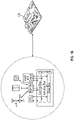
FIG. 1A shows a system for applying a powder bed fusion (PBF) process used to manufacture a pump inlet housing and filter according to one or more embodiments; -
FIG. 1B shows aspects of a controller utilized inFIG. 1A ; -
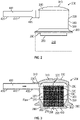
FIG. 2 shows a monolithic pump inlet housing and filter manufactured using a PBF process according to one or more embodiments; -
FIG. 3 shows a cross section of the monolithic pump inlet housing and filter ofFIG. 2 ; -
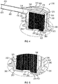
FIG. 4 shows a perspective view of the cross section of the monolithic pump inlet housing and filter ofFIG. 2 ; -
FIG. 5 shows a section of the cross section of the monolithic pump inlet housing and filter ofFIG. 4 ; -
FIG. 6 shows another exemplary monolithic pump inlet housing and filter using a PBF process according to one or more embodiments; -
FIG. 7 shows a cross section of the monolithic pump inlet housing and filter ofFIG. 6 ; -
FIG. 8 shows a perspective view of the cross section of the monolithic pump inlet housing and filter ofFIG. 6 ; -
FIG. 9 shows a section of the cross section of the monolithic pump inlet housing and filter ofFIG. 8 ; -
FIGS. 10-12 are flowcharts showing a method of fabricating the monolithic pump inlet housings and filter ofFIGS. 2 and6 according to one or more embodiments; and - A detailed description of one or more embodiments of the disclosed apparatus and method are presented herein by way of exemplification and not limitation with reference to the Figures.
- Pumps in fluid systems use filters so that contaminants are captured and not passed to the pump and then pumped downstream from the pump. The utilization of filters may minimize a reduction in performance and damage to downstream parts. The filter is typically an item that is insertable into a pump inlet housing. There are various drawbacks to having the filter as a separate item from the pump inlet housing. Thus, according to embodiments, the filter and pump inlet housing are formed as a monolithic part, e.g., utilizing additive manufacturing (AM), and specifically Powder bed fusion (PBF). That is, with AM and software computer aided design (CAD) technologies, it may be feasible to design and fabricate a pump inlet housing and filter as a monolithic structure utilizing powder bed fusion AM techniques. For example, the AM process may enable more flexibility in the design of the monolithic structure.
- Turning to
FIG. 1A , asystem 100 for performing PBF is generally shown and described. Thesystem 100 uses a high-energy power laser (laser) 110 to selectively melt or sinter a metallic powder that is located in thepowder bed 120. The processes utilize aplatform 125 to hold the powder and build upon. In a laser powder bed process, thelaser 110 is operationally connected via wired or wireless networks to acomputer 130 with an associatedcontroller 135. The laser beam from the laser passes through a system oflenses 140 and is reflected by amirror 150 onto theplatform 125. Themirror 150 is used to control the laser beam spot movement on the planar (x and y) directions on designed paths. After a layer of powder is selectively melted, theplatform 125 moves downward via action of abuild piston 160, a recoatingblade 170 or brush pushes another layer of fresh powder from apowder dispenser tank 180, which may be moved via apowder supply piston 185, to a top of the previously built surface, and the laser scanning process is repeated. According to an embodiment, aluminum may be the material utilized as the powder. Other materials may also be utilized depending on pressures, temperature and working fluids, e.g., steel, titanium, etc. Anoverflow container 190 may be provided to recover redundant powder once a layer has been spread. One ormore sensors 194 may be provided by which thecomputer 130 monitors progress of the PBF process. Thebuild chamber 195 of thesystem 100 is filled with an inert gas, argon in most cases, to avoid oxidization of the metal as it melts and resolidifies. - As shown in
FIG. 1B , thecontroller 135 identified herein may further include, in addition to a processor and non-volatile memory, one or more input and/or output (I/O) device interface(s) that are communicatively coupled via an onboard (local) interface to communicate among other devices. The onboard interface may include, for example but not limited to, an onboard system bus, including a control bus (for inter-device communications), an address bus (for physical addressing) and a data bus (for transferring data). That is, the system bus may enable the electronic communications between the processor, memory and I/O connections. The I/O connections may also include wired connections and/or wireless connections identified herein. The onboard interface may have additional elements, which are omitted for simplicity, such as controllers, buffers (caches), drivers, repeaters, and receivers to enable electronic communications. The memory may execute programs, access data, or lookup charts, or a combination of each, in furtherance of its processing, all of which may be stored in advance or received during execution of its processes by other computing devices, e.g., via a cloud service or other network connection with other processors. Embodiments can be in the form of processor-implemented processes and devices for practicing those processes, such as processor. Embodiments can also be in the form of computer code based modules, e.g., computer program code (e.g., computer program product) containing instructions embodied in tangible media (e.g., non-transitory computer readable medium), such as floppy diskettes, CD ROMs, hard drives, on processor registers as firmware, or any other non-transitory computer readable medium, wherein, when the computer program code is loaded into and executed by a computer, the computer becomes a device for practicing the embodiments. Embodiments can also be in the form of computer program code, for example, whether stored in a storage medium, loaded into and/or executed by a computer, or transmitted over some transmission medium, such as over electrical wiring or cabling, through fiber optics, or via electromagnetic radiation, wherein, when the computer program code is loaded into and executed by a computer, the computer becomes a device for practicing the exemplary embodiments. When implemented on a general-purpose microprocessor, the computer program code segments configure the microprocessor to create specific logic circuits. - Turning to
FIGS 10-12 , a flowchart shows a method of manufacturing a pair of disclosed pump inlet housings and respective filters 200 (FIGS. 2-5 ) and 200A (FIGS. 6-10 ) for a pump 210 (shown schematically inFIGS. 2 and6 ). The pump inlet housings andrespective filters FIG. 10 , as shown inblock 1010, for each of the pump inlet housings andrespective filters pump inlet housing 220 as a housing tubular shape. Thepump inlet housing 220 is defined to include aninlet aperture boundary 230 at a housingtop end 240 and anoutlet aperture boundary 250 at a housingbottom end 260. Alattice filter 270 is defined to be within eachpump inlet housing 220 between the housing top and bottom ends 240, 260. That is, the configuration of thepump inlet housing 220 is defined on a computer readable medium, such as disclosed below, which will be utilized the by the computer 130 (FIG. 1 ) to manufacture the pump inlet housings andrespective filters system 100 shown inFIG. 1 . As shown inblock 1020, the method includes performing an AM process to additively manufacture thepump inlet housings 220 and the respective lattice filters as integral (e.g., monolithic, unitary) structures. - Turning to
FIG. 11 , aspects of defining the pump inlet housing 220 (block 1010) of each pump inlet housing andrespective filter block 1010a, defining ahousing bottom surface 280 at the housingbottom end 260. Thehousing bottom surface 280 defines theoutlet aperture boundary 250 that forms anoutlet aperture 290. As shown inblock 1010b, defining thepump inlet housing 220 further includes defining ahousing exterior wall 300 that extends upwardly from thehousing bottom surface 280 to ahousing top surface 310 at the housingtop end 240. Thehousing exterior wall 300 defines aninner surface 320 to form atubular cavity 330 between the housing top andbottom surfaces inlet aperture boundary 230, that forms aninlet aperture 340, is defined through thehousing exterior wall 300 or thehousing top surface 310. - As shown in
block 1010c, thelattice filter 270 may be defined as a filter tubular shape. More specifically, alattice filter body 350 may extend upwardly from a filterbottom end 360, which may be located at the housingbottom end 260, to a filtertop end 370 that is adjacent the housingtop end 240. Afilter cap 375, at the filtertop end 370, may be configured as a lattice surface or a solid surface. A solid cap would require flow to enter thelattice filter 270 via other exposed perimeter surfaces of the filter, while a latticed cap would allow fluid to entire the filter via the top of the filter. - Turning to
FIG. 12 , further aspects of defining the pump inlet housing 220 (block 1010) for the pump inlet housings and filters 200, 200A are shown. As shown inblock 1010d, a mountingflange 380 is defined along anouter surface 390 of thehousing exterior wall 300. The mountingflange 380 is configured to mount the pump inlet housings andrespective filters pump 210. As shown inblock 1010e, aninlet conduit 400 may be integrally formed via the AM process with theinlet aperture boundary 230. Theinlet conduit 400 may include a conduitfirst end 405 that is integrally formed via the AM process with theinlet aperture boundary 230. Aconduit body 410 may extend away from the conduitfirst end 405 to a conduitsecond end 420. - The above description is common to the pump inlet housing and filter 200 shown in
FIGS. 2-5 and the pump inlet housing andfilter 200A shown inFIGS. 6-9 . - Turning now to the pump inlet housing and filter 200 shown in
FIGS. 2-5 , thepump inlet housing 220 may be formed with abase disk 430 at the housingbottom end 260. Thebase disk 430 defines theoutlet aperture boundary 250 having an outlet perimeter that is smaller than a housing wall perimeter defined by theinner surface 320 of thehousing exterior wall 300. Thelattice filter 270 may be integrally formed via the AM process with thebase disk 430. - An outer perimeter of the
lattice filter 270 may be smaller than the housing wall perimeter. Thefilter cap 375 of thelattice filter 270 may be spaced apart from the housingtop end 240. This enables flow into thelattice filter 270 along the path shown inFIG. 3 , e.g., through its outer perimeter. - As shown in
FIGS. 2-5 , the housing tubular shape of thepump inlet housing 220 and the filter tubular shape of thelattice filter 270 may both be cylindrical. However, other shapes are within the scope of the embodiments. - Turning now to the
FIGS. 6-9 , thelattice filter 270 may be formed via the AM process so that it is integral with theinner surface 320 of thehousing exterior wall 300 and conforms to a shape of inner surface of the housing exterior wall. A bottom portion 450 (FIG. 9 ) of theinner surface 320 of thehousing exterior wall 300 may form theoutlet aperture boundary 250. As shown in the figures, the housing shape of thepump inlet housing 220 may taper from the housingbottom end 260 to the housingtop end 240. - The taper shape (or sweep) of the pump inlet housing may be defined by a first rounded convex profile extending continuously between the mounting
flange 380 to the housingtop end 240. Theinlet aperture boundary 230 transitions to theinner surface 320 via a second rounded convex profile that is smaller than the first rounded convex profile. This configuration smoothly directs fluid flowing through the pump inlet housing along a curved path from the inlet conduit to the outlet aperture. This may reduce friction losses and pressure drops through the pump inlet housing. In addition, the filter may provide structural rigidity to enable the design ofFIGS. 6-9 which might otherwise fail under normal operational pressures. - A portion 460 (
FIGS. 7 and9 ) of theinner surface 320 of thehousing exterior wall 300, that is adjacent theinlet aperture boundary 230, curves inwardly. Thisportion 460 is intermediate of the housing top and bottom ends. This configuration locally reduces a flow area away from the outlet aperture while providing a relatively increased flow area at the outlet aperture, to provide desired flow characteristics into the pump. - The
filter cap 375 may be formed as a lattice surface and positioned at a skewed angle (neither parallel nor perpendicular) to theconduit body 410. This configuration assists in redirecting fluid flowing into thepump inlet housing 220 from theinlet conduit 400 so that the fluid flows toward theoutlet aperture boundary 250. This configuration, along with the shape of the pump inlet housing, may reduce friction loss and pressure drops through thepump inlet housing 220. - An outer filter portion 480 (
FIG. 9 ) of thelattice filter body 350, on a circumferentially opposing side relative to theinlet aperture boundary 230, may define a denser filter portion than aninner filter portion 490 on a circumferentially same side relative to the inlet aperture boundary. This configuration may locally increase flow resistance, which along with other aspects identified for thefilter housing 220, may provide desired flow characteristics into the pump. - As indicated, the
lattice filter 270 may be designed to provide structural support to thepump inlet housing 220, reducing the required structural characteristics of the pump inlet housing itself. That is, the structural integrity of thepump inlet housing 220 may be at least partially provided by thelattice filter 270 rather than being entirely provided from the design of the housing structure itself. - Thus, the disclosed embodiments reduce a complex assembly process to a process of growing a monolithic structure. Benefits of the disclosed embodiments include: 1) reducing part count and simplifying an overall assembly process because filter is part of the pump inlet housing; 2) providing for many different types of configurations, e.g., the pump inlet housing may have a greater sweep than machining may allow, and the shape, size and design of the filter may be varied and optimized for flow and pressure drop; and 3) utilizing the filter can as a structural support to the housing, being that the filter is integral to the housing, while still functioning as a filter.
- The terminology used herein is for the purpose of describing particular embodiments only and is not intended to be limiting of the present disclosure. As used herein, the singular forms "a", "an" and "the" are intended to include the plural forms as well, unless the context clearly indicates otherwise. It will be further understood that the terms "comprises" and/or "comprising," when used in this specification, specify the presence of stated features, integers, steps, operations, elements, and/or components, but do not preclude the presence or addition of one or more other features, integers, steps, operations, element components, and/or groups thereof.
- While the present disclosure has been described with reference to an exemplary embodiment or embodiments, it will be understood by those skilled in the art that various changes may be made without departing from the scope of the invention as defined by the claims. In addition, many modifications may be made to adapt a particular situation or material to the teachings of the present disclosure without departing from the scope of the claims. Therefore, it is intended that the present disclosure not be limited to the particular embodiment disclosed as the best mode contemplated for carrying out this present disclosure, but that the present disclosure will include all embodiments falling within the scope of the claims.
Claims (15)
- A method of manufacturing a pump inlet housing and filter for a pump assembly, wherein the pump inlet housing and filter are monolithic, the method comprising:defining a pump inlet housing (220) as a housing tubular shape with an inlet aperture boundary (230) at a housing top end (240), and an outlet aperture boundary (250) at a housing bottom end (260);defining a lattice filter (270) between the inlet and outlet aperture boundaries; andperforming an additive manufacturing, AM, process to additively manufacture the pump inlet housing and the lattice filter such that the lattice filter is integral with the pump inlet housing.
- The method of claim 1, wherein
the AM process comprises applying laser bed powder fusion. - The method of claim 1 or 2, wherein
defining the pump inlet housing includes defining:a housing bottom surface (280) at the housing bottom end (260), the housing bottom surface defining the outlet aperture boundary;a housing exterior wall (300) that extends upwardly from the housing bottom surface to a housing top surface (310) at the housing top end (240), wherein the housing exterior wall defines an inner surface (320) to form a tubular cavity (330) between the housing top and bottom surfaces,wherein the inlet aperture boundary is defined through the housing exterior wall or the housing top surface. - The method of claim 3, whereinthe lattice filter (270) is defined as a filter tubular shape and includes:a lattice filter body (350) that extends upwardly from a filter bottom end (360), located at the housing bottom end (260), to a filter top end (320) that is adjacent to the housing top end (240); anda filter cap (375), at the filter top end, that is a lattice surface or a solid surface; and optionally wherein:a mounting flange (380) is defined along an outer surface of the housing exterior wall, wherein the mounting flange is configured to mount the pump inlet housing to a pump housing.
- The method of any preceding claim, wherein
an inlet conduit (400) is integrally formed via the AM process with the inlet aperture boundary, which includes:a conduit first end (405) that is integrally formed via the AM process with the inlet aperture boundary; anda conduit body (410) that extends away from the conduit first end to a conduit second end (420). - The method of claim 5, wherein:the pump inlet housing is formed with a base disk (430) at the housing bottom end, wherein the base disk defines the outlet aperture boundary having an outlet perimeter that is smaller than a housing wall perimeter defined by the inner surface of the housing exterior wall; andwherein the lattice filter is integrally formed via the AM process with the base disk.
- The method of claim 6, wherein:an outer perimeter of the lattice filter is smaller than the housing wall perimeter; andthe filter cap of the lattice filter is spaced apart from the housing top end, and optionally wherein:
the housing tubular shape and the filter tubular shape are cylindrical. - The method of claim 5, wherein:the lattice filter is integrally formed via the AM process with the inner surface of the housing exterior and conforms to a shape of inner surface of the housing exterior wall; anda bottom portion of the inner surface of the housing exterior wall defines the outlet aperture boundary; and optionally wherein:
the pump inlet housing is formed with a housing shape that tapers from the housing bottom end to the housing top end. - The method of claim 8, wherein:the housing shape is defined by a first rounded convex profile extending continuously between the mounting flange to the housing top end; andthe inlet aperture boundary is formed to transition to the inner surface via a second rounded convex profile that is smaller than the first rounded convex profile.
- The method of claim 9, whereina portion (460) of the inner surface of the housing exterior wall, that is adjacent to the inlet aperture boundary, curves inwardly to thereby locally reduce flow area,wherein the portion of the inner surface being intermediate of the housing top and bottom ends.
- The method of claim 10, whereinthe filter cap is formed as the lattice surface and positioned at a skewed angle to the conduit body; and optionally whereina portion of the lattice filter on a circumferentially opposing side relative to the inlet aperture boundary defines a denser filter portion than a portion on a circumferentially same side relative to the inlet aperture boundary.
- An inlet housing for a pump assembly, wherein the pump inlet housing is monolithic and comprises:a pump inlet housing (220) having a housing tubular shape with an inlet aperture boundary (230) at a housing top end (240), and an outlet aperture boundary (250) at a housing bottom end (260);a lattice filter (270) that is integrally formed with the pump inlet housing via an additive manufacturing, AM, process, the lattice filter including the pump inlet housing between the inlet and outlet aperture boundaries.
- The pump inlet housing of claim 12, wherein
the pump inlet housing includes:a housing bottom surface (280) at the housing bottom end (260), the housing bottom surface defining the outlet aperture boundary; anda housing exterior wall (300) that extends upwardly from the housing bottom surface to a housing top surface (310) at the housing top end (240), wherein the housing exterior wall defines an inner surface (320) to form a tubular cavity (330) between the housing top and bottom surfaces,wherein the inlet aperture boundary is defined through the housing exterior wall or the housing top surface. - The pump inlet housing of claim 13, wherein
the lattice filter is defined as a filter tubular shape and includes:a lattice filter body (350) that extends upwardly from a filter bottom end (360), located at the housing bottom end, to a filter top end (370) that is adjacent to the housing top end; anda filter cap (375), at the filter top end, that is a lattice surface or a solid surface, and optionally wherein:
a mounting flange (380) is defined along an outer surface of the housing exterior wall, wherein the mounting flange is configured to mount the pump inlet housing to a pump housing. - The pump inlet housing of claim 14, wherein
an inlet conduit (400) is integrally formed via the AM process with the inlet aperture boundary, which includes:a conduit first end (405) that is integrally formed via the AM process with the inlet aperture boundary; anda conduit body (410) that extends away from the conduit first end to a conduit second end (420).
Applications Claiming Priority (1)
| Application Number | Priority Date | Filing Date | Title |
|---|---|---|---|
| US202163184425P | 2021-05-05 | 2021-05-05 |
Publications (2)
| Publication Number | Publication Date |
|---|---|
| EP4086464A1 true EP4086464A1 (en) | 2022-11-09 |
| EP4086464B1 EP4086464B1 (en) | 2025-06-25 |
Family
ID=81585721
Family Applications (1)
| Application Number | Title | Priority Date | Filing Date |
|---|---|---|---|
| EP22171845.5A Active EP4086464B1 (en) | 2021-05-05 | 2022-05-05 | Monolithic additively manufactured pump inlet housing and filter |
Country Status (2)
| Country | Link |
|---|---|
| US (1) | US12343664B2 (en) |
| EP (1) | EP4086464B1 (en) |
Citations (3)
| Publication number | Priority date | Publication date | Assignee | Title |
|---|---|---|---|---|
| US5511585A (en) * | 1994-03-31 | 1996-04-30 | The Lee Company | Method and device for providing fluid resistance within a flow passageway |
| US20200017231A1 (en) * | 2018-07-10 | 2020-01-16 | Hamilton Sundstrand Corporation | Heated pipe for liquid flows |
| DE102018119730A1 (en) * | 2018-08-14 | 2020-02-20 | Danfoss Power Solutions Gmbh & Co. Ohg | Improved fluid lines |
Family Cites Families (4)
| Publication number | Priority date | Publication date | Assignee | Title |
|---|---|---|---|---|
| US7093721B2 (en) * | 2003-09-03 | 2006-08-22 | Delaware Corporation Formation, Inc. | Filter assembly with sealed, magnetically coupled cleaning head actuator |
| BE1023324B1 (en) | 2015-08-06 | 2017-02-06 | Safran Aero Boosters Sa | TURBOMACHINE ENGINE OIL STRAINER |
| FR3049982B1 (en) | 2016-04-12 | 2020-01-17 | Zodiac Aerotechnics | METHOD OF MANUFACTURING A STRAINER, STRAINER, AND EJECTOR COMPRISING SUCH A STRAINER |
| US20200182207A1 (en) | 2018-12-11 | 2020-06-11 | Caterpillar Inc. | Sleeve for a filter assembly |
-
2022
- 2022-05-03 US US17/735,479 patent/US12343664B2/en active Active
- 2022-05-05 EP EP22171845.5A patent/EP4086464B1/en active Active
Patent Citations (3)
| Publication number | Priority date | Publication date | Assignee | Title |
|---|---|---|---|---|
| US5511585A (en) * | 1994-03-31 | 1996-04-30 | The Lee Company | Method and device for providing fluid resistance within a flow passageway |
| US20200017231A1 (en) * | 2018-07-10 | 2020-01-16 | Hamilton Sundstrand Corporation | Heated pipe for liquid flows |
| DE102018119730A1 (en) * | 2018-08-14 | 2020-02-20 | Danfoss Power Solutions Gmbh & Co. Ohg | Improved fluid lines |
Also Published As
| Publication number | Publication date |
|---|---|
| US20220355227A1 (en) | 2022-11-10 |
| US12343664B2 (en) | 2025-07-01 |
| EP4086464B1 (en) | 2025-06-25 |
Similar Documents
| Publication | Publication Date | Title |
|---|---|---|
| CN114730172B (en) | Computer-aided design method, computer-aided design system, and computer-readable medium for hybrid additive and subtractive manufacturing | |
| CN109070217B (en) | An additive machine that builds surfaces using rotation | |
| EP2781872B1 (en) | Heat exchanger design and fabrication | |
| US9597732B2 (en) | Flow restrictor assemblies including a monolithic flow restrictor and methods for manufacturing the same | |
| RU2754051C2 (en) | Delayed adaptation of end connections of the valve case in accordance with customer's requirements using additive industrial production | |
| US11193216B2 (en) | Methods and systems for electrochemical machining of articles formed by additive manufacturing | |
| CN109202087A (en) | The impeller for manufacturing the method for the impeller of rotary machine and being manufactured with such method | |
| EP4198320A1 (en) | Additively manufactured ejector pump | |
| US20170008084A1 (en) | Additive manufacturing of joining preforms | |
| CN105026125A (en) | Continuous feed 3D manufacturing | |
| RU2756763C2 (en) | Algorithm for predicting welding deformation resulting from connecting flanges to the end face of valve body casting by butt welding or socket welding | |
| CA3043721A1 (en) | Robotic arm assembly construction | |
| EP4086464B1 (en) | Monolithic additively manufactured pump inlet housing and filter | |
| WO2013160198A1 (en) | Method for manufacturing a component having an overhang by layer-wise buildup | |
| US10682704B2 (en) | Material extraction tool | |
| US11884025B2 (en) | Three-dimensional printer and methods for assembling parts via integration of additive and conventional manufacturing operations | |
| CN113953758B (en) | Control method, device and system of in-situ material-increasing repairing equipment and repairing method | |
| EP4194701A1 (en) | Pump filter with predetermined swirl | |
| JP7080903B2 (en) | Manufacturing method of turbomachinery vanes for aircraft using laminated molding | |
| CN107211557A (en) | The integrated liquid cooling of server system | |
| US20220168963A1 (en) | Erodible support structure for additively manufactured article and process therefor | |
| CN108637250B (en) | Aluminum alloy weight-reducing part forming method | |
| EP3799976A1 (en) | Changeable recoater approach angle | |
| CN114131041B (en) | System and method for estimating powder dosage in an additive manufacturing process | |
| EP3097334B1 (en) | Fuel fitting |
Legal Events
| Date | Code | Title | Description |
|---|---|---|---|
| PUAI | Public reference made under article 153(3) epc to a published international application that has entered the european phase |
Free format text: ORIGINAL CODE: 0009012 |
|
| STAA | Information on the status of an ep patent application or granted ep patent |
Free format text: STATUS: THE APPLICATION HAS BEEN PUBLISHED |
|
| AK | Designated contracting states |
Kind code of ref document: A1 Designated state(s): AL AT BE BG CH CY CZ DE DK EE ES FI FR GB GR HR HU IE IS IT LI LT LU LV MC MK MT NL NO PL PT RO RS SE SI SK SM TR |
|
| STAA | Information on the status of an ep patent application or granted ep patent |
Free format text: STATUS: REQUEST FOR EXAMINATION WAS MADE |
|
| 17P | Request for examination filed |
Effective date: 20230509 |
|
| RBV | Designated contracting states (corrected) |
Designated state(s): AL AT BE BG CH CY CZ DE DK EE ES FI FR GB GR HR HU IE IS IT LI LT LU LV MC MK MT NL NO PL PT RO RS SE SI SK SM TR |
|
| GRAP | Despatch of communication of intention to grant a patent |
Free format text: ORIGINAL CODE: EPIDOSNIGR1 |
|
| STAA | Information on the status of an ep patent application or granted ep patent |
Free format text: STATUS: GRANT OF PATENT IS INTENDED |
|
| INTG | Intention to grant announced |
Effective date: 20241218 |
|
| GRAS | Grant fee paid |
Free format text: ORIGINAL CODE: EPIDOSNIGR3 |
|
| GRAA | (expected) grant |
Free format text: ORIGINAL CODE: 0009210 |
|
| STAA | Information on the status of an ep patent application or granted ep patent |
Free format text: STATUS: THE PATENT HAS BEEN GRANTED |
|
| AK | Designated contracting states |
Kind code of ref document: B1 Designated state(s): AL AT BE BG CH CY CZ DE DK EE ES FI FR GB GR HR HU IE IS IT LI LT LU LV MC MK MT NL NO PL PT RO RS SE SI SK SM TR |
|
| REG | Reference to a national code |
Ref country code: GB Ref legal event code: FG4D |
|
| REG | Reference to a national code |
Ref country code: CH Ref legal event code: EP |
|
| REG | Reference to a national code |
Ref country code: CH Ref legal event code: EP |
|
| REG | Reference to a national code |
Ref country code: IE Ref legal event code: FG4D |
|
| REG | Reference to a national code |
Ref country code: DE Ref legal event code: R096 Ref document number: 602022016307 Country of ref document: DE |
|
| PG25 | Lapsed in a contracting state [announced via postgrant information from national office to epo] |
Ref country code: FI Free format text: LAPSE BECAUSE OF FAILURE TO SUBMIT A TRANSLATION OF THE DESCRIPTION OR TO PAY THE FEE WITHIN THE PRESCRIBED TIME-LIMIT Effective date: 20250625 |
|
| REG | Reference to a national code |
Ref country code: LT Ref legal event code: MG9D |
|
| PG25 | Lapsed in a contracting state [announced via postgrant information from national office to epo] |
Ref country code: GR Free format text: LAPSE BECAUSE OF FAILURE TO SUBMIT A TRANSLATION OF THE DESCRIPTION OR TO PAY THE FEE WITHIN THE PRESCRIBED TIME-LIMIT Effective date: 20250926 Ref country code: NO Free format text: LAPSE BECAUSE OF FAILURE TO SUBMIT A TRANSLATION OF THE DESCRIPTION OR TO PAY THE FEE WITHIN THE PRESCRIBED TIME-LIMIT Effective date: 20250925 |
|
| PG25 | Lapsed in a contracting state [announced via postgrant information from national office to epo] |
Ref country code: BG Free format text: LAPSE BECAUSE OF FAILURE TO SUBMIT A TRANSLATION OF THE DESCRIPTION OR TO PAY THE FEE WITHIN THE PRESCRIBED TIME-LIMIT Effective date: 20250625 |
|
| PG25 | Lapsed in a contracting state [announced via postgrant information from national office to epo] |
Ref country code: HR Free format text: LAPSE BECAUSE OF FAILURE TO SUBMIT A TRANSLATION OF THE DESCRIPTION OR TO PAY THE FEE WITHIN THE PRESCRIBED TIME-LIMIT Effective date: 20250625 |
|
| PG25 | Lapsed in a contracting state [announced via postgrant information from national office to epo] |
Ref country code: RS Free format text: LAPSE BECAUSE OF FAILURE TO SUBMIT A TRANSLATION OF THE DESCRIPTION OR TO PAY THE FEE WITHIN THE PRESCRIBED TIME-LIMIT Effective date: 20250925 |
|
| PG25 | Lapsed in a contracting state [announced via postgrant information from national office to epo] |
Ref country code: LV Free format text: LAPSE BECAUSE OF FAILURE TO SUBMIT A TRANSLATION OF THE DESCRIPTION OR TO PAY THE FEE WITHIN THE PRESCRIBED TIME-LIMIT Effective date: 20250625 |
|
| REG | Reference to a national code |
Ref country code: NL Ref legal event code: MP Effective date: 20250625 |
|
| PG25 | Lapsed in a contracting state [announced via postgrant information from national office to epo] |
Ref country code: NL Free format text: LAPSE BECAUSE OF FAILURE TO SUBMIT A TRANSLATION OF THE DESCRIPTION OR TO PAY THE FEE WITHIN THE PRESCRIBED TIME-LIMIT Effective date: 20250625 |
|
| PG25 | Lapsed in a contracting state [announced via postgrant information from national office to epo] |
Ref country code: PT Free format text: LAPSE BECAUSE OF FAILURE TO SUBMIT A TRANSLATION OF THE DESCRIPTION OR TO PAY THE FEE WITHIN THE PRESCRIBED TIME-LIMIT Effective date: 20251027 |
|
| REG | Reference to a national code |
Ref country code: AT Ref legal event code: MK05 Ref document number: 1806687 Country of ref document: AT Kind code of ref document: T Effective date: 20250625 |
|
| PG25 | Lapsed in a contracting state [announced via postgrant information from national office to epo] |
Ref country code: IS Free format text: LAPSE BECAUSE OF FAILURE TO SUBMIT A TRANSLATION OF THE DESCRIPTION OR TO PAY THE FEE WITHIN THE PRESCRIBED TIME-LIMIT Effective date: 20251025 |
|
| PG25 | Lapsed in a contracting state [announced via postgrant information from national office to epo] |
Ref country code: AT Free format text: LAPSE BECAUSE OF FAILURE TO SUBMIT A TRANSLATION OF THE DESCRIPTION OR TO PAY THE FEE WITHIN THE PRESCRIBED TIME-LIMIT Effective date: 20250625 Ref country code: SM Free format text: LAPSE BECAUSE OF FAILURE TO SUBMIT A TRANSLATION OF THE DESCRIPTION OR TO PAY THE FEE WITHIN THE PRESCRIBED TIME-LIMIT Effective date: 20250625 |
|
| PG25 | Lapsed in a contracting state [announced via postgrant information from national office to epo] |
Ref country code: CZ Free format text: LAPSE BECAUSE OF FAILURE TO SUBMIT A TRANSLATION OF THE DESCRIPTION OR TO PAY THE FEE WITHIN THE PRESCRIBED TIME-LIMIT Effective date: 20250625 |
|
| PG25 | Lapsed in a contracting state [announced via postgrant information from national office to epo] |
Ref country code: PL Free format text: LAPSE BECAUSE OF FAILURE TO SUBMIT A TRANSLATION OF THE DESCRIPTION OR TO PAY THE FEE WITHIN THE PRESCRIBED TIME-LIMIT Effective date: 20250625 |
|
| PG25 | Lapsed in a contracting state [announced via postgrant information from national office to epo] |
Ref country code: EE Free format text: LAPSE BECAUSE OF FAILURE TO SUBMIT A TRANSLATION OF THE DESCRIPTION OR TO PAY THE FEE WITHIN THE PRESCRIBED TIME-LIMIT Effective date: 20250625 |
|
| PG25 | Lapsed in a contracting state [announced via postgrant information from national office to epo] |
Ref country code: SK Free format text: LAPSE BECAUSE OF FAILURE TO SUBMIT A TRANSLATION OF THE DESCRIPTION OR TO PAY THE FEE WITHIN THE PRESCRIBED TIME-LIMIT Effective date: 20250625 |
|
| PG25 | Lapsed in a contracting state [announced via postgrant information from national office to epo] |
Ref country code: ES Free format text: LAPSE BECAUSE OF FAILURE TO SUBMIT A TRANSLATION OF THE DESCRIPTION OR TO PAY THE FEE WITHIN THE PRESCRIBED TIME-LIMIT Effective date: 20250625 |
|
| PG25 | Lapsed in a contracting state [announced via postgrant information from national office to epo] |
Ref country code: DK Free format text: LAPSE BECAUSE OF FAILURE TO SUBMIT A TRANSLATION OF THE DESCRIPTION OR TO PAY THE FEE WITHIN THE PRESCRIBED TIME-LIMIT Effective date: 20250625 |
|
| PG25 | Lapsed in a contracting state [announced via postgrant information from national office to epo] |
Ref country code: IT Free format text: LAPSE BECAUSE OF FAILURE TO SUBMIT A TRANSLATION OF THE DESCRIPTION OR TO PAY THE FEE WITHIN THE PRESCRIBED TIME-LIMIT Effective date: 20250625 |
|
| PLBE | No opposition filed within time limit |
Free format text: ORIGINAL CODE: 0009261 |
|
| STAA | Information on the status of an ep patent application or granted ep patent |
Free format text: STATUS: NO OPPOSITION FILED WITHIN TIME LIMIT |
|
| REG | Reference to a national code |
Ref country code: CH Ref legal event code: L10 Free format text: ST27 STATUS EVENT CODE: U-0-0-L10-L00 (AS PROVIDED BY THE NATIONAL OFFICE) Effective date: 20260507 |