EP4086461B1 - Fluid pump - Google Patents
Fluid pump Download PDFInfo
- Publication number
- EP4086461B1 EP4086461B1 EP22171398.5A EP22171398A EP4086461B1 EP 4086461 B1 EP4086461 B1 EP 4086461B1 EP 22171398 A EP22171398 A EP 22171398A EP 4086461 B1 EP4086461 B1 EP 4086461B1
- Authority
- EP
- European Patent Office
- Prior art keywords
- thermally conductive
- temperature sensor
- fluid pump
- fluid
- housing part
- Prior art date
- Legal status (The legal status is an assumption and is not a legal conclusion. Google has not performed a legal analysis and makes no representation as to the accuracy of the status listed.)
- Active
Links
Images




Classifications
-
- F—MECHANICAL ENGINEERING; LIGHTING; HEATING; WEAPONS; BLASTING
- F04—POSITIVE - DISPLACEMENT MACHINES FOR LIQUIDS; PUMPS FOR LIQUIDS OR ELASTIC FLUIDS
- F04C—ROTARY-PISTON, OR OSCILLATING-PISTON, POSITIVE-DISPLACEMENT MACHINES FOR LIQUIDS; ROTARY-PISTON, OR OSCILLATING-PISTON, POSITIVE-DISPLACEMENT PUMPS
- F04C28/00—Control of, monitoring of, or safety arrangements for, pumps or pumping installations specially adapted for elastic fluids
- F04C28/28—Safety arrangements; Monitoring
-
- F—MECHANICAL ENGINEERING; LIGHTING; HEATING; WEAPONS; BLASTING
- F04—POSITIVE - DISPLACEMENT MACHINES FOR LIQUIDS; PUMPS FOR LIQUIDS OR ELASTIC FLUIDS
- F04B—POSITIVE-DISPLACEMENT MACHINES FOR LIQUIDS; PUMPS
- F04B53/00—Component parts, details or accessories not provided for in, or of interest apart from, groups F04B1/00 - F04B23/00 or F04B39/00 - F04B47/00
- F04B53/16—Casings; Cylinders; Cylinder liners or heads; Fluid connections
-
- G—PHYSICS
- G01—MEASURING; TESTING
- G01K—MEASURING TEMPERATURE; MEASURING QUANTITY OF HEAT; THERMALLY-SENSITIVE ELEMENTS NOT OTHERWISE PROVIDED FOR
- G01K1/00—Details of thermometers not specially adapted for particular types of thermometer
- G01K1/14—Supports; Fastening devices; Arrangements for mounting thermometers in particular locations
-
- F—MECHANICAL ENGINEERING; LIGHTING; HEATING; WEAPONS; BLASTING
- F04—POSITIVE - DISPLACEMENT MACHINES FOR LIQUIDS; PUMPS FOR LIQUIDS OR ELASTIC FLUIDS
- F04B—POSITIVE-DISPLACEMENT MACHINES FOR LIQUIDS; PUMPS
- F04B51/00—Testing machines, pumps, or pumping installations
-
- F—MECHANICAL ENGINEERING; LIGHTING; HEATING; WEAPONS; BLASTING
- F04—POSITIVE - DISPLACEMENT MACHINES FOR LIQUIDS; PUMPS FOR LIQUIDS OR ELASTIC FLUIDS
- F04C—ROTARY-PISTON, OR OSCILLATING-PISTON, POSITIVE-DISPLACEMENT MACHINES FOR LIQUIDS; ROTARY-PISTON, OR OSCILLATING-PISTON, POSITIVE-DISPLACEMENT PUMPS
- F04C2/00—Rotary-piston machines or pumps
- F04C2/08—Rotary-piston machines or pumps of intermeshing-engagement type, i.e. with engagement of co-operating members similar to that of toothed gearing
- F04C2/10—Rotary-piston machines or pumps of intermeshing-engagement type, i.e. with engagement of co-operating members similar to that of toothed gearing of internal-axis type with the outer member having more teeth or tooth-equivalents, e.g. rollers, than the inner member
- F04C2/103—Rotary-piston machines or pumps of intermeshing-engagement type, i.e. with engagement of co-operating members similar to that of toothed gearing of internal-axis type with the outer member having more teeth or tooth-equivalents, e.g. rollers, than the inner member one member having simultaneously a rotational movement about its own axis and an orbital movement
-
- F—MECHANICAL ENGINEERING; LIGHTING; HEATING; WEAPONS; BLASTING
- F04—POSITIVE - DISPLACEMENT MACHINES FOR LIQUIDS; PUMPS FOR LIQUIDS OR ELASTIC FLUIDS
- F04C—ROTARY-PISTON, OR OSCILLATING-PISTON, POSITIVE-DISPLACEMENT MACHINES FOR LIQUIDS; ROTARY-PISTON, OR OSCILLATING-PISTON, POSITIVE-DISPLACEMENT PUMPS
- F04C29/00—Component parts, details or accessories of pumps or pumping installations, not provided for in groups F04C18/00 - F04C28/00
- F04C29/04—Heating; Cooling; Heat insulation
-
- G—PHYSICS
- G01—MEASURING; TESTING
- G01K—MEASURING TEMPERATURE; MEASURING QUANTITY OF HEAT; THERMALLY-SENSITIVE ELEMENTS NOT OTHERWISE PROVIDED FOR
- G01K1/00—Details of thermometers not specially adapted for particular types of thermometer
- G01K1/08—Protective devices, e.g. casings
-
- G—PHYSICS
- G01—MEASURING; TESTING
- G01K—MEASURING TEMPERATURE; MEASURING QUANTITY OF HEAT; THERMALLY-SENSITIVE ELEMENTS NOT OTHERWISE PROVIDED FOR
- G01K1/00—Details of thermometers not specially adapted for particular types of thermometer
- G01K1/16—Special arrangements for conducting heat from the object to the sensitive element
- G01K1/18—Special arrangements for conducting heat from the object to the sensitive element for reducing thermal inertia
-
- G—PHYSICS
- G01—MEASURING; TESTING
- G01K—MEASURING TEMPERATURE; MEASURING QUANTITY OF HEAT; THERMALLY-SENSITIVE ELEMENTS NOT OTHERWISE PROVIDED FOR
- G01K13/00—Thermometers specially adapted for specific purposes
- G01K13/02—Thermometers specially adapted for specific purposes for measuring temperature of moving fluids or granular materials capable of flow
- G01K13/026—Thermometers specially adapted for specific purposes for measuring temperature of moving fluids or granular materials capable of flow of moving liquids
-
- F—MECHANICAL ENGINEERING; LIGHTING; HEATING; WEAPONS; BLASTING
- F04—POSITIVE - DISPLACEMENT MACHINES FOR LIQUIDS; PUMPS FOR LIQUIDS OR ELASTIC FLUIDS
- F04B—POSITIVE-DISPLACEMENT MACHINES FOR LIQUIDS; PUMPS
- F04B2205/00—Fluid parameters
- F04B2205/10—Inlet temperature
-
- F—MECHANICAL ENGINEERING; LIGHTING; HEATING; WEAPONS; BLASTING
- F04—POSITIVE - DISPLACEMENT MACHINES FOR LIQUIDS; PUMPS FOR LIQUIDS OR ELASTIC FLUIDS
- F04B—POSITIVE-DISPLACEMENT MACHINES FOR LIQUIDS; PUMPS
- F04B2205/00—Fluid parameters
- F04B2205/11—Outlet temperature
-
- F—MECHANICAL ENGINEERING; LIGHTING; HEATING; WEAPONS; BLASTING
- F04—POSITIVE - DISPLACEMENT MACHINES FOR LIQUIDS; PUMPS FOR LIQUIDS OR ELASTIC FLUIDS
- F04C—ROTARY-PISTON, OR OSCILLATING-PISTON, POSITIVE-DISPLACEMENT MACHINES FOR LIQUIDS; ROTARY-PISTON, OR OSCILLATING-PISTON, POSITIVE-DISPLACEMENT PUMPS
- F04C2240/00—Components
- F04C2240/30—Casings or housings
-
- F—MECHANICAL ENGINEERING; LIGHTING; HEATING; WEAPONS; BLASTING
- F04—POSITIVE - DISPLACEMENT MACHINES FOR LIQUIDS; PUMPS FOR LIQUIDS OR ELASTIC FLUIDS
- F04C—ROTARY-PISTON, OR OSCILLATING-PISTON, POSITIVE-DISPLACEMENT MACHINES FOR LIQUIDS; ROTARY-PISTON, OR OSCILLATING-PISTON, POSITIVE-DISPLACEMENT PUMPS
- F04C2240/00—Components
- F04C2240/80—Other components
- F04C2240/81—Sensor, e.g. electronic sensor for control or monitoring
-
- F—MECHANICAL ENGINEERING; LIGHTING; HEATING; WEAPONS; BLASTING
- F04—POSITIVE - DISPLACEMENT MACHINES FOR LIQUIDS; PUMPS FOR LIQUIDS OR ELASTIC FLUIDS
- F04C—ROTARY-PISTON, OR OSCILLATING-PISTON, POSITIVE-DISPLACEMENT MACHINES FOR LIQUIDS; ROTARY-PISTON, OR OSCILLATING-PISTON, POSITIVE-DISPLACEMENT PUMPS
- F04C2270/00—Control; Monitoring or safety arrangements
- F04C2270/19—Temperature
Definitions
- the invention relates to a fluid pump with a housing, a fluid duct which is provided in the housing, and a temperature sensor which is assigned to the fluid duct in order to detect the temperature of a medium situated therein.
- Such a fluid pump may be used for supplying oil to a transmission or other components in a drive train.
- the temperature sensor is provided since the temperature has a major influence on the viscosity of the fluid to be pumped.
- the temperature sensor usually has a sensor element for temperature detection.
- a plastic element is here arranged between the sensor element and the fluid duct such that the sensor element is reliably protected from damage. The heat therefore flows from the fluid duct, via the plastic element, to the sensor element.
- plastic is a poor conductor of heat, this results in a rather slow reaction time of the temperature sensor.
- Document JP 2014 125955 A discloses a fluid pump having temperature sensors for sensing the temperature of the pumped medium, where the temperature sensors are located on a PCB inside a first housing part of the pump together with the stator of the electric motor of the pump.
- Document US 2019/339162 A1 discloses a fluid pump having a temperature sensor for sensing the temperature of the pumped medium, where the temperature sensor is located on the external surface of the pump housing, where a holding element of the temperature sensor projects from the external surface into a fluid duct of the pump.
- a fluid pump 10 which has an electric motor can be seen in Figure 1 .
- the electric motor is formed by a stator 12, which is arranged in a first housing part 16, and a first rotor 14.
- the rotor 14 is connected to a second rotor 20, which meshes with an annular gear 22 here, via a drive shaft 18.
- the second rotor 20 and the annular gear 22 are accommodated in a second housing part 24.
- the pump is a gerotor pump.
- Other embodiments are, however, possible, for example a centrifugal pump or a vane-type pump, if a constant delivery rate is required.
- the fluid pump 10 is attached to a transmission housing 26 and draws, for example, a hydraulic oil directly from the said transmission housing.
- a screen 28 is arranged on the suction side here.
- the fluid is discharged from the second rotor 20 to a fluid duct 30, from which it may be passed on to a distribution duct 32. From the said distribution duct, the fluid may be passed on, for example, to lubrication points in the transmission.
- a printed circuit board 34 which may be populated with components for actuating the electric motor, is accommodated in the first housing part 16.
- a sensor for detecting the position of the shaft 18 may also be arranged on the printed circuit board.
- the printed circuit board 34 is potted in the first housing part by means of a potting compound 36.
- a temperature sensor assembly 38 by means of which the temperature of the conveyed fluid is detected, is also attached to the printed circuit board 34.
- the temperature sensor assembly 38 has a carrier 40, which serves for attaching it in the housing of the fluid pump 10, and the actual temperature sensor 42.
- the latter has connection wires 44 which are electrically conductively connected to the stamped contacts 46.
- the stamped contacts 46 are accommodated in the carrier 40, for example injection-moulded there (see, for example, Figure 3 ).
- the end of the stamped contacts 46 which is opposite the temperature sensor 42 is in each case designed as a press-in contact 48 (see, for example, Figure 2 ) and is pressed into the printed circuit board 34.
- the temperature sensor 42 is arranged in a holding element 50, wherein a thermally conductive element 52 is arranged between the fluid duct 30 and the temperature sensor 42, and the thermally conductive element forms an outer wall of the holding element 50.
- the temperature sensor 42 is arranged as closely as possible to the inner wall of the thermally conductive element 52, and to be precise in that region of the holding element 50 which projects furthest into the fluid duct 30. Short heat conduction paths to the temperature sensor 42 consequently result and heat is input into the potting compound 36 on all sides, as a result of which changes in temperature can be detected more quickly.
Landscapes
- Engineering & Computer Science (AREA)
- Mechanical Engineering (AREA)
- General Engineering & Computer Science (AREA)
- Physics & Mathematics (AREA)
- General Physics & Mathematics (AREA)
- Details And Applications Of Rotary Liquid Pumps (AREA)
Description
- The invention relates to a fluid pump with a housing, a fluid duct which is provided in the housing, and a temperature sensor which is assigned to the fluid duct in order to detect the temperature of a medium situated therein.
- Such a fluid pump may be used for supplying oil to a transmission or other components in a drive train. In order to be able to regulate the flow of fluid in the desired manner, the temperature sensor is provided since the temperature has a major influence on the viscosity of the fluid to be pumped.
- The temperature sensor usually has a sensor element for temperature detection. A plastic element is here arranged between the sensor element and the fluid duct such that the sensor element is reliably protected from damage. The heat therefore flows from the fluid duct, via the plastic element, to the sensor element. However, because plastic is a poor conductor of heat, this results in a rather slow reaction time of the temperature sensor.
- Document
JP 2014 125955 A - Document
US 2019/339162 A1 discloses a fluid pump having a temperature sensor for sensing the temperature of the pumped medium, where the temperature sensor is located on the external surface of the pump housing, where a holding element of the temperature sensor projects from the external surface into a fluid duct of the pump. - The object of the invention is therefore to develop a fluid pump of the type mentioned at the beginning in such a way that a faster reaction time of the temperature sensor results.
- The object is achieved by providing a fluid pump according to claims 1-8.
- Further features and advantages of the invention will emerge from the following description and from the appended drawings, to which reference is made. In the drawings:
-
Figure 1 shows a view in section of a fluid pump according to the invention; -
Figure 2 shows a plan view of an embodiment according to the invention of a housing part with a temperature sensor assembly; -
Figure 3 shows a view in section along the plane III-III inFigure 2 ; -
Figure 4 shows a perspective view of the housing part inFigure 2 ; -
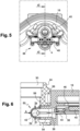
Figure 5 shows a plan view of a further embodiment according to the invention of a housing part with a temperature sensor assembly; -
Figure 6 shows a view in section along the plane VI-VI inFigure 5 ; -
Figure 7 shows a perspective view of the housing part inFigure 5 ; -
Figure 8 shows a plan view of an alternative embodiment according to the invention of a housing part with a temperature sensor assembly; -
Figure 9 shows a view in section along the plane VI-VI inFigure 8 ; and -
Figure 10 shows a perspective view of the housing part inFigure 8 . - A
fluid pump 10 which has an electric motor can be seen inFigure 1 . The electric motor is formed by astator 12, which is arranged in afirst housing part 16, and afirst rotor 14. Therotor 14 is connected to asecond rotor 20, which meshes with anannular gear 22 here, via adrive shaft 18. Thesecond rotor 20 and theannular gear 22 are accommodated in asecond housing part 24. - The
first housing part 16 and thesecond housing part 24 together form the housing of thefluid pump 10. - In the exemplary embodiment shown, the pump is a gerotor pump. Other embodiments are, however, possible, for example a centrifugal pump or a vane-type pump, if a constant delivery rate is required.
- The
fluid pump 10 is attached to atransmission housing 26 and draws, for example, a hydraulic oil directly from the said transmission housing. Ascreen 28 is arranged on the suction side here. - The fluid is discharged from the
second rotor 20 to afluid duct 30, from which it may be passed on to adistribution duct 32. From the said distribution duct, the fluid may be passed on, for example, to lubrication points in the transmission. - A printed
circuit board 34, which may be populated with components for actuating the electric motor, is accommodated in thefirst housing part 16. A sensor for detecting the position of theshaft 18 may also be arranged on the printed circuit board. - The printed
circuit board 34 is potted in the first housing part by means of apotting compound 36. - A
temperature sensor assembly 38, by means of which the temperature of the conveyed fluid is
detected, is also attached to the printedcircuit board 34. - The
temperature sensor assembly 38 has acarrier 40, which serves for attaching it in the housing of thefluid pump 10, and theactual temperature sensor 42. The latter hasconnection wires 44 which are electrically conductively connected to the stampedcontacts 46. The stampedcontacts 46 are accommodated in thecarrier 40, for example injection-moulded there (see, for example,Figure 3 ). - The end of the stamped
contacts 46 which is opposite thetemperature sensor 42 is in each case designed as a press-in contact 48 (see, for example,Figure 2 ) and is pressed into the printedcircuit board 34. - According to the invention, the
temperature sensor 42 is arranged in aholding element 50, wherein a thermallyconductive element 52 is arranged between thefluid duct 30 and thetemperature sensor 42, and the thermally conductive element forms an outer wall of theholding element 50. - A first embodiment of the
fluid pump 10 according to the invention is described below with reference toFigures 2 ,3 and 4 . Thetemperature sensor 42 is here arranged in aholding element 50, wherein the whole of theholding element 50 is formed by the thermallyconductive element 52. The thermallyconductive element 52 here consists of steel or an aluminium alloy and essentially has a U-shape in longitudinal section. - The thermally
conductive element 52 has, on the one hand, the function of absorbing the heat of the medium which is situated in thefluid duct 30 as quickly as possible and passing it on to thetemperature sensor 52 via thepotting compound 36. Metal, in particular steel or aluminium alloys, is better suited here than plastic because metals are better conductors of heat than plastic. As a result, changes in temperature can be detected more quickly by the temperature sensor, which in turn is advantageous for regulating the fluid flow. On the other hand, the thermallyconductive element 52 protects thetemperature sensor 42 additionally from damage caused by the medium in thefluid duct 30. - The
holding element 50 is additionally filled withpotting compound 36. Thepotting compound 36 fixes thetemperature sensor 42 inside theholding element 50 and additionally protects the latter from damage. - The
holding element 50 projects from an opening of thefirst housing part 16, through a duct opening 56 in thesecond housing part 24, into thefluid duct 30 and is pressed into thefirst housing part 16 via a fasteningflange 58. Other fastening options are also conceivable here. Thefirst housing part 16 is here placed on thesecond housing part 24. - The
temperature sensor 42 is arranged as closely as possible to the inner wall of the thermallyconductive element 52, and to be precise in that region of theholding element 50 which projects furthest into thefluid duct 30. Short heat conduction paths to thetemperature sensor 42 consequently result and heat is input into thepotting compound 36 on all sides, as a result of which changes in temperature can be detected more quickly. - A further embodiment of the
fluid pump 10 according to the invention is shown inFigures 5, 6 and7 . Because the fundamental principle corresponds to that of the first embodiment, only the differences are described in detail. - The difference from the first embodiment consists in the
holding element 50 here taking the form of a composite component consisting of a thermallyconductive element 52 and aplastic part 54. - The
plastic part 54 here takes the form of a protrusion with a through opening on thefirst housing part 16 and projects through the duct opening 56 into thefluid duct 30. - The
temperature sensor 42 here projects through the through opening from theplastic part 54. That part of thetemperature sensor 42 which projects from theplastic part 54 is surrounded by the thermallyconductive element 52. - The thermally
conductive element 52 here takes the form of an injected cover but other fastening options are also conceivable. In this exemplary embodiment, the thermallyconductive element 52 is injected over thefastening flange 58 into theplastic part 54. -
Figures 8 ,9 and 10 show an alternative embodiment. The holdingelement 50 is also here a composite component consisting of the thermallyconductive element 52 and aplastic part 54. - The difference from the previous embodiment is that the thermally
conductive element 52 is here designed as a cap which is placed on theplastic part 54. In this exemplary embodiment, the thermallyconductive element 52 is, more precisely, pressed onto theplastic part 54, wherein here too other fastening options such as, for example, locking via latching tabs are conceivable. - The
plastic part 54 here too takes the form of a protrusion with a through opening. However, thetemperature sensor 42 here does not project from the protrusion such that the thermallyconductive element 52 is situated on only one side between thetemperature sensor 42 and the fluid duct. In contrast, in the two previous embodiments, the thermally conductive element is situated on all sides between thetemperature sensor 42 and thefluid duct 30. This is illustrated inFigures 3 ,6 and9 . In the embodiments according toFigures 3 and6 , thetemperature sensor 42 can absorb the heat from all sides (A, B, C) quickly via the thermallyconductive element 52. In the embodiment according toFigure 9 , this takes place only from side A because at sides B and C theplastic part 54 is situated between thefluid duct 30 and thetemperature sensor 42.
Claims (8)
- Fluid pump (10) comprising a housing formed by a first housing part (16) and a second housing part (24), an electric motor formed by a stator (12) and a rotor (14), the stator (12) being arranged in the first housing part (16), a fluid duct (30) provided in the second housing part (24), a temperature sensor (42) assigned to the fluid duct (30) in order to detect the temperature of a medium situated therein, wherein the temperature sensor (42) is arranged in a holding element (50), a metal thermally conductive element (52) is arranged between the fluid duct (30) and the temperature sensor (42) and forms an outer wall of the holding element (50), characterized in that the holding element (50) is provided on the first housing part (16) which is placed on the second housing part (24), wherein the holding element (50) projects into the fluid duct (30).
- Fluid pump (10) according to claim 1, characterized in that the holding element (50) is a composite component consisting of a plastic part (54) and the thermally conductive element (52).
- Fluid pump (10) according to claim 2, characterized in that the thermally conductive element (52) takes the form of a cap which is placed on the plastic part (54).
- Fluid pump (10) according to claim 2, characterized in that the thermally conductive element (52) takes the form of an injected cover.
- Fluid pump (10) according to claim 1, characterized in that the thermally conductive element (52) forms the holding element (50).
- Fluid pump (10) according to one of claims 1 to 5, characterized in that the holding element (50) is filled with potting compound (36).
- Fluid pump (10) according to one of the preceding claims, characterized in that the thermally conductive element (52) is made of steel.
- Fluid pump according to one of claims 1 to 6, characterized in that the thermally conductive element (52) is made from an aluminium alloy.
Applications Claiming Priority (1)
| Application Number | Priority Date | Filing Date | Title |
|---|---|---|---|
| DE102021111975.8A DE102021111975A1 (en) | 2021-05-07 | 2021-05-07 | liquid pump |
Publications (2)
| Publication Number | Publication Date |
|---|---|
| EP4086461A1 EP4086461A1 (en) | 2022-11-09 |
| EP4086461B1 true EP4086461B1 (en) | 2025-03-12 |
Family
ID=81580067
Family Applications (1)
| Application Number | Title | Priority Date | Filing Date |
|---|---|---|---|
| EP22171398.5A Active EP4086461B1 (en) | 2021-05-07 | 2022-05-03 | Fluid pump |
Country Status (4)
| Country | Link |
|---|---|
| US (1) | US11746787B2 (en) |
| EP (1) | EP4086461B1 (en) |
| CN (1) | CN115389036A (en) |
| DE (1) | DE102021111975A1 (en) |
Families Citing this family (1)
| Publication number | Priority date | Publication date | Assignee | Title |
|---|---|---|---|---|
| CN115726959A (en) * | 2021-08-28 | 2023-03-03 | 株式会社三国 | Liquid pump device |
Citations (1)
| Publication number | Priority date | Publication date | Assignee | Title |
|---|---|---|---|---|
| JP2014125955A (en) * | 2012-12-26 | 2014-07-07 | Asmo Co Ltd | Electric pump |
Family Cites Families (23)
| Publication number | Priority date | Publication date | Assignee | Title |
|---|---|---|---|---|
| EP0539944A3 (en) | 1991-10-31 | 1993-08-04 | Eaton Corporation | Expansion valve and temperature sensing assembly therefor |
| JPH07324988A (en) | 1994-05-31 | 1995-12-12 | Sanyo Electric Co Ltd | Closed type compressor |
| DE19700965C1 (en) | 1997-01-14 | 1998-06-04 | Grundfos As | Sensor arrangement |
| DE10038550A1 (en) | 1999-09-13 | 2001-05-03 | Mannesmann Vdo Ag | pump |
| DE10029186C2 (en) | 2000-06-19 | 2002-04-25 | Heraeus Electro Nite Int | Temperature-measuring device |
| JP4041018B2 (en) * | 2003-06-25 | 2008-01-30 | Tdk株式会社 | Temperature sensor |
| JP4569638B2 (en) * | 2007-01-31 | 2010-10-27 | 株式会社デンソー | Temperature sensor |
| US8491184B2 (en) | 2007-02-27 | 2013-07-23 | Deka Products Limited Partnership | Sensor apparatus systems, devices and methods |
| DE102007011673A1 (en) | 2007-03-09 | 2008-09-11 | Bayerische Motoren Werke Aktiengesellschaft | Coolant regulator and method for its production |
| JP4274284B2 (en) * | 2007-05-02 | 2009-06-03 | ダイキン工業株式会社 | Compressor |
| US8496377B2 (en) * | 2007-12-31 | 2013-07-30 | Covidien Lp | Thermometer having molded probe component |
| GB2486007B (en) * | 2010-12-01 | 2017-05-10 | Itt Mfg Enterprises Inc | Sliding vane pump |
| US8523432B2 (en) | 2011-02-04 | 2013-09-03 | Honeywell International Inc. | Thermally isolated temperature sensor |
| CN203053582U (en) | 2012-12-22 | 2013-07-10 | 芜湖博耐尔汽车电气系统有限公司 | Evaporator temperature sensor |
| DE102014005818A1 (en) | 2014-04-24 | 2015-10-29 | Voss Automotive Gmbh | Connecting device, method for producing a connecting device, measuring device and method for producing a measuring device |
| EP3112830B1 (en) * | 2015-07-01 | 2018-08-22 | Sensata Technologies, Inc. | Temperature sensor and method for the production of a temperature sensor |
| GB2552447B (en) * | 2016-04-06 | 2019-06-12 | Qhi Group Ltd | Fault monitoring systems and methods for detecting connectivity faults |
| DE102016123409A1 (en) | 2016-12-05 | 2018-06-07 | Miele & Cie. Kg | Pump, in particular for a water-conducting household appliance such as in particular a washing machine |
| WO2018122016A1 (en) | 2016-12-30 | 2018-07-05 | Grundfos Holding A/S | Sensor assembly and method for fault detection in pumps and pump assembly comprising such sensor assembly |
| EP3779199B1 (en) | 2018-03-30 | 2024-11-27 | Daikin Industries, Ltd. | Refrigeration cycle device |
| DE102018208853A1 (en) | 2018-06-05 | 2019-12-05 | Magna Powertrain Bad Homburg GmbH | pump |
| DE102018008986A1 (en) | 2018-11-15 | 2020-05-20 | Diehl Ako Stiftung & Co. Kg | Temperature detection device |
| DE202019100671U1 (en) | 2019-02-05 | 2019-02-13 | Jumo Gmbh & Co. Kg | Smart fitting |
-
2021
- 2021-05-07 DE DE102021111975.8A patent/DE102021111975A1/en active Pending
-
2022
- 2022-04-26 US US17/660,679 patent/US11746787B2/en active Active
- 2022-05-03 EP EP22171398.5A patent/EP4086461B1/en active Active
- 2022-05-07 CN CN202210492094.3A patent/CN115389036A/en active Pending
Patent Citations (1)
| Publication number | Priority date | Publication date | Assignee | Title |
|---|---|---|---|---|
| JP2014125955A (en) * | 2012-12-26 | 2014-07-07 | Asmo Co Ltd | Electric pump |
Also Published As
| Publication number | Publication date |
|---|---|
| EP4086461A1 (en) | 2022-11-09 |
| US20220381244A1 (en) | 2022-12-01 |
| DE102021111975A1 (en) | 2022-11-10 |
| US11746787B2 (en) | 2023-09-05 |
| CN115389036A (en) | 2022-11-25 |
Similar Documents
| Publication | Publication Date | Title |
|---|---|---|
| JP3222140B2 (en) | Transmission control system for automobile | |
| CN113389722B (en) | Liquid Pumps | |
| CN101584257B (en) | Standardized electronics housing having modular contact partners | |
| US9642266B2 (en) | Electronic module for operation in a transmission | |
| US8157542B2 (en) | Brushless motor fuel pump with control electronics arrangement | |
| JP6576268B2 (en) | Electric drive | |
| US20160211727A1 (en) | Motor assembly | |
| US10869398B2 (en) | Control module for actuating at least one electrically operable actuator | |
| US7983054B2 (en) | Compact control device for a motor vehicle | |
| CN113853837A (en) | Electronic control device | |
| EP3588034B1 (en) | Oil temperature sensor | |
| EP4086461A1 (en) | Fluid pump | |
| CN111316505B (en) | circuit device | |
| CN110383960B (en) | Electronic control module and method for manufacturing electronic control module | |
| CN105407664A (en) | Pcb Arrangement With Two Interconnected Printed Circuit Boards And Chip Protection | |
| US7080575B2 (en) | Mechatronic transmission control | |
| CN116647082A (en) | motor stator | |
| CN115726959A (en) | Liquid pump device | |
| CN110521063A (en) | Electrical contact device | |
| KR20210015960A (en) | Electric actuator | |
| CN109642658B (en) | Non-contact inhibitor switch | |
| CN108062967B (en) | Condensation-preventing structure of sensor | |
| CN112788846B (en) | Electronic module and method for manufacturing an electronic module | |
| EP4386178B1 (en) | Fluid pump | |
| US10998656B2 (en) | Electrical assembly |
Legal Events
| Date | Code | Title | Description |
|---|---|---|---|
| PUAI | Public reference made under article 153(3) epc to a published international application that has entered the european phase |
Free format text: ORIGINAL CODE: 0009012 |
|
| STAA | Information on the status of an ep patent application or granted ep patent |
Free format text: STATUS: REQUEST FOR EXAMINATION WAS MADE |
|
| 17P | Request for examination filed |
Effective date: 20220503 |
|
| AK | Designated contracting states |
Kind code of ref document: A1 Designated state(s): AL AT BE BG CH CY CZ DE DK EE ES FI FR GB GR HR HU IE IS IT LI LT LU LV MC MK MT NL NO PL PT RO RS SE SI SK SM TR |
|
| P01 | Opt-out of the competence of the unified patent court (upc) registered |
Effective date: 20230629 |
|
| STAA | Information on the status of an ep patent application or granted ep patent |
Free format text: STATUS: EXAMINATION IS IN PROGRESS |
|
| 17Q | First examination report despatched |
Effective date: 20240125 |
|
| RAP1 | Party data changed (applicant data changed or rights of an application transferred) |
Owner name: VALEO POWERTRAIN GMBH |
|
| GRAP | Despatch of communication of intention to grant a patent |
Free format text: ORIGINAL CODE: EPIDOSNIGR1 |
|
| STAA | Information on the status of an ep patent application or granted ep patent |
Free format text: STATUS: GRANT OF PATENT IS INTENDED |
|
| INTG | Intention to grant announced |
Effective date: 20241223 |
|
| GRAS | Grant fee paid |
Free format text: ORIGINAL CODE: EPIDOSNIGR3 |
|
| GRAA | (expected) grant |
Free format text: ORIGINAL CODE: 0009210 |
|
| STAA | Information on the status of an ep patent application or granted ep patent |
Free format text: STATUS: THE PATENT HAS BEEN GRANTED |
|
| AK | Designated contracting states |
Kind code of ref document: B1 Designated state(s): AL AT BE BG CH CY CZ DE DK EE ES FI FR GB GR HR HU IE IS IT LI LT LU LV MC MK MT NL NO PL PT RO RS SE SI SK SM TR |
|
| REG | Reference to a national code |
Ref country code: GB Ref legal event code: FG4D |
|
| REG | Reference to a national code |
Ref country code: CH Ref legal event code: EP |
|
| REG | Reference to a national code |
Ref country code: DE Ref legal event code: R096 Ref document number: 602022011602 Country of ref document: DE |
|
| REG | Reference to a national code |
Ref country code: IE Ref legal event code: FG4D |
|
| PG25 | Lapsed in a contracting state [announced via postgrant information from national office to epo] |
Ref country code: RS Free format text: LAPSE BECAUSE OF FAILURE TO SUBMIT A TRANSLATION OF THE DESCRIPTION OR TO PAY THE FEE WITHIN THE PRESCRIBED TIME-LIMIT Effective date: 20250612 |
|
| PG25 | Lapsed in a contracting state [announced via postgrant information from national office to epo] |
Ref country code: FI Free format text: LAPSE BECAUSE OF FAILURE TO SUBMIT A TRANSLATION OF THE DESCRIPTION OR TO PAY THE FEE WITHIN THE PRESCRIBED TIME-LIMIT Effective date: 20250312 |
|
| PGFP | Annual fee paid to national office [announced via postgrant information from national office to epo] |
Ref country code: DE Payment date: 20250513 Year of fee payment: 4 |
|
| PG25 | Lapsed in a contracting state [announced via postgrant information from national office to epo] |
Ref country code: ES Free format text: LAPSE BECAUSE OF FAILURE TO SUBMIT A TRANSLATION OF THE DESCRIPTION OR TO PAY THE FEE WITHIN THE PRESCRIBED TIME-LIMIT Effective date: 20250312 |
|
| REG | Reference to a national code |
Ref country code: LT Ref legal event code: MG9D |
|
| PG25 | Lapsed in a contracting state [announced via postgrant information from national office to epo] |
Ref country code: NO Free format text: LAPSE BECAUSE OF FAILURE TO SUBMIT A TRANSLATION OF THE DESCRIPTION OR TO PAY THE FEE WITHIN THE PRESCRIBED TIME-LIMIT Effective date: 20250612 |
|
| PG25 | Lapsed in a contracting state [announced via postgrant information from national office to epo] |
Ref country code: HR Free format text: LAPSE BECAUSE OF FAILURE TO SUBMIT A TRANSLATION OF THE DESCRIPTION OR TO PAY THE FEE WITHIN THE PRESCRIBED TIME-LIMIT Effective date: 20250312 |
|
| REG | Reference to a national code |
Ref country code: NL Ref legal event code: MP Effective date: 20250312 |
|
| PG25 | Lapsed in a contracting state [announced via postgrant information from national office to epo] |
Ref country code: LV Free format text: LAPSE BECAUSE OF FAILURE TO SUBMIT A TRANSLATION OF THE DESCRIPTION OR TO PAY THE FEE WITHIN THE PRESCRIBED TIME-LIMIT Effective date: 20250312 |
|
| PGFP | Annual fee paid to national office [announced via postgrant information from national office to epo] |
Ref country code: FR Payment date: 20250530 Year of fee payment: 4 |
|
| PG25 | Lapsed in a contracting state [announced via postgrant information from national office to epo] |
Ref country code: BG Free format text: LAPSE BECAUSE OF FAILURE TO SUBMIT A TRANSLATION OF THE DESCRIPTION OR TO PAY THE FEE WITHIN THE PRESCRIBED TIME-LIMIT Effective date: 20250312 Ref country code: GR Free format text: LAPSE BECAUSE OF FAILURE TO SUBMIT A TRANSLATION OF THE DESCRIPTION OR TO PAY THE FEE WITHIN THE PRESCRIBED TIME-LIMIT Effective date: 20250613 |
|
| REG | Reference to a national code |
Ref country code: AT Ref legal event code: MK05 Ref document number: 1775195 Country of ref document: AT Kind code of ref document: T Effective date: 20250312 |
|
| PG25 | Lapsed in a contracting state [announced via postgrant information from national office to epo] |
Ref country code: NL Free format text: LAPSE BECAUSE OF FAILURE TO SUBMIT A TRANSLATION OF THE DESCRIPTION OR TO PAY THE FEE WITHIN THE PRESCRIBED TIME-LIMIT Effective date: 20250312 |
|
| PG25 | Lapsed in a contracting state [announced via postgrant information from national office to epo] |
Ref country code: SE Free format text: LAPSE BECAUSE OF FAILURE TO SUBMIT A TRANSLATION OF THE DESCRIPTION OR TO PAY THE FEE WITHIN THE PRESCRIBED TIME-LIMIT Effective date: 20250312 |
|
| PG25 | Lapsed in a contracting state [announced via postgrant information from national office to epo] |
Ref country code: SM Free format text: LAPSE BECAUSE OF FAILURE TO SUBMIT A TRANSLATION OF THE DESCRIPTION OR TO PAY THE FEE WITHIN THE PRESCRIBED TIME-LIMIT Effective date: 20250312 |
|
| PG25 | Lapsed in a contracting state [announced via postgrant information from national office to epo] |
Ref country code: PT Free format text: LAPSE BECAUSE OF FAILURE TO SUBMIT A TRANSLATION OF THE DESCRIPTION OR TO PAY THE FEE WITHIN THE PRESCRIBED TIME-LIMIT Effective date: 20250714 |
|
| PG25 | Lapsed in a contracting state [announced via postgrant information from national office to epo] |
Ref country code: PL Free format text: LAPSE BECAUSE OF FAILURE TO SUBMIT A TRANSLATION OF THE DESCRIPTION OR TO PAY THE FEE WITHIN THE PRESCRIBED TIME-LIMIT Effective date: 20250312 Ref country code: IT Free format text: LAPSE BECAUSE OF FAILURE TO SUBMIT A TRANSLATION OF THE DESCRIPTION OR TO PAY THE FEE WITHIN THE PRESCRIBED TIME-LIMIT Effective date: 20250312 |
|
| PG25 | Lapsed in a contracting state [announced via postgrant information from national office to epo] |
Ref country code: AT Free format text: LAPSE BECAUSE OF FAILURE TO SUBMIT A TRANSLATION OF THE DESCRIPTION OR TO PAY THE FEE WITHIN THE PRESCRIBED TIME-LIMIT Effective date: 20250312 |
|
| PG25 | Lapsed in a contracting state [announced via postgrant information from national office to epo] |
Ref country code: EE Free format text: LAPSE BECAUSE OF FAILURE TO SUBMIT A TRANSLATION OF THE DESCRIPTION OR TO PAY THE FEE WITHIN THE PRESCRIBED TIME-LIMIT Effective date: 20250312 Ref country code: CZ Free format text: LAPSE BECAUSE OF FAILURE TO SUBMIT A TRANSLATION OF THE DESCRIPTION OR TO PAY THE FEE WITHIN THE PRESCRIBED TIME-LIMIT Effective date: 20250312 |
|
| PG25 | Lapsed in a contracting state [announced via postgrant information from national office to epo] |
Ref country code: RO Free format text: LAPSE BECAUSE OF FAILURE TO SUBMIT A TRANSLATION OF THE DESCRIPTION OR TO PAY THE FEE WITHIN THE PRESCRIBED TIME-LIMIT Effective date: 20250312 |
|
| PG25 | Lapsed in a contracting state [announced via postgrant information from national office to epo] |
Ref country code: SK Free format text: LAPSE BECAUSE OF FAILURE TO SUBMIT A TRANSLATION OF THE DESCRIPTION OR TO PAY THE FEE WITHIN THE PRESCRIBED TIME-LIMIT Effective date: 20250312 |
|
| PG25 | Lapsed in a contracting state [announced via postgrant information from national office to epo] |
Ref country code: IS Free format text: LAPSE BECAUSE OF FAILURE TO SUBMIT A TRANSLATION OF THE DESCRIPTION OR TO PAY THE FEE WITHIN THE PRESCRIBED TIME-LIMIT Effective date: 20250712 |
|
| REG | Reference to a national code |
Ref country code: DE Ref legal event code: R097 Ref document number: 602022011602 Country of ref document: DE |
|
| REG | Reference to a national code |
Ref country code: CH Ref legal event code: H13 Free format text: ST27 STATUS EVENT CODE: U-0-0-H10-H13 (AS PROVIDED BY THE NATIONAL OFFICE) Effective date: 20251223 |
|
| PG25 | Lapsed in a contracting state [announced via postgrant information from national office to epo] |
Ref country code: DK Free format text: LAPSE BECAUSE OF FAILURE TO SUBMIT A TRANSLATION OF THE DESCRIPTION OR TO PAY THE FEE WITHIN THE PRESCRIBED TIME-LIMIT Effective date: 20250312 |
|
| PG25 | Lapsed in a contracting state [announced via postgrant information from national office to epo] |
Ref country code: LU Free format text: LAPSE BECAUSE OF NON-PAYMENT OF DUE FEES Effective date: 20250503 |
|
| PLBE | No opposition filed within time limit |
Free format text: ORIGINAL CODE: 0009261 |
|
| STAA | Information on the status of an ep patent application or granted ep patent |
Free format text: STATUS: NO OPPOSITION FILED WITHIN TIME LIMIT |
|
| PG25 | Lapsed in a contracting state [announced via postgrant information from national office to epo] |
Ref country code: CH Free format text: LAPSE BECAUSE OF NON-PAYMENT OF DUE FEES Effective date: 20250531 |
|
| REG | Reference to a national code |
Ref country code: CH Ref legal event code: L10 Free format text: ST27 STATUS EVENT CODE: U-0-0-L10-L00 (AS PROVIDED BY THE NATIONAL OFFICE) Effective date: 20260121 |
|
| REG | Reference to a national code |
Ref country code: BE Ref legal event code: MM Effective date: 20250531 |
|
| PG25 | Lapsed in a contracting state [announced via postgrant information from national office to epo] |
Ref country code: MC Free format text: LAPSE BECAUSE OF FAILURE TO SUBMIT A TRANSLATION OF THE DESCRIPTION OR TO PAY THE FEE WITHIN THE PRESCRIBED TIME-LIMIT Effective date: 20250312 |
|
| 26N | No opposition filed |
Effective date: 20251215 |
|
| PG25 | Lapsed in a contracting state [announced via postgrant information from national office to epo] |
Ref country code: IE Free format text: LAPSE BECAUSE OF NON-PAYMENT OF DUE FEES Effective date: 20250503 |
|
| PG25 | Lapsed in a contracting state [announced via postgrant information from national office to epo] |
Ref country code: BE Free format text: LAPSE BECAUSE OF NON-PAYMENT OF DUE FEES Effective date: 20250531 |