EP4086444A1 - Integrated fuel cell and engine combustor assembly - Google Patents
Integrated fuel cell and engine combustor assembly Download PDFInfo
- Publication number
- EP4086444A1 EP4086444A1 EP22167870.9A EP22167870A EP4086444A1 EP 4086444 A1 EP4086444 A1 EP 4086444A1 EP 22167870 A EP22167870 A EP 22167870A EP 4086444 A1 EP4086444 A1 EP 4086444A1
- Authority
- EP
- European Patent Office
- Prior art keywords
- fuel
- fuel cell
- combustor
- cell stack
- partial oxidation
- Prior art date
- Legal status (The legal status is an assumption and is not a legal conclusion. Google has not performed a legal analysis and makes no representation as to the accuracy of the status listed.)
- Pending
Links
Images

Classifications
-
- F—MECHANICAL ENGINEERING; LIGHTING; HEATING; WEAPONS; BLASTING
- F02—COMBUSTION ENGINES; HOT-GAS OR COMBUSTION-PRODUCT ENGINE PLANTS
- F02C—GAS-TURBINE PLANTS; AIR INTAKES FOR JET-PROPULSION PLANTS; CONTROLLING FUEL SUPPLY IN AIR-BREATHING JET-PROPULSION PLANTS
- F02C6/00—Plural gas-turbine plants; Combinations of gas-turbine plants with other apparatus; Adaptations of gas-turbine plants for special use
-
- F—MECHANICAL ENGINEERING; LIGHTING; HEATING; WEAPONS; BLASTING
- F23—COMBUSTION APPARATUS; COMBUSTION PROCESSES
- F23R—GENERATING COMBUSTION PRODUCTS OF HIGH PRESSURE OR HIGH VELOCITY, e.g. GAS-TURBINE COMBUSTION CHAMBERS
- F23R3/00—Continuous combustion chambers using liquid or gaseous fuel
- F23R3/40—Continuous combustion chambers using liquid or gaseous fuel characterised by the use of catalytic means
-
- F—MECHANICAL ENGINEERING; LIGHTING; HEATING; WEAPONS; BLASTING
- F02—COMBUSTION ENGINES; HOT-GAS OR COMBUSTION-PRODUCT ENGINE PLANTS
- F02C—GAS-TURBINE PLANTS; AIR INTAKES FOR JET-PROPULSION PLANTS; CONTROLLING FUEL SUPPLY IN AIR-BREATHING JET-PROPULSION PLANTS
- F02C3/00—Gas-turbine plants characterised by the use of combustion products as the working fluid
- F02C3/04—Gas-turbine plants characterised by the use of combustion products as the working fluid having a turbine driving a compressor
-
- F—MECHANICAL ENGINEERING; LIGHTING; HEATING; WEAPONS; BLASTING
- F02—COMBUSTION ENGINES; HOT-GAS OR COMBUSTION-PRODUCT ENGINE PLANTS
- F02C—GAS-TURBINE PLANTS; AIR INTAKES FOR JET-PROPULSION PLANTS; CONTROLLING FUEL SUPPLY IN AIR-BREATHING JET-PROPULSION PLANTS
- F02C3/00—Gas-turbine plants characterised by the use of combustion products as the working fluid
- F02C3/20—Gas-turbine plants characterised by the use of combustion products as the working fluid using a special fuel, oxidant, or dilution fluid to generate the combustion products
-
- F—MECHANICAL ENGINEERING; LIGHTING; HEATING; WEAPONS; BLASTING
- F23—COMBUSTION APPARATUS; COMBUSTION PROCESSES
- F23D—BURNERS
- F23D14/00—Burners for combustion of a gas, e.g. of a gas stored under pressure as a liquid
- F23D14/02—Premix gas burners, i.e. in which gaseous fuel is mixed with combustion air upstream of the combustion zone
-
- F—MECHANICAL ENGINEERING; LIGHTING; HEATING; WEAPONS; BLASTING
- F23—COMBUSTION APPARATUS; COMBUSTION PROCESSES
- F23D—BURNERS
- F23D14/00—Burners for combustion of a gas, e.g. of a gas stored under pressure as a liquid
- F23D14/46—Details
-
- H—ELECTRICITY
- H01—ELECTRIC ELEMENTS
- H01M—PROCESSES OR MEANS, e.g. BATTERIES, FOR THE DIRECT CONVERSION OF CHEMICAL ENERGY INTO ELECTRICAL ENERGY
- H01M8/00—Fuel cells; Manufacture thereof
- H01M8/04—Auxiliary arrangements, e.g. for control of pressure or for circulation of fluids
-
- H—ELECTRICITY
- H01—ELECTRIC ELEMENTS
- H01M—PROCESSES OR MEANS, e.g. BATTERIES, FOR THE DIRECT CONVERSION OF CHEMICAL ENERGY INTO ELECTRICAL ENERGY
- H01M8/00—Fuel cells; Manufacture thereof
- H01M8/04—Auxiliary arrangements, e.g. for control of pressure or for circulation of fluids
- H01M8/04298—Processes for controlling fuel cells or fuel cell systems
- H01M8/04694—Processes for controlling fuel cells or fuel cell systems characterised by variables to be controlled
- H01M8/04746—Pressure; Flow
- H01M8/04761—Pressure; Flow of fuel cell exhausts
-
- H—ELECTRICITY
- H01—ELECTRIC ELEMENTS
- H01M—PROCESSES OR MEANS, e.g. BATTERIES, FOR THE DIRECT CONVERSION OF CHEMICAL ENERGY INTO ELECTRICAL ENERGY
- H01M8/00—Fuel cells; Manufacture thereof
- H01M8/24—Grouping of fuel cells, e.g. stacking of fuel cells
-
- B—PERFORMING OPERATIONS; TRANSPORTING
- B64—AIRCRAFT; AVIATION; COSMONAUTICS
- B64D—EQUIPMENT FOR FITTING IN OR TO AIRCRAFT; FLIGHT SUITS; PARACHUTES; ARRANGEMENT OR MOUNTING OF POWER PLANTS OR PROPULSION TRANSMISSIONS IN AIRCRAFT
- B64D41/00—Power installations for auxiliary purposes
- B64D2041/005—Fuel cells
-
- F—MECHANICAL ENGINEERING; LIGHTING; HEATING; WEAPONS; BLASTING
- F02—COMBUSTION ENGINES; HOT-GAS OR COMBUSTION-PRODUCT ENGINE PLANTS
- F02C—GAS-TURBINE PLANTS; AIR INTAKES FOR JET-PROPULSION PLANTS; CONTROLLING FUEL SUPPLY IN AIR-BREATHING JET-PROPULSION PLANTS
- F02C7/00—Features, components parts, details or accessories, not provided for in, or of interest apart form groups F02C1/00 - F02C6/00; Air intakes for jet-propulsion plants
- F02C7/22—Fuel supply systems
- F02C7/224—Heating fuel before feeding to the burner
-
- F—MECHANICAL ENGINEERING; LIGHTING; HEATING; WEAPONS; BLASTING
- F05—INDEXING SCHEMES RELATING TO ENGINES OR PUMPS IN VARIOUS SUBCLASSES OF CLASSES F01-F04
- F05D—INDEXING SCHEME FOR ASPECTS RELATING TO NON-POSITIVE-DISPLACEMENT MACHINES OR ENGINES, GAS-TURBINES OR JET-PROPULSION PLANTS
- F05D2260/00—Function
- F05D2260/20—Heat transfer, e.g. cooling
- F05D2260/213—Heat transfer, e.g. cooling by the provision of a heat exchanger within the cooling circuit
-
- F—MECHANICAL ENGINEERING; LIGHTING; HEATING; WEAPONS; BLASTING
- F05—INDEXING SCHEMES RELATING TO ENGINES OR PUMPS IN VARIOUS SUBCLASSES OF CLASSES F01-F04
- F05D—INDEXING SCHEME FOR ASPECTS RELATING TO NON-POSITIVE-DISPLACEMENT MACHINES OR ENGINES, GAS-TURBINES OR JET-PROPULSION PLANTS
- F05D2260/00—Function
- F05D2260/20—Heat transfer, e.g. cooling
- F05D2260/232—Heat transfer, e.g. cooling characterized by the cooling medium
-
- F—MECHANICAL ENGINEERING; LIGHTING; HEATING; WEAPONS; BLASTING
- F05—INDEXING SCHEMES RELATING TO ENGINES OR PUMPS IN VARIOUS SUBCLASSES OF CLASSES F01-F04
- F05D—INDEXING SCHEME FOR ASPECTS RELATING TO NON-POSITIVE-DISPLACEMENT MACHINES OR ENGINES, GAS-TURBINES OR JET-PROPULSION PLANTS
- F05D2270/00—Control
- F05D2270/01—Purpose of the control system
- F05D2270/08—Purpose of the control system to produce clean exhaust gases
-
- Y—GENERAL TAGGING OF NEW TECHNOLOGICAL DEVELOPMENTS; GENERAL TAGGING OF CROSS-SECTIONAL TECHNOLOGIES SPANNING OVER SEVERAL SECTIONS OF THE IPC; TECHNICAL SUBJECTS COVERED BY FORMER USPC CROSS-REFERENCE ART COLLECTIONS [XRACs] AND DIGESTS
- Y02—TECHNOLOGIES OR APPLICATIONS FOR MITIGATION OR ADAPTATION AGAINST CLIMATE CHANGE
- Y02E—REDUCTION OF GREENHOUSE GAS [GHG] EMISSIONS, RELATED TO ENERGY GENERATION, TRANSMISSION OR DISTRIBUTION
- Y02E60/00—Enabling technologies; Technologies with a potential or indirect contribution to GHG emissions mitigation
- Y02E60/30—Hydrogen technology
- Y02E60/50—Fuel cells
Definitions
- the present subject matter generally relates to power generating systems, such as fuel cells and gas turbine engines.
- the present disclosure relates to a combination of a combustion system with an integrated fuel cell for a gas turbine engine.
- the present disclosure further relates to the inclusion of (i) a catalytic partial oxidation (C-POX) convertor for developing a hydrogen rich fuel stream and (ii) one or more subsystems powered by energy generated by the fuel cell and/or the catalytic partial oxidation (C-POX) convertor.
- C-POX catalytic partial oxidation
- Fuel efficiency of engines can be an important consideration in the selection and operation of engines.
- fuel efficiency of gas turbine engines in aircraft can be an important (and a limiting) factor on how far the aircraft can travel.
- Current aircraft jet engines generally provide mostly shaft (e.g., mechanical) power that is converted into propulsion using a fan mounted shaft and a small amount of power generation.
- Some aircraft propulsion systems can, however, include fuel cells in addition to the gas turbine engines. These fuel cells can be located upstream of combustors or surrounding the combustors and downstream from compressors of the gas turbine engines. Compressed air that is output by the compressors flows along the length of the engine and into the fuel cells. A portion of this air is consumed by the fuel cells in generating electrical energy. The rest of the air can flow through or around the fuel cells and into a combustor. This air is then mixed with fuel and combusted in a combustor of the engine.
- An engine assembly comprising: (a) a combustor; (b) a fuel cell stack integrated with the combustor, the fuel cell stack configured (i) to direct fuel and air exhaust from the fuel cell stack into the combustor and (ii) to generate electrical energy; (c) a catalytic partial oxidation convertor that is fluidly connected to the fuel cell stack, the catalytic partial oxidation convertor being configured to optimize a hydrogen content of a fuel stream to be directed into the fuel cell stack; and (d) one or more subsystems electrically connected with the fuel cell stack, the one or more subsystems being configured to receive the electrical energy generated by the fuel cell stack, wherein the combustor is configured to combust the fuel and air exhaust from the fuel cell stack into one or more gaseous combustion products that drive a downstream turbine.
- An engine assembly comprising: (a) a combustor; (b) a fuel cell stack integrated with the combustor, the fuel cell stack configured (i) to direct fuel and air exhaust from the fuel cell stack into the combustor and (ii) to generate electrical energy; (c) a catalytic partial oxidation convertor that is fluidly connected to the fuel cell stack, the catalytic partial oxidation convertor being configured to optimize a hydrogen content of a fuel stream to be directed into the fuel cell stack; (d) an AC/DC convertor configured to convert DC current of the electrical energy generated by the fuel cell stack into AC current; and (e) one or more subsystems electrically connected with the fuel cell stack, the one or more subsystems being configured to receive the AC current, wherein the combustor is configured to combust the fuel and air exhaust from the fuel cell stack into one or more gaseous combustion products that drive a downstream turbine.
- a method comprising: (a) directing air from a compressor into fuel cells of a fuel cell stack integrated with a combustor of a turbine engine; (b) directing fuel into the fuel cells of the fuel cell stack; (c) converting at least some of the air and fuel that enters the fuel cells of the fuel cell stack into electrical energy; (d) converting the electrical energy into AC current for use by one or more engine systems; (e) radially directing fuel and air exhaust from the fuel cell stack into a combustor; (f) combusting the fuel and air exhaust into gaseous combustion products in the combustor; and (g) driving a turbine of a turbine engine using the gaseous combustion products.
- the present disclosure relates to a fuel cell and combustor combination system.
- One problem with known fuel cell and combustor combinations is the requirement of conduits to direct the flow of air into the fuel cells and out of the fuel cells into the combustor. These conduits can increase the size of the fuel cell and combustor combination for an engine.
- current aircraft jet engines generally provide mostly shaft (e.g., mechanical) power that is converted into propulsion using a fan mounted shaft and a small amount of power generation.
- architectures and systems that provide direct current (DC) power generation on-board such as, e.g., fuel cells
- DC direct current
- the present disclosure relates to a combination of a combustion system with an integrated fuel cell for a gas turbine engine.
- the present disclosure further relates to the inclusion of (i) a catalytic partial oxidation (C-POX) convertor for developing a hydrogen rich fuel stream (and/or optimizing a hydrogen content of a fuel stream to be directed into the fuel cell and/or fuel cell stack) and (ii) one or more subsystems powered by the energy generated by the fuel cell and/or the catalytic partial oxidation (C-POX) convertor.
- C-POX catalytic partial oxidation
- gas turbine engines such as those used with airplanes, generally provide mostly shaft (e.g., mechanical) power that is converted into propulsion using a fan mounted shaft and a small amount of power generation.
- fuel cells generally provide electrical energy in the form of, e.g., a direct current (DC) that may be converted to alternating current (AC) via, for example, an inverter.
- DC direct current
- AC alternating current
- the DC or AC voltage can be used to power motors, lights, communication equipment, and any number of electrical devices and systems.
- fuel cell technology such as solid oxide fuel cells (SOFCs)
- SOFCs solid oxide fuel cells
- electrical energy can be generated to drive various subsystems, including, e.g., fans for propulsion, generators, etc.
- C-POX catalytic partial oxidation
- a solid oxide fuel cell consumes between 1% and 50% of the fuel energy in generating electricity.
- Traditional fuel cells keep the air and fuel sides of the fuel cell separate and recycle the fuel to maximize conversion of fuel in the fuel cycle. This requires a substantial balance of heat exchangers, pumps, and plumbing, all of which can be eliminated by the integrated combustor and fuel cell of the present disclosure.
- unburned fuel and air from the solid oxide fuel cell are dumped directly into the gas turbine combustor and consumed.
- a combination of a combustion system with an integrated fuel cell for a gas turbine engine is combined with a catalytic partial oxidation (C-POX) convertor for developing a hydrogen rich fuel stream for a solid oxide fuel cell that is designed into the outer and/or inner liners of the gas turbine combustor.
- C-POX catalytic partial oxidation
- one or more subsystems to be powered by the energy generated by the fuel cell and/or the catalytic partial oxidation (C-POX) convertor are included with the combined combustion system having the integrated fuel cell.
- a main/pilot burner typically present in conventional gas turbine combustors, is used to start the gas turbine engine and to increase the operating temperature, pressure, and mass flow of air.
- fuel is diverted to the catalytic partial oxidation convertor to facilitate the functioning of the solid oxide fuel cell located within the combustor liner region.
- a hydrogen and carbon monoxide stream which is developed in the catalytic partial oxidation convertor, is utilized in the solid oxide fuel cell to generate electrical power.
- Unburned fuel and air from the solid oxide fuel cell is channeled into the combustor where a main/pilot flame is present and provides ignition to consume any unburned hydrogen and carbon monoxide effluents from the solid oxide fuel cell.
- the heated air is then channeled into the gas turbine nozzle for work extraction by the turbine.
- hydrogen (H 2 ) fuel can be used as one of the fuel sources with the combustion system having the integrated fuel cell, as opposed to (or in addition to) a hydrocarbon fuel source.
- a catalytic partial oxidation (C-POX) convertor may not be necessary for this hydrogen (H 2 ) fuel source, and thus, the hydrogen (H 2 ) fuel stream can be directed into the fuel cell (e.g., SOFC) that is integrated into the outer and/or inner liners of the gas turbine combustor.
- SOFC fuel cell
- various fuel sources can be used with the proposed engine system, including the combustion system having the integrated fuel cell.
- fuel sources for the engine system include, e.g., kerosene fuels, such as Jet A, JP-8,and JP-5 and synthetic analogues, bio-jet fuels, synthetic gasoline, biodiesel, methanol, dimethyl ether (DME), ethanol, glycerol, formic acid, ammonia, hydrazine hydrate, liquid hydrogen, compressed hydrogen, and combinations thereof.
- a pre-burner system and/or a heat exchanger can also be included to increase the temperature of a portion of air coming from the compressor to a certain temperature (e.g., 600 to 800°C) to further facilitate the functioning of the solid oxide fuel cell located within the combustor liner region.
- a certain temperature e.g. 600 to 800°C
- a portion of fuel can be diverted to the pre-burner system to increase the temperature of the portion of air coming from the compressor.
- DC direct current
- One or more embodiments described herein provide fuel cell and combustor assemblies for engine systems, such as, e.g., gas turbine engines of aircraft (or other vehicles or stationary power-generating systems).
- the assemblies integrate fuel cells (e.g., solid oxide fuel cells) and a combustor of an engine to provide electrical power and propulsion power in a thermally efficient manner.
- a fuel cell stack is arranged around the exterior of a combustor of the engine such that air flows radially inward through the fuel cells in the fuel cell stack, and into the combustor toward a center or an annular axis of the combustor.
- the fuel cell stack can be integrated into the outer and/or inner housing (i.e., liner) of the combustor such that no additional conduits or ducting is needed to fluidly couple the fuel cell stack with the combustor.
- the fuel cell and combustor assemblies described herein can be used to generate electrical power for the creation of thrust in addition to that provided by engine exhaust.
- the draw of electrical current from the fuel cell stack in a gas turbine engine can be used to power one or more motors that add torque to a fan of the gas turbine engine.
- This increases overall fuel efficiency of a propulsion system that includes the fuel cells and combustors. For example, there is potential for at least a 10% or more reduction in fuel burn to complete a flight via, e.g., an aircraft engine having the fuel cell and combustor assemblies described herein.
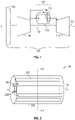
- FIG. 1 illustrates one embodiment of a combination of a combustion system with an integrated fuel cell (i.e., a fuel cell and combustor assembly 100) used in a gas turbine engine 102.
- the gas turbine engine 102 includes a shaft 115 that mechanically connects at least one compressor 104 to a turbine 112.
- the at least one compressor 104 receives inlet air and compresses this air via one or more stages of rotating blades. The compressed air is directed into the fuel cell and combustor assembly 100.
- the assembly 100 includes an annular combustor 106 that is circumferentially surrounded along some or all of the length of the combustor 106 by a fuel cell stack 108.
- the fuel cell stack 108 includes multiple fuel cells arranged to convert fuel and compressed air from the compressor 104 into electrical energy.
- the fuel cell stack 108 can be integrated into the outer portion of the combustor 106 such that the fuel cell stack 108 is part of the combustor 106 and is located radially outside of the combustor 106 (e.g., relative to an annular axis 110 of the combustor 106).
- the gas turbine engine 102 includes a center axis 116 within the shaft 115 that may be coincident with the annular axis 110 or may not be coincident with the annular axis 110.
- Some of the compressed air exiting the compressor 104 is directed through the fuel cells in the fuel cell stack 108 in radially inward directions toward the annular axis 110 of the combustor 106. Some or all of the remaining amount of compressed air from the compressor 104 is directed into the combustor 106 in a direction or directions along or parallel to the annular axis 110 of the combustor 106.
- the fuel cells in the fuel cell stack 108 receive fuel from fuel manifolds and air from the compressor 104, and convert this fuel and air into electrical energy. Partially oxidized fuel and air exhaust from the fuel cells in the fuel cell stack 108 flow radially inwardly into the combustor 106 toward the annular axis 110. The partially consumed fuel and air exhaust from the fuel cells, additional air from the compressor 104, and/or additional fuel from one or more fuel injectors (e.g., pilot and/or main injectors) are combusted within the combustor 106.
- fuel injectors e.g., pilot and/or main injectors
- the shaft 115 is a single shaft that connects the load or fan 114 to the compressor 104 and the turbine 112.
- the shaft 115 comprises (i) an outer shaft that connects the compressor 104 to the turbine 112, and (ii) an inner shaft that connects the load or fan 114 to the turbine 112.
- FIG. 2 schematically illustrates one embodiment of the combination of a combustion system with an integrated fuel cell (i.e., the fuel cell and combustor assembly 100 shown in FIG. 1 ).
- the assembly 100 includes the fuel cell stack 108 located radially outward of the combustor 106 relative to the annular axis 110 of the combustor 106.
- the fuel cell stack 108 includes several fuel manifolds 200 located at different portions along the perimeter of the combustor 106.
- the number and/or arrangement of the fuel manifolds 200 shown in FIG. 2 is one embodiment and is not limiting of all embodiments described herein.
- the fuel manifolds 200 are conduits that receive fuel for the fuel cells in the stack 108 and distribute the fuel to the cells.
- the fuel manifolds 200 can be fluidly coupled with a source of the fuel, such as one or more tanks or other containers of the fuel.
- the fuel manifolds 200 can include orifices that deliver the fuel to the fuel cells in locations that deliver fuel into fuel flow passages.
- the fuel is not simply injected from the fuel manifolds 200 through orifices into the air stream through the combustor 106. Instead, the fuel can be directed into flow passages as described in, for example, US 2019/0136761 A1, which is incorporated by reference herein in its entirety. As further shown in FIG.
- the fuel manifolds 200 can be elongated conduits that are elongated along directions that are parallel to or otherwise along the annular axis 110 of the combustor 106.
- the fuel manifolds 200 can have another shape, such as rings that encircle the combustor 106.
- the fuel manifolds 200 can be individually controlled.
- a controller e.g., hardware circuitry that includes and/or is coupled with one or more processors, such as microprocessors
- the amount of current that is drawn from the fuel cell stack 108 can be controlled (e.g., by the controller) during operation of an engine that includes the assembly 100.
- the controller can close or open valves to decrease or to increase (respectively) the amount of fuel flowing into the fuel cell stack 108.
- the amount of fuel flowing into the fuel cell stack 108 can be decreased to decrease the electrical current generated by the fuel cell stack 108, or can be increased to increase the current generated by the fuel cell stack 108.
- no fuel can be delivered to the fuel cell stack 108 via the fuel manifolds 200 to prevent the fuel cell stack 108 from generating any electrical current.
- the fuel cell stack 108 directly abuts the combustor 106 along the length of the combustor 106.
- the fuel cell stack 108 can form the outer surface or boundary of the combustor 106. This can include the fuel cell stack 108 being integrally formed with the combustor 106. This arrangement reduces or eliminates the need to include additional ducting to fluidly couple the fuel cell stack 108 with the combustor 106.
- the combustor 106 receives unspent fuel and air from the fuel cell stack 108 along radially inward directions oriented toward the annular axis 110 of the combustor 106.
- the combustor 106 also can receive supplemental fuel and air from the compressor 104.
- the combustor 106 further includes an interior portion 202 that is coupled with the compressor 104 and/or the turbine 112, via, e.g., a shaft (see, e.g., shaft 115 of FIG. 1 ).
- FIG. 3 illustrates a cross-sectional view of one embodiment of a combination of the combustion system with an integrated fuel cell (i.e., the fuel cell and combustor assembly 100 of FIG. 1 ) along line 3-3 shown in FIG. 2 .
- the fuel cell stack 108 circumferentially extends around the combustor 106 by completely encircling the combustor 106 around the annular axis 110.
- the fuel cell stack 108 includes several fuel cells 300 that generate electrical current. These fuel cells 300 are solid oxide fuel cells in one embodiment. Alternatively, the fuel cells 300 can be another type of fuel cell.
- the fuel cells 300 are formed as parts or segments of an annulus that encircles the combustor 106.
- the fuel cells 300 that are visible in FIG. 3 may be a single ring or an annulus of fuel cells 300 that encircles the combustor 106, with many more fuel cells 300 axially stacked together to form the fuel cell stack 108.
- multiple additional rings of fuel cells 300 may be placed on top of each other to form the fuel cell stack 108 that is elongated along the annular axis 110. While eight fuel cells 300 are shown in the ring in FIG. 3 , more or fewer fuel cells 300 can form the ring that encircles the combustor 106.
- the fuel cells 300 in the stack 108 are positioned to receive discharged air 302 from the compressor 104 (and/or a pre-burner system as described further below) and fuel 304 from the fuel manifolds 200 (and/or a catalytic partial oxidation convertor as described further below).
- the fuel cells 300 generate electrical current using this air 302 and at least some of this fuel 304, and radially direct partially oxidized fuel 306 and unused air 308 into the combustor 106 toward the annular axis 110.
- the combustor 106 combusts the partially oxidized fuel 306 and air 308 into one or more gaseous combustion products (e.g., exhaust), that are directed into and drive the downstream turbine 112.
- FIG. 4 illustrates a perspective view of another embodiment of a combination of a combustion system with an integrated fuel cell (i.e., a fuel cell and combustor system 400) that can be used in a gas turbine engine system (e.g., gas turbine engine 102 of FIG. 1 ), which is further described in, e.g., US 2020/0194799 A1, which is incorporated by reference herein in its entirety.
- the system 400 includes a housing 410 having a combustion outlet side 412 and a side 416 that is opposite to the combustion outlet side 412, a fuel and air inlet side 422 and a side 424 that is opposite to the fuel and air inlet side 422, and sides 414, 415.
- the sides 414 and 416 are not visible in the perspective view of FIG. 4 .
- the shape of the housing 410 may differ from what is shown in FIG. 4 .
- the housing 410 need not have a rectangular or a cubic shape, in another embodiment.
- the combustion outlet side 412 includes several combustion outlets 480 from which combustion gas(es) 488 is directed out of the housing 410.
- the combustion gas 488 can be created using fuel and air that is not consumed by fuel cells in a fuel cell stack inside the housing 410. This combustion gas 488 can be used to generate propulsion or thrust for a vehicle, such as a manned or an unmanned aircraft.
- the fuel and air inlet side 422 includes one or more fuel inlets 450 and one or more air inlets 460.
- one or more of the inlets 450, 460 can be on another side of the housing 410.
- the fuel inlet 450 is fluidly coupled with a source of fuel for the fuel cells, such as one or more pressurized containers of a hydrogen-containing gas and/or a catalytic partial oxidation convertor as described further below.
- a source of fuel for the fuel cells, such as one or more pressurized containers of a hydrogen-containing gas and/or a catalytic partial oxidation convertor as described further below.
- another type or source of fuel may be used.
- the air inlet 460 is fluidly coupled with a source of air for the fuel cells, such as air that is discharged from a compressor provided with a gas turbine engine (see, e.g., air 302 coming from the compressor 104 in the gas turbine engine 102 of the embodiment of FIGS. 1 to 3 ) and/or a pre-burner system as described further below.
- a source of air for the fuel cells such as air that is discharged from a compressor provided with a gas turbine engine (see, e.g., air 302 coming from the compressor 104 in the gas turbine engine 102 of the embodiment of FIGS. 1 to 3 ) and/or a pre-burner system as described further below.
- another source of air may be provided, such as, e.g., one or more pressurized containers of oxygen gas.
- the inlets 450, 460 separately receive the fuel and air from the external sources of fuel and air, and separately direct the fuel and air into the fuel cells.
- the fuel and air inlet side 422 and the combustion outlet side 412 may be the only sides of the housing 410 that are not sealed.
- the housing 410 may be sealed to prevent ingress or egress of fluids (gas and/or liquid) into and out of the housing 410, but for the inlets 450, 460 and the combustion outlets 480.
- the air and fuel that are directed into the housing 410 via the inlets 450, 460 may be entirely or substantially consumed (e.g., at least 98% of the volume or mass is consumed) by the fuel cells inside the housing 410 and/or the generation of combustion gas 488.
- partially oxidized fuel and unused air from the fuel cells inside the housing 410 can be directed into a combustor, such that the combustor combusts the partially oxidized fuel and air into one or more gaseous combustion products (e.g., exhaust), that are directed into and drive a downstream turbine (see, e.g., combustor 106 and turbine 112 of the gas turbine engine 102 of the embodiment of FIGS. 1 to 3 ).
- gaseous combustion products e.g., exhaust
- the system 400 can be formed from one hundred fuel cells stacked side-by-side from the end or fuel and air inlet side 422 to the opposite side 424.
- the system 400 can include fewer or more fuel cells stacked side-by-side.
- the system 400 can be eight centimeters tall, 2.5 centimeters wide, and twenty-four centimeters long.
- the system 400 can be taller or shorter, wider or narrower, and/or longer or shorter than these example dimensions.
- the combination of the combustion system with an integrated fuel cell can be integrated into the liner of a combustor such that the combustor is circumferentially surrounded along some or all the length of the combustor by the housing 410 having a fuel cell stack or plurality of fuel cells.
- the system 400 or housing 410 directly abuts the combustor of, e.g., a gas turbine engine along the length of the combustor (see, e.g., combustor 106 of the gas turbine engine 102 of the embodiment of FIG. 1 ).
- the housing 410 can form the outer surface or boundary of the combustor.
- the housing 410 being integrally formed with the combustor. This arrangement reduces or eliminates the need to include additional ducting to fluidly couple the housing 410 with the combustor.
- the fuel cell stack can be axially coupled to the combustor, meaning the fuel cell stack is upstream of the combustor but not necessarily circumferentially surrounding the combustor.
- the combustor is fluidly coupled with the housing 410 (see, e.g., combustor 106 of the gas turbine engine 102 of the embodiment of FIGS. 1 to 3 ).
- the combustor receives unspent fuel and air (e.g., combustion gas 488) from the housing 410 along radially inward directions oriented toward an annular axis of the combustor (see, e.g., annular axis 110 of the combustor 106 of the embodiment of FIGS. 1 to 3 ).
- fuel cells within the housing 410 are positioned to receive (i) discharged air from a compressor and/or a pre-burner system as described further below and (ii) fuel from a source, such as, e.g., a catalytic partial oxidation convertor as described further below.
- the fuel cells within the housing 410 generate electrical current using this air and at least some of this fuel, and radially direct partially oxidized fuel and unused air into the combustor.
- the combustor combusts the partially oxidized fuel and air into one or more gaseous combustion products (e.g., exhaust), that can be directed into and drive a downstream turbine (see, e.g., combustor 106 and turbine 112 of the gas turbine engine 102 of the embodiment of FIGS. 1 to 3 ).
- gaseous combustion products e.g., exhaust
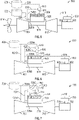
- FIG. 5 illustrates an engine assembly, and more particularly, a gas turbine engine 500 having a combination of a combustion system with an integrated fuel cell according to one embodiment of the present disclosure.
- the gas turbine engine 500 includes a shaft 515 that mechanically connects at least one compressor 504 to a turbine 512.
- the gas turbine engine 500 further includes a combustor 506 (e.g., a gas turbine combustor), and a fuel cell 508 (or fuel cell stack) having a plurality of fuel cells (e.g., SOFCs) integrated with the combustor 506.
- the fuel cell 508 e.g., solid oxide fuel cell
- the fuel cell 508 is integrated into the outer and/or inner liners of the combustor 506.
- the fuel cell 508 could be integrated into the combustor 506 according to the embodiment illustrated in FIGS. 1 to 3 .
- the fuel cell 508 could comprise the system 400 with housing 410 illustrated in FIG. 4 , which is then integrated into the outer and/or inner liners of the combustor 506.
- the fuel cell 508 can also be integrated into the outer and/or inner liners of the combustor 506 in another manner.
- the exhaust stream from the fuel cell stack can be manifolded directly into the outer and/or inner liners of the combustor 506.
- part of the fuel cell stack and the combustor liners can be integrated via an additively manufacturing method (e.g., 3-D printing).
- the gas turbine engine 500 also includes a catalytic partial oxidation (C-POX) convertor 510 for developing a hydrogen rich fuel stream (e.g., optimizing a hydrogen content of a fuel stream) (see, e.g., fuel stream 511) for fuel cell 508 (e.g., solid oxide fuel cell) that is integrated into the outer and/or inner liners of the combustor 506.
- C-POX catalytic partial oxidation
- the gas turbine engine 500 further includes a fuel source 520 (e.g., a hydrocarbon fuel source, including, e.g., a carbon-neutral fuel or synthetic hydrocarbons) for directing a fuel stream 525 into the catalytic partial oxidation (C-POX) convertor 510 for developing a hydrogen rich fuel stream 511.
- a fuel source 520 e.g., a hydrocarbon fuel source, including, e.g., a carbon-neutral fuel or synthetic hydrocarbons
- C-POX catalytic partial oxidation
- the hydrogen rich fuel stream 511 is then directed into the fuel cell 508 located in a liner region of the combustor 506.
- the fuel source 520 could be a hydrogen (H 2 ) fuel source, as opposed to a hydrocarbon fuel source.
- the catalytic partial oxidation (C-POX) convertor 510 may not be necessary for this hydrogen (H 2 ) fuel source, and, thus, the hydrogen (H 2 ) fuel stream (e.g., fuel stream 525) can be sent directly into the fuel cell 508 (e.g., SOFC) that is integrated into the outer and/or inner liners of the combustor 506.
- the fuel cell 508 e.g., SOFC
- the gas turbine engine 500 of FIG. 5 also includes a secondary fuel source 522 (e.g., a hydrocarbon fuel source, including, e.g., a carbon-neutral fuel or synthetic hydrocarbons, such as, e.g., synthetic fuel (i.e., synfuel), which is made from coal, corn, etc., as a substitute for a petroleum product).
- a secondary fuel source 522 e.g., a hydrocarbon fuel source, including, e.g., a carbon-neutral fuel or synthetic hydrocarbons, such as, e.g., synthetic fuel (i.e., synfuel), which is made from coal, corn, etc., as a substitute for a petroleum product.
- a fuel stream 526 from this secondary fuel source 522 can be directed into the combustor 506 through a main/pilot fuel nozzle (not shown) and/or to aid in developing a combustion product within the combustor 506.
- the combustor 506 includes one or more main/pilot fuel nozzles and/or injectors (not shown) with a mixer and/or swirler that can aid in at least partially mixing air and fuel to facilitate combustion of fuel and air, the main/pilot flames being configured to combust the fuel directed into the combustor from the fuel cell stack into the one or more gaseous combustion products.
- the compressor 504 of the gas turbine engine 500 receives inlet air (not shown) and compresses this air via one or more stages of rotating blades.
- the compressed air 528 is then directed into the catalytic partial oxidation (C-POX) convertor 510 for developing a hydrogen rich fuel stream (e.g., optimizing a hydrogen content of a fuel stream) (see, e.g., fuel stream 511) for the fuel cell 508 (e.g., solid oxide fuel cell) that is integrated into the outer and/or inner liners of the combustor 506.
- a hydrogen rich fuel stream e.g., optimizing a hydrogen content of a fuel stream
- the fuel cell 508 e.g., solid oxide fuel cell
- Portions of the compressed air 528, i.e., portion 528A and portion 528B are also directed into the fuel cell 508 and the combustor 506, respectively, to facilitate the functioning of the fuel cell 508 and the combustor 506.
- the fuel cell 508 that is integrated into the outer and/or inner liners of the combustor 506 converts the fuel stream 511 and compressed air 528A sent into the fuel cell 508 into electrical energy 518 (e.g., DC current).
- This electrical energy or DC current 518 is directed into an AC/DC convertor 530 in order to change the DC current 518 into AC current 535 that can be effectively utilized by one or more subsystems 550, such as, e.g., a generator, a fan, or other electrical machine.
- partially oxidized fuel and air exhaust from the fuel cell 508 flow radially inward into the combustor 506.
- the partially consumed fuel and air exhaust from the fuel cell 508, additional air (e.g., compressed air 528B) from the compressor 504, and/or additional fuel from one or more fuel injectors (e.g., fuel stream 526 from secondary fuel source 522) are combusted within the combustor 506. Exhaust from the combusted fuel and air mixture is then directed into the turbine 512, which converts the exhaust into energy via the rotating shaft 515 that can be used to power one or more loads 514, such as a fan used to propel a vehicle (e.g., an aircraft), a generator, or the like.
- the shaft 515 is a single shaft that connects the fan 514 to the compressor 504 and the turbine 512.
- the shaft 515 comprises (i) an outer shaft that connects the compressor 504 to the turbine 512, and (ii) an inner shaft that connects the fan 514 to the turbine 512.
- FIG. 5 illustrates a fan 514 being mechanically connected to the turbine 512 via the shaft 515, this fan 514 could be alternatively omitted from the gas turbine engine 500 (see, e.g., gas turbine engine 600/700 of FIGS. 6 and 7 , respectively).
- FIG. 6 illustrates an engine assembly, and more particularly, a gas turbine engine 600 having a combination of a combustion system with an integrated fuel cell according to another embodiment of the present disclosure.
- the gas turbine engine 600 includes a shaft 615 that mechanically connects at least one compressor 604 to a turbine 612.
- the gas turbine engine 600 further includes a combustor 606 (e.g., a gas turbine combustor), and a fuel cell 608 (or fuel cell stack) having a plurality of fuel cells (e.g., SOFCs) integrated with the combustor 606.
- the fuel cell 608 e.g., solid oxide fuel cell
- the fuel cell 608 is integrated into the outer and/or inner liners of the combustor 606.
- the fuel cell 608 could be integrated into the combustor 606 according to the embodiment illustrated in FIGS. 1 to 3 .
- the fuel cell 608 could comprise the system 400 with housing 410 illustrated in FIG. 4 , which is then integrated into the outer and/or inner liners of the combustor 606.
- the fuel cell 608 can also be integrated into the outer and/or inner liners of the combustor 606 in another manner.
- the gas turbine engine 600 also includes a catalytic partial oxidation (C-POX) convertor 610 for developing a hydrogen rich fuel stream (e.g., optimizing a hydrogen content of a fuel stream) (see, e.g., fuel stream 611) for fuel cell 608 (e.g., solid oxide fuel cell) that is integrated into the outer and/or inner liners of the combustor 606.
- C-POX catalytic partial oxidation
- the gas turbine engine 600 further includes a fuel source 620 (e.g., a hydrocarbon fuel source, including, e.g., a carbon-neutral fuel or synthetic hydrocarbons) for directing a fuel stream 625A into the catalytic partial oxidation (C-POX) convertor 610 for developing a hydrogen rich fuel stream 611.
- a fuel source 620 e.g., a hydrocarbon fuel source, including, e.g., a carbon-neutral fuel or synthetic hydrocarbons
- C-POX catalytic partial oxidation
- the hydrogen rich fuel stream 611 is then directed into the fuel cell 608 located in a liner region of the combustor 606.
- the fuel source 620 could be a hydrogen (H 2 ) fuel source, as opposed to a hydrocarbon fuel source.
- the catalytic partial oxidation (C-POX) convertor 610 may not be necessary for this hydrogen (H 2 ) fuel source, and, thus, the hydrogen (H 2 ) fuel stream (e.g., fuel stream 625A) can sent directly into the fuel cell 608 (e.g., SOFC) that is designed/integrated into the outer and/or inner liners of the combustor 606.
- the fuel cell 608 e.g., SOFC
- the gas turbine engine 600 of the embodiment of FIG. 6 does not include a secondary fuel source (e.g., secondary fuel source 522 of the embodiment of FIG. 5 ).
- a secondary fuel stream 625B is directed into the combustor 606 from the fuel source 620 to run a main/pilot flame (not shown) within the combustor 606 and/or to aid in developing a combustion product within the combustor 606.
- the compressor 604 of the gas turbine engine 600 receives inlet air (not shown) and compresses this air via one or more stages of rotating blades.
- the compressed air 628 is then directed into the catalytic partial oxidation (C-POX) convertor 610 for developing a hydrogen rich fuel stream (e.g., optimizing a hydrogen content of a fuel stream) (see, e.g., fuel stream 611) for the fuel cell 608 (e.g., solid oxide fuel cell) that is designed into the outer and/or inner liners of the combustor 606.
- Portions of the compressed air 628, i.e., portion 628A and portion 628B are also directed into the fuel cell 608 and the combustor 606, respectively, to facilitate the functioning of the fuel cell 608 and the combustor 606.
- the fuel cell 608 that is integrated into the outer and/or inner liners of the combustor 606 converts the fuel 611 and compressed air 628A sent into the fuel cell 608 into electrical energy 618 (e.g., DC current).
- This electrical energy or DC current 618 is directed into an AC/DC convertor 630 in order to change the DC current 618 into AC current 635 that can be effectively utilized by one or more subsystems 650, such as, e.g., a generator, fan, or other electrical machine.
- partially oxidized fuel and air exhaust from the fuel cell 608 flow radially inward into the combustor 606.
- the partially consumed fuel and air exhaust from the fuel cell 608, additional air (e.g., compressed air 628B) from the compressor 604, and/or additional fuel from one or more fuel injectors (e.g., fuel stream 625B from fuel source 620) are combusted within the combustor 606. Exhaust from the combusted fuel and air mixture is then directed into the turbine 612, which converts the exhaust into energy via the rotating shaft 615 that can be used to power one or more loads (not shown).
- a heat exchanger 680 can optionally be included between the catalytic partial oxidation (C-POX) convertor 610 and the fuel cell 608 located in a liner region of the combustor 606.
- the heat exchanger is configured to condition air and/or fuel (i.e., fuel stream 611) going into the fuel cell 608 from the catalytic partial oxidation (C-POX) convertor 610.
- another portion of the compressed air 628 from the compressor 604, i.e., portion 628C is directed into the heat exchanger 680 to control the air temperature.
- this heated air 628C may be directed into (not shown) and utilized within the fuel cell 608 or directed (not shown) into the combustor 606 and combusted within the combustor 606 with the fuel 625B directed into the combustor 606.
- the flow rates of the portions of discharged air 628A, 628B and 628C being discharged from the compressor 604 can be controlled to control the temperature of fuel stream 611 exiting the heat exchanger 680 into the fuel cell 608.
- the air flow 628C can be increased to absorb more heat and then directed to the fuel cell 608 and/or the combustor 606, in which case the air flow 628A directed to the fuel cell 608 and/or the air flow 628B directed to the combustor can be decreased accordingly.
- FIG. 7 illustrates an engine assembly, and more particularly, a gas turbine engine 700 having a combination of a combustion system with an integrated fuel cell according to another embodiment of the present disclosure.
- the gas turbine engine 700 includes a shaft 715 that mechanically connects at least one compressor 704 to a turbine 712.
- the gas turbine engine 700 further includes a combustor 706 (e.g., a gas turbine combustor), and a fuel cell 708 (or fuel cell stack) having a plurality of fuel cells (e.g., SOFCs) integrated with the combustor 706.
- the fuel cell 708 e.g., solid oxide fuel cell
- the fuel cell 708 is designed into the outer and/or inner liners of the combustor 706.
- the fuel cell 708 could be integrated into the combustor 706 according to the embodiment illustrated in FIGS. 1 to 3 .
- the fuel cell 708 could comprise the system 400 with housing 410 illustrated in FIG. 4 , which is then integrated into the outer and/or inner liners of the combustor 706.
- the fuel cell 708 can also be integrated into the outer and/or inner liners of the combustor 706 in another manner.
- the gas turbine engine 700 also includes a catalytic partial oxidation (C-POX) convertor 710 for developing a hydrogen rich fuel stream (e.g., optimizing a hydrogen content of a fuel stream) (see, e.g., fuel stream 711) for fuel cell 708 (e.g., solid oxide fuel cell) that is designed into the outer and/or inner liners of the combustor 706.
- C-POX catalytic partial oxidation
- the gas turbine engine 700 further includes a pre-burner system 760, for raising the temperature of air 728 that is discharged from the compressor 704 to a temperature high enough to enable fuel cell temperature control (e.g., ⁇ 600°C to 800°C).
- the pre-burner system 760 and the catalytic partial oxidation (C-POX) convertor 710 are manifolded together to provide conditioned air and fuel to the fuel cell 708.
- the catalytic partial oxidation (C-POX) convertor 710, the pre-burner system 760, and the fuel cell 708 and/or fuel cell stack having a plurality of fuel cells are closely coupled within the gas turbine engine 700 (or engine assembly), such that the catalytic partial oxidation (C-POX) convertor 710, the pre-burner system 760, and the fuel cell 708 and/or fuel cell stack are positioned as close as possible to each other within the gas turbine engine 700 (or engine assembly).
- the gas turbine engine 700 further includes a fuel source 720 (e.g., a hydrocarbon fuel source, including, e.g., a carbon-neutral fuel or synthetic hydrocarbons) for directing a fuel stream 725A into the catalytic partial oxidation (C-POX) convertor 710 and the pre-burner system 760.
- a fuel source 720 e.g., a hydrocarbon fuel source, including, e.g., a carbon-neutral fuel or synthetic hydrocarbons
- C-POX catalytic partial oxidation
- a first portion of fuel 725C from the fuel stream 725A of fuel source 720 is directed to the pre-burner system 760, while a second portion of fuel 725D from the fuel stream 725A of fuel source 720 is directed to the catalytic partial oxidation (C-POX) convertor 710 for developing a hydrogen rich fuel stream (e.g., optimizing a hydrogen content of a fuel stream) (e.g., fuel stream 711).
- C-POX catalytic partial oxidation
- this heated air 765 is then directed into the fuel cell 708 to facilitate the functioning of the fuel cell 708 (e.g., SOFC) located in a liner region of the combustor 706.
- the portion of fuel 725D that is directed from the fuel stream 725A of fuel source 720 into the catalytic partial oxidation (C-POX) convertor 710 is developed into a hydrogen rich fuel stream 711 that is also fed into the fuel cell 708.
- the fuel source 720 could be a hydrogen (H 2 ) fuel source, as opposed to a hydrocarbon fuel source.
- the catalytic partial oxidation (C-POX) convertor 710 may not be necessary for this hydrogen (H 2 ) fuel source, and, thus, the hydrogen (H 2 ) fuel stream (e.g., fuel stream 725D) can sent directly into the fuel cell 708 (e.g., SOFC) that is integrated into the outer and/or inner liners of the combustor 706.
- the fuel cell 708 e.g., SOFC
- the pre-burner system 760 of FIG. 7 could alternatively be a heat exchanger or another device for raising the temperature of the air 728 that is discharged from the compressor 704 to a temperature high enough to enable fuel cell temperature control (e.g., ⁇ 600°C to 800°C).
- the engine 700 of the embodiment of FIG. 7 does not include a secondary fuel source (e.g., secondary fuel source 522 of the embodiment of FIG. 5 ).
- a secondary fuel stream 725B is directed into the combustor 706 from the fuel source 720 to run a main/pilot flame (not shown) within the combustor 706 and/or to aid in developing a combustion product within the combustor 706.
- the compressor 704 of the gas turbine engine 700 receives inlet air (not shown) and compresses this air via one or more stages of rotating blades.
- the compressed air 728 is then directed into (i) the pre-burner system 760, as discussed above, for raising the temperature of air 765 that is directed into the fuel cell 708, and (ii) the catalytic partial oxidation (C-POX) convertor 710 for developing a hydrogen rich fuel stream (e.g., optimizing a hydrogen content of a fuel stream) (see, e.g., fuel stream 711) for the fuel cell 708 (e.g., solid oxide fuel cell) that is designed into the outer and/or inner liners of the combustor 706.
- a portion of the compressed air 728, i.e., portion 728A, is also directed into the combustor 706 to facilitate the functioning of the combustor 706.
- the fuel cell 708 that is integrated into the outer and/or inner liners of the combustor 706 converts the fuel 711 and air 765 sent into the fuel cell 708 into electrical energy 718 (e.g., DC current).
- This electrical energy or DC current 718 is directed into an AC/DC convertor 730 in order to change the DC current 718 into AC current 735 that can be effectively utilized by one or more subsystems 750, such as, e.g., a generator, fan, or other electrical machine.
- partially oxidized fuel and air exhaust from the fuel cell 708 flow radially inward into the combustor 706.
- the partially consumed fuel and air exhaust from the fuel cell 708, additional air (e.g., compressed air 728A) from the compressor 704, and/or additional fuel from one or more fuel injectors (e.g., fuel stream 725B from fuel source 720) are combusted within the combustor 706. Exhaust from the combusted fuel and air mixture is then directed into the turbine 712, which converts the exhaust into energy via the rotating shaft 715 that can be used to power one or more loads (not shown).
- both air and fuel can be directed to the fuel cell (508, 608, 708) (SOFC) in a single pass, meaning there is no recycling of the unburned fuel or air from the fuel cell exhaust to the inlet of the fuel cell (508, 608, 708).
- SOFC fuel cell
- the inlet air for the fuel cell (508, 608, 708) comes solely from the upstream engine compressor (504, 604, 704) without any other separately controlled air source
- the inlet air for the fuel cell (508, 608, 708) that is discharged from the compressor (504, 604, 704) is subject to the air temperature changes that occur at different flight stages.
- the air within the aircraft engine compressor may work at 200°C during idle, 600°C during take-off, 450°C during cruise, etc.
- the pre-burner system 760 by fluidly connecting a pre-burner system 760 to (i) the engine compressor 704 (at an upstream side to the pre-burner system 760) and (ii) the fuel cell 708 (e.g., SOFC) (at a downstream side to the pre-burner system 760), the pre-burner system 760 serves as a control device or system to maintain the air 765 being directed into the fuel cell 708 at a temperature at a desired range (e.g., 700°C ⁇ 200°C). Furthermore, by integrating the pre-burner system 760 with the catalytic partial oxidation (C-POX) convertor 710, a better thermal management with faster startup could be achieved. This further improves the system operability.
- C-POX catalytic partial oxidation
- the diversion of fuel (e.g., fuel portions 725A, 725B, 725C and/or 725D) from the fuel source 720 can be individually controlled to better manage the temperature of the air 765 being directed into the fuel cell 708.
- a controller e.g., hardware circuitry that includes and/or is coupled with one or more processors, such as microprocessors
- processors such as microprocessors
- the temperature of the air 728 that is discharged from the compressor 704 can be controlled by controlling the flow of fuel to the pre-burner system 760 via the controller.
- the controller can close or open valves to decrease or to increase (respectively) the amount of fuel flowing into the pre-burner system 760.
- the amount of fuel flowing into the pre-burner system 760 can be decreased to thereby decrease the temperature of the air 728 that is discharged from the compressor 704 and directed into the pre-burner system 760, or can be increased to thereby increase the temperature of the air 728 that is discharged from the compressor 704 and directed into the pre-burner system 760.
- no fuel can be delivered to the pre-burner system 760 via the fuel source 720 to prevent the pre-burner system 760 from increasing and/or decreasing the temperature of the air 728 that is discharged from the compressor 704 and directed into the pre-burner system 760.
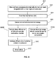
- FIG. 8 illustrates a flowchart of one embodiment of a method 800 of operating an integrated fuel cell and a combustor assembly.
- the method 800 can describe the operations performed in generating thrust and electrical current using the integrated fuel cell and combustor assemblies described herein (see, e.g., FIGS. 1 and 4 to 7 ).
- air that is discharged from a compressor of an engine is directed into fuel cells of a fuel cell stack of the integrated fuel cell and combustor assembly.
- this air can be preheated by a pre-burner system (see, e.g., pre-burner system 760 of FIG. 7 ) prior to being directed into the fuel cells.
- this air can be preheated by a heat exchanger (see, e.g., heat exchanger 680 of FIG. 6 ) using heat generated from a catalytic partial oxidation (C-POX) convertor (see, e.g., catalytic partial oxidation (C-POX) convertor 610 of FIG. 6 ).
- C-POX catalytic partial oxidation
- step 804 fuel is directed into the fuel cells of the integrated fuel cell and combustor assembly via a fuel source and/or a catalytic partial oxidation convertor.
- the direction of fuel into the fuel cells (at step 804) and the flow of air into the fuel cells (at step 802) can occur simultaneously, concurrently, sequentially, or in a reverse order than as shown in FIG. 8 .
- the air and fuel in the fuel cells are at least partially converted into electrical energy.
- the fuel cells can be connected in a series to build up a direct current that is created in the fuel cells.
- this electrical energy or DC current is converted into AC current to be used to power one or more engine subsystems, such as a fan of the engine, a generator, another load, or used to charge a battery.
- effluent of the fuel cells is radially directed inward into the combustor.
- the effluent can include unused air, unburned fuel, and/or other gaseous constituents of the fuel cells.
- the effluent is combusted (at least partially) in the combustor.
- Additional air from the compressor and/or fuel from fuel injectors can be directed into the combustor to aid with the combustion.
- the combustion in the combustor generates gaseous combustion products.
- a turbine of the engine is driven by the gaseous combustion products in the combustor.
- exhaust from the combustor may be directed into the turbine to rotate the turbine via, e.g., a shaft.
- an engine system that combines a fuel cell (e.g., SOFC) and a catalytic partial oxidation (C-POX) convertor/reformer as a pre-combustor on an engine system, such as, e.g., a jet engine system, for power generation and propulsion for aviation platforms.
- a fuel cell e.g., SOFC
- C-POX catalytic partial oxidation
- an engine system can operate on carbon neutral fuels (e.g., CNLF ethanol and/or CNLF synfuel) and can achieve high cruise efficiency at reduced emissions.
- carbon neutral fuels e.g., CNLF ethanol and/or CNLF synfuel
- the integration of a fuel cell and a catalytic partial oxidation (C-POX) convertor/reformer as a pre-combustor to a gas turbine generator set can produce power.
- a gas turbine generator set i.e., genset
- shaft (or mechanical) power can be converted into AC electric power and subsequently into DC power.
- some of the shaft (or mechanical) power can be used for propulsion, if, for example, a fan is connected to the shaft.
- AC power can be supplied instead of DC power.
- a combined system having a fuel cell and a catalytic partial oxidation (C-POX) convertor/reformer as a pre-combustor on an engine system is anticipated to have a very high cruise efficiency and fuel flexibility from various fuels, including carbon neutral liquid fuels (CNLF).
- C-POX catalytic partial oxidation
- a combined system having a fuel cell and a catalytic partial oxidation (C-POX) convertor/reformer as a pre-combustor on an engine system is anticipated to deliver DC power at over 60% cruise efficiency, while being able to operate on carbon neutral liquid fuels (CNLF), such as, e.g., ethanol, synfuel and others.
- CNLF carbon neutral liquid fuels
- a combined system is developed that minimizes the total number of components, while also being compact, and still having high power density.
- the integration of a fuel cell e.g., SOFC
- a fuel cell e.g., SOFC
- fuel heat release can be balanced between the fuel cell and the combustor.
- unburned products from the fuel cell e.g., approximately 50% to 85%
- a catalytic partial oxidation (C-POX) convertor provides pre-heating of air and fuel and can be combined with a heat-exchanger.
- the catalytic partial oxidation (C-POX) convertor can send heat to a turbine.
- a compressor e.g., a genset compressor
- a compressor can supply high pressure air leveraging all synergies provided by the system.
- a heat exchanger conditions air and fuel going into a combustor having an integrated fuel cell (SOFC), which uses waste heat from a catalytic partial oxidation (C-POX) convertor included with the engine system.
- SOFC integrated fuel cell
- C-POX catalytic partial oxidation
- a high efficiency propulsion system that delivers fuel savings.
- an engine system that has the ability to operate on carbon neutral liquid fuels (CNLF), which effectively has zero or low greenhouse gas emissions.
- CNLF carbon neutral liquid fuels
- a fuel cell e.g., SOFC
- SOFC SOFC
- a combined system having a fuel cell and a catalytic partial oxidation (C-POX) convertor/reformer as a pre-combustor on an engine system provides more than 10 ⁇ to 20x kW/kg specific power density improvement over a metal supported fuel cell (MS-SOFC).
- C-POX catalytic partial oxidation
- a combined system having a fuel cell and a catalytic partial oxidation (C-POX) convertor/reformer as a pre-combustor on an engine system provides up to 75% (e.g., around 60% to 75%) electrochemical voltage efficiency.
- C-POX catalytic partial oxidation
- a combined system having a fuel cell and a catalytic partial oxidation (C-POX) convertor/reformer as a pre-combustor on an engine system provides a significant balance of plant savings compared to conventional SOFC-GT hybrid systems, such that otherwise unutilized fuel cell products and heat go directly into the combustor.
- C-POX catalytic partial oxidation
- a combined system having a fuel cell and a catalytic partial oxidation (C-POX) convertor/reformer as a pre-combustor on an engine system provides a fast response of the fuel cell (e.g., SOFC) for electrochemical output.
- a fuel cell e.g., SOFC
- the embedding or integrating of the fuel cell (e.g., SOFC) with the combustor eliminates the need for a separate pressure vessel and/or piping for the fuel cell.
- the fuel cell e.g., SOFC
- a combined system having a fuel cell and a catalytic partial oxidation (C-POX) convertor/reformer as a pre-combustor on an engine system is provided that can achieve high efficiency (e.g., at least 60%) with minimal changes to existing propulsion systems, while also having the ability to work on a variety of liquified jet fuels.
- the fuel cell e.g., SOFC
- hydrogen (H 2 ) fuel there is no need for a hydrogen fuel infrastructure.
- a combined system that internally integrates a fuel cell (SOFC), a catalytic partial oxidation (C-POX) convertor, and a gas turbine engine into a single arrangement with a compact design.
- SOFC fuel cell
- C-POX catalytic partial oxidation
- a combined system having a fuel cell and a catalytic partial oxidation (C-POX) convertor/reformer as a pre-combustor on an engine system thermodynamically recovers waste heat from the catalytic partial oxidation (C-POX) convertor/reformer and the fuel cell, thereby yielding nearly 100% efficient thermoelectric conversion.
- C-POX catalytic partial oxidation
- a combined system having a fuel cell and a catalytic partial oxidation (C-POX) convertor/reformer as a pre-combustor on an engine system is provided that can run on synfuel, which allows for (i) at least 58% cruise electricity production and/or (ii) at least 70% carbon dioxide (CO 2 ) emission reduction.
- C-POX catalytic partial oxidation
- An engine assembly comprising: (a) a combustor; (b) a fuel cell stack integrated with the combustor, the fuel cell stack configured (i) to direct fuel and air exhaust from the fuel cell stack into the combustor and (ii) to generate electrical energy; (c) a catalytic partial oxidation convertor that is fluidly connected to the fuel cell stack, the catalytic partial oxidation convertor being configured to optimize a hydrogen content of a fuel stream to be directed into the fuel cell stack; and (d) one or more subsystems electrically connected with the fuel cell stack, the one or more subsystems being configured to receive the electrical energy generated by the fuel cell stack, wherein the combustor is configured to combust the fuel and air exhaust from the fuel cell stack into one or more gaseous combustion products that drive a downstream turbine.
- the engine assembly of any preceding clause further comprising a compressor that is fluidly connected upstream of (i) the combustor and (ii) the catalytic partial oxidation convertor, the compressor being configured to direct a portion of air into the catalytic partial oxidation convertor.
- the engine assembly of any preceding clause further comprising a fuel source that provides fuel and is fluidly connected to the catalytic partial oxidation convertor, wherein a portion of the fuel is directed from the fuel source to the catalytic partial oxidation convertor to optimize the hydrogen content of the fuel stream directed into the fuel cell stack.
- the fuel source comprises at least one of kerosene fuels and synthetic analogues, bio-jet fuels, synthetic gasoline, biodiesel, methanol, dimethyl ether (DME), ethanol, glycerol, formic acid, ammonia, hydrazine hydrate, liquid hydrogen, compressed hydrogen, and combinations thereof.
- the fuel source comprises at least one of kerosene fuels and synthetic analogues, bio-jet fuels, synthetic gasoline, biodiesel, methanol, dimethyl ether (DME), ethanol, glycerol, formic acid, ammonia, hydrazine hydrate, liquid hydrogen, compressed hydrogen, and combinations thereof.
- the engine assembly of any preceding clause further comprising an AC/DC convertor configured to convert DC current of the electrical energy generated by the fuel cell stack into AC current to power the one or more subsystems.
- the engine assembly of any preceding clause further comprising a pre-burner system fluidly connected to the fuel cell stack, the pre-burner system being configured to control a temperature of an air flow directed into the fuel cell stack to 700°C ⁇ 200°C.
- the engine assembly of any preceding clause further comprising a fuel source that provides fuel and is fluidly connected to the pre-burner system and the catalytic partial oxidation convertor, wherein (i) a first portion of the fuel is directed from the fuel source to the pre-burner system to raise a temperature of a portion of air directed into the pre-burner system from a compressor and (ii) a second portion of the fuel is directed from the fuel source to the catalytic partial oxidation convertor for optimizing the hydrogen content of the fuel stream to be directed into the fuel cell stack.
- the combustor comprises one or more main/pilot fuel nozzles being configured to combust the fuel and air exhaust directed into the combustor from the fuel cell stack into the one or more gaseous combustion products.
- the engine assembly of any preceding clause further comprising a heat exchanger that is fluidly connected to the catalytic partial oxidation convertor and the fuel cell stack, the heat exchanger being configured to condition inlet air and/or fuel entering the fuel cell stack or the combustor.
- the fuel cell stack is at least one of (i) circumferentially surrounding the combustor and (ii) axially coupled to the combustor.
- An engine assembly comprising: (a) a combustor; (b) a fuel cell stack integrated with the combustor, the fuel cell stack configured (i) to direct fuel and air exhaust from the fuel cell stack into the combustor and (ii) to generate electrical energy; (c) a catalytic partial oxidation convertor that is fluidly connected to the fuel cell stack, the catalytic partial oxidation convertor being configured to optimize a hydrogen content of a fuel stream to be directed into the fuel cell stack; (d) an AC/DC convertor configured to convert DC current of the electrical energy generated by the fuel cell stack into AC current; and (e) one or more subsystems electrically connected with the fuel cell stack, the one or more subsystems being configured to receive the AC current, wherein the combustor is configured to combust the fuel and air exhaust from the fuel cell stack into one or more gaseous combustion products that drive a downstream turbine.
- the engine assembly of any preceding clause further comprising a compressor that is fluidly connected upstream of (i) the combustor and (ii) the catalytic partial oxidation convertor, the compressor being configured to direct a portion of air into the catalytic partial oxidation convertor.
- the engine assembly of any preceding clause further comprising a fuel source that provides fuel and is fluidly connected to the catalytic partial oxidation convertor, wherein a portion of the fuel is directed from the fuel source to the catalytic partial oxidation convertor to optimize the hydrogen content of the fuel stream directed into the fuel cell stack.
- the fuel source comprises at least one of kerosene fuels and synthetic analogues, bio-jet fuels, synthetic gasoline, biodiesel, methanol, dimethyl ether (DME), ethanol, glycerol, formic acid, ammonia, hydrazine hydrate, liquid hydrogen, compressed hydrogen, and combinations thereof.
- the fuel source comprises at least one of kerosene fuels and synthetic analogues, bio-jet fuels, synthetic gasoline, biodiesel, methanol, dimethyl ether (DME), ethanol, glycerol, formic acid, ammonia, hydrazine hydrate, liquid hydrogen, compressed hydrogen, and combinations thereof.
- the engine assembly of any preceding clause further comprising a pre-burner system fluidly connected to the fuel cell stack, the pre-burner system being configured to control a temperature of an air flow directed into the fuel cell stack to 700°C ⁇ 200°C.
- the engine assembly of any preceding clause further comprising a fuel source that provides fuel and is fluidly connected to the pre-burner system and the catalytic partial oxidation convertor, wherein (i) a first portion of the fuel is directed from the fuel source to the pre-burner system to raise a temperature of a portion of air directed into the pre-burner system from a compressor and (ii) a second portion of the fuel is directed from the fuel source to the catalytic partial oxidation convertor for optimizing the hydrogen content of the fuel stream to be directed into the fuel cell stack.
- the combustor comprises one or more main/pilot fuel nozzles being configured to combust the fuel and air exhaust directed into the combustor from the fuel cell stack into the one or more gaseous combustion products.
- the engine assembly of any preceding clause further comprising a heat exchanger that is fluidly connected to the catalytic partial oxidation convertor and the fuel cell stack, the heat exchanger being configured to condition inlet air and/or fuel entering the fuel cell stack or the combustor.
- a method comprising: (a) directing air from a compressor into fuel cells of a fuel cell stack integrated with a combustor of a turbine engine; (b) directing fuel into the fuel cells of the fuel cell stack; (c) converting at least some of the air and fuel that enters the fuel cells of the fuel cell stack into electrical energy; (d) converting the electrical energy into AC current for use by one or more engine systems; (e) radially directing fuel and air exhaust from the fuel cell stack into a combustor; (f) combusting the fuel and air exhaust into gaseous combustion products in the combustor; and (g) driving a turbine of a turbine engine using the gaseous combustion products.
Landscapes
- Engineering & Computer Science (AREA)
- Chemical & Material Sciences (AREA)
- Combustion & Propulsion (AREA)
- General Engineering & Computer Science (AREA)
- Mechanical Engineering (AREA)
- Chemical Kinetics & Catalysis (AREA)
- Life Sciences & Earth Sciences (AREA)
- Electrochemistry (AREA)
- General Chemical & Material Sciences (AREA)
- Sustainable Energy (AREA)
- Sustainable Development (AREA)
- Manufacturing & Machinery (AREA)
- Fuel Cell (AREA)
Abstract
Description
- The present subject matter generally relates to power generating systems, such as fuel cells and gas turbine engines. In particular, the present disclosure relates to a combination of a combustion system with an integrated fuel cell for a gas turbine engine. The present disclosure further relates to the inclusion of (i) a catalytic partial oxidation (C-POX) convertor for developing a hydrogen rich fuel stream and (ii) one or more subsystems powered by energy generated by the fuel cell and/or the catalytic partial oxidation (C-POX) convertor.
- Fuel efficiency of engines can be an important consideration in the selection and operation of engines. For example, fuel efficiency of gas turbine engines in aircraft can be an important (and a limiting) factor on how far the aircraft can travel. Current aircraft jet engines generally provide mostly shaft (e.g., mechanical) power that is converted into propulsion using a fan mounted shaft and a small amount of power generation. Some aircraft propulsion systems can, however, include fuel cells in addition to the gas turbine engines. These fuel cells can be located upstream of combustors or surrounding the combustors and downstream from compressors of the gas turbine engines. Compressed air that is output by the compressors flows along the length of the engine and into the fuel cells. A portion of this air is consumed by the fuel cells in generating electrical energy. The rest of the air can flow through or around the fuel cells and into a combustor. This air is then mixed with fuel and combusted in a combustor of the engine.
- An engine assembly comprising: (a) a combustor; (b) a fuel cell stack integrated with the combustor, the fuel cell stack configured (i) to direct fuel and air exhaust from the fuel cell stack into the combustor and (ii) to generate electrical energy; (c) a catalytic partial oxidation convertor that is fluidly connected to the fuel cell stack, the catalytic partial oxidation convertor being configured to optimize a hydrogen content of a fuel stream to be directed into the fuel cell stack; and (d) one or more subsystems electrically connected with the fuel cell stack, the one or more subsystems being configured to receive the electrical energy generated by the fuel cell stack, wherein the combustor is configured to combust the fuel and air exhaust from the fuel cell stack into one or more gaseous combustion products that drive a downstream turbine.
- An engine assembly comprising: (a) a combustor; (b) a fuel cell stack integrated with the combustor, the fuel cell stack configured (i) to direct fuel and air exhaust from the fuel cell stack into the combustor and (ii) to generate electrical energy; (c) a catalytic partial oxidation convertor that is fluidly connected to the fuel cell stack, the catalytic partial oxidation convertor being configured to optimize a hydrogen content of a fuel stream to be directed into the fuel cell stack; (d) an AC/DC convertor configured to convert DC current of the electrical energy generated by the fuel cell stack into AC current; and (e) one or more subsystems electrically connected with the fuel cell stack, the one or more subsystems being configured to receive the AC current, wherein the combustor is configured to combust the fuel and air exhaust from the fuel cell stack into one or more gaseous combustion products that drive a downstream turbine.
- A method comprising: (a) directing air from a compressor into fuel cells of a fuel cell stack integrated with a combustor of a turbine engine; (b) directing fuel into the fuel cells of the fuel cell stack; (c) converting at least some of the air and fuel that enters the fuel cells of the fuel cell stack into electrical energy; (d) converting the electrical energy into AC current for use by one or more engine systems; (e) radially directing fuel and air exhaust from the fuel cell stack into a combustor; (f) combusting the fuel and air exhaust into gaseous combustion products in the combustor; and (g) driving a turbine of a turbine engine using the gaseous combustion products.
- Additional features, advantages, and embodiments of the disclosure are set forth or apparent from consideration of the following detailed description, drawings, and claims. Moreover, it is to be understood that both the foregoing summary of the disclosure and the following detailed description are exemplary and intended to provide further explanation without limiting the scope of the disclosure as claimed.
- The foregoing and other features and advantages will be apparent from the following, more particular, description of various exemplary embodiments, as illustrated in the accompanying drawings, wherein like reference numbers generally indicate identical, functionally similar, and/or structurally similar elements.
-
FIG. 1 illustrates a combination of a combustion system with an integrated fuel cell used in a gas turbine engine system, according to an embodiment of the present disclosure. -
FIG. 2 illustrates the combustion system with an integrated fuel cell shown inFIG. 1 according to an embodiment of the present disclosure. -
FIG. 3 illustrates a cross-sectional view of the combustion system with an integrated fuel cell shown inFIG. 1 taken along line 3-3 inFIG. 2 according to an embodiment of the present disclosure. -
FIG. 4 illustrates a combination of a combustion system with an integrated fuel cell according to an embodiment of the present disclosure. -
FIG. 5 illustrates a gas turbine engine having a combination of a combustion system with an integrated fuel cell according to one embodiment of the present disclosure. -
FIG. 6 illustrates a gas turbine engine having a combination of a combustion system with an integrated fuel cell according to another embodiment of the present disclosure. -
FIG. 7 illustrates a gas turbine engine having a combination of a combustion system with an integrated fuel cell according to yet another embodiment of the present disclosure. -
FIG. 8 illustrates a flowchart of one embodiment of a method of operating an integrated fuel cell and a combustor assembly. - Various embodiments are discussed in detail below. While specific embodiments are discussed, this is done for illustration purposes only. A person skilled in the relevant art will recognize that other components and configurations may be used without departing from the spirit and scope of the present disclosure.
- The present disclosure relates to a fuel cell and combustor combination system. One problem with known fuel cell and combustor combinations is the requirement of conduits to direct the flow of air into the fuel cells and out of the fuel cells into the combustor. These conduits can increase the size of the fuel cell and combustor combination for an engine. In addition, current aircraft jet engines generally provide mostly shaft (e.g., mechanical) power that is converted into propulsion using a fan mounted shaft and a small amount of power generation. Thus, for more efficient and reduced emissions for engines and/or flights, architectures and systems that provide direct current (DC) power generation on-board, such as, e.g., fuel cells, are needed to enable more electrical architecture, such as, e.g., a series of electrical motors that drive fans, boundary layer ingestion, etc. Thus, the present disclosure relates to a combination of a combustion system with an integrated fuel cell for a gas turbine engine. The present disclosure further relates to the inclusion of (i) a catalytic partial oxidation (C-POX) convertor for developing a hydrogen rich fuel stream (and/or optimizing a hydrogen content of a fuel stream to be directed into the fuel cell and/or fuel cell stack) and (ii) one or more subsystems powered by the energy generated by the fuel cell and/or the catalytic partial oxidation (C-POX) convertor. For example, gas turbine engines, such as those used with airplanes, generally provide mostly shaft (e.g., mechanical) power that is converted into propulsion using a fan mounted shaft and a small amount of power generation. By contrast, fuel cells generally provide electrical energy in the form of, e.g., a direct current (DC) that may be converted to alternating current (AC) via, for example, an inverter. The DC or AC voltage can be used to power motors, lights, communication equipment, and any number of electrical devices and systems. Thus, by incorporating fuel cell technology, such as solid oxide fuel cells (SOFCs), with the gas turbine engine, e.g., by integrating such fuel cell technology within the combustor of the gas turbine, electrical energy can be generated to drive various subsystems, including, e.g., fans for propulsion, generators, etc. Such fuel cell technology (e.g., SOFCs), however, usually requires the cell to operate at a certain temperature, such as, e.g., 600 to 800°C, to be efficient, and with a fuel stream rich in hydrogen and carbon monoxide. Thus, according to embodiments of this disclosure, a catalytic partial oxidation (C-POX) convertor is included for developing a hydrogen rich fuel stream for the solid oxide fuel cell (e.g., optimizing a hydrogen content of a fuel stream to be directed into the fuel cell and/or fuel cell stack).
- In general, a solid oxide fuel cell consumes between 1% and 50% of the fuel energy in generating electricity. Traditional fuel cells keep the air and fuel sides of the fuel cell separate and recycle the fuel to maximize conversion of fuel in the fuel cycle. This requires a substantial balance of heat exchangers, pumps, and plumbing, all of which can be eliminated by the integrated combustor and fuel cell of the present disclosure. For example, according to embodiments of this disclosure, unburned fuel and air from the solid oxide fuel cell are dumped directly into the gas turbine combustor and consumed.
- According to one embodiment of the present disclosure, a combination of a combustion system with an integrated fuel cell for a gas turbine engine is combined with a catalytic partial oxidation (C-POX) convertor for developing a hydrogen rich fuel stream for a solid oxide fuel cell that is designed into the outer and/or inner liners of the gas turbine combustor. In addition, one or more subsystems to be powered by the energy generated by the fuel cell and/or the catalytic partial oxidation (C-POX) convertor are included with the combined combustion system having the integrated fuel cell. In operation, a main/pilot burner, typically present in conventional gas turbine combustors, is used to start the gas turbine engine and to increase the operating temperature, pressure, and mass flow of air. Once the temperature, pressure, and mass air flow are sufficiently high, fuel is diverted to the catalytic partial oxidation convertor to facilitate the functioning of the solid oxide fuel cell located within the combustor liner region. A hydrogen and carbon monoxide stream, which is developed in the catalytic partial oxidation convertor, is utilized in the solid oxide fuel cell to generate electrical power. Unburned fuel and air from the solid oxide fuel cell is channeled into the combustor where a main/pilot flame is present and provides ignition to consume any unburned hydrogen and carbon monoxide effluents from the solid oxide fuel cell. The heated air is then channeled into the gas turbine nozzle for work extraction by the turbine.
- According to one embodiment, hydrogen (H2) fuel can be used as one of the fuel sources with the combustion system having the integrated fuel cell, as opposed to (or in addition to) a hydrocarbon fuel source. According to this embodiment, a catalytic partial oxidation (C-POX) convertor may not be necessary for this hydrogen (H2) fuel source, and thus, the hydrogen (H2) fuel stream can be directed into the fuel cell (e.g., SOFC) that is integrated into the outer and/or inner liners of the gas turbine combustor.
- According to one embodiment, various fuel sources can be used with the proposed engine system, including the combustion system having the integrated fuel cell. Non-limiting examples of fuel sources for the engine system include, e.g., kerosene fuels, such as Jet A, JP-8,and JP-5 and synthetic analogues, bio-jet fuels, synthetic gasoline, biodiesel, methanol, dimethyl ether (DME), ethanol, glycerol, formic acid, ammonia, hydrazine hydrate, liquid hydrogen, compressed hydrogen, and combinations thereof.
- According to one embodiment, a pre-burner system and/or a heat exchanger can also be included to increase the temperature of a portion of air coming from the compressor to a certain temperature (e.g., 600 to 800°C) to further facilitate the functioning of the solid oxide fuel cell located within the combustor liner region. For example, once the temperature, pressure, and mass air flow are sufficiently high, a portion of fuel can be diverted to the pre-burner system to increase the temperature of the portion of air coming from the compressor. The air heated by the pre-burner system, along with the hydrogen and carbon monoxide stream described above, which is developed in the catalytic partial oxidation convertor, and/or the hydrogen (H2) fuel stream, is utilized in the solid oxide fuel cell to generate electrical power in the form of, e.g., direct current (DC) power.
- One or more embodiments described herein provide fuel cell and combustor assemblies for engine systems, such as, e.g., gas turbine engines of aircraft (or other vehicles or stationary power-generating systems). The assemblies (and accompanying methods described herein) integrate fuel cells (e.g., solid oxide fuel cells) and a combustor of an engine to provide electrical power and propulsion power in a thermally efficient manner. A fuel cell stack is arranged around the exterior of a combustor of the engine such that air flows radially inward through the fuel cells in the fuel cell stack, and into the combustor toward a center or an annular axis of the combustor. The fuel cell stack can be integrated into the outer and/or inner housing (i.e., liner) of the combustor such that no additional conduits or ducting is needed to fluidly couple the fuel cell stack with the combustor.
- The fuel cell and combustor assemblies described herein can be used to generate electrical power for the creation of thrust in addition to that provided by engine exhaust. For example, the draw of electrical current from the fuel cell stack in a gas turbine engine can be used to power one or more motors that add torque to a fan of the gas turbine engine. This increases overall fuel efficiency of a propulsion system that includes the fuel cells and combustors. For example, there is potential for at least a 10% or more reduction in fuel burn to complete a flight via, e.g., an aircraft engine having the fuel cell and combustor assemblies described herein.
-
FIG. 1 illustrates one embodiment of a combination of a combustion system with an integrated fuel cell (i.e., a fuel cell and combustor assembly 100) used in agas turbine engine 102. Thegas turbine engine 102 includes ashaft 115 that mechanically connects at least onecompressor 104 to aturbine 112. The at least onecompressor 104 receives inlet air and compresses this air via one or more stages of rotating blades. The compressed air is directed into the fuel cell andcombustor assembly 100. - The
assembly 100 includes anannular combustor 106 that is circumferentially surrounded along some or all of the length of thecombustor 106 by afuel cell stack 108. Thefuel cell stack 108 includes multiple fuel cells arranged to convert fuel and compressed air from thecompressor 104 into electrical energy. Thefuel cell stack 108 can be integrated into the outer portion of thecombustor 106 such that thefuel cell stack 108 is part of thecombustor 106 and is located radially outside of the combustor 106 (e.g., relative to anannular axis 110 of the combustor 106). Thegas turbine engine 102 includes acenter axis 116 within theshaft 115 that may be coincident with theannular axis 110 or may not be coincident with theannular axis 110. - Some of the compressed air exiting the
compressor 104 is directed through the fuel cells in thefuel cell stack 108 in radially inward directions toward theannular axis 110 of thecombustor 106. Some or all of the remaining amount of compressed air from thecompressor 104 is directed into thecombustor 106 in a direction or directions along or parallel to theannular axis 110 of thecombustor 106. - The fuel cells in the
fuel cell stack 108 receive fuel from fuel manifolds and air from thecompressor 104, and convert this fuel and air into electrical energy. Partially oxidized fuel and air exhaust from the fuel cells in thefuel cell stack 108 flow radially inwardly into thecombustor 106 toward theannular axis 110. The partially consumed fuel and air exhaust from the fuel cells, additional air from thecompressor 104, and/or additional fuel from one or more fuel injectors (e.g., pilot and/or main injectors) are combusted within thecombustor 106. Exhaust from the combusted fuel and air mixture is then directed into theturbine 112, which converts the exhaust into rotating energy via theshaft 115 that can be used to power one ormore loads 114, such as a fan used to propel a vehicle (e.g., an aircraft), a generator, or the like. According to one embodiment, theshaft 115 is a single shaft that connects the load orfan 114 to thecompressor 104 and theturbine 112. According to another embodiment, theshaft 115 comprises (i) an outer shaft that connects thecompressor 104 to theturbine 112, and (ii) an inner shaft that connects the load orfan 114 to theturbine 112. -
FIG. 2 schematically illustrates one embodiment of the combination of a combustion system with an integrated fuel cell (i.e., the fuel cell andcombustor assembly 100 shown inFIG. 1 ). As described above, theassembly 100 includes thefuel cell stack 108 located radially outward of thecombustor 106 relative to theannular axis 110 of thecombustor 106. Thefuel cell stack 108 includesseveral fuel manifolds 200 located at different portions along the perimeter of thecombustor 106. The number and/or arrangement of thefuel manifolds 200 shown inFIG. 2 is one embodiment and is not limiting of all embodiments described herein. - The
fuel manifolds 200 are conduits that receive fuel for the fuel cells in thestack 108 and distribute the fuel to the cells. Thefuel manifolds 200 can be fluidly coupled with a source of the fuel, such as one or more tanks or other containers of the fuel. Thefuel manifolds 200 can include orifices that deliver the fuel to the fuel cells in locations that deliver fuel into fuel flow passages. In one embodiment, the fuel is not simply injected from thefuel manifolds 200 through orifices into the air stream through thecombustor 106. Instead, the fuel can be directed into flow passages as described in, for example, US 2019/0136761 A1, which is incorporated by reference herein in its entirety. As further shown inFIG. 2 , thefuel manifolds 200 can be elongated conduits that are elongated along directions that are parallel to or otherwise along theannular axis 110 of thecombustor 106. Alternatively, thefuel manifolds 200 can have another shape, such as rings that encircle thecombustor 106. - In one embodiment, the
fuel manifolds 200 can be individually controlled. For example, a controller (e.g., hardware circuitry that includes and/or is coupled with one or more processors, such as microprocessors) can control valves which, in turn, control the flow of fuel to different ones of thefuel manifolds 200. The amount of current that is drawn from thefuel cell stack 108 can be controlled (e.g., by the controller) during operation of an engine that includes theassembly 100. The controller can close or open valves to decrease or to increase (respectively) the amount of fuel flowing into thefuel cell stack 108. The amount of fuel flowing into thefuel cell stack 108 can be decreased to decrease the electrical current generated by thefuel cell stack 108, or can be increased to increase the current generated by thefuel cell stack 108. Optionally, no fuel can be delivered to thefuel cell stack 108 via thefuel manifolds 200 to prevent thefuel cell stack 108 from generating any electrical current. - The
fuel cell stack 108 directly abuts thecombustor 106 along the length of thecombustor 106. Thefuel cell stack 108 can form the outer surface or boundary of thecombustor 106. This can include thefuel cell stack 108 being integrally formed with thecombustor 106. This arrangement reduces or eliminates the need to include additional ducting to fluidly couple thefuel cell stack 108 with thecombustor 106. Thecombustor 106 receives unspent fuel and air from thefuel cell stack 108 along radially inward directions oriented toward theannular axis 110 of thecombustor 106. Thecombustor 106 also can receive supplemental fuel and air from thecompressor 104. This supplemental fuel and air does not pass or flow through any fuel cells in thefuel cell stack 108, and can flow into thecombustor 106 in directions along or parallel to theannular axis 110. Thecombustor 106 further includes aninterior portion 202 that is coupled with thecompressor 104 and/or theturbine 112, via, e.g., a shaft (see, e.g.,shaft 115 ofFIG. 1 ). -
FIG. 3 illustrates a cross-sectional view of one embodiment of a combination of the combustion system with an integrated fuel cell (i.e., the fuel cell andcombustor assembly 100 ofFIG. 1 ) along line 3-3 shown inFIG. 2 . As shown, thefuel cell stack 108 circumferentially extends around thecombustor 106 by completely encircling thecombustor 106 around theannular axis 110. Thefuel cell stack 108 includesseveral fuel cells 300 that generate electrical current. Thesefuel cells 300 are solid oxide fuel cells in one embodiment. Alternatively, thefuel cells 300 can be another type of fuel cell. Thefuel cells 300 are formed as parts or segments of an annulus that encircles thecombustor 106. - The
fuel cells 300 that are visible inFIG. 3 may be a single ring or an annulus offuel cells 300 that encircles thecombustor 106, with manymore fuel cells 300 axially stacked together to form thefuel cell stack 108. For example, multiple additional rings offuel cells 300 may be placed on top of each other to form thefuel cell stack 108 that is elongated along theannular axis 110. While eightfuel cells 300 are shown in the ring inFIG. 3 , more orfewer fuel cells 300 can form the ring that encircles thecombustor 106. - The
fuel cells 300 in thestack 108 are positioned to receive dischargedair 302 from the compressor 104 (and/or a pre-burner system as described further below) andfuel 304 from the fuel manifolds 200 (and/or a catalytic partial oxidation convertor as described further below). Thefuel cells 300 generate electrical current using thisair 302 and at least some of thisfuel 304, and radially direct partially oxidizedfuel 306 andunused air 308 into thecombustor 106 toward theannular axis 110. Thecombustor 106 combusts the partially oxidizedfuel 306 andair 308 into one or more gaseous combustion products (e.g., exhaust), that are directed into and drive thedownstream turbine 112. -
FIG. 4 illustrates a perspective view of another embodiment of a combination of a combustion system with an integrated fuel cell (i.e., a fuel cell and combustor system 400) that can be used in a gas turbine engine system (e.g.,gas turbine engine 102 ofFIG. 1 ), which is further described in, e.g., US 2020/0194799 A1, which is incorporated by reference herein in its entirety. Thesystem 400 includes ahousing 410 having acombustion outlet side 412 and aside 416 that is opposite to thecombustion outlet side 412, a fuel and air inlet side 422 and aside 424 that is opposite to the fuel and air inlet side 422, andsides sides FIG. 4 . The shape of thehousing 410 may differ from what is shown inFIG. 4 . For example, thehousing 410 need not have a rectangular or a cubic shape, in another embodiment. - The
combustion outlet side 412 includesseveral combustion outlets 480 from which combustion gas(es) 488 is directed out of thehousing 410. As described herein, thecombustion gas 488 can be created using fuel and air that is not consumed by fuel cells in a fuel cell stack inside thehousing 410. Thiscombustion gas 488 can be used to generate propulsion or thrust for a vehicle, such as a manned or an unmanned aircraft. - The fuel and air inlet side 422 includes one or
more fuel inlets 450 and one ormore air inlets 460. Optionally, one or more of theinlets housing 410. Thefuel inlet 450 is fluidly coupled with a source of fuel for the fuel cells, such as one or more pressurized containers of a hydrogen-containing gas and/or a catalytic partial oxidation convertor as described further below. Alternatively, another type or source of fuel may be used. Theair inlet 460 is fluidly coupled with a source of air for the fuel cells, such as air that is discharged from a compressor provided with a gas turbine engine (see, e.g.,air 302 coming from thecompressor 104 in thegas turbine engine 102 of the embodiment ofFIGS. 1 to 3 ) and/or a pre-burner system as described further below. Alternatively, another source of air may be provided, such as, e.g., one or more pressurized containers of oxygen gas. Theinlets - In one embodiment, the fuel and air inlet side 422 and the
combustion outlet side 412 may be the only sides of thehousing 410 that are not sealed. For example, thehousing 410 may be sealed to prevent ingress or egress of fluids (gas and/or liquid) into and out of thehousing 410, but for theinlets combustion outlets 480. The air and fuel that are directed into thehousing 410 via theinlets housing 410 and/or the generation ofcombustion gas 488. This can allow for thehousing 410 to have no other outlet through which any fuel or air passes aside from thecombustion outlets 480 through which thecombustion gas 488 exits thehousing 410. According to one embodiment, partially oxidized fuel and unused air from the fuel cells inside thehousing 410 can be directed into a combustor, such that the combustor combusts the partially oxidized fuel and air into one or more gaseous combustion products (e.g., exhaust), that are directed into and drive a downstream turbine (see, e.g.,combustor 106 andturbine 112 of thegas turbine engine 102 of the embodiment ofFIGS. 1 to 3 ). - In one embodiment, the
system 400 can be formed from one hundred fuel cells stacked side-by-side from the end or fuel and air inlet side 422 to theopposite side 424. Alternatively, thesystem 400 can include fewer or more fuel cells stacked side-by-side. According to one embodiment, thesystem 400 can be eight centimeters tall, 2.5 centimeters wide, and twenty-four centimeters long. Alternatively, thesystem 400 can be taller or shorter, wider or narrower, and/or longer or shorter than these example dimensions. - According to one embodiment, the combination of the combustion system with an integrated fuel cell (i.e., the fuel cell and combustor system 400) can be integrated into the liner of a combustor such that the combustor is circumferentially surrounded along some or all the length of the combustor by the
housing 410 having a fuel cell stack or plurality of fuel cells. Thus, according to this embodiment, thesystem 400 orhousing 410 directly abuts the combustor of, e.g., a gas turbine engine along the length of the combustor (see, e.g.,combustor 106 of thegas turbine engine 102 of the embodiment ofFIG. 1 ). Thehousing 410 can form the outer surface or boundary of the combustor. This can include thehousing 410 being integrally formed with the combustor. This arrangement reduces or eliminates the need to include additional ducting to fluidly couple thehousing 410 with the combustor. According to another embodiment, the fuel cell stack can be axially coupled to the combustor, meaning the fuel cell stack is upstream of the combustor but not necessarily circumferentially surrounding the combustor. - According to one embodiment, the combustor is fluidly coupled with the housing 410 (see, e.g.,
combustor 106 of thegas turbine engine 102 of the embodiment ofFIGS. 1 to 3 ). The combustor receives unspent fuel and air (e.g., combustion gas 488) from thehousing 410 along radially inward directions oriented toward an annular axis of the combustor (see, e.g.,annular axis 110 of thecombustor 106 of the embodiment ofFIGS. 1 to 3 ). - According to one embodiment, fuel cells (e.g., SOFCs) within the
housing 410 are positioned to receive (i) discharged air from a compressor and/or a pre-burner system as described further below and (ii) fuel from a source, such as, e.g., a catalytic partial oxidation convertor as described further below. The fuel cells within thehousing 410 generate electrical current using this air and at least some of this fuel, and radially direct partially oxidized fuel and unused air into the combustor. The combustor combusts the partially oxidized fuel and air into one or more gaseous combustion products (e.g., exhaust), that can be directed into and drive a downstream turbine (see, e.g.,combustor 106 andturbine 112 of thegas turbine engine 102 of the embodiment ofFIGS. 1 to 3 ). -
FIG. 5 illustrates an engine assembly, and more particularly, agas turbine engine 500 having a combination of a combustion system with an integrated fuel cell according to one embodiment of the present disclosure. As shown inFIG. 5 , thegas turbine engine 500 includes ashaft 515 that mechanically connects at least onecompressor 504 to aturbine 512. Thegas turbine engine 500 further includes a combustor 506 (e.g., a gas turbine combustor), and a fuel cell 508 (or fuel cell stack) having a plurality of fuel cells (e.g., SOFCs) integrated with thecombustor 506. According to one embodiment, the fuel cell 508 (e.g., solid oxide fuel cell) is integrated into the outer and/or inner liners of thecombustor 506. For example, according to one embodiment, thefuel cell 508 could be integrated into thecombustor 506 according to the embodiment illustrated inFIGS. 1 to 3 . Alternatively, according to another embodiment, thefuel cell 508 could comprise thesystem 400 withhousing 410 illustrated inFIG. 4 , which is then integrated into the outer and/or inner liners of thecombustor 506. Thefuel cell 508 can also be integrated into the outer and/or inner liners of thecombustor 506 in another manner. For example, the exhaust stream from the fuel cell stack can be manifolded directly into the outer and/or inner liners of thecombustor 506. Alternatively, part of the fuel cell stack and the combustor liners can be integrated via an additively manufacturing method (e.g., 3-D printing). - As further shown in
FIG. 5 , thegas turbine engine 500 also includes a catalytic partial oxidation (C-POX)convertor 510 for developing a hydrogen rich fuel stream (e.g., optimizing a hydrogen content of a fuel stream) (see, e.g., fuel stream 511) for fuel cell 508 (e.g., solid oxide fuel cell) that is integrated into the outer and/or inner liners of thecombustor 506. Thegas turbine engine 500 further includes a fuel source 520 (e.g., a hydrocarbon fuel source, including, e.g., a carbon-neutral fuel or synthetic hydrocarbons) for directing afuel stream 525 into the catalytic partial oxidation (C-POX)convertor 510 for developing a hydrogenrich fuel stream 511. The hydrogenrich fuel stream 511 is then directed into thefuel cell 508 located in a liner region of thecombustor 506. According to another embodiment, thefuel source 520 could be a hydrogen (H2) fuel source, as opposed to a hydrocarbon fuel source. According to this embodiment, the catalytic partial oxidation (C-POX)convertor 510 may not be necessary for this hydrogen (H2) fuel source, and, thus, the hydrogen (H2) fuel stream (e.g., fuel stream 525) can be sent directly into the fuel cell 508 (e.g., SOFC) that is integrated into the outer and/or inner liners of thecombustor 506. - The
gas turbine engine 500 ofFIG. 5 also includes a secondary fuel source 522 (e.g., a hydrocarbon fuel source, including, e.g., a carbon-neutral fuel or synthetic hydrocarbons, such as, e.g., synthetic fuel (i.e., synfuel), which is made from coal, corn, etc., as a substitute for a petroleum product). Afuel stream 526 from thissecondary fuel source 522 can be directed into thecombustor 506 through a main/pilot fuel nozzle (not shown) and/or to aid in developing a combustion product within thecombustor 506. According to one embodiment, thecombustor 506 includes one or more main/pilot fuel nozzles and/or injectors (not shown) with a mixer and/or swirler that can aid in at least partially mixing air and fuel to facilitate combustion of fuel and air, the main/pilot flames being configured to combust the fuel directed into the combustor from the fuel cell stack into the one or more gaseous combustion products. - As further shown in
FIG. 5 , thecompressor 504 of thegas turbine engine 500 receives inlet air (not shown) and compresses this air via one or more stages of rotating blades. Thecompressed air 528 is then directed into the catalytic partial oxidation (C-POX)convertor 510 for developing a hydrogen rich fuel stream (e.g., optimizing a hydrogen content of a fuel stream) (see, e.g., fuel stream 511) for the fuel cell 508 (e.g., solid oxide fuel cell) that is integrated into the outer and/or inner liners of thecombustor 506. Portions of thecompressed air 528, i.e.,portion 528A and portion 528B, are also directed into thefuel cell 508 and thecombustor 506, respectively, to facilitate the functioning of thefuel cell 508 and thecombustor 506. - In the embodiment of
FIG. 5 , thefuel cell 508 that is integrated into the outer and/or inner liners of thecombustor 506 converts thefuel stream 511 andcompressed air 528A sent into thefuel cell 508 into electrical energy 518 (e.g., DC current). This electrical energy or DC current 518 is directed into an AC/DC convertor 530 in order to change the DC current 518 into AC current 535 that can be effectively utilized by one ormore subsystems 550, such as, e.g., a generator, a fan, or other electrical machine. In addition, partially oxidized fuel and air exhaust from thefuel cell 508 flow radially inward into thecombustor 506. The partially consumed fuel and air exhaust from thefuel cell 508, additional air (e.g., compressed air 528B) from thecompressor 504, and/or additional fuel from one or more fuel injectors (e.g.,fuel stream 526 from secondary fuel source 522) are combusted within thecombustor 506. Exhaust from the combusted fuel and air mixture is then directed into theturbine 512, which converts the exhaust into energy via therotating shaft 515 that can be used to power one ormore loads 514, such as a fan used to propel a vehicle (e.g., an aircraft), a generator, or the like. According to one embodiment, theshaft 515 is a single shaft that connects thefan 514 to thecompressor 504 and theturbine 512. According to another embodiment, theshaft 515 comprises (i) an outer shaft that connects thecompressor 504 to theturbine 512, and (ii) an inner shaft that connects thefan 514 to theturbine 512. Although the embodiment ofFIG. 5 illustrates afan 514 being mechanically connected to theturbine 512 via theshaft 515, thisfan 514 could be alternatively omitted from the gas turbine engine 500 (see, e.g.,gas turbine engine 600/700 ofFIGS. 6 and 7 , respectively). -
FIG. 6 illustrates an engine assembly, and more particularly, agas turbine engine 600 having a combination of a combustion system with an integrated fuel cell according to another embodiment of the present disclosure. As shown inFIG. 6 , thegas turbine engine 600 includes ashaft 615 that mechanically connects at least onecompressor 604 to aturbine 612. Thegas turbine engine 600 further includes a combustor 606 (e.g., a gas turbine combustor), and a fuel cell 608 (or fuel cell stack) having a plurality of fuel cells (e.g., SOFCs) integrated with thecombustor 606. According to one embodiment, the fuel cell 608 (e.g., solid oxide fuel cell) is integrated into the outer and/or inner liners of thecombustor 606. For example, according to one embodiment, thefuel cell 608 could be integrated into thecombustor 606 according to the embodiment illustrated inFIGS. 1 to 3 . Alternatively, according to another embodiment, thefuel cell 608 could comprise thesystem 400 withhousing 410 illustrated inFIG. 4 , which is then integrated into the outer and/or inner liners of thecombustor 606. Thefuel cell 608 can also be integrated into the outer and/or inner liners of thecombustor 606 in another manner. - As further shown in
FIG. 6 , thegas turbine engine 600 also includes a catalytic partial oxidation (C-POX)convertor 610 for developing a hydrogen rich fuel stream (e.g., optimizing a hydrogen content of a fuel stream) (see, e.g., fuel stream 611) for fuel cell 608 (e.g., solid oxide fuel cell) that is integrated into the outer and/or inner liners of thecombustor 606. Thegas turbine engine 600 further includes a fuel source 620 (e.g., a hydrocarbon fuel source, including, e.g., a carbon-neutral fuel or synthetic hydrocarbons) for directing afuel stream 625A into the catalytic partial oxidation (C-POX)convertor 610 for developing a hydrogenrich fuel stream 611. The hydrogenrich fuel stream 611 is then directed into thefuel cell 608 located in a liner region of thecombustor 606. According to another embodiment, thefuel source 620 could be a hydrogen (H2) fuel source, as opposed to a hydrocarbon fuel source. According to this embodiment, the catalytic partial oxidation (C-POX)convertor 610 may not be necessary for this hydrogen (H2) fuel source, and, thus, the hydrogen (H2) fuel stream (e.g.,fuel stream 625A) can sent directly into the fuel cell 608 (e.g., SOFC) that is designed/integrated into the outer and/or inner liners of thecombustor 606. - In contrast to the
gas turbine engine 500 of the embodiment ofFIG. 5 , thegas turbine engine 600 of the embodiment ofFIG. 6 does not include a secondary fuel source (e.g.,secondary fuel source 522 of the embodiment ofFIG. 5 ). Thus, asecondary fuel stream 625B is directed into the combustor 606 from thefuel source 620 to run a main/pilot flame (not shown) within thecombustor 606 and/or to aid in developing a combustion product within thecombustor 606. - As further shown in
FIG. 6 , thecompressor 604 of thegas turbine engine 600 receives inlet air (not shown) and compresses this air via one or more stages of rotating blades. Thecompressed air 628 is then directed into the catalytic partial oxidation (C-POX)convertor 610 for developing a hydrogen rich fuel stream (e.g., optimizing a hydrogen content of a fuel stream) (see, e.g., fuel stream 611) for the fuel cell 608 (e.g., solid oxide fuel cell) that is designed into the outer and/or inner liners of thecombustor 606. Portions of thecompressed air 628, i.e.,portion 628A andportion 628B, are also directed into thefuel cell 608 and thecombustor 606, respectively, to facilitate the functioning of thefuel cell 608 and thecombustor 606. - Similar to the embodiment of
FIG. 5 , in the embodiment ofFIG. 6 , thefuel cell 608 that is integrated into the outer and/or inner liners of thecombustor 606 converts thefuel 611 andcompressed air 628A sent into thefuel cell 608 into electrical energy 618 (e.g., DC current). This electrical energy or DC current 618 is directed into an AC/DC convertor 630 in order to change the DC current 618 into AC current 635 that can be effectively utilized by one ormore subsystems 650, such as, e.g., a generator, fan, or other electrical machine. In addition, partially oxidized fuel and air exhaust from thefuel cell 608 flow radially inward into thecombustor 606. The partially consumed fuel and air exhaust from thefuel cell 608, additional air (e.g.,compressed air 628B) from thecompressor 604, and/or additional fuel from one or more fuel injectors (e.g.,fuel stream 625B from fuel source 620) are combusted within thecombustor 606. Exhaust from the combusted fuel and air mixture is then directed into theturbine 612, which converts the exhaust into energy via therotating shaft 615 that can be used to power one or more loads (not shown). - As further shown in
FIG. 6 , according to one embodiment, aheat exchanger 680 can optionally be included between the catalytic partial oxidation (C-POX)convertor 610 and thefuel cell 608 located in a liner region of thecombustor 606. According to this embodiment, when thisheat exchanger 680 is included, the heat exchanger is configured to condition air and/or fuel (i.e., fuel stream 611) going into thefuel cell 608 from the catalytic partial oxidation (C-POX)convertor 610. Moreover, according to this embodiment, when thisheat exchanger 680 is included, another portion of thecompressed air 628 from thecompressor 604, i.e.,portion 628C, is directed into theheat exchanger 680 to control the air temperature. A portion of thisheated air 628C may be directed into (not shown) and utilized within thefuel cell 608 or directed (not shown) into thecombustor 606 and combusted within thecombustor 606 with thefuel 625B directed into thecombustor 606. Depending on the available heat generated from the catalytic partial oxidation (C-POX)convertor 610, the flow rates of the portions of dischargedair compressor 604 can be controlled to control the temperature offuel stream 611 exiting theheat exchanger 680 into thefuel cell 608. For example, if there is excessive heat available at theheat exchanger 680, theair flow 628C can be increased to absorb more heat and then directed to thefuel cell 608 and/or thecombustor 606, in which case theair flow 628A directed to thefuel cell 608 and/or theair flow 628B directed to the combustor can be decreased accordingly. -
FIG. 7 illustrates an engine assembly, and more particularly, agas turbine engine 700 having a combination of a combustion system with an integrated fuel cell according to another embodiment of the present disclosure. As shown inFIG. 7 , thegas turbine engine 700 includes ashaft 715 that mechanically connects at least onecompressor 704 to aturbine 712. Thegas turbine engine 700 further includes a combustor 706 (e.g., a gas turbine combustor), and a fuel cell 708 (or fuel cell stack) having a plurality of fuel cells (e.g., SOFCs) integrated with thecombustor 706. According to one embodiment, the fuel cell 708 (e.g., solid oxide fuel cell) is designed into the outer and/or inner liners of thecombustor 706. For example, according to one embodiment, thefuel cell 708 could be integrated into thecombustor 706 according to the embodiment illustrated inFIGS. 1 to 3 . Alternatively, according to another embodiment, thefuel cell 708 could comprise thesystem 400 withhousing 410 illustrated inFIG. 4 , which is then integrated into the outer and/or inner liners of thecombustor 706. Thefuel cell 708 can also be integrated into the outer and/or inner liners of thecombustor 706 in another manner. - As further shown in
FIG. 7 , thegas turbine engine 700 also includes a catalytic partial oxidation (C-POX)convertor 710 for developing a hydrogen rich fuel stream (e.g., optimizing a hydrogen content of a fuel stream) (see, e.g., fuel stream 711) for fuel cell 708 (e.g., solid oxide fuel cell) that is designed into the outer and/or inner liners of thecombustor 706. Thegas turbine engine 700 further includes apre-burner system 760, for raising the temperature ofair 728 that is discharged from thecompressor 704 to a temperature high enough to enable fuel cell temperature control (e.g., ~600°C to 800°C). According to one embodiment, thepre-burner system 760 and the catalytic partial oxidation (C-POX)convertor 710 are manifolded together to provide conditioned air and fuel to thefuel cell 708. According to an embodiment, the catalytic partial oxidation (C-POX)convertor 710, thepre-burner system 760, and thefuel cell 708 and/or fuel cell stack having a plurality of fuel cells (e.g., SOFCs) are closely coupled within the gas turbine engine 700 (or engine assembly), such that the catalytic partial oxidation (C-POX)convertor 710, thepre-burner system 760, and thefuel cell 708 and/or fuel cell stack are positioned as close as possible to each other within the gas turbine engine 700 (or engine assembly). Thegas turbine engine 700 further includes a fuel source 720 (e.g., a hydrocarbon fuel source, including, e.g., a carbon-neutral fuel or synthetic hydrocarbons) for directing afuel stream 725A into the catalytic partial oxidation (C-POX)convertor 710 and thepre-burner system 760. In particular, as shown in the embodiment ofFIG. 7 , a first portion offuel 725C from thefuel stream 725A offuel source 720 is directed to thepre-burner system 760, while a second portion offuel 725D from thefuel stream 725A offuel source 720 is directed to the catalytic partial oxidation (C-POX)convertor 710 for developing a hydrogen rich fuel stream (e.g., optimizing a hydrogen content of a fuel stream) (e.g., fuel stream 711). As the temperature of theair 728 that is discharged from thecompressor 704 is raised to the desired temperature (e.g., 600°C to 800°C) within thepre-burner system 760, thisheated air 765 is then directed into thefuel cell 708 to facilitate the functioning of the fuel cell 708 (e.g., SOFC) located in a liner region of thecombustor 706. In parallel, the portion offuel 725D that is directed from thefuel stream 725A offuel source 720 into the catalytic partial oxidation (C-POX)convertor 710 is developed into a hydrogenrich fuel stream 711 that is also fed into thefuel cell 708. - According to another embodiment, the
fuel source 720 could be a hydrogen (H2) fuel source, as opposed to a hydrocarbon fuel source. According to this embodiment, the catalytic partial oxidation (C-POX)convertor 710 may not be necessary for this hydrogen (H2) fuel source, and, thus, the hydrogen (H2) fuel stream (e.g.,fuel stream 725D) can sent directly into the fuel cell 708 (e.g., SOFC) that is integrated into the outer and/or inner liners of thecombustor 706. - According to yet another embodiment, the
pre-burner system 760 ofFIG. 7 could alternatively be a heat exchanger or another device for raising the temperature of theair 728 that is discharged from thecompressor 704 to a temperature high enough to enable fuel cell temperature control (e.g., ~600°C to 800°C). - Similar to the
gas turbine engine 600 of the embodiment ofFIG. 6 , theengine 700 of the embodiment ofFIG. 7 does not include a secondary fuel source (e.g.,secondary fuel source 522 of the embodiment ofFIG. 5 ). Thus, asecondary fuel stream 725B is directed into the combustor 706 from thefuel source 720 to run a main/pilot flame (not shown) within thecombustor 706 and/or to aid in developing a combustion product within thecombustor 706. - As further shown in
FIG. 7 , thecompressor 704 of thegas turbine engine 700 receives inlet air (not shown) and compresses this air via one or more stages of rotating blades. Thecompressed air 728 is then directed into (i) thepre-burner system 760, as discussed above, for raising the temperature ofair 765 that is directed into thefuel cell 708, and (ii) the catalytic partial oxidation (C-POX)convertor 710 for developing a hydrogen rich fuel stream (e.g., optimizing a hydrogen content of a fuel stream) (see, e.g., fuel stream 711) for the fuel cell 708 (e.g., solid oxide fuel cell) that is designed into the outer and/or inner liners of thecombustor 706. A portion of thecompressed air 728, i.e.,portion 728A, is also directed into thecombustor 706 to facilitate the functioning of thecombustor 706. - Similar to the embodiments of
FIGS. 5 and 6 , thefuel cell 708 that is integrated into the outer and/or inner liners of thecombustor 706 converts thefuel 711 andair 765 sent into thefuel cell 708 into electrical energy 718 (e.g., DC current). This electrical energy or DC current 718 is directed into an AC/DC convertor 730 in order to change the DC current 718 into AC current 735 that can be effectively utilized by one ormore subsystems 750, such as, e.g., a generator, fan, or other electrical machine. In addition, partially oxidized fuel and air exhaust from thefuel cell 708 flow radially inward into thecombustor 706. The partially consumed fuel and air exhaust from thefuel cell 708, additional air (e.g.,compressed air 728A) from thecompressor 704, and/or additional fuel from one or more fuel injectors (e.g.,fuel stream 725B from fuel source 720) are combusted within thecombustor 706. Exhaust from the combusted fuel and air mixture is then directed into theturbine 712, which converts the exhaust into energy via therotating shaft 715 that can be used to power one or more loads (not shown). - According to one embodiment of the present disclosure, by incorporating or integrating the fuel cell (508, 608, 708) (e.g., SOFC) along the combustor liner of the combustor (506, 606, 706) for a gas turbine engine (500, 600, 700) (e.g., an aircraft engine), in which a compressor (504, 604, 704) is connected to the combustor (506, 606, 706) upstream of the combustor (506, 606, 706) and a turbine (512, 612, 712) is connected to the combustor (506, 606, 706) downstream of the combustor (506, 606, 706), both air and fuel can be directed to the fuel cell (508, 608, 708) (SOFC) in a single pass, meaning there is no recycling of the unburned fuel or air from the fuel cell exhaust to the inlet of the fuel cell (508, 608, 708). Thus, there is no need for a separate air supply or any related control means in this configuration. However, because the inlet air for the fuel cell (508, 608, 708) (e.g., SOFC) comes solely from the upstream engine compressor (504, 604, 704) without any other separately controlled air source, the inlet air for the fuel cell (508, 608, 708) that is discharged from the compressor (504, 604, 704) is subject to the air temperature changes that occur at different flight stages. For example, the air within the aircraft engine compressor may work at 200°C during idle, 600°C during take-off, 450°C during cruise, etc. This type of temperature change to the inlet air directed to the fuel cell may lead to significant thermal transient issues (or even thermal shock) to the ceramic materials of the fuel cell (e.g., SOFC), which could range from cracking to failure. Thus, according to embodiments of the present disclosure, by fluidly connecting a
pre-burner system 760 to (i) the engine compressor 704 (at an upstream side to the pre-burner system 760) and (ii) the fuel cell 708 (e.g., SOFC) (at a downstream side to the pre-burner system 760), thepre-burner system 760 serves as a control device or system to maintain theair 765 being directed into thefuel cell 708 at a temperature at a desired range (e.g., 700°C±200°C). Furthermore, by integrating thepre-burner system 760 with the catalytic partial oxidation (C-POX)convertor 710, a better thermal management with faster startup could be achieved. This further improves the system operability. - In one embodiment, the diversion of fuel (e.g.,
fuel portions fuel source 720 can be individually controlled to better manage the temperature of theair 765 being directed into thefuel cell 708. For example, a controller (e.g., hardware circuitry that includes and/or is coupled with one or more processors, such as microprocessors) can control valves which, in turn, control the flow of fuel to thepre-burner system 760 and/or the catalyticpartial oxidation convertor 710. The temperature of theair 728 that is discharged from thecompressor 704 can be controlled by controlling the flow of fuel to thepre-burner system 760 via the controller. For example, the controller can close or open valves to decrease or to increase (respectively) the amount of fuel flowing into thepre-burner system 760. The amount of fuel flowing into thepre-burner system 760 can be decreased to thereby decrease the temperature of theair 728 that is discharged from thecompressor 704 and directed into thepre-burner system 760, or can be increased to thereby increase the temperature of theair 728 that is discharged from thecompressor 704 and directed into thepre-burner system 760. Optionally, no fuel can be delivered to thepre-burner system 760 via thefuel source 720 to prevent thepre-burner system 760 from increasing and/or decreasing the temperature of theair 728 that is discharged from thecompressor 704 and directed into thepre-burner system 760. -
FIG. 8 illustrates a flowchart of one embodiment of amethod 800 of operating an integrated fuel cell and a combustor assembly. Themethod 800 can describe the operations performed in generating thrust and electrical current using the integrated fuel cell and combustor assemblies described herein (see, e.g.,FIGS. 1 and4 to 7 ). Atstep 802, air that is discharged from a compressor of an engine is directed into fuel cells of a fuel cell stack of the integrated fuel cell and combustor assembly. According to one embodiment, this air can be preheated by a pre-burner system (see, e.g.,pre-burner system 760 ofFIG. 7 ) prior to being directed into the fuel cells. According to another embodiment, this air can be preheated by a heat exchanger (see, e.g.,heat exchanger 680 ofFIG. 6 ) using heat generated from a catalytic partial oxidation (C-POX) convertor (see, e.g., catalytic partial oxidation (C-POX)convertor 610 ofFIG. 6 ). Atstep 804, fuel is directed into the fuel cells of the integrated fuel cell and combustor assembly via a fuel source and/or a catalytic partial oxidation convertor. The direction of fuel into the fuel cells (at step 804) and the flow of air into the fuel cells (at step 802) can occur simultaneously, concurrently, sequentially, or in a reverse order than as shown inFIG. 8 . - At
step 806, the air and fuel in the fuel cells are at least partially converted into electrical energy. For example, the fuel cells can be connected in a series to build up a direct current that is created in the fuel cells. For example, atstep 808A, this electrical energy or DC current is converted into AC current to be used to power one or more engine subsystems, such as a fan of the engine, a generator, another load, or used to charge a battery. Atstep 808B, effluent of the fuel cells is radially directed inward into the combustor. The effluent can include unused air, unburned fuel, and/or other gaseous constituents of the fuel cells. Atstep 810, the effluent is combusted (at least partially) in the combustor. Additional air from the compressor and/or fuel from fuel injectors can be directed into the combustor to aid with the combustion. The combustion in the combustor generates gaseous combustion products. Atstep 812, a turbine of the engine is driven by the gaseous combustion products in the combustor. For example, exhaust from the combustor may be directed into the turbine to rotate the turbine via, e.g., a shaft. - Thus, in accordance with the principles of the present disclosure, an engine system is provided that combines a fuel cell (e.g., SOFC) and a catalytic partial oxidation (C-POX) convertor/reformer as a pre-combustor on an engine system, such as, e.g., a jet engine system, for power generation and propulsion for aviation platforms.
- According to one embodiment of the present disclosure, an engine system is provided that can operate on carbon neutral fuels (e.g., CNLF ethanol and/or CNLF synfuel) and can achieve high cruise efficiency at reduced emissions.
- In accordance with the principles of the present disclosure, the integration of a fuel cell and a catalytic partial oxidation (C-POX) convertor/reformer as a pre-combustor to a gas turbine generator set (i.e., genset) can produce power. For example, shaft (or mechanical) power can be converted into AC electric power and subsequently into DC power. Additionally, some of the shaft (or mechanical) power can be used for propulsion, if, for example, a fan is connected to the shaft.
- According to one embodiment of the present disclosure, AC power can be supplied instead of DC power.
- According to one embodiment of the present disclosure, a combined system having a fuel cell and a catalytic partial oxidation (C-POX) convertor/reformer as a pre-combustor on an engine system is anticipated to have a very high cruise efficiency and fuel flexibility from various fuels, including carbon neutral liquid fuels (CNLF).
- In accordance with the principles of the present disclosure, a combined system having a fuel cell and a catalytic partial oxidation (C-POX) convertor/reformer as a pre-combustor on an engine system is anticipated to deliver DC power at over 60% cruise efficiency, while being able to operate on carbon neutral liquid fuels (CNLF), such as, e.g., ethanol, synfuel and others.
- According to one embodiment of the present disclosure, a combined system is developed that minimizes the total number of components, while also being compact, and still having high power density.
- According to one embodiment of the present disclosure, the integration of a fuel cell (e.g., SOFC) around an annular and/or canned combustor allows for a high power density operation, while fuel heat release can be balanced between the fuel cell and the combustor. Additionally, according to an embodiment of the present disclosure, unburned products from the fuel cell (e.g., approximately 50% to 85%) can still be burned in the combustor.
- According to one embodiment of the present disclosure, a catalytic partial oxidation (C-POX) convertor provides pre-heating of air and fuel and can be combined with a heat-exchanger. According to another embodiment of the present disclosure, the catalytic partial oxidation (C-POX) convertor can send heat to a turbine.
- According to one embodiment of the present disclosure, a compressor (e.g., a genset compressor) can supply high pressure air leveraging all synergies provided by the system.
- According to one embodiment of the present disclosure, a heat exchanger is provided that conditions air and fuel going into a combustor having an integrated fuel cell (SOFC), which uses waste heat from a catalytic partial oxidation (C-POX) convertor included with the engine system.
- In accordance with the principles of the present disclosure, a high efficiency propulsion system is provided that delivers fuel savings.
- In accordance with the principles of the present disclosure, an engine system is provided that has the ability to operate on carbon neutral liquid fuels (CNLF), which effectively has zero or low greenhouse gas emissions.
- In accordance with the principles of the present disclosure, the inclusion of a fuel cell (e.g., SOFC) with the combustor and engine system yields low NOx emissions.
- In accordance with the principles of the present disclosure, a combined system having a fuel cell and a catalytic partial oxidation (C-POX) convertor/reformer as a pre-combustor on an engine system provides more than 10× to 20x kW/kg specific power density improvement over a metal supported fuel cell (MS-SOFC).
- In accordance with the principles of the present disclosure, a combined system having a fuel cell and a catalytic partial oxidation (C-POX) convertor/reformer as a pre-combustor on an engine system provides up to 75% (e.g., around 60% to 75%) electrochemical voltage efficiency.
- In accordance with the principles of the present disclosure, a combined system having a fuel cell and a catalytic partial oxidation (C-POX) convertor/reformer as a pre-combustor on an engine system provides a significant balance of plant savings compared to conventional SOFC-GT hybrid systems, such that otherwise unutilized fuel cell products and heat go directly into the combustor.
- In accordance with the principles of the present disclosure, a combined system having a fuel cell and a catalytic partial oxidation (C-POX) convertor/reformer as a pre-combustor on an engine system provides a fast response of the fuel cell (e.g., SOFC) for electrochemical output.
- According to one embodiment of the present disclosure, the embedding or integrating of the fuel cell (e.g., SOFC) with the combustor eliminates the need for a separate pressure vessel and/or piping for the fuel cell.
- In accordance with the principles of the present disclosure, a combined system having a fuel cell and a catalytic partial oxidation (C-POX) convertor/reformer as a pre-combustor on an engine system is provided that can achieve high efficiency (e.g., at least 60%) with minimal changes to existing propulsion systems, while also having the ability to work on a variety of liquified jet fuels. Moreover, while the fuel cell (e.g., SOFC) is able to run on hydrogen (H2) fuel, there is no need for a hydrogen fuel infrastructure.
- In accordance with the principles of the present disclosure, a combined system is provided that internally integrates a fuel cell (SOFC), a catalytic partial oxidation (C-POX) convertor, and a gas turbine engine into a single arrangement with a compact design.
- In accordance with the principles of the present disclosure, a combined system having a fuel cell and a catalytic partial oxidation (C-POX) convertor/reformer as a pre-combustor on an engine system thermodynamically recovers waste heat from the catalytic partial oxidation (C-POX) convertor/reformer and the fuel cell, thereby yielding nearly 100% efficient thermoelectric conversion.
- In accordance with the principles of the present disclosure, a combined system having a fuel cell and a catalytic partial oxidation (C-POX) convertor/reformer as a pre-combustor on an engine system is provided that can run on synfuel, which allows for (i) at least 58% cruise electricity production and/or (ii) at least 70% carbon dioxide (CO2) emission reduction.
- Further aspects of the present disclosure are provided by the subject matter of the following clauses.
- An engine assembly comprising: (a) a combustor; (b) a fuel cell stack integrated with the combustor, the fuel cell stack configured (i) to direct fuel and air exhaust from the fuel cell stack into the combustor and (ii) to generate electrical energy; (c) a catalytic partial oxidation convertor that is fluidly connected to the fuel cell stack, the catalytic partial oxidation convertor being configured to optimize a hydrogen content of a fuel stream to be directed into the fuel cell stack; and (d) one or more subsystems electrically connected with the fuel cell stack, the one or more subsystems being configured to receive the electrical energy generated by the fuel cell stack, wherein the combustor is configured to combust the fuel and air exhaust from the fuel cell stack into one or more gaseous combustion products that drive a downstream turbine.
- The engine assembly of any preceding clause, further comprising a compressor that is fluidly connected upstream of (i) the combustor and (ii) the catalytic partial oxidation convertor, the compressor being configured to direct a portion of air into the catalytic partial oxidation convertor.
- The engine assembly of any preceding clause, further comprising a fuel source that provides fuel and is fluidly connected to the catalytic partial oxidation convertor, wherein a portion of the fuel is directed from the fuel source to the catalytic partial oxidation convertor to optimize the hydrogen content of the fuel stream directed into the fuel cell stack.
- The engine assembly of any preceding clause, wherein the fuel source comprises at least one of kerosene fuels and synthetic analogues, bio-jet fuels, synthetic gasoline, biodiesel, methanol, dimethyl ether (DME), ethanol, glycerol, formic acid, ammonia, hydrazine hydrate, liquid hydrogen, compressed hydrogen, and combinations thereof.
- The engine assembly of any preceding clause, further comprising a secondary fuel source that provides fuel and is fluidly connected to the combustor.
- The engine assembly of any preceding clause, further comprising an AC/DC convertor configured to convert DC current of the electrical energy generated by the fuel cell stack into AC current to power the one or more subsystems.
- The engine assembly of any preceding clause, further comprising a pre-burner system fluidly connected to the fuel cell stack, the pre-burner system being configured to control a temperature of an air flow directed into the fuel cell stack to 700°C±200°C.
- The engine assembly of any preceding clause, wherein the catalytic partial oxidation convertor, the pre-burner system, and the fuel cell stack are closely coupled within the engine assembly.
- The engine assembly of any preceding clause, further comprising a fuel source that provides fuel and is fluidly connected to the pre-burner system and the catalytic partial oxidation convertor, wherein (i) a first portion of the fuel is directed from the fuel source to the pre-burner system to raise a temperature of a portion of air directed into the pre-burner system from a compressor and (ii) a second portion of the fuel is directed from the fuel source to the catalytic partial oxidation convertor for optimizing the hydrogen content of the fuel stream to be directed into the fuel cell stack.
- The engine assembly of any preceding clause, wherein the combustor comprises one or more main/pilot fuel nozzles being configured to combust the fuel and air exhaust directed into the combustor from the fuel cell stack into the one or more gaseous combustion products.
- The engine assembly of any preceding clause, further comprising the downstream turbine connected to the combustor downstream of the combustor.
- The engine assembly of any preceding clause, further comprising a heat exchanger that is fluidly connected to the catalytic partial oxidation convertor and the fuel cell stack, the heat exchanger being configured to condition inlet air and/or fuel entering the fuel cell stack or the combustor.
- The engine assembly of any preceding clause, wherein the fuel cell stack is at least one of (i) circumferentially surrounding the combustor and (ii) axially coupled to the combustor.
- The engine assembly of any preceding clause, wherein the fuel cell stack is integrated within at least one of an inner liner and an outer liner of the combustor.
- The engine assembly of any preceding clause, wherein the fuel cell stack is a solid oxide fuel cell stack.
- An engine assembly comprising: (a) a combustor; (b) a fuel cell stack integrated with the combustor, the fuel cell stack configured (i) to direct fuel and air exhaust from the fuel cell stack into the combustor and (ii) to generate electrical energy; (c) a catalytic partial oxidation convertor that is fluidly connected to the fuel cell stack, the catalytic partial oxidation convertor being configured to optimize a hydrogen content of a fuel stream to be directed into the fuel cell stack; (d) an AC/DC convertor configured to convert DC current of the electrical energy generated by the fuel cell stack into AC current; and (e) one or more subsystems electrically connected with the fuel cell stack, the one or more subsystems being configured to receive the AC current, wherein the combustor is configured to combust the fuel and air exhaust from the fuel cell stack into one or more gaseous combustion products that drive a downstream turbine.
- The engine assembly of any preceding clause, further comprising a compressor that is fluidly connected upstream of (i) the combustor and (ii) the catalytic partial oxidation convertor, the compressor being configured to direct a portion of air into the catalytic partial oxidation convertor.
- The engine assembly of any preceding clause, further comprising a fuel source that provides fuel and is fluidly connected to the catalytic partial oxidation convertor, wherein a portion of the fuel is directed from the fuel source to the catalytic partial oxidation convertor to optimize the hydrogen content of the fuel stream directed into the fuel cell stack.
- The engine assembly of any preceding clause, wherein the fuel source comprises at least one of kerosene fuels and synthetic analogues, bio-jet fuels, synthetic gasoline, biodiesel, methanol, dimethyl ether (DME), ethanol, glycerol, formic acid, ammonia, hydrazine hydrate, liquid hydrogen, compressed hydrogen, and combinations thereof.
- The engine assembly of any preceding clause, further comprising a secondary fuel source that provides fuel and is fluidly connected to the combustor.
- The engine assembly of any preceding clause, further comprising a pre-burner system fluidly connected to the fuel cell stack, the pre-burner system being configured to control a temperature of an air flow directed into the fuel cell stack to 700°C±200°C.
- The engine assembly of any preceding clause, wherein the catalytic partial oxidation convertor, the pre-burner system, and the fuel cell stack are closely coupled within the engine assembly.
- The engine assembly of any preceding clause, further comprising a fuel source that provides fuel and is fluidly connected to the pre-burner system and the catalytic partial oxidation convertor, wherein (i) a first portion of the fuel is directed from the fuel source to the pre-burner system to raise a temperature of a portion of air directed into the pre-burner system from a compressor and (ii) a second portion of the fuel is directed from the fuel source to the catalytic partial oxidation convertor for optimizing the hydrogen content of the fuel stream to be directed into the fuel cell stack.
- The engine assembly of any preceding clause, wherein the combustor comprises one or more main/pilot fuel nozzles being configured to combust the fuel and air exhaust directed into the combustor from the fuel cell stack into the one or more gaseous combustion products.
- The engine assembly of any preceding clause, further comprising the downstream turbine connected to the combustor downstream of the combustor.
- The engine assembly of any preceding clause, further comprising a heat exchanger that is fluidly connected to the catalytic partial oxidation convertor and the fuel cell stack, the heat exchanger being configured to condition inlet air and/or fuel entering the fuel cell stack or the combustor.
- A method comprising: (a) directing air from a compressor into fuel cells of a fuel cell stack integrated with a combustor of a turbine engine; (b) directing fuel into the fuel cells of the fuel cell stack; (c) converting at least some of the air and fuel that enters the fuel cells of the fuel cell stack into electrical energy; (d) converting the electrical energy into AC current for use by one or more engine systems; (e) radially directing fuel and air exhaust from the fuel cell stack into a combustor; (f) combusting the fuel and air exhaust into gaseous combustion products in the combustor; and (g) driving a turbine of a turbine engine using the gaseous combustion products.
- Although the foregoing description is directed to the preferred embodiments, it is noted that other variations and modifications will be apparent to those skilled in the art, and may be made without departing from the spirit or scope of the disclosure. Moreover, features described in connection with one embodiment may be used in conjunction with other embodiments, even if not explicitly stated above.
Claims (15)
- An engine assembly (500, 600, 700) comprising:(a) a combustor (506, 606, 706);(b) a fuel cell stack (508, 608, 708) integrated with the combustor (506, 606, 706), the fuel cell stack (508, 608, 708) configured (i) to direct fuel and air exhaust from the fuel cell stack (508, 608, 708) into the combustor (506, 606, 706) and (ii) to generate electrical energy;(c) a catalytic partial oxidation convertor (510, 610, 710) that is fluidly connected to the fuel cell stack (508, 608, 708), the catalytic partial oxidation convertor (510, 610, 710) being configured to optimize a hydrogen content of a fuel stream (511, 611, 711) to be directed into the fuel cell stack (508, 608, 708); and(d) one or more subsystems (550, 650, 750) electrically connected with the fuel cell stack (508, 608, 708), the one or more subsystems (550, 650, 750) being configured to receive the electrical energy generated by the fuel cell stack (508, 608, 708),
wherein the combustor (506, 606, 706) is configured to combust the fuel and air exhaust from the fuel cell stack (508, 608, 708) into one or more gaseous combustion products that drive a downstream turbine (512, 612, 712). - The engine assembly of claim 1, further comprising:(a) a compressor (504, 604, 704) that is fluidly connected upstream of (i) the combustor (506, 606, 706) and (ii) the catalytic partial oxidation convertor (510, 610, 710), the compressor (504, 604, 704) being configured to direct a portion of air (528, 628, 728) into the catalytic partial oxidation convertor (510, 610, 710); and/or(b) a fuel source (520, 620, 720) that provides fuel and is fluidly connected to the catalytic partial oxidation convertor (510, 610, 710), wherein a portion of the fuel (525, 625A, 725D) is directed from the fuel source (520, 620, 720) to the catalytic partial oxidation convertor (510, 610, 710) to optimize the hydrogen content of the fuel stream (511, 611, 711) directed into the fuel cell stack (508, 608, 708).
- The engine assembly of any preceding claim, wherein the fuel source (520, 620, 720) comprises at least one of kerosene fuels and synthetic analogues, bio-jet fuels, synthetic gasoline, biodiesel, methanol, dimethyl ether (DME), ethanol, glycerol, formic acid, ammonia, hydrazine hydrate, liquid hydrogen, compressed hydrogen, and combinations thereof.
- The engine assembly of any preceding claim, further comprising a secondary fuel source (522) that provides fuel and is fluidly connected to the combustor (506, 606, 706).
- The engine assembly of any preceding claim, further comprising an AC/DC convertor (530, 630, 730) configured to convert DC current of the electrical energy generated by the fuel cell stack (508, 608, 708) into AC current to power the one or more subsystems (550, 650, 750).
- The engine assembly of any preceding claim, further comprising a pre-burner system (760) fluidly connected to the fuel cell stack (508, 608, 708), the pre-burner system (760) being configured to control a temperature of an air flow (765) directed into the fuel cell stack (508, 608, 708) to 700°C±200°C, and, optionally, wherein the catalytic partial oxidation convertor (510, 610, 710), the pre-burner system (760), and the fuel cell stack (508, 608, 708) are closely coupled within the engine assembly (500, 600, 700).
- The engine assembly of any preceding claim, further comprising a fuel source (720) that provides fuel and is fluidly connected to the pre-burner system (760) and the catalytic partial oxidation convertor (510, 610, 710), wherein (i) a first portion of the fuel (725C) is directed from the fuel source (720) to the pre-burner system (760) to raise a temperature of a portion of air (728) directed into the pre-burner system (760) from a compressor (504, 604, 704), and (ii) a second portion of the fuel (725D) is directed from the fuel source (720) to the catalytic partial oxidation convertor (510, 610, 710) for optimizing the hydrogen content of the fuel stream (511, 611, 711) to be directed into the fuel cell stack (508, 608, 708).
- The engine assembly of any preceding claim, wherein the combustor (506, 606, 706) comprises one or more main/pilot fuel nozzles being configured to combust the fuel and air exhaust directed into the combustor (506, 606, 706) from the fuel cell stack (508, 608, 708) into the one or more gaseous combustion products.
- The engine assembly of any preceding claim, further comprising the downstream turbine (512, 612, 712) connected to the combustor (506, 606, 706) downstream of the combustor (506, 606, 706).
- The engine assembly of any preceding claim, further comprising a heat exchanger (680) that is fluidly connected to the catalytic partial oxidation convertor (510, 610, 710) and the fuel cell stack (508, 608, 708), the heat exchanger (680) being configured to condition inlet air and/or fuel entering the fuel cell stack (508, 608, 708) or the combustor (506, 606, 706).
- The engine assembly of any preceding claim, wherein the fuel cell stack (508, 608, 708) is (a) at least one of (i) circumferentially surrounding the combustor (506, 606, 706) and (ii) axially coupled to the combustor (506, 606, 706), and/or (b) integrated within at least one of an inner liner and an outer liner of the combustor (506, 606, 706), and/or (c) a solid oxide fuel cell stack.
- An engine assembly (500, 600, 700) comprising:(a) a combustor (506, 606, 706);(b) a fuel cell stack (508, 608, 708) integrated with the combustor (506, 606, 706), the fuel cell stack (508, 608, 708) configured (i) to direct fuel and air exhaust from the fuel cell stack (508, 608, 708) into the combustor (506, 606, 706) and (ii) to generate electrical energy;(c) a catalytic partial oxidation convertor (510, 610, 710) that is fluidly connected to the fuel cell stack (508, 608, 708), the catalytic partial oxidation convertor (510, 610, 710) being configured to optimize a hydrogen content of a fuel stream (511, 611, 711) to be directed into the fuel cell stack (508, 608, 708);(d) an AC/DC convertor (530, 630, 730) configured to convert DC current of the electrical energy generated by the fuel cell stack (508, 608, 708) into AC current; and(e) one or more subsystems (550, 650, 750) electrically connected with the fuel cell stack (508, 608, 708), the one or more subsystems (550, 650, 750) being configured to receive the AC current,
wherein the combustor (506, 606, 706) is configured to combust the fuel and air exhaust from the fuel cell stack (508, 608, 708) into one or more gaseous combustion products that drive a downstream turbine (512, 612, 712). - The engine assembly of claim 12, further comprising a compressor (504, 604, 704) that is fluidly connected upstream of (i) the combustor (506, 606, 706) and (ii) the catalytic partial oxidation convertor (510, 610, 710), the compressor (504, 604, 704) being configured to direct a portion of air (528, 628, 728) into the catalytic partial oxidation convertor (510, 610, 710).
- The engine assembly of any preceding claim, further comprising a fuel source (520, 620, 720) that provides fuel and is fluidly connected to the catalytic partial oxidation convertor (510, 610, 710), wherein a portion of the fuel (525, 625A, 725D) is directed from the fuel source (520, 620, 720) to the catalytic partial oxidation convertor (510, 610, 710) to optimize the hydrogen content of the fuel stream (511, 611, 711) directed into the fuel cell stack (508, 608, 708), and, optionally, wherein the fuel source (520, 620, 720) comprises at least one of kerosene fuels and synthetic analogues, bio-jet fuels, synthetic gasoline, biodiesel, methanol, dimethyl ether (DME), ethanol, glycerol, formic acid, ammonia, hydrazine hydrate, liquid hydrogen, compressed hydrogen, and combinations thereof.
- The engine assembly of any preceding claim, further comprising a pre-burner system (760) fluidly connected to the fuel cell stack (508, 608, 708), the pre-burner system (760) being configured to control a temperature of an air flow (765) directed into the fuel cell stack (508, 608, 708) to 700°C±200°C.
Applications Claiming Priority (1)
| Application Number | Priority Date | Filing Date | Title |
|---|---|---|---|
| US17/307,784 US12092334B2 (en) | 2021-05-04 | 2021-05-04 | Integrated fuel cell and engine combustor assembly |
Publications (1)
| Publication Number | Publication Date |
|---|---|
| EP4086444A1 true EP4086444A1 (en) | 2022-11-09 |
Family
ID=81307335
Family Applications (1)
| Application Number | Title | Priority Date | Filing Date |
|---|---|---|---|
| EP22167870.9A Pending EP4086444A1 (en) | 2021-05-04 | 2022-04-12 | Integrated fuel cell and engine combustor assembly |
Country Status (3)
| Country | Link |
|---|---|
| US (1) | US12092334B2 (en) |
| EP (1) | EP4086444A1 (en) |
| CN (1) | CN115370476B (en) |
Cited By (3)
| Publication number | Priority date | Publication date | Assignee | Title |
|---|---|---|---|---|
| EP4368892A1 (en) * | 2022-11-10 | 2024-05-15 | General Electric Company | Gas turbine combustion section having an integrated fuel cell assembly |
| EP4368888A1 (en) * | 2022-11-10 | 2024-05-15 | General Electric Company | Gas turbine combustion section having an integrated fuel cell assembly |
| CN119412243A (en) * | 2024-11-11 | 2025-02-11 | 哈尔滨工业大学 | Ammonia/kerosene dual-fuel precooling engine and fuel cell power generation system |
Families Citing this family (9)
| Publication number | Priority date | Publication date | Assignee | Title |
|---|---|---|---|---|
| CN113404595B (en) * | 2020-03-16 | 2025-07-01 | 通用电气公司 | Gas turbine engine and method of operating the same |
| DE102020133340A1 (en) * | 2020-12-14 | 2022-06-15 | Wacker Neuson Produktion GmbH & Co. KG | Soil compaction device for compacting a soil area |
| US11731780B2 (en) * | 2021-09-09 | 2023-08-22 | Hamilton Sundstrand Corporation | Aircraft system including a cryogenic fluid operated auxiliary power unit (APU) |
| US12078350B2 (en) | 2022-11-10 | 2024-09-03 | General Electric Company | Gas turbine combustion section having an integrated fuel cell assembly |
| CN118532265A (en) | 2023-02-23 | 2024-08-23 | 通用电气公司 | Gas turbine engine and fuel cell components |
| CN118532263A (en) | 2023-02-23 | 2024-08-23 | 通用电气公司 | Gas turbine engine and fuel cell components |
| CN118532266A (en) | 2023-02-23 | 2024-08-23 | 通用电气公司 | Gas turbine engine and fuel cell components |
| EP4446228A1 (en) * | 2023-04-12 | 2024-10-16 | Hamilton Sundstrand Corporation | Power generation system |
| US20240400214A1 (en) * | 2023-06-05 | 2024-12-05 | Pipistrel D.O.O. | Exhaust Airflow System |
Citations (4)
| Publication number | Priority date | Publication date | Assignee | Title |
|---|---|---|---|---|
| EP0967676A1 (en) * | 1998-06-25 | 1999-12-29 | Marconi Aerospace Limited | Jet engine with integral fuel cell |
| US20140047814A1 (en) * | 2011-04-21 | 2014-02-20 | Airbus Operations Gmbh | Drive unit, method for providing power, and use of a drive unit |
| US20190136761A1 (en) | 2017-11-07 | 2019-05-09 | General Electric Company | Integrated fuel cell and engine combustor assembly |
| US20200194799A1 (en) | 2018-12-17 | 2020-06-18 | General Electric Company | Integrated fuel cell and combustion system |
Family Cites Families (13)
| Publication number | Priority date | Publication date | Assignee | Title |
|---|---|---|---|---|
| DE4003210A1 (en) * | 1990-02-01 | 1991-08-14 | Mannesmann Ag | METHOD AND APPARATUS FOR GENERATING MECHANICAL ENERGY |
| US5366819A (en) | 1993-10-06 | 1994-11-22 | Ceramatec, Inc. | Thermally integrated reformer for solid oxide fuel cells |
| US5541014A (en) | 1995-10-23 | 1996-07-30 | The United States Of America As Represented By The United States Department Of Energy | Indirect-fired gas turbine dual fuel cell power cycle |
| US5573867A (en) | 1996-01-31 | 1996-11-12 | Westinghouse Electric Corporation | Purge gas protected transportable pressurized fuel cell modules and their operation in a power plant |
| US7967878B2 (en) | 2002-01-04 | 2011-06-28 | Meggitt (Uk) Limited | Reformer apparatus and method |
| US7118818B2 (en) | 2002-10-01 | 2006-10-10 | Rolls-Royce Plc | Solid oxide fuel cell system |
| US7709118B2 (en) | 2004-11-18 | 2010-05-04 | Siemens Energy, Inc. | Recuperated atmospheric SOFC/gas turbine hybrid cycle |
| US7184875B2 (en) * | 2004-12-14 | 2007-02-27 | General Electric Company | High temperature protection of hybrid fuel cell system combustor and other components VIA water or water vapor injection |
| US7966830B2 (en) | 2006-06-29 | 2011-06-28 | The Boeing Company | Fuel cell/combustor systems and methods for aircraft and other applications |
| FR2944648B1 (en) | 2009-04-21 | 2011-10-21 | Dcns | DEVICE FOR GENERATING ELECTRICITY FOR SUBMARINE COMPRISING A FUEL CELL |
| US11015808B2 (en) * | 2011-12-13 | 2021-05-25 | General Electric Company | Aerodynamically enhanced premixer with purge slots for reduced emissions |
| EP2965372A1 (en) | 2013-03-08 | 2016-01-13 | Zodiac Aerotechnics | Aircraft fuel cell system with catalytic burner system |
| KR102119441B1 (en) | 2018-02-15 | 2020-06-08 | 미츠비시 히타치 파워 시스템즈 가부시키가이샤 | Fuel cell system, combined power generation system, and control method for fuel cell system |
-
2021
- 2021-05-04 US US17/307,784 patent/US12092334B2/en active Active
-
2022
- 2022-04-12 EP EP22167870.9A patent/EP4086444A1/en active Pending
- 2022-04-27 CN CN202210456529.9A patent/CN115370476B/en active Active
Patent Citations (4)
| Publication number | Priority date | Publication date | Assignee | Title |
|---|---|---|---|---|
| EP0967676A1 (en) * | 1998-06-25 | 1999-12-29 | Marconi Aerospace Limited | Jet engine with integral fuel cell |
| US20140047814A1 (en) * | 2011-04-21 | 2014-02-20 | Airbus Operations Gmbh | Drive unit, method for providing power, and use of a drive unit |
| US20190136761A1 (en) | 2017-11-07 | 2019-05-09 | General Electric Company | Integrated fuel cell and engine combustor assembly |
| US20200194799A1 (en) | 2018-12-17 | 2020-06-18 | General Electric Company | Integrated fuel cell and combustion system |
Cited By (3)
| Publication number | Priority date | Publication date | Assignee | Title |
|---|---|---|---|---|
| EP4368892A1 (en) * | 2022-11-10 | 2024-05-15 | General Electric Company | Gas turbine combustion section having an integrated fuel cell assembly |
| EP4368888A1 (en) * | 2022-11-10 | 2024-05-15 | General Electric Company | Gas turbine combustion section having an integrated fuel cell assembly |
| CN119412243A (en) * | 2024-11-11 | 2025-02-11 | 哈尔滨工业大学 | Ammonia/kerosene dual-fuel precooling engine and fuel cell power generation system |
Also Published As
| Publication number | Publication date |
|---|---|
| US12092334B2 (en) | 2024-09-17 |
| CN115370476B (en) | 2025-11-11 |
| US20220356848A1 (en) | 2022-11-10 |
| CN115370476A (en) | 2022-11-22 |
Similar Documents
| Publication | Publication Date | Title |
|---|---|---|
| US12092334B2 (en) | Integrated fuel cell and engine combustor assembly | |
| US10724432B2 (en) | Integrated fuel cell and engine combustor assembly | |
| US12123353B2 (en) | Integrated fuel cell and engine combustor assembly | |
| US7966830B2 (en) | Fuel cell/combustor systems and methods for aircraft and other applications | |
| US11923586B1 (en) | Gas turbine combustion section having an integrated fuel cell assembly | |
| CN116696559A (en) | Stall-proof system with fuel cell | |
| CN116398293B (en) | System and method for providing output products to a combustion chamber of a gas turbine engine | |
| EP4092258A1 (en) | Control system for a fuel cell and engine combustor assembly | |
| US12255363B2 (en) | Integrated fuel cell and combustor assembly | |
| CN116398292B (en) | Systems and methods for supplying output products to the combustion chamber of a gas turbine engine. | |
| EP4368888B1 (en) | Gas turbine combustion section having an integrated fuel cell assembly | |
| US11859820B1 (en) | Gas turbine combustion section having an integrated fuel cell assembly | |
| US12078350B2 (en) | Gas turbine combustion section having an integrated fuel cell assembly | |
| US12567595B2 (en) | Gas turbine combustion section having an integrated fuel cell assembly | |
| US12394804B2 (en) | Thermal management of a fuel cell assembly |
Legal Events
| Date | Code | Title | Description |
|---|---|---|---|
| PUAI | Public reference made under article 153(3) epc to a published international application that has entered the european phase |
Free format text: ORIGINAL CODE: 0009012 |
|
| STAA | Information on the status of an ep patent application or granted ep patent |
Free format text: STATUS: THE APPLICATION HAS BEEN PUBLISHED |
|
| AK | Designated contracting states |
Kind code of ref document: A1 Designated state(s): AL AT BE BG CH CY CZ DE DK EE ES FI FR GB GR HR HU IE IS IT LI LT LU LV MC MK MT NL NO PL PT RO RS SE SI SK SM TR |
|
| STAA | Information on the status of an ep patent application or granted ep patent |
Free format text: STATUS: REQUEST FOR EXAMINATION WAS MADE |
|
| 17P | Request for examination filed |
Effective date: 20230507 |
|
| RBV | Designated contracting states (corrected) |
Designated state(s): AL AT BE BG CH CY CZ DE DK EE ES FI FR GB GR HR HU IE IS IT LI LT LU LV MC MK MT NL NO PL PT RO RS SE SI SK SM TR |
|
| STAA | Information on the status of an ep patent application or granted ep patent |
Free format text: STATUS: EXAMINATION IS IN PROGRESS |
|
| 17Q | First examination report despatched |
Effective date: 20241118 |