EP4086441A1 - Outer housing, core body, and intercooler - Google Patents
Outer housing, core body, and intercooler Download PDFInfo
- Publication number
- EP4086441A1 EP4086441A1 EP20911227.5A EP20911227A EP4086441A1 EP 4086441 A1 EP4086441 A1 EP 4086441A1 EP 20911227 A EP20911227 A EP 20911227A EP 4086441 A1 EP4086441 A1 EP 4086441A1
- Authority
- EP
- European Patent Office
- Prior art keywords
- housing
- outer housing
- gas blocking
- blocking portion
- seam
- Prior art date
- Legal status (The legal status is an assumption and is not a legal conclusion. Google has not performed a legal analysis and makes no representation as to the accuracy of the status listed.)
- Granted
Links
Images


Classifications
-
- F—MECHANICAL ENGINEERING; LIGHTING; HEATING; WEAPONS; BLASTING
- F02—COMBUSTION ENGINES; HOT-GAS OR COMBUSTION-PRODUCT ENGINE PLANTS
- F02B—INTERNAL-COMBUSTION PISTON ENGINES; COMBUSTION ENGINES IN GENERAL
- F02B29/00—Engines characterised by provision for charging or scavenging not provided for in groups F02B25/00, F02B27/00 or F02B33/00 - F02B39/00; Details thereof
- F02B29/04—Cooling of air intake supply
- F02B29/045—Constructional details of the heat exchangers, e.g. pipes, plates, ribs, insulation, materials, or manufacturing and assembly
-
- F—MECHANICAL ENGINEERING; LIGHTING; HEATING; WEAPONS; BLASTING
- F28—HEAT EXCHANGE IN GENERAL
- F28D—HEAT-EXCHANGE APPARATUS, NOT PROVIDED FOR IN ANOTHER SUBCLASS, IN WHICH THE HEAT-EXCHANGE MEDIA DO NOT COME INTO DIRECT CONTACT
- F28D9/00—Heat-exchange apparatus having stationary plate-like or laminated conduit assemblies for both heat-exchange media, the media being in contact with different sides of a conduit wall
- F28D9/0031—Heat-exchange apparatus having stationary plate-like or laminated conduit assemblies for both heat-exchange media, the media being in contact with different sides of a conduit wall the conduits for one heat-exchange medium being formed by paired plates touching each other
- F28D9/0043—Heat-exchange apparatus having stationary plate-like or laminated conduit assemblies for both heat-exchange media, the media being in contact with different sides of a conduit wall the conduits for one heat-exchange medium being formed by paired plates touching each other the plates having openings therein for circulation of at least one heat-exchange medium from one conduit to another
-
- F—MECHANICAL ENGINEERING; LIGHTING; HEATING; WEAPONS; BLASTING
- F02—COMBUSTION ENGINES; HOT-GAS OR COMBUSTION-PRODUCT ENGINE PLANTS
- F02B—INTERNAL-COMBUSTION PISTON ENGINES; COMBUSTION ENGINES IN GENERAL
- F02B29/00—Engines characterised by provision for charging or scavenging not provided for in groups F02B25/00, F02B27/00 or F02B33/00 - F02B39/00; Details thereof
- F02B29/04—Cooling of air intake supply
- F02B29/045—Constructional details of the heat exchangers, e.g. pipes, plates, ribs, insulation, materials, or manufacturing and assembly
- F02B29/0462—Liquid cooled heat exchangers
-
- F—MECHANICAL ENGINEERING; LIGHTING; HEATING; WEAPONS; BLASTING
- F28—HEAT EXCHANGE IN GENERAL
- F28F—DETAILS OF HEAT-EXCHANGE AND HEAT-TRANSFER APPARATUS, OF GENERAL APPLICATION
- F28F9/00—Casings; Header boxes; Auxiliary supports for elements; Auxiliary members within casings
- F28F9/001—Casings in the form of plate-like arrangements; Frames enclosing a heat exchange core
-
- F—MECHANICAL ENGINEERING; LIGHTING; HEATING; WEAPONS; BLASTING
- F28—HEAT EXCHANGE IN GENERAL
- F28F—DETAILS OF HEAT-EXCHANGE AND HEAT-TRANSFER APPARATUS, OF GENERAL APPLICATION
- F28F9/00—Casings; Header boxes; Auxiliary supports for elements; Auxiliary members within casings
- F28F9/005—Other auxiliary members within casings, e.g. internal filling means or sealing means
-
- F—MECHANICAL ENGINEERING; LIGHTING; HEATING; WEAPONS; BLASTING
- F28—HEAT EXCHANGE IN GENERAL
- F28D—HEAT-EXCHANGE APPARATUS, NOT PROVIDED FOR IN ANOTHER SUBCLASS, IN WHICH THE HEAT-EXCHANGE MEDIA DO NOT COME INTO DIRECT CONTACT
- F28D21/00—Heat-exchange apparatus not covered by any of the groups F28D1/00 - F28D20/00
- F28D2021/0019—Other heat exchangers for particular applications; Heat exchange systems not otherwise provided for
- F28D2021/008—Other heat exchangers for particular applications; Heat exchange systems not otherwise provided for for vehicles
- F28D2021/0082—Charged air coolers
-
- F—MECHANICAL ENGINEERING; LIGHTING; HEATING; WEAPONS; BLASTING
- F28—HEAT EXCHANGE IN GENERAL
- F28F—DETAILS OF HEAT-EXCHANGE AND HEAT-TRANSFER APPARATUS, OF GENERAL APPLICATION
- F28F2275/00—Fastening; Joining
- F28F2275/06—Fastening; Joining by welding
-
- F—MECHANICAL ENGINEERING; LIGHTING; HEATING; WEAPONS; BLASTING
- F28—HEAT EXCHANGE IN GENERAL
- F28F—DETAILS OF HEAT-EXCHANGE AND HEAT-TRANSFER APPARATUS, OF GENERAL APPLICATION
- F28F3/00—Plate-like or laminated elements; Assemblies of plate-like or laminated elements
- F28F3/02—Elements or assemblies thereof with means for increasing heat-transfer area, e.g. with fins, with recesses, with corrugations
- F28F3/025—Elements or assemblies thereof with means for increasing heat-transfer area, e.g. with fins, with recesses, with corrugations the means being corrugated, plate-like elements
-
- F—MECHANICAL ENGINEERING; LIGHTING; HEATING; WEAPONS; BLASTING
- F28—HEAT EXCHANGE IN GENERAL
- F28F—DETAILS OF HEAT-EXCHANGE AND HEAT-TRANSFER APPARATUS, OF GENERAL APPLICATION
- F28F9/00—Casings; Header boxes; Auxiliary supports for elements; Auxiliary members within casings
- F28F9/02—Header boxes; End plates
- F28F9/0219—Arrangements for sealing end plates into casing or header box; Header box sub-elements
- F28F9/0224—Header boxes formed by sealing end plates into covers
-
- Y—GENERAL TAGGING OF NEW TECHNOLOGICAL DEVELOPMENTS; GENERAL TAGGING OF CROSS-SECTIONAL TECHNOLOGIES SPANNING OVER SEVERAL SECTIONS OF THE IPC; TECHNICAL SUBJECTS COVERED BY FORMER USPC CROSS-REFERENCE ART COLLECTIONS [XRACs] AND DIGESTS
- Y02—TECHNOLOGIES OR APPLICATIONS FOR MITIGATION OR ADAPTATION AGAINST CLIMATE CHANGE
- Y02T—CLIMATE CHANGE MITIGATION TECHNOLOGIES RELATED TO TRANSPORTATION
- Y02T10/00—Road transport of goods or passengers
- Y02T10/10—Internal combustion engine [ICE] based vehicles
- Y02T10/12—Improving ICE efficiencies
Definitions
- the present disclosure relates to the field of heat exchange apparatus technologies, and particularly to an outer housing, a core body, and an intercooler.
- an intercooler includes a core body, a chamber body, and a main plate, the main plate is sleeved over the core body, and the chamber body is mounted on the core body by the main plate, such that the chamber body is communicated with the core body to form a sealed environment, and gas may flow into the core body from one side of the chamber body for heat exchange and flow out from the other side of the chamber body.
- the core body includes a plurality of chips stacked together, and in order to prevent the plural chips from loose movement after the chips are connected, the outer housing is sleeved over the whole formed after the chips are connected; the outer housing is generally formed by abutting two U-shaped housings with the same size, and abutting positions of the two U-shaped housings are welded to form a welding seam extending in the gas flow direction, such that gas is limited inside the chamber body and the housings.
- An object of the present disclosure is to, for example, provide an outer housing, a core body, and an intercooler, which may improve the problem that gas leakage is easy to occur at a welding seam of two housings of an existing intercooler.
- One aspect of the present disclosure provides an outer housing, a seam extending in the first direction is formed on the outer housing, and at least one gas blocking portion penetrating through the seam is formed at the seam.
- the outer housing includes a first housing and a second housing abutting each other to form the seam, and the first housing, the seam, and the second housing are arranged in sequence in the second direction; the gas blocking portion extends in the second direction, or the extension direction of the gas blocking portion is inclined relative to the second direction; the first direction and the second direction have an included angle.
- the technical solution has the following beneficial effects: on the outer housing, the seam formed by abutting the first housing and the second housing is a long seam on the outer housing, and has a relatively large leakage risk, and the gas blocking portion is provided at the seam formed by abutting the first housing and the second housing, so as to better play its gas blocking effect, thus achieving a more obvious gas leakage alleviation effect.
- the number of the gas blocking portions is at least two, and the at least two gas blocking portions are arranged in the first direction.
- the technical solution has the following beneficial effects: when gas leaks from the seam, no matter in the first direction or the direction perpendicular to the first direction, the gas blocking portions may effectively block leaked airflow, and the at least two gas blocking portions have a better airflow blocking effect.
- each gas blocking portion has a sheet-shaped, plate-shaped or block-shaped convex structure.
- the gas blocking portion and the first housing are integrally formed.
- integral formation of the gas blocking portion and the first housing may avoid a connecting trace at the position where the gas blocking portion is connected with the first housing, and thus avoids the possibility that the gas leaks from the connecting trace; due to the integral formation, the portion of the gas blocking portion formed at the first housing has higher strength, thus reducing the risk that the portion of the gas blocking portion is broken possibly at the formation position; and moreover, the integral formation avoids the step of assembling the gas blocking portion, thus simplifying the production process, and improving the production efficiency.
- a groove portion cooperating with the gas blocking portion to accommodate the gas blocking portion is formed on the second housing.
- the technical solution has the following beneficial effects: when the first housing abuts the second housing, the gas blocking portion is located in the groove portion, such that the gas blocking portion may be prevented from hindering the abutment between the first housing and the second housing, and then, two edges of the seam formed between the first housing and the second housing may be attached tightly, thus reducing a gas leakage risk.
- the two side edges of the gas blocking portion in the first direction are attached to the inner wall of the groove portion.
- the two side edges of the gas blocking portion linearly extend in the second direction.
- the two side edges are inclined relative to each other.
- the technical solution has the following beneficial effects: when a slit which may cause gas leakage occurs at the seam between the first housing and the second housing, the first housing and the second housing move relatively in the second direction; since the two side edges of the gas blocking portion in the first direction are attached to the inner wall of the groove portion and the two side edges of the gas blocking portion linearly extend in the second direction, the two side edges of the gas blocking portion in the first direction are always attached to the inner wall of the groove portion when the first housing and the second housing move relatively in the second direction, such that the airflow (particularly the airflow flowing in the length direction of the seam) is difficult to leak between the gas blocking portion and the groove portion, thus improving the effect of blocking the leaked gas.
- the end surface of one end of the gas blocking portion apart from the first housing in the second direction is an arc-shaped guide surface, and the arc-shaped guide surface is connected with the two side edges.
- the gas blocking portion when inserted into the groove portion, the gas blocking portion may be guided by the arc-shaped guide surface, thereby improving the assembly efficiency; and for achieving the guide effect of the arc-shaped guide surface, the arc-shaped guide surface protrudes in the direction apart from the first housing in the second direction.
- the width of the arc-shaped guide surface in the first direction decreases gradually in the direction apart from the first housing.
- the end surface of one end of the gas blocking portion apart from the first housing in the second direction is a guide inclined surface, and the guide inclined surface is connected with the two side edges.
- Another aspect of the present disclosure provides a core body, including the above-mentioned outer housing.
- the core body includes a sealing piece located on the inner side of the outer housing, the sealing piece covers the seam and the gas blocking portion, and the sealing piece is hermetically connected with the outer housing at the seam.
- the technical solution has the following beneficial effects: when a slit causing gas leakage occurs at the seam, gas is difficult to leak from the core body in the direction perpendicular to the first direction, and gas flowing in the length direction of the seam is blocked by the gas blocking portion, such that the flow rate of the leaked gas is reduced under the combined action of the sealing piece and the gas blocking portion; moreover, the first housing, the second housing and the gas blocking portion are connected into a whole through the flange of a chip (core sheet), thus reducing the possibility that due to the relative movement of the first housing and the second housing, the slit causing gas leakage occurs at the seam, and reducing the gas leakage possibility of an intercooler.
- the sealing piece is configured as a chip located in the outer housing, the chip has a flange, and the flange is hermetically connected with the outer housing at the seam.
- the chip is an essential component in the core body, and the cost of providing another component as the sealing piece may be avoided by using the chip as the sealing piece.
- the core body includes a chip and a side plate located in the outer housing, the side plate is connected with the outer housing and the chip, and the side plate serves as the sealing piece.
- the technical solution has the following beneficial effects: by using the above-mentioned side plate as the sealing piece, there is no need to use the flange to cover the seam and the gas blocking portion, such that the size of the flange in the second direction may be reduced appropriately, and then, the size of the core body in the second direction is reduced, thus facilitating miniaturization of the intercooler.
- the sealing piece is fixedly welded to the outer housing.
- a third aspect of the present disclosure provides an intercooler, including the above-mentioned core body.
- the intercooler includes a main plate mounted to the outer housing, and the main plate covers the gas blocking portion and is hermetically connected with the gas blocking portion.
- the technical solution has the following beneficial effects: when the main plate covers the gas blocking portion from the outer side of the outer housing, the first housing, the second housing and the gas blocking portion may be tightly connected into a whole, such that the first housing and the second housing are difficult to move relative to each other, and then, a slit causing gas leakage is difficult to occur at the seam, thus reducing the gas leakage possibility of the intercooler.
- the main plate is provided on the outer side of the outer housing, and seals one side of the seam located on the outer side of the outer housing.
- the gas blocking portion when gas leakage appears at the seam of the outer housing, since the gas blocking portion penetrates through the seam, the gas may be blocked by the gas blocking portion when flowing to the gas blocking portion, so as to limit the flow rate of leaked gas to a certain extent, thereby alleviating the degree of gas leakage.
- Reference numerals 100-outer housing; 110-first housing; 120-second housing; 130-gas blocking portion; 131-edge; 132-arc-shaped guide surface; 140-seam; 200-main plate; 300-chip; 310-flange; 400-side plate; 500-slit; 600-groove portion.
- the terms “mounted”, “connected”, and “coupled” and the like are used broadly, and it may be, for example, fixed connection, detachable connection, or integral connection; may also be mechanical connection or electrical connection; may also be direct connection or indirect connection via intermediate medium; may also be inner communication between two elements.
- the specific meaning of above terms in the present disclosure can be understood by those skilled in the art according to specific situations.
- one aspect of the present disclosure provides an outer housing 100, a seam 140 extending in the first direction is formed on the outer housing 100, and gas blocking portions 130 penetrating through the seam 140 are formed at the seam 140.
- the gas blocking portions 130 extend in the thickness direction of the seam 140, and the gas blocking portions 130 block a part of the seam 140 in the extension direction of the seam 140, such that gas flowing in the seam 140 in the extension direction of the seam 140 is blocked by the gas blocking portions 130, thereby alleviating the leakage degree of gas.
- the thickness direction of the seam 140 is the direction of the distance between the two independent walls forming the seam 140. That is, when the two independent walls are attached to each other, the distance between the two independent walls is zero, and at this time, the thickness of the seam 140 is zero; and when the two independent walls move away from each other, the distance increases, and the thickness of the seam 140 increases.
- the seam 140 in the embodiment of the present disclosure may be a welding seam formed on the outer housing 100, or a bonding line formed by tightly attaching two separate edges 131 of the outer housing 100, or the seam 140 is a crack formed in the manufacturing process of the outer housing 100.
- the gas when gas leakage appears at the seam 140, since the gas blocking portion 130 penetrates through the seam 140, and the gas blocking portion 130 protrudes at the seam 140, the gas may be blocked by the gas blocking portion 130 when flowing to the gas blocking portion 130, so as to limit the flow rate of leaked gas to a certain extent, thereby alleviating the leakage degree of gas.
- the outer housing 100 includes a first housing 110 and a second housing 120 abutting each other to form the seam 140, and the first housing 110, the seam 140, and the second housing 120 are arranged in sequence in the second direction, wherein the second direction and the first direction have an included angle, for example, the first direction is perpendicular to the second direction. Meanwhile, the thickness direction of the seam 140 may be parallel to the second direction.
- the gas blocking portion 130 extends in the second direction, or the extension direction of the gas blocking portion 130 is inclined relative to the second direction.
- the seam 140 formed by abutting of the first housing 110 and the second housing 120 is a long seam on the outer housing 100, and has a relatively large leakage risk
- the gas blocking portion 130 is provided at the seam 140 formed by abutting of the first housing 110 and the second housing 120, so as to better play its gas blocking effect, thus achieving a more obvious gas leakage alleviation effect; and certainly, the gas blocking portion 130 may be provided at other possible seam structures on the outer housing 100.
- first housing 110 and the second housing 120 are both U-shaped housings, and the first housing 110 and the second housing 120 abut each other to form two seams 140 extending in the same direction.
- At least two gas blocking portions 130 are provided at each seam 140, and the at least two gas blocking portions 130 are arranged in the first direction.
- the gas blocking portion 130 may effectively block leaked airflow, and the number of the gas blocking portions 130 is at least two, thus achieving a better airflow blocking effect.
- the number of the gas blocking portions 130 may be 2 to 5, for example, the number of the gas blocking portions 130 is 2, 3, or 5.
- the gas blocking portion 130 is integrally formed on the first housing 110. Integral formation of the gas blocking portion 130 and the first housing 110 may avoid a connecting trace at the position where the gas blocking portion 130 is connected with the first housing 110, and thus avoids the possibility that the gas leaks from the connecting trace.
- the gas blocking portion 130 may be a convex structure formed on the first housing 110, and the convex structure may be a sheet-shaped structure, a plate-shaped structure, a block-shaped structure, or the like.
- the gas blocking portion 130, the first housing 110 and the second housing 120 may be formed separately and then connected; for example, the separately produced gas blocking portion 130 may be welded at corresponding positions of the first housing 110 and the second housing 120 where the seam 140 is formed, or the gas blocking portion 130 may be fixed by means of threaded connection at the corresponding positions of the first housing 110 and the second housing 120 where the seam 140 is formed.
- a groove portion 600 cooperating with the gas blocking portion 130 to accommodate the gas blocking portion 130 is formed on the second housing 120.
- the gas blocking portion 130 is clamped/engaged in the groove portion 600, such that the gas blocking portion 130 may be prevented from hindering the abutment between the first housing 110 and the second housing 130, and then, the two edges 131 of the seam 140 formed between the first housing 110 and the second housing 120 may be attached tightly to each other, thus reducing a gas leakage risk.
- the two side edges 131 of the gas blocking portion 130 in the first direction are both attached to the inner wall of the groove portion 600. Therefore, after the first housing 110 and the second housing 120 are spliced, the airflow (particularly the airflow flowing in the length direction of the seam 140) is difficult to leak from the connection position of the gas blocking portion 130 and the groove portion 600, thus reducing the risk of gas leakage in an intercooler; certainly, the two side edges 131 of the gas blocking portion 130 in the first direction may not be attached to the inner wall of the groove portion 600, such that a gap is left between the gas blocking portion 130 and the inner wall of the groove portion 600 and the gap is sealed by solder or other sealing structures.
- the effect of blocking the airflow may also be achieved when one side edge 131 of the two side edges 131 of the gas blocking portion 130 in the first direction is attached to the inner wall of the groove portion 600.
- the gas blocking portion 130 when the gas blocking portion 130 has a plate shape or a block shape, the gas blocking portion 130 has a certain thickness, and the thickness direction of the gas blocking portion 130 is a direction perpendicular to a plane defined by the first direction and the second direction; at this point, both side surfaces of the gas blocking portion 130 in the first direction are planes, and the gas blocking portion 130 is attached to the inner wall of the groove portion 600; that is, both side surfaces of the gas blocking portion 130 are attached to the inner wall of the groove portion 600, so as to form a surface sealing structure, thus achieving a good sealing effect.
- the two side edges 131 of the gas blocking portion 130 linearly extend in the second direction.
- a slit 500 which may cause gas leakage occurs at the seam 140 between the first housing 110 and the second housing 120, for example, the first housing 110 and the second housing 120 move relatively in the second direction, such that the first housing 110 and the second housing 120 move away from each other in the second direction, and at this point, the slit 500 increases; since the two side edges 131 of the gas blocking portion 130 in the first direction are attached to the inner wall of the groove portion 600 and the two side edges 131 of the gas blocking portion 130 linearly extend in the second direction, the two side edges 131 of the gas blocking portion 130 in the first direction may be always attached to the inner wall of the groove portion 600 even when the first housing 110 and the second housing 120 move away from each other in the second direction, such that the airflow (particularly the airflow flowing in the length direction of the seam 140) is difficult to pass over the gas blocking portion 130 and leak between the gas blocking portion 130 and the inner wall of the
- the two side edges 131 of the gas blocking portion 130 in the first direction may be inclined relative to each other.
- the end surface of one end of the gas blocking portion 130 apart from the first housing 110 in the second direction is an arc-shaped guide surface 132, and the arc-shaped guide surface 132 is located between the two side edges 131 and meanwhile smoothly connected with the two side edges 131; specifically, the width of the arc-shaped guide surface 132 in the first direction decreases gradually in the direction apart from the first housing 110; during assembly of the first housing 110 and the second housing 120, the end of the arc-shaped guide surface 132 apart from the first housing 110 is inserted into the groove portion 600 on the second housing 120 first, and since the end of the arc-shaped guide surface 132 apart from the first housing 110 has a smallest width, insertion of the gas blocking portion 130 into the groove portion 600 is facilitated.
- the gas blocking portion 130 may be guided by the arc-shaped guide surface 132, thereby improving the assembly efficiency; for the guide effect of the arc-shaped guide surface 132, the arc-shaped guide surface 132 protrudes in the direction apart from the first housing 110 in the second direction; that is, the arc-shaped guide surface 132 is a convex surface (i.e. a surface protruding outwards); certainly, the arc-shaped guide surface may also be an inclined surface provided obliquely relative to the second direction.
- Another aspect of the present disclosure provides a core body, including the outer housing 100 according to the embodiment of the present disclosure.
- the outer housing 100 according to the above-mentioned embodiment of the present disclosure is adopted in the core body according to the embodiment of the present disclosure, and when gas leakage appears at the seam 140, since the gas blocking portion 130 penetrates through the seam 140, the gas may be blocked by the gas blocking portion 130 when flowing to the gas blocking portion 130, so as to limit the flow rate of leaked gas to a certain extent, thereby alleviating the leakage degree of gas.
- the core body according to the embodiment of the present disclosure includes a sealing piece located on the inner side of the outer housing 100, the sealing piece covers the seam 140 and the gas blocking portions 130, and the sealing piece is hermetically connected with the outer housing 100 at the seam 140; that is, the sealing piece seals the side of the seam 140 located on the inner side of the outer housing 100.
- the first housing 110, the second housing 120 and the gas blocking portions 130 are connected by the flange 310 of a chip 300 to form a whole, such that the first housing 110 and the second housing 120 have more stable relative positions and the first housing 110 and the second housing 120 are difficult to move relatively, and thus, the possibility that the slit 500 causing gas leakage appears at the seam 140 is reduced, the gas leakage possibility of an intercooler is reduced, and the intercooler runs more safely and reliably.
- the core body includes a chip 300 located inside the outer housing 100, the sealing piece is the chip 300, the chip 300 has a flange 310, and the flange 310 is hermetically connected with the outer housing 100 at the seam 140.
- the chip 300 is an essential component in the core body, and the cost increased by providing another component as the sealing piece may be avoided by directly providing the chip 300 as the sealing piece, the mounting space is saved, and the layout of the core body is facilitated; specifically, the flange 310 may be welded to the first housing 110, the second housing 120, and the gas blocking portions 130 to achieve a sealing effect.
- the flange 310 is fixedly welded to the first housing 110, the second housing 120 and the gas blocking portion 130 at the same time, such that the overall structural strength is high, it is not easy to loosen or have failed connection at the connection position, the first housing 110 and the second housing 120 have firm positions and are difficult to move relatively, the slit 500 is not easy to form, and the leakage-proof effect is good.
- the core body according to the embodiment of the present disclosure includes a chip 300 and a side plate 400 located in the outer housing 100, the side plate 400 is connected with the outer housing 100 and the chip 300, and the side plate 400 is provided as the sealing piece.
- the flange 310 of the chip 300 is required to be guaranteed to have a certain size in the second direction, so as to ensure that the flange 310 may cover the seam 140 and the gas blocking portion 130 at the same time, which increases the size of the chip 300 in the second direction, and after a plurality of chips 300 are stacked to form the core body, the size of the core body in the second direction is also increased to a certain extent, such that the core body has an increased volume and is inconvenient to mount; by using the side plate 400 as the sealing piece, the flange 310 is not required to cover the seam 140 and the gas blocking portion 130, and the size of the flange 310 in the second direction may be reduced appropriately, thus reducing the size of the core body in the second direction, and facilitating miniaturization of the intercooler.
- a third aspect of the present disclosure provides an intercooler, including the core body according to the embodiment of the present disclosure.
- the core body according to the above-mentioned embodiment of the present disclosure is adopted in the intercooler according to the embodiment of the present disclosure, and when gas leakage appears at the seam 140 of the outer housing 100, since the gas blocking portion 130 penetrates through the seam 140, the gas may be blocked by the gas blocking portion 130 when flowing to the gas blocking portion 130, so as to limit the flow rate of leaked gas to a certain extent, thereby alleviating the leakage degree of gas.
- the intercooler according to the embodiment of the present disclosure includes a main plate 200 mounted on the outer housing 100, and the main plate 200 covers the gas blocking portion 130s and is hermetically connected with the gas blocking portions 130.
- the main plate 200 is sleeved over the core body, a chamber body is connected with the core body by the main plate 200, and in order to avoid leakage of airflow between the main plate 200 and the core body, the main plate 200 is hermetically connected with the outer housing 100 of the core body; when the main plate 200 covers the gas blocking portions 130 from the outer side of the outer housing 100, the first housing 110, the second housing 120 and the gas blocking portions 130 may be tightly connected to form a whole, such that the first housing 110 and the second housing 120 are difficult to move relative to each other, and then, a slit 500 causing gas leakage is difficult to occur at the seam 140, thus reducing the gas leakage possibility of the intercooler.
- the sealing piece covers the seam 400 and the gas blocking portions 130 from the inner side of the outer housing 100
- the main plate 200 covers the gas blocking portions 130 and the seam 400 from the outer side of the outer housing 100
- the above-mentioned sealing piece is adopted, and meanwhile, the groove portion 600 is formed on the outer housing 100, if the slit 500 appears at the seam 140 and the gap is formed between the gas blocking portion 130 and the groove portion 600, the flow speed of the airflow flowing in the slit 500 above and the gap is gradually reduced due to the blockage of the gas blocking portion 130 and the groove portion 600, and the airflow is finally difficult to leak from the above-mentioned gap; especially, when at least two gas blocking portions 130 and at least two groove portions 600 are provided correspondingly, the above-mentioned gaps are communicated with each other by the above-mentioned slits 500 to form fine passages between the main plate 200 and the sealing piece, and the airflow is required to flow by a long distance in the fine passages before flowing out of the intercooler; the flow speed is gradually reduced due to the blockage of each gas blocking portion 130 and each groove portion 600 during the flowing of the airflow, and the airflow is finally difficult to flow out of the intercooler
- the present disclosure provides the outer housing, the core body, and the intercooler, the leak-proofness/sealing property is good, and the gas is difficult to leak.
Landscapes
- Engineering & Computer Science (AREA)
- Physics & Mathematics (AREA)
- Thermal Sciences (AREA)
- Mechanical Engineering (AREA)
- General Engineering & Computer Science (AREA)
- Chemical & Material Sciences (AREA)
- Combustion & Propulsion (AREA)
- Heat-Exchange Devices With Radiators And Conduit Assemblies (AREA)
Abstract
Description
- The present disclosure claims priority to
Chinese Patent Application No. 2019114208347, entitled "Outer Housing, Core Body, and Intercooler", filed with China Patent Office on December 31, 2019 - The present disclosure relates to the field of heat exchange apparatus technologies, and particularly to an outer housing, a core body, and an intercooler.
- Generally, an intercooler includes a core body, a chamber body, and a main plate, the main plate is sleeved over the core body, and the chamber body is mounted on the core body by the main plate, such that the chamber body is communicated with the core body to form a sealed environment, and gas may flow into the core body from one side of the chamber body for heat exchange and flow out from the other side of the chamber body. Generally, the core body includes a plurality of chips stacked together, and in order to prevent the plural chips from loose movement after the chips are connected, the outer housing is sleeved over the whole formed after the chips are connected; the outer housing is generally formed by abutting two U-shaped housings with the same size, and abutting positions of the two U-shaped housings are welded to form a welding seam extending in the gas flow direction, such that gas is limited inside the chamber body and the housings.
- The inventors found in researches that the existing intercooler has the following disadvantages:
after the two U-shaped housings are welded, gas leakage is easy to occur at the welding seam. - An object of the present disclosure is to, for example, provide an outer housing, a core body, and an intercooler, which may improve the problem that gas leakage is easy to occur at a welding seam of two housings of an existing intercooler.
- An embodiment of the present disclosure is implemented as follows.
- One aspect of the present disclosure provides an outer housing, a seam extending in the first direction is formed on the outer housing, and at least one gas blocking portion penetrating through the seam is formed at the seam.
- Optionally, the outer housing includes a first housing and a second housing abutting each other to form the seam, and the first housing, the seam, and the second housing are arranged in sequence in the second direction;
the gas blocking portion extends in the second direction, or the extension direction of the gas blocking portion is inclined relative to the second direction; the first direction and the second direction have an included angle. - The technical solution has the following beneficial effects: on the outer housing, the seam formed by abutting the first housing and the second housing is a long seam on the outer housing, and has a relatively large leakage risk, and the gas blocking portion is provided at the seam formed by abutting the first housing and the second housing, so as to better play its gas blocking effect, thus achieving a more obvious gas leakage alleviation effect.
- Optionally, the number of the gas blocking portions is at least two, and the at least two gas blocking portions are arranged in the first direction.
- The technical solution has the following beneficial effects: when gas leaks from the seam, no matter in the first direction or the direction perpendicular to the first direction, the gas blocking portions may effectively block leaked airflow, and the at least two gas blocking portions have a better airflow blocking effect.
- Optionally, each gas blocking portion has a sheet-shaped, plate-shaped or block-shaped convex structure.
- Optionally, the gas blocking portion and the first housing are integrally formed.
- The technical solution has the following beneficial effects: integral formation of the gas blocking portion and the first housing may avoid a connecting trace at the position where the gas blocking portion is connected with the first housing, and thus avoids the possibility that the gas leaks from the connecting trace; due to the integral formation, the portion of the gas blocking portion formed at the first housing has higher strength, thus reducing the risk that the portion of the gas blocking portion is broken possibly at the formation position; and moreover, the integral formation avoids the step of assembling the gas blocking portion, thus simplifying the production process, and improving the production efficiency.
- Optionally, a groove portion cooperating with the gas blocking portion to accommodate the gas blocking portion is formed on the second housing.
- The technical solution has the following beneficial effects: when the first housing abuts the second housing, the gas blocking portion is located in the groove portion, such that the gas blocking portion may be prevented from hindering the abutment between the first housing and the second housing, and then, two edges of the seam formed between the first housing and the second housing may be attached tightly, thus reducing a gas leakage risk.
- Optionally, the two side edges of the gas blocking portion in the first direction are attached to the inner wall of the groove portion. The technical solution has the following beneficial effects: after the first housing and the second housing are spliced together, the airflow (particularly the airflow flowing in the length direction of the seam) is difficult to leak between the gas blocking portion and the groove portion, thus reducing the risk of gas leakage in the intercooler.
- Optionally, the two side edges of the gas blocking portion linearly extend in the second direction.
- Optionally, the two side edges are inclined relative to each other.
- The technical solution has the following beneficial effects: when a slit which may cause gas leakage occurs at the seam between the first housing and the second housing, the first housing and the second housing move relatively in the second direction; since the two side edges of the gas blocking portion in the first direction are attached to the inner wall of the groove portion and the two side edges of the gas blocking portion linearly extend in the second direction, the two side edges of the gas blocking portion in the first direction are always attached to the inner wall of the groove portion when the first housing and the second housing move relatively in the second direction, such that the airflow (particularly the airflow flowing in the length direction of the seam) is difficult to leak between the gas blocking portion and the groove portion, thus improving the effect of blocking the leaked gas.
- Optionally, the end surface of one end of the gas blocking portion apart from the first housing in the second direction is an arc-shaped guide surface, and the arc-shaped guide surface is connected with the two side edges.
- The technical solution has the following beneficial effects: when inserted into the groove portion, the gas blocking portion may be guided by the arc-shaped guide surface, thereby improving the assembly efficiency; and for achieving the guide effect of the arc-shaped guide surface, the arc-shaped guide surface protrudes in the direction apart from the first housing in the second direction.
- Optionally, the width of the arc-shaped guide surface in the first direction decreases gradually in the direction apart from the first housing.
- Optionally, the end surface of one end of the gas blocking portion apart from the first housing in the second direction is a guide inclined surface, and the guide inclined surface is connected with the two side edges.
- Another aspect of the present disclosure provides a core body, including the above-mentioned outer housing.
- Optionally, the core body includes a sealing piece located on the inner side of the outer housing, the sealing piece covers the seam and the gas blocking portion, and the sealing piece is hermetically connected with the outer housing at the seam.
- The technical solution has the following beneficial effects: when a slit causing gas leakage occurs at the seam, gas is difficult to leak from the core body in the direction perpendicular to the first direction, and gas flowing in the length direction of the seam is blocked by the gas blocking portion, such that the flow rate of the leaked gas is reduced under the combined action of the sealing piece and the gas blocking portion; moreover, the first housing, the second housing and the gas blocking portion are connected into a whole through the flange of a chip (core sheet), thus reducing the possibility that due to the relative movement of the first housing and the second housing, the slit causing gas leakage occurs at the seam, and reducing the gas leakage possibility of an intercooler.
- Optionally, the sealing piece is configured as a chip located in the outer housing, the chip has a flange, and the flange is hermetically connected with the outer housing at the seam.
- The technical solution has the following beneficial effects: the chip is an essential component in the core body, and the cost of providing another component as the sealing piece may be avoided by using the chip as the sealing piece.
- Optionally, the core body includes a chip and a side plate located in the outer housing, the side plate is connected with the outer housing and the chip, and the side plate serves as the sealing piece.
- The technical solution has the following beneficial effects: by using the above-mentioned side plate as the sealing piece, there is no need to use the flange to cover the seam and the gas blocking portion, such that the size of the flange in the second direction may be reduced appropriately, and then, the size of the core body in the second direction is reduced, thus facilitating miniaturization of the intercooler.
- Optionally, the sealing piece is fixedly welded to the outer housing.
- A third aspect of the present disclosure provides an intercooler, including the above-mentioned core body.
- Optionally, the intercooler includes a main plate mounted to the outer housing, and the main plate covers the gas blocking portion and is hermetically connected with the gas blocking portion.
- The technical solution has the following beneficial effects: when the main plate covers the gas blocking portion from the outer side of the outer housing, the first housing, the second housing and the gas blocking portion may be tightly connected into a whole, such that the first housing and the second housing are difficult to move relative to each other, and then, a slit causing gas leakage is difficult to occur at the seam, thus reducing the gas leakage possibility of the intercooler.
- Optionally, the main plate is provided on the outer side of the outer housing, and seals one side of the seam located on the outer side of the outer housing.
- Compared with the prior art, the technical solutions of the present disclosure have the following beneficial effects, for example.
- In the outer housing, the core body, and the intercooler according to the present disclosure, when gas leakage appears at the seam of the outer housing, since the gas blocking portion penetrates through the seam, the gas may be blocked by the gas blocking portion when flowing to the gas blocking portion, so as to limit the flow rate of leaked gas to a certain extent, thereby alleviating the degree of gas leakage.
- Additional technical features of the present disclosure and advantages thereof will be more clearly set forth in the description which follows, or may be learned by the concrete practice of the present disclosure.
- To describe the technical solutions in the embodiments of the present disclosure more clearly, the following briefly describes the drawings required for describing the embodiments. Apparently, the drawings in the following description show merely some embodiments of the present disclosure, and a person of ordinary skill in the art may still derive other drawings from these drawings without creative efforts.
-
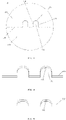
FIG. 1 is a schematic perspective structural view of an implementation of a core body according to an embodiment of the present disclosure; -
FIG. 2 is a schematic perspective structural view of an implementation of an outer housing according to an embodiment of the present disclosure; -
FIG. 3 is a schematic structural side view of an implementation of the outer housing according to the embodiment of the present disclosure; -
FIG. 4 is a schematic partial enlarged view of part A inFIG. 3 ; -
FIG. 5 is a schematic view of an implementation of cooperation between an gas blocking portion and a groove portion in an embodiment of the present disclosure; -
FIG. 6 is a schematic view of another implementation of cooperation between the gas blocking portion and the groove portion in the embodiment of the present disclosure; -
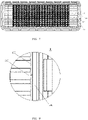
FIG. 7 is a schematic structural front view of an implementation of the core body according to the embodiment of the present disclosure; -
FIG. 8 is a schematic partial enlarged view of part B inFIG. 7 ; -
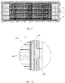
FIG. 9 is a schematic structural front view of another implementation of the core body according to the embodiment of the present disclosure; and -
FIG. 10 is a schematic partial enlarged view of part C inFIG. 9 . - Reference numerals:
100-outer housing; 110-first housing; 120-second housing; 130-gas blocking portion; 131-edge; 132-arc-shaped guide surface; 140-seam; 200-main plate; 300-chip; 310-flange; 400-side plate; 500-slit; 600-groove portion. - To make the objectives, technical solutions and advantages of the embodiments of the present disclosure clearer, the technical solutions of the present disclosure are clearly and completely described with reference to the drawings, and apparently, the described embodiments are not all but a part of the embodiments of the present disclosure. All other embodiments obtained by a person of ordinary skill in the art based on the embodiments of the present disclosure without creative efforts shall fall within the protection scope of the present disclosure.
- Accordingly, the following detailed description of the embodiments of the present disclosure provided in the drawings is not intended to limit the scope of protection of the present disclosure, but only represents selected embodiments of the present disclosure. All other embodiments obtained by a person of ordinary skill in the art based on the embodiments of the present disclosure without creative efforts shall fall within the protection scope of the present disclosure.
- In descriptions of the present disclosure, it should be noted that, directions or positional relationships indicated by terms "inner", "outer" etc. are based on orientations or positional relationships shown in the drawings, and they are used only for describing the present disclosure and for description simplicity, but do not indicate or imply that an indicated device or element must have a specific orientation or be constructed and operated in a specific orientation. Therefore, it cannot be understood as a limitation on the present disclosure. In addition, the terms such as "first" and "second" are only used for purposes of description and are not intended to indicate or imply importance in relativity.
- In the description of the present disclosure, it should be noted that unless specified or limited otherwise, the terms "mounted", "connected", and "coupled" and the like are used broadly, and it may be, for example, fixed connection, detachable connection, or integral connection; may also be mechanical connection or electrical connection; may also be direct connection or indirect connection via intermediate medium; may also be inner communication between two elements. The specific meaning of above terms in the present disclosure can be understood by those skilled in the art according to specific situations.
- It should be noted that features in embodiments of the present disclosure may be combined with each other without conflicts.
- As shown in
FIGS. 1 to 10 , one aspect of the present disclosure provides anouter housing 100, aseam 140 extending in the first direction is formed on theouter housing 100, andgas blocking portions 130 penetrating through theseam 140 are formed at theseam 140. In other words, thegas blocking portions 130 extend in the thickness direction of theseam 140, and thegas blocking portions 130 block a part of theseam 140 in the extension direction of theseam 140, such that gas flowing in theseam 140 in the extension direction of theseam 140 is blocked by thegas blocking portions 130, thereby alleviating the leakage degree of gas. In the above, the thickness direction of theseam 140 is the direction of the distance between the two independent walls forming theseam 140. That is, when the two independent walls are attached to each other, the distance between the two independent walls is zero, and at this time, the thickness of theseam 140 is zero; and when the two independent walls move away from each other, the distance increases, and the thickness of theseam 140 increases. - It should be noted that the
seam 140 in the embodiment of the present disclosure may be a welding seam formed on theouter housing 100, or a bonding line formed by tightly attaching twoseparate edges 131 of theouter housing 100, or theseam 140 is a crack formed in the manufacturing process of theouter housing 100. - In the
outer housing 100 according to the embodiment of the present disclosure, when gas leakage appears at theseam 140, since thegas blocking portion 130 penetrates through theseam 140, and thegas blocking portion 130 protrudes at theseam 140, the gas may be blocked by thegas blocking portion 130 when flowing to thegas blocking portion 130, so as to limit the flow rate of leaked gas to a certain extent, thereby alleviating the leakage degree of gas. - Optionally, the
outer housing 100 includes afirst housing 110 and asecond housing 120 abutting each other to form theseam 140, and thefirst housing 110, theseam 140, and thesecond housing 120 are arranged in sequence in the second direction, wherein the second direction and the first direction have an included angle, for example, the first direction is perpendicular to the second direction. Meanwhile, the thickness direction of theseam 140 may be parallel to the second direction. - Optionally, the
gas blocking portion 130 extends in the second direction, or the extension direction of thegas blocking portion 130 is inclined relative to the second direction. - On the
housing 100, theseam 140 formed by abutting of thefirst housing 110 and thesecond housing 120 is a long seam on theouter housing 100, and has a relatively large leakage risk, and thegas blocking portion 130 is provided at theseam 140 formed by abutting of thefirst housing 110 and thesecond housing 120, so as to better play its gas blocking effect, thus achieving a more obvious gas leakage alleviation effect; and certainly, thegas blocking portion 130 may be provided at other possible seam structures on theouter housing 100. - It should be understood that the
first housing 110 and thesecond housing 120 are both U-shaped housings, and thefirst housing 110 and thesecond housing 120 abut each other to form twoseams 140 extending in the same direction. - Optionally, at least two
gas blocking portions 130 are provided at eachseam 140, and the at least twogas blocking portions 130 are arranged in the first direction. When gas leaks from theseam 140, no matter in the first direction or the direction perpendicular to the first direction, thegas blocking portion 130 may effectively block leaked airflow, and the number of thegas blocking portions 130 is at least two, thus achieving a better airflow blocking effect. - It should be understood that the number of the
gas blocking portions 130 may be 2 to 5, for example, the number of thegas blocking portions 130 is 2, 3, or 5. - Optionally, the
gas blocking portion 130 is integrally formed on thefirst housing 110. Integral formation of thegas blocking portion 130 and thefirst housing 110 may avoid a connecting trace at the position where thegas blocking portion 130 is connected with thefirst housing 110, and thus avoids the possibility that the gas leaks from the connecting trace. - Meanwhile, due to the integral formation of the
gas blocking portion 130 on thefirst housing 110, the strength is high at the connection position of thegas blocking portion 130 and thefirst housing 110, thus reducing the risk that thegas blocking portion 130 is broken possibly at the formation position; moreover, the integral formation avoids the step of assembling thegas blocking portion 130 and thefirst housing 110, thus simplifying the production process, reducing the labor strength, and improving the production efficiency. Thegas blocking portion 130 may be a convex structure formed on thefirst housing 110, and the convex structure may be a sheet-shaped structure, a plate-shaped structure, a block-shaped structure, or the like. Certainly, thegas blocking portion 130, thefirst housing 110 and thesecond housing 120 may be formed separately and then connected; for example, the separately producedgas blocking portion 130 may be welded at corresponding positions of thefirst housing 110 and thesecond housing 120 where theseam 140 is formed, or thegas blocking portion 130 may be fixed by means of threaded connection at the corresponding positions of thefirst housing 110 and thesecond housing 120 where theseam 140 is formed. - As shown in
FIG. 6 , optionally, agroove portion 600 cooperating with thegas blocking portion 130 to accommodate thegas blocking portion 130 is formed on thesecond housing 120. When thefirst housing 110 abuts thesecond housing 120, thegas blocking portion 130 is clamped/engaged in thegroove portion 600, such that thegas blocking portion 130 may be prevented from hindering the abutment between thefirst housing 110 and thesecond housing 130, and then, the twoedges 131 of theseam 140 formed between thefirst housing 110 and thesecond housing 120 may be attached tightly to each other, thus reducing a gas leakage risk. - Optionally, the two
side edges 131 of thegas blocking portion 130 in the first direction are both attached to the inner wall of thegroove portion 600. Therefore, after thefirst housing 110 and thesecond housing 120 are spliced, the airflow (particularly the airflow flowing in the length direction of the seam 140) is difficult to leak from the connection position of thegas blocking portion 130 and thegroove portion 600, thus reducing the risk of gas leakage in an intercooler; certainly, the twoside edges 131 of thegas blocking portion 130 in the first direction may not be attached to the inner wall of thegroove portion 600, such that a gap is left between thegas blocking portion 130 and the inner wall of thegroove portion 600 and the gap is sealed by solder or other sealing structures. - Furthermore, the effect of blocking the airflow may also be achieved when one
side edge 131 of the twoside edges 131 of thegas blocking portion 130 in the first direction is attached to the inner wall of thegroove portion 600. - It should be understood that, when the
gas blocking portion 130 has a plate shape or a block shape, thegas blocking portion 130 has a certain thickness, and the thickness direction of thegas blocking portion 130 is a direction perpendicular to a plane defined by the first direction and the second direction; at this point, both side surfaces of thegas blocking portion 130 in the first direction are planes, and thegas blocking portion 130 is attached to the inner wall of thegroove portion 600; that is, both side surfaces of thegas blocking portion 130 are attached to the inner wall of thegroove portion 600, so as to form a surface sealing structure, thus achieving a good sealing effect. - As shown in
FIG. 5 , optionally, the twoside edges 131 of thegas blocking portion 130 linearly extend in the second direction. When aslit 500 which may cause gas leakage occurs at theseam 140 between thefirst housing 110 and thesecond housing 120, for example, thefirst housing 110 and thesecond housing 120 move relatively in the second direction, such that thefirst housing 110 and thesecond housing 120 move away from each other in the second direction, and at this point, theslit 500 increases; since the twoside edges 131 of thegas blocking portion 130 in the first direction are attached to the inner wall of thegroove portion 600 and the twoside edges 131 of thegas blocking portion 130 linearly extend in the second direction, the twoside edges 131 of thegas blocking portion 130 in the first direction may be always attached to the inner wall of thegroove portion 600 even when thefirst housing 110 and thesecond housing 120 move away from each other in the second direction, such that the airflow (particularly the airflow flowing in the length direction of the seam 140) is difficult to pass over thegas blocking portion 130 and leak between thegas blocking portion 130 and the inner wall of thegroove portion 600, thus improving the effect of blocking the leaked gas. - It should be understood that, as shown in
FIG. 6 , the twoside edges 131 of thegas blocking portion 130 in the first direction may be inclined relative to each other. - Optionally, the end surface of one end of the
gas blocking portion 130 apart from thefirst housing 110 in the second direction is an arc-shapedguide surface 132, and the arc-shapedguide surface 132 is located between the twoside edges 131 and meanwhile smoothly connected with the twoside edges 131; specifically, the width of the arc-shapedguide surface 132 in the first direction decreases gradually in the direction apart from thefirst housing 110; during assembly of thefirst housing 110 and thesecond housing 120, the end of the arc-shapedguide surface 132 apart from thefirst housing 110 is inserted into thegroove portion 600 on thesecond housing 120 first, and since the end of the arc-shapedguide surface 132 apart from thefirst housing 110 has a smallest width, insertion of thegas blocking portion 130 into thegroove portion 600 is facilitated. When gradually inserted into the above-mentionedgroove portion 600, thegas blocking portion 130 may be guided by the arc-shapedguide surface 132, thereby improving the assembly efficiency; for the guide effect of the arc-shapedguide surface 132, the arc-shapedguide surface 132 protrudes in the direction apart from thefirst housing 110 in the second direction; that is, the arc-shapedguide surface 132 is a convex surface (i.e. a surface protruding outwards); certainly, the arc-shaped guide surface may also be an inclined surface provided obliquely relative to the second direction. - Another aspect of the present disclosure provides a core body, including the
outer housing 100 according to the embodiment of the present disclosure. - The
outer housing 100 according to the above-mentioned embodiment of the present disclosure is adopted in the core body according to the embodiment of the present disclosure, and when gas leakage appears at theseam 140, since thegas blocking portion 130 penetrates through theseam 140, the gas may be blocked by thegas blocking portion 130 when flowing to thegas blocking portion 130, so as to limit the flow rate of leaked gas to a certain extent, thereby alleviating the leakage degree of gas. - Optionally, the core body according to the embodiment of the present disclosure includes a sealing piece located on the inner side of the
outer housing 100, the sealing piece covers theseam 140 and thegas blocking portions 130, and the sealing piece is hermetically connected with theouter housing 100 at theseam 140; that is, the sealing piece seals the side of theseam 140 located on the inner side of theouter housing 100. Therefore, when aslit 500 causing gas leakage appears at theseam 140, gas is difficult to leak outwards from the core body in the direction perpendicular to the first direction, gas flowing in the extension direction of theseam 140 may be blocked by thegas blocking portion 130, and the flow rate of the leaked gas is further reduced under the combined action of the sealing piece and thegas blocking portion 130; moreover, thefirst housing 110, thesecond housing 120 and thegas blocking portions 130 are connected by theflange 310 of achip 300 to form a whole, such that thefirst housing 110 and thesecond housing 120 have more stable relative positions and thefirst housing 110 and thesecond housing 120 are difficult to move relatively, and thus, the possibility that theslit 500 causing gas leakage appears at theseam 140 is reduced, the gas leakage possibility of an intercooler is reduced, and the intercooler runs more safely and reliably. - As shown in
FIGS. 7 and 8 , optionally, the core body according to the embodiment of the present disclosure includes achip 300 located inside theouter housing 100, the sealing piece is thechip 300, thechip 300 has aflange 310, and theflange 310 is hermetically connected with theouter housing 100 at theseam 140. Thechip 300 is an essential component in the core body, and the cost increased by providing another component as the sealing piece may be avoided by directly providing thechip 300 as the sealing piece, the mounting space is saved, and the layout of the core body is facilitated; specifically, theflange 310 may be welded to thefirst housing 110, thesecond housing 120, and thegas blocking portions 130 to achieve a sealing effect. - It should be understood that the
flange 310 is fixedly welded to thefirst housing 110, thesecond housing 120 and thegas blocking portion 130 at the same time, such that the overall structural strength is high, it is not easy to loosen or have failed connection at the connection position, thefirst housing 110 and thesecond housing 120 have firm positions and are difficult to move relatively, theslit 500 is not easy to form, and the leakage-proof effect is good. - As shown in
FIGS. 9 and 10 , optionally, the core body according to the embodiment of the present disclosure includes achip 300 and aside plate 400 located in theouter housing 100, theside plate 400 is connected with theouter housing 100 and thechip 300, and theside plate 400 is provided as the sealing piece. When the above-mentionedchip 300 is used as the sealing piece, although the cost may be reduced, theflange 310 of thechip 300 is required to be guaranteed to have a certain size in the second direction, so as to ensure that theflange 310 may cover theseam 140 and thegas blocking portion 130 at the same time, which increases the size of thechip 300 in the second direction, and after a plurality ofchips 300 are stacked to form the core body, the size of the core body in the second direction is also increased to a certain extent, such that the core body has an increased volume and is inconvenient to mount; by using theside plate 400 as the sealing piece, theflange 310 is not required to cover theseam 140 and thegas blocking portion 130, and the size of theflange 310 in the second direction may be reduced appropriately, thus reducing the size of the core body in the second direction, and facilitating miniaturization of the intercooler. - A third aspect of the present disclosure provides an intercooler, including the core body according to the embodiment of the present disclosure.
- The core body according to the above-mentioned embodiment of the present disclosure is adopted in the intercooler according to the embodiment of the present disclosure, and when gas leakage appears at the
seam 140 of theouter housing 100, since thegas blocking portion 130 penetrates through theseam 140, the gas may be blocked by thegas blocking portion 130 when flowing to thegas blocking portion 130, so as to limit the flow rate of leaked gas to a certain extent, thereby alleviating the leakage degree of gas. - Referring to
FIG. 10 , optionally, the intercooler according to the embodiment of the present disclosure includes amain plate 200 mounted on theouter housing 100, and themain plate 200 covers the gas blocking portion 130s and is hermetically connected with thegas blocking portions 130. - In the intercooler according to the embodiment of the present disclosure, the
main plate 200 is sleeved over the core body, a chamber body is connected with the core body by themain plate 200, and in order to avoid leakage of airflow between themain plate 200 and the core body, themain plate 200 is hermetically connected with theouter housing 100 of the core body; when themain plate 200 covers thegas blocking portions 130 from the outer side of theouter housing 100, thefirst housing 110, thesecond housing 120 and thegas blocking portions 130 may be tightly connected to form a whole, such that thefirst housing 110 and thesecond housing 120 are difficult to move relative to each other, and then, aslit 500 causing gas leakage is difficult to occur at theseam 140, thus reducing the gas leakage possibility of the intercooler. - When the above-mentioned sealing piece is adopted in the core body according to the embodiment of the present disclosure, that is, the sealing piece covers the
seam 400 and thegas blocking portions 130 from the inner side of theouter housing 100, and themain plate 200 covers thegas blocking portions 130 and theseam 400 from the outer side of theouter housing 100, if thefirst housing 110 and thesecond housing 120 move relative to each other and theslit 500 is formed at theseam 140, the gas is blocked in the direction perpendicular to theseam 140 by the sealing piece, themain plate 200 and thegas blocking portions 130, such that the airflow cannot flow in the direction; the airflow flowing along theseam 140 is blocked by thegas blocking portions 130, and then, by the structure formed by themain plate 200, the sealing piece and thegas blocking portions 130, the gas in the intercooler is blocked when theslit 500 appears at theseam 140, such that the gas is difficult to leak from the intercooler. - Moreover, when the above-mentioned sealing piece is adopted, and meanwhile, the groove portion 600 is formed on the outer housing 100, if the slit 500 appears at the seam 140 and the gap is formed between the gas blocking portion 130 and the groove portion 600, the flow speed of the airflow flowing in the slit 500 above and the gap is gradually reduced due to the blockage of the gas blocking portion 130 and the groove portion 600, and the airflow is finally difficult to leak from the above-mentioned gap; especially, when at least two gas blocking portions 130 and at least two groove portions 600 are provided correspondingly, the above-mentioned gaps are communicated with each other by the above-mentioned slits 500 to form fine passages between the main plate 200 and the sealing piece, and the airflow is required to flow by a long distance in the fine passages before flowing out of the intercooler; the flow speed is gradually reduced due to the blockage of each gas blocking portion 130 and each groove portion 600 during the flowing of the airflow, and the airflow is finally difficult to flow out of the intercooler; if both side edges 131 of the gas blocking portion 130 in the first direction are attached to the inner wall of the groove portion 600 at the same time, the possibility that the above-mentioned gap appears between the gas blocking portion 130 and the groove portion 600 is avoided, such that the gas is more difficult to leak from the seam 140, and the effect of sealing the gas is achieved.
- Finally, it should be noted that the above embodiments are only used to illustrate the technical solutions of the present disclosure, not to limit the present disclosure; although the present disclosure is described in detail with reference to the above embodiments, those having ordinary skill in the art should understand that they still can modify technical solutions recited in the aforesaid embodiments or equivalently replace partial or all technical features therein; these modifications or substitutions do not make essence of corresponding technical solutions depart from the scope of technical solutions of embodiments of the present disclosure.
- In addition, it should be understood by those skilled in the art that although some embodiments as discussed above comprise some features comprised in other embodiments rather than other features, combinations of features in different embodiments mean that the combinations are within the scope of the present disclosure and forms different embodiments. For example, in the claims, any one of the embodiments for which the protection is sought can be used in any combination manner. In addition, the information disclosed in this Background Art section is only for enhancement of understanding of the general background of the present disclosure and should not be taken as an acknowledgement or any form of suggestion that this information forms the prior art already known to a person skilled in the art.
- To sum up, the present disclosure provides the outer housing, the core body, and the intercooler, the leak-proofness/sealing property is good, and the gas is difficult to leak.
Claims (20)
- An outer housing, wherein at least one seam extending in a first direction is formed on the outer housing, and at least one gas blocking portion penetrating through the at least one seam is formed at the at least one seam.
- The outer housing according to claim 1, comprising a first housing and a second housing abutting each other to form the at least one seam, wherein the first housing, the at least one seam, and the second housing are arranged in sequence in a second direction; and
the at least one gas blocking portion extends in the second direction, or an extension direction of the at least one gas blocking portion is inclined relative to the second direction, and the first direction and the second direction have an included angle. - The outer housing according to claim 1 or 2, wherein a number of the at least one gas blocking portion is at least two, and the at least two gas blocking portions are arranged in the first direction.
- The outer housing according to claim 2 or 3, wherein the at least one gas blocking portion and the first housing are integrally formed.
- The outer housing according to claim 4, wherein the at least one gas blocking portion each has a sheet-shaped, plate-shaped or block-shaped convex structure.
- The outer housing according to claim 4 or 5, wherein at least one groove portion configured for cooperating with the at least one gas blocking portion to accommodate the at least one gas blocking portion is provided on the second housing.
- The outer housing according to claim 6, wherein two side edges of the at least one gas blocking portion in the first direction are attached to an inner wall of the at least one groove portion.
- The outer housing according to claim 7, wherein the two side edges linearly extend in the second direction.
- The outer housing according to claim 7, wherein the two side edges are inclined relative to each other.
- The outer housing according to any one of claims 4 to 9, wherein an end surface of one end of the at least one gas blocking portion apart from the first housing in the second direction is an arc-shaped guide surface, and the arc-shaped guide surface is connected with the two side edges.
- The outer housing according to claim 10, wherein a width of the arc-shaped guide surface in the first direction decreases gradually in a direction apart from the first housing.
- The outer housing according to any one of claims 4 to 9, wherein an end surface of one end of the at least one gas blocking portion apart from the first housing in the second direction is a guide inclined surface, and the guide inclined surface is connected with the two side edges.
- A core body, comprising the outer housing according to any one of claims 1 to 12.
- The core body according to claim 13, comprising a sealing piece located on an inner side of the outer housing, wherein the sealing piece covers both the at least one seam and the at least one gas blocking portion, and the sealing piece is hermetically connected with the outer housing at the at least one seam.
- The core body according to claim 14, wherein the sealing piece is configured as a chip located in the outer housing, the chip has a flange, and the flange is hermetically connected with the outer housing at the at least one seam.
- The core body according to claim 14, comprising a chip and a side plate located in the outer housing, wherein the side plate is connected with the outer housing and the chip, and the side plate serves as the sealing piece.
- The core body according to any one of claims 14 to 16, wherein the sealing piece is fixedly welded to the outer housing.
- An intercooler, comprising the core body according to any one of claims 13 to 17.
- The intercooler according to claim 18, comprising a main plate mounted on the outer housing, wherein the main plate covers the at least one gas blocking portion and is hermetically connected with the at least one gas blocking portion.
- The intercooler according to claim 19, wherein the main plate is provided on an outer side of the outer housing, and seals a side of the at least one seam located on the outer side of the outer housing.
Applications Claiming Priority (2)
| Application Number | Priority Date | Filing Date | Title |
|---|---|---|---|
| CN201911420834.7A CN111042909B (en) | 2019-12-31 | 2019-12-31 | Shell, core and intercooler |
| PCT/CN2020/139708 WO2021136113A1 (en) | 2019-12-31 | 2020-12-25 | Outer housing, core body, and intercooler |
Publications (3)
| Publication Number | Publication Date |
|---|---|
| EP4086441A1 true EP4086441A1 (en) | 2022-11-09 |
| EP4086441A4 EP4086441A4 (en) | 2023-07-05 |
| EP4086441B1 EP4086441B1 (en) | 2026-05-06 |
Family
ID=70243175
Family Applications (1)
| Application Number | Title | Priority Date | Filing Date |
|---|---|---|---|
| EP20911227.5A Active EP4086441B1 (en) | 2019-12-31 | 2020-12-25 | Outer housing, core body, and intercooler |
Country Status (3)
| Country | Link |
|---|---|
| EP (1) | EP4086441B1 (en) |
| CN (1) | CN111042909B (en) |
| WO (1) | WO2021136113A1 (en) |
Families Citing this family (4)
| Publication number | Priority date | Publication date | Assignee | Title |
|---|---|---|---|---|
| CN111042909B (en) * | 2019-12-31 | 2024-11-01 | 浙江银轮机械股份有限公司 | Shell, core and intercooler |
| CN111141164B (en) * | 2019-12-31 | 2024-06-25 | 浙江银轮机械股份有限公司 | Main board of intercooler, intercooler and manufacturing method of intercooler |
| CN112432518B (en) * | 2020-11-12 | 2024-02-20 | 三花控股集团有限公司 | Heat exchanger and heat exchange assembly |
| CN116591872B (en) * | 2023-05-15 | 2025-08-05 | 西安科美实业控股有限公司 | A gas engine branch air intake booster device installation structure |
Family Cites Families (18)
| Publication number | Priority date | Publication date | Assignee | Title |
|---|---|---|---|---|
| JP3956097B2 (en) * | 2002-01-07 | 2007-08-08 | 株式会社デンソー | Exhaust heat exchanger |
| CN101688763B (en) * | 2007-04-11 | 2014-08-20 | 贝洱两合公司 | Heat exchanger |
| ES2392302B1 (en) * | 2009-11-30 | 2013-10-23 | Valeo Térmico, S.A. | HEAT EXCHANGER OF STACKED PLATES. |
| DE102010040983A1 (en) * | 2010-09-17 | 2012-03-22 | Behr Gmbh & Co. Kg | Gas cooler e.g. indirect intercooler, for motor car, has locking element connected with end edge of housing portions and completely penetrating through pipe base in region of outer pipe in direction of pipes |
| CN104976818B (en) * | 2014-04-08 | 2018-10-19 | 杭州三花研究院有限公司 | Heat exchanger assembly and its application |
| WO2015164968A1 (en) * | 2014-04-29 | 2015-11-05 | Dana Canada Corporation | Charge air cooler with multi-piece plastic housing |
| WO2016133229A1 (en) * | 2015-02-16 | 2016-08-25 | 주식회사 다우정밀 | Coolant fluid channel type egr cooler |
| JP6296202B2 (en) * | 2015-03-02 | 2018-03-20 | 株式会社デンソー | Heat exchanger |
| EP3086075B1 (en) * | 2015-04-20 | 2020-05-06 | Borgwarner Emissions Systems Spain, S.L.U. | Heat exchange device |
| CN206386171U (en) * | 2016-10-28 | 2017-08-08 | 河南福流环保科技有限公司 | A kind of automobile exhaust gas purifying installation |
| CN106438017A (en) * | 2016-12-20 | 2017-02-22 | 贵州贵航汽车零部件股份有限公司 | Multi-process cross-flow type water-cooling intercooler |
| JP2018105535A (en) * | 2016-12-26 | 2018-07-05 | 株式会社デンソー | Intercooler |
| CN206830294U (en) * | 2017-06-06 | 2018-01-02 | 上海汽车集团股份有限公司 | Water-air intercooler with decompression function |
| CN108533383A (en) * | 2018-03-27 | 2018-09-14 | 浙江银轮机械股份有限公司 | A kind of booster-type water-air intercooler |
| CN211230612U (en) * | 2019-12-31 | 2020-08-11 | 浙江银轮机械股份有限公司 | Shell, core and intercooler |
| CN111141164B (en) * | 2019-12-31 | 2024-06-25 | 浙江银轮机械股份有限公司 | Main board of intercooler, intercooler and manufacturing method of intercooler |
| CN111042909B (en) * | 2019-12-31 | 2024-11-01 | 浙江银轮机械股份有限公司 | Shell, core and intercooler |
| CN211527179U (en) * | 2019-12-31 | 2020-09-18 | 浙江银轮机械股份有限公司 | Intercooler and mainboard thereof |
-
2019
- 2019-12-31 CN CN201911420834.7A patent/CN111042909B/en active Active
-
2020
- 2020-12-25 WO PCT/CN2020/139708 patent/WO2021136113A1/en not_active Ceased
- 2020-12-25 EP EP20911227.5A patent/EP4086441B1/en active Active
Also Published As
| Publication number | Publication date |
|---|---|
| CN111042909B (en) | 2024-11-01 |
| EP4086441A4 (en) | 2023-07-05 |
| EP4086441B1 (en) | 2026-05-06 |
| WO2021136113A1 (en) | 2021-07-08 |
| CN111042909A (en) | 2020-04-21 |
Similar Documents
| Publication | Publication Date | Title |
|---|---|---|
| EP4086441A1 (en) | Outer housing, core body, and intercooler | |
| US20200337181A1 (en) | Cold plate with flex regions between fin areas | |
| US8136819B2 (en) | Sealing structure and gasket | |
| EP3618170A1 (en) | Battery cooling component | |
| JP6296202B2 (en) | Heat exchanger | |
| CN111141164B (en) | Main board of intercooler, intercooler and manufacturing method of intercooler | |
| ES2805843T3 (en) | Fan motor for air conditioner | |
| EP3246738A1 (en) | Optical module | |
| CN211230612U (en) | Shell, core and intercooler | |
| JP2015055459A (en) | Tank structure of header plate-less heat exchanger | |
| CN115603518A (en) | electric pump | |
| WO2021175258A1 (en) | Sealing member, sealing assembly and heat exchanger | |
| CN211777697U (en) | Sealing member, sealing assembly and heat exchanger | |
| CN103814270A (en) | Side-entry fitting for heat exchanger | |
| CN211527179U (en) | Intercooler and mainboard thereof | |
| WO2021136437A1 (en) | Chip, chip assembly, core and intercooler | |
| CN212227840U (en) | Core body assembly and water-air intercooler | |
| CN106594302B (en) | Air volume adjusting valve | |
| CN112432539B (en) | Multi-stage intercooler and water channel isolating member and water channel isolating assembly thereof | |
| JP2026503297A (en) | Integrated Unit | |
| JP2019192810A (en) | Cooler | |
| CN222772434U (en) | Corner connecting piece for melamine resin board and clean board assembly | |
| CN201115106Y (en) | The combined sealing structure of the assembled outdoor cabinet | |
| US12130100B2 (en) | Heat exchanger | |
| CN218448275U (en) | Battery device |
Legal Events
| Date | Code | Title | Description |
|---|---|---|---|
| STAA | Information on the status of an ep patent application or granted ep patent |
Free format text: STATUS: THE INTERNATIONAL PUBLICATION HAS BEEN MADE |
|
| PUAI | Public reference made under article 153(3) epc to a published international application that has entered the european phase |
Free format text: ORIGINAL CODE: 0009012 |
|
| STAA | Information on the status of an ep patent application or granted ep patent |
Free format text: STATUS: REQUEST FOR EXAMINATION WAS MADE |
|
| 17P | Request for examination filed |
Effective date: 20220729 |
|
| AK | Designated contracting states |
Kind code of ref document: A1 Designated state(s): AL AT BE BG CH CY CZ DE DK EE ES FI FR GB GR HR HU IE IS IT LI LT LU LV MC MK MT NL NO PL PT RO RS SE SI SK SM TR |
|
| DAV | Request for validation of the european patent (deleted) | ||
| DAX | Request for extension of the european patent (deleted) | ||
| STAA | Information on the status of an ep patent application or granted ep patent |
Free format text: STATUS: EXAMINATION IS IN PROGRESS |
|
| A4 | Supplementary search report drawn up and despatched |
Effective date: 20230607 |
|
| RIC1 | Information provided on ipc code assigned before grant |
Ipc: F28F 9/00 20060101ALI20230601BHEP Ipc: F02B 29/04 20060101AFI20230601BHEP |
|
| 17Q | First examination report despatched |
Effective date: 20230620 |
|
| GRAP | Despatch of communication of intention to grant a patent |
Free format text: ORIGINAL CODE: EPIDOSNIGR1 |
|
| STAA | Information on the status of an ep patent application or granted ep patent |
Free format text: STATUS: GRANT OF PATENT IS INTENDED |
|
| INTG | Intention to grant announced |
Effective date: 20260116 |
|
| GRAS | Grant fee paid |
Free format text: ORIGINAL CODE: EPIDOSNIGR3 |
|
| GRAA | (expected) grant |
Free format text: ORIGINAL CODE: 0009210 |
|
| STAA | Information on the status of an ep patent application or granted ep patent |
Free format text: STATUS: THE PATENT HAS BEEN GRANTED |