EP4086435A1 - Revêtement usinable à épaisseur variable pour joints de plate-forme - Google Patents
Revêtement usinable à épaisseur variable pour joints de plate-forme Download PDFInfo
- Publication number
- EP4086435A1 EP4086435A1 EP22170329.1A EP22170329A EP4086435A1 EP 4086435 A1 EP4086435 A1 EP 4086435A1 EP 22170329 A EP22170329 A EP 22170329A EP 4086435 A1 EP4086435 A1 EP 4086435A1
- Authority
- EP
- European Patent Office
- Prior art keywords
- coating
- platform
- axial
- thickness
- seal
- Prior art date
- Legal status (The legal status is an assumption and is not a legal conclusion. Google has not performed a legal analysis and makes no representation as to the accuracy of the status listed.)
- Pending
Links
- 239000011248 coating agent Substances 0.000 title claims abstract description 85
- 238000000576 coating method Methods 0.000 title claims abstract description 85
- 239000000463 material Substances 0.000 claims description 6
- 229910010293 ceramic material Inorganic materials 0.000 claims description 3
- 239000011153 ceramic matrix composite Substances 0.000 claims description 3
- 239000007769 metal material Substances 0.000 claims description 2
- 238000007789 sealing Methods 0.000 description 8
- 239000000446 fuel Substances 0.000 description 5
- 238000001816 cooling Methods 0.000 description 4
- 230000008901 benefit Effects 0.000 description 3
- 230000009467 reduction Effects 0.000 description 3
- 230000003068 static effect Effects 0.000 description 3
- 241000270299 Boa Species 0.000 description 2
- VYPSYNLAJGMNEJ-UHFFFAOYSA-N Silicium dioxide Chemical compound O=[Si]=O VYPSYNLAJGMNEJ-UHFFFAOYSA-N 0.000 description 2
- XUIMIQQOPSSXEZ-UHFFFAOYSA-N Silicon Chemical compound [Si] XUIMIQQOPSSXEZ-UHFFFAOYSA-N 0.000 description 2
- MCMNRKCIXSYSNV-UHFFFAOYSA-N Zirconium dioxide Chemical compound O=[Zr]=O MCMNRKCIXSYSNV-UHFFFAOYSA-N 0.000 description 2
- 239000000919 ceramic Substances 0.000 description 2
- 230000003746 surface roughness Effects 0.000 description 2
- 241000588731 Hafnia Species 0.000 description 1
- BPQQTUXANYXVAA-UHFFFAOYSA-N Orthosilicate Chemical compound [O-][Si]([O-])([O-])[O-] BPQQTUXANYXVAA-UHFFFAOYSA-N 0.000 description 1
- 230000004888 barrier function Effects 0.000 description 1
- 230000008859 change Effects 0.000 description 1
- 229910017052 cobalt Inorganic materials 0.000 description 1
- 239000010941 cobalt Substances 0.000 description 1
- GUTLYIVDDKVIGB-UHFFFAOYSA-N cobalt atom Chemical compound [Co] GUTLYIVDDKVIGB-UHFFFAOYSA-N 0.000 description 1
- 238000002485 combustion reaction Methods 0.000 description 1
- 238000004891 communication Methods 0.000 description 1
- 239000002131 composite material Substances 0.000 description 1
- 230000006835 compression Effects 0.000 description 1
- 238000007906 compression Methods 0.000 description 1
- 238000012937 correction Methods 0.000 description 1
- 238000000151 deposition Methods 0.000 description 1
- 238000013461 design Methods 0.000 description 1
- 239000000835 fiber Substances 0.000 description 1
- 239000002657 fibrous material Substances 0.000 description 1
- 238000000227 grinding Methods 0.000 description 1
- CJNBYAVZURUTKZ-UHFFFAOYSA-N hafnium(IV) oxide Inorganic materials O=[Hf]=O CJNBYAVZURUTKZ-UHFFFAOYSA-N 0.000 description 1
- 238000003754 machining Methods 0.000 description 1
- 238000004519 manufacturing process Methods 0.000 description 1
- 230000007246 mechanism Effects 0.000 description 1
- 238000003801 milling Methods 0.000 description 1
- 238000012986 modification Methods 0.000 description 1
- 230000004048 modification Effects 0.000 description 1
- 238000010422 painting Methods 0.000 description 1
- 230000004044 response Effects 0.000 description 1
- 229910052710 silicon Inorganic materials 0.000 description 1
- 239000010703 silicon Substances 0.000 description 1
- HBMJWWWQQXIZIP-UHFFFAOYSA-N silicon carbide Chemical compound [Si+]#[C-] HBMJWWWQQXIZIP-UHFFFAOYSA-N 0.000 description 1
- 229910010271 silicon carbide Inorganic materials 0.000 description 1
- 239000000377 silicon dioxide Substances 0.000 description 1
- 239000002002 slurry Substances 0.000 description 1
- 239000007787 solid Substances 0.000 description 1
- 239000007921 spray Substances 0.000 description 1
- 238000005507 spraying Methods 0.000 description 1
- 230000007704 transition Effects 0.000 description 1
- 238000007740 vapor deposition Methods 0.000 description 1
- 239000002759 woven fabric Substances 0.000 description 1
Images


Classifications
-
- F—MECHANICAL ENGINEERING; LIGHTING; HEATING; WEAPONS; BLASTING
- F01—MACHINES OR ENGINES IN GENERAL; ENGINE PLANTS IN GENERAL; STEAM ENGINES
- F01D—NON-POSITIVE DISPLACEMENT MACHINES OR ENGINES, e.g. STEAM TURBINES
- F01D11/00—Preventing or minimising internal leakage of working-fluid, e.g. between stages
- F01D11/005—Sealing means between non relatively rotating elements
-
- F—MECHANICAL ENGINEERING; LIGHTING; HEATING; WEAPONS; BLASTING
- F01—MACHINES OR ENGINES IN GENERAL; ENGINE PLANTS IN GENERAL; STEAM ENGINES
- F01D—NON-POSITIVE DISPLACEMENT MACHINES OR ENGINES, e.g. STEAM TURBINES
- F01D11/00—Preventing or minimising internal leakage of working-fluid, e.g. between stages
- F01D11/003—Preventing or minimising internal leakage of working-fluid, e.g. between stages by packing rings; Mechanical seals
-
- F—MECHANICAL ENGINEERING; LIGHTING; HEATING; WEAPONS; BLASTING
- F01—MACHINES OR ENGINES IN GENERAL; ENGINE PLANTS IN GENERAL; STEAM ENGINES
- F01D—NON-POSITIVE DISPLACEMENT MACHINES OR ENGINES, e.g. STEAM TURBINES
- F01D25/00—Component parts, details, or accessories, not provided for in, or of interest apart from, other groups
- F01D25/005—Selecting particular materials
-
- F—MECHANICAL ENGINEERING; LIGHTING; HEATING; WEAPONS; BLASTING
- F01—MACHINES OR ENGINES IN GENERAL; ENGINE PLANTS IN GENERAL; STEAM ENGINES
- F01D—NON-POSITIVE DISPLACEMENT MACHINES OR ENGINES, e.g. STEAM TURBINES
- F01D25/00—Component parts, details, or accessories, not provided for in, or of interest apart from, other groups
- F01D25/24—Casings; Casing parts, e.g. diaphragms, casing fastenings
- F01D25/246—Fastening of diaphragms or stator-rings
-
- F—MECHANICAL ENGINEERING; LIGHTING; HEATING; WEAPONS; BLASTING
- F01—MACHINES OR ENGINES IN GENERAL; ENGINE PLANTS IN GENERAL; STEAM ENGINES
- F01D—NON-POSITIVE DISPLACEMENT MACHINES OR ENGINES, e.g. STEAM TURBINES
- F01D9/00—Stators
- F01D9/02—Nozzles; Nozzle boxes; Stator blades; Guide conduits, e.g. individual nozzles
- F01D9/04—Nozzles; Nozzle boxes; Stator blades; Guide conduits, e.g. individual nozzles forming ring or sector
- F01D9/041—Nozzles; Nozzle boxes; Stator blades; Guide conduits, e.g. individual nozzles forming ring or sector using blades
-
- F—MECHANICAL ENGINEERING; LIGHTING; HEATING; WEAPONS; BLASTING
- F05—INDEXING SCHEMES RELATING TO ENGINES OR PUMPS IN VARIOUS SUBCLASSES OF CLASSES F01-F04
- F05D—INDEXING SCHEME FOR ASPECTS RELATING TO NON-POSITIVE-DISPLACEMENT MACHINES OR ENGINES, GAS-TURBINES OR JET-PROPULSION PLANTS
- F05D2230/00—Manufacture
- F05D2230/90—Coating; Surface treatment
-
- F—MECHANICAL ENGINEERING; LIGHTING; HEATING; WEAPONS; BLASTING
- F05—INDEXING SCHEMES RELATING TO ENGINES OR PUMPS IN VARIOUS SUBCLASSES OF CLASSES F01-F04
- F05D—INDEXING SCHEME FOR ASPECTS RELATING TO NON-POSITIVE-DISPLACEMENT MACHINES OR ENGINES, GAS-TURBINES OR JET-PROPULSION PLANTS
- F05D2240/00—Components
- F05D2240/10—Stators
- F05D2240/11—Shroud seal segments
-
- Y—GENERAL TAGGING OF NEW TECHNOLOGICAL DEVELOPMENTS; GENERAL TAGGING OF CROSS-SECTIONAL TECHNOLOGIES SPANNING OVER SEVERAL SECTIONS OF THE IPC; TECHNICAL SUBJECTS COVERED BY FORMER USPC CROSS-REFERENCE ART COLLECTIONS [XRACs] AND DIGESTS
- Y02—TECHNOLOGIES OR APPLICATIONS FOR MITIGATION OR ADAPTATION AGAINST CLIMATE CHANGE
- Y02T—CLIMATE CHANGE MITIGATION TECHNOLOGIES RELATED TO TRANSPORTATION
- Y02T50/00—Aeronautics or air transport
- Y02T50/60—Efficient propulsion technologies, e.g. for aircraft
Definitions
- a gas turbine engine typically includes a fan section, a compressor section, a combustor section, and a turbine section. Air entering the compressor section is compressed and delivered into the combustion section where it is mixed with fuel and ignited to generate a high-speed exhaust gas flow. The high-speed exhaust gas flow expands through the turbine section to drive the compressor and the fan section.
- the compressor or turbine sections may include vanes mounted on vane platforms. Seals may be arranged between matefaces of adjacent components to reduce leakage to the high pressure and high temperature gas flow.
- a flow path component assembly includes a flow path component that has a platform that extends from a first circumferential side to a second circumferential side.
- the platform has a first radius of curvature between the first circumferential side and the second circumferential side.
- a coating is arranged on a portion of the platform near the first circumferential side.
- the coating has a second radius of curvature. The second radius of curvature is larger than the first radius of curvature.
- the coating has a first thickness and a second thickness.
- the second thickness is closest to the first circumferential side.
- the second thickness is smaller than the first thickness.
- the coating has a thickness less than about 0.100 inches (2.54 mm).
- the platform extends from a first axial side to a second axial side.
- the coating extends from the first axial side to the second axial side.
- the coating has a portion between the first and second axial sides that is substantially flat in an axial direction.
- the portion extends between 25% and 70% of a distance between the first axial side and the second axial side.
- the coating has a first thickness in the portion that is smaller than an outer thickness forward or aft of the portion.
- the coating extends a circumferential distance from the first circumferential side of less than about 0.250 inches (6.35 mm).
- the platform has a radially inner surface and a radially outer surface.
- the coating is on the radially outer surface.
- the coating is configured to engage with a mateface seal.
- the platform is formed from a ceramic matrix composite material.
- the platform is a vane platform.
- the vane platform is an outer vane platform.
- a turbine section for a gas turbine engine includes a plurality of vanes arranged circumferentially about an engine axis. Each vane has a platform. Each of the platforms has a first radial side and a second radial side and extends from a first circumferential side to a second circumferential side. A coating is arranged on the first radial side along the first circumferential side and the second circumferential side. The coating has a first thickness and a second thickness that is different from the first thickness. A mateface seal arranged on the coating near the first circumferential side of a first platform and a second circumferential side of a second platform.
- the platform extends from a first axial side to a second axial side.
- the coating extends from the first axial side to the second axial side.
- the coating has a portion between the first and second axial sides that is substantially flat in an axial direction. The portion extends between 25% and 70% of a distance between the first axial side and the second axial side.
- the platform has a first radius of curvature in a circumferential direction.
- the coating has a second radius of curvature in the circumferential direction. The second radius of curvature larger than the first radius of curvature
- an axial seal extends along an axial side of the platform.
- a step is formed in the coating. At least a portion of the axial seal is arranged between the step and the mateface seal.
- a spring assembly biases the mateface seal into engagement with the coating.
- the mateface seal is a metallic material.
- At least one of the platforms is formed from a ceramic material.
- the present disclosure may include any one or more of the individual features disclosed above and/or below alone or in any combination thereof.
- FIG. 1 schematically illustrates a gas turbine engine 20.
- the gas turbine engine 20 is disclosed herein as a two-spool turbofan that generally incorporates a fan section 22, a compressor section 24, a combustor section 26 and a turbine section 28.
- the fan section 22 may include a single-stage fan 42 having a plurality of fan blades 43.
- the fan blades 43 may have a fixed stagger angle or may have a variable pitch to direct incoming airflow from an engine inlet.
- the fan 42 drives air along a bypass flow path B in a bypass duct 13 defined within a housing 15 such as a fan case or nacelle, and also drives air along a core flow path C for compression and communication into the combustor section 26 then expansion through the turbine section 28.
- a splitter 29 aft of the fan 42 divides the air between the bypass flow path B and the core flow path C.
- the housing 15 may surround the fan 42 to establish an outer diameter of the bypass duct 13.
- the splitter 29 may establish an inner diameter of the bypass duct 13.
- the exemplary engine 20 generally includes a low speed spool 30 and a high speed spool 32 mounted for rotation about an engine central longitudinal axis A relative to an engine static structure 36 via several bearing systems 38. It should be understood that various bearing systems 38 at various locations may alternatively or additionally be provided, and the location of bearing systems 38 may be varied as appropriate to the application.
- the low speed spool 30 generally includes an inner shaft 40 that interconnects, a first (or low) pressure compressor 44 and a first (or low) pressure turbine 46.
- the inner shaft 40 is connected to the fan 42 through a speed change mechanism, which in the exemplary gas turbine engine 20 is illustrated as a geared architecture 48 to drive the fan 42 at a lower speed than the low speed spool 30.
- the inner shaft 40 may interconnect the low pressure compressor 44 and low pressure turbine 46 such that the low pressure compressor 44 and low pressure turbine 46 are rotatable at a common speed and in a common direction.
- the low pressure turbine 46 drives both the fan 42 and low pressure compressor 44 through the geared architecture 48 such that the fan 42 and low pressure compressor 44 are rotatable at a common speed.
- the high speed spool 32 includes an outer shaft 50 that interconnects a second (or high) pressure compressor 52 and a second (or high) pressure turbine 54.
- a combustor 56 is arranged in the exemplary gas turbine 20 between the high pressure compressor 52 and the high pressure turbine 54.
- a mid-turbine frame 57 of the engine static structure 36 may be arranged generally between the high pressure turbine 54 and the low pressure turbine 46.
- the mid-turbine frame 57 further supports bearing systems 38 in the turbine section 28.
- the inner shaft 40 and the outer shaft 50 are concentric and rotate via bearing systems 38 about the engine central longitudinal axis A which is collinear with their longitudinal axes.
- Airflow in the core flow path C is compressed by the low pressure compressor 44 then the high pressure compressor 52, mixed and burned with fuel in the combustor 56, then expanded through the high pressure turbine 54 and low pressure turbine 46.
- the mid-turbine frame 57 includes airfoils 59 which are in the core flow path C.
- the turbines 46, 54 rotationally drive the respective low speed spool 30 and high speed spool 32 in response to the expansion.
- gear system 48 may be located aft of the low pressure compressor, or aft of the combustor section 26 or even aft of turbine section 28, and fan 42 may be positioned forward or aft of the location of gear system 48.
- the low pressure compressor 44, high pressure compressor 52, high pressure turbine 54 and low pressure turbine 46 each include one or more stages having a row of rotatable airfoils. Each stage may include a row of vanes adjacent the rotatable airfoils.
- the rotatable airfoils are schematically indicated at 47, and the vanes are schematically indicated at 49.
- the engine 20 may be a high-bypass geared aircraft engine.
- the bypass ratio can be greater than or equal to 10.0 and less than or equal to about 18.0, or more narrowly can be less than or equal to 16.0.
- the geared architecture 48 may be an epicyclic gear train, such as a planetary gear system or a star gear system.
- the epicyclic gear train may include a sun gear, a ring gear, a plurality of intermediate gears meshing with the sun gear and ring gear, and a carrier that supports the intermediate gears.
- the sun gear may provide an input to the gear train.
- the ring gear (e.g., star gear system) or carrier (e.g., planetary gear system) may provide an output of the gear train to drive the fan 42.
- a gear reduction ratio may be greater than or equal to 2.3, or more narrowly greater than or equal to 3.0, and in some embodiments the gear reduction ratio is greater than or equal to 3.4.
- the gear reduction ratio may be less than or equal to 4.0.
- the fan diameter is significantly larger than that of the low pressure compressor 44.
- the low pressure turbine 46 can have a pressure ratio that is greater than or equal to 8.0 and in some embodiments is greater than or equal to 10.0.
- the low pressure turbine pressure ratio can be less than or equal to 13.0, or more narrowly less than or equal to 12.0.
- Low pressure turbine 46 pressure ratio is pressure measured prior to an inlet of low pressure turbine 46 as related to the pressure at the outlet of the low pressure turbine 46 prior to an exhaust nozzle. It should be understood, however, that the above parameters are only exemplary of one embodiment of a geared architecture engine and that the present invention is applicable to other gas turbine engines including direct drive turbofans. All of these parameters are measured at the cruise condition described below.
- the fan section 22 of the engine 20 is designed for a particular flight condition -- typically cruise at about 0.8 Mach and about 35,000 feet (10,668 meters).
- the flight condition of 0.8 Mach and 35,000 ft (10,668 meters), with the engine at its best fuel consumption - also known as "bucket cruise Thrust Specific Fuel Consumption ('TSFC')" - is the industry standard parameter of lbm of fuel being burned divided by lbf of thrust the engine produces at that minimum point.
- 'TSFC' Thrust Specific Fuel Consumption
- Fan pressure ratio is the pressure ratio across the fan blade 43 alone, without a Fan Exit Guide Vane (“FEGV”) system.
- a distance is established in a radial direction between the inner and outer diameters of the bypass duct 13 at an axial position corresponding to a leading edge of the splitter 29 relative to the engine central longitudinal axis A.
- the fan pressure ratio is a spanwise average of the pressure ratios measured across the fan blade 43 alone over radial positions corresponding to the distance.
- the fan pressure ratio can be less than or equal to 1.45, or more narrowly greater than or equal to 1.25, such as between 1.30 and 1.40.
- the corrected fan tip speed can be less than or equal to 1150.0 ft / second (350.5 meters/second), and can be greater than or equal to 1000.0 ft / second (304.8 meters/second).
- FIG 2 shows a portion of an example turbine section 28, which may be incorporated into a gas turbine engine such as the one shown in Figure 1 .
- the turbine section 28 includes a plurality of alternating turbine blades 102 and turbine vanes 97.
- a turbine blade 102 has a radially outer tip 103 that is spaced from a blade outer air seal assembly 104 with a blade outer air seal ("BOAS") 106.
- the BOAS 106 may be mounted to an engine case or structure, such as engine static structure 36 via a control ring or support structure 110 and a carrier 112.
- the engine structure 36 may extend for a full 360° about the engine axis A.
- the turbine vane assembly 97 generally comprises a plurality of vane segments 118.
- each of the vane segments 118 has an airfoil 116 extending between an inner vane platform 120 and an outer vane platform 122.
- FIG. 3 illustrates a portion of the vane ring assembly 97 from the turbine section 28 of the engine 20.
- the vane ring assembly 97 is made up of a plurality of vanes 118 situated in a circumferential row about the engine central axis A.
- the vane segments 118 are shown and described with reference to application in the turbine section 28, it is to be understood that the examples herein are also applicable to structural vanes in other sections of the engine 20.
- the vane segment 118 has an outer platform 122 radially outward of the airfoil 116.
- Each platform 122 has radially inner and outer sides R1, R2, respectively, first and second axial sides A1, A2, respectively, and first and second circumferential sides C1, C2, respectively.
- the radially inner side R1 faces in a direction toward the engine central axis A.
- the radially inner side R1 is thus the gas path side of the outer vane platform 122 that bounds a portion of the core flow path C.
- the first axial side A1 faces in a forward direction toward the front of the engine 20 (i.e., toward the fan 42), and the second axial side A2 faces in an aft direction toward the rear of the engine 20 (i.e., toward the exhaust end).
- first axial side A1 is near the airfoil leading end 125 and the second axial side A2 is near the airfoil trailing end 127.
- the first and second circumferential sides C1, C2 of each platform 122 abut circumferential sides C1, C2 of adjacent platforms 122.
- a mateface seal is arranged between circumferential sides C1, C2 of adjacent platforms, as will be described further herein.
- a vane platform 122 may apply to other components, and particularly flow path components.
- this disclosure may apply to combustor liner panels, shrouds, transition ducts, exhaust nozzle liners, blade outer air seals, or other CMC components.
- the outer vane platform 122 is generally shown and referenced, this disclosure may apply to the inner vane platform 120.
- the vane platform 122 may be formed of a ceramic material, such as a ceramic matrix composite ("CMC") material or a monolithic ceramic.
- each platform 122 is formed of a plurality of CMC laminate sheets.
- the laminate sheets may be silicon carbide fibers, formed into a braided or woven fabric in each layer.
- the vane platform 122 may be made of a monolithic ceramic.
- CMC components such as vane platforms 120 are formed by laying fiber material, such as laminate sheets or braids, in tooling, injecting a gaseous or melt infiltrant into the tooling, and reacting to form a solid composite component. The component may be further processed by adding additional material to coat the laminate sheets.
- CMC components may have higher operating temperatures than components formed from other materials.
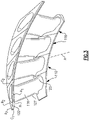
- Figure 4 illustrates a view of a portion of a platform assembly from an aft side looking forward towards the first axial side A1.
- a plurality of platforms 122A, 122B, 122C are arranged circumferentially adjacent one another.
- Each of the platforms 122A, 122B, 122C has first and second circumferential sides C1, C2 arranged adjacent circumferential sides C1, C2 of an adjacent segment.
- the first circumferential side C1 of the platform 122B is adjacent the second circumferential side C2 of the platform 122A and the second circumferential side C2 of the platform 122B is adjacent the first circumferential side C1 of the platform 122C.
- a gap G is formed between the first and second platforms 122A, 122B in the circumferential direction C.
- Each platform may have a uniform thickness 132 in a radial direction, for example.
- the platforms 122A, 122B, 122C have an outer surface 134 that is curved.
- the outer surface 134 is on the second radial side R2 (i.e., outer relative to the engine central axis), in this example.
- an outer surface 134 is discussed, the teachings of this disclosure may also apply to an inner platform, and thus an inner surface.
- Vector lines 130 show that the surface 134 is curved in both the axial direction X and the circumferential direction C.
- the vector lines 130 represent the mean vector of the curvature of the platform 122.
- the platforms 122 are twisted as a result of flowpath design, resulting in platform curvature. This platform curvature may complicate sealing the mateface gap G, and thus a coating and mateface seal are used, as described further herein
- Figure 5 illustrates a cross-sectional view of a platform assembly having a mateface seal.
- the curvature of the platform 122 may impede sealing of the gap G between adjacent platforms 122A, 122B.
- a coating 140 is arranged on the platforms 122 between the surface 134 of the platform 122 and a mateface seal 160.
- the coating 140 has a first coating surface 142 flush with the platform surface 134 and a second coating surface 144 that engages the mateface seal 160.
- the coating 140 is machinable. In some examples, the coating 140 has a lower temperature capability than the CMC platform 122.
- the coating's thermal conductivity may be tailored to limit the heat transferred to the mateface seal 160 and any other sealing components within the assembly.
- the coating 140 may be composed of elemental silicon, silicate, silica, hafnia, zirconia, or combinations thereof, in some examples.
- the coating deposition technique is not particularly limited and may be, but is not limited to, spraying or painting of slurries, vapor deposition, pack cementation, and plasma spray.
- the coating may be a plasma sprayed silicon metal.
- the coating 140 is machined to have a variable thickness between the first coating surface 142 and the second coating surface 144.
- the coating 140 may be machined via grinding, ultrasonic machining, or milling, for example.
- the coating 140 has a smaller thickness 148 closer to the gap G and a larger thickness 146 further from the gap G.
- the smaller thickness 148 is at the circumferential sides C1, C2, while a larger thickness 146 is spaced from the circumferential sides C1, C2.
- the coating 140 may be machined to form the variable thickness, for example. These different thicknesses form the outer surface 144 of the coating 140.
- the outer surface 144 has a larger radius of curvature in the circumferential direction than the surface 134 of the platform 122 for a portion of the platform 122.
- the outer surface 144 of the coating 140 may be substantially flat, in some examples.
- the thicknesses 148, 146 of the coating 140 are less than 0.100 inches (2.54 mm). In a further example, the thicknesses 148, 146 of the coating 140 are less than 0.070 inches (1.778 mm).
- the thicknesses 148, 146 may be greater than 0.005 inches (0.127 mm). In a further example, the thicknesses 148, 146 may be greater than 0.020 inches (0.508 mm). In a further example, the thicknesses 148, 146 may be greater than 0.040 inches (1.016 mm).
- the thickness of the coating 140 may be tailored based on the curvature of the platform 122.
- the mateface seal 160 is arranged on the coating and spans across the gap G between two adjacent platforms 122.
- the mateface seal 160 may be a metallic component such as a cobalt material, for example.
- the mateface seal 160 may be biased into engagement with the surface 144 of the coating 140 via a separate assembly.
- the mateface seal 160 may have a constant thickness 162. In some examples, the thickness 162 of the mateface seal 160 may be smaller than the coating thicknesses 148, 146.
- a spring assembly (shown in Figure 7 ) is used to hold the mateface seal 160 in the proper location.
- the mateface seal 160 helps to prevent leakage of cooling air through the gap G between circumferential sides C1, C2 of adjacent platforms 122A, 122B. The leakage of cooling air may come from outboard of the platform 122, such as from a vane cavity.
- Figure 6 illustrates a portion of an example vane assembly.
- the coating 140 may be arranged along the circumferential and axial edges of the platforms 122A, 122B. That is, there is a portion 174 of the platform 122A, 122B that does not have the coating 140. This portion 174 allows for impingement cooling onto the platform 122A, 122B, for example.
- the coating 140 has a first width 172 in the circumferential direction at the first circumferential side C1 and a second width 170 at the second circumferential side C2.
- the first width 172 may be larger than the second width 170, in some examples. That is, the pressure side of the airfoil platform 122 may have a smaller width 170.
- the widths 170, 172 are less than about 0.250 inches (6.35 mm).
- Figure 7 illustrates another view of the example vane platform assembly.
- the coating 140 extends from the first axial side A1 to the second axial side A2 near the circumferential edges.
- the coating 140 may also have a variable thickness in the axial direction.
- the coating has a first thickness 188 near a middle of the platform 122 in the axial direction.
- a second thickness 192 is forward of the first thickness 188 and a third thickness 190 is aft of the first thickness 188.
- the first thickness 188 may be smaller than the second and third thicknesses 192, 190.
- This arrangement provides the outer surface 134 of the coating with less curvature than the platform 122 in the axial direction.
- a portion 186 of the coating 140 is substantially flat in the axial direction X. That is, the portion 186 is substantially parallel to the engine longitudinal axis A.
- the portion 186 may have a length in the axial direction that is between 25% and 70% of a total length 184 of the platform 122.
- a spring assembly 194 may be used to hold the intersegment seal 160 in place at the circumferential sides of the platforms 122. Although a particular spring arrangement is shown, other spring arrangements may also be used.
- the coating 140, and in particular the portion 186 of the coating 140 provides a flatter surface for the spring 194 to press the intersegment seal 160 into contact with the coating 140. This may allow for better sealing effectiveness.
- the coating 140 also extends along the first and second axial sides A1, A2. In other words, the coating 140 may extend about a perimeter of the platform 122.
- the vane assembly may further include at least one axial seal 176, 178.
- a forward seal 176 and an aft seal 178 may be used at the first and second axial sides A1, A2, respectively, for sealing at the axial edges.
- the forward and aft seals 176, 178 are L-seals.
- Figure 8 illustrates a cut away view of a portion of the vane platform assembly according to an embodiment.
- a portion of the coating 140 is machined away to form a step 180.
- the step 180 accommodates the L-seal 176.
- the L-seal has a thickness 182 that is smaller than a height of the step 180.
- the step 180 allows a portion of the L-seal to be arranged between the coating 140 and the seal 160, while still permitting the seal 160 to be substantially flush with the coating 140. This arrangement constrains the L-seal in a radial direction, in some examples.
- a step 180 may be formed near the L-seal 178, in some examples.
- Mateface seals are used to limit cooling air leakage to the core flow path, which may improve engine efficiency.
- sealing challenges may arise from high curvature in the seal land area and inherent surface roughness of CMC components.
- the disclosed coating arrangement removes the complex curvature of the seal land so that the mateface seal has a surface that is not highly contoured to contact. This provides for better sealing effectiveness and manufacturing. This may also allow the spring assembly to make more uniform contact with the seal.
- the coating may create a thermal barrier between the hot CMC platform and the seal contact surface.
- the disclosed arrangement also provides lower surface roughness values at the seal land, and may incorporate geometric features to enable the sealing components to work together as a system, such as a step for an L-seal.
- the coating thickness may also be locally tailored to provide reduced overall coating thickness and reduced radial inter-platform gap between the CMC and metallic components. The coating may further reduce the need to machine features, such as a featherseal slot, directly into the CMC platform.
- generally axially means a direction having a vector component in the axial direction that is greater than a vector component in the circumferential direction
- generally radially means a direction having a vector component in the radial direction that is greater than a vector component in the axial direction
- generally circumferentially means a direction having a vector component in the circumferential direction that is greater than a vector component in the axial direction.
Landscapes
- Engineering & Computer Science (AREA)
- Mechanical Engineering (AREA)
- General Engineering & Computer Science (AREA)
- Chemical & Material Sciences (AREA)
- Materials Engineering (AREA)
- Turbine Rotor Nozzle Sealing (AREA)
Applications Claiming Priority (1)
| Application Number | Priority Date | Filing Date | Title |
|---|---|---|---|
| US17/246,912 US12000288B2 (en) | 2021-05-03 | 2021-05-03 | Variable thickness machinable coating for platform seals |
Publications (1)
| Publication Number | Publication Date |
|---|---|
| EP4086435A1 true EP4086435A1 (fr) | 2022-11-09 |
Family
ID=81388772
Family Applications (1)
| Application Number | Title | Priority Date | Filing Date |
|---|---|---|---|
| EP22170329.1A Pending EP4086435A1 (fr) | 2021-05-03 | 2022-04-27 | Revêtement usinable à épaisseur variable pour joints de plate-forme |
Country Status (2)
| Country | Link |
|---|---|
| US (1) | US12000288B2 (fr) |
| EP (1) | EP4086435A1 (fr) |
Families Citing this family (1)
| Publication number | Priority date | Publication date | Assignee | Title |
|---|---|---|---|---|
| US11988104B1 (en) * | 2022-11-29 | 2024-05-21 | Rtx Corporation | Removable layer to adjust mount structure of a turbine vane for re-stagger |
Citations (3)
| Publication number | Priority date | Publication date | Assignee | Title |
|---|---|---|---|---|
| WO2011047693A1 (fr) * | 2009-10-19 | 2011-04-28 | Siemens Aktiengesellschaft | Agencement d'aubes distributrices et moteur à turbine |
| US20170058686A1 (en) * | 2015-08-25 | 2017-03-02 | General Electric Company | Coated seal slot systems for turbomachinery and methods for forming the same |
| US20180045072A1 (en) * | 2015-04-01 | 2018-02-15 | Siemens Aktiengesellschaft | Vane segment for a gas turbine |
Family Cites Families (9)
| Publication number | Priority date | Publication date | Assignee | Title |
|---|---|---|---|---|
| FR2833035B1 (fr) * | 2001-12-05 | 2004-08-06 | Snecma Moteurs | Plate-forme d'aube de distributeur pour moteur a turbine a gaz |
| US20060110254A1 (en) * | 2004-11-24 | 2006-05-25 | General Electric Company | Thermal barrier coating for turbine bucket platform side faces and methods of application |
| RU2627997C2 (ru) * | 2012-12-20 | 2017-08-14 | Сименс Акциенгезелльшафт | СОПЛОВОЙ СЕГМЕНТ ДЛЯ ГАЗОВОЙ ТУРБИНЫ, ПОКРЫТЫЙ ПОКРЫТИЕМ MCrAlY И НАКЛАДКАМИ ТБП |
| US9896949B2 (en) * | 2014-12-23 | 2018-02-20 | United Technologies Corporation | Bonded fan platform |
| US9759079B2 (en) * | 2015-05-28 | 2017-09-12 | Rolls-Royce Corporation | Split line flow path seals |
| US10544699B2 (en) * | 2017-12-19 | 2020-01-28 | Rolls-Royce Corporation | System and method for minimizing the turbine blade to vane platform overlap gap |
| US20200141276A1 (en) | 2018-11-07 | 2020-05-07 | General Electric Company | Turbine shroud with lapped seal segments |
| US10934873B2 (en) | 2018-11-07 | 2021-03-02 | General Electric Company | Sealing system for turbine shroud segments |
| US11078802B2 (en) * | 2019-05-10 | 2021-08-03 | Rolls-Royce Plc | Turbine engine assembly with ceramic matrix composite components and end face seals |
-
2021
- 2021-05-03 US US17/246,912 patent/US12000288B2/en active Active
-
2022
- 2022-04-27 EP EP22170329.1A patent/EP4086435A1/fr active Pending
Patent Citations (3)
| Publication number | Priority date | Publication date | Assignee | Title |
|---|---|---|---|---|
| WO2011047693A1 (fr) * | 2009-10-19 | 2011-04-28 | Siemens Aktiengesellschaft | Agencement d'aubes distributrices et moteur à turbine |
| US20180045072A1 (en) * | 2015-04-01 | 2018-02-15 | Siemens Aktiengesellschaft | Vane segment for a gas turbine |
| US20170058686A1 (en) * | 2015-08-25 | 2017-03-02 | General Electric Company | Coated seal slot systems for turbomachinery and methods for forming the same |
Also Published As
| Publication number | Publication date |
|---|---|
| US20220349314A1 (en) | 2022-11-03 |
| US12000288B2 (en) | 2024-06-04 |
Similar Documents
| Publication | Publication Date | Title |
|---|---|---|
| US11466585B2 (en) | Blade outer air seal arrangement and method of sealing | |
| EP3734021B1 (fr) | Ensemble de joint externe d'étanchéité à l'air d'aube | |
| EP4067622A1 (fr) | Brides de dispositif d'obstacle à l'écoulement de composant cmc | |
| EP4086436A1 (fr) | Assemblages d'une aube statorique d'une turbine á gaz | |
| US11105215B2 (en) | Feather seal slot arrangement for a CMC BOAS assembly | |
| EP4056811A1 (fr) | Agencement de joint de surface d'accouplement avec rainures pour plateformes cmc | |
| US11624292B2 (en) | Feather seal for CMC BOAS | |
| EP3620616A1 (fr) | Guide d'écoulement d'air de refroidissement de joint d'air externe de lame cmc | |
| EP4063619A1 (fr) | Virole d' étanchéité d'un turbomoteur | |
| EP4086435A1 (fr) | Revêtement usinable à épaisseur variable pour joints de plate-forme | |
| US10989059B2 (en) | CMC BOAS arrangement | |
| US11220917B1 (en) | Diffused cooling arrangement for gas turbine engine components | |
| EP4056812A1 (fr) | Joint rainurée à chevrons | |
| EP4086434A2 (fr) | Aube en cmc avec couvercle de plateforme | |
| US11125099B2 (en) | Boas arrangement with double dovetail attachments | |
| US20240175368A1 (en) | Seal slot with coating | |
| EP4403748A1 (fr) | Étanchéité entre une composante céramique et métallique d'une motor de turbine á gaz | |
| EP4386180A1 (fr) | Revêtement d'une turbine à gaz à protection thermique | |
| EP4386181A1 (fr) | Revêtement d'une turbine à gaz à protection thermique |
Legal Events
| Date | Code | Title | Description |
|---|---|---|---|
| PUAI | Public reference made under article 153(3) epc to a published international application that has entered the european phase |
Free format text: ORIGINAL CODE: 0009012 |
|
| STAA | Information on the status of an ep patent application or granted ep patent |
Free format text: STATUS: THE APPLICATION HAS BEEN PUBLISHED |
|
| AK | Designated contracting states |
Kind code of ref document: A1 Designated state(s): AL AT BE BG CH CY CZ DE DK EE ES FI FR GB GR HR HU IE IS IT LI LT LU LV MC MK MT NL NO PL PT RO RS SE SI SK SM TR |
|
| STAA | Information on the status of an ep patent application or granted ep patent |
Free format text: STATUS: REQUEST FOR EXAMINATION WAS MADE |
|
| 17P | Request for examination filed |
Effective date: 20230509 |
|
| RBV | Designated contracting states (corrected) |
Designated state(s): AL AT BE BG CH CY CZ DE DK EE ES FI FR GB GR HR HU IE IS IT LI LT LU LV MC MK MT NL NO PL PT RO RS SE SI SK SM TR |
|
| RAP3 | Party data changed (applicant data changed or rights of an application transferred) |
Owner name: RTX CORPORATION |
|
| STAA | Information on the status of an ep patent application or granted ep patent |
Free format text: STATUS: EXAMINATION IS IN PROGRESS |
|
| 17Q | First examination report despatched |
Effective date: 20240123 |