EP4086385A1 - Pet hair removal assembly for laundry appliances - Google Patents
Pet hair removal assembly for laundry appliances Download PDFInfo
- Publication number
- EP4086385A1 EP4086385A1 EP22168694.2A EP22168694A EP4086385A1 EP 4086385 A1 EP4086385 A1 EP 4086385A1 EP 22168694 A EP22168694 A EP 22168694A EP 4086385 A1 EP4086385 A1 EP 4086385A1
- Authority
- EP
- European Patent Office
- Prior art keywords
- hair removal
- pet hair
- removal assembly
- cylindrical member
- foreign substrate
- Prior art date
- Legal status (The legal status is an assumption and is not a legal conclusion. Google has not performed a legal analysis and makes no representation as to the accuracy of the status listed.)
- Granted
Links
Images


Classifications
-
- D—TEXTILES; PAPER
- D06—TREATMENT OF TEXTILES OR THE LIKE; LAUNDERING; FLEXIBLE MATERIALS NOT OTHERWISE PROVIDED FOR
- D06F—LAUNDERING, DRYING, IRONING, PRESSING OR FOLDING TEXTILE ARTICLES
- D06F37/00—Details specific to washing machines covered by groups D06F21/00 - D06F25/00
-
- D—TEXTILES; PAPER
- D06—TREATMENT OF TEXTILES OR THE LIKE; LAUNDERING; FLEXIBLE MATERIALS NOT OTHERWISE PROVIDED FOR
- D06F—LAUNDERING, DRYING, IRONING, PRESSING OR FOLDING TEXTILE ARTICLES
- D06F58/00—Domestic laundry dryers
- D06F58/20—General details of domestic laundry dryers
- D06F58/22—Lint collecting arrangements
-
- D—TEXTILES; PAPER
- D06—TREATMENT OF TEXTILES OR THE LIKE; LAUNDERING; FLEXIBLE MATERIALS NOT OTHERWISE PROVIDED FOR
- D06F—LAUNDERING, DRYING, IRONING, PRESSING OR FOLDING TEXTILE ARTICLES
- D06F58/00—Domestic laundry dryers
- D06F58/02—Domestic laundry dryers having dryer drums rotating about a horizontal axis
- D06F58/04—Details
-
- D—TEXTILES; PAPER
- D06—TREATMENT OF TEXTILES OR THE LIKE; LAUNDERING; FLEXIBLE MATERIALS NOT OTHERWISE PROVIDED FOR
- D06F—LAUNDERING, DRYING, IRONING, PRESSING OR FOLDING TEXTILE ARTICLES
- D06F39/00—Details of washing machines not specific to a single type of machines covered by groups D06F9/00 - D06F27/00
- D06F39/02—Devices for adding soap or other washing agents
- D06F39/024—Devices for adding soap or other washing agents mounted on the agitator or the rotating drum; Free body dispensers
-
- D—TEXTILES; PAPER
- D06—TREATMENT OF TEXTILES OR THE LIKE; LAUNDERING; FLEXIBLE MATERIALS NOT OTHERWISE PROVIDED FOR
- D06F—LAUNDERING, DRYING, IRONING, PRESSING OR FOLDING TEXTILE ARTICLES
- D06F39/00—Details of washing machines not specific to a single type of machines covered by groups D06F9/00 - D06F27/00
- D06F39/10—Filtering arrangements
Definitions
- the present disclosure generally relates to a laundry appliance, and more specifically, to a pet hair removal assembly for a laundry appliance.
- a pet hair removal assembly for a laundry appliance includes a frame having a central support and legs.
- a cylindrical member is operably coupled to the central support of the frame.
- the cylindrical member defines recesses within an outer surface of the cylindrical member.
- a foreign substrate collection member is operably coupled to the cylindrical member.
- a fastener is positioned proximate each recess that operably couples the foreign substrate collection member with the cylindrical member.
- a laundry appliance includes a rotating drum that rotationally operates within a cabinet.
- a door is coupled to a front portion of the cabinet and operable to allow selective access to the rotating drum via an access opening in the front portion.
- the rotating drum rotates about a primary rotational axis.
- a cylindrical member includes a foreign substrate collection member. The cylindrical member is selectively positioned within a lower portion of the rotating drum to rotate about a secondary rotational axis that is parallel with the primary rotational axis.
- a laundry appliance includes a rotating drum that rotationally operates about a primary rotational axis.
- Lifters are attached to an interior surface of the drum.
- Rotation of the drum is configured to agitate articles being processed within the drum.
- a cylindrical member includes a foreign substrate collection member.
- the cylindrical member is selectively positioned within a lower portion of the drum to rotate about a secondary rotational axis that is parallel with the primary rotational axis. Rotation of the drum moves the lifters near an outer surface of the cylindrical member to engage the articles against the foreign substrate collection member of the cylindrical member.
- the terms “upper,” “lower,” “right,” “left,” “rear,” “front,” “vertical,” “horizontal,” and derivatives thereof shall relate to the disclosure as oriented in FIG. 1 .
- the term “front” shall refer to the surface of the element closer to an intended viewer, and the term “rear” shall refer to the surface of the element further from the intended viewer.
- the disclosure may assume various alternative orientations, except where expressly specified to the contrary.
- the specific devices and processes illustrated in the attached drawings, and described in the following specification are simply exemplary embodiments of the inventive concepts defined in the appended claims. Hence, specific dimensions and other physical characteristics relating to the embodiments disclosed herein are not to be considered as limiting, unless the claims expressly state otherwise.
- reference numeral 10 generally designates a pet hair removal assembly for a laundry appliance 12.
- the pet hair removal assembly 10 includes a frame 14 that has a central support 16 and legs 18.
- a cylindrical barrel member 20 is operably coupled to the central support 16 of the frame 14.
- the cylindrical barrel member 20 also defines recesses 22.
- At least one foreign substrate collection member 24 is operably coupled to the cylindrical barrel member 20.
- a fastener 26 is operably coupled with the foreign substrate collection member 24 and the cylindrical barrel member 20.
- the laundry appliance 12 is illustrated in FIG. 1 as a horizontal axis dryer. It is also contemplated that the constructions described herein may be applicable for a dryer and/or a combination laundry appliance.
- the laundry appliance 12 includes a cabinet 40 that has a front portion 42, a top portion 44, and sidewalls 46.
- An access opening 48 is defined by the front portion 42, and a door 50 is hingedly coupled to the front portion 42 proximate to the access opening 48.
- the door 50 is configured to provide selective access to a processing space 52 defined by a drum 54 of the laundry appliance 12.
- the door 50 may be generally circular to correspond with the access opening 48 defined by the front portion 42 of the cabinet 40.
- the door 50 is formed from a rigid, metallic material. However, it is also contemplated that the door 50 may be formed from other materials known in the art, such as plastic.
- the drum 54 is positioned within the cabinet 40 and is configured to rotate within the cabinet 40 and about a primary rotational axis 66 during a laundry cycle, described further below.
- a machine compartment 56 may be adjacent to the door 50 of the laundry appliance 12.
- the machine compartment 56 includes machine components 58 that are configured to rotate or otherwise articulate the drum 54 within the cabinet 40.
- a user interface 60 can be coupled to the top portion 44 of the cabinet 40 to select and control the various laundry cycles of the laundry appliance 12. Additionally or alternatively, the user interface 60 can be operably coupled to the cabinet 40 at any practicable location.
- the laundry appliance 12 includes a controller 62 that is operably and communicatively coupled to the user interface 60 and the machine components 58 of the laundry appliance 12.
- the controller 62 is configured with an algorithm of the laundry appliance 12 that is configured to control the rotational movement of the drum 54 during the laundry cycle.
- the access opening 48 of the processing space 52 is at least partially defined by a lint collection assembly 70 operably coupled to the front portion 42 of the laundry appliance 12.
- the lint collection assembly 70 can include a receiving body 72 that defines apertures 74 and defines a receiving opening 76 in which a removable lint trap 78 is selectively disposed.
- the lint trap 78 is configured with a plurality of holes 80 defined along a top surface 82 of the lint trap 78 and includes a mesh body 84 ( FIG. 1 ) coupled to the top surface 82.
- the lint collection assembly 70 is positioned opposite an air ventilation portion 86 partially defined by a rear wall 88 of the laundry appliance 12.
- the lint collection assembly 70 is generally curved to follow the circular configuration of the access opening 48 defined by the laundry appliance 12.
- the air ventilation portion 86 is at least partially configured to direct foreign substrates 90, such as pet hair, toward the lint collection assembly 70, and the lint collection assembly 70 is configured to collect the foreign substrates 90 on the lint trap 78.
- both the foreign substrate collection member 24 and the lint trap 78 are configured to independently and/or cooperatively collect the foreign substrates 90, such as pet hair.
- the pet hair removal assembly 10 is operably coupled to a front static surface 94 of the lint collection assembly 70.
- the frame 14 of the pet hair removal assembly 10 attaches to the front static surface 94 of the lint collection assembly 70 via the legs 18 being positioned within the apertures 74 defined by the lint collection assembly 70.
- the frame 14 of the pet hair removal assembly 10 includes a rear attachment portion 100 disposed within the processing space 52 and positioned proximate to a rear static surface 96 of the rear wall 88 of the laundry appliance 12.
- the rear attachment portion 100 is generally configured with a lower arcuate base 102 and a planar attachment portion 104 to define a generally D-shaped configuration of the rear attachment portion 100.
- the rear attachment portion 100 also includes a guide portion 106 outwardly extending from the lower arcuate base 102.
- the guide portion 106 is generally configured to selectively engage the rear static surface 96 of the rear wall 88 of the laundry appliance 12.
- the central support 16 of the frame 14 extends between a rear support having the rear attachment portion 100 and a front support having the legs 18. The central support 16 is coupled to the legs 18 via a crossbar 108.
- the rear wall 88 of the laundry appliance 12 generally defines a circular recess 110 to which the air ventilation portion 86 is operably coupled.
- the guide portion 106 of the frame 14 generally engages the circular recess 110 defined by the rear wall 88 of the laundry appliance 12 to guide and generally retain the frame 14 in a lower portion 112 of the processing space 52.
- the rear attachment portion 100 of the frame 14 is selectively disposed proximate to the rear wall 88 while remaining generally free from direct and/or fixed coupling with the laundry appliance 12.
- the frame 14 is operably coupled to the laundry appliance 12 via the legs 18 while the rear attachment portion 100 remains selectively free.
- the legs 18 are disposed within the lint collection assembly 70, which is operably coupled to the cabinet 40 of the laundry appliance 12 and is generally fixed relative to the drum 54. To accommodate the rotation of the drum 54, the rear attachment portion 100 of the frame 14 remains stationary relative to the drum 54 and is instead operably disposed proximate to the rear wall 88 of the laundry appliance 12.
- the guide portion 106 of the rear attachment portion 100 selectively engages portions of the circular recess 110 defined by the drum 54 as the drum 54 rotates within the cabinet 40. While the rear attachment portion 100 is selectively disposed within the drum 54 proximate to the circular recess 110, it is contemplated that the drum 54 moves, rotates, or otherwise articulates independently of the frame 14 of the pet hair removal assembly 10.
- the selective engagement of the guide portion 106 of the rear attachment portion 100 is configured to generally align the frame 14 within the processing space 52 during a laundry cycle of the laundry appliance 12.
- the guide portion 106 may articulate along and engage the circular recess 110 during rotation of the drum 54, while the frame 14 remains generally stationary within the processing space 52.
- the pet hair removal assembly 10 is configured to have a secondary rotational axis 92 relative to the primary rotational axis 66 defined by the drum 54.
- the secondary rotational axis 92 of the pet hair removal assembly 10 is generally achieved by the stationary coupling of the frame 14 to the lint collection assembly 70 via the apertures 74 and the free positioning of the rear attachment portion 100 proximate to the circular recess 110.
- the frame 14 remains uncoupled from the drum 54 to maintain the secondary rotational axis 92 of the pet hair removal assembly 10. In this manner, the secondary rotational axis 92 of the cylindrical barrel member 20 is offset below the primary rotational axis 66 of the drum 54.
- the cylindrical barrel member 20 is positioned to have a close engagement with a lower portion 112 of the processing space 52 defined within the drum 54.
- This closer engagement between the cylindrical barrel member 20 and the drum 54 defines a narrowed section 152 of the processing space 52.
- each rotation of the drum 54 can result in the articles 120 being moved upward by lifters 150 that are attached to an interior surface 64 of the drum 54.
- the articles 120 are then dropped from above and onto an outer surface 160 of the cylindrical barrel member 20 for the pet hair removal assembly 10.
- the articles 120 are directed around the cylindrical barrel member 20 and then through the narrowed section 152. This manipulation of the articles 120 within the drum 54 and between the cylindrical barrel member 20 and the drum 54 results in the cylindrical barrel member 20 being rotated about the secondary rotational axis 92.
- This configuration also presses the articles 120 being processed within the drum 54 against the lint collection assembly 70 of the cylindrical barrel member 20 as the articles 120 move through the narrowed section 152.
- the close engagement of the narrowed section 152 causes the surface of the drum 54 and the lifters 150 to press the articles 120 against the lint collection assembly 70, thereby promoting the transfer of particulate matter, including pet hair, from the articles 120 and to the lint collection assembly 70.
- the cylindrical barrel member 20 is operably coupled to the central support 16 of the frame 14, and is configured to rotate about the central support 16 to further define the secondary rotational axis 92 of the pet hair removal assembly 10, described further below.
- the primary rotational axis 66 of the drum 54 is defined relative to the cabinet 40 of the laundry appliance 12. While the secondary rotational axis 92 of the pet hair removal assembly 10 is generally offset from the primary rotational axis 66, the secondary rotational axis 92 is typically generally parallel with the primary rotational axis 66.
- operation of the frame can result in an adjustment of the cylindrical barrel member 20 within the drum 54. Accordingly, the secondary rotational axis 92 can be modified and manipulated relative to the primary rotational axis 66.
- the secondary rotational axis 92 of the pet hair removal assembly 10 is defined by the rotation of the cylindrical barrel member 20 operably coupled to the frame 14.
- the cylindrical barrel member 20 is disposed within the processing space 52 and is configured to engage articles 120 selectively disposed within the processing space 52. These articles 120 can include clothing items, linens, bedding, and other similar items that can be processed within a laundry appliance 12.
- the engagement of the articles 120 with the cylindrical barrel member 20 further defines the secondary rotational axis 92 of the pet hair removal assembly 10 within the processing space 52, described further herein.
- the cylindrical barrel member 20 has an engagement surface 130 that defines the recesses 22 in which the foreign substrate collection member 24 is disposed. It is also contemplated that multiple foreign substrate collection members 24 may be disposed within the recesses 22 defined along the engagement surface 130 of the cylindrical barrel member 20.
- the cylindrical barrel member 20 also defines a central channel 132 in which the central support 16 is disposed.
- a pair of bearings 134 are operably coupled to the central support 16 and the cylindrical barrel member 20 proximate to openings 136 defined by the cylindrical barrel member 20, which provide access to the central channel 132.
- the bearings 134 are configured to operably couple the cylindrical barrel member 20 with the central support 16 to smoothly articulate the cylindrical barrel member 20 about the central support 16 to define the secondary rotational axis 92.
- the bearings 134 are generally configured to glide or otherwise smoothly articulate with the central support 16, such that there is minimal rotational interference between the bearings 134 and the central support 16.
- the cylindrical barrel member 20 extends along a length L 1 of the central support 16, such that the central support 16 is generally concealed by the cylindrical barrel member 20. Additionally or alternatively, the cylindrical barrel member 20 may have a smaller configuration, such that more of the length L 1 of the central support 16 is exposed relative to the cylindrical barrel member 20.
- the bearings 134 may centrally retain the cylindrical barrel member 20 along the central support 16, such that the bearings 134 may generally assist in the rotational movement of the cylindrical barrel member 20 while minimizing lateral movement along the central support 16.
- the foreign substrate collection member 24 is operably coupled to the cylindrical barrel member 20 within at least one of the recesses 22 via the fasteners 26.
- the fasteners 26 may include a tensile fastener 26, such as a tensile spring, disposed within the recess 22. Additionally or alternatively, the fasteners 26 may include, but are not limited to, snaps, clips, screws, and other practicable fasteners 26.
- the tensile fastener 26 is configured to engage the foreign substrate collection member 24 and generally retain the foreign substrate collection member 24 in the recess 22.
- the foreign substrate collection member 24 may compress the tensile fastener 26 within the recess 22, such that the tensile fastener 26 defines a tensile force against the foreign substrate collection member 24 within the recess 22 to generally retain the foreign substrate collection member 24.
- the tensile fastener 26 also assists in the selective removal of the foreign substrate collection member 24.
- the user may compress the foreign substrate collection member 24 against the tensile fastener 26 to further collapse the tensile fastener 26 and release the foreign substrate collection member 24 from the recess 22 defined by the cylindrical barrel member 20.
- the user may remove the foreign substrate collection member 24 to clean or otherwise replace the foreign substrate collection member 24 with a foreign substrate collection member 24 that is generally free from foreign substrates and/or pet hair.
- the foreign substrate collection member 24 is illustrated as an elongated body that extends along a length L 2 of the cylindrical barrel member 20. It is also contemplated that the foreign substrate collection member 24 and the recesses 22 are intermittently disposed and defined along the length L 2 of the cylindrical barrel member 20. For example, multiple foreign substrate collection members 24 can be aligned along the length L 2 of the cylindrical barrel member 20. According to various aspects of the device, the foreign substrate collection member 24 can include a plurality of elongated surfaces. A portion of these elongated surfaces, typically at least one of the elongated surfaces, includes one or more discrete collection surfaces 170.
- the foreign substrate collection member 24 is formed from an abrasive material, such as a tacky or sticky material.
- a abrasive material such as a tacky or sticky material.
- This can include a fabric material containing a plurality of bristles 138.
- the material of the foreign substrate collection member 24 may include, but is not limited to, silicone, wool, leather, velvet, or other tacky, sticky or abrasive materials practicable for use in removing the foreign substrates 90.
- the fabric material containing the plurality of bristles 138 are utilized, the plurality of bristles 138 may be closely aligned along the foreign substrate collection member 24. Stated differently, the foreign substrate collection member 24 has a first side 140 and a second side 142, and it is contemplated that the bristles 138 are disposed along the first side 140.
- the alignment of the bristles 138 can assist in the abrasion or general engagement of the clothing item articles 120 within the processing space 52.
- the bristles 138 can be generally rigid, such that the engagement with the articles 120 results in minimal flexion of the bristles 138.
- the general rigidity of the bristles 138 assists in removal of the foreign substrates 90 from the articles 120. It is also contemplated that the bristles 138 may also retain the foreign substrates 90 that are removed from the articles 120, such that the foreign substrates 90 may be collected and retained by the bristles 138 along the foreign substrate collection member 24.
- the foreign substrates 90 may be retained on the foreign substrate collection member 24, such that the foreign substrates 90 may be selectively retained by the bristles 138.
- the bristles 138 can remove the foreign substrates 90 from the articles 120 and the foreign substrates 90 may be trapped within the bristles 138.
- the user can remove the foreign substrate collection member 24 from the cylindrical barrel member 20 by laterally translating the foreign substrate collection member 24 relative the cylindrical barrel member 20.
- the tensile fastener 26 may then compress upon lateral translation of the foreign substrate collection member 24 to loosen the retention of the foreign substrate collection member 24 in the respective recess 22.
- the user can remove the foreign substrates 90 from the bristles 138. Additionally or alternatively, the foreign substrates 90 may be removed from the foreign substrate collection member 24 via the air ventilation portion 86.
- the air ventilation portion 86 For example, during the laundry cycle, the foreign substrates 90 are collected by the bristles 138 and the articles 120 are dried, at least in part, via the air ventilation portion 86. It is contemplated that the air directed from the air ventilation portion 86 can release or otherwise remove the foreign substrates 90 collected along the foreign substrate collection member 24. The air directs the removed foreign substrates 90 toward the lint collection assembly 70, and the foreign substrates 90 are collected on the lint trap 78. The user can then remove the foreign substrates 90 collected on the lint trap 78.
- the pet hair removal assembly 10 can be selectively removed from the laundry appliance 12 depending on the articles 120 that are disposed in the processing space 52. For example, the user may deposit articles 120 that are more likely to have foreign substrates 90 disposed on the articles 120. The user may position the pet hair removal assembly 10 within the processing space 52 to engage the foreign substrate collection member 24 with the articles 120. Once the foreign substrates 90 are removed from the articles 120 and the laundry cycle is complete, it is contemplated that the pet hair removal assembly 10 may be removed from the laundry appliance 12. The selective positioning and removal of the pet hair removal assembly 10 maximizes the various uses of the laundry appliance 12.
- the lint collection assembly 70 typically collects the lint and loose foreign substrates 90. The selective addition of the pet hair removal assembly 10 to the laundry appliance 12 assists in further removing the foreign substrates 90.
- the pet hair removal assembly 10 is selectively positioned within the apertures 74 defined by the lint collection assembly 70.
- the legs 18 are disposed within the apertures 74, such that the frame 14 of the pet hair removal assembly 10 can be lifted and removed from the apertures 74.
- the guide portion 106 assists in the placement of the pet hair removal assembly 10 within the processing space 52.
- the guide portion 106 aligns the rear attachment portion 100 with the circular recess 110 defined by the rear wall 88 laundry appliance 12.
- the lower arcuate base 102 of the rear attachment portion 100 is disposed proximate to the rear wall 88.
- the secondary rotational axis 92 is defined as the frame 14 remains free from direct coupling with the drum 54.
- the frame 14 can include operable legs 18 that are operable to adjust the height of the cylindrical barrel member 20 within the rotating drum 54.
- the legs 18 can include telescoping members, or can include operable portions that allow the legs 18 to be manipulated through bending, deflection, extending or other similar operation to adjust the vertical position of the cylindrical barrel member 20 within the drum 54. It is contemplated that the positioning of the cylindrical barrel member 20 can be vertically adjusted to accommodate laundry loads of different sizes. Where a larger load of laundry is being processed or where the load of laundry includes larger or bulkier articles 120, the cylindrical barrel member 20 may require a greater clearance space relative to the rotating drum 54 and the lifters 150.
- a smaller clearance space relative to the drum 54 and the lifters 150 can be more desirable. It is contemplated that the vertical positions of the cylindrical barrel member 20 and the drum 54 can be adjusted before starting a laundry cycle.
- the frame 14 and the cylindrical barrel member 20 can include a suspension system that can operate to allow for continual and automatic manipulation of the cylindrical barrel member 20 during performance of the laundry cycle.
- the suspension system can provide for the passage of a larger article through the narrowed space. Where an article is larger than the narrowed space, the suspension system can allow for a deflection of the cylindrical barrel member 20 relative to the drum 54. This can prevent larger articles or clumps of articles from lifting the frame out of engagement with the receiving body 72 and the rear wall 88.
- the cylindrical barrel member 20 rotates as a result of the engagement with the articles 120 within the processing space 52.
- the secondary rotational axis 92 assists in the removal of the foreign substrates 90 as the articles 120 are rotated within the processing space 52 according to the primary rotational axis 66 of the drum 54.
- the articles 120 can then engage with the cylindrical barrel member 20, and the cylindrical barrel member 20 is generally rotated as a result of the engagement with the articles 120.
- the articles 120 rotate the cylindrical barrel member 20 as the articles 120 tumble within the drum 54 as a result of the primary rotational axis 66 of the drum 54. It is generally contemplated that the articles 120 may be tumbled or otherwise lifted by lifters 150 operably coupled to the drum 54.
- the lifters 150 can engage the articles 120 to reposition the articles 120 within the processing space 52.
- the lifters 150 may also assist in the engagement of the articles 120 with the pet hair removal assembly 10 by repositioning the articles 120 above, and ultimately onto, the cylindrical barrel member 20 and then through the narrowed space between the lifters and the cylindrical barrel member 20. It is contemplated that this narrowed space can be adjustable through operation of the frame. In this manner, the narrowed space can be from approximately 5 millimeters to approximately 200 millimeters and various distances therebetween.
- the engagement of the articles 120 with the cylindrical barrel member 20 results in the rotation of the cylindrical barrel member 20.
- the rotation of the cylindrical barrel member 20 may assist in the removal of the foreign substrates 90 as a result of an increased speed of engagement of the articles 120 with the foreign substrate collection member 24.
- a pet hair removal assembly for a laundry appliance includes a frame having a central support and legs.
- a cylindrical member is operably coupled to the central support of the frame.
- the cylindrical member defines recesses within an outer surface of the cylindrical member.
- a foreign substrate collection member is operably coupled to the cylindrical member.
- a fastener is positioned proximate each recess that operably couples the foreign substrate collection member with the cylindrical member.
- the foreign substrate collection member is selectively disposed within one of the recesses defined by the cylindrical member.
- the foreign substrate collection member includes a first side and a second side, and the first side includes a fabric material.
- the foreign substrate collection member is removably coupled to the cylindrical member via the fasteners.
- the fasteners include tensile springs that bias the foreign substrate collection member toward the cylindrical member.
- the foreign substrate collection member includes a plurality of elongated surfaces. A portion of the plurality of elongated surfaces includes discrete collection surfaces.
- one of the discrete collection surfaces includes a fabric material having bristles.
- the fabric material includes a plurality of bristles.
- the frame includes a front support and a rear support and the central support extending therebetween.
- the central support extends axially through the cylindrical member.
- a laundry appliance includes a rotating drum that rotationally operates within a cabinet.
- a door is coupled to a front portion of the cabinet and operable to allow selective access to the rotating drum via an access opening in the front portion.
- the rotating drum rotates about a primary rotational axis.
- a cylindrical member includes a foreign substrate collection member. The cylindrical member is selectively positioned within a lower portion of the rotating drum to rotate about a secondary rotational axis that is parallel with the primary rotational axis.
- a frame supports the cylindrical member within the rotating drum.
- the frame rests upon a front static surface and a rear static surface that are positioned proximate the front and the rear of the rotating drum, respectively.
- the cylindrical member includes recesses that receive the foreign substrate collection member.
- the foreign substrate collection member includes collection members that are selectively positioned within the recesses, respectively.
- the collection members are secured within the recesses using fasteners having tensile springs.
- each of the collection members include bristles that extend from a discrete collection surface.
- the frame includes a front support that is configured to rest upon the front static surface.
- the front static surface includes a receiving opening that selectively receives a removable lint trap.
- the frame includes a rear support having a rear attachment portion that selectively rests upon the rear static surface.
- a central support extends between the front support and the rear support of the frame. The central support extends through the cylindrical member.
- the rear attachment portion includes a lower arcuate base and a guide portion that selectively engage the rear static surface to rotationally secure the frame relative to the cabinet.
- a laundry appliance includes a rotating drum that rotationally operates about a primary rotational axis.
- Lifters are attached to an interior surface of the drum.
- Rotation of the drum is configured to agitate articles being processed within the drum.
- a cylindrical member includes a foreign substrate collection member.
- the cylindrical member is selectively positioned within a lower portion of the drum to rotate about a secondary rotational axis that is parallel with the primary rotational axis. Rotation of the drum moves the lifters near an outer surface of the cylindrical member to engage the articles against the foreign substrate collection member of the cylindrical member.
- the cylindrical member includes recesses that receive collection members of the foreign substrate collection member.
- the collection members are secured within the recesses using fasteners having tensile springs.
- each of the collection members include bristles that extend from a discrete collection surface.
Landscapes
- Engineering & Computer Science (AREA)
- Textile Engineering (AREA)
- Accessory Of Washing/Drying Machine, Commercial Washing/Drying Machine, Other Washing/Drying Machine (AREA)
Abstract
Description
- The present disclosure generally relates to a laundry appliance, and more specifically, to a pet hair removal assembly for a laundry appliance.
- According to one aspect of the present disclosure, a pet hair removal assembly for a laundry appliance includes a frame having a central support and legs. A cylindrical member is operably coupled to the central support of the frame. The cylindrical member defines recesses within an outer surface of the cylindrical member. A foreign substrate collection member is operably coupled to the cylindrical member. A fastener is positioned proximate each recess that operably couples the foreign substrate collection member with the cylindrical member.
- According to another aspect, a laundry appliance includes a rotating drum that rotationally operates within a cabinet. A door is coupled to a front portion of the cabinet and operable to allow selective access to the rotating drum via an access opening in the front portion. The rotating drum rotates about a primary rotational axis. A cylindrical member includes a foreign substrate collection member. The cylindrical member is selectively positioned within a lower portion of the rotating drum to rotate about a secondary rotational axis that is parallel with the primary rotational axis.
- According to another aspect, a laundry appliance includes a rotating drum that rotationally operates about a primary rotational axis. Lifters are attached to an interior surface of the drum. Rotation of the drum is configured to agitate articles being processed within the drum. A cylindrical member includes a foreign substrate collection member. The cylindrical member is selectively positioned within a lower portion of the drum to rotate about a secondary rotational axis that is parallel with the primary rotational axis. Rotation of the drum moves the lifters near an outer surface of the cylindrical member to engage the articles against the foreign substrate collection member of the cylindrical member.
- These and other features, advantages, and objects of the present disclosure will be further understood and appreciated by those skilled in the art by reference to the following specification, claims, and appended drawings.
- In the drawings:
-
FIG. 1 is a front perspective view of a laundry appliance of the present disclosure; -
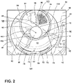
FIG. 2 is a partial front perspective view of a pet hair removal assembly of the present disclosure within a laundry cavity; -
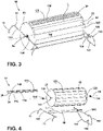
FIG. 3 is a top perspective view of a pet hair removal assembly of the present disclosure; -
FIG. 4 is an exploded top perspective view of the pet hair removal assembly ofFIG. 3 ; and -
FIG. 5 is a front perspective view of a drum for a laundry appliance with a pet hair removal assembly and clothing items positioned within a laundry cavity. - The components in the figures are not necessarily to scale, emphasis instead being placed upon illustrating the principles described herein.
- The present illustrated embodiments reside primarily in combinations of method steps and apparatus components related to a pet hair removal assembly. Accordingly, the apparatus components and method steps have been represented, where appropriate, by conventional symbols in the drawings, showing only those specific details that are pertinent to understanding the embodiments of the present disclosure so as not to obscure the disclosure with details that will be readily apparent to those of ordinary skill in the art having the benefit of the description herein. Further, like numerals in the description and drawings represent like elements.
- For purposes of description herein, the terms "upper," "lower," "right," "left," "rear," "front," "vertical," "horizontal," and derivatives thereof shall relate to the disclosure as oriented in
FIG. 1 . Unless stated otherwise, the term "front" shall refer to the surface of the element closer to an intended viewer, and the term "rear" shall refer to the surface of the element further from the intended viewer. However, it is to be understood that the disclosure may assume various alternative orientations, except where expressly specified to the contrary. It is also to be understood that the specific devices and processes illustrated in the attached drawings, and described in the following specification are simply exemplary embodiments of the inventive concepts defined in the appended claims. Hence, specific dimensions and other physical characteristics relating to the embodiments disclosed herein are not to be considered as limiting, unless the claims expressly state otherwise. - The terms "including," "comprises," "comprising," or any other variation thereof, are intended to cover a non-exclusive inclusion, such that a process, method, article, or apparatus that comprises a list of elements does not include only those elements but may include other elements not expressly listed or inherent to such process, method, article, or apparatus. An element proceeded by "comprises a . . . " does not, without more constraints, preclude the existence of additional identical elements in the process, method, article, or apparatus that comprises the element.
- Referring to
FIGS. 1-5 ,reference numeral 10 generally designates a pet hair removal assembly for alaundry appliance 12. The pethair removal assembly 10 includes aframe 14 that has acentral support 16 andlegs 18. Acylindrical barrel member 20 is operably coupled to thecentral support 16 of theframe 14. Thecylindrical barrel member 20 also definesrecesses 22. At least one foreignsubstrate collection member 24 is operably coupled to thecylindrical barrel member 20. Afastener 26 is operably coupled with the foreignsubstrate collection member 24 and thecylindrical barrel member 20. - Referring to
FIGS. 1 and2 , thelaundry appliance 12 is illustrated inFIG. 1 as a horizontal axis dryer. It is also contemplated that the constructions described herein may be applicable for a dryer and/or a combination laundry appliance. Thelaundry appliance 12 includes acabinet 40 that has afront portion 42, atop portion 44, andsidewalls 46. Anaccess opening 48 is defined by thefront portion 42, and adoor 50 is hingedly coupled to thefront portion 42 proximate to the access opening 48. Stated differently, thedoor 50 is configured to provide selective access to aprocessing space 52 defined by adrum 54 of thelaundry appliance 12. Thedoor 50 may be generally circular to correspond with the access opening 48 defined by thefront portion 42 of thecabinet 40. Typically, thedoor 50 is formed from a rigid, metallic material. However, it is also contemplated that thedoor 50 may be formed from other materials known in the art, such as plastic. - The
drum 54 is positioned within thecabinet 40 and is configured to rotate within thecabinet 40 and about a primaryrotational axis 66 during a laundry cycle, described further below. In addition, amachine compartment 56 may be adjacent to thedoor 50 of thelaundry appliance 12. Themachine compartment 56 includesmachine components 58 that are configured to rotate or otherwise articulate thedrum 54 within thecabinet 40. Auser interface 60 can be coupled to thetop portion 44 of thecabinet 40 to select and control the various laundry cycles of thelaundry appliance 12. Additionally or alternatively, theuser interface 60 can be operably coupled to thecabinet 40 at any practicable location. Thelaundry appliance 12 includes acontroller 62 that is operably and communicatively coupled to theuser interface 60 and themachine components 58 of thelaundry appliance 12. Thecontroller 62 is configured with an algorithm of thelaundry appliance 12 that is configured to control the rotational movement of thedrum 54 during the laundry cycle. - Referring now to
FIGS. 2-4 and as illustrated inFIG. 2 , the access opening 48 of theprocessing space 52 is at least partially defined by alint collection assembly 70 operably coupled to thefront portion 42 of thelaundry appliance 12. Thelint collection assembly 70 can include areceiving body 72 that definesapertures 74 and defines a receivingopening 76 in which aremovable lint trap 78 is selectively disposed. Thelint trap 78 is configured with a plurality ofholes 80 defined along atop surface 82 of thelint trap 78 and includes a mesh body 84 (FIG. 1 ) coupled to thetop surface 82. Thelint collection assembly 70 is positioned opposite anair ventilation portion 86 partially defined by arear wall 88 of thelaundry appliance 12. It is generally contemplated that thelint collection assembly 70 is generally curved to follow the circular configuration of the access opening 48 defined by thelaundry appliance 12. As will be described in more detail below, theair ventilation portion 86 is at least partially configured to directforeign substrates 90, such as pet hair, toward thelint collection assembly 70, and thelint collection assembly 70 is configured to collect theforeign substrates 90 on thelint trap 78. Stated differently, both the foreignsubstrate collection member 24 and thelint trap 78 are configured to independently and/or cooperatively collect theforeign substrates 90, such as pet hair. - Referring still to
FIGS. 2-4 , the pethair removal assembly 10 is operably coupled to a frontstatic surface 94 of thelint collection assembly 70. Theframe 14 of the pethair removal assembly 10 attaches to the frontstatic surface 94 of thelint collection assembly 70 via thelegs 18 being positioned within theapertures 74 defined by thelint collection assembly 70. Theframe 14 of the pethair removal assembly 10 includes arear attachment portion 100 disposed within theprocessing space 52 and positioned proximate to a rearstatic surface 96 of therear wall 88 of thelaundry appliance 12. Therear attachment portion 100 is generally configured with a lowerarcuate base 102 and aplanar attachment portion 104 to define a generally D-shaped configuration of therear attachment portion 100. Therear attachment portion 100 also includes aguide portion 106 outwardly extending from the lowerarcuate base 102. Theguide portion 106 is generally configured to selectively engage the rearstatic surface 96 of therear wall 88 of thelaundry appliance 12. Thecentral support 16 of theframe 14 extends between a rear support having therear attachment portion 100 and a front support having thelegs 18. Thecentral support 16 is coupled to thelegs 18 via acrossbar 108. - As mentioned above, the
rear wall 88 of thelaundry appliance 12 generally defines acircular recess 110 to which theair ventilation portion 86 is operably coupled. Theguide portion 106 of theframe 14 generally engages thecircular recess 110 defined by therear wall 88 of thelaundry appliance 12 to guide and generally retain theframe 14 in alower portion 112 of theprocessing space 52. Stated differently, therear attachment portion 100 of theframe 14 is selectively disposed proximate to therear wall 88 while remaining generally free from direct and/or fixed coupling with thelaundry appliance 12. As mentioned above, it is generally contemplated that theframe 14 is operably coupled to thelaundry appliance 12 via thelegs 18 while therear attachment portion 100 remains selectively free. Thelegs 18 are disposed within thelint collection assembly 70, which is operably coupled to thecabinet 40 of thelaundry appliance 12 and is generally fixed relative to thedrum 54. To accommodate the rotation of thedrum 54, therear attachment portion 100 of theframe 14 remains stationary relative to thedrum 54 and is instead operably disposed proximate to therear wall 88 of thelaundry appliance 12. - With further reference to
FIGS. 2-4 , theguide portion 106 of therear attachment portion 100 selectively engages portions of thecircular recess 110 defined by thedrum 54 as thedrum 54 rotates within thecabinet 40. While therear attachment portion 100 is selectively disposed within thedrum 54 proximate to thecircular recess 110, it is contemplated that thedrum 54 moves, rotates, or otherwise articulates independently of theframe 14 of the pethair removal assembly 10. The selective engagement of theguide portion 106 of therear attachment portion 100 is configured to generally align theframe 14 within theprocessing space 52 during a laundry cycle of thelaundry appliance 12. Theguide portion 106 may articulate along and engage thecircular recess 110 during rotation of thedrum 54, while theframe 14 remains generally stationary within theprocessing space 52. - It is generally contemplated that the pet
hair removal assembly 10 is configured to have a secondaryrotational axis 92 relative to the primaryrotational axis 66 defined by thedrum 54. The secondaryrotational axis 92 of the pethair removal assembly 10 is generally achieved by the stationary coupling of theframe 14 to thelint collection assembly 70 via theapertures 74 and the free positioning of therear attachment portion 100 proximate to thecircular recess 110. As discussed above, it is contemplated that theframe 14 remains uncoupled from thedrum 54 to maintain the secondaryrotational axis 92 of the pethair removal assembly 10. In this manner, the secondaryrotational axis 92 of thecylindrical barrel member 20 is offset below the primaryrotational axis 66 of thedrum 54. Accordingly, during rotation of thedrum 54, thecylindrical barrel member 20 is positioned to have a close engagement with alower portion 112 of theprocessing space 52 defined within thedrum 54. This closer engagement between thecylindrical barrel member 20 and thedrum 54 defines a narrowedsection 152 of theprocessing space 52. - In use, as the
drum 54 rotates,articles 120 being processed within thedrum 54 are directed through the narrowedsection 152 of theprocessing space 52. After moving through this narrowedsection 152, each rotation of thedrum 54 can result in thearticles 120 being moved upward bylifters 150 that are attached to aninterior surface 64 of thedrum 54. As thedrum 54 continues to rotate, thearticles 120 are then dropped from above and onto anouter surface 160 of thecylindrical barrel member 20 for the pethair removal assembly 10. As thedrum 54 continues to rotate, thearticles 120 are directed around thecylindrical barrel member 20 and then through the narrowedsection 152. This manipulation of thearticles 120 within thedrum 54 and between thecylindrical barrel member 20 and thedrum 54 results in thecylindrical barrel member 20 being rotated about the secondaryrotational axis 92. This configuration also presses thearticles 120 being processed within thedrum 54 against thelint collection assembly 70 of thecylindrical barrel member 20 as thearticles 120 move through the narrowedsection 152. The close engagement of the narrowedsection 152 causes the surface of thedrum 54 and thelifters 150 to press thearticles 120 against thelint collection assembly 70, thereby promoting the transfer of particulate matter, including pet hair, from thearticles 120 and to thelint collection assembly 70. - With reference to
FIGS. 3-5 and as mentioned above, thecylindrical barrel member 20 is operably coupled to thecentral support 16 of theframe 14, and is configured to rotate about thecentral support 16 to further define the secondaryrotational axis 92 of the pethair removal assembly 10, described further below. The primaryrotational axis 66 of thedrum 54 is defined relative to thecabinet 40 of thelaundry appliance 12. While the secondaryrotational axis 92 of the pethair removal assembly 10 is generally offset from the primaryrotational axis 66, the secondaryrotational axis 92 is typically generally parallel with the primaryrotational axis 66. As discussed herein, operation of the frame can result in an adjustment of thecylindrical barrel member 20 within thedrum 54. Accordingly, the secondaryrotational axis 92 can be modified and manipulated relative to the primaryrotational axis 66. - The secondary
rotational axis 92 of the pethair removal assembly 10 is defined by the rotation of thecylindrical barrel member 20 operably coupled to theframe 14. Thecylindrical barrel member 20 is disposed within theprocessing space 52 and is configured to engagearticles 120 selectively disposed within theprocessing space 52. Thesearticles 120 can include clothing items, linens, bedding, and other similar items that can be processed within alaundry appliance 12. The engagement of thearticles 120 with thecylindrical barrel member 20 further defines the secondaryrotational axis 92 of the pethair removal assembly 10 within theprocessing space 52, described further herein. Thecylindrical barrel member 20 has anengagement surface 130 that defines therecesses 22 in which the foreignsubstrate collection member 24 is disposed. It is also contemplated that multiple foreignsubstrate collection members 24 may be disposed within therecesses 22 defined along theengagement surface 130 of thecylindrical barrel member 20. Thecylindrical barrel member 20 also defines acentral channel 132 in which thecentral support 16 is disposed. - With further reference to
FIGS. 3-5 , a pair ofbearings 134 are operably coupled to thecentral support 16 and thecylindrical barrel member 20 proximate toopenings 136 defined by thecylindrical barrel member 20, which provide access to thecentral channel 132. Thebearings 134 are configured to operably couple thecylindrical barrel member 20 with thecentral support 16 to smoothly articulate thecylindrical barrel member 20 about thecentral support 16 to define the secondaryrotational axis 92. Thebearings 134 are generally configured to glide or otherwise smoothly articulate with thecentral support 16, such that there is minimal rotational interference between thebearings 134 and thecentral support 16. As illustrated inFIG. 3 , thecylindrical barrel member 20 extends along a length L1 of thecentral support 16, such that thecentral support 16 is generally concealed by thecylindrical barrel member 20. Additionally or alternatively, thecylindrical barrel member 20 may have a smaller configuration, such that more of the length L1 of thecentral support 16 is exposed relative to thecylindrical barrel member 20. - It is generally contemplated that the
bearings 134 may centrally retain thecylindrical barrel member 20 along thecentral support 16, such that thebearings 134 may generally assist in the rotational movement of thecylindrical barrel member 20 while minimizing lateral movement along thecentral support 16. As mentioned above, the foreignsubstrate collection member 24 is operably coupled to thecylindrical barrel member 20 within at least one of therecesses 22 via thefasteners 26. It is generally contemplated that thefasteners 26 may include atensile fastener 26, such as a tensile spring, disposed within therecess 22. Additionally or alternatively, thefasteners 26 may include, but are not limited to, snaps, clips, screws, and otherpracticable fasteners 26. Thetensile fastener 26 is configured to engage the foreignsubstrate collection member 24 and generally retain the foreignsubstrate collection member 24 in therecess 22. - For example, the foreign
substrate collection member 24 may compress thetensile fastener 26 within therecess 22, such that thetensile fastener 26 defines a tensile force against the foreignsubstrate collection member 24 within therecess 22 to generally retain the foreignsubstrate collection member 24. Thetensile fastener 26 also assists in the selective removal of the foreignsubstrate collection member 24. The user may compress the foreignsubstrate collection member 24 against thetensile fastener 26 to further collapse thetensile fastener 26 and release the foreignsubstrate collection member 24 from therecess 22 defined by thecylindrical barrel member 20. The user may remove the foreignsubstrate collection member 24 to clean or otherwise replace the foreignsubstrate collection member 24 with a foreignsubstrate collection member 24 that is generally free from foreign substrates and/or pet hair. - With further reference to
FIGS. 3-5 , the foreignsubstrate collection member 24 is illustrated as an elongated body that extends along a length L2 of thecylindrical barrel member 20. It is also contemplated that the foreignsubstrate collection member 24 and therecesses 22 are intermittently disposed and defined along the length L2 of thecylindrical barrel member 20. For example, multiple foreignsubstrate collection members 24 can be aligned along the length L2 of thecylindrical barrel member 20. According to various aspects of the device, the foreignsubstrate collection member 24 can include a plurality of elongated surfaces. A portion of these elongated surfaces, typically at least one of the elongated surfaces, includes one or more discrete collection surfaces 170. - The foreign
substrate collection member 24 is formed from an abrasive material, such as a tacky or sticky material. This can include a fabric material containing a plurality ofbristles 138. Additionally or alternatively, the material of the foreignsubstrate collection member 24 may include, but is not limited to, silicone, wool, leather, velvet, or other tacky, sticky or abrasive materials practicable for use in removing theforeign substrates 90. Where the fabric material containing the plurality ofbristles 138 are utilized, the plurality ofbristles 138 may be closely aligned along the foreignsubstrate collection member 24. Stated differently, the foreignsubstrate collection member 24 has afirst side 140 and asecond side 142, and it is contemplated that thebristles 138 are disposed along thefirst side 140. The alignment of thebristles 138 can assist in the abrasion or general engagement of theclothing item articles 120 within theprocessing space 52. Thebristles 138 can be generally rigid, such that the engagement with thearticles 120 results in minimal flexion of thebristles 138. The general rigidity of thebristles 138 assists in removal of theforeign substrates 90 from thearticles 120. It is also contemplated that thebristles 138 may also retain theforeign substrates 90 that are removed from thearticles 120, such that theforeign substrates 90 may be collected and retained by thebristles 138 along the foreignsubstrate collection member 24. - The
foreign substrates 90 may be retained on the foreignsubstrate collection member 24, such that theforeign substrates 90 may be selectively retained by thebristles 138. For example, thebristles 138 can remove theforeign substrates 90 from thearticles 120 and theforeign substrates 90 may be trapped within thebristles 138. It is contemplated that the user can remove the foreignsubstrate collection member 24 from thecylindrical barrel member 20 by laterally translating the foreignsubstrate collection member 24 relative thecylindrical barrel member 20. Thetensile fastener 26 may then compress upon lateral translation of the foreignsubstrate collection member 24 to loosen the retention of the foreignsubstrate collection member 24 in therespective recess 22. - Once the foreign
substrate collection member 24 is removed, the user can remove theforeign substrates 90 from thebristles 138. Additionally or alternatively, theforeign substrates 90 may be removed from the foreignsubstrate collection member 24 via theair ventilation portion 86. For example, during the laundry cycle, theforeign substrates 90 are collected by thebristles 138 and thearticles 120 are dried, at least in part, via theair ventilation portion 86. It is contemplated that the air directed from theair ventilation portion 86 can release or otherwise remove theforeign substrates 90 collected along the foreignsubstrate collection member 24. The air directs the removedforeign substrates 90 toward thelint collection assembly 70, and theforeign substrates 90 are collected on thelint trap 78. The user can then remove theforeign substrates 90 collected on thelint trap 78. - Referring again to
FIGS. 1-5 , it is generally contemplated that the pethair removal assembly 10 can be selectively removed from thelaundry appliance 12 depending on thearticles 120 that are disposed in theprocessing space 52. For example, the user may depositarticles 120 that are more likely to haveforeign substrates 90 disposed on thearticles 120. The user may position the pethair removal assembly 10 within theprocessing space 52 to engage the foreignsubstrate collection member 24 with thearticles 120. Once theforeign substrates 90 are removed from thearticles 120 and the laundry cycle is complete, it is contemplated that the pethair removal assembly 10 may be removed from thelaundry appliance 12. The selective positioning and removal of the pethair removal assembly 10 maximizes the various uses of thelaundry appliance 12. Thelint collection assembly 70 typically collects the lint and looseforeign substrates 90. The selective addition of the pethair removal assembly 10 to thelaundry appliance 12 assists in further removing theforeign substrates 90. - The pet
hair removal assembly 10 is selectively positioned within theapertures 74 defined by thelint collection assembly 70. Thelegs 18 are disposed within theapertures 74, such that theframe 14 of the pethair removal assembly 10 can be lifted and removed from theapertures 74. Theguide portion 106 assists in the placement of the pethair removal assembly 10 within theprocessing space 52. For example, theguide portion 106 aligns therear attachment portion 100 with thecircular recess 110 defined by therear wall 88laundry appliance 12. The lowerarcuate base 102 of therear attachment portion 100 is disposed proximate to therear wall 88. As mentioned above, the secondaryrotational axis 92 is defined as theframe 14 remains free from direct coupling with thedrum 54. - In certain aspects of the device, the
frame 14 can includeoperable legs 18 that are operable to adjust the height of thecylindrical barrel member 20 within therotating drum 54. In this manner, thelegs 18 can include telescoping members, or can include operable portions that allow thelegs 18 to be manipulated through bending, deflection, extending or other similar operation to adjust the vertical position of thecylindrical barrel member 20 within thedrum 54. It is contemplated that the positioning of thecylindrical barrel member 20 can be vertically adjusted to accommodate laundry loads of different sizes. Where a larger load of laundry is being processed or where the load of laundry includes larger orbulkier articles 120, thecylindrical barrel member 20 may require a greater clearance space relative to therotating drum 54 and thelifters 150. Conversely, where the load of laundry is smaller or includessmaller articles 120, a smaller clearance space relative to thedrum 54 and thelifters 150 can be more desirable. It is contemplated that the vertical positions of thecylindrical barrel member 20 and thedrum 54 can be adjusted before starting a laundry cycle. - It is also contemplated that the
frame 14 and thecylindrical barrel member 20 can include a suspension system that can operate to allow for continual and automatic manipulation of thecylindrical barrel member 20 during performance of the laundry cycle. By way of example and not limitation, the suspension system can provide for the passage of a larger article through the narrowed space. Where an article is larger than the narrowed space, the suspension system can allow for a deflection of thecylindrical barrel member 20 relative to thedrum 54. This can prevent larger articles or clumps of articles from lifting the frame out of engagement with the receivingbody 72 and therear wall 88. - Referring still to
FIGS. 1-5 , thecylindrical barrel member 20 rotates as a result of the engagement with thearticles 120 within theprocessing space 52. The secondaryrotational axis 92 assists in the removal of theforeign substrates 90 as thearticles 120 are rotated within theprocessing space 52 according to the primaryrotational axis 66 of thedrum 54. Thearticles 120 can then engage with thecylindrical barrel member 20, and thecylindrical barrel member 20 is generally rotated as a result of the engagement with thearticles 120. Stated differently, thearticles 120 rotate thecylindrical barrel member 20 as thearticles 120 tumble within thedrum 54 as a result of the primaryrotational axis 66 of thedrum 54. It is generally contemplated that thearticles 120 may be tumbled or otherwise lifted bylifters 150 operably coupled to thedrum 54. Thelifters 150 can engage thearticles 120 to reposition thearticles 120 within theprocessing space 52. Thelifters 150 may also assist in the engagement of thearticles 120 with the pethair removal assembly 10 by repositioning thearticles 120 above, and ultimately onto, thecylindrical barrel member 20 and then through the narrowed space between the lifters and thecylindrical barrel member 20. It is contemplated that this narrowed space can be adjustable through operation of the frame. In this manner, the narrowed space can be from approximately 5 millimeters to approximately 200 millimeters and various distances therebetween. The engagement of thearticles 120 with thecylindrical barrel member 20 results in the rotation of thecylindrical barrel member 20. The rotation of thecylindrical barrel member 20 may assist in the removal of theforeign substrates 90 as a result of an increased speed of engagement of thearticles 120 with the foreignsubstrate collection member 24. - The invention disclosed herein is further summarized in the following paragraphs and is further characterized by combinations of any and all of the various aspects described therein.
- According to another aspect of the present disclosure, a pet hair removal assembly for a laundry appliance includes a frame having a central support and legs. A cylindrical member is operably coupled to the central support of the frame. The cylindrical member defines recesses within an outer surface of the cylindrical member. A foreign substrate collection member is operably coupled to the cylindrical member. A fastener is positioned proximate each recess that operably couples the foreign substrate collection member with the cylindrical member.
- According to another aspect, the foreign substrate collection member is selectively disposed within one of the recesses defined by the cylindrical member.
- According to yet another aspect, the foreign substrate collection member includes a first side and a second side, and the first side includes a fabric material.
- According to another aspect of the present disclosure, the foreign substrate collection member is removably coupled to the cylindrical member via the fasteners. The fasteners include tensile springs that bias the foreign substrate collection member toward the cylindrical member.
- According to another aspect, the foreign substrate collection member includes a plurality of elongated surfaces. A portion of the plurality of elongated surfaces includes discrete collection surfaces.
- According to yet another aspect, one of the discrete collection surfaces includes a fabric material having bristles.
- According to another aspect of the present disclosure, the fabric material includes a plurality of bristles.
- According to another aspect, the frame includes a front support and a rear support and the central support extending therebetween. The central support extends axially through the cylindrical member.
- According to yet another aspect, a laundry appliance includes a rotating drum that rotationally operates within a cabinet. A door is coupled to a front portion of the cabinet and operable to allow selective access to the rotating drum via an access opening in the front portion. The rotating drum rotates about a primary rotational axis. A cylindrical member includes a foreign substrate collection member. The cylindrical member is selectively positioned within a lower portion of the rotating drum to rotate about a secondary rotational axis that is parallel with the primary rotational axis.
- According to another aspect of the present disclosure, a frame supports the cylindrical member within the rotating drum. The frame rests upon a front static surface and a rear static surface that are positioned proximate the front and the rear of the rotating drum, respectively.
- According to another aspect, the cylindrical member includes recesses that receive the foreign substrate collection member.
- According to yet another aspect, the foreign substrate collection member includes collection members that are selectively positioned within the recesses, respectively.
- According to another aspect of the present disclosure, the collection members are secured within the recesses using fasteners having tensile springs.
- According to another aspect, each of the collection members include bristles that extend from a discrete collection surface.
- According to yet another aspect, the frame includes a front support that is configured to rest upon the front static surface. The front static surface includes a receiving opening that selectively receives a removable lint trap.
- According to another aspect of the present disclosure, the frame includes a rear support having a rear attachment portion that selectively rests upon the rear static surface. A central support extends between the front support and the rear support of the frame. The central support extends through the cylindrical member.
- According to another aspect, the rear attachment portion includes a lower arcuate base and a guide portion that selectively engage the rear static surface to rotationally secure the frame relative to the cabinet.
- According to yet another aspect, a laundry appliance includes a rotating drum that rotationally operates about a primary rotational axis. Lifters are attached to an interior surface of the drum. Rotation of the drum is configured to agitate articles being processed within the drum. A cylindrical member includes a foreign substrate collection member. The cylindrical member is selectively positioned within a lower portion of the drum to rotate about a secondary rotational axis that is parallel with the primary rotational axis. Rotation of the drum moves the lifters near an outer surface of the cylindrical member to engage the articles against the foreign substrate collection member of the cylindrical member.
- According to another aspect of the present disclosure, the cylindrical member includes recesses that receive collection members of the foreign substrate collection member. The collection members are secured within the recesses using fasteners having tensile springs.
- According to another aspect, each of the collection members include bristles that extend from a discrete collection surface.
Claims (15)
- A pet hair removal assembly (10) for a laundry appliance (12), comprising:a frame (14) having a central support (16) and legs (18);a cylindrical member operably coupled to the central support (16) of the frame (14), the cylindrical member defining recesses (22) within an outer surface (160) of the cylindrical member;a foreign substrate collection member (24) operably coupled to the cylindrical member; anda fastener (26) positioned proximate each recess (22) that operably couples the foreign substrate collection member (24) with the cylindrical member.
- The pet hair removal assembly (10) of claim 1, wherein the foreign substrate collection member (24) is selectively disposed within one of the recesses (22) defined by the cylindrical member.
- The pet hair removal assembly (10) of any one of claims 1-2, wherein the foreign substrate collection member (24) includes a first side (140) and a second side (142).
- The pet hair removal assembly (10) of claim 3, wherein the first side (140) includes a fabric material.
- The pet hair removal assembly (10) of any one of claims 1-4, wherein the foreign substrate collection member (24) is removably coupled to the cylindrical member via the fasteners (26).
- The pet hair removal assembly (10) of claim 5, wherein the fasteners (26) include tensile springs (26) that bias the foreign substrate collection member (24) toward the cylindrical member.
- The pet hair removal assembly (10) of any one of claims 5-6, wherein the foreign substrate collection member (24) includes a plurality of elongated surfaces.
- The pet hair removal assembly (10) of claim 7, wherein a portion of the plurality of elongated surfaces includes discrete collection surfaces (170).
- The pet hair removal assembly (10) of claim 8, wherein one of the discrete collection surfaces (170) includes a fabric material having bristles (138).
- The pet hair removal assembly (10) of any one of claims 4-9, wherein the fabric material includes a plurality of bristles (138).
- The pet hair removal assembly (10) of any one of claims 1-10, wherein the frame (14) includes a front support and a rear support and the central support (16) extending therebetween.
- The pet hair removal assembly (10) of claim 11, wherein the central support (16) extends axially through the cylindrical member.
- A laundry appliance (12) comprising:a rotating drum (54) that rotationally operates about a primary rotational axis (66) within a cabinet (40);a pet hair removal assembly (10) according to any of claims 1-12,wherein the frame (14) selectively positions the cylindrical member within a lower portion (112) of the rotating drum (54) to rotate about a secondary rotational axis (92) that is parallel with the primary rotational axis (66).
- The laundry appliance (12) of claim 13, wherein the frame (14) rests upon a front static surface (94) and a rear static surface (96) that are positioned proximate the front and the rear of the rotating drum (54), respectively.
- The laundry appliance (12) of any of claims 13-14, wherein the legs (18) of the frame (14) are adjustable to manipulate the secondary rotational axis (92) of the cylindrical member relative to primary rotational axis (66) of the rotating drum (54).
Applications Claiming Priority (2)
| Application Number | Priority Date | Filing Date | Title |
|---|---|---|---|
| US202163184828P | 2021-05-06 | 2021-05-06 | |
| US17/711,148 US20220356632A1 (en) | 2021-05-06 | 2022-04-01 | Pet hair removal assembly for laundry appliances |
Publications (2)
| Publication Number | Publication Date |
|---|---|
| EP4086385A1 true EP4086385A1 (en) | 2022-11-09 |
| EP4086385B1 EP4086385B1 (en) | 2023-10-04 |
Family
ID=81325545
Family Applications (1)
| Application Number | Title | Priority Date | Filing Date |
|---|---|---|---|
| EP22168694.2A Active EP4086385B1 (en) | 2021-05-06 | 2022-04-18 | Dryer with pet hair removal assembly |
Country Status (3)
| Country | Link |
|---|---|
| US (1) | US20220356632A1 (en) |
| EP (1) | EP4086385B1 (en) |
| CN (1) | CN115387080A (en) |
Citations (9)
| Publication number | Priority date | Publication date | Assignee | Title |
|---|---|---|---|---|
| US20060288600A1 (en) * | 2005-06-07 | 2006-12-28 | Magic Fur Ball, Llc | Laundering Aid for Removing Adherent Matter from Fabric Articles |
| US20090308109A1 (en) * | 2006-06-27 | 2009-12-17 | BSH Bosch und Siemens Hausgeräte GmbH | Modular System for Drums of Laundry Care Devices |
| US20150152588A1 (en) * | 2013-12-02 | 2015-06-04 | Samsung Electronics Co., Ltd. | Clothing dryer |
| EP3026166A1 (en) * | 2014-11-27 | 2016-06-01 | BSH Hausgeräte GmbH | Circulating drainage apparatus and household appliance |
| CN108560187A (en) * | 2018-07-09 | 2018-09-21 | 徐州工程学院 | A kind of small-sized Imitating hand-washing washing machine |
| CN110387719A (en) * | 2018-04-18 | 2019-10-29 | 无锡小天鹅电器有限公司 | Laundry facilities |
| CN111254627A (en) * | 2020-02-17 | 2020-06-09 | 邵阳学院 | Double drum washing machine |
| WO2020135178A1 (en) * | 2018-12-28 | 2020-07-02 | 青岛海尔洗衣机有限公司 | Washing machine |
| CN112127124A (en) * | 2020-08-25 | 2020-12-25 | 珠海格力电器股份有限公司 | Filtering component, impeller and washing machine |
Family Cites Families (3)
| Publication number | Priority date | Publication date | Assignee | Title |
|---|---|---|---|---|
| US6212792B1 (en) * | 1999-07-01 | 2001-04-10 | Rosalie J. Bier | Basket and method of use |
| US20080235978A1 (en) * | 2007-03-26 | 2008-10-02 | Michael Epstein | Self-cleaning lint collector |
| CN211972794U (en) * | 2019-12-26 | 2020-11-20 | 青岛海尔洗衣机有限公司 | Inner barrel of washing machine and washing machine |
-
2022
- 2022-04-01 US US17/711,148 patent/US20220356632A1/en active Pending
- 2022-04-18 EP EP22168694.2A patent/EP4086385B1/en active Active
- 2022-05-06 CN CN202210485252.2A patent/CN115387080A/en active Pending
Patent Citations (9)
| Publication number | Priority date | Publication date | Assignee | Title |
|---|---|---|---|---|
| US20060288600A1 (en) * | 2005-06-07 | 2006-12-28 | Magic Fur Ball, Llc | Laundering Aid for Removing Adherent Matter from Fabric Articles |
| US20090308109A1 (en) * | 2006-06-27 | 2009-12-17 | BSH Bosch und Siemens Hausgeräte GmbH | Modular System for Drums of Laundry Care Devices |
| US20150152588A1 (en) * | 2013-12-02 | 2015-06-04 | Samsung Electronics Co., Ltd. | Clothing dryer |
| EP3026166A1 (en) * | 2014-11-27 | 2016-06-01 | BSH Hausgeräte GmbH | Circulating drainage apparatus and household appliance |
| CN110387719A (en) * | 2018-04-18 | 2019-10-29 | 无锡小天鹅电器有限公司 | Laundry facilities |
| CN108560187A (en) * | 2018-07-09 | 2018-09-21 | 徐州工程学院 | A kind of small-sized Imitating hand-washing washing machine |
| WO2020135178A1 (en) * | 2018-12-28 | 2020-07-02 | 青岛海尔洗衣机有限公司 | Washing machine |
| CN111254627A (en) * | 2020-02-17 | 2020-06-09 | 邵阳学院 | Double drum washing machine |
| CN112127124A (en) * | 2020-08-25 | 2020-12-25 | 珠海格力电器股份有限公司 | Filtering component, impeller and washing machine |
Also Published As
| Publication number | Publication date |
|---|---|
| US20220356632A1 (en) | 2022-11-10 |
| CN115387080A (en) | 2022-11-25 |
| EP4086385B1 (en) | 2023-10-04 |
Similar Documents
| Publication | Publication Date | Title |
|---|---|---|
| RU2553042C1 (en) | Laundry treatment device | |
| RU2606577C2 (en) | Linen treatment device | |
| US8381552B2 (en) | Modular laundry system with vertical laundry module | |
| RU2598839C2 (en) | Linen processing device | |
| US11629451B2 (en) | Washing machine | |
| AU2021204707B2 (en) | Clothes treating apparatus | |
| AU2022209319B2 (en) | Clothes treatment apparatus | |
| US6922913B2 (en) | Volatilizable media holder for a laundry dryer | |
| EP0816552A2 (en) | Clothes treating apparatus | |
| EP3124676B1 (en) | Method to position a rack in a laundry dryer and laundry dryer including a rack | |
| EP4166708A1 (en) | Clothing treatment device | |
| US20170327997A1 (en) | Washable laundry bag | |
| US20220356632A1 (en) | Pet hair removal assembly for laundry appliances | |
| CN108209195A (en) | Intelligent clothes cabinet | |
| KR20190082720A (en) | Fabric treating apparatus | |
| KR101388518B1 (en) | Functional hanger | |
| EP3392394B1 (en) | A laundry dryer comprising a carrier | |
| KR101405958B1 (en) | Apparatus for processing clothes | |
| EP3415678B1 (en) | Secondary drying chamber for a clothes dryer | |
| KR101448628B1 (en) | Laundry treating apparatus | |
| EP4137633A1 (en) | Foreign particulate collector for a laundry appliance | |
| EP0989223B1 (en) | Fabric support device for an automatic washer | |
| TWI919934B (en) | Dryer door cover device | |
| AU2022400542B2 (en) | Laundry treatment apparatus | |
| KR20250098222A (en) | A Laundry treating apparatus |
Legal Events
| Date | Code | Title | Description |
|---|---|---|---|
| PUAI | Public reference made under article 153(3) epc to a published international application that has entered the european phase |
Free format text: ORIGINAL CODE: 0009012 |
|
| STAA | Information on the status of an ep patent application or granted ep patent |
Free format text: STATUS: THE APPLICATION HAS BEEN PUBLISHED |
|
| AK | Designated contracting states |
Kind code of ref document: A1 Designated state(s): AL AT BE BG CH CY CZ DE DK EE ES FI FR GB GR HR HU IE IS IT LI LT LU LV MC MK MT NL NO PL PT RO RS SE SI SK SM TR |
|
| RAP3 | Party data changed (applicant data changed or rights of an application transferred) |
Owner name: WHIRLPOOL CORPORATION |
|
| STAA | Information on the status of an ep patent application or granted ep patent |
Free format text: STATUS: REQUEST FOR EXAMINATION WAS MADE |
|
| 17P | Request for examination filed |
Effective date: 20230421 |
|
| RBV | Designated contracting states (corrected) |
Designated state(s): AL AT BE BG CH CY CZ DE DK EE ES FI FR GB GR HR HU IE IS IT LI LT LU LV MC MK MT NL NO PL PT RO RS SE SI SK SM TR |
|
| GRAP | Despatch of communication of intention to grant a patent |
Free format text: ORIGINAL CODE: EPIDOSNIGR1 |
|
| STAA | Information on the status of an ep patent application or granted ep patent |
Free format text: STATUS: GRANT OF PATENT IS INTENDED |
|
| RIC1 | Information provided on ipc code assigned before grant |
Ipc: D06F 39/02 20060101ALN20230628BHEP Ipc: D06F 39/10 20060101ALN20230628BHEP Ipc: D06F 58/22 20060101AFI20230628BHEP |
|
| INTG | Intention to grant announced |
Effective date: 20230720 |
|
| GRAS | Grant fee paid |
Free format text: ORIGINAL CODE: EPIDOSNIGR3 |
|
| GRAA | (expected) grant |
Free format text: ORIGINAL CODE: 0009210 |
|
| STAA | Information on the status of an ep patent application or granted ep patent |
Free format text: STATUS: THE PATENT HAS BEEN GRANTED |
|
| AK | Designated contracting states |
Kind code of ref document: B1 Designated state(s): AL AT BE BG CH CY CZ DE DK EE ES FI FR GB GR HR HU IE IS IT LI LT LU LV MC MK MT NL NO PL PT RO RS SE SI SK SM TR |
|
| P01 | Opt-out of the competence of the unified patent court (upc) registered |
Effective date: 20230828 |
|
| REG | Reference to a national code |
Ref country code: GB Ref legal event code: FG4D |
|
| REG | Reference to a national code |
Ref country code: CH Ref legal event code: EP |
|
| REG | Reference to a national code |
Ref country code: IE Ref legal event code: FG4D |
|
| REG | Reference to a national code |
Ref country code: DE Ref legal event code: R096 Ref document number: 602022000620 Country of ref document: DE |
|
| REG | Reference to a national code |
Ref country code: LT Ref legal event code: MG9D |
|
| REG | Reference to a national code |
Ref country code: NL Ref legal event code: MP Effective date: 20231004 |
|
| REG | Reference to a national code |
Ref country code: AT Ref legal event code: MK05 Ref document number: 1617874 Country of ref document: AT Kind code of ref document: T Effective date: 20231004 |
|
| PG25 | Lapsed in a contracting state [announced via postgrant information from national office to epo] |
Ref country code: NL Free format text: LAPSE BECAUSE OF FAILURE TO SUBMIT A TRANSLATION OF THE DESCRIPTION OR TO PAY THE FEE WITHIN THE PRESCRIBED TIME-LIMIT Effective date: 20231004 |
|
| PG25 | Lapsed in a contracting state [announced via postgrant information from national office to epo] |
Ref country code: GR Free format text: LAPSE BECAUSE OF FAILURE TO SUBMIT A TRANSLATION OF THE DESCRIPTION OR TO PAY THE FEE WITHIN THE PRESCRIBED TIME-LIMIT Effective date: 20240105 |
|
| PG25 | Lapsed in a contracting state [announced via postgrant information from national office to epo] |
Ref country code: IS Free format text: LAPSE BECAUSE OF FAILURE TO SUBMIT A TRANSLATION OF THE DESCRIPTION OR TO PAY THE FEE WITHIN THE PRESCRIBED TIME-LIMIT Effective date: 20240204 |
|
| PG25 | Lapsed in a contracting state [announced via postgrant information from national office to epo] |
Ref country code: LT Free format text: LAPSE BECAUSE OF FAILURE TO SUBMIT A TRANSLATION OF THE DESCRIPTION OR TO PAY THE FEE WITHIN THE PRESCRIBED TIME-LIMIT Effective date: 20231004 |
|
| PG25 | Lapsed in a contracting state [announced via postgrant information from national office to epo] |
Ref country code: AT Free format text: LAPSE BECAUSE OF FAILURE TO SUBMIT A TRANSLATION OF THE DESCRIPTION OR TO PAY THE FEE WITHIN THE PRESCRIBED TIME-LIMIT Effective date: 20231004 |
|
| PG25 | Lapsed in a contracting state [announced via postgrant information from national office to epo] |
Ref country code: ES Free format text: LAPSE BECAUSE OF FAILURE TO SUBMIT A TRANSLATION OF THE DESCRIPTION OR TO PAY THE FEE WITHIN THE PRESCRIBED TIME-LIMIT Effective date: 20231004 |
|
| PG25 | Lapsed in a contracting state [announced via postgrant information from national office to epo] |
Ref country code: LT Free format text: LAPSE BECAUSE OF FAILURE TO SUBMIT A TRANSLATION OF THE DESCRIPTION OR TO PAY THE FEE WITHIN THE PRESCRIBED TIME-LIMIT Effective date: 20231004 Ref country code: IS Free format text: LAPSE BECAUSE OF FAILURE TO SUBMIT A TRANSLATION OF THE DESCRIPTION OR TO PAY THE FEE WITHIN THE PRESCRIBED TIME-LIMIT Effective date: 20240204 Ref country code: GR Free format text: LAPSE BECAUSE OF FAILURE TO SUBMIT A TRANSLATION OF THE DESCRIPTION OR TO PAY THE FEE WITHIN THE PRESCRIBED TIME-LIMIT Effective date: 20240105 Ref country code: ES Free format text: LAPSE BECAUSE OF FAILURE TO SUBMIT A TRANSLATION OF THE DESCRIPTION OR TO PAY THE FEE WITHIN THE PRESCRIBED TIME-LIMIT Effective date: 20231004 Ref country code: BG Free format text: LAPSE BECAUSE OF FAILURE TO SUBMIT A TRANSLATION OF THE DESCRIPTION OR TO PAY THE FEE WITHIN THE PRESCRIBED TIME-LIMIT Effective date: 20240104 Ref country code: AT Free format text: LAPSE BECAUSE OF FAILURE TO SUBMIT A TRANSLATION OF THE DESCRIPTION OR TO PAY THE FEE WITHIN THE PRESCRIBED TIME-LIMIT Effective date: 20231004 Ref country code: PT Free format text: LAPSE BECAUSE OF FAILURE TO SUBMIT A TRANSLATION OF THE DESCRIPTION OR TO PAY THE FEE WITHIN THE PRESCRIBED TIME-LIMIT Effective date: 20240205 |
|
| PG25 | Lapsed in a contracting state [announced via postgrant information from national office to epo] |
Ref country code: SE Free format text: LAPSE BECAUSE OF FAILURE TO SUBMIT A TRANSLATION OF THE DESCRIPTION OR TO PAY THE FEE WITHIN THE PRESCRIBED TIME-LIMIT Effective date: 20231004 Ref country code: RS Free format text: LAPSE BECAUSE OF FAILURE TO SUBMIT A TRANSLATION OF THE DESCRIPTION OR TO PAY THE FEE WITHIN THE PRESCRIBED TIME-LIMIT Effective date: 20231004 Ref country code: PL Free format text: LAPSE BECAUSE OF FAILURE TO SUBMIT A TRANSLATION OF THE DESCRIPTION OR TO PAY THE FEE WITHIN THE PRESCRIBED TIME-LIMIT Effective date: 20231004 Ref country code: NO Free format text: LAPSE BECAUSE OF FAILURE TO SUBMIT A TRANSLATION OF THE DESCRIPTION OR TO PAY THE FEE WITHIN THE PRESCRIBED TIME-LIMIT Effective date: 20240104 Ref country code: LV Free format text: LAPSE BECAUSE OF FAILURE TO SUBMIT A TRANSLATION OF THE DESCRIPTION OR TO PAY THE FEE WITHIN THE PRESCRIBED TIME-LIMIT Effective date: 20231004 Ref country code: HR Free format text: LAPSE BECAUSE OF FAILURE TO SUBMIT A TRANSLATION OF THE DESCRIPTION OR TO PAY THE FEE WITHIN THE PRESCRIBED TIME-LIMIT Effective date: 20231004 |
|
| REG | Reference to a national code |
Ref country code: DE Ref legal event code: R097 Ref document number: 602022000620 Country of ref document: DE |
|
| PGFP | Annual fee paid to national office [announced via postgrant information from national office to epo] |
Ref country code: DE Payment date: 20240429 Year of fee payment: 3 |
|
| PG25 | Lapsed in a contracting state [announced via postgrant information from national office to epo] |
Ref country code: DK Free format text: LAPSE BECAUSE OF FAILURE TO SUBMIT A TRANSLATION OF THE DESCRIPTION OR TO PAY THE FEE WITHIN THE PRESCRIBED TIME-LIMIT Effective date: 20231004 |
|
| PG25 | Lapsed in a contracting state [announced via postgrant information from national office to epo] |
Ref country code: CZ Free format text: LAPSE BECAUSE OF FAILURE TO SUBMIT A TRANSLATION OF THE DESCRIPTION OR TO PAY THE FEE WITHIN THE PRESCRIBED TIME-LIMIT Effective date: 20231004 |
|
| PG25 | Lapsed in a contracting state [announced via postgrant information from national office to epo] |
Ref country code: SK Free format text: LAPSE BECAUSE OF FAILURE TO SUBMIT A TRANSLATION OF THE DESCRIPTION OR TO PAY THE FEE WITHIN THE PRESCRIBED TIME-LIMIT Effective date: 20231004 |
|
| PG25 | Lapsed in a contracting state [announced via postgrant information from national office to epo] |
Ref country code: SM Free format text: LAPSE BECAUSE OF FAILURE TO SUBMIT A TRANSLATION OF THE DESCRIPTION OR TO PAY THE FEE WITHIN THE PRESCRIBED TIME-LIMIT Effective date: 20231004 Ref country code: SK Free format text: LAPSE BECAUSE OF FAILURE TO SUBMIT A TRANSLATION OF THE DESCRIPTION OR TO PAY THE FEE WITHIN THE PRESCRIBED TIME-LIMIT Effective date: 20231004 Ref country code: RO Free format text: LAPSE BECAUSE OF FAILURE TO SUBMIT A TRANSLATION OF THE DESCRIPTION OR TO PAY THE FEE WITHIN THE PRESCRIBED TIME-LIMIT Effective date: 20231004 Ref country code: EE Free format text: LAPSE BECAUSE OF FAILURE TO SUBMIT A TRANSLATION OF THE DESCRIPTION OR TO PAY THE FEE WITHIN THE PRESCRIBED TIME-LIMIT Effective date: 20231004 Ref country code: DK Free format text: LAPSE BECAUSE OF FAILURE TO SUBMIT A TRANSLATION OF THE DESCRIPTION OR TO PAY THE FEE WITHIN THE PRESCRIBED TIME-LIMIT Effective date: 20231004 Ref country code: CZ Free format text: LAPSE BECAUSE OF FAILURE TO SUBMIT A TRANSLATION OF THE DESCRIPTION OR TO PAY THE FEE WITHIN THE PRESCRIBED TIME-LIMIT Effective date: 20231004 |
|
| PGFP | Annual fee paid to national office [announced via postgrant information from national office to epo] |
Ref country code: FR Payment date: 20240430 Year of fee payment: 3 |
|
| PLBE | No opposition filed within time limit |
Free format text: ORIGINAL CODE: 0009261 |
|
| STAA | Information on the status of an ep patent application or granted ep patent |
Free format text: STATUS: NO OPPOSITION FILED WITHIN TIME LIMIT |
|
| 26N | No opposition filed |
Effective date: 20240705 |
|
| PG25 | Lapsed in a contracting state [announced via postgrant information from national office to epo] |
Ref country code: SI Free format text: LAPSE BECAUSE OF FAILURE TO SUBMIT A TRANSLATION OF THE DESCRIPTION OR TO PAY THE FEE WITHIN THE PRESCRIBED TIME-LIMIT Effective date: 20231004 |
|
| PG25 | Lapsed in a contracting state [announced via postgrant information from national office to epo] |
Ref country code: SI Free format text: LAPSE BECAUSE OF FAILURE TO SUBMIT A TRANSLATION OF THE DESCRIPTION OR TO PAY THE FEE WITHIN THE PRESCRIBED TIME-LIMIT Effective date: 20231004 |
|
| PG25 | Lapsed in a contracting state [announced via postgrant information from national office to epo] |
Ref country code: MC Free format text: LAPSE BECAUSE OF FAILURE TO SUBMIT A TRANSLATION OF THE DESCRIPTION OR TO PAY THE FEE WITHIN THE PRESCRIBED TIME-LIMIT Effective date: 20231004 |
|
| PG25 | Lapsed in a contracting state [announced via postgrant information from national office to epo] |
Ref country code: MC Free format text: LAPSE BECAUSE OF FAILURE TO SUBMIT A TRANSLATION OF THE DESCRIPTION OR TO PAY THE FEE WITHIN THE PRESCRIBED TIME-LIMIT Effective date: 20231004 |
|
| PG25 | Lapsed in a contracting state [announced via postgrant information from national office to epo] |
Ref country code: LU Free format text: LAPSE BECAUSE OF NON-PAYMENT OF DUE FEES Effective date: 20240418 |
|
| REG | Reference to a national code |
Ref country code: BE Ref legal event code: MM Effective date: 20240430 |
|
| PG25 | Lapsed in a contracting state [announced via postgrant information from national office to epo] |
Ref country code: LU Free format text: LAPSE BECAUSE OF NON-PAYMENT OF DUE FEES Effective date: 20240418 |
|
| PG25 | Lapsed in a contracting state [announced via postgrant information from national office to epo] |
Ref country code: BE Free format text: LAPSE BECAUSE OF NON-PAYMENT OF DUE FEES Effective date: 20240430 |
|
| PG25 | Lapsed in a contracting state [announced via postgrant information from national office to epo] |
Ref country code: BE Free format text: LAPSE BECAUSE OF NON-PAYMENT OF DUE FEES Effective date: 20240430 |
|
| PG25 | Lapsed in a contracting state [announced via postgrant information from national office to epo] |
Ref country code: IE Free format text: LAPSE BECAUSE OF NON-PAYMENT OF DUE FEES Effective date: 20240418 |
|
| PGFP | Annual fee paid to national office [announced via postgrant information from national office to epo] |
Ref country code: IT Payment date: 20250430 Year of fee payment: 4 |
|
| PG25 | Lapsed in a contracting state [announced via postgrant information from national office to epo] |
Ref country code: CY Free format text: LAPSE BECAUSE OF FAILURE TO SUBMIT A TRANSLATION OF THE DESCRIPTION OR TO PAY THE FEE WITHIN THE PRESCRIBED TIME-LIMIT; INVALID AB INITIO Effective date: 20220418 |
|
| PG25 | Lapsed in a contracting state [announced via postgrant information from national office to epo] |
Ref country code: HU Free format text: LAPSE BECAUSE OF FAILURE TO SUBMIT A TRANSLATION OF THE DESCRIPTION OR TO PAY THE FEE WITHIN THE PRESCRIBED TIME-LIMIT; INVALID AB INITIO Effective date: 20220418 |
|
| PG25 | Lapsed in a contracting state [announced via postgrant information from national office to epo] |
Ref country code: FI Free format text: LAPSE BECAUSE OF FAILURE TO SUBMIT A TRANSLATION OF THE DESCRIPTION OR TO PAY THE FEE WITHIN THE PRESCRIBED TIME-LIMIT Effective date: 20231004 |
|
| REG | Reference to a national code |
Ref country code: DE Ref legal event code: R119 Ref document number: 602022000620 Country of ref document: DE |
|
| REG | Reference to a national code |
Ref country code: CH Ref legal event code: H13 Free format text: ST27 STATUS EVENT CODE: U-0-0-H10-H13 (AS PROVIDED BY THE NATIONAL OFFICE) Effective date: 20251125 |
|
| PG25 | Lapsed in a contracting state [announced via postgrant information from national office to epo] |
Ref country code: DE Free format text: LAPSE BECAUSE OF NON-PAYMENT OF DUE FEES Effective date: 20251104 |
|
| PG25 | Lapsed in a contracting state [announced via postgrant information from national office to epo] |
Ref country code: FR Free format text: LAPSE BECAUSE OF NON-PAYMENT OF DUE FEES Effective date: 20250430 |
|
| PG25 | Lapsed in a contracting state [announced via postgrant information from national office to epo] |
Ref country code: CH Free format text: LAPSE BECAUSE OF NON-PAYMENT OF DUE FEES Effective date: 20250430 |