EP4086099A1 - Liquid-cooled electric forklift integrated power system and control method therefor - Google Patents
Liquid-cooled electric forklift integrated power system and control method therefor Download PDFInfo
- Publication number
- EP4086099A1 EP4086099A1 EP21859632.8A EP21859632A EP4086099A1 EP 4086099 A1 EP4086099 A1 EP 4086099A1 EP 21859632 A EP21859632 A EP 21859632A EP 4086099 A1 EP4086099 A1 EP 4086099A1
- Authority
- EP
- European Patent Office
- Prior art keywords
- oil pump
- integrated
- drive
- motor
- motor controller
- Prior art date
- Legal status (The legal status is an assumption and is not a legal conclusion. Google has not performed a legal analysis and makes no representation as to the accuracy of the status listed.)
- Pending
Links
Images




Classifications
-
- B—PERFORMING OPERATIONS; TRANSPORTING
- B60—VEHICLES IN GENERAL
- B60K—ARRANGEMENT OR MOUNTING OF PROPULSION UNITS OR OF TRANSMISSIONS IN VEHICLES; ARRANGEMENT OR MOUNTING OF PLURAL DIVERSE PRIME-MOVERS IN VEHICLES; AUXILIARY DRIVES FOR VEHICLES; INSTRUMENTATION OR DASHBOARDS FOR VEHICLES; ARRANGEMENTS IN CONNECTION WITH COOLING, AIR INTAKE, GAS EXHAUST OR FUEL SUPPLY OF PROPULSION UNITS IN VEHICLES
- B60K17/00—Arrangement or mounting of transmissions in vehicles
- B60K17/04—Arrangement or mounting of transmissions in vehicles characterised by arrangement, location or kind of gearing
- B60K17/06—Arrangement or mounting of transmissions in vehicles characterised by arrangement, location or kind of gearing of change-speed gearing
- B60K17/08—Arrangement or mounting of transmissions in vehicles characterised by arrangement, location or kind of gearing of change-speed gearing of mechanical type
-
- B—PERFORMING OPERATIONS; TRANSPORTING
- B60—VEHICLES IN GENERAL
- B60K—ARRANGEMENT OR MOUNTING OF PROPULSION UNITS OR OF TRANSMISSIONS IN VEHICLES; ARRANGEMENT OR MOUNTING OF PLURAL DIVERSE PRIME-MOVERS IN VEHICLES; AUXILIARY DRIVES FOR VEHICLES; INSTRUMENTATION OR DASHBOARDS FOR VEHICLES; ARRANGEMENTS IN CONNECTION WITH COOLING, AIR INTAKE, GAS EXHAUST OR FUEL SUPPLY OF PROPULSION UNITS IN VEHICLES
- B60K1/00—Arrangement or mounting of electrical propulsion units
-
- B—PERFORMING OPERATIONS; TRANSPORTING
- B60—VEHICLES IN GENERAL
- B60K—ARRANGEMENT OR MOUNTING OF PROPULSION UNITS OR OF TRANSMISSIONS IN VEHICLES; ARRANGEMENT OR MOUNTING OF PLURAL DIVERSE PRIME-MOVERS IN VEHICLES; AUXILIARY DRIVES FOR VEHICLES; INSTRUMENTATION OR DASHBOARDS FOR VEHICLES; ARRANGEMENTS IN CONNECTION WITH COOLING, AIR INTAKE, GAS EXHAUST OR FUEL SUPPLY OF PROPULSION UNITS IN VEHICLES
- B60K17/00—Arrangement or mounting of transmissions in vehicles
- B60K17/04—Arrangement or mounting of transmissions in vehicles characterised by arrangement, location or kind of gearing
- B60K17/16—Arrangement or mounting of transmissions in vehicles characterised by arrangement, location or kind of gearing of differential gearing
-
- B—PERFORMING OPERATIONS; TRANSPORTING
- B60—VEHICLES IN GENERAL
- B60K—ARRANGEMENT OR MOUNTING OF PROPULSION UNITS OR OF TRANSMISSIONS IN VEHICLES; ARRANGEMENT OR MOUNTING OF PLURAL DIVERSE PRIME-MOVERS IN VEHICLES; AUXILIARY DRIVES FOR VEHICLES; INSTRUMENTATION OR DASHBOARDS FOR VEHICLES; ARRANGEMENTS IN CONNECTION WITH COOLING, AIR INTAKE, GAS EXHAUST OR FUEL SUPPLY OF PROPULSION UNITS IN VEHICLES
- B60K25/00—Auxiliary drives
-
- B—PERFORMING OPERATIONS; TRANSPORTING
- B60—VEHICLES IN GENERAL
- B60L—PROPULSION OF ELECTRICALLY-PROPELLED VEHICLES; SUPPLYING ELECTRIC POWER FOR AUXILIARY EQUIPMENT OF ELECTRICALLY-PROPELLED VEHICLES; ELECTRODYNAMIC BRAKE SYSTEMS FOR VEHICLES IN GENERAL; MAGNETIC SUSPENSION OR LEVITATION FOR VEHICLES; MONITORING OPERATING VARIABLES OF ELECTRICALLY-PROPELLED VEHICLES; ELECTRIC SAFETY DEVICES FOR ELECTRICALLY-PROPELLED VEHICLES
- B60L1/00—Supplying electric power to auxiliary equipment of vehicles
- B60L1/003—Supplying electric power to auxiliary equipment of vehicles to auxiliary motors, e.g. for pumps, compressors
-
- B—PERFORMING OPERATIONS; TRANSPORTING
- B60—VEHICLES IN GENERAL
- B60L—PROPULSION OF ELECTRICALLY-PROPELLED VEHICLES; SUPPLYING ELECTRIC POWER FOR AUXILIARY EQUIPMENT OF ELECTRICALLY-PROPELLED VEHICLES; ELECTRODYNAMIC BRAKE SYSTEMS FOR VEHICLES IN GENERAL; MAGNETIC SUSPENSION OR LEVITATION FOR VEHICLES; MONITORING OPERATING VARIABLES OF ELECTRICALLY-PROPELLED VEHICLES; ELECTRIC SAFETY DEVICES FOR ELECTRICALLY-PROPELLED VEHICLES
- B60L15/00—Methods, circuits, or devices for controlling the traction-motor speed of electrically-propelled vehicles
- B60L15/20—Methods, circuits, or devices for controlling the traction-motor speed of electrically-propelled vehicles for control of the vehicle or its driving motor to achieve a desired performance, e.g. speed, torque, programmed variation of speed
-
- B—PERFORMING OPERATIONS; TRANSPORTING
- B60—VEHICLES IN GENERAL
- B60L—PROPULSION OF ELECTRICALLY-PROPELLED VEHICLES; SUPPLYING ELECTRIC POWER FOR AUXILIARY EQUIPMENT OF ELECTRICALLY-PROPELLED VEHICLES; ELECTRODYNAMIC BRAKE SYSTEMS FOR VEHICLES IN GENERAL; MAGNETIC SUSPENSION OR LEVITATION FOR VEHICLES; MONITORING OPERATING VARIABLES OF ELECTRICALLY-PROPELLED VEHICLES; ELECTRIC SAFETY DEVICES FOR ELECTRICALLY-PROPELLED VEHICLES
- B60L15/00—Methods, circuits, or devices for controlling the traction-motor speed of electrically-propelled vehicles
- B60L15/20—Methods, circuits, or devices for controlling the traction-motor speed of electrically-propelled vehicles for control of the vehicle or its driving motor to achieve a desired performance, e.g. speed, torque, programmed variation of speed
- B60L15/2054—Methods, circuits, or devices for controlling the traction-motor speed of electrically-propelled vehicles for control of the vehicle or its driving motor to achieve a desired performance, e.g. speed, torque, programmed variation of speed by controlling transmissions or clutches
-
- B—PERFORMING OPERATIONS; TRANSPORTING
- B60—VEHICLES IN GENERAL
- B60L—PROPULSION OF ELECTRICALLY-PROPELLED VEHICLES; SUPPLYING ELECTRIC POWER FOR AUXILIARY EQUIPMENT OF ELECTRICALLY-PROPELLED VEHICLES; ELECTRODYNAMIC BRAKE SYSTEMS FOR VEHICLES IN GENERAL; MAGNETIC SUSPENSION OR LEVITATION FOR VEHICLES; MONITORING OPERATING VARIABLES OF ELECTRICALLY-PROPELLED VEHICLES; ELECTRIC SAFETY DEVICES FOR ELECTRICALLY-PROPELLED VEHICLES
- B60L3/00—Electric devices on electrically-propelled vehicles for safety purposes; Monitoring operating variables, e.g. speed, deceleration or energy consumption
- B60L3/0023—Detecting, eliminating, remedying or compensating for drive train abnormalities, e.g. failures within the drive train
- B60L3/0061—Detecting, eliminating, remedying or compensating for drive train abnormalities, e.g. failures within the drive train relating to electrical machines
-
- B—PERFORMING OPERATIONS; TRANSPORTING
- B62—LAND VEHICLES FOR TRAVELLING OTHERWISE THAN ON RAILS
- B62D—MOTOR VEHICLES; TRAILERS
- B62D5/00—Power-assisted or power-driven steering
- B62D5/06—Power-assisted or power-driven steering fluid, i.e. using a pressurised fluid for most or all the force required for steering a vehicle
-
- B—PERFORMING OPERATIONS; TRANSPORTING
- B66—HOISTING; LIFTING; HAULING
- B66F—HOISTING, LIFTING, HAULING OR PUSHING, NOT OTHERWISE PROVIDED FOR, e.g. DEVICES WHICH APPLY A LIFTING OR PUSHING FORCE DIRECTLY TO THE SURFACE OF A LOAD
- B66F9/00—Devices for lifting or lowering bulky or heavy goods for loading or unloading purposes
- B66F9/06—Devices for lifting or lowering bulky or heavy goods for loading or unloading purposes movable, with their loads, on wheels or the like, e.g. fork-lift trucks
- B66F9/075—Constructional features or details
- B66F9/07568—Steering arrangements
-
- B—PERFORMING OPERATIONS; TRANSPORTING
- B66—HOISTING; LIFTING; HAULING
- B66F—HOISTING, LIFTING, HAULING OR PUSHING, NOT OTHERWISE PROVIDED FOR, e.g. DEVICES WHICH APPLY A LIFTING OR PUSHING FORCE DIRECTLY TO THE SURFACE OF A LOAD
- B66F9/00—Devices for lifting or lowering bulky or heavy goods for loading or unloading purposes
- B66F9/06—Devices for lifting or lowering bulky or heavy goods for loading or unloading purposes movable, with their loads, on wheels or the like, e.g. fork-lift trucks
- B66F9/075—Constructional features or details
- B66F9/07572—Propulsion arrangements
-
- B—PERFORMING OPERATIONS; TRANSPORTING
- B66—HOISTING; LIFTING; HAULING
- B66F—HOISTING, LIFTING, HAULING OR PUSHING, NOT OTHERWISE PROVIDED FOR, e.g. DEVICES WHICH APPLY A LIFTING OR PUSHING FORCE DIRECTLY TO THE SURFACE OF A LOAD
- B66F9/00—Devices for lifting or lowering bulky or heavy goods for loading or unloading purposes
- B66F9/06—Devices for lifting or lowering bulky or heavy goods for loading or unloading purposes movable, with their loads, on wheels or the like, e.g. fork-lift trucks
- B66F9/075—Constructional features or details
- B66F9/07595—Cooling arrangements for device or operator
-
- B—PERFORMING OPERATIONS; TRANSPORTING
- B66—HOISTING; LIFTING; HAULING
- B66F—HOISTING, LIFTING, HAULING OR PUSHING, NOT OTHERWISE PROVIDED FOR, e.g. DEVICES WHICH APPLY A LIFTING OR PUSHING FORCE DIRECTLY TO THE SURFACE OF A LOAD
- B66F9/00—Devices for lifting or lowering bulky or heavy goods for loading or unloading purposes
- B66F9/06—Devices for lifting or lowering bulky or heavy goods for loading or unloading purposes movable, with their loads, on wheels or the like, e.g. fork-lift trucks
- B66F9/075—Constructional features or details
- B66F9/20—Means for actuating or controlling masts, platforms, or forks
- B66F9/22—Hydraulic devices or systems
-
- F—MECHANICAL ENGINEERING; LIGHTING; HEATING; WEAPONS; BLASTING
- F15—FLUID-PRESSURE ACTUATORS; HYDRAULICS OR PNEUMATICS IN GENERAL
- F15B—SYSTEMS ACTING BY MEANS OF FLUIDS IN GENERAL; FLUID-PRESSURE ACTUATORS, e.g. SERVOMOTORS; DETAILS OF FLUID-PRESSURE SYSTEMS, NOT OTHERWISE PROVIDED FOR
- F15B15/00—Fluid-actuated devices for displacing a member from one position to another; Gearing associated therewith
- F15B15/18—Combined units comprising both motor and pump
-
- F—MECHANICAL ENGINEERING; LIGHTING; HEATING; WEAPONS; BLASTING
- F16—ENGINEERING ELEMENTS AND UNITS; GENERAL MEASURES FOR PRODUCING AND MAINTAINING EFFECTIVE FUNCTIONING OF MACHINES OR INSTALLATIONS; THERMAL INSULATION IN GENERAL
- F16H—GEARING
- F16H37/00—Combinations of mechanical gearings, not provided for in groups F16H1/00 - F16H35/00
- F16H37/02—Combinations of mechanical gearings, not provided for in groups F16H1/00 - F16H35/00 comprising essentially only toothed or friction gearings
- F16H37/06—Combinations of mechanical gearings, not provided for in groups F16H1/00 - F16H35/00 comprising essentially only toothed or friction gearings with a plurality of driving or driven shafts; with arrangements for dividing torque between two or more intermediate shafts
- F16H37/08—Combinations of mechanical gearings, not provided for in groups F16H1/00 - F16H35/00 comprising essentially only toothed or friction gearings with a plurality of driving or driven shafts; with arrangements for dividing torque between two or more intermediate shafts with differential gearing
- F16H37/0806—Combinations of mechanical gearings, not provided for in groups F16H1/00 - F16H35/00 comprising essentially only toothed or friction gearings with a plurality of driving or driven shafts; with arrangements for dividing torque between two or more intermediate shafts with differential gearing with a plurality of driving or driven shafts
- F16H37/0813—Combinations of mechanical gearings, not provided for in groups F16H1/00 - F16H35/00 comprising essentially only toothed or friction gearings with a plurality of driving or driven shafts; with arrangements for dividing torque between two or more intermediate shafts with differential gearing with a plurality of driving or driven shafts with only one input shaft
-
- F—MECHANICAL ENGINEERING; LIGHTING; HEATING; WEAPONS; BLASTING
- F16—ENGINEERING ELEMENTS AND UNITS; GENERAL MEASURES FOR PRODUCING AND MAINTAINING EFFECTIVE FUNCTIONING OF MACHINES OR INSTALLATIONS; THERMAL INSULATION IN GENERAL
- F16H—GEARING
- F16H57/00—General details of gearing
- F16H57/02—Gearboxes; Mounting gearing therein
- F16H57/021—Shaft support structures, e.g. partition walls, bearing eyes, casing walls or covers with bearings
-
- H—ELECTRICITY
- H02—GENERATION; CONVERSION OR DISTRIBUTION OF ELECTRIC POWER
- H02K—DYNAMO-ELECTRIC MACHINES
- H02K7/00—Arrangements for handling mechanical energy structurally associated with dynamo-electric machines, e.g. structural association with mechanical driving motors or auxiliary dynamo-electric machines
- H02K7/10—Structural association with clutches, brakes, gears, pulleys or mechanical starters
- H02K7/116—Structural association with clutches, brakes, gears, pulleys or mechanical starters with gears
-
- H—ELECTRICITY
- H02—GENERATION; CONVERSION OR DISTRIBUTION OF ELECTRIC POWER
- H02K—DYNAMO-ELECTRIC MACHINES
- H02K9/00—Arrangements for cooling or ventilating
- H02K9/19—Arrangements for cooling or ventilating for machines with closed casing and closed-circuit cooling using a liquid cooling medium, e.g. oil
-
- H—ELECTRICITY
- H05—ELECTRIC TECHNIQUES NOT OTHERWISE PROVIDED FOR
- H05K—PRINTED CIRCUITS; CASINGS OR CONSTRUCTIONAL DETAILS OF ELECTRIC APPARATUS; MANUFACTURE OF ASSEMBLAGES OF ELECTRICAL COMPONENTS
- H05K7/00—Constructional details common to different types of electric apparatus
- H05K7/20—Modifications to facilitate cooling, ventilating, or heating
- H05K7/2089—Modifications to facilitate cooling, ventilating, or heating for power electronics, e.g. for inverters for controlling motor
- H05K7/20927—Liquid coolant without phase change
-
- B—PERFORMING OPERATIONS; TRANSPORTING
- B60—VEHICLES IN GENERAL
- B60K—ARRANGEMENT OR MOUNTING OF PROPULSION UNITS OR OF TRANSMISSIONS IN VEHICLES; ARRANGEMENT OR MOUNTING OF PLURAL DIVERSE PRIME-MOVERS IN VEHICLES; AUXILIARY DRIVES FOR VEHICLES; INSTRUMENTATION OR DASHBOARDS FOR VEHICLES; ARRANGEMENTS IN CONNECTION WITH COOLING, AIR INTAKE, GAS EXHAUST OR FUEL SUPPLY OF PROPULSION UNITS IN VEHICLES
- B60K11/00—Arrangement in connection with cooling of propulsion units
- B60K11/02—Arrangement in connection with cooling of propulsion units with liquid cooling
-
- B—PERFORMING OPERATIONS; TRANSPORTING
- B60—VEHICLES IN GENERAL
- B60K—ARRANGEMENT OR MOUNTING OF PROPULSION UNITS OR OF TRANSMISSIONS IN VEHICLES; ARRANGEMENT OR MOUNTING OF PLURAL DIVERSE PRIME-MOVERS IN VEHICLES; AUXILIARY DRIVES FOR VEHICLES; INSTRUMENTATION OR DASHBOARDS FOR VEHICLES; ARRANGEMENTS IN CONNECTION WITH COOLING, AIR INTAKE, GAS EXHAUST OR FUEL SUPPLY OF PROPULSION UNITS IN VEHICLES
- B60K1/00—Arrangement or mounting of electrical propulsion units
- B60K2001/001—Arrangement or mounting of electrical propulsion units one motor mounted on a propulsion axle for rotating right and left wheels of this axle
-
- B—PERFORMING OPERATIONS; TRANSPORTING
- B60—VEHICLES IN GENERAL
- B60K—ARRANGEMENT OR MOUNTING OF PROPULSION UNITS OR OF TRANSMISSIONS IN VEHICLES; ARRANGEMENT OR MOUNTING OF PLURAL DIVERSE PRIME-MOVERS IN VEHICLES; AUXILIARY DRIVES FOR VEHICLES; INSTRUMENTATION OR DASHBOARDS FOR VEHICLES; ARRANGEMENTS IN CONNECTION WITH COOLING, AIR INTAKE, GAS EXHAUST OR FUEL SUPPLY OF PROPULSION UNITS IN VEHICLES
- B60K1/00—Arrangement or mounting of electrical propulsion units
- B60K2001/003—Arrangement or mounting of electrical propulsion units with means for cooling the electrical propulsion units
-
- B—PERFORMING OPERATIONS; TRANSPORTING
- B60—VEHICLES IN GENERAL
- B60K—ARRANGEMENT OR MOUNTING OF PROPULSION UNITS OR OF TRANSMISSIONS IN VEHICLES; ARRANGEMENT OR MOUNTING OF PLURAL DIVERSE PRIME-MOVERS IN VEHICLES; AUXILIARY DRIVES FOR VEHICLES; INSTRUMENTATION OR DASHBOARDS FOR VEHICLES; ARRANGEMENTS IN CONNECTION WITH COOLING, AIR INTAKE, GAS EXHAUST OR FUEL SUPPLY OF PROPULSION UNITS IN VEHICLES
- B60K1/00—Arrangement or mounting of electrical propulsion units
- B60K2001/003—Arrangement or mounting of electrical propulsion units with means for cooling the electrical propulsion units
- B60K2001/006—Arrangement or mounting of electrical propulsion units with means for cooling the electrical propulsion units the electric motors
-
- B—PERFORMING OPERATIONS; TRANSPORTING
- B60—VEHICLES IN GENERAL
- B60K—ARRANGEMENT OR MOUNTING OF PROPULSION UNITS OR OF TRANSMISSIONS IN VEHICLES; ARRANGEMENT OR MOUNTING OF PLURAL DIVERSE PRIME-MOVERS IN VEHICLES; AUXILIARY DRIVES FOR VEHICLES; INSTRUMENTATION OR DASHBOARDS FOR VEHICLES; ARRANGEMENTS IN CONNECTION WITH COOLING, AIR INTAKE, GAS EXHAUST OR FUEL SUPPLY OF PROPULSION UNITS IN VEHICLES
- B60K25/00—Auxiliary drives
- B60K2025/005—Auxiliary drives driven by electric motors forming part of the propulsion unit
-
- B—PERFORMING OPERATIONS; TRANSPORTING
- B60—VEHICLES IN GENERAL
- B60L—PROPULSION OF ELECTRICALLY-PROPELLED VEHICLES; SUPPLYING ELECTRIC POWER FOR AUXILIARY EQUIPMENT OF ELECTRICALLY-PROPELLED VEHICLES; ELECTRODYNAMIC BRAKE SYSTEMS FOR VEHICLES IN GENERAL; MAGNETIC SUSPENSION OR LEVITATION FOR VEHICLES; MONITORING OPERATING VARIABLES OF ELECTRICALLY-PROPELLED VEHICLES; ELECTRIC SAFETY DEVICES FOR ELECTRICALLY-PROPELLED VEHICLES
- B60L2200/00—Type of vehicles
- B60L2200/40—Working vehicles
- B60L2200/42—Fork lift trucks
-
- B—PERFORMING OPERATIONS; TRANSPORTING
- B60—VEHICLES IN GENERAL
- B60L—PROPULSION OF ELECTRICALLY-PROPELLED VEHICLES; SUPPLYING ELECTRIC POWER FOR AUXILIARY EQUIPMENT OF ELECTRICALLY-PROPELLED VEHICLES; ELECTRODYNAMIC BRAKE SYSTEMS FOR VEHICLES IN GENERAL; MAGNETIC SUSPENSION OR LEVITATION FOR VEHICLES; MONITORING OPERATING VARIABLES OF ELECTRICALLY-PROPELLED VEHICLES; ELECTRIC SAFETY DEVICES FOR ELECTRICALLY-PROPELLED VEHICLES
- B60L2220/00—Electrical machine types; Structures or applications thereof
- B60L2220/40—Electrical machine applications
- B60L2220/42—Electrical machine applications with use of more than one motor
-
- B—PERFORMING OPERATIONS; TRANSPORTING
- B60—VEHICLES IN GENERAL
- B60L—PROPULSION OF ELECTRICALLY-PROPELLED VEHICLES; SUPPLYING ELECTRIC POWER FOR AUXILIARY EQUIPMENT OF ELECTRICALLY-PROPELLED VEHICLES; ELECTRODYNAMIC BRAKE SYSTEMS FOR VEHICLES IN GENERAL; MAGNETIC SUSPENSION OR LEVITATION FOR VEHICLES; MONITORING OPERATING VARIABLES OF ELECTRICALLY-PROPELLED VEHICLES; ELECTRIC SAFETY DEVICES FOR ELECTRICALLY-PROPELLED VEHICLES
- B60L2240/00—Control parameters of input or output; Target parameters
- B60L2240/40—Drive Train control parameters
- B60L2240/42—Drive Train control parameters related to electric machines
-
- B—PERFORMING OPERATIONS; TRANSPORTING
- B60—VEHICLES IN GENERAL
- B60L—PROPULSION OF ELECTRICALLY-PROPELLED VEHICLES; SUPPLYING ELECTRIC POWER FOR AUXILIARY EQUIPMENT OF ELECTRICALLY-PROPELLED VEHICLES; ELECTRODYNAMIC BRAKE SYSTEMS FOR VEHICLES IN GENERAL; MAGNETIC SUSPENSION OR LEVITATION FOR VEHICLES; MONITORING OPERATING VARIABLES OF ELECTRICALLY-PROPELLED VEHICLES; ELECTRIC SAFETY DEVICES FOR ELECTRICALLY-PROPELLED VEHICLES
- B60L2240/00—Control parameters of input or output; Target parameters
- B60L2240/40—Drive Train control parameters
- B60L2240/42—Drive Train control parameters related to electric machines
- B60L2240/425—Temperature
-
- B—PERFORMING OPERATIONS; TRANSPORTING
- B60—VEHICLES IN GENERAL
- B60L—PROPULSION OF ELECTRICALLY-PROPELLED VEHICLES; SUPPLYING ELECTRIC POWER FOR AUXILIARY EQUIPMENT OF ELECTRICALLY-PROPELLED VEHICLES; ELECTRODYNAMIC BRAKE SYSTEMS FOR VEHICLES IN GENERAL; MAGNETIC SUSPENSION OR LEVITATION FOR VEHICLES; MONITORING OPERATING VARIABLES OF ELECTRICALLY-PROPELLED VEHICLES; ELECTRIC SAFETY DEVICES FOR ELECTRICALLY-PROPELLED VEHICLES
- B60L2240/00—Control parameters of input or output; Target parameters
- B60L2240/40—Drive Train control parameters
- B60L2240/48—Drive Train control parameters related to transmissions
- B60L2240/486—Operating parameters
-
- B—PERFORMING OPERATIONS; TRANSPORTING
- B60—VEHICLES IN GENERAL
- B60L—PROPULSION OF ELECTRICALLY-PROPELLED VEHICLES; SUPPLYING ELECTRIC POWER FOR AUXILIARY EQUIPMENT OF ELECTRICALLY-PROPELLED VEHICLES; ELECTRODYNAMIC BRAKE SYSTEMS FOR VEHICLES IN GENERAL; MAGNETIC SUSPENSION OR LEVITATION FOR VEHICLES; MONITORING OPERATING VARIABLES OF ELECTRICALLY-PROPELLED VEHICLES; ELECTRIC SAFETY DEVICES FOR ELECTRICALLY-PROPELLED VEHICLES
- B60L2240/00—Control parameters of input or output; Target parameters
- B60L2240/40—Drive Train control parameters
- B60L2240/54—Drive Train control parameters related to batteries
- B60L2240/545—Temperature
-
- B—PERFORMING OPERATIONS; TRANSPORTING
- B60—VEHICLES IN GENERAL
- B60L—PROPULSION OF ELECTRICALLY-PROPELLED VEHICLES; SUPPLYING ELECTRIC POWER FOR AUXILIARY EQUIPMENT OF ELECTRICALLY-PROPELLED VEHICLES; ELECTRODYNAMIC BRAKE SYSTEMS FOR VEHICLES IN GENERAL; MAGNETIC SUSPENSION OR LEVITATION FOR VEHICLES; MONITORING OPERATING VARIABLES OF ELECTRICALLY-PROPELLED VEHICLES; ELECTRIC SAFETY DEVICES FOR ELECTRICALLY-PROPELLED VEHICLES
- B60L2240/00—Control parameters of input or output; Target parameters
- B60L2240/40—Drive Train control parameters
- B60L2240/54—Drive Train control parameters related to batteries
- B60L2240/547—Voltage
-
- B—PERFORMING OPERATIONS; TRANSPORTING
- B60—VEHICLES IN GENERAL
- B60L—PROPULSION OF ELECTRICALLY-PROPELLED VEHICLES; SUPPLYING ELECTRIC POWER FOR AUXILIARY EQUIPMENT OF ELECTRICALLY-PROPELLED VEHICLES; ELECTRODYNAMIC BRAKE SYSTEMS FOR VEHICLES IN GENERAL; MAGNETIC SUSPENSION OR LEVITATION FOR VEHICLES; MONITORING OPERATING VARIABLES OF ELECTRICALLY-PROPELLED VEHICLES; ELECTRIC SAFETY DEVICES FOR ELECTRICALLY-PROPELLED VEHICLES
- B60L2240/00—Control parameters of input or output; Target parameters
- B60L2240/40—Drive Train control parameters
- B60L2240/54—Drive Train control parameters related to batteries
- B60L2240/549—Current
-
- B—PERFORMING OPERATIONS; TRANSPORTING
- B60—VEHICLES IN GENERAL
- B60L—PROPULSION OF ELECTRICALLY-PROPELLED VEHICLES; SUPPLYING ELECTRIC POWER FOR AUXILIARY EQUIPMENT OF ELECTRICALLY-PROPELLED VEHICLES; ELECTRODYNAMIC BRAKE SYSTEMS FOR VEHICLES IN GENERAL; MAGNETIC SUSPENSION OR LEVITATION FOR VEHICLES; MONITORING OPERATING VARIABLES OF ELECTRICALLY-PROPELLED VEHICLES; ELECTRIC SAFETY DEVICES FOR ELECTRICALLY-PROPELLED VEHICLES
- B60L2250/00—Driver interactions
- B60L2250/26—Driver interactions by pedal actuation
-
- B—PERFORMING OPERATIONS; TRANSPORTING
- B60—VEHICLES IN GENERAL
- B60Y—INDEXING SCHEME RELATING TO ASPECTS CROSS-CUTTING VEHICLE TECHNOLOGY
- B60Y2200/00—Type of vehicle
- B60Y2200/10—Road Vehicles
- B60Y2200/15—Fork lift trucks, Industrial trucks
-
- B—PERFORMING OPERATIONS; TRANSPORTING
- B60—VEHICLES IN GENERAL
- B60Y—INDEXING SCHEME RELATING TO ASPECTS CROSS-CUTTING VEHICLE TECHNOLOGY
- B60Y2400/00—Special features of vehicle units
- B60Y2400/61—Arrangements of controllers for electric machines, e.g. inverters
-
- B—PERFORMING OPERATIONS; TRANSPORTING
- B60—VEHICLES IN GENERAL
- B60Y—INDEXING SCHEME RELATING TO ASPECTS CROSS-CUTTING VEHICLE TECHNOLOGY
- B60Y2410/00—Constructional features of vehicle sub-units
- B60Y2410/10—Housings
-
- F—MECHANICAL ENGINEERING; LIGHTING; HEATING; WEAPONS; BLASTING
- F16—ENGINEERING ELEMENTS AND UNITS; GENERAL MEASURES FOR PRODUCING AND MAINTAINING EFFECTIVE FUNCTIONING OF MACHINES OR INSTALLATIONS; THERMAL INSULATION IN GENERAL
- F16H—GEARING
- F16H57/00—General details of gearing
- F16H57/02—Gearboxes; Mounting gearing therein
- F16H2057/02034—Gearboxes combined or connected with electric machines
-
- F—MECHANICAL ENGINEERING; LIGHTING; HEATING; WEAPONS; BLASTING
- F16—ENGINEERING ELEMENTS AND UNITS; GENERAL MEASURES FOR PRODUCING AND MAINTAINING EFFECTIVE FUNCTIONING OF MACHINES OR INSTALLATIONS; THERMAL INSULATION IN GENERAL
- F16H—GEARING
- F16H57/00—General details of gearing
- F16H57/02—Gearboxes; Mounting gearing therein
- F16H2057/02039—Gearboxes for particular applications
- F16H2057/02043—Gearboxes for particular applications for vehicle transmissions
- F16H2057/02056—Gearboxes for particular applications for vehicle transmissions for utility vehicles, e.g. tractors or agricultural machines
-
- Y—GENERAL TAGGING OF NEW TECHNOLOGICAL DEVELOPMENTS; GENERAL TAGGING OF CROSS-SECTIONAL TECHNOLOGIES SPANNING OVER SEVERAL SECTIONS OF THE IPC; TECHNICAL SUBJECTS COVERED BY FORMER USPC CROSS-REFERENCE ART COLLECTIONS [XRACs] AND DIGESTS
- Y02—TECHNOLOGIES OR APPLICATIONS FOR MITIGATION OR ADAPTATION AGAINST CLIMATE CHANGE
- Y02T—CLIMATE CHANGE MITIGATION TECHNOLOGIES RELATED TO TRANSPORTATION
- Y02T10/00—Road transport of goods or passengers
- Y02T10/60—Other road transportation technologies with climate change mitigation effect
- Y02T10/72—Electric energy management in electromobility
Definitions
- the present invention relates to the field of electric industrial vehicle technologies, and in particular, to a liquid-cooled integrative power system for electric forklift and a control method thereof.
- the existing electric forklift drive and hydraulic power system has a single technical route, in which a walking power unit basically consists of a drive motor and a front axle reducer, a hydraulic power unit consists of an oil pump motor and an oil pump, and a motor control unit consists of a drive motor controller and an oil pump motor controller arranged separately.
- the whole power system adopts wide-range distributed arrangement, in which the walking power unit is arranged at a front axle of a vehicle body, the hydraulic power unit is arranged in the middle or at the rear of the vehicle body, and the motor control unit is arranged in the middle or at the rear of the vehicle body.
- both the walking power unit and the hydraulic power unit are far away from the motor control unit, and thus the connecting cables are too long, which is not conducive to the assembly of the whole vehicle.
- an excessive length of the cable may increase costs, affect power efficiency, and eventually lead to a significant increase in energy consumption of the vehicle.
- the drive and hydraulic power system with wide-range distributed arrangement is heat-dissipated complexly and inefficiently, each unit is required to be separately cooled or heat-dissipated, and most are heat-dissipated by natural conduction or forced wind-cooling, resulting in a complex structure, a poor heat-dissipation effect and a significant increase in cost.
- an integrative power system with a highly integrated structure and capable of realizing integrated arrangement and efficient heat-dissipation, is needed for the electric forklift drive and hydraulic power system, so as to reduce system costs and improve system efficiency.
- an objective of the present invention is to provide a liquid-cooled integrative power system for electric forklift and a control method thereof.
- the objective of the present invention may be achieved through the following technical solutions.
- a liquid-cooled integrative power system for electric forklift including an integrated transmission gearbox, a drive motor, an oil pump motor, an integrated motor controller, an oil pump and a vehicle controller; the integrated transmission gearbox including a drive motor transmission mechanism and an oil pump motor transmission mechanism; wherein the drive motor transmission mechanism is arranged inside the integrated transmission gearbox, the drive motor transmission mechanism including a plurality of sets of gear shafts arranged in parallel, mating gears on each set of gear shafts engaging with each other, an input gear shaft of the first-stage being provided with a first spline, an output gear shaft of the last-stage being provided with a differential, and each of the gear shafts of the drive motor transmission mechanism being arranged on a housing of the integrated transmission gearbox through a bearing; and wherein the oil pump motor transmission mechanism is arranged inside the integrated transmission gearbox, the oil pump motor transmission mechanism including a plurality of sets of gear shafts arranged in parallel, mating gears on each set of gear shafts engaging with each other, a first input gear shaft and an output gear shaft of
- the integrated motor controller includes the drive motor controller and the oil pump motor controller; a three-phase terminal of the drive motor controller and a three-phase terminal on the rear cover of the drive motor are directly connected inside the housing of the integrated motor controller through a copper bar; a low-voltage signal terminal of the drive motor controller and a low-voltage signal terminal on the rear cover of the drive motor are directly connected inside the housing of the integrated motor controller through a mating plug-in connector; a three-phase terminal of the oil pump motor controller and a three-phase terminal on the rear cover of the oil pump motor are directly connected inside the housing of the integrated motor controller through a copper bar; and a low-voltage signal terminal of the oil pump motor controller and a low-voltage signal terminal on the rear cover of the oil pump motor are directly connected inside the housing of the integrated motor controller through a mating plug-in connector.
- a first heat-dissipation water channel is arranged inside a housing of the drive motor, and a first water inlet and a first water outlet of the first heat-dissipation water channel are arranged on the rear cover of the drive motor;
- a second heat-dissipation water channel is arranged inside a housing of the oil pump motor, a second water outlet of the second heat-dissipation water channel is arranged on the rear cover of the motor, and a second water inlet of the second heat-dissipation water channel is arranged on a front cover of the motor;
- a third heat-dissipation water channel is arranged at the bottom of the integrated motor controller, and a third water inlet and a third water outlet of the third heat-dissipation water channel are arranged on one side of the integrated motor controller; the third water outlet on one side of the integrated motor controller and the second water inlet on the front cover of the oil pump motor are connected through a
- the drive motor transmission mechanism includes a first input shaft, a second shaft, a third shaft and a first output shaft arranged in parallel; the first input shaft, the second shaft, the third shaft and the first output shaft are all fixedly mounted on the housing of the integrated transmission gearbox through bearings; the first input shaft is fixedly connected with an input shaft gear, the second shaft is fixedly connected with a first-stage reduction driven gear and a second-stage reduction driving gear, the third shaft is fixedly connected with a second-stage reduction driven gear and a third-stage reduction driving gear, and the first output shaft is fixedly connected with a third-stage reduction driven gear; the input shaft gear engages the first-stage reduction driven gear in a transmission manner, the second-stage reduction driving gear engages the second-stage reduction driven gear in a transmission manner, and the third-stage reduction driving gear engages the third-stage reduction driven gear in a transmission manner; the first input gear shaft is provided with the first spline, and the first output shaft is provided with the differential.
- the oil pump motor transmission mechanism includes a second input shaft and a second output shaft arranged in parallel; the second input shaft and the second output shaft are both fixedly mounted on the housing of the integrated transmission gearbox through bearings; the second input shaft is fixedly connected with an input shaft gear, and the second output shaft is fixedly connected with an output shaft gear; the input shaft gear engages the output shaft gear in a transmission manner; and the second input shaft and the second output shaft are respectively provided with the second spline and the third spline.
- the integrated motor controller is provided with a DC high-voltage positive and negative pole plug-in connector, and a signal plug-in connector of a low-voltage control signal; an upper cover of the integrated motor controller is provided with an overhaul and disassembly cover plate, and a cover-open switch is arranged below the overhaul and disassembly cover plate.
- the integrated transmission gearbox is provided with a mounting flange plate connected to a drive axle housing of the forklift, and a first bolt hole and a second bolt hole, as two means for assisting in mounting and fixing, connected to a forklift body.
- a control method for a liquid-cooled integrative power system for electric forklift including the following steps:
- the present invention has the following beneficial effects.
- the power system of the electric forklift may be highly integrated, compactly arranged, and completely integrated into a unified whole structure without distributed arrangement, have a simple structure, and facilitate the assembly of the vehicle, which greatly improves the integration and reliability of the power system.
- the external connecting cables between the motor and the motor controller are completely eliminated, with the length of the cables being significantly reduced, so as to reduce resistance caused by the excessive length of the cable and improve operation efficiency of the power system while reducing assembly and mounting procedures. And at the same time, the external connecting cables are eliminated to improve insulation safety and electrical safety performance of the vehicle and prolong the safety operation period of the electric forklift.
- a liquid cooling form of an integrated series water channel is set to perform forced liquid cooling for the motor and the motor controller, which greatly reduces temperature rise of the electric forklift drive and hydraulic integrative power system, improves the reliability of the integrative power system, prolongs the service life, and meets more stringent requirements of the electric forklift.
- a liquid-cooled integrative power system for electric forklift and a control method thereof including an integrated transmission gearbox 1, a drive motor 9, an oil pump motor 6, an integrated motor controller 13, an oil pump 11 and a vehicle controller 2.
- the integrated transmission gearbox 1 includes a drive motor transmission mechanism 1000 and an oil pump motor transmission mechanism 1100.
- the drive motor transmission mechanism 1000 is arranged inside the integrated transmission gearbox 1.
- the drive motor transmission mechanism 1000 includes a plurality of sets of gear shafts arranged in parallel, mating gears on each set of gear shafts engage with each other, a first input gear shaft 1003 of the first-stage is provided with a first spline 1001, an output gear shaft 1009 of the last-stage is provided with a differential 1008, and each gear shaft of the drive motor transmission mechanism 1000 is arranged on a housing 1110 of the integrated transmission gearbox 1 through a bearing.
- the oil pump motor transmission mechanism 1100 is arranged inside the integrated transmission gearbox 1.
- the oil pump motor transmission mechanism 1100 includes a plurality of sets of gear shafts arranged in parallel, mating gears on each set of gear shafts engage with each other, a second input gear shaft 1103 of the first-stage and a second output gear shaft 1104 of the last-stage are respectively provided with a second spline 1101 and a third spline 1105, and each gear shaft of the oil pump motor transmission mechanism 1100 is arranged on the housing 1110 of the integrated transmission gearbox 1 through a bearing.
- the drive motor 9 is fixed to a lateral side of the integrated transmission gearbox 1 through a mounting bolt on a rear cover of the motor, and an output shaft of the drive motor 9 is connected, through a spline, to the first spline 1001 on the first input gear shaft 1003 of the first-stage on the drive motor transmission mechanism 1000.
- the oil pump motor 6 is fixed to a lateral side of the integrated transmission gearbox 1 through a mounting bolt on a rear cover of the motor, and an output shaft of the oil pump motor 6 is connected, through a spline, to the second spline 1101 on the second input gear shaft 1103 of the first-stage on the oil pump motor transmission mechanism 1100.
- the integrated motor controller 13 is fixedly mounted to an upper side of the drive motor 9, the oil pump motor 6 and the integrated transmission gearbox 1.
- the oil pump 11 is fixedly mounted to a lateral side of the integrated transmission gearbox 1, and an input shaft of the oil pump 11 is connected, through a spline, to the third spline 1105 on the second output gear shaft 1104 of the last-stage on the oil pump motor transmission mechanism 1100.
- the vehicle controller 2 is fixedly mounted to an upper cover of the integrated motor controller 13, and the vehicle controller 2 is electrically connected to the integrated motor controller 13 by wire harness.
- the vehicle controller 2 performs a coordinated control on the integrative power system by receiving operation signals and power battery pack states and request signals of the forklift.
- a specific control method includes the following steps.
- a vehicle controller 2 receives a drive demand signal 300, a hydraulic operation demand signal 301, a status of battery pack management system and request signal 302, and other information from the forklift.
- the drive demand signal 300 includes an accelerator pedal signal, a brake pedal signal, a gear switch signal and other information.
- the hydraulic operation demand signal 301 includes a lift potentiometer signal, a tilt switch signal, a related equipment signal and other information.
- the status of battery pack management system and request signal 302 includes battery state information, temperature information, current and voltage information, discharge rate permission information, and other bus information for a battery pack.
- step 2 the vehicle controller 2 processes the drive demand signal 300, the hydraulic operation demand signal 301, the status of battery pack management system and request signal 302, and other information from the forklift, preferentially processes the information about the drive demand signal 300 and the hydraulic operation demand signal 301 received from the forklift according to the status of battery pack management system and request signal 302 and other information, and supplies required power to a drive and hydraulic power system on demand and quantity; and the vehicle controller 2 outputs a drive control instruction and a hydraulic control instruction respectively to the integrated motor controller 13 through a low-voltage power supply and a control wire harness according to operating and working states of the forklift, and then performs a coordinated control on a drive motor controller and an oil pump motor controller for current output.
- the drive motor controller controls the drive motor 9 through a high-voltage connection and a low-voltage connection between the drive motor 9 and the drive motor controller arranged inside a housing of the integrated motor controller 13;
- the oil pump motor controller controls the oil pump motor 6 through a high-voltage connection and a low-voltage connection between the oil pump motor 6 and the oil pump motor controller arranged inside the housing of the integrated motor controller 13;
- power of the drive motor 9 is outputted externally through the drive motor transmission mechanism 1000, as drive power;
- power of the oil pump motor 6 is outputted to the oil pump 11 through the oil pump motor transmission mechanism 1100, and the oil pump 11 outputs a high-pressure oil source to a hydraulic operating system; and thus drive operation and hydraulic steering of the electric forklift and work actions of the electric forklift executed based on hydraulic transmission are finally realized.
- the integrated motor controller 13 includes the drive motor controller 91 and the oil pump motor controller 61.
- a three-phase terminal of the drive motor controller 91 and a three-phase terminal on the rear cover of the drive motor 9 are directly connected inside the housing of the integrated motor controller 13 through a copper bar.
- a low-voltage signal terminal of the drive motor controller 91 and a low-voltage signal terminal on the rear cover of the drive motor 9 are directly connected inside the housing of the integrated motor controller 13 through a mating plug-in connector.
- a three-phase terminal of the oil pump motor controller 61 and a three-phase terminal on the rear cover of the oil pump motor 6 are directly connected inside the housing of the integrated motor controller 13 through a copper bar.
- a low-voltage signal terminal of the oil pump motor controller 61 and a low-voltage signal terminal on the rear cover of the oil pump motor 6 are directly connected inside the housing of the integrated motor controller 13 through a mating plug-in connector.
- a first heat-dissipation water channel is arranged inside a housing of the drive motor 9, and a first water inlet 80 and a first water outlet 8 of the first heat-dissipation water channel are arranged on the rear cover of the drive motor 9.
- a second heat-dissipation water channel is arranged inside a housing of the oil pump motor 6, a second water outlet 60 of the second heat-dissipation water channel is arranged on the rear cover of the motor 6, and a second water inlet 61 of the second heat-dissipation water channel is arranged on a front cover of the motor 6.
- a third heat-dissipation water channel is arranged at the bottom of the integrated motor controller 13, and a third water inlet 12 and a third water outlet 120 of the third heat-dissipation water channel are arranged on one side of the integrated motor controller 13.
- the third water outlet 120 on one side of the integrated motor controller 13 and the second water inlet 61 on the front cover of the oil pump motor 6 are connected through a first heat-dissipation pipeline 5, and the second water outlet 60 on the rear cover of the oil pump motor 6 and the first water inlet 80 on the rear cover of the drive motor 9 are connected through a second heat-dissipation pipeline 7.
- the third water inlet 12 on one side of the integrated motor controller 13 and a water outlet of an external cooling system are connected through a third heat-dissipation pipeline.
- the first water outlet 8 on the rear cover of the drive motor 9 and a water inlet of the external cooling system are connected through a fourth heat-dissipation pipeline. In this way, circulation of series heat-dissipation water channels for the motor and the motor controller is formed.
- the drive motor transmission mechanism 1000 includes the first input gear shaft 1003, a second shaft 1005, a third shaft 1006 and a first output shaft arranged in parallel.
- the first input gear shaft 1003, the second shaft 1005, the third shaft 1006 and the first output shaft are all fixedly mounted on the housing 1110 of the integrated transmission gearbox 1 through bearings.
- the first input gear shaft 1003 is fixedly connected with a input shaft gear 1002
- the second shaft 1005 is fixedly connected with a first-stage reduction driven gear 1004 and a second-stage reduction driving gear 1011
- the third shaft 1006 is fixedly connected with a second-stage reduction driven gear 1007 and a third-stage reduction driving gear 1010
- the first output shaft is fixedly connected with a third-stage reduction driven gear 1106.
- the input shaft gear 1002 engages with the first-stage reduction driven gear 1004 in a transmission manner
- the second-stage reduction driving gear 1011 engages with the second-stage reduction driven gear 1007 in a transmission manner
- the third-stage reduction driving gear 1010 engages with the third-stage reduction driven gear 1106 in a transmission manner.
- the first input gear shaft 1003 is provided with the first spline 1001
- the first output shaft is provided with the differential 1008.
- the oil pump motor transmission mechanism 1100 includes the second input gear shaft 1103 and the second output gear shaft 1104 arranged in parallel.
- the second input gear shaft 1103 and the second output gear shaft 1104 are both fixedly mounted on the housing 1110 of the integrated transmission gearbox 1 through bearings.
- the second input gear shaft 1103 is fixedly connected with an input shaft gear 1102, and the second output gear shaft 1104 is fixedly connected with an output shaft gear 1106.
- the input shaft gear 1102 engages with the output shaft gear 1106 in a transmission manner.
- the second input gear shaft 1103 and the second output gear shaft 1104 are respectively provided with the second spline 1101 and the third spline 1105.
- the first input-shaft spline 1001 of the drive motor transmission mechanism 1000 and the second input-shaft spline 1101 of the oil pump motor transmission mechanism 1100 serve as power input interfaces of the integrated transmission gearbox 1.
- the differential 1008 on the output shaft of the drive motor transmission mechanism 1000 serves as a drive power output interface of the integrated transmission gearbox 1.
- the third output-shaft spline 1105 of the oil pump motor transmission mechanism 1100 serves as a hydraulic power output interface of the integrated transmission gearbox 1.
- the integrated motor controller 13 is provided with a DC high-voltage positive and negative pole plug-in connector 3 and a signal plug-in connector 4 of a low-voltage control signal.
- An upper cover of the integrated motor controller 13 is provided with an overhaul and disassembly cover plate 10, and a cover-open switch is arranged below the overhaul and disassembly cover plate 10. After the overhaul and disassembly cover plate 10 is opened, the integrated motor controller 13 can be separated from the drive motor 9 and the oil pump motor 6 by simply removing a three-phase harness connecting bolt and a low-voltage control harness connector, which facilitates disassembly.
- the cover-open switch arranged below the overhaul and disassembly cover plate 10, a high voltage of the system can be cut off during live operation, to ensure electrical safety during the operation.
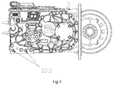
- the integrated transmission gearbox 1 is provided with a mounting flange plate 101 connected to a drive axle housing of the forklift, and a first bolt hole 102 and a second bolt hole 103, as two means for assisting in mounting and fixing, connected to a forklift body.
- One of the first bolt hole 102 and the second bolt hole 103, as two means for assisting in mounting and fixing, connected to the forklift body, may be selected according to an actual mounting state of the forklift, improving mounting adaptability of the integrative power system.
- a control method for a liquid-cooled integrative power system for electric forklift includes the following steps.
- a vehicle controller 2 receives a drive demand signal 300, a hydraulic operation demand signal 301, a status of battery pack management system and request signal 302, and other information from the forklift.
- the drive demand signal 300 includes an accelerator pedal signal, a brake pedal signal, a gear switch signal and other information.
- the hydraulic operation demand signal 301 includes a lift potentiometer signal, a tilt switch signal, a related equipment signal and other information.
- the status of battery pack management system and request signal 302 includes battery state information, temperature information, current and voltage information, discharge rate permission information, and other bus information for a battery pack.
- step 2 the vehicle controller 2 processes the drive demand signal 300, the hydraulic operation demand signal 301, the status of battery pack management system and request signal 302, and other information from the forklift, preferentially processes the information about the drive demand signal 300 and the hydraulic operation demand signal 301 received from the forklift according to the status of battery pack management system and request signal 302 and other information, and supplies required power to a drive and hydraulic power system on demand and quantity; and the vehicle controller 2 outputs a drive control instruction and a hydraulic control instruction respectively to the integrated motor controller 13 through a low-voltage power supply and a control wire harness according to operating and working states of the forklift, and then performs a coordinated control on a drive motor controller and a oil pump motor controller for current output.
- the drive motor controller controls the drive motor 9 through a high-voltage connection and a low-voltage connection between the drive motor 9 and the drive motor controller arranged inside a housing of the integrated motor controller 13;
- the oil pump motor controller controls the oil pump motor 6 through a high-voltage connection and a low-voltage connection between the oil pump motor 6 and the oil pump motor controller arranged inside the housing of the integrated motor controller 13;
- power of the drive motor 9 is outputted externally through the drive motor transmission mechanism 1000, as drive power;
- power of the oil pump motor 6 is outputted to the oil pump 11 through the oil pump motor transmission mechanism 1100, and the oil pump 11 outputs a high-pressure oil source to a hydraulic operating system; and thus drive operation and hydraulic steering of the electric forklift and work actions of the electric forklift executed based on hydraulic transmission are finally realized.
- the power system of the electric forklift may be highly integrated, compactly arranged, and completely integrated into a unified whole structure without distributed arrangement, have a simple structure, and facilitate the assembly of the vehicle, which greatly improves the integration and reliability of the power system.
- the external connecting cables between the motor and the motor controller are completely eliminated, the length of the cables is significantly reduced to reduce resistance caused by the excessive length of the cable and improve operation efficiency of the power system while reducing assembly and mounting procedures, and at the same time, the external connecting cables are eliminated to improve insulation safety and electrical safety performance of the vehicle and prolong the safety operation time of the electric forklift.
- a liquid cooling form of an integrated series water channel is set to perform forced liquid cooling for the motor and the motor controller, which greatly reduces temperature rise of the electric forklift drive and hydraulic integrative power system, improves the reliability of the integrative power system, prolongs the service life, and meets more stringent requirements of the electric forklift.
Landscapes
- Engineering & Computer Science (AREA)
- Transportation (AREA)
- Mechanical Engineering (AREA)
- Structural Engineering (AREA)
- Chemical & Material Sciences (AREA)
- Combustion & Propulsion (AREA)
- Power Engineering (AREA)
- Life Sciences & Earth Sciences (AREA)
- Civil Engineering (AREA)
- Geology (AREA)
- General Engineering & Computer Science (AREA)
- Microelectronics & Electronic Packaging (AREA)
- Physics & Mathematics (AREA)
- Thermal Sciences (AREA)
- Fluid Mechanics (AREA)
- Sustainable Development (AREA)
- Sustainable Energy (AREA)
- Forklifts And Lifting Vehicles (AREA)
- Arrangement Of Transmissions (AREA)
- Motor Power Transmission Devices (AREA)
- Arrangement Or Mounting Of Propulsion Units For Vehicles (AREA)
- Electric Propulsion And Braking For Vehicles (AREA)
Abstract
Description
- The present invention relates to the field of electric industrial vehicle technologies, and in particular, to a liquid-cooled integrative power system for electric forklift and a control method thereof.
- The industrial vehicle market in China has a broad development space. In particular, an electric forklift market has great potential. With the continuous development of economy, higher requirements are put forward for an electric forklift drive and hydraulic power system.
- The existing electric forklift drive and hydraulic power system has a single technical route, in which a walking power unit basically consists of a drive motor and a front axle reducer, a hydraulic power unit consists of an oil pump motor and an oil pump, and a motor control unit consists of a drive motor controller and an oil pump motor controller arranged separately. The whole power system adopts wide-range distributed arrangement, in which the walking power unit is arranged at a front axle of a vehicle body, the hydraulic power unit is arranged in the middle or at the rear of the vehicle body, and the motor control unit is arranged in the middle or at the rear of the vehicle body. In such a system, both the walking power unit and the hydraulic power unit are far away from the motor control unit, and thus the connecting cables are too long, which is not conducive to the assembly of the whole vehicle. Moreover, an excessive length of the cable may increase costs, affect power efficiency, and eventually lead to a significant increase in energy consumption of the vehicle. The drive and hydraulic power system with wide-range distributed arrangement is heat-dissipated complexly and inefficiently, each unit is required to be separately cooled or heat-dissipated, and most are heat-dissipated by natural conduction or forced wind-cooling, resulting in a complex structure, a poor heat-dissipation effect and a significant increase in cost.
- Thus, an integrative power system, with a highly integrated structure and capable of realizing integrated arrangement and efficient heat-dissipation, is needed for the electric forklift drive and hydraulic power system, so as to reduce system costs and improve system efficiency.
- In order to overcome the above technical problems, an objective of the present invention is to provide a liquid-cooled integrative power system for electric forklift and a control method thereof.
- The objective of the present invention may be achieved through the following technical solutions.
- A liquid-cooled integrative power system for electric forklift, including an integrated transmission gearbox, a drive motor, an oil pump motor, an integrated motor controller, an oil pump and a vehicle controller; the integrated transmission gearbox including a drive motor transmission mechanism and an oil pump motor transmission mechanism; wherein the drive motor transmission mechanism is arranged inside the integrated transmission gearbox, the drive motor transmission mechanism including a plurality of sets of gear shafts arranged in parallel, mating gears on each set of gear shafts engaging with each other, an input gear shaft of the first-stage being provided with a first spline, an output gear shaft of the last-stage being provided with a differential, and each of the gear shafts of the drive motor transmission mechanism being arranged on a housing of the integrated transmission gearbox through a bearing; and wherein the oil pump motor transmission mechanism is arranged inside the integrated transmission gearbox, the oil pump motor transmission mechanism including a plurality of sets of gear shafts arranged in parallel, mating gears on each set of gear shafts engaging with each other, a first input gear shaft and an output gear shaft of the last-stage being respectively provided with a second spline and a third spline, and each of the gear shafts of the oil pump motor transmission mechanism being arranged on the housing of the integrated transmission gearbox through a bearing;
- the drive motor being fixed to a lateral side of the integrated transmission gearbox through a mounting bolt on a rear cover of the motor, and an output shaft of the drive motor being connected, through a spline, to the first spline on the input gear shaft of the first-stage on the drive motor transmission mechanism;
- the oil pump motor being fixed to a lateral side of the integrated transmission gearbox through a mounting bolt on a rear cover of the motor, and an output shaft of the oil pump motor being connected, through a spline, to the second spline on the input gear shaft of the first-stage on the oil pump motor transmission mechanism;
- the integrated motor controller being fixedly mounted to an upper side of the drive motor, the oil pump motor and the integrated transmission gearbox;
- the oil pump being fixedly mounted to a lateral side of the integrated transmission gearbox, and an input shaft of the oil pump being connected to, through a spline, the third spline on the output gear shaft of the last-stage on the oil pump motor transmission mechanism;
- the vehicle controller being fixedly mounted to an upper cover of the integrated motor controller, and the vehicle controller being electrically connected to the integrated motor controller by wire harness; and the vehicle controller performing a coordinated control on the integrative power system by receiving operation signals and power battery pack states and request signals of the forklift, a specific control method including the following steps:
- step 1: receiving, with the vehicle controller, a drive demand signal, a hydraulic operation demand signal, a status of battery pack management system and request signal, and other information from the forklift; the drive demand signal including an accelerator pedal signal, a brake pedal signal, a gear switch signal and other information; the hydraulic operation demand signal including a lift potentiometer signal, a tilt switch signal, a related equipment signal and other information; the status of battery pack management system and request signal including battery state information, temperature information, current and voltage information, discharge rate permission information, and other bus information for a battery pack;
- step 2: processing, with the vehicle controller, the drive demand signal, the hydraulic operation demand signal, the status of battery pack management system and request signal, and other information from the forklift, preferentially processing the information about the drive demand signal and the hydraulic operation demand signal received from the forklift according to the status of battery pack management system and request signal and other information, and supplying required power to a drive and hydraulic power system on demand and quantity; outputting, with the vehicle controller, a drive control instruction and a hydraulic control instruction respectively to the integrated motor controller through a low-voltage power supply and a control wire harness according to operating and working states of the forklift, and then performing a coordinated control on a drive motor controller and an oil pump motor controller for current output; and
- step 3: controlling, with the drive motor controller, the drive motor through a high-voltage connection and a low-voltage connection between the drive motor and the drive motor controller arranged inside a housing of the integrated motor controller; controlling, with the oil pump motor controller, the oil pump motor through a high-voltage connection and a low-voltage connection between the oil pump motor and the oil pump motor controller arranged inside the housing of the integrated motor controller; outputting externally power of the drive motor, as drive power, through the drive motor transmission mechanism, outputting power of the oil pump motor to the oil pump through the oil pump motor transmission mechanism, and outputting, with the oil pump, a high-pressure oil source to a hydraulic operating system; and finally, realizing drive operation and hydraulic steering of the electric forklift and work actions of the electric forklift executed based on hydraulic transmission.
- As a further solution of the present invention, the integrated motor controller includes the drive motor controller and the oil pump motor controller; a three-phase terminal of the drive motor controller and a three-phase terminal on the rear cover of the drive motor are directly connected inside the housing of the integrated motor controller through a copper bar; a low-voltage signal terminal of the drive motor controller and a low-voltage signal terminal on the rear cover of the drive motor are directly connected inside the housing of the integrated motor controller through a mating plug-in connector; a three-phase terminal of the oil pump motor controller and a three-phase terminal on the rear cover of the oil pump motor are directly connected inside the housing of the integrated motor controller through a copper bar; and a low-voltage signal terminal of the oil pump motor controller and a low-voltage signal terminal on the rear cover of the oil pump motor are directly connected inside the housing of the integrated motor controller through a mating plug-in connector.
- As a further solution of the present invention, a first heat-dissipation water channel is arranged inside a housing of the drive motor, and a first water inlet and a first water outlet of the first heat-dissipation water channel are arranged on the rear cover of the drive motor; a second heat-dissipation water channel is arranged inside a housing of the oil pump motor, a second water outlet of the second heat-dissipation water channel is arranged on the rear cover of the motor, and a second water inlet of the second heat-dissipation water channel is arranged on a front cover of the motor; a third heat-dissipation water channel is arranged at the bottom of the integrated motor controller, and a third water inlet and a third water outlet of the third heat-dissipation water channel are arranged on one side of the integrated motor controller; the third water outlet on one side of the integrated motor controller and the second water inlet on the front cover of the oil pump motor are connected through a first heat-dissipation pipeline, and the second water outlet on the rear cover of the oil pump motor and the first water inlet on the rear cover of the drive motor are connected through a second heat-dissipation pipeline; the third water inlet on one side of the integrated motor controller and a water outlet of an external cooling system are connected through a third heat-dissipation pipeline; and the first water outlet on the rear cover of the drive motor and a water inlet of the external cooling system are connected through a fourth heat-dissipation pipeline.
- As a further solution of the present invention, the drive motor transmission mechanism includes a first input shaft, a second shaft, a third shaft and a first output shaft arranged in parallel; the first input shaft, the second shaft, the third shaft and the first output shaft are all fixedly mounted on the housing of the integrated transmission gearbox through bearings; the first input shaft is fixedly connected with an input shaft gear, the second shaft is fixedly connected with a first-stage reduction driven gear and a second-stage reduction driving gear, the third shaft is fixedly connected with a second-stage reduction driven gear and a third-stage reduction driving gear, and the first output shaft is fixedly connected with a third-stage reduction driven gear; the input shaft gear engages the first-stage reduction driven gear in a transmission manner, the second-stage reduction driving gear engages the second-stage reduction driven gear in a transmission manner, and the third-stage reduction driving gear engages the third-stage reduction driven gear in a transmission manner; the first input gear shaft is provided with the first spline, and the first output shaft is provided with the differential.
- As a further solution of the present invention, the oil pump motor transmission mechanism includes a second input shaft and a second output shaft arranged in parallel; the second input shaft and the second output shaft are both fixedly mounted on the housing of the integrated transmission gearbox through bearings; the second input shaft is fixedly connected with an input shaft gear, and the second output shaft is fixedly connected with an output shaft gear; the input shaft gear engages the output shaft gear in a transmission manner; and the second input shaft and the second output shaft are respectively provided with the second spline and the third spline.
- As a further solution of the present invention, the integrated motor controller is provided with a DC high-voltage positive and negative pole plug-in connector, and a signal plug-in connector of a low-voltage control signal; an upper cover of the integrated motor controller is provided with an overhaul and disassembly cover plate, and a cover-open switch is arranged below the overhaul and disassembly cover plate.
- As a further solution of the present invention, the integrated transmission gearbox is provided with a mounting flange plate connected to a drive axle housing of the forklift, and a first bolt hole and a second bolt hole, as two means for assisting in mounting and fixing, connected to a forklift body.
- As a further solution of the present invention, a control method for a liquid-cooled integrative power system for electric forklift, including the following steps:
- step 1: receiving, with a vehicle controller, a drive demand signal, a hydraulic operation demand signal, a status of battery pack management system and request signal, and other information from the forklift; the drive demand signal including an accelerator pedal signal, a brake pedal signal, a gear switch signal and other information; the hydraulic operation demand signal including a lift potentiometer signal, a tilt switch signal, a related equipment signal and other information; the status of battery pack management system and request signal including battery state information, temperature information, current and voltage information, discharge rate permission information, and other bus information for a battery pack;
- step 2: processing, with the vehicle controller, the drive demand signal, the hydraulic operation demand signal, the status of battery pack management system and request signal, and other information from the forklift, preferentially processing the information about the drive demand signal and the hydraulic operation demand signal received from the forklift according to the status of battery pack management system and request signal and other information, and supplying required power to a drive and hydraulic power system on demand and quantity; outputting, with the vehicle controller, a drive control instruction and a hydraulic control instruction respectively to an integrated motor controller through a low-voltage power supply and a control wire harness according to operating and working states of the forklift, and then performing a coordinated control on a drive motor controller and an oil pump motor controller for current output; and
- step 3: controlling, with the drive motor controller, a drive motor through a high-voltage connection and a low-voltage connection between the drive motor and the drive motor controller arranged inside a housing of the integrated motor controller; controlling, with the oil pump motor controller, an oil pump motor through a high-voltage connection and a low-voltage connection between the oil pump motor and the oil pump motor controller arranged inside the housing of the integrated motor controller; outputting externally power of the drive motor, as drive power, through the drive motor transmission mechanism, outputting power of the oil pump motor to the oil pump through the oil pump motor transmission mechanism, and outputting, with the oil pump, a high-pressure oil source to a hydraulic operating system; and finally, realizing drive operation and hydraulic steering of the electric forklift and work actions of the electric forklift executed based on hydraulic transmission.
- The present invention has the following beneficial effects.
- According to the present invention, the power system of the electric forklift may be highly integrated, compactly arranged, and completely integrated into a unified whole structure without distributed arrangement, have a simple structure, and facilitate the assembly of the vehicle, which greatly improves the integration and reliability of the power system.
- According to the present invention, in an electric forklift drive and hydraulic integrative power system, the external connecting cables between the motor and the motor controller are completely eliminated, with the length of the cables being significantly reduced, so as to reduce resistance caused by the excessive length of the cable and improve operation efficiency of the power system while reducing assembly and mounting procedures. And at the same time, the external connecting cables are eliminated to improve insulation safety and electrical safety performance of the vehicle and prolong the safety operation period of the electric forklift.
- According to the present invention, a liquid cooling form of an integrated series water channel is set to perform forced liquid cooling for the motor and the motor controller, which greatly reduces temperature rise of the electric forklift drive and hydraulic integrative power system, improves the reliability of the integrative power system, prolongs the service life, and meets more stringent requirements of the electric forklift.
- The present invention is further described below with reference to the accompanying drawings.
-
FIG. 1 shows an overall structure of a liquid-cooled integrative power system for electric forklift according to the present invention; -
FIG. 2 is an overall schematic diagram of the liquid-cooled integrative power system for electric forklift according to the present invention; -
FIG. 3 is an overall bottom view of the liquid-cooled integrative power system for electric forklift according to the present invention; -
FIG. 4 is an overall side view of the liquid-cooled integrative power system for electric forklift according to the present invention; -
FIG. 5 is a schematic structural diagram of an integrated transmission gearbox according to the present invention; -
FIG. 6 is a schematic structural diagram of a drive motor transmission mechanism according to the present invention; -
FIG. 7 is a schematic structural diagram of an oil pump motor transmission mechanism according to the present invention; and -
FIG. 8 is a schematic diagram of control execution according to the present invention. - The technical solutions according to the embodiments of the present invention will be described clearly and completely below with reference to the accompanying drawings in the embodiments of the present invention. Apparently, the described embodiments are merely some of rather than all of the embodiments of the present invention. All other embodiments acquired by those skilled in the art without creative efforts based on the embodiments of the present invention shall fall within the protection scope of the present application.
- Referring to
FIG. 1 to FIG. 8 , a liquid-cooled integrative power system for electric forklift and a control method thereof are shown, including an integratedtransmission gearbox 1, adrive motor 9, anoil pump motor 6, an integratedmotor controller 13, anoil pump 11 and avehicle controller 2. - The integrated
transmission gearbox 1 includes a drivemotor transmission mechanism 1000 and an oil pumpmotor transmission mechanism 1100. The drivemotor transmission mechanism 1000 is arranged inside the integratedtransmission gearbox 1. The drivemotor transmission mechanism 1000 includes a plurality of sets of gear shafts arranged in parallel, mating gears on each set of gear shafts engage with each other, a firstinput gear shaft 1003 of the first-stage is provided with afirst spline 1001, anoutput gear shaft 1009 of the last-stage is provided with a differential 1008, and each gear shaft of the drivemotor transmission mechanism 1000 is arranged on a housing 1110 of the integratedtransmission gearbox 1 through a bearing. The oil pumpmotor transmission mechanism 1100 is arranged inside the integratedtransmission gearbox 1. The oil pumpmotor transmission mechanism 1100 includes a plurality of sets of gear shafts arranged in parallel, mating gears on each set of gear shafts engage with each other, a secondinput gear shaft 1103 of the first-stage and a secondoutput gear shaft 1104 of the last-stage are respectively provided with asecond spline 1101 and athird spline 1105, and each gear shaft of the oil pumpmotor transmission mechanism 1100 is arranged on the housing 1110 of the integratedtransmission gearbox 1 through a bearing. - The
drive motor 9 is fixed to a lateral side of the integratedtransmission gearbox 1 through a mounting bolt on a rear cover of the motor, and an output shaft of thedrive motor 9 is connected, through a spline, to thefirst spline 1001 on the firstinput gear shaft 1003 of the first-stage on the drivemotor transmission mechanism 1000. - The
oil pump motor 6 is fixed to a lateral side of the integratedtransmission gearbox 1 through a mounting bolt on a rear cover of the motor, and an output shaft of theoil pump motor 6 is connected, through a spline, to thesecond spline 1101 on the secondinput gear shaft 1103 of the first-stage on the oil pumpmotor transmission mechanism 1100. - The integrated
motor controller 13 is fixedly mounted to an upper side of thedrive motor 9, theoil pump motor 6 and the integratedtransmission gearbox 1. - The
oil pump 11 is fixedly mounted to a lateral side of the integratedtransmission gearbox 1, and an input shaft of theoil pump 11 is connected, through a spline, to thethird spline 1105 on the secondoutput gear shaft 1104 of the last-stage on the oil pumpmotor transmission mechanism 1100. - The
vehicle controller 2 is fixedly mounted to an upper cover of the integratedmotor controller 13, and thevehicle controller 2 is electrically connected to the integratedmotor controller 13 by wire harness. Thevehicle controller 2 performs a coordinated control on the integrative power system by receiving operation signals and power battery pack states and request signals of the forklift. A specific control method includes the following steps. - In
step 1, avehicle controller 2 receives adrive demand signal 300, a hydraulicoperation demand signal 301, a status of battery pack management system andrequest signal 302, and other information from the forklift. Thedrive demand signal 300 includes an accelerator pedal signal, a brake pedal signal, a gear switch signal and other information. The hydraulicoperation demand signal 301 includes a lift potentiometer signal, a tilt switch signal, a related equipment signal and other information. The status of battery pack management system andrequest signal 302 includes battery state information, temperature information, current and voltage information, discharge rate permission information, and other bus information for a battery pack. - In
step 2, thevehicle controller 2 processes thedrive demand signal 300, the hydraulicoperation demand signal 301, the status of battery pack management system andrequest signal 302, and other information from the forklift, preferentially processes the information about thedrive demand signal 300 and the hydraulicoperation demand signal 301 received from the forklift according to the status of battery pack management system andrequest signal 302 and other information, and supplies required power to a drive and hydraulic power system on demand and quantity; and thevehicle controller 2 outputs a drive control instruction and a hydraulic control instruction respectively to theintegrated motor controller 13 through a low-voltage power supply and a control wire harness according to operating and working states of the forklift, and then performs a coordinated control on a drive motor controller and an oil pump motor controller for current output. - In
step 3, the drive motor controller controls thedrive motor 9 through a high-voltage connection and a low-voltage connection between thedrive motor 9 and the drive motor controller arranged inside a housing of theintegrated motor controller 13; the oil pump motor controller controls theoil pump motor 6 through a high-voltage connection and a low-voltage connection between theoil pump motor 6 and the oil pump motor controller arranged inside the housing of theintegrated motor controller 13; power of thedrive motor 9 is outputted externally through the drivemotor transmission mechanism 1000, as drive power; power of theoil pump motor 6 is outputted to theoil pump 11 through the oil pumpmotor transmission mechanism 1100, and theoil pump 11 outputs a high-pressure oil source to a hydraulic operating system; and thus drive operation and hydraulic steering of the electric forklift and work actions of the electric forklift executed based on hydraulic transmission are finally realized. - The
integrated motor controller 13 includes the drive motor controller 91 and the oilpump motor controller 61. A three-phase terminal of the drive motor controller 91 and a three-phase terminal on the rear cover of thedrive motor 9 are directly connected inside the housing of theintegrated motor controller 13 through a copper bar. A low-voltage signal terminal of the drive motor controller 91 and a low-voltage signal terminal on the rear cover of thedrive motor 9 are directly connected inside the housing of theintegrated motor controller 13 through a mating plug-in connector. A three-phase terminal of the oilpump motor controller 61 and a three-phase terminal on the rear cover of theoil pump motor 6 are directly connected inside the housing of theintegrated motor controller 13 through a copper bar. A low-voltage signal terminal of the oilpump motor controller 61 and a low-voltage signal terminal on the rear cover of theoil pump motor 6 are directly connected inside the housing of theintegrated motor controller 13 through a mating plug-in connector. - A first heat-dissipation water channel is arranged inside a housing of the
drive motor 9, and a first water inlet 80 and a first water outlet 8 of the first heat-dissipation water channel are arranged on the rear cover of thedrive motor 9. A second heat-dissipation water channel is arranged inside a housing of theoil pump motor 6, a second water outlet 60 of the second heat-dissipation water channel is arranged on the rear cover of themotor 6, and asecond water inlet 61 of the second heat-dissipation water channel is arranged on a front cover of themotor 6. A third heat-dissipation water channel is arranged at the bottom of theintegrated motor controller 13, and athird water inlet 12 and athird water outlet 120 of the third heat-dissipation water channel are arranged on one side of theintegrated motor controller 13. Thethird water outlet 120 on one side of theintegrated motor controller 13 and thesecond water inlet 61 on the front cover of theoil pump motor 6 are connected through a first heat-dissipation pipeline 5, and the second water outlet 60 on the rear cover of theoil pump motor 6 and the first water inlet 80 on the rear cover of thedrive motor 9 are connected through a second heat-dissipation pipeline 7. Thethird water inlet 12 on one side of theintegrated motor controller 13 and a water outlet of an external cooling system are connected through a third heat-dissipation pipeline. The first water outlet 8 on the rear cover of thedrive motor 9 and a water inlet of the external cooling system are connected through a fourth heat-dissipation pipeline. In this way, circulation of series heat-dissipation water channels for the motor and the motor controller is formed. - The drive
motor transmission mechanism 1000 includes the firstinput gear shaft 1003, asecond shaft 1005, athird shaft 1006 and a first output shaft arranged in parallel. The firstinput gear shaft 1003, thesecond shaft 1005, thethird shaft 1006 and the first output shaft are all fixedly mounted on the housing 1110 of theintegrated transmission gearbox 1 through bearings. The firstinput gear shaft 1003 is fixedly connected with ainput shaft gear 1002, thesecond shaft 1005 is fixedly connected with a first-stage reduction drivengear 1004 and a second-stagereduction driving gear 1011, thethird shaft 1006 is fixedly connected with a second-stage reduction drivengear 1007 and a third-stagereduction driving gear 1010, and the first output shaft is fixedly connected with a third-stage reduction drivengear 1106. Theinput shaft gear 1002 engages with the first-stage reduction drivengear 1004 in a transmission manner, the second-stagereduction driving gear 1011 engages with the second-stage reduction drivengear 1007 in a transmission manner, and the third-stagereduction driving gear 1010 engages with the third-stage reduction drivengear 1106 in a transmission manner. The firstinput gear shaft 1003 is provided with thefirst spline 1001, and the first output shaft is provided with the differential 1008. The oil pumpmotor transmission mechanism 1100 includes the secondinput gear shaft 1103 and the secondoutput gear shaft 1104 arranged in parallel. The secondinput gear shaft 1103 and the secondoutput gear shaft 1104 are both fixedly mounted on the housing 1110 of theintegrated transmission gearbox 1 through bearings. The secondinput gear shaft 1103 is fixedly connected with aninput shaft gear 1102, and the secondoutput gear shaft 1104 is fixedly connected with anoutput shaft gear 1106. Theinput shaft gear 1102 engages with theoutput shaft gear 1106 in a transmission manner. The secondinput gear shaft 1103 and the secondoutput gear shaft 1104 are respectively provided with thesecond spline 1101 and thethird spline 1105. The first input-shaft spline 1001 of the drivemotor transmission mechanism 1000 and the second input-shaft spline 1101 of the oil pumpmotor transmission mechanism 1100 serve as power input interfaces of theintegrated transmission gearbox 1. The differential 1008 on the output shaft of the drivemotor transmission mechanism 1000 serves as a drive power output interface of theintegrated transmission gearbox 1. The third output-shaft spline 1105 of the oil pumpmotor transmission mechanism 1100 serves as a hydraulic power output interface of theintegrated transmission gearbox 1. - The
integrated motor controller 13 is provided with a DC high-voltage positive and negative pole plug-inconnector 3 and a signal plug-inconnector 4 of a low-voltage control signal. An upper cover of theintegrated motor controller 13 is provided with an overhaul anddisassembly cover plate 10, and a cover-open switch is arranged below the overhaul anddisassembly cover plate 10. After the overhaul anddisassembly cover plate 10 is opened, theintegrated motor controller 13 can be separated from thedrive motor 9 and theoil pump motor 6 by simply removing a three-phase harness connecting bolt and a low-voltage control harness connector, which facilitates disassembly. At the same time, with the cover-open switch arranged below the overhaul anddisassembly cover plate 10, a high voltage of the system can be cut off during live operation, to ensure electrical safety during the operation. - The
integrated transmission gearbox 1 is provided with a mountingflange plate 101 connected to a drive axle housing of the forklift, and afirst bolt hole 102 and asecond bolt hole 103, as two means for assisting in mounting and fixing, connected to a forklift body. One of thefirst bolt hole 102 and thesecond bolt hole 103, as two means for assisting in mounting and fixing, connected to the forklift body, may be selected according to an actual mounting state of the forklift, improving mounting adaptability of the integrative power system. - A control method for a liquid-cooled integrative power system for electric forklift includes the following steps.
- In
step 1, avehicle controller 2 receives adrive demand signal 300, a hydraulicoperation demand signal 301, a status of battery pack management system andrequest signal 302, and other information from the forklift. Thedrive demand signal 300 includes an accelerator pedal signal, a brake pedal signal, a gear switch signal and other information. The hydraulicoperation demand signal 301 includes a lift potentiometer signal, a tilt switch signal, a related equipment signal and other information. The status of battery pack management system andrequest signal 302 includes battery state information, temperature information, current and voltage information, discharge rate permission information, and other bus information for a battery pack. - In
step 2, thevehicle controller 2 processes thedrive demand signal 300, the hydraulicoperation demand signal 301, the status of battery pack management system andrequest signal 302, and other information from the forklift, preferentially processes the information about thedrive demand signal 300 and the hydraulicoperation demand signal 301 received from the forklift according to the status of battery pack management system andrequest signal 302 and other information, and supplies required power to a drive and hydraulic power system on demand and quantity; and thevehicle controller 2 outputs a drive control instruction and a hydraulic control instruction respectively to theintegrated motor controller 13 through a low-voltage power supply and a control wire harness according to operating and working states of the forklift, and then performs a coordinated control on a drive motor controller and a oil pump motor controller for current output. - In
step 3, the drive motor controller controls thedrive motor 9 through a high-voltage connection and a low-voltage connection between thedrive motor 9 and the drive motor controller arranged inside a housing of theintegrated motor controller 13; the oil pump motor controller controls theoil pump motor 6 through a high-voltage connection and a low-voltage connection between theoil pump motor 6 and the oil pump motor controller arranged inside the housing of theintegrated motor controller 13; power of thedrive motor 9 is outputted externally through the drivemotor transmission mechanism 1000, as drive power; power of theoil pump motor 6 is outputted to theoil pump 11 through the oil pumpmotor transmission mechanism 1100, and theoil pump 11 outputs a high-pressure oil source to a hydraulic operating system; and thus drive operation and hydraulic steering of the electric forklift and work actions of the electric forklift executed based on hydraulic transmission are finally realized. - The working principle of the present invention is as follows. According to the present invention, the power system of the electric forklift may be highly integrated, compactly arranged, and completely integrated into a unified whole structure without distributed arrangement, have a simple structure, and facilitate the assembly of the vehicle, which greatly improves the integration and reliability of the power system. At the same time, according to the present invention, in an electric forklift drive and hydraulic integrative power system, the external connecting cables between the motor and the motor controller are completely eliminated, the length of the cables is significantly reduced to reduce resistance caused by the excessive length of the cable and improve operation efficiency of the power system while reducing assembly and mounting procedures, and at the same time, the external connecting cables are eliminated to improve insulation safety and electrical safety performance of the vehicle and prolong the safety operation time of the electric forklift. In addition, according to the present invention, a liquid cooling form of an integrated series water channel is set to perform forced liquid cooling for the motor and the motor controller, which greatly reduces temperature rise of the electric forklift drive and hydraulic integrative power system, improves the reliability of the integrative power system, prolongs the service life, and meets more stringent requirements of the electric forklift.
- In the description of the present specification, reference throughout this specification to "an embodiment", "example", "specific example" and the like means that a particular feature, structure, material, or characteristic described in connection with the embodiment or example is included in at least one embodiment or example of the present invention. In the specification, the schematic expressions to the above-mentioned terms are not necessarily referring to the same embodiment or example. Furthermore, the described particular features, structures, materials, or characteristics may be combined in any suitable manner in one or more embodiments or examples.
- The above contents are only examples and illustrations of the present invention. Various modifications, supplements or alternatives in a similar way may be made to the particularly described embodiments by those skilled in the art, which may fall within the protection scope of the present application provided that such modifications, supplements or alternatives do not depart from the present invention and go beyond the scope defined in the appended claims.
Claims (8)
- A liquid-cooled integrative power system for electric forklift, characterized in that it comprises an integrated transmission gearbox (1), a drive motor (9), an oil pump motor (6), an integrated motor controller (13), an oil pump (11) and a vehicle controller (2);the integrated transmission gearbox (1) comprising a drive motor transmission mechanism (1000) and an oil pump motor transmission mechanism (1100); the drive motor transmission mechanism (1000) being arranged inside the integrated transmission gearbox (1), the drive motor transmission mechanism (1000) comprising a plurality of sets of gear shafts arranged in parallel, mating gears on each set of gear shafts engaging with each other, a first input gear shaft (1003) being provided with a first spline (1001), a second output gear shaft (1009) being provided with a differential (1008), and each of the gear shafts of the drive motor transmission mechanism (1000) being arranged on a housing (1110) of the integrated transmission gearbox (1) through a bearing; the oil pump motor transmission mechanism (1100) being arranged inside the integrated transmission gearbox (1), the oil pump motor transmission mechanism (1100) comprising a plurality of sets of gear shafts arranged in parallel, mating gears on each set of gear shafts engaging with each other, a second input gear shaft (1103) and a second output gear shaft (1104) being respectively provided with a second spline (1101) and a third spline (1105), and each gear shaft of the oil pump motor transmission mechanism (1100) being arranged on the housing (1110) of the integrated transmission gearbox (1) through a bearing;the drive motor (9) being fixed to a lateral side of the integrated transmission gearbox (1) through a mounting bolt on a rear cover of the motor, and an output shaft of the drive motor (9) being connected, through a spline, to the first spline (1001) on the first input gear shaft (1003) on the drive motor transmission mechanism (1000);the oil pump motor (6) being fixed to a lateral side of the integrated transmission gearbox (1) through a mounting bolt on a rear cover of the motor, and an output shaft of the oil pump motor (6) being connected, through a spline, to the second spline (1101) on the second input gear shaft (1103) on the oil pump motor transmission mechanism (1100);the integrated motor controller (13) being fixedly mounted to an upper side of the drive motor (9), the oil pump motor (6) and the integrated transmission gearbox (1);the oil pump (11) being fixedly mounted to a lateral side of the integrated transmission gearbox (1), and an input shaft of the oil pump (11) being connected, through a spline, to the third spline (1105) on the second output gear shaft (1104) on the oil pump motor transmission mechanism (1100); andthe vehicle controller (2) being fixedly mounted to an upper cover of the integrated motor controller (13), and the vehicle controller (2) being electrically connected to the integrated motor controller (13) by wire harness; and the vehicle controller (2) performing a coordinated control on the integrative power system by receiving operation signals and power battery pack states and request signals of the forklift, a specific control method comprising the following steps:step 1: receiving, with the vehicle controller (2), a drive demand signal (300), a hydraulic operation demand signal (301), a status of battery pack management system and request signal (302), and other information from the forklift; the drive demand signal (300) comprising an accelerator pedal signal, a brake pedal signal, a gear switch signal and other information; the hydraulic operation demand signal (301) comprising a lift potentiometer signal, a tilt switch signal, a related equipment signal and other information; the status of battery pack management system and request signal (302) comprising battery state information, temperature information, current and voltage information, discharge rate permission information, and other bus information for a battery pack;step 2: processing, with the vehicle controller (2), the drive demand signal (300), the hydraulic operation demand signal (301), the status of battery pack management system and request signal (302), and other information from the forklift, preferentially processing the information about the drive demand signal (300) and the hydraulic operation demand signal (301) received from the forklift according to the status of battery pack management system and request signal (302) and other information, and supplying required power to a drive and hydraulic power system on demand and quantity; outputting, with the vehicle controller (2), a drive control instruction and a hydraulic control instruction respectively to the integrated motor controller (13) through a low-voltage power supply and a control wire harness according to operating and working states of the forklift, and then performing a coordinated control on a drive motor controller and an oil pump motor controller for current output; andstep 3: controlling, with the drive motor controller, the drive motor (9) through a high-voltage connection and a low-voltage connection between the drive motor (9) and the drive motor controller arranged inside a housing of the integrated motor controller (13); controlling, with the oil pump motor controller, the oil pump motor (6) through a high-voltage connection and a low-voltage connection between the oil pump motor (6) and the oil pump motor controller arranged inside the housing of the integrated motor controller (13); outputting externally power of the drive motor (9), as drive power, through the drive motor transmission mechanism (1000), outputting power of the oil pump motor (6) to the oil pump (11) through the oil pump motor transmission mechanism (1100), and outputting, with the oil pump (11), a high-pressure oil source to a hydraulic operating system; and finally, realizing drive operation and hydraulic steering of the electric forklift and work actions of the electric forklift executed based on hydraulic transmission.
- The liquid-cooled integrative power system for electric forklift according to claim 1, characterized in that the integrated motor controller (13) comprises the drive motor controller (91) and the oil pump motor controller (61); a three-phase terminal of the drive motor controller (91) and a three-phase terminal on the rear cover of the drive motor (9) are directly connected inside the housing of the integrated motor controller (13) through a copper bar; a low-voltage signal terminal of the drive motor controller (91) and a low-voltage signal terminal on the rear cover of the drive motor (9) are directly connected inside the housing of the integrated motor controller (13) through a mating plug-in connector; a three-phase terminal of the oil pump motor controller (61) and a three-phase terminal on the rear cover of the oil pump motor (6) are directly connected inside the housing of the integrated motor controller (13) through a copper bar; and a low-voltage signal terminal of the oil pump motor controller (61) and a low-voltage signal terminal on the rear cover of the oil pump motor (6) are directly connected inside the housing of the integrated motor controller (13) through a mating plug-in connector.
- The liquid-cooled integrative power system for electric forklift according to claim 1, characterized in that a first heat-dissipation water channel is arranged inside a housing of the drive motor (9), and a first water inlet (80) and a first water outlet (8) of the first heat-dissipation water channel are arranged on the rear cover of the drive motor (9); a second heat-dissipation water channel is arranged inside a housing of the oil pump motor (6), a second water outlet (60) of the second heat-dissipation water channel is arranged on the rear cover of the motor (6), and a second water inlet (61) of the second heat-dissipation water channel is arranged on a front cover of the motor (6); a third heat-dissipation water channel is arranged at the bottom of the integrated motor controller (13), and a third water inlet (12) and a third water outlet (120) of the third heat-dissipation water channel are arranged on one side of the integrated motor controller (13); the third water outlet (120) on one side of the integrated motor controller (13) and the second water inlet (61) on the front cover of the oil pump motor (6) are connected through a first heat-dissipation pipeline (5), and the second water outlet (60) on the rear cover of the oil pump motor (6) and the first water inlet (80) on the rear cover of the drive motor (9) are connected through a second heat-dissipation pipeline (7); the third water inlet (12) on one side of the integrated motor controller (13) and a water outlet of an external cooling system are connected through a third heat-dissipation pipeline; and the first water outlet (8) on the rear cover of the drive motor (9) and a water inlet of the external cooling system are connected through a fourth heat-dissipation pipeline.
- The liquid-cooled integrative power system for electric forklift according to claim 1, characterized in that the drive motor transmission mechanism (1000) comprises the first input gear shaft (1003), a second shaft (1005), a third shaft (1006) and a first output shaft arranged in parallel; the first input gear shaft (1003), the second shaft (1005), the third shaft (1006) and the first output shaft are all fixedly mounted on the housing (1110) of the integrated transmission gearbox (1) through bearings; the first input gear shaft (1003) is fixedly connected with an input shaft gear (1002), the second shaft (1005) is fixedly connected with a first-stage reduction driven gear (1004) and a second-stage reduction driving gear (1011), the third shaft (1006) is fixedly connected with a second-stage reduction driven gear (1007) and a third-stage reduction driving gear (1010), and the first output shaft is fixedly connected with a third-stage reduction driven gear (1106); the input shaft gear (1002) engages the first-stage reduction driven gear (1004) in a transmission manner, the second-stage reduction driving gear (1011) engages the second-stage reduction driven gear (1007) in a transmission manner, and the third-stage reduction driving gear (1010) engages the third-stage reduction driven gear (1106) in a transmission manner; the first input gear shaft (1003) is provided with the first spline (1001), and the first output shaft is provided with the differential (1008).
- The liquid-cooled integrative power system for electric forklift according to claim 1, characterized in that the oil pump motor transmission mechanism (1100) comprises the second input gear shaft (1103) and the second output gear shaft (1104) arranged in parallel; the second input gear shaft (1103) and the second output gear shaft (1104) are both fixedly mounted on the housing (1110) of the integrated transmission gearbox (1) through bearings; the second input gear shaft (1103) is fixedly connected with an input shaft gear (1102), and the second output gear shaft (1104) is fixedly connected with an output shaft gear (1106); the input shaft gear (1102) engages the output shaft gear (1106) in a transmission manner; and the second input gear shaft (1103) and the second output gear shaft (1104) are respectively provided with the second spline (1101) and the third spline (1105).
- The liquid-cooled integrative power system for electric forklift according to claim 1, characterized in that the integrated motor controller (13) is provided with a DC high-voltage positive and negative pole plug-in connector (3) and a signal plug-in connector (4) of a low-voltage control signal; the upper cover of the integrated motor controller (13) is provided with an overhaul and disassembly cover plate (10), and a cover-open switch is arranged below the overhaul and disassembly cover plate (10).
- The liquid-cooled integrative power system for electric forklift according to claim 1, characterized in that the integrated transmission gearbox (1) is provided with a mounting flange plate (101) connected to a drive axle housing of the forklift, and a first bolt hole (102) and a second bolt hole (103), as two means for assisting in mounting and fixing, connected to a forklift body.
- A control method for a liquid-cooled integrative power system for electric forklift, characterized in that it comprises the following steps:step 1: receiving, with a vehicle controller (2), a drive demand signal (300), a hydraulic operation demand signal (301), a status of battery pack management system and request signal (302), and other information from the forklift; the drive demand signal (300) comprising an accelerator pedal signal, a brake pedal signal, a gear switch signal and other information; the hydraulic operation demand signal (301) comprising a lift potentiometer signal, a tilt switch signal, a related equipment signal and other information; the status of battery pack management system and request signal (302) comprising battery state information, temperature information, current and voltage information, discharge rate permission information, and other bus information for a battery pack;step 2: processing, with the vehicle controller (2), the drive demand signal (300), the hydraulic operation demand signal (301), the status of battery pack management system and request signal (302), and other information from the forklift, preferentially processing the information about the drive demand signal (300) and the hydraulic operation demand signal (301) received from the forklift according to the status of battery pack management system and request signal (302) and other information, and supplying required power to a drive and hydraulic power system on demand and quantity; outputting, with the vehicle controller (2), a drive control instruction and a hydraulic control instruction respectively to an integrated motor controller (13) through a low-voltage power supply and a control wire harness according to operating and working states of the forklift, and then performing a coordinated control on a drive motor controller and an oil pump motor controller for current output; andstep 3: controlling, with the drive motor controller, a drive motor (9) through a high-voltage connection and a low-voltage connection between the drive motor (9) and the drive motor controller arranged inside a housing of the integrated motor controller (13); controlling, with the oil pump motor controller, an oil pump motor (6) through a high-voltage connection and a low-voltage connection between the oil pump motor (6) and the oil pump motor controller arranged inside the housing of the integrated motor controller (13); outputting externally power of the drive motor (9), as drive power, through a drive motor transmission mechanism (1000), outputting power of the oil pump motor (6) to an oil pump (11) through an oil pump motor transmission mechanism (1100), and outputting, with the oil pump (11), a high-pressure oil source to a hydraulic operating system; and finally, realizing drive operation and hydraulic steering of the electric forklift and work actions of the electric forklift executed based on hydraulic transmission.
Applications Claiming Priority (2)
| Application Number | Priority Date | Filing Date | Title |
|---|---|---|---|
| CN202010880702.9A CN111976470B (en) | 2020-08-27 | 2020-08-27 | A liquid-cooled electric forklift integrated power system and its control method |
| PCT/CN2021/087657 WO2022041783A1 (en) | 2020-08-27 | 2021-04-16 | Liquid-cooled electric forklift integrated power system and control method therefor |
Publications (2)
| Publication Number | Publication Date |
|---|---|
| EP4086099A1 true EP4086099A1 (en) | 2022-11-09 |
| EP4086099A4 EP4086099A4 (en) | 2023-08-09 |
Family
ID=73439642
Family Applications (1)
| Application Number | Title | Priority Date | Filing Date |
|---|---|---|---|
| EP21859632.8A Pending EP4086099A4 (en) | 2020-08-27 | 2021-04-16 | INTEGRATED LIQUID-COOLED ELECTRIC FORKLIFT TRUCK POWER SYSTEM AND METHOD OF CONTROLLING THEREOF |
Country Status (5)
| Country | Link |
|---|---|
| US (1) | US11919759B2 (en) |
| EP (1) | EP4086099A4 (en) |
| JP (1) | JP7508731B2 (en) |
| CN (1) | CN111976470B (en) |
| WO (1) | WO2022041783A1 (en) |
Families Citing this family (9)
| Publication number | Priority date | Publication date | Assignee | Title |
|---|---|---|---|---|
| CN111976470B (en) | 2020-08-27 | 2021-08-03 | 安徽维德电源有限公司 | A liquid-cooled electric forklift integrated power system and its control method |
| CN114448150B (en) * | 2020-10-30 | 2025-03-21 | 比亚迪股份有限公司 | Integrated electric drive system cooling structure and integrated electric drive system |
| CN112590552B (en) * | 2020-12-29 | 2025-11-25 | 杭叉集团股份有限公司 | An electric forklift based on high voltage technology |
| CN114890343B (en) * | 2022-03-31 | 2023-05-16 | 徐州徐工特种工程机械有限公司 | Intelligent control unit and electric forklift |
| US12378916B2 (en) * | 2022-11-18 | 2025-08-05 | Pratt & Whitney Canada Corp. | Engine power extraction system and method for using same |
| CN117088298A (en) * | 2023-07-24 | 2023-11-21 | 安徽合力股份有限公司 | A large-tonnage high-voltage lithium battery forklift cooling control system and its control method |
| JP2025095722A (en) * | 2023-12-15 | 2025-06-26 | 株式会社アイシン | Vehicle drive device |
| CN120251696A (en) * | 2025-06-06 | 2025-07-04 | 浙江万里扬股份有限公司杭州分公司 | An integrated new energy forklift reducer |
| CN120736445A (en) * | 2025-09-04 | 2025-10-03 | 安徽维德动力科技股份有限公司 | Integrated power system and electric forklift |
Family Cites Families (15)
| Publication number | Priority date | Publication date | Assignee | Title |
|---|---|---|---|---|
| JP4270012B2 (en) * | 2004-04-07 | 2009-05-27 | コベルコ建機株式会社 | Swivel work machine |
| CN106515497A (en) * | 2016-12-05 | 2017-03-22 | 青岛理工大学 | Hybrid power system of fuel cell forklift and control method thereof |
| KR101991375B1 (en) * | 2017-12-20 | 2019-06-20 | 세일공업 주식회사 | Drive axle for motor-driven vehicles |
| DE202019105419U1 (en) | 2018-10-01 | 2020-02-10 | Dana Automotive Systems Group, Llc | Multi-speed manual transmission and drive axle made with it |
| DE102019203722A1 (en) * | 2019-03-19 | 2020-09-24 | Zf Friedrichshafen Ag | Drive train for a work machine and work machine |
| CN210502120U (en) * | 2019-04-01 | 2020-05-12 | 青州市旺达汽车附件厂 | Small-tonnage modular electric forklift axle |
| CN110002370B (en) * | 2019-05-13 | 2024-01-05 | 安徽维德电源有限公司 | An electric forklift drive and hydraulic integrated power system and its control method |
| CN110065911B (en) * | 2019-05-13 | 2023-12-26 | 安徽维德电源有限公司 | An integrated power system for medium and large tonnage electric forklifts and its control method |
| CN210012549U (en) | 2019-05-13 | 2020-02-04 | 安徽维德电源有限公司 | An electric forklift drive and hydraulic integrated power system |
| CN110790195A (en) * | 2019-11-27 | 2020-02-14 | 安徽维德电源有限公司 | Integrated power system of electric forklift and whole-vehicle arrangement method thereof |
| CN110920369A (en) * | 2019-12-17 | 2020-03-27 | 安徽维德电源有限公司 | An electric industrial vehicle integrated power system and its control method |
| CN110894053B (en) * | 2019-12-17 | 2024-06-21 | 安徽维德电源有限公司 | Electric forklift integrated power system and forklift |
| CN111469605A (en) * | 2020-04-29 | 2020-07-31 | 广西玉柴机器股份有限公司 | Integrated three-stage speed reduction electric drive axle |
| CN111976470B (en) | 2020-08-27 | 2021-08-03 | 安徽维德电源有限公司 | A liquid-cooled electric forklift integrated power system and its control method |
| CN111976469B (en) * | 2020-08-27 | 2021-07-27 | 安徽维德电源有限公司 | A liquid-cooled electric forklift integrated power system and forklift |
-
2020
- 2020-08-27 CN CN202010880702.9A patent/CN111976470B/en active Active
-
2021
- 2021-04-16 JP JP2022547818A patent/JP7508731B2/en active Active
- 2021-04-16 US US17/915,492 patent/US11919759B2/en active Active
- 2021-04-16 EP EP21859632.8A patent/EP4086099A4/en active Pending
- 2021-04-16 WO PCT/CN2021/087657 patent/WO2022041783A1/en not_active Ceased
Also Published As
| Publication number | Publication date |
|---|---|
| JP7508731B2 (en) | 2024-07-02 |
| CN111976470B (en) | 2021-08-03 |
| EP4086099A4 (en) | 2023-08-09 |
| WO2022041783A1 (en) | 2022-03-03 |
| US20230129714A1 (en) | 2023-04-27 |
| CN111976470A (en) | 2020-11-24 |
| JP2023535530A (en) | 2023-08-18 |
| US11919759B2 (en) | 2024-03-05 |
Similar Documents
| Publication | Publication Date | Title |
|---|---|---|
| US11919759B2 (en) | Liquid-cooled integrative power system for electric forklift and control method thereof | |
| US11731501B2 (en) | Liquid-cooled integrative power system for electric forklift and forklift | |
| CN110002370B (en) | An electric forklift drive and hydraulic integrated power system and its control method | |
| CN110065911B (en) | An integrated power system for medium and large tonnage electric forklifts and its control method | |
| CN110054123A (en) | A kind of driving of electri forklift and Hydraulic integration dynamical system | |
| CN110894053B (en) | Electric forklift integrated power system and forklift | |
| CN110790195A (en) | Integrated power system of electric forklift and whole-vehicle arrangement method thereof | |
| CN110920369A (en) | An electric industrial vehicle integrated power system and its control method | |
| CN102729834A (en) | Vehicle power supply apparatus | |
| CN110092328A (en) | A kind of middle large-tonnage electric forklift driving and Hydraulic integration dynamical system | |
| CN211545851U (en) | An electric forklift integrated power system and forklift | |
| CN210012549U (en) | An electric forklift drive and hydraulic integrated power system | |
| CN221775677U (en) | A new energy commercial vehicle and its power device | |
| CN211390931U (en) | An integrated power system for an electric industrial vehicle | |
| CN217553844U (en) | Vehicle integrated control system and vehicle | |
| CN118046850A (en) | Engineering vehicle distribution box, distribution system and vehicle control method | |
| CN105083166A (en) | Integrated type power control unit for electric vehicle | |
| CN205344550U (en) | Electricity transmission system | |
| CN203093709U (en) | Driving and transmission system for electrocars and hybrid electric vehicles | |
| CN211393744U (en) | Integrated power system of electric forklift | |
| CN210792800U (en) | Four-in-one integrated power supply auxiliary power controller | |
| CN221917294U (en) | All-in-one electric drive assembly for electric forklift | |
| CN114211980A (en) | Integrated electric drive control system assembly and vehicle | |
| CN217676673U (en) | Electric control assembly of double-drive three-fulcrum electric forklift | |
| CN220692932U (en) | Large-tonnage high-voltage lithium battery forklift double-pump motor assembly |
Legal Events
| Date | Code | Title | Description |
|---|---|---|---|
| STAA | Information on the status of an ep patent application or granted ep patent |
Free format text: STATUS: THE INTERNATIONAL PUBLICATION HAS BEEN MADE |
|
| PUAI | Public reference made under article 153(3) epc to a published international application that has entered the european phase |
Free format text: ORIGINAL CODE: 0009012 |
|
| STAA | Information on the status of an ep patent application or granted ep patent |
Free format text: STATUS: REQUEST FOR EXAMINATION WAS MADE |
|
| 17P | Request for examination filed |
Effective date: 20220803 |
|
| AK | Designated contracting states |
Kind code of ref document: A1 Designated state(s): AL AT BE BG CH CY CZ DE DK EE ES FI FR GB GR HR HU IE IS IT LI LT LU LV MC MK MT NL NO PL PT RO RS SE SI SK SM TR |
|
| A4 | Supplementary search report drawn up and despatched |
Effective date: 20230707 |
|
| RIC1 | Information provided on ipc code assigned before grant |
Ipc: B60K 11/02 20060101ALI20230703BHEP Ipc: B60K 17/08 20060101AFI20230703BHEP |
|
| DAV | Request for validation of the european patent (deleted) | ||
| DAX | Request for extension of the european patent (deleted) | ||
| RAP3 | Party data changed (applicant data changed or rights of an application transferred) |
Owner name: ANHUI WEIDE POWER TECHNOLOGY CO., LTD. |
|
| STAA | Information on the status of an ep patent application or granted ep patent |
Free format text: STATUS: EXAMINATION IS IN PROGRESS |