EP4086096A1 - Air conditioning device for vehicle - Google Patents
Air conditioning device for vehicle Download PDFInfo
- Publication number
- EP4086096A1 EP4086096A1 EP21747839.5A EP21747839A EP4086096A1 EP 4086096 A1 EP4086096 A1 EP 4086096A1 EP 21747839 A EP21747839 A EP 21747839A EP 4086096 A1 EP4086096 A1 EP 4086096A1
- Authority
- EP
- European Patent Office
- Prior art keywords
- heat medium
- temperature heat
- air conditioning
- conditioning device
- medium circuit
- Prior art date
- Legal status (The legal status is an assumption and is not a legal conclusion. Google has not performed a legal analysis and makes no representation as to the accuracy of the status listed.)
- Granted
Links
Images





Classifications
-
- B—PERFORMING OPERATIONS; TRANSPORTING
- B60—VEHICLES IN GENERAL
- B60H—ARRANGEMENTS OF HEATING, COOLING, VENTILATING OR OTHER AIR-TREATING DEVICES SPECIALLY ADAPTED FOR PASSENGER OR GOODS SPACES OF VEHICLES
- B60H1/00—Heating, cooling or ventilating devices
- B60H1/32—Cooling devices
- B60H1/3204—Cooling devices using compression
- B60H1/3228—Cooling devices using compression characterised by refrigerant circuit configurations
- B60H1/32284—Cooling devices using compression characterised by refrigerant circuit configurations comprising two or more secondary circuits, e.g. at evaporator and condenser side
-
- B—PERFORMING OPERATIONS; TRANSPORTING
- B60—VEHICLES IN GENERAL
- B60H—ARRANGEMENTS OF HEATING, COOLING, VENTILATING OR OTHER AIR-TREATING DEVICES SPECIALLY ADAPTED FOR PASSENGER OR GOODS SPACES OF VEHICLES
- B60H1/00—Heating, cooling or ventilating devices
- B60H1/00485—Valves for air-conditioning devices, e.g. thermostatic valves
-
- B—PERFORMING OPERATIONS; TRANSPORTING
- B60—VEHICLES IN GENERAL
- B60H—ARRANGEMENTS OF HEATING, COOLING, VENTILATING OR OTHER AIR-TREATING DEVICES SPECIALLY ADAPTED FOR PASSENGER OR GOODS SPACES OF VEHICLES
- B60H1/00—Heating, cooling or ventilating devices
- B60H1/00642—Control systems or circuits; Control members or indication devices for heating, cooling or ventilating devices
- B60H1/00814—Control systems or circuits characterised by their output, for controlling particular components of the heating, cooling or ventilating installation
- B60H1/00878—Control systems or circuits characterised by their output, for controlling particular components of the heating, cooling or ventilating installation the components being temperature regulating devices
- B60H1/00899—Controlling the flow of liquid in a heat pump system
-
- B—PERFORMING OPERATIONS; TRANSPORTING
- B60—VEHICLES IN GENERAL
- B60H—ARRANGEMENTS OF HEATING, COOLING, VENTILATING OR OTHER AIR-TREATING DEVICES SPECIALLY ADAPTED FOR PASSENGER OR GOODS SPACES OF VEHICLES
- B60H1/00—Heating, cooling or ventilating devices
- B60H1/02—Heating, cooling or ventilating devices the heat being derived from the propulsion plant
- B60H1/14—Heating, cooling or ventilating devices the heat being derived from the propulsion plant other than from cooling liquid of the plant
- B60H1/143—Heating, cooling or ventilating devices the heat being derived from the propulsion plant other than from cooling liquid of the plant the heat being derived from cooling an electric component, e.g. electric motors, electric circuits, fuel cells or batteries
-
- B—PERFORMING OPERATIONS; TRANSPORTING
- B60—VEHICLES IN GENERAL
- B60H—ARRANGEMENTS OF HEATING, COOLING, VENTILATING OR OTHER AIR-TREATING DEVICES SPECIALLY ADAPTED FOR PASSENGER OR GOODS SPACES OF VEHICLES
- B60H1/00—Heating, cooling or ventilating devices
- B60H1/00642—Control systems or circuits; Control members or indication devices for heating, cooling or ventilating devices
- B60H1/00814—Control systems or circuits characterised by their output, for controlling particular components of the heating, cooling or ventilating installation
- B60H1/00878—Control systems or circuits characterised by their output, for controlling particular components of the heating, cooling or ventilating installation the components being temperature regulating devices
- B60H2001/00928—Control systems or circuits characterised by their output, for controlling particular components of the heating, cooling or ventilating installation the components being temperature regulating devices comprising a secondary circuit
Definitions
- the present disclosure relates to an air conditioning device for a vehicle.
- Patent Document 1 As an example of an air conditioning device for a vehicle mounted on a vehicle including an automobile or a truck, one described in Patent Document 1 below is known.
- the device described in Patent Document 1 includes a refrigeration cycle which includes a compressor, an expansion valve, an evaporator (heat medium cooler), and a condenser (heat medium heater) and in which a refrigerant circulates, a heat medium/air heat exchanger which exchanges heat between a heat medium and air, and a switching unit which changes a flow path of the heat medium.
- Moisture may condense on a surface of the heat exchanger disposed on a vehicle interior side during the operation of the above-described air conditioning device for the vehicle. Accordingly, there is a possibility that bacteria and mold may grow.
- Patent Document 1 Japanese Unexamined Patent Application, First Publication No. 2017-106693
- Harmful microorganisms that had grown on the surface of the vehicle interior heat exchanger may give not only produce metabolites that cause foul odors and cause discomfort to users, but may also induce diseases such as allergies and bronchitis. Conventionally, in order to avoid such an adverse effect, it has been necessary to periodically clean the heat exchanger or drain pan.
- the present disclosure has been made to solve the above-described problems and an object thereof is to provide an air conditioning device for a vehicle capable of performing a hygienic operation for a longer period.
- an air conditioning device for a vehicle includes: a refrigeration cycle including a compressor, a condenser, an expansion valve, and an evaporator through which a refrigerant is sequentially flowed; a high-temperature heat medium circuit through which a high-temperature heat medium has exchanged heat with the refrigerant in the condenser is circulated; a low-temperature heat medium circuit through which a low-temperature heat medium has exchanged heat with the refrigerant in the evaporator is circulated; a connection line connecting the high-temperature heat medium circuit to the low-temperature heat medium circuit; a plurality of vehicle interior heat exchangers which are allowed to be introduced the heat medium thereinto; and a switching unit which is configured to switch an operation state of the air conditioning device to a first mode allowing to connect the vehicle interior heat exchangers to the high-temperature heat medium circuit, a second mode allowing to connect the vehicle interior heat exchangers to the low-
- the air conditioning device for the vehicle of the present disclosure it is possible to perform a hygienic operation for a longer period.
- the air conditioning device 100 for the vehicle is mounted on a transport machine (vehicle) such as an automobile or a truck. That is, this air conditioning device 100 for the vehicle adjusts the temperature difference between the inside and outside of the vehicle.
- the air conditioning device 100 for the vehicle includes a refrigeration cycle 1, a high-temperature heat medium circuit 2, a low-temperature heat medium circuit 3, a first connection line 41, a second connection line 42, a third connection line 43, a fourth connection line 44, and a switching unit 5.
- the pipes that are open are indicated by solid lines and the pipes that are closed are indicated by dashed lines.
- the refrigeration cycle 1 includes a refrigerant line 11 which is a pipe through which a refrigerant is circulated, a compressor 12 which is disposed on the refrigerant line 11, a condenser 13, an expansion valve 14, and an evaporator 15.
- the compressor 12, the condenser 13, the expansion valve 14, and the evaporator 15 are arranged in this order on the refrigerant line 11. Further, when the refrigeration cycle 1 is in operation, the refrigerant also passes through each device in this order.
- the compressor 12 feeds the refrigerant in the refrigerant line 11 with increasing the pressure thereof. Accordingly, the pressure and temperature of the refrigerant after passing through the compressor 12 rises as compared with the refrigerant before passing through the compressor.
- the condenser 13 exchanges heat between the refrigerant flowing into the condenser 13 and the cooling water (described later) flowing through the high-temperature heat medium circuit 2.
- the expansion valve 14 sharply decreases the temperature by decreasing the pressure of the refrigerant passing through the expansion valve 14.
- the evaporator 15 exchanges heat between the refrigerant flowing into the evaporator 15 and the heat medium (described later) flowing through the low-temperature heat medium circuit 3.
- the high-temperature heat medium circuit 2 includes a high-temperature heat medium line 23 through which cooling water is introduced to the condenser 13, a cooler core 22 (first vehicle interior heat exchanger) and a heater core 21 (second vehicle interior heat exchanger) which are arranged in parallel on the high-temperature heat medium line 23, and a high-temperature heat medium pump 24 which feeds cooling water with increasing the pressure thereof. That is, the heat medium flowing out of the condenser 13 can be branched and flowed toward each of the heater core 21 and the cooler core 22.
- the heater core 21 and the cooler core 22 are heat exchangers arranged on the vehicle interior side. The heater core 21 and the cooler core 22 exchange heat between the indoor/outdoor air and to the cooling water. Additionally, it is possible to perform an operation of increasing a room temperature while suppressing an increase in indoor humidity in such a manner that the cooler core 22 first cools the air to remove the moisture and then the heater core 21 heats the air in the heating operation.
- the low-temperature heat medium circuit 3 includes a low-temperature heat medium line 33 through which cooling water is introduced to the evaporator 15, a first vehicle exterior heat exchanger 31 and a second vehicle exterior heat exchanger 32 which are arranged in parallel on the low-temperature heat medium line 33, and a low-temperature heat medium pump 34 which feeds a heat medium with increasing the pressure thereof. That is, the cooling water flowing out of the evaporator 15 can be branched and flowed toward each of the first vehicle exterior heat exchanger 31 and the second vehicle exterior heat exchanger 32.
- the first vehicle exterior heat exchanger 31 and the second vehicle exterior heat exchanger 32 are heat exchangers arranged on the vehicle exterior side. The first vehicle exterior heat exchanger 31 and the second vehicle exterior heat exchanger 32 exchange heat between the outdoor air and the heat medium.
- the first connection line 41 and the second connection line 42 are pipes which connect the high-temperature heat medium circuit 2 to the low-temperature heat medium circuit 3. That is, the heat medium flows through the first connection line 41 and the second connection line 42.
- the first connection line 41 and the second connection line 42 are parallel to each other. That is, the high-temperature heat medium circuit 2 and the low-temperature heat medium circuit 3 can be connected by at least one of the first connection line 41 and the second connection line 42 in accordance with the selected operation state (operation mode) of the air conditioning device 100 for the vehicle.
- the third connection line 43 and the fourth connection line 44 are also pipes which connect the high-temperature heat medium circuit 2 to the low-temperature heat medium circuit 3. That is, the heat medium flows through the third connection line 43 and the fourth connection line 44.
- the third connection line 43 and the fourth connection line 44 are parallel to each other. That is, the high-temperature heat medium circuit 2 and the low-temperature heat medium circuit 3 can be connected by at least one of the third connection line 43 and the fourth connection line 44 in addition to at least one of the first connection line 41 and the second connection line 42 in accordance with the selected operation state (operation mode) of the air conditioning device 100 for the vehicle.
- an in-vehicle device 90 which is an auxiliary device of the vehicle is disposed only on the third connection line 43.
- a detailed example of the in-vehicle device 90 is a battery.
- the fifth connection line 45 connects the high-temperature heat medium circuit 2 and the low-temperature heat medium circuit 3 by bypassing the third connection line 43 and the fourth connection line 44.
- the path of the cooling water flowing through the high-temperature heat medium circuit 2, the low-temperature heat medium circuit 3, the first connection line 41, the second connection line 42, the third connection line 43, the fourth connection line 44, and the fifth connection line 45 can be switched by the switching unit 5.
- the operation state (operation mode) of the air conditioning device 100 for the vehicle is switched by switching the cooling water flowing path.
- the switching unit 5 is a valve device (switching valve) capable of switching the flow state of the cooling water between flow paths to which the switching unit 5 is connected. As shown in FIG. 1 , in this embodiment, each switching unit 5 is provided for each of a plurality of (eight) connection portions connecting each flow path. In these eight switching units 5, the switching unit 5 provided at the connection portion on the side close to the cooler core 22 in two connection portions of the first connection line 41 and the second connection line 42 is a first valve device 51.
- the switching units 5 provided at two branch points between the heater core 21 and the cooler core 22 of the high-temperature heat medium circuit 2 are respectively a second valve device 52 and a third valve device 53.
- the third valve device 53 is provided at the branch point between the heater core 21 and the condenser 13 and on the installation side of the high-temperature heat medium pump 24.
- the second valve device 52 is provided at the branch point between the cooler core 22 and the condenser 13 and on the non-installation side of the high-temperature heat medium pump 24.
- the switching unit 5 provided at the connection portion on the side close to the cooler core 22 in two connection portions of the third connection line 43 and the fourth connection line 44 is a fourth valve device 54.
- the switching unit 5 provided at the connection portion on the side close to the second vehicle exterior heat exchanger 32 in two connection portions of the first connection line 41 and the second connection line 42 is a fifth valve device 55.
- the switching units 5 provided at two branch points between the first vehicle exterior heat exchanger 31 and the second vehicle exterior heat exchanger 32 of the low-temperature heat medium circuit 3 are respectively a sixth valve device 56 and a seventh valve device 57.
- the sixth valve device 56 is provided at the branch point between the first vehicle exterior heat exchanger 31 and the second vehicle exterior heat exchanger 32 and on the installation side of the low-temperature heat medium pump 34.
- the seventh valve device 57 is provided at the branch point between the first vehicle exterior heat exchanger 31 and the second vehicle exterior heat exchanger 32 and on the non-installation side of the low-temperature heat medium pump 34.
- the switching unit 5 provided at the connection portion on the side close to the second vehicle exterior heat exchanger 32 in two connection portions of the third connection line 43 and the fourth connection line 44 is an eighth valve device 58.
- each switching unit 5 indicates the open state of each switching unit 5.
- a detailed configuration of the switching unit 5 will be described with reference to Figs. 4 to 13 and an example of the operation mode of the air conditioning device 100 for the vehicle will be described with reference to Figs. 1 to 3 according to the open state indicated by the reference numerals.
- the switching unit 5 includes a plurality of (four) valve bodies 6, a valve casing 7 which accommodates these valve bodies 6 and forms a plurality of (four) flow paths 71, 72, 73, and 74, and an actuator 8 which drives the valve body 6.
- Each valve body 6 has a columnar shape extending along the axis O.
- Four valve bodies 6 are arranged in the valve casing 7 in the direction of the axis O.
- Each valve body 6 is driven by the actuator 8 to be movable in a reciprocating manner along the axis O in the valve casing 7 and rotatable around the axis O. That is, when the valve body 6 is moved in a reciprocating manner in the direction of the axis O, any one of four valve bodies 6 having different shapes can be selectively used.
- a detailed configuration of each valve body 6 will be described later.
- the valve casing 7 is formed in a tubular shape which covers four valve bodies 6 from the outer peripheral side with respect to the axis O. Further, as shown in FIG. 5 , the valve casing 7 is provided with four flow paths 71, 72, 73, and 74 which communicate with at least one of the high-temperature heat medium circuit 2 and the low-temperature heat medium circuit 3.
- the flow paths 71, 72, 73, and 74 radially extend at intervals of 90° in the circumferential direction around the axis O.
- the positions of the flow paths 71, 72, 73, and 74 in the direction of the axis O are the same as each other.
- FIG. 6 schematically shows the shape of the first valve body 61 and corresponds to the reference numerals shown in Figs. 1 to 3 .
- the second valve body 62 is selected and the high-temperature heat medium circuit 2, the first connection line 41, and the second connection line 42 are in the communication state by the posture of the second valve body 62.
- the type and posture of the valve body 6 selected in this way are indicated by the reference numerals in Figs. 1 to 3 .
- FIG. 8 schematically shows the shape of the second valve body 62 and corresponds to the reference numerals shown in Figs. 1 to 3 .
- FIG. 10 schematically shows the shape of the third valve body 63 and corresponds to the reference numerals shown in Figs. 1 to 3 .
- four opening portions which open in four directions at intervals of 90° in the circumferential direction with respect to the axis O are formed at one (fourth valve body 64) of four valve bodies 6. Further, the pair of fourth opening portions H4 located on both sides in the radial direction with respect to the axis O in these four fourth opening portions H4 communicates with each other by a fourth communication path C4 formed in each fourth valve body 64. Two fourth communication paths C4 are respectively curved not to interfere with each other in the direction of the axis O in the fourth valve body 64. Additionally, in FIG. 13 , in order to avoid complication of illustration, only one fourth communication path C4 is shown and the other fourth communication path C4 is not shown.
- FIG. 12 schematically shows the shape of the fourth valve body 64 and corresponds to the reference numerals shown in Figs. 1 to 3 .
- the freezing mode and the defrosting drying mode are also performed for the purpose of cleaning the vehicle interior side heat exchanger (the heater core 21 and the cooler core 22).
- the moisture in the air is condensed and frozen on the surface of the cooler core 22 (the first vehicle interior heat exchanger) ( FIG. 1 ).
- the surface of the cooler core 22 is washed by using the moisture melted by heating the cooler core 22 and is continuously further heated to perform the mode (defrosting drying mode) of drying the cooler core 22 and the freezing mode for the heater core 21 (the second vehicle interior heat exchanger) is performed ( FIG. 2 ).
- the heater core 21 is heated to perform the defrosting drying mode ( FIG. 3 ).
- the state of each drawing will be described.
- the low-temperature heat medium flowing through the low-temperature heat medium circuit 3 flows into only the heater core 21 through the second connection line 42. Accordingly, the moisture generated on the surface of the heater core 21 is frozen.
- a heat medium that has become hot due to heat exchange with the refrigerant in the condenser 13 flows into the cooler core 22.
- the moisture frozen on the surface of the cooler core 22 is heated and melted (defrosted).
- Adhesions such as bacteria and dust captured with moisture during freezing are washed away with moisture during melting.
- the cooler core 22 is dried by continuing heating. That is, this operation cleans the surface of the heater core 21 and suppresses the generation of bacteria and mold in accordance with drying.
- a heat medium that has become hot due to heat exchange with the refrigerant in the condenser 13 flows into the heater core 21.
- the moisture frozen on the surface of the heater core 21 is heated and melted (defrosted).
- Adhesions such as bacteria and dust captured with moisture during freezing are washed away with moisture during melting.
- the heater core 21 is continuously further heated to be dried. That is, the surface of the cooler core 22 is cleaned by this operation and the generation of bacteria and mold is suppressed in accordance with drying.
- the freezing mode only the low-temperature heat medium is supplied from the low-temperature heat medium circuit 3 to the heater core 21 or the cooler core 22 which is the vehicle interior heat exchanger. Accordingly, the moisture condensed on the surface of the heater core 21 or the cooler core 22 is frozen. At this time, the bacteria and mold had grown on the surface are frozen together with the moisture. Then, the cooling water that has become hot by the heat exchange with the refrigerant in the condenser 13 by performing the defrosting drying mode is supplied to the heater core 21 or the cooler core 22. Accordingly, the frozen moisture is melted (defrosted). As a result, adhesions such as bacteria and dust captured with moisture during freezing can be washed away with moisture.
- the heater core 21 or the cooler core 22 is dried by continuing heating. As a result, the generation of the bacteria and mold is suppressed. Thus, it is possible to perform a hygienic operation of the air conditioning device 100 for the vehicle for a longer period.
- the freezing mode only the low-temperature heat medium is supplied from the low-temperature heat medium circuit 3 to the heater core 21 or the cooler core 22 which is the vehicle interior heat exchanger. Accordingly, the moisture condensed on the surface of the heater core 21 or the cooler core 22 is frozen. At this time, adhesions such as bacteria and mold had grown on the surface are frozen together with the moisture. Then, the heat medium that has become hot by the heat exchange with the refrigerant in the condenser 13 by performing the defrosting drying mode is supplied to the heater core 21 or the cooler core 22. Accordingly, the frozen moisture is melted (defrosted).
- adhesions such as bacteria and dust captured with moisture during freezing are washed away with moisture and the surface of the heater core 21 or the cooler core 22 is dried. That is, the surface of the heater core 21 or the cooler core 22 is cleaned by this operation and the generation of bacteria and mold is suppressed in accordance with drying.
- the high-temperature heat medium circuit 2 includes the first and second vehicle interior heat exchangers (the cooler core 22 and the heater core 21), and wherein the switching unit 5 is configured to operate the air conditioning device in a freezing mode supplying only the heat medium from the low-temperature heat medium circuit 3 to at least one vehicle interior heat exchanger of the first and second vehicle interior heat exchangers and freezing a moisture generated on a surface of the vehicle interior heat exchanger.
- the switching unit 5 is configured to operate the air conditioning device in a defrosting mode supplying a heat medium, exchanging heat with the refrigerant in the condenser 13, to the vehicle interior heat exchanger to be heated and melting the frozen moisture after operating the air conditioning device in the freezing mode.
- adhesions such as bacteria and dust captured with moisture during freezing are washed away with moisture during melting.
- the surface of the vehicle interior heat exchanger can be cleaned.
- the switching unit 5 is configured to operate the air conditioning device in a drying mode drying the surface of the vehicle interior heat exchanger by continuously further heating the vehicle interior heat exchanger after operating the air conditioning device in the defrosting mode.
- adhesions such as bacteria and dust captured with moisture on the surface of the vehicle interior heat exchanger during the operation in the freezing mode are washed away with the moisture by the operation in the defrosting mode. Further, when the heating is continued in the drying mode, the surface of the vehicle interior heat exchanger is dried. In this way, it is possible to suppress the generation of bacteria and mold by drying the surface.
- the switching unit 5 includes a plurality of valve devices which allows to change the flow states of the high-temperature heat medium circuit 2 and the low-temperature heat medium circuit 3, and wherein each of the plurality of valve devices includes the plurality of valve bodies 6 which are formed in a columnar shape centered on the axis O, are arranged in the direction of the axis O, and are rotatable around the axis O, the valve casing 7 which covers the plurality of valve bodies 6 and forms four flow paths 71, 72, 73, and 74 communicating with at least one of the high-temperature heat medium circuit 2 and the low-temperature heat medium circuit 3, and the actuator 8 which moves the plurality of valve bodies 6 in a reciprocating manner in the direction of the axis O and rotate the plurality of valve bodies around the axis O in the valve casing 7.
- one of the plurality of valve bodies 6 is the first valve body 61 in which the first opening portions H1 are formed to open in four directions at intervals in the circumferential direction with respect to the axis O and the first communication path C1 is formed to communicate the pair of first opening portions H1 adjacent to each other in the circumferential direction in the valve body 6.
- one of the plurality of valve bodies 6 is the second valve body 62 in which the second opening portions H2 are formed to open in three directions at intervals in the circumferential direction with respect to the axis O and the second communication path C2 is formed to communicate the three second opening portions H2 in the valve body 6.
- one of the plurality of valve bodies 6 is the third valve body 63 in which the third opening portions H3 are formed to open in two directions at intervals in the circumferential direction with respect to the axis O and the third communication path C3 is formed to communicate the two third opening portions H3 in the valve body 6.
- one of the plurality of valve bodies 6 is the fourth valve body 64 in which the fourth opening portions H4 are formed to open in four directions at intervals in the circumferential direction with respect to the axis O and the fourth communication path C4 is formed to communicate the pair of fourth opening portions H4 located on both sides in the radial direction with respect to the axis O in the valve body 6.
- the air conditioning device for the vehicle of the present disclosure it is possible to perform a hygienic operation for a longer period.
Landscapes
- Engineering & Computer Science (AREA)
- Physics & Mathematics (AREA)
- Thermal Sciences (AREA)
- Mechanical Engineering (AREA)
- Chemical & Material Sciences (AREA)
- Combustion & Propulsion (AREA)
- Air-Conditioning For Vehicles (AREA)
- Multiple-Way Valves (AREA)
Abstract
Description
- The present disclosure relates to an air conditioning device for a vehicle.
- Priority is claimed on
Japanese Patent Application No. 2020-015526, filed January 31, 2020 - As an example of an air conditioning device for a vehicle mounted on a vehicle including an automobile or a truck, one described in
Patent Document 1 below is known. The device described inPatent Document 1 includes a refrigeration cycle which includes a compressor, an expansion valve, an evaporator (heat medium cooler), and a condenser (heat medium heater) and in which a refrigerant circulates, a heat medium/air heat exchanger which exchanges heat between a heat medium and air, and a switching unit which changes a flow path of the heat medium. - Moisture may condense on a surface of the heat exchanger disposed on a vehicle interior side during the operation of the above-described air conditioning device for the vehicle. Accordingly, there is a possibility that bacteria and mold may grow.
- Patent Document 1:
Japanese Unexamined Patent Application, First Publication No. 2017-106693 - Harmful microorganisms that had grown on the surface of the vehicle interior heat exchanger may give not only produce metabolites that cause foul odors and cause discomfort to users, but may also induce diseases such as allergies and bronchitis. Conventionally, in order to avoid such an adverse effect, it has been necessary to periodically clean the heat exchanger or drain pan.
- The present disclosure has been made to solve the above-described problems and an object thereof is to provide an air conditioning device for a vehicle capable of performing a hygienic operation for a longer period.
- In order to solve the above-described problems, an air conditioning device for a vehicle according to the present disclosure includes: a refrigeration cycle including a compressor, a condenser, an expansion valve, and an evaporator through which a refrigerant is sequentially flowed; a high-temperature heat medium circuit through which a high-temperature heat medium has exchanged heat with the refrigerant in the condenser is circulated; a low-temperature heat medium circuit through which a low-temperature heat medium has exchanged heat with the refrigerant in the evaporator is circulated; a connection line connecting the high-temperature heat medium circuit to the low-temperature heat medium circuit; a plurality of vehicle interior heat exchangers which are allowed to be introduced the heat medium thereinto; and a switching unit which is configured to switch an operation state of the air conditioning device to a first mode allowing to connect the vehicle interior heat exchangers to the high-temperature heat medium circuit, a second mode allowing to connect the vehicle interior heat exchangers to the low-temperature heat medium circuit, and a third mode not allowing to connect the vehicle interior heat exchangers to any one of the high-temperature heat medium circuit and the low-temperature heat medium circuit.
- According to the air conditioning device for the vehicle of the present disclosure, it is possible to perform a hygienic operation for a longer period.
-
-
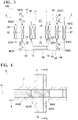
FIG. 1 is a system diagram showing a configuration of an air conditioning device for a vehicle according to an embodiment of the present disclosure and is a diagram showing a state in which a second vehicle interior heat exchanger (heater core) is frozen. -
FIG. 2 is a system diagram showing a configuration of the air conditioning device for the vehicle according to the embodiment of the present disclosure and is a diagram showing a state in which the second vehicle interior heat exchanger (heater core) is defrosted and a first vehicle interior heat exchanger (cooler core) is frozen. -
FIG. 3 is a system diagram showing a configuration of the air conditioning device for the vehicle according to the embodiment of the present disclosure and is a diagram showing a state in which the first vehicle interior heat exchanger (cooler core) is defrosted. -
FIG. 4 is a cross-sectional view showing a configuration of a valve device as a switching unit according to the embodiment of the present disclosure. -
FIG. 5 is a cross-sectional view taken along the line A-A ofFIG. 4 . -
FIG. 6 is a schematic diagram showing a configuration of a first communication path of a first valve body. -
FIG. 7 is a perspective view showing a configuration of the first valve body. -
FIG. 8 is a schematic diagram showing a configuration of a second communication path of a second valve body. -
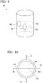
FIG. 9 is a perspective view showing a configuration of the second valve body. -
FIG. 10 is a schematic diagram showing a configuration of a third communication path of a third valve body. -
FIG. 11 is a perspective view showing a configuration of the third valve body. -
FIG. 12 is a schematic diagram showing a configuration of a fourth communication path of a fourth valve body. -
FIG. 13 is a perspective view showing a configuration of the fourth valve body. - Hereinafter, an
air conditioning device 100 for a vehicle according to an embodiment of the present disclosure will be described with reference toFIGs. 1 to 13 . Theair conditioning device 100 for the vehicle is mounted on a transport machine (vehicle) such as an automobile or a truck. That is, thisair conditioning device 100 for the vehicle adjusts the temperature difference between the inside and outside of the vehicle. As shown inFIG. 1 , theair conditioning device 100 for the vehicle includes arefrigeration cycle 1, a high-temperatureheat medium circuit 2, a low-temperatureheat medium circuit 3, afirst connection line 41, asecond connection line 42, athird connection line 43, afourth connection line 44, and aswitching unit 5. Additionally, inFIGs. 1 to 3 , the pipes that are open are indicated by solid lines and the pipes that are closed are indicated by dashed lines. - The
refrigeration cycle 1 includes arefrigerant line 11 which is a pipe through which a refrigerant is circulated, acompressor 12 which is disposed on therefrigerant line 11, acondenser 13, anexpansion valve 14, and anevaporator 15. Thecompressor 12, thecondenser 13, theexpansion valve 14, and theevaporator 15 are arranged in this order on therefrigerant line 11. Further, when therefrigeration cycle 1 is in operation, the refrigerant also passes through each device in this order. - The
compressor 12 feeds the refrigerant in therefrigerant line 11 with increasing the pressure thereof. Accordingly, the pressure and temperature of the refrigerant after passing through thecompressor 12 rises as compared with the refrigerant before passing through the compressor. Thecondenser 13 exchanges heat between the refrigerant flowing into thecondenser 13 and the cooling water (described later) flowing through the high-temperatureheat medium circuit 2. Theexpansion valve 14 sharply decreases the temperature by decreasing the pressure of the refrigerant passing through theexpansion valve 14. Theevaporator 15 exchanges heat between the refrigerant flowing into theevaporator 15 and the heat medium (described later) flowing through the low-temperatureheat medium circuit 3. - The high-temperature
heat medium circuit 2 includes a high-temperatureheat medium line 23 through which cooling water is introduced to thecondenser 13, a cooler core 22 (first vehicle interior heat exchanger) and a heater core 21 (second vehicle interior heat exchanger) which are arranged in parallel on the high-temperatureheat medium line 23, and a high-temperatureheat medium pump 24 which feeds cooling water with increasing the pressure thereof. That is, the heat medium flowing out of thecondenser 13 can be branched and flowed toward each of theheater core 21 and thecooler core 22. Theheater core 21 and thecooler core 22 are heat exchangers arranged on the vehicle interior side. Theheater core 21 and thecooler core 22 exchange heat between the indoor/outdoor air and to the cooling water. Additionally, it is possible to perform an operation of increasing a room temperature while suppressing an increase in indoor humidity in such a manner that thecooler core 22 first cools the air to remove the moisture and then theheater core 21 heats the air in the heating operation. - The low-temperature
heat medium circuit 3 includes a low-temperatureheat medium line 33 through which cooling water is introduced to theevaporator 15, a first vehicleexterior heat exchanger 31 and a second vehicleexterior heat exchanger 32 which are arranged in parallel on the low-temperatureheat medium line 33, and a low-temperatureheat medium pump 34 which feeds a heat medium with increasing the pressure thereof. That is, the cooling water flowing out of theevaporator 15 can be branched and flowed toward each of the first vehicleexterior heat exchanger 31 and the second vehicleexterior heat exchanger 32. The first vehicleexterior heat exchanger 31 and the second vehicleexterior heat exchanger 32 are heat exchangers arranged on the vehicle exterior side. The first vehicleexterior heat exchanger 31 and the second vehicleexterior heat exchanger 32 exchange heat between the outdoor air and the heat medium. - The
first connection line 41 and thesecond connection line 42 are pipes which connect the high-temperatureheat medium circuit 2 to the low-temperatureheat medium circuit 3. That is, the heat medium flows through thefirst connection line 41 and thesecond connection line 42. Thefirst connection line 41 and thesecond connection line 42 are parallel to each other. That is, the high-temperatureheat medium circuit 2 and the low-temperatureheat medium circuit 3 can be connected by at least one of thefirst connection line 41 and thesecond connection line 42 in accordance with the selected operation state (operation mode) of theair conditioning device 100 for the vehicle. - The
third connection line 43 and thefourth connection line 44 are also pipes which connect the high-temperatureheat medium circuit 2 to the low-temperatureheat medium circuit 3. That is, the heat medium flows through thethird connection line 43 and thefourth connection line 44. Thethird connection line 43 and thefourth connection line 44 are parallel to each other. That is, the high-temperatureheat medium circuit 2 and the low-temperatureheat medium circuit 3 can be connected by at least one of thethird connection line 43 and thefourth connection line 44 in addition to at least one of thefirst connection line 41 and thesecond connection line 42 in accordance with the selected operation state (operation mode) of theair conditioning device 100 for the vehicle. Further, in this embodiment, an in-vehicle device 90 which is an auxiliary device of the vehicle is disposed only on thethird connection line 43. A detailed example of the in-vehicle device 90 is a battery. - The
fifth connection line 45 connects the high-temperatureheat medium circuit 2 and the low-temperatureheat medium circuit 3 by bypassing thethird connection line 43 and thefourth connection line 44. - The path of the cooling water flowing through the high-temperature
heat medium circuit 2, the low-temperatureheat medium circuit 3, thefirst connection line 41, thesecond connection line 42, thethird connection line 43, thefourth connection line 44, and thefifth connection line 45 can be switched by theswitching unit 5. In other words, the operation state (operation mode) of theair conditioning device 100 for the vehicle is switched by switching the cooling water flowing path. - The
switching unit 5 is a valve device (switching valve) capable of switching the flow state of the cooling water between flow paths to which theswitching unit 5 is connected. As shown inFIG. 1 , in this embodiment, each switchingunit 5 is provided for each of a plurality of (eight) connection portions connecting each flow path. In these eight switchingunits 5, theswitching unit 5 provided at the connection portion on the side close to thecooler core 22 in two connection portions of thefirst connection line 41 and thesecond connection line 42 is afirst valve device 51. - The switching
units 5 provided at two branch points between theheater core 21 and thecooler core 22 of the high-temperatureheat medium circuit 2 are respectively asecond valve device 52 and athird valve device 53. Thethird valve device 53 is provided at the branch point between theheater core 21 and thecondenser 13 and on the installation side of the high-temperatureheat medium pump 24. Thesecond valve device 52 is provided at the branch point between thecooler core 22 and thecondenser 13 and on the non-installation side of the high-temperatureheat medium pump 24. - The
switching unit 5 provided at the connection portion on the side close to thecooler core 22 in two connection portions of thethird connection line 43 and thefourth connection line 44 is afourth valve device 54. - Similarly, the
switching unit 5 provided at the connection portion on the side close to the second vehicleexterior heat exchanger 32 in two connection portions of thefirst connection line 41 and thesecond connection line 42 is afifth valve device 55. - The switching
units 5 provided at two branch points between the first vehicleexterior heat exchanger 31 and the second vehicleexterior heat exchanger 32 of the low-temperatureheat medium circuit 3 are respectively asixth valve device 56 and aseventh valve device 57. Thesixth valve device 56 is provided at the branch point between the first vehicleexterior heat exchanger 31 and the second vehicleexterior heat exchanger 32 and on the installation side of the low-temperatureheat medium pump 34. Theseventh valve device 57 is provided at the branch point between the first vehicleexterior heat exchanger 31 and the second vehicleexterior heat exchanger 32 and on the non-installation side of the low-temperatureheat medium pump 34. - The
switching unit 5 provided at the connection portion on the side close to the second vehicleexterior heat exchanger 32 in two connection portions of thethird connection line 43 and thefourth connection line 44 is aneighth valve device 58. - In
Figs. 1 to 3 , the reference numerals attached in the vicinity of each switchingunit 5 indicate the open state of each switchingunit 5. Hereinafter, a detailed configuration of theswitching unit 5 will be described with reference toFigs. 4 to 13 and an example of the operation mode of theair conditioning device 100 for the vehicle will be described with reference toFigs. 1 to 3 according to the open state indicated by the reference numerals. - As shown in
FIG. 4 , theswitching unit 5 includes a plurality of (four)valve bodies 6, avalve casing 7 which accommodates thesevalve bodies 6 and forms a plurality of (four)flow paths actuator 8 which drives thevalve body 6. - Each
valve body 6 has a columnar shape extending along the axis O.Four valve bodies 6 are arranged in thevalve casing 7 in the direction of the axis O. Eachvalve body 6 is driven by theactuator 8 to be movable in a reciprocating manner along the axis O in thevalve casing 7 and rotatable around the axis O. That is, when thevalve body 6 is moved in a reciprocating manner in the direction of the axis O, any one of fourvalve bodies 6 having different shapes can be selectively used. A detailed configuration of eachvalve body 6 will be described later. - The
valve casing 7 is formed in a tubular shape which covers fourvalve bodies 6 from the outer peripheral side with respect to the axis O. Further, as shown inFIG. 5 , thevalve casing 7 is provided with fourflow paths heat medium circuit 2 and the low-temperatureheat medium circuit 3. Theflow paths flow paths - As shown in
Figs. 6 and7 , four opening portions (first opening portions H1) which open in four directions at intervals of 90° in the circumferential direction with respect to the axis O are formed at one (first valve body 61) of fourvalve bodies 6. Further, the pair of first opening portions H1 adjacent to each other in the circumferential direction in these four first opening portions H1 communicates with each other by a first communication path C1 formed in thefirst valve body 61.FIG. 6 schematically shows the shape of thefirst valve body 61 and corresponds to the reference numerals shown inFigs. 1 to 3 . For example, in thefirst valve device 51, thesecond valve body 62 is selected and the high-temperatureheat medium circuit 2, thefirst connection line 41, and thesecond connection line 42 are in the communication state by the posture of thesecond valve body 62. In the following description, the type and posture of thevalve body 6 selected in this way are indicated by the reference numerals inFigs. 1 to 3 . - As shown in
Figs. 8 and9 , three opening portions (second opening portions H2) which open in three directions at intervals in the circumferential direction with respect to the axis O are formed at one (second valve body 62) of fourvalve bodies 6. Further, these three second opening portions H2 communicate with each other by a second communication path C2 formed in thesecond valve body 62. Additionally, the circumferential gap between the second opening portions H2 is not constant. That is, the second communication path C2 has a T shape when viewed from the direction of the axis O. Thus, only any three flow paths of fourflow paths second valve body 62.FIG. 8 schematically shows the shape of thesecond valve body 62 and corresponds to the reference numerals shown inFigs. 1 to 3 . - As shown in
Figs. 10 and11 , two opening portions (third opening portions H3) which open in two directions at intervals of 180° in the circumferential direction with respect to the axis O are formed at one (third valve body 63) of fourvalve bodies 6. Further, these third opening portions H3 communicate with each other by a third communication path C3 formed in thethird valve body 63. Only any two flow paths of fourflow paths third valve body 63.FIG. 10 schematically shows the shape of thethird valve body 63 and corresponds to the reference numerals shown inFigs. 1 to 3 . - As shown in
Figs. 12 and13 , four opening portions (fourth opening portions H4) which open in four directions at intervals of 90° in the circumferential direction with respect to the axis O are formed at one (fourth valve body 64) of fourvalve bodies 6. Further, the pair of fourth opening portions H4 located on both sides in the radial direction with respect to the axis O in these four fourth opening portions H4 communicates with each other by a fourth communication path C4 formed in eachfourth valve body 64. Two fourth communication paths C4 are respectively curved not to interfere with each other in the direction of the axis O in thefourth valve body 64. Additionally, inFIG. 13 , in order to avoid complication of illustration, only one fourth communication path C4 is shown and the other fourth communication path C4 is not shown. Only any two flow paths of fourflow paths fourth valve body 64.FIG. 12 schematically shows the shape of thefourth valve body 64 and corresponds to the reference numerals shown inFigs. 1 to 3 . - Next, the operation of the "freezing mode" and the "defrosting drying mode" which is one of the operation modes of the
air conditioning device 100 for the vehicle will be described with reference toFIG. 1 . Additionally, the flow paths of the refrigerant and the cooling water described below are realized by setting eachswitching unit 5 to the state shown by the reference numeral inFIG. 1 . - The freezing mode and the defrosting drying mode are also performed for the purpose of cleaning the vehicle interior side heat exchanger (the
heater core 21 and the cooler core 22). When cleaning, first, the moisture in the air is condensed and frozen on the surface of the cooler core 22 (the first vehicle interior heat exchanger) (FIG. 1 ). Next, the surface of thecooler core 22 is washed by using the moisture melted by heating thecooler core 22 and is continuously further heated to perform the mode (defrosting drying mode) of drying thecooler core 22 and the freezing mode for the heater core 21 (the second vehicle interior heat exchanger) is performed (FIG. 2 ). Then, theheater core 21 is heated to perform the defrosting drying mode (FIG. 3 ). Hereinafter, the state of each drawing will be described. - In the state of
FIG. 1 , only the low-temperature cooling water flowing through the low-temperatureheat medium circuit 3 flows into thecooler core 22 through thesecond connection line 42. Accordingly, the moisture generated on the surface of thecooler core 22 is frozen. The heat medium flowing out of thecooler core 22 is returned to the low-temperatureheat medium circuit 3 through thefourth connection line 44. - In the state of
FIG. 2 , the low-temperature heat medium flowing through the low-temperatureheat medium circuit 3 flows into only theheater core 21 through thesecond connection line 42. Accordingly, the moisture generated on the surface of theheater core 21 is frozen. On the other hand, at this time, a heat medium that has become hot due to heat exchange with the refrigerant in thecondenser 13 flows into thecooler core 22. Thus, the moisture frozen on the surface of thecooler core 22 is heated and melted (defrosted). Adhesions such as bacteria and dust captured with moisture during freezing are washed away with moisture during melting. After that, thecooler core 22 is dried by continuing heating. That is, this operation cleans the surface of theheater core 21 and suppresses the generation of bacteria and mold in accordance with drying. - Next, in the state of
FIG. 3 , a heat medium that has become hot due to heat exchange with the refrigerant in thecondenser 13 flows into theheater core 21. Thus, the moisture frozen on the surface of theheater core 21 is heated and melted (defrosted). Adhesions such as bacteria and dust captured with moisture during freezing are washed away with moisture during melting. Then, theheater core 21 is continuously further heated to be dried. That is, the surface of thecooler core 22 is cleaned by this operation and the generation of bacteria and mold is suppressed in accordance with drying. - As described above, according to this embodiment, in the freezing mode, only the low-temperature heat medium is supplied from the low-temperature
heat medium circuit 3 to theheater core 21 or thecooler core 22 which is the vehicle interior heat exchanger. Accordingly, the moisture condensed on the surface of theheater core 21 or thecooler core 22 is frozen. At this time, the bacteria and mold had grown on the surface are frozen together with the moisture. Then, the cooling water that has become hot by the heat exchange with the refrigerant in thecondenser 13 by performing the defrosting drying mode is supplied to theheater core 21 or thecooler core 22. Accordingly, the frozen moisture is melted (defrosted). As a result, adhesions such as bacteria and dust captured with moisture during freezing can be washed away with moisture. After that, theheater core 21 or thecooler core 22 is dried by continuing heating. As a result, the generation of the bacteria and mold is suppressed. Thus, it is possible to perform a hygienic operation of theair conditioning device 100 for the vehicle for a longer period. - In addition, according to the above-described configuration, it is possible to switch the communication states of the plurality of
flow paths valve bodies 6 in a reciprocating manner in the direction of the axis O or rotating the valve casing around the axis O in thevalve casing 7. In particular, since a plurality of required valve devices (switching unit 5) can be unified into only one configuration, the number of parts can be reduced. Further, it is possible to omit the step of selecting and installing an appropriate type from a plurality of types of valve devices at the time of manufacturing. As a result, it is possible to reduce the manufacturing cost or the maintenance cost. - According to the above-described configuration, it is possible to communicate a pair of adjacent flow paths of four
flow paths first valve body 61. Further, it is possible to selectively communicate two flow paths of fourflow paths first valve body 61 around the axis O. Accordingly, it is possible to switch the communication states of theflow paths - According to the above-described configuration, it is possible to communicate three flow paths of four
flow paths second valve body 62. Further, it is possible to selectively communicate three flow paths of fourflow paths second valve body 62 around the axis O. Accordingly, it is possible to switch the communication states of theflow paths - According to the above-described configuration, it is possible to communicate two flow paths of four
flow paths third valve body 63. Further, it is possible to selectively communicate two flow paths of fourflow paths third valve body 63 around the axis O. Accordingly, it is possible to switch the communication states of theflow paths - According to the above-described configuration, it is possible to communicate two flow paths located on both sides in the radial direction of four
flow paths fourth valve body 64. Further, it is possible to selectively communicate two flow paths of fourflow paths fourth valve body 64 around the axis O. Accordingly, it is possible to switch the communication states of theflow paths - The embodiments of the present disclosure have been described in detail with reference to the drawings. Additionally, the specific configuration is not limited to the above embodiments and includes design changes and the like within a range that does not deviate from the gist of the present disclosure. For example, it is possible to operate the
air conditioning device 100 for the vehicle in other modes including not only the strong heating mode and the heating defrosting mode but also the cooling mode and the like by appropriately switching the state of each switchingunit 5. - Further, in the above-described embodiments, an example in which the freezing mode and the defrosting drying mode are sequentially performed by the pair of
heater cores 21 has been described. However, these modes may be performed simultaneously by the pair ofheater cores 21 or may be performed in the reverse order of the above-described embodiments. - [Appendix] The
air conditioning device 100 for the vehicle described in each embodiment is grasped as follows, for example. - (1) The air conditioning device 100 for the vehicle according to a first aspect includes: the refrigeration cycle 1 including the compressor 12, the condenser 13, the expansion valve 14, and the evaporator 15 through which a refrigerant is sequentially flowed; the high-temperature heat medium circuit 2 through which the high-temperature heat medium has exchanged heat with the refrigerant in the condenser 13 is circulated; the low-temperature heat medium circuit 3 through which the low-temperature heat medium has exchanged heat with the refrigerant in the evaporator 15 is circulated; the connection lines 41, 42, 43, 44, and 45 connecting the high-temperature heat medium circuit 2 to the low-temperature heat medium circuit 3; the plurality of vehicle interior heat exchangers 21 and 22 which are allowed to be introduced the heat medium thereinto; the plurality of vehicle exterior heat exchangers 31 and 32 which are allowed to be introduced the heat medium thereinto; and the switching unit 5 which is configured to switch the operation state of the air conditioning device to a first mode allowing to connect the vehicle interior heat exchangers to the high-temperature heat medium circuit 2, a second mode allowing to connect the vehicle interior heat exchangers to the low-temperature heat medium circuit 3, and a third mode not allowing to connect the vehicle interior heat exchangers to any one of the high-temperature heat medium circuit 2 and the low-temperature heat medium circuit 3.
- According to the above-described configuration, in the freezing mode, only the low-temperature heat medium is supplied from the low-temperature
heat medium circuit 3 to theheater core 21 or thecooler core 22 which is the vehicle interior heat exchanger. Accordingly, the moisture condensed on the surface of theheater core 21 or thecooler core 22 is frozen. At this time, adhesions such as bacteria and mold had grown on the surface are frozen together with the moisture. Then, the heat medium that has become hot by the heat exchange with the refrigerant in thecondenser 13 by performing the defrosting drying mode is supplied to theheater core 21 or thecooler core 22. Accordingly, the frozen moisture is melted (defrosted). As a result, adhesions such as bacteria and dust captured with moisture during freezing are washed away with moisture and the surface of theheater core 21 or thecooler core 22 is dried. That is, the surface of theheater core 21 or thecooler core 22 is cleaned by this operation and the generation of bacteria and mold is suppressed in accordance with drying. - (2) In the
air conditioning device 100 for the vehicle according to a second aspect, the high-temperatureheat medium circuit 2 includes the first and second vehicle interior heat exchangers (thecooler core 22 and the heater core 21), and wherein theswitching unit 5 is configured to operate the air conditioning device in a freezing mode supplying only the heat medium from the low-temperatureheat medium circuit 3 to at least one vehicle interior heat exchanger of the first and second vehicle interior heat exchangers and freezing a moisture generated on a surface of the vehicle interior heat exchanger. - According to the above-described configuration, it is possible to clean at least one of the first and second vehicle interior heat exchangers (the
cooler core 22 and the heater core 21) by operating the air conditioning device in the freezing mode. - (3) In the
air conditioning device 100 for the vehicle according to a third aspect, theswitching unit 5 is configured to operate the air conditioning device in a defrosting mode supplying a heat medium, exchanging heat with the refrigerant in thecondenser 13, to the vehicle interior heat exchanger to be heated and melting the frozen moisture after operating the air conditioning device in the freezing mode. - According to the above-described configuration, adhesions such as bacteria and dust captured with moisture during freezing are washed away with moisture during melting. By this operation, the surface of the vehicle interior heat exchanger can be cleaned.
- (4) In the
air conditioning device 100 for the vehicle according to a fourth aspect, theswitching unit 5 is configured to operate the air conditioning device in a drying mode drying the surface of the vehicle interior heat exchanger by continuously further heating the vehicle interior heat exchanger after operating the air conditioning device in the defrosting mode. - According to the above-described configuration, adhesions such as bacteria and dust captured with moisture on the surface of the vehicle interior heat exchanger during the operation in the freezing mode are washed away with the moisture by the operation in the defrosting mode. Further, when the heating is continued in the drying mode, the surface of the vehicle interior heat exchanger is dried. In this way, it is possible to suppress the generation of bacteria and mold by drying the surface.
- (5) In the
air conditioning device 100 for the vehicle according to a fifth aspect, theswitching unit 5 includes a plurality of valve devices which allows to change the flow states of the high-temperatureheat medium circuit 2 and the low-temperatureheat medium circuit 3, and wherein each of the plurality of valve devices includes the plurality ofvalve bodies 6 which are formed in a columnar shape centered on the axis O, are arranged in the direction of the axis O, and are rotatable around the axis O, thevalve casing 7 which covers the plurality ofvalve bodies 6 and forms fourflow paths heat medium circuit 2 and the low-temperatureheat medium circuit 3, and theactuator 8 which moves the plurality ofvalve bodies 6 in a reciprocating manner in the direction of the axis O and rotate the plurality of valve bodies around the axis O in thevalve casing 7. - According to the above-described configuration, it is possible to switch the communication states of the plurality of
flow paths valve bodies 6 in a reciprocating manner in the direction of the axis O or rotating the plurality of valve bodies around the axis O in thevalve casing 7. In particular, a plurality of required valve devices can be unified into only one configuration. Furthermore, since it is possible to easily increase the number of connection points, it is possible to ensure the expandability of the device. Further, it is possible to omit the step of selecting and installing an appropriate type from a plurality of types of valve devices at the time of manufacturing. As a result, it is possible to reduce the manufacturing cost or the maintenance cost. - (6) In the
air conditioning device 100 for the vehicle according to a sixth aspect, one of the plurality ofvalve bodies 6 is thefirst valve body 61 in which the first opening portions H1 are formed to open in four directions at intervals in the circumferential direction with respect to the axis O and the first communication path C1 is formed to communicate the pair of first opening portions H1 adjacent to each other in the circumferential direction in thevalve body 6. - According to the above-described configuration, it is possible to communicate a pair of adjacent flow paths of four
flow paths flow paths first valve body 61 around the axis O. Accordingly, it is possible to switch the communication states of theflow paths - (7) In the
air conditioning device 100 for the vehicle according to a seventh aspect, one of the plurality ofvalve bodies 6 is thesecond valve body 62 in which the second opening portions H2 are formed to open in three directions at intervals in the circumferential direction with respect to the axis O and the second communication path C2 is formed to communicate the three second opening portions H2 in thevalve body 6. - According to the above-described configuration, it is possible to communicate three flow paths of four
flow paths flow paths second valve body 62 around the axis O. Accordingly, it is possible to switch the communication states of theflow paths - (8) In the
air conditioning device 100 for the vehicle according to an eighth aspect, one of the plurality ofvalve bodies 6 is thethird valve body 63 in which the third opening portions H3 are formed to open in two directions at intervals in the circumferential direction with respect to the axis O and the third communication path C3 is formed to communicate the two third opening portions H3 in thevalve body 6. - According to the above-described configuration, it is possible to communicate two flow paths of four
flow paths flow paths third valve body 63 around the axis O. Accordingly, it is possible to switch the communication states of theflow paths - (9) In the
air conditioning device 100 for the vehicle according to a ninth aspect, one of the plurality ofvalve bodies 6 is thefourth valve body 64 in which the fourth opening portions H4 are formed to open in four directions at intervals in the circumferential direction with respect to the axis O and the fourth communication path C4 is formed to communicate the pair of fourth opening portions H4 located on both sides in the radial direction with respect to the axis O in thevalve body 6. - According to the above-described configuration, it is possible to communicate two flow paths located on both sides in the radial direction of four
flow paths flow paths fourth valve body 64 around the axis O. Accordingly, it is possible to switch the communication states of theflow paths - According to the air conditioning device for the vehicle of the present disclosure, it is possible to perform a hygienic operation for a longer period.
- 100 Air conditioning device for vehicle
- 1 Refrigeration cycle
- 2 High-temperature heat medium circuit
- 3 Low-temperature heat medium circuit
- 5 Switching unit
- 6 Valve body
- 7 Valve casing
- 8 Actuator
- 11 Refrigerant line
- 12 Compressor
- 13 Condenser
- 14 Expansion valve
- 15 Evaporator
- 21 Heater core
- 22 Cooler core
- 23 High-temperature heat medium line
- 24 High-temperature heat medium pump
- 31 First vehicle exterior heat exchanger
- 32 Second vehicle exterior heat exchanger
- 33 Low-temperature heat medium line
- 34 Low-temperature heat medium pump
- 41 First connection line
- 42 Second connection line
- 43 Third connection line
- 44 Fourth connection line
- 45 Fifth connection line
- 51 First valve device
- 52 Second valve device
- 53 Third valve device
- 54 Fourth valve device
- 55 Fifth valve device
- 56 Sixth valve device
- 57 Seventh valve device
- 58 Eighth valve device
- 61 First valve body
- 62 Second valve body
- 63 Third valve body
- 64 Fourth valve body
- 71, 72, 73, 74 Flow path
- 90 In-vehicle device
- C1 First communication path
- C2 Second communication path
- C3 Third communication path
- C4 Fourth communication path
- H1 First opening portion
- H2 Second opening portion
- H3 Third opening portion
- H4 Fourth opening portion
- O Axis
Claims (9)
- An air conditioning device for a vehicle comprising:a refrigeration cycle including a compressor, a condenser, an expansion valve, and an evaporator through which a refrigerant is sequentially flowed;a high-temperature heat medium circuit through which a high-temperature heat medium has exchanged heat with the refrigerant in the condenser is circulated;a low-temperature heat medium circuit through which a low-temperature heat medium has exchanged heat with the refrigerant in the evaporator is circulated;a connection line connecting the high-temperature heat medium circuit to the low-temperature heat medium circuit;a plurality of vehicle interior heat exchangers which are allowed to be introduced the heat medium thereinto; anda switching unit which is configured to switch an operation state of the air conditioning device to a first mode allowing to connect the vehicle interior heat exchangers to the high-temperature heat medium circuit, a second mode allowing to connect the vehicle interior heat exchangers to the low-temperature heat medium circuit, or a third mode not allowing to connect the vehicle interior heat exchangers to any one of the high-temperature heat medium circuit and the low-temperature heat medium circuit.
- The air conditioning device for the vehicle according to claim 1,wherein the high-temperature heat medium circuit includes the first and second vehicle interior heat exchangers, andwherein the switching unit is configured to operate the air conditioning device in a freezing mode supplying only a heat medium from the low-temperature heat medium circuit to at least one vehicle interior heat exchanger of the first and second vehicle interior heat exchangers and freezing a moisture generated on a surface of the vehicle interior heat exchanger.
- The air conditioning device for the vehicle according to claim 2,
wherein the switching unit is configured to operate the air conditioning device in a defrosting mode supplying a heat medium, which has exchanged heat with the refrigerant in the condenser, to the one vehicle interior heat exchanger to be heated and melting the frozen moisture after operating the air conditioning device in the freezing mode. - The air conditioning device for the vehicle according to claim 3,
wherein the switching unit is configured to operate the air conditioning device in a drying mode drying the surface of the vehicle interior heat exchanger by continuously further heating the vehicle interior heat exchanger after operating the air conditioning device in the defrosting mode. - The air conditioning device for the vehicle according to any one of claims 1 to 4,
wherein the switching unit includes a plurality of valve devices which allows to change flow states of the high-temperature heat medium circuit and the low-temperature heat medium circuit, and wherein each of the plurality of valve devices includesa plurality of valve bodies which are formed in a columnar shape centered on an axis, are arranged in a direction of the axis, and are rotatable around the axis,a valve casing which covers the plurality of valve bodies and forms four flow paths communicating with at least one of the high-temperature heat medium circuit and the low-temperature heat medium circuit, andan actuator which moves the plurality of valve bodies in the direction of the axis in a reciprocating manner and rotates the plurality of valve bodies around the axis in the valve casing. - The air conditioning device for the vehicle according to claim 5,
wherein one of the plurality of valve bodies is a first valve body in which first opening portions are formed to open in four directions at intervals in a circumferential direction with respect to the axis and a first communication path is formed to communicate a pair of the first opening portions adjacent to each other in the circumferential direction in the valve body. - The air conditioning device for the vehicle according to claim 5 or 6,
wherein one of the plurality of valve bodies is a second valve body in which second opening portions are formed to open in three directions at intervals in a circumferential direction with respect to the axis and a second communication path is formed to communicate the three second opening portions in the valve body. - The air conditioning device for the vehicle according to any one of claims 5 to 7,
wherein one of the plurality of valve bodies is a third valve body in which third opening portions are formed to open in two directions at intervals in a circumferential direction with respect to the axis and a third communication path is formed to communicate the two third opening portions in the valve body. - The air conditioning device for the vehicle according to any one of claims 5 to 8,
wherein one of the plurality of valve bodies is a fourth valve body in which fourth opening portions are formed to open in four directions at intervals in a circumferential direction with respect to the axis and a fourth communication path is formed to communicate the pair of fourth opening portions located on both sides in a radial direction with respect to the axis in the valve body.
Applications Claiming Priority (2)
| Application Number | Priority Date | Filing Date | Title |
|---|---|---|---|
| JP2020015526A JP7377116B2 (en) | 2020-01-31 | 2020-01-31 | Vehicle air conditioner |
| PCT/JP2021/003048 WO2021153672A1 (en) | 2020-01-31 | 2021-01-28 | Air conditioning device for vehicle |
Publications (4)
| Publication Number | Publication Date |
|---|---|
| EP4086096A1 true EP4086096A1 (en) | 2022-11-09 |
| EP4086096A4 EP4086096A4 (en) | 2023-06-28 |
| EP4086096B1 EP4086096B1 (en) | 2024-09-11 |
| EP4086096C0 EP4086096C0 (en) | 2024-09-11 |
Family
ID=77079175
Family Applications (1)
| Application Number | Title | Priority Date | Filing Date |
|---|---|---|---|
| EP21747839.5A Active EP4086096B1 (en) | 2020-01-31 | 2021-01-28 | Air conditioning device for vehicle |
Country Status (5)
| Country | Link |
|---|---|
| US (1) | US12208661B2 (en) |
| EP (1) | EP4086096B1 (en) |
| JP (1) | JP7377116B2 (en) |
| CN (1) | CN115243910B (en) |
| WO (1) | WO2021153672A1 (en) |
Cited By (1)
| Publication number | Priority date | Publication date | Assignee | Title |
|---|---|---|---|---|
| EP4074529A4 (en) * | 2020-01-31 | 2023-06-21 | Mitsubishi Heavy Industries Thermal Systems, Ltd. | VEHICLE AIR CONDITIONING DEVICE |
Families Citing this family (4)
| Publication number | Priority date | Publication date | Assignee | Title |
|---|---|---|---|---|
| JP7593136B2 (en) * | 2021-01-25 | 2024-12-03 | 株式会社デンソー | Thermal Management System |
| WO2023162270A1 (en) * | 2022-02-28 | 2023-08-31 | 三菱重工サーマルシステムズ株式会社 | Vehicle refrigeration cycle unit |
| WO2023162258A1 (en) * | 2022-02-28 | 2023-08-31 | 三菱重工サーマルシステムズ株式会社 | Vehicle cooling cycle unit |
| DE102024209437A1 (en) * | 2024-09-27 | 2026-04-02 | Zf Friedrichshafen Ag | Thermal management system |
Family Cites Families (19)
| Publication number | Priority date | Publication date | Assignee | Title |
|---|---|---|---|---|
| BE557037A (en) * | 1956-05-02 | |||
| JPS50101226U (en) | 1974-01-24 | 1975-08-21 | ||
| WO2011048724A1 (en) | 2009-10-22 | 2011-04-28 | ダイキン工業株式会社 | Flow path switching valve, and air conditioner provided therewith |
| JP6101703B2 (en) * | 2011-12-14 | 2017-03-22 | コーニンクレッカ フィリップス エヌ ヴェKoninklijke Philips N.V. | Reversing valve and high frequency vibration airflow generator |
| JP6015184B2 (en) * | 2012-07-18 | 2016-10-26 | 株式会社デンソー | Thermal management system for vehicles |
| JP6112039B2 (en) * | 2013-04-08 | 2017-04-12 | 株式会社デンソー | Thermal management system for vehicles |
| JP6233009B2 (en) | 2013-12-26 | 2017-11-22 | 株式会社デンソー | Air conditioner for vehicles |
| EP2940357A1 (en) * | 2014-04-30 | 2015-11-04 | Esbe AB | Fluid control valve |
| DE102014111971B4 (en) | 2014-08-21 | 2021-07-29 | Denso Automotive Deutschland Gmbh | Air conditioning for a vehicle |
| DE102014226346A1 (en) | 2014-12-18 | 2016-06-23 | Bayerische Motoren Werke Aktiengesellschaft | Heating system for an electric or hybrid vehicle |
| JP2016132429A (en) * | 2015-01-22 | 2016-07-25 | 株式会社デンソー | Refrigeration cycle equipment for vehicles |
| JP6540180B2 (en) * | 2015-04-14 | 2019-07-10 | 株式会社デンソー | Vehicle thermal management system |
| JP6365434B2 (en) | 2015-06-24 | 2018-08-01 | 株式会社デンソー | Vehicle thermal management device |
| JP6555112B2 (en) | 2015-12-11 | 2019-08-07 | 株式会社デンソー | Refrigeration cycle equipment |
| JP6739230B2 (en) | 2016-05-23 | 2020-08-12 | 株式会社不二工機 | Flow path switching valve |
| EP3617609A4 (en) * | 2017-04-28 | 2021-03-24 | Hitachi-Johnson Controls Air Conditioning, Inc. | AIR CONDITIONER |
| JP6340111B1 (en) | 2017-04-28 | 2018-06-06 | 日立ジョンソンコントロールズ空調株式会社 | Air conditioner indoor unit |
| JP7575767B2 (en) | 2018-07-26 | 2024-10-30 | 有限会社ファイバー浜松 | Joint structure of cargo securing belt |
| JP6534783B1 (en) * | 2019-03-08 | 2019-06-26 | 日立ジョンソンコントロールズ空調株式会社 | Air conditioner |
-
2020
- 2020-01-31 JP JP2020015526A patent/JP7377116B2/en active Active
-
2021
- 2021-01-28 CN CN202180011121.4A patent/CN115243910B/en active Active
- 2021-01-28 EP EP21747839.5A patent/EP4086096B1/en active Active
- 2021-01-28 WO PCT/JP2021/003048 patent/WO2021153672A1/en not_active Ceased
- 2021-01-28 US US17/795,913 patent/US12208661B2/en active Active
Cited By (2)
| Publication number | Priority date | Publication date | Assignee | Title |
|---|---|---|---|---|
| EP4074529A4 (en) * | 2020-01-31 | 2023-06-21 | Mitsubishi Heavy Industries Thermal Systems, Ltd. | VEHICLE AIR CONDITIONING DEVICE |
| US12160712B2 (en) | 2020-01-31 | 2024-12-03 | Mitsubishi Heavy Industries Thermal Systems, Ltd. | Air conditioning device for vehicle |
Also Published As
| Publication number | Publication date |
|---|---|
| JP7377116B2 (en) | 2023-11-09 |
| US20230082212A1 (en) | 2023-03-16 |
| CN115243910B (en) | 2025-08-05 |
| EP4086096A4 (en) | 2023-06-28 |
| EP4086096B1 (en) | 2024-09-11 |
| JP2021123132A (en) | 2021-08-30 |
| CN115243910A (en) | 2022-10-25 |
| US12208661B2 (en) | 2025-01-28 |
| EP4086096C0 (en) | 2024-09-11 |
| WO2021153672A1 (en) | 2021-08-05 |
Similar Documents
| Publication | Publication Date | Title |
|---|---|---|
| EP4086096B1 (en) | Air conditioning device for vehicle | |
| JP5967403B2 (en) | Air conditioner for vehicles | |
| JP6304578B2 (en) | Air conditioner for vehicles | |
| CN110466309A (en) | Vehicle cools and heats system | |
| KR20210107361A (en) | Automotive air conditioning system | |
| CN112313098A (en) | Vehicle heat treatment system | |
| JP5634849B2 (en) | Rotary four-way switching valve | |
| EP4074529B1 (en) | Air conditioning device for vehicle | |
| JP6315222B2 (en) | Units for vehicle air conditioners | |
| JP2013523505A (en) | An air conditioning loop including a heat exchanger disposed directly between two expansion members | |
| JP5636676B2 (en) | Air conditioner | |
| KR20200063382A (en) | Air-conditioning system for electric vehicles | |
| KR102817404B1 (en) | Automotive air conditioning system | |
| CN222230754U (en) | HVAC equipment | |
| JP2001219732A (en) | Air conditioner for vehicle | |
| JP5524969B2 (en) | An improved thermal device for air conditioning in an automobile passenger compartment. | |
| KR102960925B1 (en) | Hvac module and heat pump system for vehicle having the same | |
| EP4279739A1 (en) | Output device of a compressor | |
| KR101750917B1 (en) | Heat pump system for vehicle | |
| KR102830844B1 (en) | Automotive air conditioning system | |
| JP2012117694A (en) | Refrigerating device | |
| WO2024176433A1 (en) | Heat management system | |
| JP2017074833A (en) | Vehicular air conditioning device | |
| JP2005106304A (en) | Water source heat pump air conditioner | |
| KR100532054B1 (en) | Quick heating system of airconditioner for vehicle |
Legal Events
| Date | Code | Title | Description |
|---|---|---|---|
| STAA | Information on the status of an ep patent application or granted ep patent |
Free format text: STATUS: THE INTERNATIONAL PUBLICATION HAS BEEN MADE |
|
| PUAI | Public reference made under article 153(3) epc to a published international application that has entered the european phase |
Free format text: ORIGINAL CODE: 0009012 |
|
| STAA | Information on the status of an ep patent application or granted ep patent |
Free format text: STATUS: REQUEST FOR EXAMINATION WAS MADE |
|
| 17P | Request for examination filed |
Effective date: 20220804 |
|
| AK | Designated contracting states |
Kind code of ref document: A1 Designated state(s): AL AT BE BG CH CY CZ DE DK EE ES FI FR GB GR HR HU IE IS IT LI LT LU LV MC MK MT NL NO PL PT RO RS SE SI SK SM TR |
|
| DAV | Request for validation of the european patent (deleted) | ||
| DAX | Request for extension of the european patent (deleted) | ||
| A4 | Supplementary search report drawn up and despatched |
Effective date: 20230601 |
|
| RIC1 | Information provided on ipc code assigned before grant |
Ipc: B60H 1/00 20060101ALI20230525BHEP Ipc: B60H 1/32 20060101AFI20230525BHEP |
|
| GRAP | Despatch of communication of intention to grant a patent |
Free format text: ORIGINAL CODE: EPIDOSNIGR1 |
|
| STAA | Information on the status of an ep patent application or granted ep patent |
Free format text: STATUS: GRANT OF PATENT IS INTENDED |
|
| INTG | Intention to grant announced |
Effective date: 20240402 |
|
| GRAS | Grant fee paid |
Free format text: ORIGINAL CODE: EPIDOSNIGR3 |
|
| GRAA | (expected) grant |
Free format text: ORIGINAL CODE: 0009210 |
|
| STAA | Information on the status of an ep patent application or granted ep patent |
Free format text: STATUS: THE PATENT HAS BEEN GRANTED |
|
| AK | Designated contracting states |
Kind code of ref document: B1 Designated state(s): AL AT BE BG CH CY CZ DE DK EE ES FI FR GB GR HR HU IE IS IT LI LT LU LV MC MK MT NL NO PL PT RO RS SE SI SK SM TR |
|
| REG | Reference to a national code |
Ref country code: GB Ref legal event code: FG4D |
|
| REG | Reference to a national code |
Ref country code: CH Ref legal event code: EP |
|
| REG | Reference to a national code |
Ref country code: DE Ref legal event code: R096 Ref document number: 602021018703 Country of ref document: DE |
|
| REG | Reference to a national code |
Ref country code: IE Ref legal event code: FG4D |
|
| U01 | Request for unitary effect filed |
Effective date: 20240912 |
|
| U07 | Unitary effect registered |
Designated state(s): AT BE BG DE DK EE FI FR IT LT LU LV MT NL PT RO SE SI Effective date: 20241004 |
|
| PG25 | Lapsed in a contracting state [announced via postgrant information from national office to epo] |
Ref country code: NO Free format text: LAPSE BECAUSE OF FAILURE TO SUBMIT A TRANSLATION OF THE DESCRIPTION OR TO PAY THE FEE WITHIN THE PRESCRIBED TIME-LIMIT Effective date: 20241211 |
|
| PG25 | Lapsed in a contracting state [announced via postgrant information from national office to epo] |
Ref country code: GR Free format text: LAPSE BECAUSE OF FAILURE TO SUBMIT A TRANSLATION OF THE DESCRIPTION OR TO PAY THE FEE WITHIN THE PRESCRIBED TIME-LIMIT Effective date: 20241212 |
|
| PG25 | Lapsed in a contracting state [announced via postgrant information from national office to epo] |
Ref country code: HR Free format text: LAPSE BECAUSE OF FAILURE TO SUBMIT A TRANSLATION OF THE DESCRIPTION OR TO PAY THE FEE WITHIN THE PRESCRIBED TIME-LIMIT Effective date: 20240911 |
|
| PG25 | Lapsed in a contracting state [announced via postgrant information from national office to epo] |
Ref country code: RS Free format text: LAPSE BECAUSE OF FAILURE TO SUBMIT A TRANSLATION OF THE DESCRIPTION OR TO PAY THE FEE WITHIN THE PRESCRIBED TIME-LIMIT Effective date: 20241211 Ref country code: ES Free format text: LAPSE BECAUSE OF FAILURE TO SUBMIT A TRANSLATION OF THE DESCRIPTION OR TO PAY THE FEE WITHIN THE PRESCRIBED TIME-LIMIT Effective date: 20240911 |
|
| PG25 | Lapsed in a contracting state [announced via postgrant information from national office to epo] |
Ref country code: RS Free format text: LAPSE BECAUSE OF FAILURE TO SUBMIT A TRANSLATION OF THE DESCRIPTION OR TO PAY THE FEE WITHIN THE PRESCRIBED TIME-LIMIT Effective date: 20241211 Ref country code: NO Free format text: LAPSE BECAUSE OF FAILURE TO SUBMIT A TRANSLATION OF THE DESCRIPTION OR TO PAY THE FEE WITHIN THE PRESCRIBED TIME-LIMIT Effective date: 20241211 Ref country code: HR Free format text: LAPSE BECAUSE OF FAILURE TO SUBMIT A TRANSLATION OF THE DESCRIPTION OR TO PAY THE FEE WITHIN THE PRESCRIBED TIME-LIMIT Effective date: 20240911 Ref country code: GR Free format text: LAPSE BECAUSE OF FAILURE TO SUBMIT A TRANSLATION OF THE DESCRIPTION OR TO PAY THE FEE WITHIN THE PRESCRIBED TIME-LIMIT Effective date: 20241212 Ref country code: ES Free format text: LAPSE BECAUSE OF FAILURE TO SUBMIT A TRANSLATION OF THE DESCRIPTION OR TO PAY THE FEE WITHIN THE PRESCRIBED TIME-LIMIT Effective date: 20240911 |
|
| U20 | Renewal fee for the european patent with unitary effect paid |
Year of fee payment: 5 Effective date: 20250120 |
|
| PG25 | Lapsed in a contracting state [announced via postgrant information from national office to epo] |
Ref country code: IS Free format text: LAPSE BECAUSE OF FAILURE TO SUBMIT A TRANSLATION OF THE DESCRIPTION OR TO PAY THE FEE WITHIN THE PRESCRIBED TIME-LIMIT Effective date: 20250111 |
|
| PG25 | Lapsed in a contracting state [announced via postgrant information from national office to epo] |
Ref country code: SM Free format text: LAPSE BECAUSE OF FAILURE TO SUBMIT A TRANSLATION OF THE DESCRIPTION OR TO PAY THE FEE WITHIN THE PRESCRIBED TIME-LIMIT Effective date: 20240911 |
|
| PG25 | Lapsed in a contracting state [announced via postgrant information from national office to epo] |
Ref country code: CZ Free format text: LAPSE BECAUSE OF FAILURE TO SUBMIT A TRANSLATION OF THE DESCRIPTION OR TO PAY THE FEE WITHIN THE PRESCRIBED TIME-LIMIT Effective date: 20240911 Ref country code: PL Free format text: LAPSE BECAUSE OF FAILURE TO SUBMIT A TRANSLATION OF THE DESCRIPTION OR TO PAY THE FEE WITHIN THE PRESCRIBED TIME-LIMIT Effective date: 20240911 |
|
| PG25 | Lapsed in a contracting state [announced via postgrant information from national office to epo] |
Ref country code: SK Free format text: LAPSE BECAUSE OF FAILURE TO SUBMIT A TRANSLATION OF THE DESCRIPTION OR TO PAY THE FEE WITHIN THE PRESCRIBED TIME-LIMIT Effective date: 20240911 |
|
| PLBE | No opposition filed within time limit |
Free format text: ORIGINAL CODE: 0009261 |
|
| STAA | Information on the status of an ep patent application or granted ep patent |
Free format text: STATUS: NO OPPOSITION FILED WITHIN TIME LIMIT |
|
| 26N | No opposition filed |
Effective date: 20250612 |
|
| REG | Reference to a national code |
Ref country code: CH Ref legal event code: PL |
|
| PG25 | Lapsed in a contracting state [announced via postgrant information from national office to epo] |
Ref country code: MC Free format text: LAPSE BECAUSE OF FAILURE TO SUBMIT A TRANSLATION OF THE DESCRIPTION OR TO PAY THE FEE WITHIN THE PRESCRIBED TIME-LIMIT Effective date: 20240911 |
|
| GBPC | Gb: european patent ceased through non-payment of renewal fee |
Effective date: 20250128 |
|
| PG25 | Lapsed in a contracting state [announced via postgrant information from national office to epo] |
Ref country code: GB Free format text: LAPSE BECAUSE OF NON-PAYMENT OF DUE FEES Effective date: 20250128 |
|
| PG25 | Lapsed in a contracting state [announced via postgrant information from national office to epo] |
Ref country code: CH Free format text: LAPSE BECAUSE OF NON-PAYMENT OF DUE FEES Effective date: 20250131 |
|
| U20 | Renewal fee for the european patent with unitary effect paid |
Year of fee payment: 6 Effective date: 20251205 |
|
| PG25 | Lapsed in a contracting state [announced via postgrant information from national office to epo] |
Ref country code: IE Free format text: LAPSE BECAUSE OF NON-PAYMENT OF DUE FEES Effective date: 20250128 |