EP4086053A1 - Improved machine for working panels made of wood, group for protecting and cleaning the air and method for cleaning the air - Google Patents
Improved machine for working panels made of wood, group for protecting and cleaning the air and method for cleaning the air Download PDFInfo
- Publication number
- EP4086053A1 EP4086053A1 EP22170790.4A EP22170790A EP4086053A1 EP 4086053 A1 EP4086053 A1 EP 4086053A1 EP 22170790 A EP22170790 A EP 22170790A EP 4086053 A1 EP4086053 A1 EP 4086053A1
- Authority
- EP
- European Patent Office
- Prior art keywords
- working
- panel
- air
- machine
- partition
- Prior art date
- Legal status (The legal status is an assumption and is not a legal conclusion. Google has not performed a legal analysis and makes no representation as to the accuracy of the status listed.)
- Granted
Links
Images




Classifications
-
- B—PERFORMING OPERATIONS; TRANSPORTING
- B27—WORKING OR PRESERVING WOOD OR SIMILAR MATERIAL; NAILING OR STAPLING MACHINES IN GENERAL
- B27M—WORKING OF WOOD NOT PROVIDED FOR IN SUBCLASSES B27B - B27L; MANUFACTURE OF SPECIFIC WOODEN ARTICLES
- B27M1/00—Working of wood not provided for in subclasses B27B - B27L, e.g. by stretching
- B27M1/08—Working of wood not provided for in subclasses B27B - B27L, e.g. by stretching by multi-step processes
-
- B—PERFORMING OPERATIONS; TRANSPORTING
- B27—WORKING OR PRESERVING WOOD OR SIMILAR MATERIAL; NAILING OR STAPLING MACHINES IN GENERAL
- B27D—WORKING VENEER OR PLYWOOD
- B27D5/00—Other working of veneer or plywood specially adapted to veneer or plywood
- B27D5/006—Trimming, chamfering or bevelling edgings, e.g. lists
Definitions
- the present invention relates to an improved machine for working wooden pieces, air protection and cleaning unit and a method for cleaning the air.
- the invention concerns an air protection and cleaning unit for machines for working pieces made of wood, glass, fiberglass, plastic, and the like, designed and manufactured in particular to clean and filter the air within a volume around a cutting or working zone in general.
- cutting machines typically comprise an entry or loading station to arrange, manually or automatically, the panels to be worked, one or more working stations for working for these panels, and an exit or unloading station, to manually or automatically pick up the worked panels.
- each working station arranged between said loading station and said unloading station, comprises a cutting group, arranged below the working plane and equipped with a blade that protrudes at least partially with respect to said working plane by means of a respective slot.
- each working station typically comprises a pressure member for locking the panel in position during its working, which occurs by means of said blade that cuts the panel along a cutting line, transversal with respect to the advancement direction of the panel.
- the cutting takes place thanks to the movement of said cutting group along the cutting line.
- the blade moreover, is vertically movable between a rest position, in which it is arranged below said working plane, and a working position, in which it is arranged at least partially protruding with respect to said working plane.
- electrostatic charges positive and negative
- electrostatic discharges can generate electrostatic discharges and, therefore, cause the inflammation of dust or gases present around the panel being worked, causing fires and/or explosions .
- Another scope of the invention is to provide an air protection and cleaning unit for a machine for working wooden pieces and the like, which allows removing the residual materials of the working of the piece, minimizing the possibility of obstructing the paths for the passage of air around the piece to be worked.
- Another scope of the invention is to provide an air protection and cleaning unit that is highly reliable, relatively simple to manufacture, and at competitive costs if compared to the prior art.
- a machine for working panels made of wood and the like comprising: a working plane for supporting at least one panel to be worked; a working unit comprising at least one working tool, for performing a working on said at least one panel along a working zone, and a group for protecting and cleaning the air surrounding the working tool during the working of said at least one panel, comprising a first and a second partitioning member, wherein each partitioning member is movable between a rest position and an operating position such that, when said partitioning members are in said operating position, they define a volume around said working tool, and an air inlet device arranged in correspondence of said operating tool, for injecting an air flow into said volume, wherein said machine is characterized in that said air flow injected by air inlet device of said group for protecting and cleaning the air is an ionized air flow for reducing or neutralizing electrostatic charges generated during the working of said at least one panel.
- said group for protecting and cleaning the air may comprise a first suction device arranged in correspondence of said working zone, wherein said first suction device is capable of sucking the air and materials and waste resulting from the working of said at least one panel which are present within said volume, so as to clean the zone around said at least one panel during working.
- said group for protecting and cleaning the air may comprise a second suction device, arranged in correspondence of said working zone, above said first and second partitioning members, wherein said second suction device is capable of sucking the air and materials and waste resulting from the working of said at least one panel which are present within said volume, so as to clean the zone around said at least one panel during working.
- said first partitioning member may be a first partition movable between said rest position, wherein it is at least partially raised with respect to said working plane, and said operating position, wherein it touches said at least one panel and/or said working plane and vice versa
- said second partitioning member may be a second partition movable between said rest position, wherein it is at least partially raised with respect to said working plane, and said operating position, wherein it touches said at least one panel and/or said working plane and vice versa.
- said first partition may be made of a first plurality of strips arranged all side by side and movable along relevant guides between said rest position and said operating position and vice versa
- said second partition is made of a second plurality of strips arranged all side by side and movable along relevant guides between said rest position and said operating position and vice versa, such that, when in said operating position, each partition is capable of adapting itself to the section of the panel arranged on said working plane.
- said machine may comprise a locking member for locking said at least one panel during working, each partitioning member may be connected to said locking member, said air inlet device may be arranged in proximity to a first end of said locking member, and said first suction device may be arranged in proximity to a second end of said locking member.
- said locking member may comprise a first support arranged on one side of said locking member, wherein said support is connected to said first partition, a second support arranged on the other side of said locking member, wherein said second support is connected to said second partition, and moving means for moving said supports, so as to move said relevant partition from said rest position to said operating position and vice versa.
- said machine may comprise a first guide obtained on a first side of said locking member and a second guide obtained on a second side of said locking member, wherein said second side is opposite to said first side, wherein said first partition is slidingly movable along said first guide, with a direction perpendicular or substantially perpendicular to said working plane, and wherein said second partition is slidingly movable along said second guide, with said direction perpendicular or substantially perpendicular to said working plane.
- said locking member may be arranged above said working plane and movable between a rest position, in which said locking member is raised with respect to said working plane, and a working position, wherein said locking member locks said at least one panel to be worked on said working plane.
- said machine may be a cutting machine, wherein said at least one working tool comprises a first circular blade and a second circular blade, and wherein said working zone is a cutting line, such that said first circular blade makes at least one incision on said panel and that said second circular blade cuts each panel along said cutting line.
- said method may comprise, following said air injecting step, the further step of sucking, by means of a first suction device and a second suction device, the air present within said volume as well as the residual materials from the working of said at least one panel.
- said machine further may comprise a locking member for locking said at least one panel during working
- said method may comprise, following said positioning step, the further step of locking, by means of said locking member, said at least one panel on said working plane.
- the machine for working pieces substantially comprises an entry/exit or loading/unloading station M1 of said panels P, a working unit 1 to perform a respective working on said panels P, a loading or supplying plane M2, opposite to said entry/exit station M1, a pushing group G, movable on said loading plane M2 and capable of moving the panels P towards the working unit 1 by means of one or more gripping members G1, such as a gripper and the like, and a logic control unit U M , connected to said working unit 1 and to said pusher group G.
- said machine M may not comprise the loading plane M2 and said pushing group G.
- the machine M is a cutting machine.
- the machine M can be a machine of a different type, without thereby departing from the scope of protection of the present invention.
- the working unit 1 develops along a first X-axis of a Cartesian reference system XYZ shown in figures 1 -5B, and substantially carries out cuts on the panels P along a cutting line T, parallel or substantially parallel to said first X-axis.
- working unit 1 there is a working unit 1. However, in other embodiments, two or more working units 1 may be present.
- working unit 1 comprises a working plane 10 and a locking member 11, such as a pressure member 11 and the like, arranged above said working plane 10.
- the working plane 10 which extends along said first X-axis, allows the support of the panels P to be worked.
- the pressure member 11 extends along said first X-axis and is movable along a third Z-axis, vertical and orthogonal with respect to said first X-axis, between a rest position, in which said pressure member 11 is raised with respect to said working plane 10, and a working position, in which said pressure member 11 is approaching with respect to said working plane 10, in such a way as to block the panels P to be worked between said working plane 10 and the same pressure member 11.
- the pressure member 11 comprises a first support or first beam 145A arranged on a first side of said pressure member 11 and a second support or second beam 145B arranged on the opposite side of said pressure member 11, and moving means 146 arranged at the ends of said pressure member 11.
- said moving means 146 such as, for example, pneumatic cylinders and the like, move said supports 145A, 145B along said third Z-axis from a first position or raised position to a second position or lowered position, with respect to said working plane 10.
- the working unit 1 comprises a working group 12, which in turn comprises at least one working tool 120, 121 for working said panels P arranged on said working plane 10.
- said working group 12 is a cutting group 12 comprising a first disc or circular blade 120 and a second circular disc blade 121.
- said disc blades 120, 121 have different dimensions since said first disc blade 120 is used to carry out at least one incision on each panel P, while said second disc blade 121 is used to cut each panel P in a known way.
- the number and type of the working group 12 can be different from what is described.
- the cutting takes place thanks to the displacement of said cutting group 12 in a working zone T.
- the working zone T is a cutting line T.
- the cutting zone T can be different from what has been described, such as, for example, a point for drilling or a circumscribed zone for a related machining.
- the working tool 12 is vertically movable between a rest position, in which it is arranged below the working plane 10, laterally at one end of said cutting line T, and a working position, in which it is arranged at least partially protruding with respect to said working plane 10.
- the working tool 12 lies on a plane XZ defined by the first X-axis and the third Z-axis, protruding from said working plane 10, in its working position, through a slot 13 for a given portion, so as to cut each panel P along the cutting line T.
- the working tool 12 is rotatable around a rotation axis orthogonal to the aforementioned plane XZ and, therefore, parallel to said second Y-axis, in turn orthogonal to said first X and third Z axis.
- the working unit 1 comprises moving means (not shown in the figures) capable of rotating said working tool 12 around its own rotation axis.
- the working unit 1 comprises a group for protecting and cleaning the air 14 to clean and filter the air surrounding the working tool.
- Said group for protecting and cleaning the air 14 comprises a first partitioning member 140A, a second partitioning member 140B parallel or substantially parallel to said first partitioning member 140A, an air inlet device or blower device 142, and two suction devices 143, 144.
- said partitioning members 140A, 140B are arranged on said pressure member 11 and connected to said relevant supports 145A, 145B.
- partitioning members 140A, 140B are able to define, when in use, a volume V around the cutting line T, in which air, such as, for example, ionized air, can be introduced.
- the first partitioning member 140A comprises a first plurality of strips 140A all arranged side by side to form a first wall or partition 140A and movable along relevant guides 141A, between a first position or rest position, and a second position or operating position and vice versa.
- the second partitioning member 140B comprises a second plurality of strips 140B all arranged side by side to form a second wall or partition 140B, and movable along relevant guides 141B between said first position or rest position, and said second position or operating position and vice versa.
- each partitioning member 140A, 140B can be made by means of a single element movable along a relevant guide.
- said first partition 140A can slide along the relevant guide 141A, obtained on a first side of said pressure member 11, between said rest position, in which it is at least partially raised with respect to the working plane 10, and said operating position, in which it contacts said panel P and/or said working plane 10.
- said second partition 140B can slide along the relevant guide 141B, obtained on a second side of said pressure member 11, opposite to said first side, between said rest position, in which it is at least partially raised with respect to the working plane 10, and said operating position, in which it contacts said panel P and/or said working plane 10.
- this partition 140A, 140B when each partition 140A, 140B is in said operating position, this partition 140A, 140B is capable of adapting to the section of the panel P arranged on the working plane 10.
- Each partition 140A, 140B is movable along said third Z-axis, that is along a perpendicular or substantially perpendicular direction to said working plane 10.
- each support 145A, 145B allows each partition 140A, 140B to move along said third Z-axis.
- each strip of said partitions 140A, 140B is connected to the relevant support 145A, 145B and, as mentioned, in use, some strips of said partitions 140A, 140B rest on the working plane 10 while some other strips of said partitions 140A, 140B rest on said panel P, according to the dimensions of each panel P to be worked. Therefore, each partition 140A, 140B adapts, in use, to the panel P to be worked.
- each partition 140A, 140B when each partition 140A, 140B is in said rest position, the zone around the cutting line T is accessible, at least from one side of said pressure member 11, by an operator or a mechanical arm, for example, to pick up the panel P worked by said working tool 12 to carry out any subsequent ones.
- each partition 140A, 140B When, on the other hand, each partition 140A, 140B is in said operating position, it forms a relevant barrier that avoids any interventions from outside the machine M, as well as the leakage of residual material from the working of the panel P, which remains inside the volume V.
- each partition 140A, 140B when each partition 140A, 140B is in said operating position, it defines said volume V around the cutting line T, i.e. a chamber that is hermetically sealed and delimited by said first partition 140A and said second partition 140B.
- the working unit 1 then comprises a protection member 15 arranged externally to the volume V defined between said first partition 140A and said second partition 140B, on the side of the loading/unloading station M1, and having one end connected to said locking member 11.
- said protection member 15 is capable of avoiding, when in use, the contact between the working tool 12 and the operator, and the leakage of parts of said panel P from said machine M.
- the protection member 15 comprises a plurality of strips 15, all arranged side by side and parallel to each other and movable between an operating position, in which they are arranged substantially perpendicular to said working plane 10, avoiding, for example, the leakage of pieces of each panel P, and a rest position, in which they are raised with respect to said working plane 10, allowing the entry or exit of pieces or panels P from said working unit 1.
- the protection member 15 can be different from what is described, for example, it can be made by means of a single element.
- the blower device 142 is arranged in correspondence with the cutting line T, in proximity to a first end 110 of said pressure member 11.
- blower device 142 is connected to said working unit 1 and to said logic control unit U M .
- said blower device 142 is an ionizer.
- the position and the type of said blower device 142 may be different from what has been described.
- said blower device 142 is capable of introducing an ionized air flow within said volume V, in order to reduce or neutralize the electrostatic charges generated during the working of the panel P.
- the blower device 142 comprises a relevant motor (not shown in the figures) capable of starting the introduction of ionized air.
- the suction devices 143, 144 such as aspirators and the like, comprise a first suction device 143 arranged in correspondence with the cutting line T, in proximity to a second end 120 of said pressure member 11, and a second suction device 144, also arranged in correspondence with the cutting line T, above said partitioning members 140A, 140B as well as said protection member 15.
- each suction device 143, 144 is connected to said working unit 1 and to said logic control unit U M .
- suction devices 143,144 are capable of sucking the air as well as the materials coming from the working of said panel P present within said volume V, so as to clean the area around the panel P during the working of the same panel P.
- the suction devices 143,144 comprise relevant motors (not shown in the figures) capable of starting the suction of air and residual materials.
- the logic control unit U M of said machine M connected to said blower device 142 and to said suction devices 143, 144, is configured to send command signals to each of said devices 142, 143, 144, respectively to activate or deactivate them.
- the logic control unit U M of said machine M is operatively connected to said partitions 140A, 140B to move each partition 140A, 140B between said rest position and said operating position and vice versa.
- the panel P to be worked is arranged, manually or automatically, in said loading station (not shown in the figures).
- said panel P is transported towards said working unit 1, and, in particular, arranged on the working plane 10, in correspondence with the working tool 12.
- the pressure member 11 is positioned in the relevant working position to lock the panel P to be worked between the same pressure member 11, and the underlying working plane 10.
- the first partition 140A and the second partition 140B are positioned, by means of said moving means 145, in the relevant operating position, so as to contact said panel P and/or said working plane 10 and therefore define the volume V around the cutting line T, into which ionized air can be introduced.
- the panel P is locked in position, in the working step 23, the panel P is worked by means of the working tool 12.
- ionized air is introduced by the blower device 142 inside the volume V delimited, as said, by the first partition 140A and by the second partition 140B around the cutting line T.
- the ionized air flow proceeds, in the volume V, from the end 110 of the pressure member 11 towards the other end 120 of the same pressure member 11.
- the electrostatic charges generated during the working of the panel P are neutralized by the ionized air flow emitted by the blower device 141, preventing any inflammation of dust or residual materials from the working.
- the suction devices 143,144 suck the air in the volume V as well as the residual materials of the working of the panel P.
- the first partition 140A and the second partition 140B are positioned, by means of said moving means 145, in the relevant rest position, so as to be at least partially raised with respect to the working plane 10.
- the pressure member 11 is positioned in the relevant raised position in order to release the worked panel P.
- the worked panel P is picked up by the operator or by a picking device, such as a robot.
- a first advantage of the air protection and cleaning unit, according to the present invention is that of neutralizing the electrostatic charges generated during the working of the piece, avoiding the consequent formation of electrostatic discharges around the piece to be worked.
- a further advantage of the air protection and cleaning unit, according to the present invention is that of removing the residual materials of the working of the piece, minimizing the possibility of obstructing the air passageways around the piece to be worked.
- a further advantage of the air protection and cleaning unit, according to the present invention is that of eliminating machine downtime due to obstructions of the suction walls.
Landscapes
- Life Sciences & Earth Sciences (AREA)
- Engineering & Computer Science (AREA)
- Mechanical Engineering (AREA)
- Wood Science & Technology (AREA)
- Forests & Forestry (AREA)
- Cleaning In General (AREA)
- Chemical And Physical Treatments For Wood And The Like (AREA)
- Prevention Of Fouling (AREA)
Abstract
Description
- The present invention relates to an improved machine for working wooden pieces, air protection and cleaning unit and a method for cleaning the air.
- More in detail, the invention concerns an air protection and cleaning unit for machines for working pieces made of wood, glass, fiberglass, plastic, and the like, designed and manufactured in particular to clean and filter the air within a volume around a cutting or working zone in general.
- In the following the description will be directed to the working of plastic panels in a cutting machine, but it is clear that the same should not be considered limited to this specific use.
- As is known, currently exists machines for working pieces such as, for example, panels made of plastic, wood, and the like, comprising one or more working stations arranged in series among each other to cut the pieces according to different directions.
- These cutting machines, known in the jargon as "sectioning machines ", typically comprise an entry or loading station to arrange, manually or automatically, the panels to be worked, one or more working stations for working for these panels, and an exit or unloading station, to manually or automatically pick up the worked panels.
- In particular, each working station, arranged between said loading station and said unloading station, comprises a cutting group, arranged below the working plane and equipped with a blade that protrudes at least partially with respect to said working plane by means of a respective slot.
- Furthermore, each working station typically comprises a pressure member for locking the panel in position during its working, which occurs by means of said blade that cuts the panel along a cutting line, transversal with respect to the advancement direction of the panel.
- The cutting takes place thanks to the movement of said cutting group along the cutting line.
- The blade, moreover, is vertically movable between a rest position, in which it is arranged below said working plane, and a working position, in which it is arranged at least partially protruding with respect to said working plane.
- Similarly, the considerations made are also valid for different types of workings or machines, such as, for example, drilling machines, milling machines and the like.
- Currently, during the working of panels made of insulating material such as plastic and the like, electrostatic charges (positive and negative) are formed, which can generate electrostatic discharges and, therefore, cause the inflammation of dust or gases present around the panel being worked, causing fires and/or explosions.
- In particular, the accumulation of electrostatic charges occurs when these insulating materials, which in normal conditions are electrically neutral, are stressed and polarized, causing an exchange of electrons across the surface of the material.
- Known solutions provide for the presence of cleaning systems equipped with a plurality of separators to delimit a volume around the blade as well as one or more blower devices to blow non-ionized air within said volume.
- However, a drawback of these known solutions is that they do not allow neutralizing the electrostatic charges formed during the working of the panel. In fact, these solutions provide only one or more blower devices, arranged below the working plane, to blow non-ionized air within this volume.
- A further drawback of these known solutions is given by the fact that the residual materials of the working of the panel, such as, for example, the shavings, remain within the volume defined around the blade, partially or totally obstructing the paths for the passage of the air within the same volume.
- In the light of the above, it is, therefore, a scope of the present invention to provide an air protection and cleaning unit for a machine for working wooden pieces and the like, which allows neutralizing the electrostatic charges generated during the working of the piece, avoiding the consequent formation of electrostatic discharges around the piece to be worked.
- Another scope of the invention is to provide an air protection and cleaning unit for a machine for working wooden pieces and the like, which allows removing the residual materials of the working of the piece, minimizing the possibility of obstructing the paths for the passage of air around the piece to be worked.
- Another scope of the invention is to provide an air protection and cleaning unit that is highly reliable, relatively simple to manufacture, and at competitive costs if compared to the prior art.
- It is, therefore, specific object of the present invention a machine for working panels made of wood and the like, comprising: a working plane for supporting at least one panel to be worked; a working unit comprising at least one working tool, for performing a working on said at least one panel along a working zone, and a group for protecting and cleaning the air surrounding the working tool during the working of said at least one panel, comprising a first and a second partitioning member, wherein each partitioning member is movable between a rest position and an operating position such that, when said partitioning members are in said operating position, they define a volume around said working tool, and an air inlet device arranged in correspondence of said operating tool, for injecting an air flow into said volume, wherein said machine is characterized in that said air flow injected by air inlet device of said group for protecting and cleaning the air is an ionized air flow for reducing or neutralizing electrostatic charges generated during the working of said at least one panel.
- Advantageously according to the invention, said group for protecting and cleaning the air may comprise a first suction device arranged in correspondence of said working zone, wherein said first suction device is capable of sucking the air and materials and waste resulting from the working of said at least one panel which are present within said volume, so as to clean the zone around said at least one panel during working.
- Still according to the invention, said group for protecting and cleaning the air may comprise a second suction device, arranged in correspondence of said working zone, above said first and second partitioning members, wherein said second suction device is capable of sucking the air and materials and waste resulting from the working of said at least one panel which are present within said volume, so as to clean the zone around said at least one panel during working.
- Always according to the invention, said first partitioning member may be a first partition movable between said rest position, wherein it is at least partially raised with respect to said working plane, and said operating position, wherein it touches said at least one panel and/or said working plane and vice versa, and said second partitioning member may be a second partition movable between said rest position, wherein it is at least partially raised with respect to said working plane, and said operating position, wherein it touches said at least one panel and/or said working plane and vice versa.
- Conveniently according to the invention, said first partition may be made of a first plurality of strips arranged all side by side and movable along relevant guides between said rest position and said operating position and vice versa, and said second partition is made of a second plurality of strips arranged all side by side and movable along relevant guides between said rest position and said operating position and vice versa, such that, when in said operating position, each partition is capable of adapting itself to the section of the panel arranged on said working plane.
- Still according to the invention, said machine may comprise a locking member for locking said at least one panel during working, each partitioning member may be connected to said locking member, said air inlet device may be arranged in proximity to a first end of said locking member, and said first suction device may be arranged in proximity to a second end of said locking member.
- Always according to the invention, said locking member may comprise a first support arranged on one side of said locking member, wherein said support is connected to said first partition, a second support arranged on the other side of said locking member, wherein said second support is connected to said second partition, and moving means for moving said supports, so as to move said relevant partition from said rest position to said operating position and vice versa.
- Conveniently according to the invention, said machine may comprise a first guide obtained on a first side of said locking member and a second guide obtained on a second side of said locking member, wherein said second side is opposite to said first side, wherein said first partition is slidingly movable along said first guide, with a direction perpendicular or substantially perpendicular to said working plane, and wherein said second partition is slidingly movable along said second guide, with said direction perpendicular or substantially perpendicular to said working plane.
- Advantageously according to the invention, said locking member may be arranged above said working plane and movable between a rest position, in which said locking member is raised with respect to said working plane, and a working position, wherein said locking member locks said at least one panel to be worked on said working plane.
- Always according to the invention, said machine may be a cutting machine, wherein said at least one working tool comprises a first circular blade and a second circular blade, and wherein said working zone is a cutting line, such that said first circular blade makes at least one incision on said panel and that said second circular blade cuts each panel along said cutting line.
- It is further object of the present invention a method for cleaning the air surrounding a working tool of a machine for working panels made of wood and the like of the type comprising a working plane for supporting at least one panel to be worked, at least one working tool for performing a working on said at least one panel along a working zone, wherein said method comprises the following steps: - positioning at least one panel on said working plane, in correspondence with said working tool; - positioning each partitioning member in the relevant operating position in such a way that said partitioning members define a volume around said working tool; - performing, by means of said working tool, a working of said at least one panel; and - injecting, by means of said air inlet device, a flow of ionized air into said volume for neutralizing electrostatic charges generated during the working of said at least one panel.
- Always according to the invention, said method may comprise, following said air injecting step, the further step of sucking, by means of a first suction device and a second suction device, the air present within said volume as well as the residual materials from the working of said at least one panel.
- Still according to the invention, said machine further may comprise a locking member for locking said at least one panel during working, and said method may comprise, following said positioning step, the further step of locking, by means of said locking member, said at least one panel on said working plane.
- The present invention will be now described, for illustrative but not limitative purposes, according to its preferred embodiments, with particular reference to the figures of the enclosed drawings, wherein:
-
figure 1 shows, in perspective view, an embodiment of an improved machine for working wooden pieces and the like, according to the present invention; -
figure 2 shows, in perspective view, an embodiment of a working unit of a machine for machining wooden pieces and the like, equipped with an air protection and cleaning unit, according to the present invention; -
figure 3 shows a side sectional view of the working unit offigure 2 ; -
figure 4 shows, in a perspective view and in detail, the working unit offigure 2 ; -
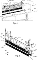
figure 5 shows, in perspective view and in detail, a pressure member of said working unit, in which the air protection and cleaning unit comprises a first and a second partitioning member in a respective operating position; -
figure 6 shows a side perspective view of the working unit, in which said first partitioning member is in a rest position and a protection member is in an operating position; -
figure 7A shows a rear side view of the pressure member offigure 5 , in which said first partitioning member is in a rest position; -
figure 7B shows a further rear side view of the pressure member offigure 5 , in which said first partitioning member is in an operating position; -
figure 8A shows a front side view of the pressure member offigure 5 , in which said second partitioning member is in an operating position; -
figure 8B shows a rear side view of the pressure member offigure 5 , in which said first partitioning member is in an operating position; and -
figure 9 shows a block diagram of an embodiment of the method of cleaning the air, according to the present invention. - In the various figures, similar parts will be indicated with the same numerical references.
- With reference to
figure 1 , the machine for working pieces, such as panels P made of wood, glass, fiberglass, plastic, and the like, globally indicated with the reference letter M, substantially comprises an entry/exit or loading/unloading station M1 of said panels P, a workingunit 1 to perform a respective working on said panels P, a loading or supplying plane M2, opposite to said entry/exit station M1, a pushing group G, movable on said loading plane M2 and capable of moving the panels P towards the workingunit 1 by means of one or more gripping members G1, such as a gripper and the like, and a logic control unit UM, connected to said workingunit 1 and to said pusher group G. - However, in other embodiments of the present invention, said machine M may not comprise the loading plane M2 and said pushing group G.
- Furthermore, in the embodiment that is describes, the machine M is a cutting machine. However, the machine M can be a machine of a different type, without thereby departing from the scope of protection of the present invention.
- The working
unit 1 develops along a first X-axis of a Cartesian reference system XYZ shown infigures 1 -5B, and substantially carries out cuts on the panels P along a cutting line T, parallel or substantially parallel to said first X-axis. - In the embodiment that is described, there is a working
unit 1. However, in other embodiments, two or moreworking units 1 may be present. - In particular, as can be seen from
figures 2 and4 , workingunit 1 comprises a workingplane 10 and alocking member 11, such as apressure member 11 and the like, arranged above said workingplane 10. - The working
plane 10, which extends along said first X-axis, allows the support of the panels P to be worked. - The
pressure member 11, on the other hand, extends along said first X-axis and is movable along a third Z-axis, vertical and orthogonal with respect to said first X-axis, between a rest position, in which saidpressure member 11 is raised with respect to said workingplane 10, and a working position, in which saidpressure member 11 is approaching with respect to said workingplane 10, in such a way as to block the panels P to be worked between said workingplane 10 and thesame pressure member 11. - With particular reference to
figures 4-5 and7A-8B , as will be explained better below, thepressure member 11 comprises a first support orfirst beam 145A arranged on a first side of saidpressure member 11 and a second support orsecond beam 145B arranged on the opposite side of saidpressure member 11, and movingmeans 146 arranged at the ends of saidpressure member 11. - More in detail, as will be better described hereinafter, said moving
means 146 such as, for example, pneumatic cylinders and the like, move said supports 145A, 145B along said third Z-axis from a first position or raised position to a second position or lowered position, with respect to said workingplane 10. - Furthermore, as can be seen from
figure 2 , the workingunit 1 comprises a workinggroup 12, which in turn comprises at least oneworking tool plane 10. - In the present embodiment, said
working group 12 is acutting group 12 comprising a first disc orcircular blade 120 and a secondcircular disc blade 121. - In particular, said
disc blades first disc blade 120 is used to carry out at least one incision on each panel P, while saidsecond disc blade 121 is used to cut each panel P in a known way. - However, in other embodiments, the number and type of the
working group 12 can be different from what is described. - In particular, the cutting takes place thanks to the displacement of said
cutting group 12 in a working zone T. - In the embodiment that is described, the working zone T is a cutting line T. However, in other embodiments of the present invention, the cutting zone T can be different from what has been described, such as, for example, a point for drilling or a circumscribed zone for a related machining.
- Furthermore, the working
tool 12 is vertically movable between a rest position, in which it is arranged below the workingplane 10, laterally at one end of said cutting line T, and a working position, in which it is arranged at least partially protruding with respect to said workingplane 10. - More specifically, the working
tool 12 lies on a plane XZ defined by the first X-axis and the third Z-axis, protruding from said workingplane 10, in its working position, through aslot 13 for a given portion, so as to cut each panel P along the cutting line T. - Furthermore, the working
tool 12 is rotatable around a rotation axis orthogonal to the aforementioned plane XZ and, therefore, parallel to said second Y-axis, in turn orthogonal to said first X and third Z axis. - The working
unit 1 comprises moving means (not shown in the figures) capable of rotating said workingtool 12 around its own rotation axis. - Furthermore, the working
unit 1 comprises a group for protecting and cleaning the air 14 to clean and filter the air surrounding the working tool. - Said group for protecting and cleaning the air 14 comprises a
first partitioning member 140A, asecond partitioning member 140B parallel or substantially parallel to saidfirst partitioning member 140A, an air inlet device orblower device 142, and twosuction devices - In particular, as will be better described hereinafter, said
partitioning members pressure member 11 and connected to saidrelevant supports - Furthermore, said
partitioning members - With particular reference to
figures 1-8B , in the present embodiment, thefirst partitioning member 140A comprises a first plurality ofstrips 140A all arranged side by side to form a first wall orpartition 140A and movable alongrelevant guides 141A, between a first position or rest position, and a second position or operating position and vice versa. - Similarly, the
second partitioning member 140B comprises a second plurality ofstrips 140B all arranged side by side to form a second wall orpartition 140B, and movable alongrelevant guides 141B between said first position or rest position, and said second position or operating position and vice versa. - However, in other embodiments of the present invention, the type and arrangement of said
partitioning members member - In particular, said
first partition 140A can slide along therelevant guide 141A, obtained on a first side of saidpressure member 11, between said rest position, in which it is at least partially raised with respect to the workingplane 10, and said operating position, in which it contacts said panel P and/or said workingplane 10. - Similarly, said
second partition 140B can slide along therelevant guide 141B, obtained on a second side of saidpressure member 11, opposite to said first side, between said rest position, in which it is at least partially raised with respect to the workingplane 10, and said operating position, in which it contacts said panel P and/or said workingplane 10. - In particular, when each
partition partition plane 10. - Each
partition plane 10. - As anticipated, the movement of each
support partition - In fact, each strip of said
partitions relevant support partitions plane 10 while some other strips of saidpartitions partition - More in detail, with particular reference to
figure 7A , when eachpartition pressure member 11, by an operator or a mechanical arm, for example, to pick up the panel P worked by said workingtool 12 to carry out any subsequent ones. - When, on the other hand, each
partition - Therefore, when each
partition first partition 140A and saidsecond partition 140B. - As can be seen from
figures 3 and6 , the workingunit 1 then comprises aprotection member 15 arranged externally to the volume V defined between saidfirst partition 140A and saidsecond partition 140B, on the side of the loading/unloading station M1, and having one end connected to said lockingmember 11. - In particular, said
protection member 15 is capable of avoiding, when in use, the contact between the workingtool 12 and the operator, and the leakage of parts of said panel P from said machine M. - In the present embodiment, the
protection member 15 comprises a plurality ofstrips 15, all arranged side by side and parallel to each other and movable between an operating position, in which they are arranged substantially perpendicular to said workingplane 10, avoiding, for example, the leakage of pieces of each panel P, and a rest position, in which they are raised with respect to said workingplane 10, allowing the entry or exit of pieces or panels P from said workingunit 1. - However, in other embodiments of the present invention, the
protection member 15 can be different from what is described, for example, it can be made by means of a single element. - The
blower device 142 is arranged in correspondence with the cutting line T, in proximity to afirst end 110 of saidpressure member 11. - In particular, said
blower device 142 is connected to said workingunit 1 and to said logic control unit UM. - In the embodiment that is described, said
blower device 142 is an ionizer. However, in other embodiments of the present invention, the position and the type of saidblower device 142 may be different from what has been described. - Therefore, said
blower device 142 is capable of introducing an ionized air flow within said volume V, in order to reduce or neutralize the electrostatic charges generated during the working of the panel P. - The
blower device 142 comprises a relevant motor (not shown in the figures) capable of starting the introduction of ionized air. - The
suction devices first suction device 143 arranged in correspondence with the cutting line T, in proximity to asecond end 120 of saidpressure member 11, and asecond suction device 144, also arranged in correspondence with the cutting line T, above saidpartitioning members protection member 15. - In particular, each
suction device unit 1 and to said logic control unit UM. - These suction devices 143,144 are capable of sucking the air as well as the materials coming from the working of said panel P present within said volume V, so as to clean the area around the panel P during the working of the same panel P.
- The suction devices 143,144 comprise relevant motors (not shown in the figures) capable of starting the suction of air and residual materials.
- The logic control unit UM of said machine M, connected to said
blower device 142 and to saidsuction devices devices - Furthermore, the logic control unit UM of said machine M, is operatively connected to said
partitions partition - The operation of the
method 2 of cleaning the air surrounding a workingtool 12 of a machine M for working wooden pieces and the like, schematically shown infigure 9 , is as follows. - Initially, when it is intended to carry out a working on at least one panel P, the panel P to be worked is arranged, manually or automatically, in said loading station (not shown in the figures).
- Subsequently, in the
positioning step 20, said panel P is transported towards said workingunit 1, and, in particular, arranged on the workingplane 10, in correspondence with the workingtool 12. - Later, in the locking
step 21, thepressure member 11 is positioned in the relevant working position to lock the panel P to be worked between thesame pressure member 11, and the underlying workingplane 10. - Then, during the
closing step 22, thefirst partition 140A and thesecond partition 140B are positioned, by means of said moving means 145, in the relevant operating position, so as to contact said panel P and/or said workingplane 10 and therefore define the volume V around the cutting line T, into which ionized air can be introduced. - Once the panel P is locked in position, in the working
step 23, the panel P is worked by means of the workingtool 12. - Subsequently, in the
air injecting step 24, as it can be seen, in particular, fromfigure 6 , during the working of the panel P, ionized air is introduced by theblower device 142 inside the volume V delimited, as said, by thefirst partition 140A and by thesecond partition 140B around the cutting line T. - More in detail, the ionized air flow, as shown by the directional indicators of
figure 6 , proceeds, in the volume V, from theend 110 of thepressure member 11 towards theother end 120 of thesame pressure member 11. - Therefore, the electrostatic charges generated during the working of the panel P are neutralized by the ionized air flow emitted by the blower device 141, preventing any inflammation of dust or residual materials from the working.
- Following the working of the panel P, in the sucking
step 25, the suction devices 143,144 suck the air in the volume V as well as the residual materials of the working of the panel P. - In the
opening phase 26, thefirst partition 140A and thesecond partition 140B are positioned, by means of said moving means 145, in the relevant rest position, so as to be at least partially raised with respect to the workingplane 10. - In addition, in the releasing
step 27, thepressure member 11 is positioned in the relevant raised position in order to release the worked panel P. - Finally, in the picking up
step 28, the worked panel P is picked up by the operator or by a picking device, such as a robot. - A first advantage of the air protection and cleaning unit, according to the present invention, is that of neutralizing the electrostatic charges generated during the working of the piece, avoiding the consequent formation of electrostatic discharges around the piece to be worked.
- A further advantage of the air protection and cleaning unit, according to the present invention, is that of removing the residual materials of the working of the piece, minimizing the possibility of obstructing the air passageways around the piece to be worked.
- A further advantage of the air protection and cleaning unit, according to the present invention, is that of eliminating machine downtime due to obstructions of the suction walls.
- The present invention has been described for illustrative but not limitative purposes, according to its preferred embodiments, but it is to be understood that modifications and/or changes can be introduced by those skilled in the art without departing from the relevant scope as defined in the enclosed claims.
Claims (13)
- Machine (M) for working panels (P) made of wood and the like, comprising:a working plane (10) for supporting at least one panel (P) to be worked;a working unit (1) comprisingat least one working tool (120, 121), for performing a working on said at least one panel (P) along a working zone (T), anda group (14) for protecting and cleaning the air surrounding the working tool (120, 121) during the working of said at least one panel (P), comprisinga first (140A) and a second (140B) partitioning member, wherein each partitioning member (140A, 140B) is movable between a rest position and an operating position such that, when said partitioning members (140A, 140B) are in said operating position, they define a volume (V) around said working tool (12), andan air inlet device (142) arranged in correspondence of said operating tool (120, 121), for injecting an air flow into said volume (V),wherein said machine (M) is characterized in that said air flow injected by air inlet device (142) of said group (14) for protecting and cleaning the air is an ionized air flow for reducing or neutralizing electrostatic charges generated during the working of said at least one panel (P).
- Machine (M) according to the preceding claim, characterized in that said group (14) for protecting and cleaning the air comprises a first suction device (143) arranged in correspondence of said working zone (T),
wherein said first suction device (143) is capable of sucking the air and materials and waste resulting from the working of said at least one panel (P) which are present within said volume (V), so as to clean the zone around said at least one panel (P) during working. - Machine (M) according to any one of the preceding claims, characterized in that said group (14) for protecting and cleaning the air comprises a second suction device (144), arranged in correspondence of said working zone (T), above said first (140A) and second (140B) partitioning members,
wherein said second suction device (144) is capable of sucking the air and materials and waste resulting from the working of said at least one panel (P) which are present within said volume (V), so as to clean the zone around said at least one panel (P) during working. - Machine (M) according to any one of the preceding claims, characterizedin that said first partitioning member (140A) is a first partition (140A) movable between said rest position, wherein it is at least partially raised with respect to said working plane (10), and said operating position, wherein it touches said at least one panel (P) and/or said working plane (10) and vice versa, andin that said second partitioning member (140B) is a second partition (140B) movable between said rest position, wherein it is at least partially raised with respect to said working plane (10), and said operating position, wherein it touches said at least one panel (P) and/or said working plane (10) and vice versa.
- Machine (M) according to the preceding claim, characterizedin that said first partition (140A) is made of a first plurality of strips (140A) arranged all side by side and movable along relevant guides (141A) between said rest position and said operating position and vice versa, andin that said second partition (140B) is made of a second plurality of strips (140B) arranged all side by side and movable along relevant guides (141B) between said rest position and said operating position and vice versa,such that, when in said operating position, each partition (140A, 140B) is capable of adapting itself to the section of the panel (P) arranged on said working plane (10).
- Machine (M) according to any one of claims 2-5, characterizedin that it comprises a locking member (11) for locking said at least one panel (P) during working,in that each partitioning member (140A, 140B) is connected to said locking member (11),in that said air inlet device (142) is arranged in proximity to a first end (110) of said locking member (11), andin that said first suction device (143) is arranged in proximity to a second end (120) of said locking member (11).
- Machine (M) according to the preceding claim, characterized in that said locking member (11) comprisesa first support (145A) arranged on one side of said locking member (11), wherein said support (145A) is connected to said first partition (140A),a second support (145B) arranged on the other side of said locking member (11), wherein said second support (145B) is connected to said second partition (140B), andmoving means (146) for moving said supports (145A, 145B), so as to move said relevant partition (140A, 140B) from said rest position to said operating position and vice versa.
- Machine (M) according to the preceding claim, characterized in that it comprises a first guide (141A) obtained on a first side of said locking member (11) and a second guide (141B) obtained on a second side of said locking member (11), wherein said second side is opposite to said first side,wherein said first partition (140A) is slidingly movable along said first guide (141A), with a direction perpendicular or substantially perpendicular to said working plane (10), andwherein said second partition (140B) is slidingly movable along said second guide (141b), with said direction perpendicular or substantially perpendicular to said working plane (10).
- Machine (M) according to any one of claims 6-8, characterized in that said locking member (11) is arranged above said working plane (10) and movable between a rest position, in which said locking member (11) is raised with respect to said working plane (10), and a working position, wherein said locking member (11) locks said at least one panel (P) to be worked on said working plane (10).
- Machine (M) according to any one of the preceding claims, characterized in that said machine (M) is a cutting machine,wherein said at least one working tool (120, 121) comprises a first circular blade (120) and a second circular blade (121), andwherein said working zone (T) is a cutting line (T), such that said first circular blade (120) makes at least one incision on said panel (P) and that said second circular blade (121) cuts each panel (P) along said cutting line (T).
- Method (2) for cleaning the air surrounding a working tool (120,121) of a machine (M) for working panels (P) made of wood and the like of the type comprisinga working plane (10) for supporting at least one panel (P) to be worked,at least one working tool (120, 121) for performing a working on said at least one panel (P) along a working zone (T),wherein said method (2) comprises the following steps:- positioning (20) at least one panel (P) on said working plane (10), in correspondence with said working tool (120, 121);- positioning (22) each partitioning member (140A, 140B) in the relevant operating position in such a way that said partitioning members (140A, 140B) define a volume (V) around said working tool (120, 121);- performing (23), by means of said working tool (120, 121), a working of said at least one panel (P); and- injecting (24), by means of said air inlet device (142), a flow of ionized air into said volume (V) for neutralizing electrostatic charges generated during the working of said at least one panel (P).
- Method (2) according to the preceding claim, characterized in that it comprises, following said air injecting step (24), the further step of sucking (25), by means of a first suction device (143) and a second suction device (144), the air present within said volume (V) as well as the residual materials from the working of said at least one panel (P).
- Method (2) according to any one of claims 11 o 12, characterizedin that said machine (M) further comprises a locking member (11) for locking said at least one panel (P) during working, andin that it comprises, following said positioning step (20), the further step of locking (21), by means of said locking member (11), said at least one panel (P) on said working plane (10).
Applications Claiming Priority (1)
| Application Number | Priority Date | Filing Date | Title |
|---|---|---|---|
| IT102021000011360A IT202100011360A1 (en) | 2021-05-04 | 2021-05-04 | Improved Machine for Working Wood Workpieces, Air Protection and Cleaning Assembly, and Method for Cleaning the Air. |
Publications (2)
| Publication Number | Publication Date |
|---|---|
| EP4086053A1 true EP4086053A1 (en) | 2022-11-09 |
| EP4086053B1 EP4086053B1 (en) | 2025-09-24 |
Family
ID=77227001
Family Applications (1)
| Application Number | Title | Priority Date | Filing Date |
|---|---|---|---|
| EP22170790.4A Active EP4086053B1 (en) | 2021-05-04 | 2022-04-29 | Improved machine for working panels made of wood, group for protecting and cleaning the air and method for cleaning the air |
Country Status (2)
| Country | Link |
|---|---|
| EP (1) | EP4086053B1 (en) |
| IT (1) | IT202100011360A1 (en) |
Cited By (1)
| Publication number | Priority date | Publication date | Assignee | Title |
|---|---|---|---|---|
| IT202300017826A1 (en) * | 2023-08-30 | 2025-03-02 | Scm Group Spa | METHOD FOR ADJUSTING THE SUCTION FLOW RATE OF A WOODWORKING MACHINE |
Citations (3)
| Publication number | Priority date | Publication date | Assignee | Title |
|---|---|---|---|---|
| JPS62284731A (en) * | 1986-06-04 | 1987-12-10 | Fujitsu Ltd | Resin machining device |
| EP1875994A1 (en) * | 2006-07-07 | 2008-01-09 | SCM GROUP S.p.A. | Machine tool |
| CN108032385A (en) * | 2018-01-05 | 2018-05-15 | 东北林业大学 | A kind of negative oxygen ion pre-processes formula wood-based plate loading bay |
-
2021
- 2021-05-04 IT IT102021000011360A patent/IT202100011360A1/en unknown
-
2022
- 2022-04-29 EP EP22170790.4A patent/EP4086053B1/en active Active
Patent Citations (3)
| Publication number | Priority date | Publication date | Assignee | Title |
|---|---|---|---|---|
| JPS62284731A (en) * | 1986-06-04 | 1987-12-10 | Fujitsu Ltd | Resin machining device |
| EP1875994A1 (en) * | 2006-07-07 | 2008-01-09 | SCM GROUP S.p.A. | Machine tool |
| CN108032385A (en) * | 2018-01-05 | 2018-05-15 | 东北林业大学 | A kind of negative oxygen ion pre-processes formula wood-based plate loading bay |
Cited By (2)
| Publication number | Priority date | Publication date | Assignee | Title |
|---|---|---|---|---|
| IT202300017826A1 (en) * | 2023-08-30 | 2025-03-02 | Scm Group Spa | METHOD FOR ADJUSTING THE SUCTION FLOW RATE OF A WOODWORKING MACHINE |
| EP4516471A1 (en) * | 2023-08-30 | 2025-03-05 | SCM Group S.p.A. | Method for regulating a negative pressure flow rate in a woodworking machine |
Also Published As
| Publication number | Publication date |
|---|---|
| IT202100011360A1 (en) | 2022-11-04 |
| EP4086053B1 (en) | 2025-09-24 |
Similar Documents
| Publication | Publication Date | Title |
|---|---|---|
| EP4086053B1 (en) | Improved machine for working panels made of wood, group for protecting and cleaning the air and method for cleaning the air | |
| KR100909727B1 (en) | Wafer transfer device and substrate transfer device | |
| JP6716756B1 (en) | Machine Tools | |
| EP4032671A1 (en) | Method for picking up a panel from the exit station of a machine for working panels made of wood and the like and machine thereof | |
| CN101670535A (en) | Processing machine | |
| CN107107378A (en) | The automatic machine tool and method for the glass plate arranged vertically for automatic drilling and milling | |
| EP0603438B1 (en) | Suction tables for a numerical control router | |
| US7021323B1 (en) | Dust-incompatible article transfer container cleaner | |
| US11768475B2 (en) | Machine for working glass slabs with a computerized numeric control assembly and related production process | |
| US20030167102A1 (en) | Valve/sensor assemblies | |
| EP0605940B1 (en) | Numerical control routers with press and/or suction capabilities | |
| KR20220001230A (en) | Automatic cutting apparatus for pvc windows and doors | |
| KR20060028225A (en) | Chip processing system for large machine tools | |
| CN119973717B (en) | Numerical control machine tool with safety limiting mechanism | |
| KR101909973B1 (en) | A robotic system capable of loading and unloading processing equipment in a two-story storage space | |
| US5486746A (en) | Positioning rule stopper apparatus in a numerical control router | |
| EP3808500B1 (en) | Chips shielding device for a working assembly and working machine comprising the device | |
| EP3895841A1 (en) | Machine to process components made of wood or the like | |
| CN221247888U (en) | Anti-collision tool changing magazine | |
| US20210370436A1 (en) | Machine for working wooden workpieces comprising a laser system and operation method thereof | |
| EP4606516A1 (en) | Machine for machining wood | |
| EP3795293B1 (en) | Positioning and blocking device for positioning and blocking workpieces with respect to a working table | |
| KR100628580B1 (en) | Production system | |
| US20120255648A1 (en) | Log Chipper with Log Jam Clearing Feature | |
| CN217019572U (en) | Automatic drilling machine |
Legal Events
| Date | Code | Title | Description |
|---|---|---|---|
| PUAI | Public reference made under article 153(3) epc to a published international application that has entered the european phase |
Free format text: ORIGINAL CODE: 0009012 |
|
| STAA | Information on the status of an ep patent application or granted ep patent |
Free format text: STATUS: THE APPLICATION HAS BEEN PUBLISHED |
|
| AK | Designated contracting states |
Kind code of ref document: A1 Designated state(s): AL AT BE BG CH CY CZ DE DK EE ES FI FR GB GR HR HU IE IS IT LI LT LU LV MC MK MT NL NO PL PT RO RS SE SI SK SM TR |
|
| STAA | Information on the status of an ep patent application or granted ep patent |
Free format text: STATUS: REQUEST FOR EXAMINATION WAS MADE |
|
| 17P | Request for examination filed |
Effective date: 20230509 |
|
| RBV | Designated contracting states (corrected) |
Designated state(s): AL AT BE BG CH CY CZ DE DK EE ES FI FR GB GR HR HU IE IS IT LI LT LU LV MC MK MT NL NO PL PT RO RS SE SI SK SM TR |
|
| P01 | Opt-out of the competence of the unified patent court (upc) registered |
Effective date: 20230518 |
|
| RIC1 | Information provided on ipc code assigned before grant |
Ipc: B27D 5/00 20060101ALI20250314BHEP Ipc: B27M 1/08 20060101AFI20250314BHEP |
|
| GRAP | Despatch of communication of intention to grant a patent |
Free format text: ORIGINAL CODE: EPIDOSNIGR1 |
|
| STAA | Information on the status of an ep patent application or granted ep patent |
Free format text: STATUS: GRANT OF PATENT IS INTENDED |
|
| INTG | Intention to grant announced |
Effective date: 20250502 |
|
| GRAS | Grant fee paid |
Free format text: ORIGINAL CODE: EPIDOSNIGR3 |
|
| GRAA | (expected) grant |
Free format text: ORIGINAL CODE: 0009210 |
|
| STAA | Information on the status of an ep patent application or granted ep patent |
Free format text: STATUS: THE PATENT HAS BEEN GRANTED |
|
| AK | Designated contracting states |
Kind code of ref document: B1 Designated state(s): AL AT BE BG CH CY CZ DE DK EE ES FI FR GB GR HR HU IE IS IT LI LT LU LV MC MK MT NL NO PL PT RO RS SE SI SK SM TR |
|
| REG | Reference to a national code |
Ref country code: GB Ref legal event code: FG4D |
|
| REG | Reference to a national code |
Ref country code: CH Ref legal event code: EP |
|
| REG | Reference to a national code |
Ref country code: DE Ref legal event code: R096 Ref document number: 602022021824 Country of ref document: DE |
|
| REG | Reference to a national code |
Ref country code: IE Ref legal event code: FG4D |
|
| PG25 | Lapsed in a contracting state [announced via postgrant information from national office to epo] |
Ref country code: NO Free format text: LAPSE BECAUSE OF FAILURE TO SUBMIT A TRANSLATION OF THE DESCRIPTION OR TO PAY THE FEE WITHIN THE PRESCRIBED TIME-LIMIT Effective date: 20251224 |
|
| REG | Reference to a national code |
Ref country code: LT Ref legal event code: MG9D |
|
| PG25 | Lapsed in a contracting state [announced via postgrant information from national office to epo] |
Ref country code: FI Free format text: LAPSE BECAUSE OF FAILURE TO SUBMIT A TRANSLATION OF THE DESCRIPTION OR TO PAY THE FEE WITHIN THE PRESCRIBED TIME-LIMIT Effective date: 20250924 |
|
| PG25 | Lapsed in a contracting state [announced via postgrant information from national office to epo] |
Ref country code: HR Free format text: LAPSE BECAUSE OF FAILURE TO SUBMIT A TRANSLATION OF THE DESCRIPTION OR TO PAY THE FEE WITHIN THE PRESCRIBED TIME-LIMIT Effective date: 20250924 |
|
| PG25 | Lapsed in a contracting state [announced via postgrant information from national office to epo] |
Ref country code: GR Free format text: LAPSE BECAUSE OF FAILURE TO SUBMIT A TRANSLATION OF THE DESCRIPTION OR TO PAY THE FEE WITHIN THE PRESCRIBED TIME-LIMIT Effective date: 20251225 |
|
| PG25 | Lapsed in a contracting state [announced via postgrant information from national office to epo] |
Ref country code: SE Free format text: LAPSE BECAUSE OF FAILURE TO SUBMIT A TRANSLATION OF THE DESCRIPTION OR TO PAY THE FEE WITHIN THE PRESCRIBED TIME-LIMIT Effective date: 20250924 |
|
| PG25 | Lapsed in a contracting state [announced via postgrant information from national office to epo] |
Ref country code: LV Free format text: LAPSE BECAUSE OF FAILURE TO SUBMIT A TRANSLATION OF THE DESCRIPTION OR TO PAY THE FEE WITHIN THE PRESCRIBED TIME-LIMIT Effective date: 20250924 |
|
| PG25 | Lapsed in a contracting state [announced via postgrant information from national office to epo] |
Ref country code: BG Free format text: LAPSE BECAUSE OF FAILURE TO SUBMIT A TRANSLATION OF THE DESCRIPTION OR TO PAY THE FEE WITHIN THE PRESCRIBED TIME-LIMIT Effective date: 20250924 |
|
| PG25 | Lapsed in a contracting state [announced via postgrant information from national office to epo] |
Ref country code: RS Free format text: LAPSE BECAUSE OF FAILURE TO SUBMIT A TRANSLATION OF THE DESCRIPTION OR TO PAY THE FEE WITHIN THE PRESCRIBED TIME-LIMIT Effective date: 20251224 |
|
| REG | Reference to a national code |
Ref country code: NL Ref legal event code: MP Effective date: 20250924 |
|
| PG25 | Lapsed in a contracting state [announced via postgrant information from national office to epo] |
Ref country code: NL Free format text: LAPSE BECAUSE OF FAILURE TO SUBMIT A TRANSLATION OF THE DESCRIPTION OR TO PAY THE FEE WITHIN THE PRESCRIBED TIME-LIMIT Effective date: 20250924 |
|
| PG25 | Lapsed in a contracting state [announced via postgrant information from national office to epo] |
Ref country code: SM Free format text: LAPSE BECAUSE OF FAILURE TO SUBMIT A TRANSLATION OF THE DESCRIPTION OR TO PAY THE FEE WITHIN THE PRESCRIBED TIME-LIMIT Effective date: 20250924 |
|
| PG25 | Lapsed in a contracting state [announced via postgrant information from national office to epo] |
Ref country code: ES Free format text: LAPSE BECAUSE OF FAILURE TO SUBMIT A TRANSLATION OF THE DESCRIPTION OR TO PAY THE FEE WITHIN THE PRESCRIBED TIME-LIMIT Effective date: 20250924 |
|
| PGFP | Annual fee paid to national office [announced via postgrant information from national office to epo] |
Ref country code: IT Payment date: 20260206 Year of fee payment: 5 |
|
| PG25 | Lapsed in a contracting state [announced via postgrant information from national office to epo] |
Ref country code: IS Free format text: LAPSE BECAUSE OF FAILURE TO SUBMIT A TRANSLATION OF THE DESCRIPTION OR TO PAY THE FEE WITHIN THE PRESCRIBED TIME-LIMIT Effective date: 20260124 |
|
| PG25 | Lapsed in a contracting state [announced via postgrant information from national office to epo] |
Ref country code: PT Free format text: LAPSE BECAUSE OF FAILURE TO SUBMIT A TRANSLATION OF THE DESCRIPTION OR TO PAY THE FEE WITHIN THE PRESCRIBED TIME-LIMIT Effective date: 20260126 Ref country code: CZ Free format text: LAPSE BECAUSE OF FAILURE TO SUBMIT A TRANSLATION OF THE DESCRIPTION OR TO PAY THE FEE WITHIN THE PRESCRIBED TIME-LIMIT Effective date: 20250924 |
|
| PG25 | Lapsed in a contracting state [announced via postgrant information from national office to epo] |
Ref country code: PL Free format text: LAPSE BECAUSE OF FAILURE TO SUBMIT A TRANSLATION OF THE DESCRIPTION OR TO PAY THE FEE WITHIN THE PRESCRIBED TIME-LIMIT Effective date: 20250924 |
|
| PG25 | Lapsed in a contracting state [announced via postgrant information from national office to epo] |
Ref country code: EE Free format text: LAPSE BECAUSE OF FAILURE TO SUBMIT A TRANSLATION OF THE DESCRIPTION OR TO PAY THE FEE WITHIN THE PRESCRIBED TIME-LIMIT Effective date: 20250924 Ref country code: SK Free format text: LAPSE BECAUSE OF FAILURE TO SUBMIT A TRANSLATION OF THE DESCRIPTION OR TO PAY THE FEE WITHIN THE PRESCRIBED TIME-LIMIT Effective date: 20250924 |