EP4085956A1 - Backup flow control system and method applicable to anesthesia machine - Google Patents
Backup flow control system and method applicable to anesthesia machine Download PDFInfo
- Publication number
- EP4085956A1 EP4085956A1 EP19958510.0A EP19958510A EP4085956A1 EP 4085956 A1 EP4085956 A1 EP 4085956A1 EP 19958510 A EP19958510 A EP 19958510A EP 4085956 A1 EP4085956 A1 EP 4085956A1
- Authority
- EP
- European Patent Office
- Prior art keywords
- controller
- control system
- flow control
- electromagnet
- backup
- Prior art date
- Legal status (The legal status is an assumption and is not a legal conclusion. Google has not performed a legal analysis and makes no representation as to the accuracy of the status listed.)
- Granted
Links
Images


Classifications
-
- A—HUMAN NECESSITIES
- A61—MEDICAL OR VETERINARY SCIENCE; HYGIENE
- A61M—DEVICES FOR INTRODUCING MEDIA INTO, OR ONTO, THE BODY; DEVICES FOR TRANSDUCING BODY MEDIA OR FOR TAKING MEDIA FROM THE BODY; DEVICES FOR PRODUCING OR ENDING SLEEP OR STUPOR
- A61M16/00—Devices for influencing the respiratory system of patients by gas treatment, e.g. ventilators; Tracheal tubes
- A61M16/021—Devices for influencing the respiratory system of patients by gas treatment, e.g. ventilators; Tracheal tubes operated by electrical means
- A61M16/022—Control means therefor
- A61M16/024—Control means therefor including calculation means, e.g. using a processor
-
- A—HUMAN NECESSITIES
- A61—MEDICAL OR VETERINARY SCIENCE; HYGIENE
- A61M—DEVICES FOR INTRODUCING MEDIA INTO, OR ONTO, THE BODY; DEVICES FOR TRANSDUCING BODY MEDIA OR FOR TAKING MEDIA FROM THE BODY; DEVICES FOR PRODUCING OR ENDING SLEEP OR STUPOR
- A61M16/00—Devices for influencing the respiratory system of patients by gas treatment, e.g. ventilators; Tracheal tubes
- A61M16/10—Preparation of respiratory gases or vapours
- A61M16/1005—Preparation of respiratory gases or vapours with O2 features or with parameter measurement
-
- A—HUMAN NECESSITIES
- A61—MEDICAL OR VETERINARY SCIENCE; HYGIENE
- A61M—DEVICES FOR INTRODUCING MEDIA INTO, OR ONTO, THE BODY; DEVICES FOR TRANSDUCING BODY MEDIA OR FOR TAKING MEDIA FROM THE BODY; DEVICES FOR PRODUCING OR ENDING SLEEP OR STUPOR
- A61M16/00—Devices for influencing the respiratory system of patients by gas treatment, e.g. ventilators; Tracheal tubes
- A61M16/10—Preparation of respiratory gases or vapours
- A61M16/104—Preparation of respiratory gases or vapours specially adapted for anaesthetics
-
- A—HUMAN NECESSITIES
- A61—MEDICAL OR VETERINARY SCIENCE; HYGIENE
- A61M—DEVICES FOR INTRODUCING MEDIA INTO, OR ONTO, THE BODY; DEVICES FOR TRANSDUCING BODY MEDIA OR FOR TAKING MEDIA FROM THE BODY; DEVICES FOR PRODUCING OR ENDING SLEEP OR STUPOR
- A61M16/00—Devices for influencing the respiratory system of patients by gas treatment, e.g. ventilators; Tracheal tubes
- A61M16/10—Preparation of respiratory gases or vapours
- A61M16/12—Preparation of respiratory gases or vapours by mixing different gases
- A61M16/122—Preparation of respiratory gases or vapours by mixing different gases with dilution
- A61M16/125—Diluting primary gas with ambient air
-
- A—HUMAN NECESSITIES
- A61—MEDICAL OR VETERINARY SCIENCE; HYGIENE
- A61M—DEVICES FOR INTRODUCING MEDIA INTO, OR ONTO, THE BODY; DEVICES FOR TRANSDUCING BODY MEDIA OR FOR TAKING MEDIA FROM THE BODY; DEVICES FOR PRODUCING OR ENDING SLEEP OR STUPOR
- A61M16/00—Devices for influencing the respiratory system of patients by gas treatment, e.g. ventilators; Tracheal tubes
- A61M16/01—Devices for influencing the respiratory system of patients by gas treatment, e.g. ventilators; Tracheal tubes specially adapted for anaesthetising
-
- A—HUMAN NECESSITIES
- A61—MEDICAL OR VETERINARY SCIENCE; HYGIENE
- A61M—DEVICES FOR INTRODUCING MEDIA INTO, OR ONTO, THE BODY; DEVICES FOR TRANSDUCING BODY MEDIA OR FOR TAKING MEDIA FROM THE BODY; DEVICES FOR PRODUCING OR ENDING SLEEP OR STUPOR
- A61M16/00—Devices for influencing the respiratory system of patients by gas treatment, e.g. ventilators; Tracheal tubes
- A61M16/10—Preparation of respiratory gases or vapours
- A61M16/105—Filters
- A61M16/106—Filters in a path
- A61M16/107—Filters in a path in the inspiratory path
-
- A—HUMAN NECESSITIES
- A61—MEDICAL OR VETERINARY SCIENCE; HYGIENE
- A61M—DEVICES FOR INTRODUCING MEDIA INTO, OR ONTO, THE BODY; DEVICES FOR TRANSDUCING BODY MEDIA OR FOR TAKING MEDIA FROM THE BODY; DEVICES FOR PRODUCING OR ENDING SLEEP OR STUPOR
- A61M16/00—Devices for influencing the respiratory system of patients by gas treatment, e.g. ventilators; Tracheal tubes
- A61M16/10—Preparation of respiratory gases or vapours
- A61M16/14—Preparation of respiratory gases or vapours by mixing different fluids, one of them being in a liquid phase
- A61M16/18—Vaporising devices for anaesthetic preparations
-
- A—HUMAN NECESSITIES
- A61—MEDICAL OR VETERINARY SCIENCE; HYGIENE
- A61M—DEVICES FOR INTRODUCING MEDIA INTO, OR ONTO, THE BODY; DEVICES FOR TRANSDUCING BODY MEDIA OR FOR TAKING MEDIA FROM THE BODY; DEVICES FOR PRODUCING OR ENDING SLEEP OR STUPOR
- A61M16/00—Devices for influencing the respiratory system of patients by gas treatment, e.g. ventilators; Tracheal tubes
- A61M16/20—Valves specially adapted to medical respiratory devices
- A61M16/201—Controlled valves
- A61M16/202—Controlled valves electrically actuated
-
- A—HUMAN NECESSITIES
- A61—MEDICAL OR VETERINARY SCIENCE; HYGIENE
- A61M—DEVICES FOR INTRODUCING MEDIA INTO, OR ONTO, THE BODY; DEVICES FOR TRANSDUCING BODY MEDIA OR FOR TAKING MEDIA FROM THE BODY; DEVICES FOR PRODUCING OR ENDING SLEEP OR STUPOR
- A61M16/00—Devices for influencing the respiratory system of patients by gas treatment, e.g. ventilators; Tracheal tubes
- A61M16/20—Valves specially adapted to medical respiratory devices
- A61M16/201—Controlled valves
- A61M16/202—Controlled valves electrically actuated
- A61M16/203—Proportional
-
- A—HUMAN NECESSITIES
- A61—MEDICAL OR VETERINARY SCIENCE; HYGIENE
- A61M—DEVICES FOR INTRODUCING MEDIA INTO, OR ONTO, THE BODY; DEVICES FOR TRANSDUCING BODY MEDIA OR FOR TAKING MEDIA FROM THE BODY; DEVICES FOR PRODUCING OR ENDING SLEEP OR STUPOR
- A61M16/00—Devices for influencing the respiratory system of patients by gas treatment, e.g. ventilators; Tracheal tubes
- A61M16/20—Valves specially adapted to medical respiratory devices
- A61M16/208—Non-controlled one-way valves, e.g. exhalation, check, pop-off non-rebreathing valves
-
- A—HUMAN NECESSITIES
- A61—MEDICAL OR VETERINARY SCIENCE; HYGIENE
- A61M—DEVICES FOR INTRODUCING MEDIA INTO, OR ONTO, THE BODY; DEVICES FOR TRANSDUCING BODY MEDIA OR FOR TAKING MEDIA FROM THE BODY; DEVICES FOR PRODUCING OR ENDING SLEEP OR STUPOR
- A61M16/00—Devices for influencing the respiratory system of patients by gas treatment, e.g. ventilators; Tracheal tubes
- A61M16/0003—Accessories therefor, e.g. sensors, vibrators, negative pressure
- A61M2016/0027—Accessories therefor, e.g. sensors, vibrators, negative pressure pressure meter
-
- A—HUMAN NECESSITIES
- A61—MEDICAL OR VETERINARY SCIENCE; HYGIENE
- A61M—DEVICES FOR INTRODUCING MEDIA INTO, OR ONTO, THE BODY; DEVICES FOR TRANSDUCING BODY MEDIA OR FOR TAKING MEDIA FROM THE BODY; DEVICES FOR PRODUCING OR ENDING SLEEP OR STUPOR
- A61M16/00—Devices for influencing the respiratory system of patients by gas treatment, e.g. ventilators; Tracheal tubes
- A61M16/0003—Accessories therefor, e.g. sensors, vibrators, negative pressure
- A61M2016/003—Accessories therefor, e.g. sensors, vibrators, negative pressure with a flowmeter
- A61M2016/0033—Accessories therefor, e.g. sensors, vibrators, negative pressure with a flowmeter electrical
-
- A—HUMAN NECESSITIES
- A61—MEDICAL OR VETERINARY SCIENCE; HYGIENE
- A61M—DEVICES FOR INTRODUCING MEDIA INTO, OR ONTO, THE BODY; DEVICES FOR TRANSDUCING BODY MEDIA OR FOR TAKING MEDIA FROM THE BODY; DEVICES FOR PRODUCING OR ENDING SLEEP OR STUPOR
- A61M2202/00—Special media to be introduced, removed or treated
- A61M2202/02—Gases
- A61M2202/0266—Nitrogen (N)
- A61M2202/0283—Nitrous oxide (N2O)
-
- A—HUMAN NECESSITIES
- A61—MEDICAL OR VETERINARY SCIENCE; HYGIENE
- A61M—DEVICES FOR INTRODUCING MEDIA INTO, OR ONTO, THE BODY; DEVICES FOR TRANSDUCING BODY MEDIA OR FOR TAKING MEDIA FROM THE BODY; DEVICES FOR PRODUCING OR ENDING SLEEP OR STUPOR
- A61M2205/00—General characteristics of the apparatus
- A61M2205/16—General characteristics of the apparatus with back-up system in case of failure
Definitions
- Embodiments of the disclosure relate to the technical field of medical devices, and more particularly, to a backup flow control system and method applicable to an anesthesia machine.
- Two ways to control a fresh gas flow of an anesthesia machine are provided, one is to use a mechanical needle valve to regulate the flow, and the other is to use an electronic flow control system to control the flow, namely, the system automatically controls a flow of a gas circuit valve so as to reach an artificially set target flow or oxygen concentration.
- the electronic flow control system due to its high accuracy of flow control, is widely applied in various types of anesthesia machines.
- the anesthesia machine may not provide oxygen for a patient. Therefore, in general, it is possible to configure a backup flow control system for the electronic flow control system of the anesthesia machine, so as to achieve emergency ventilation in case of the failure of the electronic flow control system and to improve safety.
- a needle valve for emergency regulation is directly exposed outside the anesthesia machine, which is prone to accidental regulation and influencing a patient's ventilation.
- a needle valve is hidden under a cover, and when emergency ventilation is required, the cover is opened for switching to emergency ventilation, and a flow is then regulated by using the needle valve; however, it may be difficult for medical care personnel to find the cover in an emergency state, resulting in a delay in treatment.
- a needle valve In a third type of backup flow control system, a needle valve is retracted inside an anesthesia machine, and when the electronic flow control system fails or is manually operated, the needle valve pops up for regulation, electronic control and manual control of popup and retraction of the needle valve need to be compatible, which resulting in a complicated structure. Therefore, the existing three types of backup flow control systems have low flexibility and reliability.
- embodiments of the disclosure are expected to provide a backup flow control system and method applicable to an anesthesia machine, which not only protects a flow regulation valve from accidental regulation by means of an openable cover, but also is simple in structure, and is capable of automatically opening the cover when backup ventilation is required, thereby improving flexibility and reliability.
- An embodiment of the disclosure provide a backup flow control system applicable to an anesthesia machine.
- the backup flow control system turns on a backup ventilation mode when an electronic flow control system of the anesthesia machine has failed, and the backup flow control system includes: a first controller, a flow regulation valve, an accommodation cavity and a cover,
- the above-mentioned system further includes an electromagnet and a permanent magnet, where power sources for the electromagnet and the electronic flow control system are different, one of the permanent magnet and the electromagnet is fixed to the cover and the other one thereof is fixed to the accommodation cavity, and the permanent magnet corresponds to the electromagnet in position; and the first controller is connected to the electromagnet and controls to energize and de-energize of the electromagnet.
- the operating state of the electronic flow control system include a failure state and a working state.
- the first controller controls to energize the electromagnet when the electronic flow control system is in the failure state, such that the magnetism generated by a magnetic pole at an end of the electromagnet close to the permanent magnet is the same as the magnetism at an end of the permanent magnet close to the electromagnet in order to separate the electromagnet from the permanent magnet, and controls to de-energize the electromagnet when the electronic flow system is in the working state.
- the failure state is at least one of: communication failure, valve failure, sensor failure, anesthesia machine power system failure and user interface failure of the electronic flow control system.
- the above-mentioned system further includes a position sensor
- the position sensor is at least one of: a hall sensor, a photoelectric coupling sensor and a position switch.
- the first controller controls to turn on the backup ventilation mode when it is detected that the electromagnet generates a separating induction current, and controls to turn off the backup ventilation mode when it is detected that the electromagnet generates an attracting induction current.
- the flow regulation valve regulates a flow of a gas delivered to a patient according to a received regulation operation, when the backup ventilation mode is turned on, and stores a basic flow therein, when the backup ventilation mode is turned off.
- the gas is oxygen, or oxygen and air.
- the above-mentioned system further includes a system switch,
- the above-mentioned system further includes a flow sensor, where the flow sensor is connected to the flow regulation valve and the first controller, so as to detect a flow through the flow regulation valve and to feedback the detected flow to the first controller.
- the above-mentioned system further includes a glass tube flow meter, where the glass tube flow meter is connected to the flow regulation valve, so as to display a gas flow regulated by the flow regulation valve, when the backup ventilation mode is turn.
- the above-mentioned system further includes a glass tube backlight
- power sources for the electromagnet and the glass tube backlight are different from a power source for the electronic flow control system.
- the first controller is also included in the electronic flow control system, and the first controller detects an operating state of the electronic flow control system.
- the electromagnet is energized and separated from the permanent magnet, when the first controller fails, thereby controlling to open the cover.
- the electronic flow control system includes a second controller
- the first controller determines that the operating state of the electronic flow control system is a failure state when the interruption of communication with the second controller is detected.
- An embodiment of the disclosure provides a backup flow control method applicable to an anesthesia machine, the anesthesia machine including an electronic flow control system, the method including:
- controlling, by the first controller, to turn on a backup ventilation mode and to open a cover that closes an accommodation cavity, or controlling, by the first controller, to turn off the backup ventilation mode according to the operating state of the electronic flow control system includes:
- the operating state of the electronic flow control system include a failure state and a working state
- controlling, by the first controller, to energize and de-energize an electromagnet according to the operating state of the electronic flow control system includes: controlling, by the first controller, to energize the electromagnet when the electronic flow control system is in the failure state, such that the magnetism generated by a magnetic pole at an end of the electromagnet close to the permanent magnet is the same as the magnetism generated by a magnetic pole at an end of the permanent magnet close to the electromagnet in order to separate the electromagnet from the permanent magnet, and controlling, by the first controller, to de-energize the electromagnet when the electronic flow control system is in the working state.
- the above-mentioned method further includes: controlling, by the first controller, to turn on the backup ventilation mode when a position sensor detects that the cover is opened.
- the above-mentioned method further includes: controlling, by the first controller, to turn on the backup ventilation mode when it is detected that the electromagnet generates a separating induction current, and controlling, by the first controller, to turn off the backup ventilation mode when it is detected that the electromagnet generates an attracting induction current.
- obtaining an operating state of the electronic flow control system by the first controller includes: detecting the operating state of the electronic flow control system by the first controller.
- the electronic flow control system includes a second controller, the first controller being connected to the second controller, and obtaining an operating state of the electronic flow control system by the first controller includes:
- obtaining an operating state of the electronic flow control system by the first controller further includes: determining, by the first controller, that the operating state of the electronic flow control system is a failure state when interruption of communication with the second controller is detected.
- An embodiment of the disclosure provide a backup flow control system applicable to an anesthesia machine.
- the backup flow control system turns on a backup ventilation mode when an electronic flow control system of the anesthesia machine has failed.
- the backup flow control system includes: a first controller, a flow regulation valve, an accommodation cavity and a cover, where the accommodation cavity is a hollow structure having an opening, the cover is connected to the opening of the accommodation cavity to close the opening, and the flow regulation valve is disposed inside the accommodation cavity; and the first controller, according to an operating state of the electronic flow control system, controls to turn on the backup ventilation mode and to open the cover, such that the opening opens to expose the flow regulation valve, or controls to turn off the backup ventilation mode.
- the backup flow control system provided by the embodiment of the disclosure not only protects the flow regulation valve from accidental regulation by the openable cover, but also has a simple structure, and is capable of automatically opening the cover when backup ventilation is required, thereby improving flexibility and reliability.
- FIG. 1 is a first schematic structural diagram of a backup flow control system applicable to an anesthesia machine according to an embodiment of the disclosure. As shown in FIG. 1 , the backup flow control system includes: a first controller 1, a flow regulation valve 2, an accommodation cavity 3 and a cover 4.
- the accommodation cavity 3 is a hollow structure having an opening
- the cover 4 is connected to the opening of the accommodation cavity 3 to close the opening
- the flow regulation valve is disposed inside the accommodation cavity.
- the first controller 1 controls to turn on a backup ventilation mode and to open the cover 4, such that the opening opens to expose the flow regulation valve 2; or controls to turn off the backup ventilation mode.
- first controllers 1 and one or more flow regulation valves 2 may be provided in this embodiment of the disclosure.
- the specific number of the first controllers 1 and the specific number of the flow regulation valves 2 may be set according to actual requirements, and are not limited in the embodiment of the disclosure.
- the flow regulation mode 2 may be specifically a mechanical needle valve configured to regulate a flow.
- the flow regulation valve 2 may also be other types of devices configured to achieve flow regulation, which are not limited in the embodiment of the disclosure.
- first controllers 1 may be provided in the embodiment of the disclosure.
- the plurality of first controllers 1 may monitor their operating states mutually, such that normal first controllers 1 may be used to turn on or off the backup ventilation mode in the event of failure of some of the first controllers 1.
- the specific number of the first controllers 1 may be set according to actual requirements, and is not limited in the embodiment of the disclosure.
- the first controller 1 may control opening and closing of the cover 4 according to the operating state of the electronic flow control system such that the cover may be automatically opened to facilitate an operation by a user when backup ventilation is required.
- the way in which the first controller 1 achieves control of the opening and closing of the cover is not limited in the embodiment of the disclosure.
- FIG. 2 is a second schematic structural diagram of a backup flow control system applicable to an anesthesia machine according to an embodiment of the disclosure.
- the backup flow ventilation system further includes an electromagnet 5 and a permanent magnet 6, where power sources for the electromagnet 5 and the electronic flow control system are different, one of the permanent magnet 6 and the electromagnet 5 is fixed to the cover 4, and the other one thereof is fixed to the accommodation cavity 3, and the permanent magnet 6 corresponds to the electromagnet 5 in position.
- the first controller 1 is connected to the electromagnet 5 to control to energize and de-energized of the electromagnet 5.
- one or more electromagnets 5 and one or more permanent magnets 6 may be provided in the embodiment of the disclosure.
- the specific number of the electromagnets 5 and the specific number of the permanent magnets 6 may be set according to actual requirements, and are not limited in the embodiment of the disclosure.
- the permanent magnet 6 it is preferable to fix the permanent magnet 6 to the cover 4 and fix the electromagnet 5 to the accommodation cavity 3, and the permanent magnet corresponds to the electromagnet in position, so as to facilitate the routing of the electromagnet 5.
- one of the electromagnet 5 and the permanent magnet 6 is fixed to the cover 4, the other is fixed to the accommodation cavity 3, and the electromagnet corresponds to the permanent magnet in position. Therefore, when the first controller 1 controls the electromagnet 5 to be separated from the permanent magnet 6, the accommodation cavity 3 may be separated from the cover 4 accordingly, such that the opening of the accommodation cavity 3 opens, and the user may operate the flow regulation valve 2 to control a flow. When the electromagnet 5 and the permanent magnet 6 are attracted to each other, it is possible to engage the accommodation cavity 3 with the cover 4 accordingly, such that the opening of the accommodation cavity 3 is closed, and the flow regulation valve 2 is enclosed inside the accommodation cavity 3.
- the cover 4 may be made of a transparent or translucent material, such that the user may know that the flow regulation valve 2 is disposed inside the accommodation cavity 3.
- the operating state of the electronic flow control system of the anesthesia machine includes a failure state in which the first controller 1 controls to energize the electromagnet 5, such that the magnetism generated by a magnetic pole at an end of the electromagnet 5 close to the permanent magnet 6 is the same as the magnet generated by a magnetic pole at an end of the permanent magnet 6 close to the electromagnet 5 in order to separate the electromagnet 5 from the permanent magnet 6, and a working state in which the first controller controls to be de-energize the electromagnet 5.
- the user may manually operate to push the cover 4 toward the opening of the accommodation cavity 3, such that the permanent magnet 6 may magnetize the electromagnet 5 when the cove approaches at a certain distance from the accommodation cavity, allowing the electromagnet 5 and the permanent magnet 6 to attract each other so as to close the opening of the accommodation cavity 3.
- the failure state of the electronic flow control system is at least one of: communication failure, valve failure, sensor failure, anesthesia machine power system failure and user interface failure of the electronic flow control system.
- failure states are a few exemplary failure states listed.
- the failure state may also include other failures that cause the electronic flow control system to fail to control a gas flow of the anesthesia machine, which are not limited in the embodiment of the disclosure.
- the working state of the electronic flow control system namely, a state in which the electronic flow control system normally controls a gas flow of an anesthesia machine, excludes the related failures included in the above-described failure states.
- the backup flow control system may, when the electronic flow control system fails, control to turn on the backup ventilation mode in time for operating the flow regulation valve 2 by a user, ensuring the safety of the patient.
- FIG. 3 is a third schematic structural diagram of an electronic flow control system according to an embodiment of the disclosure.
- the backup flow control system may further include a position sensor 7, where the position sensor 7 is connected to the first controller 1 and is fixed to the cover 4 or the accommodation cavity 3.
- the first controller 1 controls to turn on the backup ventilation mode when the position sensor 7 detects that the cover 4 is open.
- the position sensor 7 is fixed to the cover 4, of course, may be actually fixed to the accommodation cavity 3, which is not limited in the embodiment of the disclosure.
- the position sensor 7 is at least one of: a hall sensor, a photoelectric coupling sensor and a position switch.
- the position sensor 7 may also be other devices configured to achieve position detection, and may be selected according to actual requirements, which is not limited in the embodiment of the disclosure.
- one or more position sensors 7 may be provided in the embodiment of the disclosure. With a plurality of position sensors 7, a problem that a single position sensor 7 fails and therefore the position of the cover 4 cannot be detected may be prevented.
- the specific number of the position sensors 7 may be selected according to actual requirements, and is not limited in the embodiment of the disclosure.
- the failure state such as the anesthesia machine power system failure or the user interface failure, for example, a failure such as a blank screen of a display screen
- the failure state such as the anesthesia machine power system failure or the user interface failure, for example, a failure such as a blank screen of a display screen
- the position sensor 7 thus detects that the cover 4 is in the opened position, and the user controls to turn on the backup ventilation mode and then can repair or replace relevant devices.
- the first controller 1 is further configured to control to turn on the backup ventilation mode when detecting that the electromagnet 5 generates a separating induction current, and to control to turn off the backup ventilation mode when detecting that the electromagnet 5 generates an attracting induction current.
- the backup flow control system may also include no position sensor 7 for detecting the position of the cover 4.
- the electromagnet 5 When the cover 4 is opened or closed, the electromagnet 5 will generate a corresponding induction current, such that whether the cover 4 is open or close may be determined, and the on or off of the backup ventilation mode may be controlled.
- the flow regulation valve 2 when the backup ventilation mode is turned on, regulates a flow of a gas delivered to the patient according to a received regulation operation, and when the backup ventilation mode is turned off, stores a basic flow therein.
- the gas controlled by the flow regulation valve 2 is oxygen or oxygen and air.
- control of oxygen is preferably applied to avoid hypoxia of the patient, and when a plurality of flow regulation valves 2 are disposed inside the accommodation cavity 3, respective control of flows of a plurality of types of gases may be achieved.
- the flow regulation valve 2 may store the basic flow when the backup ventilation mode is turned off, such that when the backup ventilation mode is controlled to be turned on next time, the basic flow may be supplied to the patient, avoiding the hypoxia of the patient due to the fact that the user does not operate the flow regulation valve 2 in time.
- the backup flow control system may further include a system switch 8, where the system switch 8 is connected to the flow regulation valve 2.
- the flow regulation valve 2 is connected to the manually controlled system switch 8 such that the system switch 8 is manually switched off in the case of shutdown of the anesthesia machine, actually in the case where the electronic flow control system is in a failure state, to avoid leakage of the basic flow stored in the flow regulation valve 2.
- the system switch 8 it is also necessary to manually switch on the system switch 8 such that the gas may be delivered to the patient when the backup ventilation mode is turned on.
- the backup flow control system may further include a flow sensor 9, where the flow sensor 9 is connected to the flow regulation valve 2 and the first controller 1 to detect the flow through the flow regulation valve 2 and to feedback the detected flow to the first controller 1.
- the flow sensor 9 may feedback the detected flow through the flow regulation valve 2 to the first controller 1, and when the backup ventilation mode is turned off and the electronic flow control system is activated for flow control, the first controller 1 may prompt the user to turn off the flow regulation valve 2 first, according to a detection result of the flow, avoiding a surge in flow when the backup ventilation mode is turned on next time.
- the flow regulation valve 2 may further be actually connected to a regulation valve switch, and whether the flow regulation valve 2 is turned off or not is detected by means of the regulation valve switch.
- the backup flow control system may further include a glass tube flow meter 10, where the glass tube flow meter 10 is connected to the flow regulation valve 2 to display, when the backup ventilation mode is turned on, the gas flow regulated by the flow regulation valve 2.
- the glass tube flow meter 4 may display the gas flow regulated by the flow regulation valve 2 when the backup ventilation mode is turned on, such that the user can visually know whether an operation on the flow regulation valve 2 achieves expected flow control and make a corresponding adjustment.
- the backup flow control system further includes a glass tube backlight 11, where the glass tube backlight 11 is installed on the back of the glass tube flow meter 10 and connected to the first controller 1.
- the first controller 1 controls the glass tube backlight 11 to emit light when controlling to turn on the backup ventilation mode.
- the glass tube backlight 11 when the backup ventilation mode is turned on, the glass tube backlight 11 emits light, thereby achieving the effect of giving the user a prompt that the backup ventilation mode has been turned on.
- a power source for the electromagnet 5 and the glass tube backlight 11 is different from the power source for the electronic flow control system.
- the electromagnet 5 and the glass tube backlight 11 may operate normally even when a failure occurs to the power source of the electronic flow control system.
- the operating state of the electronic flow control system may be identified by different devices.
- the electronic flow control system may include the first controller 1, namely, the first controller 1 is also a control device of the electronic flow control system, and the electronic flow control system shares one controller with the backup flow control system. Therefore, the first controller 1 may detect the operating state of the electronic flow control system.
- the electromagnet 5 is in an energized state by default and separated from the permanent magnet 6, thereby controlling to open the cover 4.
- FIG. 4 is a first schematic diagram of a connection between an exemplary backup flow control system and an electronic flow control system according to an embodiment of the disclosure.
- the electronic flow control system includes a second controller 12, where the first controller 1 is connected to the second controller 12.
- the second controller 12 detects an operating state of the electronic flow control system and transmits the detected operating state to the first controller 1.
- the second controller 12 of the electronic flow control system may achieve detection of the operating state of the electronic flow control system, thereby transmitting the detected operating state to the first controller 1 of the backup electronic flow control system for the first controller 1 to achieve control of opening and closing of the cover 4.
- the first controller 1 determines that the operating state of the electronic flow control system is a failure state when the interruption of communication with the second controller 12 is detected.
- the second controller 12 of the electronic flow control system itself fails, the communication between the first controller 1 and the second controller 12 will be interrupted, and thus the first controller 1 may determine that the operating state of the electronic flow control system is the failure state.
- FIG. 5 is a second schematic diagram of a connection between an exemplary backup flow control system and an electronic flow control system according to an embodiment of the disclosure.
- the backup flow control system may include: a system switch 8, an one-way valve 11.1, an oxygen needle valve 11.2, an one-way valve 11.3, an air needle valve 11.4, a float flow meter 11.5, and a normally open switch valve 11.6.
- the oxygen needle valve 11.2 and the air needle valve 11.4 act as two flow regulation valves 1, such that when the backup ventilation mode is turned on, flow control of oxygen and air is correspondingly achieved.
- the float flow meter 11.5 is the above-mentioned glass tube flow meter 10, and displays a gas flow when the backup ventilation mode is turned on.
- the normally open switch valve 11.6 is opened when the backup ventilation mode is turned on.
- the electronic flow control system includes: a filter 12.1, a normally closed switch valve 12.2, an one-way valve 12.3, a proportional valve 12.4, a flow sensor 12.5, a filter 12.6, a 2/3 switching valve 12.7, an one-way valve 12.8, a filter 12.9, a 2/3 switching valve 12.10, an one-way valve 12.11, a proportional valve 12.12, a flow sensor 12.13, a flow sensor 12.14 and a pressure sensor 12.15.
- the normally closed switch valve 12.2 is closed when the backup ventilation mode is turned on, such that oxygen enters the backup electronic flow control system to achieve flow control.
- An embodiment of the disclosure provide a backup flow control system applicable to an anesthesia machine.
- the backup flow control system turns on a backup ventilation mode when an electronic flow control system of the anesthesia machine has failed.
- the backup flow control system includes: a first controller, a flow regulation valve, an accommodation cavity and a cover, where the accommodation cavity is a hollow structure having an opening, the cover is connected to the opening of the accommodation cavity to close the opening, and the flow regulation valve is disposed inside the accommodation cavity; and the first controller, according to an operating state of the electronic flow control system, controls the backup ventilation mode to be turned on and the cover is opened such that the opening opens to expose the flow regulation valve, or controls the backup ventilation mode to be turned off.
- the backup flow control system provided by the embodiment of the disclosure not only protects the flow regulation valve from accidental regulation by means of the openable cover, but also has a simple structure, and is capable of automatically opening the cover when backup ventilation is required, thereby improving flexibility and reliability.
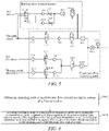
- FIG. 6 is a schematic flow diagram of a backup flow control method applicable to an anesthesia machine according to an embodiment of the disclosure. As shown in FIG. 6 , the method mainly includes the following steps.
- step S601 an operating state of the electronic flow control system is obtained by means of a first controller.
- the backup flow control system obtains the operating state of the electronic flow control system by means of the first control 1.
- the operating state of the electronic flow control system include a failure state and a working state.
- the failure state is at least one of: communication failure, valve failure, sensor failure, anesthesia machine power system failure and user interface failure of the electronic flow control system.
- the failure state may also include other failures that cause the electronic flow control system to fail to control a gas flow of the anesthesia machine, which are not limited in the embodiment of the disclosure.
- the working state is an state in which the electronic flow control system normally achieves the control of the gas flow of the anesthesia machine, and excludes the related failures included in the above-described failure states.
- the backup flow control system obtaining, when the first controller 1 is further included in the electronic flow control system, an operating state of the electronic flow control system by means of the first controller 1 includes: detecting the operating state of the electronic flow control system operating state by means of the first controller 1.
- the controllers of the electronic flow control system and the backup flow control system are different, namely, the electronic flow control system includes no first controller 1, an interaction between the electronic flow control system and the backup flow control system may be possible, such that the operating state of the electronic flow control system is obtained by mean of the first controller 1.
- the electronic flow control system includes the second controller 12, and the first controller 1 is connected to the second controller 12.
- the backup flow control system obtaining an operating state of the electronic flow control system by means of the first controller 1 includes: detecting the operating state of the electronic flow control system by means of the second controller 12; and receiving the operating state detected by the second controller 12 by means of the first controller 1.
- the first controller 1 obtaining an operating state of the electronic flow control system further includes: determining, by means of the first controller 1, that the operating state of the electronic flow control system is a failure state when the interruption of communication with the second controller 12 is detected.
- the second controller 12 itself fails, normal control of the gas flow by the electronic flow control system cannot be achieved, the communication between the first controller 1 and the second controller 12 will also be interrupted, and in this case, the first controller 1 may directly determine that the operating state of the electronic flow control system is the failure state.
- the backup ventilation mode is controlled to be turned on and the cover closing the accommodation cavity is opened such that the opening of the accommodation cavity opens to expose the flow regulation valve inside the accommodation cavity, or the backup ventilation mode is controlled to be turned off by means of the first controller according to the operating state of the electronic flow control system.
- the backup flow control system may control the backup ventilation mode to be turned on or off by means of the first controller 1 according to the operating state of the electronic flow control system.
- controlling the backup ventilation mode to be turned on and opening the cover 4 closing the accommodation cavity 3 or controlling the backup ventilation mode to be turned off and closing the cover 4 by means of the first controller 1 according to the operating state of the electronic flow control system includes: controlling, by means of the first controller 1, energization and de-energization of the electromagnet 5 according to the operating state of the electronic flow control system, where one of the permanent magnet 6 and the electromagnet 5 is fixed to the cover 4, the other one thereof is fixed to the accommodation cavity 3, the permanent magnet 6 corresponds to the electromagnet 5 in position, and the first controller 1 is connected to the electromagnet 5.
- the operating state of the electronic flow control system include a failure state and a working state
- controlling, by means of the first controller 1, energization and de-energization of the electromagnet 5 according to the operating state of the electronic flow control system includes: by means of the first controller 1, controlling the electromagnet 5 to be energized when the electronic flow control system is in the failure state, such that the magnetism generated by a magnetic pole at an end of the electromagnet 5 close to the permanent magnet 6 is the same as the magnetism generated by a magnetic pole at an end of the permanent magnet 6 close to the electromagnet 5 in order to separate the electromagnet 5 from the permanent magnet 6, and controlling the electromagnet 5 to be de-energized when the electronic flow control system is in the working state.
- the backup ventilation mode may also be turned on by means of an manual operation by the user.
- the backup flow control system may control, by means of the first controller 1, the backup ventilation mode to be turned on when the position sensor 7 detects that the cover is in an opened position; or may control, by means of the first controller 1, the backup ventilation mode to be turned on when it is detected that the electromagnet 5 generates a separating induction current, and control the backup ventilation mode to be turned off when it is detected that the electromagnet 5 generates an attracting induction current.
- the user may manually use the backup flow control system, namely, manually operate the backup flow control system to open the cover 4 closing the accommodation cavity 3 and turn on the backup ventilation mode.
- the first controller 1 may achieve detection of a position of the cover 4 by means of the position sensor 7 fixed to the cover 4 or to the accommodation cavity 3, thereby controlling the backup ventilation mode to be turned on when it is detected that the cover 4 is in the opened position. Furthermore, when the cover 4 is opened or closed, the electromagnet 5 generates a corresponding induction current, and the first controller 1 may determine that the cover 4 is in the opened position or the closed position by detecting the induction current, so as to turn on or off the backup ventilation mode.
- the backup flow control system may further include the system switch 8, the flow sensor 9, the glass tube flow meter 10, and the glass tube backlight 11.
- the user may manually switch off the system switch 8 for no leakage of the basic flow stored in the flow regulation valve 2 in the case of shutdown of the anesthesia machine.
- the flow sensor 9 may detect a flow through the flow regulation valve 2 and feed back the detected flow to the first controller 1.
- the glass tube flow meter 10 may display a gas flow regulated by the flow regulation valve 4 when the backup ventilation mode is turned on.
- the first controller 1 may control the glass tube backlight 11 to emit light when controlling the backup ventilation mode to be turned on, which gives a prompt that the backup ventilation mode is turned on.
- An embodiment of the disclosure provides a backup flow control method applicable to an anesthesia machine, the anesthesia machine including an electronic flow control system, the method including: obtaining an operating state of the electronic flow control system by means of a first controller; and controlling a backup ventilation mode to be turned on and opening a cover closing an accommodation cavity such that an opening of the accommodation cavity opens to expose a flow regulation valve inside the accommodation cavity, or controlling the backup ventilation mode to be turned off by means of the first controller according to the operating state of the electronic flow control system.
- An embodiment of the disclosure provide a backup flow control system applicable to an anesthesia machine.
- the backup flow control system turns on a backup ventilation mode when an electronic flow control system of the anesthesia machine has failed.
- the backup flow control system includes: a first controller, a flow regulation valve, an accommodation cavity and a cover, where the accommodation cavity is a hollow structure having an opening, the cover is connected to the opening of the accommodation cavity to close the opening, and the flow regulation valve is disposed inside the accommodation cavity; and the first controller, according to an operating state of the electronic flow control system, controls to turn on the backup ventilation mode and to open the cover, such that the opening opens to expose the flow regulation valve, or controls to turn off the backup ventilation mode.
- the backup flow control system provided by the embodiment of the disclosure not only protects the flow regulation valve from accidental regulation by the openable cover, but also has a simple structure, and is capable of automatically opening the cover when backup ventilation is required, thereby improving flexibility and reliability.
Landscapes
- Health & Medical Sciences (AREA)
- Heart & Thoracic Surgery (AREA)
- Life Sciences & Earth Sciences (AREA)
- Engineering & Computer Science (AREA)
- Anesthesiology (AREA)
- Biomedical Technology (AREA)
- Emergency Medicine (AREA)
- Hematology (AREA)
- Pulmonology (AREA)
- Animal Behavior & Ethology (AREA)
- General Health & Medical Sciences (AREA)
- Public Health (AREA)
- Veterinary Medicine (AREA)
- Flow Control (AREA)
- Ventilation (AREA)
Abstract
Description
- Embodiments of the disclosure relate to the technical field of medical devices, and more particularly, to a backup flow control system and method applicable to an anesthesia machine.
- Two ways to control a fresh gas flow of an anesthesia machine are provided, one is to use a mechanical needle valve to regulate the flow, and the other is to use an electronic flow control system to control the flow, namely, the system automatically controls a flow of a gas circuit valve so as to reach an artificially set target flow or oxygen concentration. The electronic flow control system, due to its high accuracy of flow control, is widely applied in various types of anesthesia machines.
- In case of power failure and electronic device failure in the above-mentioned electronic flow control system, the anesthesia machine may not provide oxygen for a patient. Therefore, in general, it is possible to configure a backup flow control system for the electronic flow control system of the anesthesia machine, so as to achieve emergency ventilation in case of the failure of the electronic flow control system and to improve safety.
- At present, mainly three types of backup flow control systems are provided. In a first type of backup flow control system, a needle valve for emergency regulation is directly exposed outside the anesthesia machine, which is prone to accidental regulation and influencing a patient's ventilation. In a second type of backup flow control system, a needle valve is hidden under a cover, and when emergency ventilation is required, the cover is opened for switching to emergency ventilation, and a flow is then regulated by using the needle valve; however, it may be difficult for medical care personnel to find the cover in an emergency state, resulting in a delay in treatment. In a third type of backup flow control system, a needle valve is retracted inside an anesthesia machine, and when the electronic flow control system fails or is manually operated, the needle valve pops up for regulation, electronic control and manual control of popup and retraction of the needle valve need to be compatible, which resulting in a complicated structure. Therefore, the existing three types of backup flow control systems have low flexibility and reliability.
- In order to solve the above-mentioned technical problems, embodiments of the disclosure are expected to provide a backup flow control system and method applicable to an anesthesia machine, which not only protects a flow regulation valve from accidental regulation by means of an openable cover, but also is simple in structure, and is capable of automatically opening the cover when backup ventilation is required, thereby improving flexibility and reliability.
- The technical solutions of the embodiments of the disclosure may be implemented as follows.
- An embodiment of the disclosure provide a backup flow control system applicable to an anesthesia machine. The backup flow control system turns on a backup ventilation mode when an electronic flow control system of the anesthesia machine has failed, and the backup flow control system includes: a first controller, a flow regulation valve, an accommodation cavity and a cover,
- where the accommodation cavity is a hollow structure having an opening, the cover is connected to the opening of the accommodation cavity to close the opening, and the flow regulation valve is disposed inside the accommodation cavity; and
- the first controller, according to an operating state of the electronic flow control system, controls to turns on the backup ventilation mode and to open the cover, such that the opening opens to expose the flow regulation valve; or controls to turn off the backup ventilation mode.
- The above-mentioned system further includes an electromagnet and a permanent magnet, where power sources for the electromagnet and the electronic flow control system are different, one of the permanent magnet and the electromagnet is fixed to the cover and the other one thereof is fixed to the accommodation cavity, and the permanent magnet corresponds to the electromagnet in position; and the first controller is connected to the electromagnet and controls to energize and de-energize of the electromagnet.
- In the above-mentioned system, the operating state of the electronic flow control system include a failure state and a working state.
- The first controller controls to energize the electromagnet when the electronic flow control system is in the failure state, such that the magnetism generated by a magnetic pole at an end of the electromagnet close to the permanent magnet is the same as the magnetism at an end of the permanent magnet close to the electromagnet in order to separate the electromagnet from the permanent magnet, and controls to de-energize the electromagnet when the electronic flow system is in the working state.
- In the above-mentioned system, the failure state is at least one of: communication failure, valve failure, sensor failure, anesthesia machine power system failure and user interface failure of the electronic flow control system.
- The above-mentioned system further includes a position sensor,
- where the position sensor is connected to the first controller and fixed to the cover or the accommodation cavity; and
- the first controller controls to turn on the backup ventilation mode when the position sensor detects that the cover is opened.
- In the above-mentioned system, the position sensor is at least one of: a hall sensor, a photoelectric coupling sensor and a position switch.
- In the above-mentioned system, the first controller controls to turn on the backup ventilation mode when it is detected that the electromagnet generates a separating induction current, and controls to turn off the backup ventilation mode when it is detected that the electromagnet generates an attracting induction current.
- In the above-mentioned system, the flow regulation valve regulates a flow of a gas delivered to a patient according to a received regulation operation, when the backup ventilation mode is turned on, and stores a basic flow therein, when the backup ventilation mode is turned off.
- In the above-mentioned system, the gas is oxygen, or oxygen and air.
- The above-mentioned system further includes a system switch,
- where the system switch is connected to the flow regulation valve; and
- the system switch prevents leakage of the basic flow stored in the flow regulation valve, when in the closed state.
- The above-mentioned system further includes a flow sensor,
where the flow sensor is connected to the flow regulation valve and the first controller, so as to detect a flow through the flow regulation valve and to feedback the detected flow to the first controller. - The above-mentioned system further includes a glass tube flow meter,
where the glass tube flow meter is connected to the flow regulation valve, so as to display a gas flow regulated by the flow regulation valve, when the backup ventilation mode is turn. - The above-mentioned system further includes a glass tube backlight,
- where the glass tube backlight is disposed at a back of the glass tube flow meter and is connected to the first controller, and
- the first controller controls the glass tube backlight to emit light when controlling to turn on the backup ventilation mode.
- In the above-mentioned system, power sources for the electromagnet and the glass tube backlight are different from a power source for the electronic flow control system.
- In the above-mentioned system, the first controller is also included in the electronic flow control system,
and the first controller detects an operating state of the electronic flow control system. - In the above-mentioned system, the electromagnet is energized and separated from the permanent magnet, when the first controller fails, thereby controlling to open the cover.
- In the above-mentioned system, the electronic flow control system includes a second controller,
- where the first controller is connected to the second controller; and
- the second controller detects an operating state of the electronic flow control system and transmits the detected operating state to the first controller.
- In the above-mentioned system, the first controller determines that the operating state of the electronic flow control system is a failure state when the interruption of communication with the second controller is detected.
- An embodiment of the disclosure provides a backup flow control method applicable to an anesthesia machine, the anesthesia machine including an electronic flow control system, the method including:
- obtaining an operating state of the electronic flow control system by means of a first controller; and
- controlling, by the first controller, to turn on a backup ventilation mode and to open a cover that closes an accommodation cavity, such that an opening of the accommodation cavity opens to expose a flow regulation valve inside the accommodation cavity, or controlling, by the first controller, to turn off the backup ventilation mode according to the operating state of the electronic flow control system.
- In the above-mentioned method, controlling, by the first controller, to turn on a backup ventilation mode and to open a cover that closes an accommodation cavity, or controlling, by the first controller, to turn off the backup ventilation mode according to the operating state of the electronic flow control system includes:
- controlling, by the first controller, to energize and de-energize an electromagnet according to the operating state of the electronic flow control system;
- where one of a permanent magnet and the electromagnet is fixed to the cover, the other one thereof is fixed to the accommodation cavity, the permanent magnet corresponds to the electromagnet in position, and the first controller is connected to the electromagnet.
- In the above-mentioned method, the operating state of the electronic flow control system include a failure state and a working state, and controlling, by the first controller, to energize and de-energize an electromagnet according to the operating state of the electronic flow control system includes:
controlling, by the first controller, to energize the electromagnet when the electronic flow control system is in the failure state, such that the magnetism generated by a magnetic pole at an end of the electromagnet close to the permanent magnet is the same as the magnetism generated by a magnetic pole at an end of the permanent magnet close to the electromagnet in order to separate the electromagnet from the permanent magnet, and controlling, by the first controller, to de-energize the electromagnet when the electronic flow control system is in the working state. - The above-mentioned method further includes:
controlling, by the first controller, to turn on the backup ventilation mode when a position sensor detects that the cover is opened. - The above-mentioned method further includes:
controlling, by the first controller, to turn on the backup ventilation mode when it is detected that the electromagnet generates a separating induction current, and controlling, by the first controller, to turn off the backup ventilation mode when it is detected that the electromagnet generates an attracting induction current. - In the above-mentioned method, if the first controller is also included in the electronic flow control system, obtaining an operating state of the electronic flow control system by the first controller includes:
detecting the operating state of the electronic flow control system by the first controller. - In the above-mentioned method, the electronic flow control system includes a second controller, the first controller being connected to the second controller, and obtaining an operating state of the electronic flow control system by the first controller includes:
- detecting the operating state of the electronic flow control system by the second controller; and
- receiving, by the first controller, the operating state detected by the second controller.
- In the above-mentioned method, obtaining an operating state of the electronic flow control system by the first controller further includes:
determining, by the first controller, that the operating state of the electronic flow control system is a failure state when interruption of communication with the second controller is detected. - An embodiment of the disclosure provide a backup flow control system applicable to an anesthesia machine. The backup flow control system turns on a backup ventilation mode when an electronic flow control system of the anesthesia machine has failed. The backup flow control system includes: a first controller, a flow regulation valve, an accommodation cavity and a cover, where the accommodation cavity is a hollow structure having an opening, the cover is connected to the opening of the accommodation cavity to close the opening, and the flow regulation valve is disposed inside the accommodation cavity; and the first controller, according to an operating state of the electronic flow control system, controls to turn on the backup ventilation mode and to open the cover, such that the opening opens to expose the flow regulation valve, or controls to turn off the backup ventilation mode. The backup flow control system provided by the embodiment of the disclosure not only protects the flow regulation valve from accidental regulation by the openable cover, but also has a simple structure, and is capable of automatically opening the cover when backup ventilation is required, thereby improving flexibility and reliability.
-
-
FIG. 1 is a first schematic structural diagram of a backup flow control system applicable to an anesthesia machine according to an embodiment of the disclosure; -
FIG. 2 is a second schematic structural diagram of a backup flow control system applicable to an anesthesia machine according to an embodiment of the disclosure; -
FIG. 3 is a third schematic structural diagram of a backup flow control system applicable to an anesthesia machine according to an embodiment of the disclosure; -
FIG. 4 is a first schematic diagram of a connection between an exemplary backup flow control system and an electronic flow control system according to an embodiment of the disclosure; -
FIG. 5 is a second schematic diagram of a connection between an exemplary backup flow control system and an electronic flow control system according to an embodiment of the disclosure; and -
FIG. 6 is a schematic flow diagram of a backup flow control method applicable to an anesthesia machine according to an embodiment of the disclosure. - The description has been made with reference to various example embodiments herein. However, persons skilled in the art should appreciate that changes and modifications may be made to the example embodiments without departing from the scope herein. For example, various operation steps and assemblies for executing operation steps may be implemented in different ways according to a specific application or considering any number of cost functions associated with the operation of the system (for example, one or more steps may be deleted, modified, or incorporated into other steps).
- The terms "first", "second" and the like in the specification and the claims of the disclosure and the above drawings are used to distinguish different objects, but not to describe a specific order. In addition, the terms "include", "have", and any variations thereof are intended to cover non-exclusive inclusion. For example, a process, a method, a system, a product, or a device that includes a series of steps or units is not limited to the listed steps or units, but optionally further includes unlisted steps or units, or optionally further includes other steps or units inherent in these processes, methods, or devices.
- In order to understand the features and technical contents of embodiments of the disclosure in more detail, the implementation of the embodiments of the disclosure will be described below in detail with reference to the accompanying drawings, which are for reference and illustration only, and are not intended to limit the embodiments of the disclosure.
- The embodiments of the disclosure provide a backup flow control system applicable to an anesthesia machine. The backup flow control system enters a backup ventilation mode when an electronic flow control system of the anesthesia machine has failed.
FIG. 1 is a first schematic structural diagram of a backup flow control system applicable to an anesthesia machine according to an embodiment of the disclosure. As shown inFIG. 1 , the backup flow control system includes: afirst controller 1, aflow regulation valve 2, anaccommodation cavity 3 and acover 4. - Specifically, in this embodiment of the disclosure, the
accommodation cavity 3 is a hollow structure having an opening, thecover 4 is connected to the opening of theaccommodation cavity 3 to close the opening, and the flow regulation valve is disposed inside the accommodation cavity. - The
first controller 1, according to an operating state of the electronic flow control system, controls to turn on a backup ventilation mode and to open thecover 4, such that the opening opens to expose theflow regulation valve 2; or controls to turn off the backup ventilation mode. - It should be noted that one or more
first controllers 1 and one or moreflow regulation valves 2 may be provided in this embodiment of the disclosure. The specific number of thefirst controllers 1 and the specific number of theflow regulation valves 2 may be set according to actual requirements, and are not limited in the embodiment of the disclosure. - It should be noted that in the embodiment of the disclosure, the
flow regulation mode 2 may be specifically a mechanical needle valve configured to regulate a flow. Of course, theflow regulation valve 2 may also be other types of devices configured to achieve flow regulation, which are not limited in the embodiment of the disclosure. - It should be noted that one or more
first controllers 1 may be provided in the embodiment of the disclosure. In a case where a plurality offirst controllers 1 are provided, the plurality offirst controllers 1 may monitor their operating states mutually, such that normalfirst controllers 1 may be used to turn on or off the backup ventilation mode in the event of failure of some of thefirst controllers 1. The specific number of thefirst controllers 1 may be set according to actual requirements, and is not limited in the embodiment of the disclosure. - It will be appreciated that in the embodiment of the disclosure, the
first controller 1 may control opening and closing of thecover 4 according to the operating state of the electronic flow control system such that the cover may be automatically opened to facilitate an operation by a user when backup ventilation is required. The way in which thefirst controller 1 achieves control of the opening and closing of the cover is not limited in the embodiment of the disclosure. -
FIG. 2 is a second schematic structural diagram of a backup flow control system applicable to an anesthesia machine according to an embodiment of the disclosure. As shown inFIG. 2 , in this embodiment of the disclosure, the backup flow ventilation system further includes anelectromagnet 5 and apermanent magnet 6, where power sources for theelectromagnet 5 and the electronic flow control system are different, one of thepermanent magnet 6 and theelectromagnet 5 is fixed to thecover 4, and the other one thereof is fixed to theaccommodation cavity 3, and thepermanent magnet 6 corresponds to theelectromagnet 5 in position. Thefirst controller 1 is connected to theelectromagnet 5 to control to energize and de-energized of theelectromagnet 5. - It should be noted that one or
more electromagnets 5 and one or morepermanent magnets 6 may be provided in the embodiment of the disclosure. The specific number of theelectromagnets 5 and the specific number of thepermanent magnets 6 may be set according to actual requirements, and are not limited in the embodiment of the disclosure. - It should be noted that in the embodiment of the disclosure, as shown in
FIG. 1 , it is preferable to fix thepermanent magnet 6 to thecover 4 and fix theelectromagnet 5 to theaccommodation cavity 3, and the permanent magnet corresponds to the electromagnet in position, so as to facilitate the routing of theelectromagnet 5. - It will be appreciated that in the embodiment of the disclosure, one of the
electromagnet 5 and thepermanent magnet 6 is fixed to thecover 4, the other is fixed to theaccommodation cavity 3, and the electromagnet corresponds to the permanent magnet in position. Therefore, when thefirst controller 1 controls theelectromagnet 5 to be separated from thepermanent magnet 6, theaccommodation cavity 3 may be separated from thecover 4 accordingly, such that the opening of theaccommodation cavity 3 opens, and the user may operate theflow regulation valve 2 to control a flow. When theelectromagnet 5 and thepermanent magnet 6 are attracted to each other, it is possible to engage theaccommodation cavity 3 with thecover 4 accordingly, such that the opening of theaccommodation cavity 3 is closed, and theflow regulation valve 2 is enclosed inside theaccommodation cavity 3. - It should be noted that in the embodiment of the disclosure, the
cover 4 may be made of a transparent or translucent material, such that the user may know that theflow regulation valve 2 is disposed inside theaccommodation cavity 3. - Specifically, in the embodiment of the disclosure, the operating state of the electronic flow control system of the anesthesia machine includes a failure state in which the
first controller 1 controls to energize theelectromagnet 5, such that the magnetism generated by a magnetic pole at an end of theelectromagnet 5 close to thepermanent magnet 6 is the same as the magnet generated by a magnetic pole at an end of thepermanent magnet 6 close to theelectromagnet 5 in order to separate theelectromagnet 5 from thepermanent magnet 6, and a working state in which the first controller controls to be de-energize theelectromagnet 5. - It will be appreciated that in the embodiment of the disclosure, after the
first controller 1 controls to de-energize theelectromagnet 5, the user may manually operate to push thecover 4 toward the opening of theaccommodation cavity 3, such that thepermanent magnet 6 may magnetize theelectromagnet 5 when the cove approaches at a certain distance from the accommodation cavity, allowing theelectromagnet 5 and thepermanent magnet 6 to attract each other so as to close the opening of theaccommodation cavity 3. - Specifically, in the embodiment of the disclosure, the failure state of the electronic flow control system is at least one of: communication failure, valve failure, sensor failure, anesthesia machine power system failure and user interface failure of the electronic flow control system.
- It should be noted that in the embodiment of the disclosure, the above-described failure states are a few exemplary failure states listed. Of course, in a practical application, the failure state may also include other failures that cause the electronic flow control system to fail to control a gas flow of the anesthesia machine, which are not limited in the embodiment of the disclosure.
- It will be appreciated that in the embodiment of the disclosure, the working state of the electronic flow control system, namely, a state in which the electronic flow control system normally controls a gas flow of an anesthesia machine, excludes the related failures included in the above-described failure states.
- It will be appreciated that in the case of the anesthesia machine using the electronic flow control system to control the gas flow, if the electronic flow control system is in a failure state, a relevant gas such as oxygen and air cannot be normally supplied to a patient, resulting in medical risks. Thus, in the embodiment of the disclosure, the backup flow control system may, when the electronic flow control system fails, control to turn on the backup ventilation mode in time for operating the
flow regulation valve 2 by a user, ensuring the safety of the patient. -
FIG. 3 is a third schematic structural diagram of an electronic flow control system according to an embodiment of the disclosure. As shown inFIGS. 2 and3 , the backup flow control system may further include aposition sensor 7, where theposition sensor 7 is connected to thefirst controller 1 and is fixed to thecover 4 or theaccommodation cavity 3. Thefirst controller 1 controls to turn on the backup ventilation mode when theposition sensor 7 detects that thecover 4 is open. - It should be noted that in the embodiment of the disclosure, as shown in
FIGS. 2 and3 , theposition sensor 7 is fixed to thecover 4, of course, may be actually fixed to theaccommodation cavity 3, which is not limited in the embodiment of the disclosure. - In particular, in the embodiment of the disclosure, the
position sensor 7 is at least one of: a hall sensor, a photoelectric coupling sensor and a position switch. Of course, theposition sensor 7 may also be other devices configured to achieve position detection, and may be selected according to actual requirements, which is not limited in the embodiment of the disclosure. - It should be noted that one or
more position sensors 7 may be provided in the embodiment of the disclosure. With a plurality ofposition sensors 7, a problem that asingle position sensor 7 fails and therefore the position of thecover 4 cannot be detected may be prevented. The specific number of theposition sensors 7 may be selected according to actual requirements, and is not limited in the embodiment of the disclosure. - It will be appreciated that in the embodiment of the disclosure, the failure state such as the anesthesia machine power system failure or the user interface failure, for example, a failure such as a blank screen of a display screen, may be directly observed by the user, and therefore, the user may directly and manually open the
cover 4 closing theaccommodation cavity 3, theposition sensor 7 thus detects that thecover 4 is in the opened position, and the user controls to turn on the backup ventilation mode and then can repair or replace relevant devices. - Specifically, in the embodiment of the disclosure, the
first controller 1 is further configured to control to turn on the backup ventilation mode when detecting that theelectromagnet 5 generates a separating induction current, and to control to turn off the backup ventilation mode when detecting that theelectromagnet 5 generates an attracting induction current. - It will be appreciated that in the embodiment of the disclosure, the backup flow control system may also include no
position sensor 7 for detecting the position of thecover 4. When thecover 4 is opened or closed, theelectromagnet 5 will generate a corresponding induction current, such that whether thecover 4 is open or close may be determined, and the on or off of the backup ventilation mode may be controlled. - Specifically, in the embodiment of the disclosure, the
flow regulation valve 2, when the backup ventilation mode is turned on, regulates a flow of a gas delivered to the patient according to a received regulation operation, and when the backup ventilation mode is turned off, stores a basic flow therein. - It should be noted that in the embodiment of the disclosure, the gas controlled by the
flow regulation valve 2 is oxygen or oxygen and air. Specifically, when only oneflow regulation valve 2 is disposed inside theaccommodation cavity 6, control of oxygen is preferably applied to avoid hypoxia of the patient, and when a plurality offlow regulation valves 2 are disposed inside theaccommodation cavity 3, respective control of flows of a plurality of types of gases may be achieved. - It will be appreciated that in the embodiment of the disclosure, the
flow regulation valve 2 may store the basic flow when the backup ventilation mode is turned off, such that when the backup ventilation mode is controlled to be turned on next time, the basic flow may be supplied to the patient, avoiding the hypoxia of the patient due to the fact that the user does not operate theflow regulation valve 2 in time. - Specifically, in the embodiment of the disclosure, as shown in
FIG. 2 , the backup flow control system may further include asystem switch 8, where thesystem switch 8 is connected to theflow regulation valve 2. Thesystem switch 8, when in an OFF state, prevents leakage of the basic flow stored in theflow regulation valve 2. - It will be appreciated that in the embodiment of the disclosure, the
flow regulation valve 2 is connected to the manually controlledsystem switch 8 such that thesystem switch 8 is manually switched off in the case of shutdown of the anesthesia machine, actually in the case where the electronic flow control system is in a failure state, to avoid leakage of the basic flow stored in theflow regulation valve 2. Of course, in the case of turning on the anesthesia machine, it is also necessary to manually switch on thesystem switch 8 such that the gas may be delivered to the patient when the backup ventilation mode is turned on. - Specifically, in the embodiment of the disclosure, as shown in
FIG. 2 , the backup flow control system may further include a flow sensor 9, where the flow sensor 9 is connected to theflow regulation valve 2 and thefirst controller 1 to detect the flow through theflow regulation valve 2 and to feedback the detected flow to thefirst controller 1. - It may be understood that in the embodiment of the disclosure, the flow sensor 9 may feedback the detected flow through the
flow regulation valve 2 to thefirst controller 1, and when the backup ventilation mode is turned off and the electronic flow control system is activated for flow control, thefirst controller 1 may prompt the user to turn off theflow regulation valve 2 first, according to a detection result of the flow, avoiding a surge in flow when the backup ventilation mode is turned on next time. - It should be noted that in the embodiment of the disclosure, the
flow regulation valve 2 may further be actually connected to a regulation valve switch, and whether theflow regulation valve 2 is turned off or not is detected by means of the regulation valve switch. - Specifically, in an embodiment of the disclosure, as shown in
FIGS. 2 and3 , the backup flow control system may further include a glasstube flow meter 10, where the glasstube flow meter 10 is connected to theflow regulation valve 2 to display, when the backup ventilation mode is turned on, the gas flow regulated by theflow regulation valve 2. - It will be appreciated that in the embodiment of the disclosure, the glass
tube flow meter 4 may display the gas flow regulated by theflow regulation valve 2 when the backup ventilation mode is turned on, such that the user can visually know whether an operation on theflow regulation valve 2 achieves expected flow control and make a corresponding adjustment. - Specifically, in the embodiment of the disclosure, as shown in
FIGS. 2 and3 , the backup flow control system further includes aglass tube backlight 11, where theglass tube backlight 11 is installed on the back of the glasstube flow meter 10 and connected to thefirst controller 1. Thefirst controller 1 controls theglass tube backlight 11 to emit light when controlling to turn on the backup ventilation mode. - It will be appreciated that in the embodiment of the disclosure, when the backup ventilation mode is turned on, the
glass tube backlight 11 emits light, thereby achieving the effect of giving the user a prompt that the backup ventilation mode has been turned on. - It should be noted that in the embodiment of the disclosure, a power source for the
electromagnet 5 and theglass tube backlight 11 is different from the power source for the electronic flow control system. Thus, theelectromagnet 5 and theglass tube backlight 11 may operate normally even when a failure occurs to the power source of the electronic flow control system. - It should be noted that in embodiments of the disclosure, the operating state of the electronic flow control system may be identified by different devices.
- In particular, in an embodiment of the disclosure, the electronic flow control system may include the
first controller 1, namely, thefirst controller 1 is also a control device of the electronic flow control system, and the electronic flow control system shares one controller with the backup flow control system. Therefore, thefirst controller 1 may detect the operating state of the electronic flow control system. - It should be noted that in the embodiment of the disclosure, in a case where the electronic flow control system share the
first controller 1 with the backup flow control system, when thefirst controller 1 fails, theelectromagnet 5 is in an energized state by default and separated from thepermanent magnet 6, thereby controlling to open thecover 4. -
FIG. 4 is a first schematic diagram of a connection between an exemplary backup flow control system and an electronic flow control system according to an embodiment of the disclosure. As shown inFIG. 4 , in the embodiment of the disclosure, the electronic flow control system includes asecond controller 12, where thefirst controller 1 is connected to thesecond controller 12. Thesecond controller 12 detects an operating state of the electronic flow control system and transmits the detected operating state to thefirst controller 1. - It will be appreciated that in the embodiment of the disclosure, in a case where the electronic flow control system and the backup flow control system use different controllers, the
second controller 12 of the electronic flow control system may achieve detection of the operating state of the electronic flow control system, thereby transmitting the detected operating state to thefirst controller 1 of the backup electronic flow control system for thefirst controller 1 to achieve control of opening and closing of thecover 4. - It should be noted that in the embodiment of the disclosure, the
first controller 1 determines that the operating state of the electronic flow control system is a failure state when the interruption of communication with thesecond controller 12 is detected. - It will be appreciated that in the embodiment of the disclosure, if the
second controller 12 of the electronic flow control system itself fails, the communication between thefirst controller 1 and thesecond controller 12 will be interrupted, and thus thefirst controller 1 may determine that the operating state of the electronic flow control system is the failure state. -
FIG. 5 is a second schematic diagram of a connection between an exemplary backup flow control system and an electronic flow control system according to an embodiment of the disclosure. As shown inFIG. 5 , the backup flow control system may include: asystem switch 8, an one-way valve 11.1, an oxygen needle valve 11.2, an one-way valve 11.3, an air needle valve 11.4, a float flow meter 11.5, and a normally open switch valve 11.6. The oxygen needle valve 11.2 and the air needle valve 11.4 act as twoflow regulation valves 1, such that when the backup ventilation mode is turned on, flow control of oxygen and air is correspondingly achieved. The float flow meter 11.5 is the above-mentioned glasstube flow meter 10, and displays a gas flow when the backup ventilation mode is turned on. The normally open switch valve 11.6 is opened when the backup ventilation mode is turned on. The electronic flow control system includes: a filter 12.1, a normally closed switch valve 12.2, an one-way valve 12.3, a proportional valve 12.4, a flow sensor 12.5, a filter 12.6, a 2/3 switching valve 12.7, an one-way valve 12.8, a filter 12.9, a 2/3 switching valve 12.10, an one-way valve 12.11, a proportional valve 12.12, a flow sensor 12.13, a flow sensor 12.14 and a pressure sensor 12.15. The normally closed switch valve 12.2 is closed when the backup ventilation mode is turned on, such that oxygen enters the backup electronic flow control system to achieve flow control. In a case where the operating state of the electronic flow control system is a working state, a process during which the above-described devices included in the electronic flow control system cooperatively operate to achieve normal oxygen delivery to the patient is known in the prior art, and will not be described in detail herein. - An embodiment of the disclosure provide a backup flow control system applicable to an anesthesia machine. The backup flow control system turns on a backup ventilation mode when an electronic flow control system of the anesthesia machine has failed. The backup flow control system includes: a first controller, a flow regulation valve, an accommodation cavity and a cover, where the accommodation cavity is a hollow structure having an opening, the cover is connected to the opening of the accommodation cavity to close the opening, and the flow regulation valve is disposed inside the accommodation cavity; and the first controller, according to an operating state of the electronic flow control system, controls the backup ventilation mode to be turned on and the cover is opened such that the opening opens to expose the flow regulation valve, or controls the backup ventilation mode to be turned off. The backup flow control system provided by the embodiment of the disclosure not only protects the flow regulation valve from accidental regulation by means of the openable cover, but also has a simple structure, and is capable of automatically opening the cover when backup ventilation is required, thereby improving flexibility and reliability.
- An embodiment of the disclosure provides a backup flow control method applicable to an anesthesia machine, the anesthesia machine including an electronic flow control system.
FIG. 6 is a schematic flow diagram of a backup flow control method applicable to an anesthesia machine according to an embodiment of the disclosure. As shown inFIG. 6 , the method mainly includes the following steps. - At step S601, an operating state of the electronic flow control system is obtained by means of a first controller.
- In the embodiments of the disclosure, referring to
FIGS. 1 to 4 , the backup flow control system obtains the operating state of the electronic flow control system by means of thefirst control 1. - It should be noted that in the embodiments of the disclosure, the operating state of the electronic flow control system include a failure state and a working state. The failure state is at least one of: communication failure, valve failure, sensor failure, anesthesia machine power system failure and user interface failure of the electronic flow control system. Of course, in a practical application, the failure state may also include other failures that cause the electronic flow control system to fail to control a gas flow of the anesthesia machine, which are not limited in the embodiment of the disclosure. The working state is an state in which the electronic flow control system normally achieves the control of the gas flow of the anesthesia machine, and excludes the related failures included in the above-described failure states.
- It should be noted that in the embodiments of the disclosure, the backup flow control system obtaining, when the
first controller 1 is further included in the electronic flow control system, an operating state of the electronic flow control system by means of thefirst controller 1 includes: detecting the operating state of the electronic flow control system operating state by means of thefirst controller 1. - It should be noted that in the embodiments of the disclosure, in a case where the controllers of the electronic flow control system and the backup flow control system are different, namely, the electronic flow control system includes no
first controller 1, an interaction between the electronic flow control system and the backup flow control system may be possible, such that the operating state of the electronic flow control system is obtained by mean of thefirst controller 1. - Specifically, in the embodiments of the disclosure, the electronic flow control system includes the
second controller 12, and thefirst controller 1 is connected to thesecond controller 12. The backup flow control system obtaining an operating state of the electronic flow control system by means of thefirst controller 1 includes: detecting the operating state of the electronic flow control system by means of thesecond controller 12; and receiving the operating state detected by thesecond controller 12 by means of thefirst controller 1. - It should be noted that in the embodiments of the disclosure, in a case where the electronic flow control system includes the
second controller 12 and thefirst controller 1 obtains the operating state of the electronic flow control system by means of thesecond controller 12, thefirst controller 1 obtaining an operating state of the electronic flow control system further includes: determining, by means of thefirst controller 1, that the operating state of the electronic flow control system is a failure state when the interruption of communication with thesecond controller 12 is detected. - It will be appreciated that in the embodiments of the disclosure, if the
second controller 12 itself fails, normal control of the gas flow by the electronic flow control system cannot be achieved, the communication between thefirst controller 1 and thesecond controller 12 will also be interrupted, and in this case, thefirst controller 1 may directly determine that the operating state of the electronic flow control system is the failure state. - At step S602, the backup ventilation mode is controlled to be turned on and the cover closing the accommodation cavity is opened such that the opening of the accommodation cavity opens to expose the flow regulation valve inside the accommodation cavity, or the backup ventilation mode is controlled to be turned off by means of the first controller according to the operating state of the electronic flow control system.
- In the embodiments of the disclosure, referring to
FIGS. 1 to 4 , after obtaining the operating state of the electronic flow control system, the backup flow control system may control the backup ventilation mode to be turned on or off by means of thefirst controller 1 according to the operating state of the electronic flow control system. - Specifically, in the embodiments of the disclosure, controlling the backup ventilation mode to be turned on and opening the
cover 4 closing theaccommodation cavity 3 or controlling the backup ventilation mode to be turned off and closing thecover 4 by means of thefirst controller 1 according to the operating state of the electronic flow control system includes: controlling, by means of thefirst controller 1, energization and de-energization of theelectromagnet 5 according to the operating state of the electronic flow control system, where one of thepermanent magnet 6 and theelectromagnet 5 is fixed to thecover 4, the other one thereof is fixed to theaccommodation cavity 3, thepermanent magnet 6 corresponds to theelectromagnet 5 in position, and thefirst controller 1 is connected to theelectromagnet 5. - It should be noted that in the embodiments of the disclosure, the operating state of the electronic flow control system include a failure state and a working state, and controlling, by means of the
first controller 1, energization and de-energization of theelectromagnet 5 according to the operating state of the electronic flow control system includes: by means of thefirst controller 1, controlling theelectromagnet 5 to be energized when the electronic flow control system is in the failure state, such that the magnetism generated by a magnetic pole at an end of theelectromagnet 5 close to thepermanent magnet 6 is the same as the magnetism generated by a magnetic pole at an end of thepermanent magnet 6 close to theelectromagnet 5 in order to separate theelectromagnet 5 from thepermanent magnet 6, and controlling theelectromagnet 5 to be de-energized when the electronic flow control system is in the working state. - It should be noted that in embodiments of the disclosure, the backup ventilation mode may also be turned on by means of an manual operation by the user.
- Specifically, in the embodiment of the disclosure, the backup flow control system may control, by means of the
first controller 1, the backup ventilation mode to be turned on when theposition sensor 7 detects that the cover is in an opened position;
or may control, by means of thefirst controller 1, the backup ventilation mode to be turned on when it is detected that theelectromagnet 5 generates a separating induction current, and control the backup ventilation mode to be turned off when it is detected that theelectromagnet 5 generates an attracting induction current. - It will be appreciated that in the embodiments of the disclosure, during practical application, in some cases, such as a blank screen problem of the anesthesia machine, it is also required to use the backup flow control system so as to repair and replace relevant devices of the anesthesia machine, and such a problem may be directly observed by a user. Therefore, the user may manually use the backup flow control system, namely, manually operate the backup flow control system to open the
cover 4 closing theaccommodation cavity 3 and turn on the backup ventilation mode. - It will be appreciated that in the embodiment of the disclosure, for a case where the user manually opens the
cover 4 closing theaccommodation cavity 3, thefirst controller 1 may achieve detection of a position of thecover 4 by means of theposition sensor 7 fixed to thecover 4 or to theaccommodation cavity 3, thereby controlling the backup ventilation mode to be turned on when it is detected that thecover 4 is in the opened position. Furthermore, when thecover 4 is opened or closed, theelectromagnet 5 generates a corresponding induction current, and thefirst controller 1 may determine that thecover 4 is in the opened position or the closed position by detecting the induction current, so as to turn on or off the backup ventilation mode. - It should be noted that in the embodiments of the disclosure, the backup flow control system may further include the
system switch 8, the flow sensor 9, the glasstube flow meter 10, and theglass tube backlight 11. The user may manually switch off thesystem switch 8 for no leakage of the basic flow stored in theflow regulation valve 2 in the case of shutdown of the anesthesia machine. The flow sensor 9 may detect a flow through theflow regulation valve 2 and feed back the detected flow to thefirst controller 1. The glasstube flow meter 10 may display a gas flow regulated by theflow regulation valve 4 when the backup ventilation mode is turned on. Thefirst controller 1 may control theglass tube backlight 11 to emit light when controlling the backup ventilation mode to be turned on, which gives a prompt that the backup ventilation mode is turned on. - An embodiment of the disclosure provides a backup flow control method applicable to an anesthesia machine, the anesthesia machine including an electronic flow control system, the method including: obtaining an operating state of the electronic flow control system by means of a first controller; and controlling a backup ventilation mode to be turned on and opening a cover closing an accommodation cavity such that an opening of the accommodation cavity opens to expose a flow regulation valve inside the accommodation cavity, or controlling the backup ventilation mode to be turned off by means of the first controller according to the operating state of the electronic flow control system. By means of the backup flow control method provided by the embodiments of the disclosure, not only the flow regulation valve is protected from accidental regulation by means of the openable cover, but also a simple structure is achieved, and the cover may be automatically opened when backup ventilation is required, thereby improving flexibility and reliability.
- The above descriptions are merely specific embodiments of the disclosure, but the scope of protection of the disclosure is not limited thereto. Changes or substitutions that may be readily conceived by those skilled in the art within the technical scope disclosed in the disclosure shall fall within the scope of protection of the disclosure. Therefore, the scope of protection of the disclosure shall be subject to the scope of protection of the claims.
- An embodiment of the disclosure provide a backup flow control system applicable to an anesthesia machine. The backup flow control system turns on a backup ventilation mode when an electronic flow control system of the anesthesia machine has failed. The backup flow control system includes: a first controller, a flow regulation valve, an accommodation cavity and a cover, where the accommodation cavity is a hollow structure having an opening, the cover is connected to the opening of the accommodation cavity to close the opening, and the flow regulation valve is disposed inside the accommodation cavity; and the first controller, according to an operating state of the electronic flow control system, controls to turn on the backup ventilation mode and to open the cover, such that the opening opens to expose the flow regulation valve, or controls to turn off the backup ventilation mode. The backup flow control system provided by the embodiment of the disclosure not only protects the flow regulation valve from accidental regulation by the openable cover, but also has a simple structure, and is capable of automatically opening the cover when backup ventilation is required, thereby improving flexibility and reliability.
Claims (26)
- A backup flow control system applicable to an anesthesia machine, characterized in that the backup flow control system turns on a backup ventilation mode when an electronic flow control system of the anesthesia machine has failed, and the backup flow control system comprises: a first controller, a flow regulation valve, an accommodation cavity and a cover, whereinthe accommodation cavity is a hollow structure having an opening, the cover is connected to the opening of the accommodation cavity to close the opening, and the flow regulation valve is disposed inside the accommodation cavity; andthe first controller, according to an operating state of the electronic flow control system, controls to turn on the backup ventilation mode and to open the cover, such that the opening opens to expose the flow regulation valve; orcontrols to turn off the backup ventilation mode.
- The system of claim 1, characterized in that, the system further comprises an electromagnet and a permanent magnet, wherein power sources for the electromagnet and the electronic flow control system are different, one of the permanent magnet and the electromagnet is fixed to the cover and the other one thereof is fixed to the accommodation cavity, and the permanent magnet corresponds to the electromagnet in position; and the first controller is connected to the electromagnet and controls to energize and de-energize the electromagnet.
- The system of claim 2, characterized in that the operating state of the electronic flow control system includes a failure state and a working state, and
the first controller controls to energize the electromagnet when the electronic flow control system is in the failure state, such that magnetism generated by a magnetic pole at an end of the electromagnet close to the permanent magnet is the same as magnetism generated by a magnetic pole at an end of the permanent magnet close to the electromagnet in order to separate the electromagnet from the permanent magnet, and controls to de-energize the electromagnet when the electronic flow system is in the working state. - The system of claim 3, characterized in that the failure state is at least one of: communication failure, valve failure, sensor failure, anesthesia machine power system failure and user interface failure of the electronic flow control system.
- The system of claim 1, characterized in that, the system further comprises a position sensor,wherein the position sensor is connected to the first controller and fixed to the cover or the accommodation cavity; andthe first controller controls to turn on the backup ventilation mode when the position sensor detects that the cover is opened.
- The system of claim 5, characterized in that the position sensor is at least one of: a hall sensor, a photoelectric coupling sensor and a position switch.
- The system of claim 2, characterized in that
the first controller controls to turn on the backup ventilation mode when it is detected that the electromagnet generates a separating induction current, and controls to turn off the backup ventilation mode when it is detected that the electromagnet generates an attracting induction current. - The system of claim 1, characterized in that
the flow regulation valveregulates a flow of a gas delivered to a patient according to a received regulation operation, when the backup ventilation mode is turned on, and stores a basic flow therein, when the backup ventilation mode is turned off. - The system of claim 8, characterized in that the gas is oxygen, or oxygen and air.
- The system of claim 8, characterized in that the system further comprises a system switch, ;wherein the system switch is connected to the flow regulation valve, ; andthe system switchprevents leakage of the basic flow stored in the flow regulation valve, when the system switch is closed.
- The system of claim 1, characterized in that the system further comprises a flow sensor,
wherein the flow sensor is connected to the flow regulation valve and the first controller to detect a flow through the flow regulation valve and to feed back the detected flow to the first controller. - The system of claim 1, characterized in that the system further comprises a glass tube flow meter,
wherein the glass tube flow meter is connected to the flow regulation valve, so as to display a gas flow regulated by the flow regulation valve, when the backup ventilation mode is turned on. - The system of claim 12, characterized in that the system further comprise a glass tube backlight,
wherein the glass tube backlight is disposed at a back of the glass tube flow meter and is connected to the first controller, and the first controller controls the glass tube backlight to emit light when controlling to turn on the backup ventilation mode. - The system of claim 13, characterized in that
a power source for the glass tube backlight is different from a power source for the electronic flow control system. - The system of claim 1, characterized in that the first controller is also included in the electronic flow control system, and
the first controller detects an operating state of the electronic flow control system. - The system of claim 2, characterized in that,
when the first controller fails, the electromagnet is energized and separated from the permanent magnet, thereby controlling to open the cover. - The system of claim 1, characterized in that the electronic flow control system comprises a second controller,
wherein the first controller is connected to the second controller; and
the second controller detects an operating state of the electronic flow control system and transmits the detected operating state to the first controller. - The system of claim 17, characterized in that
the first controller determines that the operating state of the electronic flow control system is a failure state when the interruption of communication with the second controller is detected. - A backup flow control method applicable to an anesthesia machine, the anesthesia machine comprising an electronic flow control system, characterized in that, the method comprises:obtaining an operating state of the electronic flow control system by a first controller; andcontrolling, by the first controller, to turn on a backup ventilation mode and to open a cover that closes an accommodation cavity such that an opening of the accommodation cavity opens to expose a flow regulation valve inside the accommodation cavity, or controlling, by the first controller, to turn off the backup ventilation mode according to the operating state of the electronic flow control system.
- The method of claim 19, characterized in that, controlling, by the first controller, to turn on a backup ventilation mode and to open a cover that closes an accommodation cavity, or controlling, by the first controller, to turn off the backup ventilation mode according to the operating state of the electronic flow control system comprises:controlling, by the first controller, to energize and de-energize an electromagnet according to the operating state of the electronic flow control system;wherein one of a permanent magnet and the electromagnet is fixed to the cover, the other one thereof is fixed to the accommodation cavity, the permanent magnet corresponds to the electromagnet in position, and the first controller is connected to the electromagnet.
- The method of claim 20, characterized in that, the operating state of the electronic flow control system include a failure state and a working state, and controlling, by the first controller, to energize and de-energize an electromagnet according to the operating state of the electronic flow control system comprises:
controlling, by the first controller, to energize the electromagnet when the electronic flow control system is in the failure state, such that magnetism generated by a magnetic pole at an end of the electromagnet close to the permanent magnet is the same as magnetism generated by a magnetic pole at an end of the permanent magnet close to the electromagnet, in order to separate the electromagnet from the permanent magnet, and controlling, by the first controller, to de-energize the electromagnet when the electronic flow control system is in the working state. - The method of claim 19, characterized in that, the method further comprises:
controlling, by the first controller, to turn on the backup ventilation mode when a position sensor detects that the cover is opened. - The method of claim 20, characterized in that the method further comprising:
by means of the first controller, controlling, by the first controller, to turn on the backup ventilation mode when it is detected that the electromagnet generates a separating induction current, and controlling, by the first controller, to turn off the backup ventilation mode when it is detected that the electromagnet generates an attracting induction current. - The method of claim 19, characterized in that, if the first controller is also included in the electronic flow control system, obtaining an operating state of the electronic flow control system by the first controller comprises:
detecting the operating state of the electronic flow control system by the first controller. - The method of claim 19, characterized in that the electronic flow control system comprises a second controller, the first controller being connected to the second controller, and obtaining an operating state of the electronic flow control system by the first controller comprises:detecting the operating state of the electronic flow control system by the second controller; andreceiving, by the first controller, the operating state detected by the second controller.
- The method of claim 25, characterized in that, obtaining an operating state of the electronic flow control system by the first controller further comprises:
determining, by the first controller, that the operating state of the electronic flow control system is a failure state when interruption of communication with the second controller is detected.
Applications Claiming Priority (1)
| Application Number | Priority Date | Filing Date | Title |
|---|---|---|---|
| PCT/CN2019/130185 WO2021134352A1 (en) | 2019-12-30 | 2019-12-30 | Backup flow control system and method applicable to anesthesia machine |
Publications (3)
| Publication Number | Publication Date |
|---|---|
| EP4085956A1 true EP4085956A1 (en) | 2022-11-09 |
| EP4085956A4 EP4085956A4 (en) | 2023-01-11 |
| EP4085956B1 EP4085956B1 (en) | 2024-08-07 |
Family
ID=76686150
Family Applications (1)
| Application Number | Title | Priority Date | Filing Date |
|---|---|---|---|
| EP19958510.0A Active EP4085956B1 (en) | 2019-12-30 | 2019-12-30 | Backup flow control system and method applicable to anesthesia machine |
Country Status (3)
| Country | Link |
|---|---|
| EP (1) | EP4085956B1 (en) |
| CN (1) | CN114616011B (en) |
| WO (1) | WO2021134352A1 (en) |
Families Citing this family (1)
| Publication number | Priority date | Publication date | Assignee | Title |
|---|---|---|---|---|
| CN113855982B (en) * | 2021-09-30 | 2023-07-18 | 深圳市科曼医疗设备有限公司 | Anesthesia vaporization device |
Family Cites Families (13)
| Publication number | Priority date | Publication date | Assignee | Title |
|---|---|---|---|---|
| WO2009006932A1 (en) * | 2007-07-06 | 2009-01-15 | Maquet Critical Care Ab | Expiratory valve of an anesthetic breathing apparatus having safety backup |
| CN202305529U (en) * | 2011-10-31 | 2012-07-04 | 深圳迈瑞生物医疗电子股份有限公司 | Blood cell analyzer and door opener thereof |
| CN103809621B (en) * | 2012-11-13 | 2018-04-06 | 深圳迈瑞生物医疗电子股份有限公司 | Standby electric-controlled type flow control system is used as using mechanical control |
| CN103800984B (en) * | 2012-11-13 | 2017-04-19 | 深圳迈瑞生物医疗电子股份有限公司 | Valve module for controlling fluid flow |
| CN103800983B (en) * | 2012-11-13 | 2017-04-19 | 深圳迈瑞生物医疗电子股份有限公司 | Valve assembly for controlling fluid flow |
| CN103809620B (en) * | 2012-11-13 | 2017-10-10 | 深圳迈瑞生物医疗电子股份有限公司 | electronic flow control method and system |
| CN103809622B (en) * | 2012-11-13 | 2017-07-28 | 深圳迈瑞生物医疗电子股份有限公司 | Standby electric-controlled type flow control system and method are used as using mechanical control |
| US20140130906A1 (en) * | 2012-11-14 | 2014-05-15 | Mindray Ds Usa, Inc. | Systems and methods for electronically controlling the flow rates of fluids |
| US8997784B2 (en) * | 2012-11-14 | 2015-04-07 | Shenzhen Mindray Bio-Medical Electronics Co. Ltd. | Electronic fluid flow controls with integrated manual fluid flow controls |
| US8887746B2 (en) * | 2012-11-14 | 2014-11-18 | Mindray Ds Usa, Inc. | Electronic and manual backup flow control systems |
| WO2014178730A2 (en) * | 2013-04-30 | 2014-11-06 | Iac Ip Limited | Anaesthetic machine |
| CN106902433B (en) * | 2015-12-23 | 2019-11-15 | 北京谊安医疗系统股份有限公司 | A kind of electronic flow meter systems and its control method |
| CN109771767B (en) * | 2019-01-29 | 2020-06-26 | 深圳市科曼医疗设备有限公司 | Pneumatic standby flow meter control system of anesthesia machine |
-
2019
- 2019-12-30 CN CN201980101433.7A patent/CN114616011B/en active Active
- 2019-12-30 EP EP19958510.0A patent/EP4085956B1/en active Active
- 2019-12-30 WO PCT/CN2019/130185 patent/WO2021134352A1/en not_active Ceased
Also Published As
| Publication number | Publication date |
|---|---|
| CN114616011B (en) | 2024-09-24 |
| CN114616011A (en) | 2022-06-10 |
| EP4085956A4 (en) | 2023-01-11 |
| WO2021134352A1 (en) | 2021-07-08 |
| EP4085956B1 (en) | 2024-08-07 |
Similar Documents
| Publication | Publication Date | Title |
|---|---|---|
| KR102046589B1 (en) | Residual-Current Device with Automatic Test | |
| US12023437B2 (en) | Insufflation system and insufflation control method | |
| EP4085956B1 (en) | Backup flow control system and method applicable to anesthesia machine | |
| US9935495B2 (en) | Automatic transfer switch | |
| KR101622677B1 (en) | Auxiliary power unit for emergency light upon fire state or power failaure | |
| KR101642436B1 (en) | Emergency power auto supply and control apparatus having a fire alarm | |
| KR20170116896A (en) | Emergency exit guide apparatus and emergency exit guide system with the same | |
| EP2709136B1 (en) | A relay and a method for indicating a relay failure | |
| CN104349559B (en) | The remote detecting system of intelligent lighting fault and detection method thereof | |
| KR101320996B1 (en) | Sensor fault diagnosis system | |
| US12048816B2 (en) | Anesthesia machine exhaust emission control system and control method therefor | |
| US20240133855A1 (en) | Method and Apparatus for Automatically Maintaining a Desired Level of Oxygen in a Refuge | |
| JP2725155B2 (en) | Main gas supply cut-off device when an abnormality occurs in the gas backup supply device | |
| JP2015175767A (en) | Status display system, display device, control device, and status display method | |
| KR101797372B1 (en) | Medical Gas Auto Manifold System | |
| CN214208768U (en) | Intelligent gas terminal | |
| CN218298853U (en) | Automatic liquid feeding device of liquid | |
| JPH04203806A (en) | Gas shut-off valve device | |
| CN104780645A (en) | Assembly room intelligent lighting linkage method and system | |
| CN205708245U (en) | A kind of overvoltage protective system and install the tank car of this system | |
| FI131972B1 (en) | Ventilation control system and ventilation system | |
| US20210082262A1 (en) | Lighting Fixture Having an Environmental Detection System | |
| JP2004117171A (en) | Gas safety equipment | |
| CN121677779A (en) | Pipeline detector based on magnetic induction and automatic startup and state display method | |
| CN116557783A (en) | Gas intelligent safety delivery cabinet |
Legal Events
| Date | Code | Title | Description |
|---|---|---|---|
| STAA | Information on the status of an ep patent application or granted ep patent |
Free format text: STATUS: THE INTERNATIONAL PUBLICATION HAS BEEN MADE |
|
| PUAI | Public reference made under article 153(3) epc to a published international application that has entered the european phase |
Free format text: ORIGINAL CODE: 0009012 |
|
| STAA | Information on the status of an ep patent application or granted ep patent |
Free format text: STATUS: REQUEST FOR EXAMINATION WAS MADE |
|
| 17P | Request for examination filed |
Effective date: 20220727 |
|
| AK | Designated contracting states |
Kind code of ref document: A1 Designated state(s): AL AT BE BG CH CY CZ DE DK EE ES FI FR GB GR HR HU IE IS IT LI LT LU LV MC MK MT NL NO PL PT RO RS SE SI SK SM TR |
|
| A4 | Supplementary search report drawn up and despatched |
Effective date: 20221213 |
|
| RIC1 | Information provided on ipc code assigned before grant |
Ipc: A61M 16/20 20060101ALI20221207BHEP Ipc: A61M 16/10 20060101ALI20221207BHEP Ipc: A61M 16/00 20060101ALI20221207BHEP Ipc: A61M 16/01 20060101AFI20221207BHEP |
|
| DAV | Request for validation of the european patent (deleted) | ||
| DAX | Request for extension of the european patent (deleted) | ||
| GRAP | Despatch of communication of intention to grant a patent |
Free format text: ORIGINAL CODE: EPIDOSNIGR1 |
|
| STAA | Information on the status of an ep patent application or granted ep patent |
Free format text: STATUS: GRANT OF PATENT IS INTENDED |
|
| INTG | Intention to grant announced |
Effective date: 20240301 |
|
| RAP3 | Party data changed (applicant data changed or rights of an application transferred) |
Owner name: SHENZHEN MINDRAY BIO-MEDICAL ELECTRONICS CO., LTD. |
|
| GRAS | Grant fee paid |
Free format text: ORIGINAL CODE: EPIDOSNIGR3 |
|
| GRAA | (expected) grant |
Free format text: ORIGINAL CODE: 0009210 |
|
| STAA | Information on the status of an ep patent application or granted ep patent |
Free format text: STATUS: THE PATENT HAS BEEN GRANTED |
|
| AK | Designated contracting states |
Kind code of ref document: B1 Designated state(s): AL AT BE BG CH CY CZ DE DK EE ES FI FR GB GR HR HU IE IS IT LI LT LU LV MC MK MT NL NO PL PT RO RS SE SI SK SM TR |
|
| REG | Reference to a national code |
Ref country code: GB Ref legal event code: FG4D |
|
| REG | Reference to a national code |
Ref country code: CH Ref legal event code: EP |
|
| REG | Reference to a national code |
Ref country code: IE Ref legal event code: FG4D |
|
| REG | Reference to a national code |
Ref country code: DE Ref legal event code: R096 Ref document number: 602019056850 Country of ref document: DE |
|
| P01 | Opt-out of the competence of the unified patent court (upc) registered |
Free format text: CASE NUMBER: APP_47972/2024 Effective date: 20240824 |
|
| REG | Reference to a national code |
Ref country code: SE Ref legal event code: TRGR |
|
| REG | Reference to a national code |
Ref country code: LT Ref legal event code: MG9D |
|
| REG | Reference to a national code |
Ref country code: NL Ref legal event code: MP Effective date: 20240807 |
|
| PG25 | Lapsed in a contracting state [announced via postgrant information from national office to epo] |
Ref country code: NO Free format text: LAPSE BECAUSE OF FAILURE TO SUBMIT A TRANSLATION OF THE DESCRIPTION OR TO PAY THE FEE WITHIN THE PRESCRIBED TIME-LIMIT Effective date: 20241107 |
|
| REG | Reference to a national code |
Ref country code: AT Ref legal event code: MK05 Ref document number: 1710256 Country of ref document: AT Kind code of ref document: T Effective date: 20240807 |
|
| PG25 | Lapsed in a contracting state [announced via postgrant information from national office to epo] |
Ref country code: PT Free format text: LAPSE BECAUSE OF FAILURE TO SUBMIT A TRANSLATION OF THE DESCRIPTION OR TO PAY THE FEE WITHIN THE PRESCRIBED TIME-LIMIT Effective date: 20241209 Ref country code: NL Free format text: LAPSE BECAUSE OF FAILURE TO SUBMIT A TRANSLATION OF THE DESCRIPTION OR TO PAY THE FEE WITHIN THE PRESCRIBED TIME-LIMIT Effective date: 20240807 Ref country code: FI Free format text: LAPSE BECAUSE OF FAILURE TO SUBMIT A TRANSLATION OF THE DESCRIPTION OR TO PAY THE FEE WITHIN THE PRESCRIBED TIME-LIMIT Effective date: 20240807 Ref country code: GR Free format text: LAPSE BECAUSE OF FAILURE TO SUBMIT A TRANSLATION OF THE DESCRIPTION OR TO PAY THE FEE WITHIN THE PRESCRIBED TIME-LIMIT Effective date: 20241108 Ref country code: PL Free format text: LAPSE BECAUSE OF FAILURE TO SUBMIT A TRANSLATION OF THE DESCRIPTION OR TO PAY THE FEE WITHIN THE PRESCRIBED TIME-LIMIT Effective date: 20240807 |
|
| PG25 | Lapsed in a contracting state [announced via postgrant information from national office to epo] |
Ref country code: BG Free format text: LAPSE BECAUSE OF FAILURE TO SUBMIT A TRANSLATION OF THE DESCRIPTION OR TO PAY THE FEE WITHIN THE PRESCRIBED TIME-LIMIT Effective date: 20240807 |
|
| PG25 | Lapsed in a contracting state [announced via postgrant information from national office to epo] |
Ref country code: LV Free format text: LAPSE BECAUSE OF FAILURE TO SUBMIT A TRANSLATION OF THE DESCRIPTION OR TO PAY THE FEE WITHIN THE PRESCRIBED TIME-LIMIT Effective date: 20240807 |
|
| PG25 | Lapsed in a contracting state [announced via postgrant information from national office to epo] |
Ref country code: AT Free format text: LAPSE BECAUSE OF FAILURE TO SUBMIT A TRANSLATION OF THE DESCRIPTION OR TO PAY THE FEE WITHIN THE PRESCRIBED TIME-LIMIT Effective date: 20240807 Ref country code: IS Free format text: LAPSE BECAUSE OF FAILURE TO SUBMIT A TRANSLATION OF THE DESCRIPTION OR TO PAY THE FEE WITHIN THE PRESCRIBED TIME-LIMIT Effective date: 20241207 |
|
| PG25 | Lapsed in a contracting state [announced via postgrant information from national office to epo] |
Ref country code: HR Free format text: LAPSE BECAUSE OF FAILURE TO SUBMIT A TRANSLATION OF THE DESCRIPTION OR TO PAY THE FEE WITHIN THE PRESCRIBED TIME-LIMIT Effective date: 20240807 |
|
| PG25 | Lapsed in a contracting state [announced via postgrant information from national office to epo] |
Ref country code: ES Free format text: LAPSE BECAUSE OF FAILURE TO SUBMIT A TRANSLATION OF THE DESCRIPTION OR TO PAY THE FEE WITHIN THE PRESCRIBED TIME-LIMIT Effective date: 20240807 Ref country code: RS Free format text: LAPSE BECAUSE OF FAILURE TO SUBMIT A TRANSLATION OF THE DESCRIPTION OR TO PAY THE FEE WITHIN THE PRESCRIBED TIME-LIMIT Effective date: 20241107 |
|
| PG25 | Lapsed in a contracting state [announced via postgrant information from national office to epo] |
Ref country code: RS Free format text: LAPSE BECAUSE OF FAILURE TO SUBMIT A TRANSLATION OF THE DESCRIPTION OR TO PAY THE FEE WITHIN THE PRESCRIBED TIME-LIMIT Effective date: 20241107 Ref country code: PT Free format text: LAPSE BECAUSE OF FAILURE TO SUBMIT A TRANSLATION OF THE DESCRIPTION OR TO PAY THE FEE WITHIN THE PRESCRIBED TIME-LIMIT Effective date: 20241209 Ref country code: PL Free format text: LAPSE BECAUSE OF FAILURE TO SUBMIT A TRANSLATION OF THE DESCRIPTION OR TO PAY THE FEE WITHIN THE PRESCRIBED TIME-LIMIT Effective date: 20240807 Ref country code: NO Free format text: LAPSE BECAUSE OF FAILURE TO SUBMIT A TRANSLATION OF THE DESCRIPTION OR TO PAY THE FEE WITHIN THE PRESCRIBED TIME-LIMIT Effective date: 20241107 Ref country code: NL Free format text: LAPSE BECAUSE OF FAILURE TO SUBMIT A TRANSLATION OF THE DESCRIPTION OR TO PAY THE FEE WITHIN THE PRESCRIBED TIME-LIMIT Effective date: 20240807 Ref country code: LV Free format text: LAPSE BECAUSE OF FAILURE TO SUBMIT A TRANSLATION OF THE DESCRIPTION OR TO PAY THE FEE WITHIN THE PRESCRIBED TIME-LIMIT Effective date: 20240807 Ref country code: IS Free format text: LAPSE BECAUSE OF FAILURE TO SUBMIT A TRANSLATION OF THE DESCRIPTION OR TO PAY THE FEE WITHIN THE PRESCRIBED TIME-LIMIT Effective date: 20241207 Ref country code: HR Free format text: LAPSE BECAUSE OF FAILURE TO SUBMIT A TRANSLATION OF THE DESCRIPTION OR TO PAY THE FEE WITHIN THE PRESCRIBED TIME-LIMIT Effective date: 20240807 Ref country code: GR Free format text: LAPSE BECAUSE OF FAILURE TO SUBMIT A TRANSLATION OF THE DESCRIPTION OR TO PAY THE FEE WITHIN THE PRESCRIBED TIME-LIMIT Effective date: 20241108 Ref country code: FI Free format text: LAPSE BECAUSE OF FAILURE TO SUBMIT A TRANSLATION OF THE DESCRIPTION OR TO PAY THE FEE WITHIN THE PRESCRIBED TIME-LIMIT Effective date: 20240807 Ref country code: ES Free format text: LAPSE BECAUSE OF FAILURE TO SUBMIT A TRANSLATION OF THE DESCRIPTION OR TO PAY THE FEE WITHIN THE PRESCRIBED TIME-LIMIT Effective date: 20240807 Ref country code: BG Free format text: LAPSE BECAUSE OF FAILURE TO SUBMIT A TRANSLATION OF THE DESCRIPTION OR TO PAY THE FEE WITHIN THE PRESCRIBED TIME-LIMIT Effective date: 20240807 Ref country code: AT Free format text: LAPSE BECAUSE OF FAILURE TO SUBMIT A TRANSLATION OF THE DESCRIPTION OR TO PAY THE FEE WITHIN THE PRESCRIBED TIME-LIMIT Effective date: 20240807 |
|
| PG25 | Lapsed in a contracting state [announced via postgrant information from national office to epo] |
Ref country code: DK Free format text: LAPSE BECAUSE OF FAILURE TO SUBMIT A TRANSLATION OF THE DESCRIPTION OR TO PAY THE FEE WITHIN THE PRESCRIBED TIME-LIMIT Effective date: 20240807 Ref country code: SM Free format text: LAPSE BECAUSE OF FAILURE TO SUBMIT A TRANSLATION OF THE DESCRIPTION OR TO PAY THE FEE WITHIN THE PRESCRIBED TIME-LIMIT Effective date: 20240807 |
|
| PG25 | Lapsed in a contracting state [announced via postgrant information from national office to epo] |
Ref country code: EE Free format text: LAPSE BECAUSE OF FAILURE TO SUBMIT A TRANSLATION OF THE DESCRIPTION OR TO PAY THE FEE WITHIN THE PRESCRIBED TIME-LIMIT Effective date: 20240807 |
|
| PG25 | Lapsed in a contracting state [announced via postgrant information from national office to epo] |
Ref country code: CZ Free format text: LAPSE BECAUSE OF FAILURE TO SUBMIT A TRANSLATION OF THE DESCRIPTION OR TO PAY THE FEE WITHIN THE PRESCRIBED TIME-LIMIT Effective date: 20240807 |
|
| PG25 | Lapsed in a contracting state [announced via postgrant information from national office to epo] |
Ref country code: SK Free format text: LAPSE BECAUSE OF FAILURE TO SUBMIT A TRANSLATION OF THE DESCRIPTION OR TO PAY THE FEE WITHIN THE PRESCRIBED TIME-LIMIT Effective date: 20240807 |
|
| REG | Reference to a national code |
Ref country code: DE Ref legal event code: R097 Ref document number: 602019056850 Country of ref document: DE |
|
| PLBE | No opposition filed within time limit |
Free format text: ORIGINAL CODE: 0009261 |
|
| STAA | Information on the status of an ep patent application or granted ep patent |
Free format text: STATUS: NO OPPOSITION FILED WITHIN TIME LIMIT |
|
| PG25 | Lapsed in a contracting state [announced via postgrant information from national office to epo] |
Ref country code: MC Free format text: LAPSE BECAUSE OF FAILURE TO SUBMIT A TRANSLATION OF THE DESCRIPTION OR TO PAY THE FEE WITHIN THE PRESCRIBED TIME-LIMIT Effective date: 20240807 |
|
| 26N | No opposition filed |
Effective date: 20250508 |
|
| REG | Reference to a national code |
Ref country code: CH Ref legal event code: PL |
|
| PG25 | Lapsed in a contracting state [announced via postgrant information from national office to epo] |
Ref country code: LU Free format text: LAPSE BECAUSE OF NON-PAYMENT OF DUE FEES Effective date: 20241230 |
|
| GBPC | Gb: european patent ceased through non-payment of renewal fee |
Effective date: 20241230 |
|
| REG | Reference to a national code |
Ref country code: BE Ref legal event code: MM Effective date: 20241231 |
|
| PG25 | Lapsed in a contracting state [announced via postgrant information from national office to epo] |
Ref country code: GB Free format text: LAPSE BECAUSE OF NON-PAYMENT OF DUE FEES Effective date: 20241230 Ref country code: BE Free format text: LAPSE BECAUSE OF NON-PAYMENT OF DUE FEES Effective date: 20241231 |
|
| PG25 | Lapsed in a contracting state [announced via postgrant information from national office to epo] |
Ref country code: FR Free format text: LAPSE BECAUSE OF NON-PAYMENT OF DUE FEES Effective date: 20241231 |
|
| PG25 | Lapsed in a contracting state [announced via postgrant information from national office to epo] |
Ref country code: CH Free format text: LAPSE BECAUSE OF NON-PAYMENT OF DUE FEES Effective date: 20241231 |
|
| PG25 | Lapsed in a contracting state [announced via postgrant information from national office to epo] |
Ref country code: IE Free format text: LAPSE BECAUSE OF NON-PAYMENT OF DUE FEES Effective date: 20241230 |
|
| PG25 | Lapsed in a contracting state [announced via postgrant information from national office to epo] |
Ref country code: RO Free format text: LAPSE BECAUSE OF FAILURE TO SUBMIT A TRANSLATION OF THE DESCRIPTION OR TO PAY THE FEE WITHIN THE PRESCRIBED TIME-LIMIT Effective date: 20240807 |
|
| PGFP | Annual fee paid to national office [announced via postgrant information from national office to epo] |
Ref country code: DE Payment date: 20251211 Year of fee payment: 7 |
|
| PGFP | Annual fee paid to national office [announced via postgrant information from national office to epo] |
Ref country code: SE Payment date: 20251219 Year of fee payment: 7 |
|
| PG25 | Lapsed in a contracting state [announced via postgrant information from national office to epo] |
Ref country code: IT Free format text: LAPSE BECAUSE OF FAILURE TO SUBMIT A TRANSLATION OF THE DESCRIPTION OR TO PAY THE FEE WITHIN THE PRESCRIBED TIME-LIMIT Effective date: 20240807 |
|
| PG25 | Lapsed in a contracting state [announced via postgrant information from national office to epo] |
Ref country code: CY Free format text: LAPSE BECAUSE OF FAILURE TO SUBMIT A TRANSLATION OF THE DESCRIPTION OR TO PAY THE FEE WITHIN THE PRESCRIBED TIME-LIMIT Effective date: 20240807 |