EP4085775A1 - Heater and smoking device comprising heater - Google Patents
Heater and smoking device comprising heater Download PDFInfo
- Publication number
- EP4085775A1 EP4085775A1 EP20893774.8A EP20893774A EP4085775A1 EP 4085775 A1 EP4085775 A1 EP 4085775A1 EP 20893774 A EP20893774 A EP 20893774A EP 4085775 A1 EP4085775 A1 EP 4085775A1
- Authority
- EP
- European Patent Office
- Prior art keywords
- electrode
- conductive portion
- base
- conductive
- flexible substrate
- Prior art date
- Legal status (The legal status is an assumption and is not a legal conclusion. Google has not performed a legal analysis and makes no representation as to the accuracy of the status listed.)
- Pending
Links
Images




Classifications
-
- A—HUMAN NECESSITIES
- A24—TOBACCO; CIGARS; CIGARETTES; SIMULATED SMOKING DEVICES; SMOKERS' REQUISITES
- A24F—SMOKERS' REQUISITES; MATCH BOXES; SIMULATED SMOKING DEVICES
- A24F40/00—Electrically operated smoking devices; Component parts thereof; Manufacture thereof; Maintenance or testing thereof; Charging means specially adapted therefor
- A24F40/40—Constructional details, e.g. connection of cartridges and battery parts
- A24F40/46—Shape or structure of electric heating means
-
- A—HUMAN NECESSITIES
- A24—TOBACCO; CIGARS; CIGARETTES; SIMULATED SMOKING DEVICES; SMOKERS' REQUISITES
- A24F—SMOKERS' REQUISITES; MATCH BOXES; SIMULATED SMOKING DEVICES
- A24F40/00—Electrically operated smoking devices; Component parts thereof; Manufacture thereof; Maintenance or testing thereof; Charging means specially adapted therefor
- A24F40/50—Control or monitoring
- A24F40/57—Temperature control
-
- H—ELECTRICITY
- H05—ELECTRIC TECHNIQUES NOT OTHERWISE PROVIDED FOR
- H05B—ELECTRIC HEATING; ELECTRIC LIGHT SOURCES NOT OTHERWISE PROVIDED FOR; CIRCUIT ARRANGEMENTS FOR ELECTRIC LIGHT SOURCES, IN GENERAL
- H05B3/00—Ohmic-resistance heating
- H05B3/02—Details
- H05B3/04—Waterproof or air-tight seals for heaters
-
- H—ELECTRICITY
- H05—ELECTRIC TECHNIQUES NOT OTHERWISE PROVIDED FOR
- H05B—ELECTRIC HEATING; ELECTRIC LIGHT SOURCES NOT OTHERWISE PROVIDED FOR; CIRCUIT ARRANGEMENTS FOR ELECTRIC LIGHT SOURCES, IN GENERAL
- H05B3/00—Ohmic-resistance heating
- H05B3/02—Details
- H05B3/06—Heater elements structurally combined with coupling elements or holders
-
- H—ELECTRICITY
- H05—ELECTRIC TECHNIQUES NOT OTHERWISE PROVIDED FOR
- H05B—ELECTRIC HEATING; ELECTRIC LIGHT SOURCES NOT OTHERWISE PROVIDED FOR; CIRCUIT ARRANGEMENTS FOR ELECTRIC LIGHT SOURCES, IN GENERAL
- H05B3/00—Ohmic-resistance heating
- H05B3/10—Heating elements characterised by the composition or nature of the materials or by the arrangement of the conductor
- H05B3/12—Heating elements characterised by the composition or nature of the materials or by the arrangement of the conductor characterised by the composition or nature of the conductive material
- H05B3/14—Heating elements characterised by the composition or nature of the materials or by the arrangement of the conductor characterised by the composition or nature of the conductive material the material being non-metallic
- H05B3/141—Conductive ceramics, e.g. metal oxides, metal carbides, barium titanate, ferrites, zirconia, vitrous compounds
-
- H—ELECTRICITY
- H05—ELECTRIC TECHNIQUES NOT OTHERWISE PROVIDED FOR
- H05B—ELECTRIC HEATING; ELECTRIC LIGHT SOURCES NOT OTHERWISE PROVIDED FOR; CIRCUIT ARRANGEMENTS FOR ELECTRIC LIGHT SOURCES, IN GENERAL
- H05B3/00—Ohmic-resistance heating
- H05B3/10—Heating elements characterised by the composition or nature of the materials or by the arrangement of the conductor
- H05B3/12—Heating elements characterised by the composition or nature of the materials or by the arrangement of the conductor characterised by the composition or nature of the conductive material
- H05B3/14—Heating elements characterised by the composition or nature of the materials or by the arrangement of the conductor characterised by the composition or nature of the conductive material the material being non-metallic
- H05B3/145—Carbon only, e.g. carbon black, graphite
-
- H—ELECTRICITY
- H05—ELECTRIC TECHNIQUES NOT OTHERWISE PROVIDED FOR
- H05B—ELECTRIC HEATING; ELECTRIC LIGHT SOURCES NOT OTHERWISE PROVIDED FOR; CIRCUIT ARRANGEMENTS FOR ELECTRIC LIGHT SOURCES, IN GENERAL
- H05B3/00—Ohmic-resistance heating
- H05B3/10—Heating elements characterised by the composition or nature of the materials or by the arrangement of the conductor
- H05B3/12—Heating elements characterised by the composition or nature of the materials or by the arrangement of the conductor characterised by the composition or nature of the conductive material
- H05B3/14—Heating elements characterised by the composition or nature of the materials or by the arrangement of the conductor characterised by the composition or nature of the conductive material the material being non-metallic
- H05B3/148—Silicon, e.g. silicon carbide, magnesium silicide, heating transistors or diodes
-
- H—ELECTRICITY
- H05—ELECTRIC TECHNIQUES NOT OTHERWISE PROVIDED FOR
- H05B—ELECTRIC HEATING; ELECTRIC LIGHT SOURCES NOT OTHERWISE PROVIDED FOR; CIRCUIT ARRANGEMENTS FOR ELECTRIC LIGHT SOURCES, IN GENERAL
- H05B3/00—Ohmic-resistance heating
- H05B3/40—Heating elements having the shape of rods or tubes
- H05B3/42—Heating elements having the shape of rods or tubes non-flexible
- H05B3/46—Heating elements having the shape of rods or tubes non-flexible heating conductor mounted on insulating base
-
- A—HUMAN NECESSITIES
- A24—TOBACCO; CIGARS; CIGARETTES; SIMULATED SMOKING DEVICES; SMOKERS' REQUISITES
- A24F—SMOKERS' REQUISITES; MATCH BOXES; SIMULATED SMOKING DEVICES
- A24F40/00—Electrically operated smoking devices; Component parts thereof; Manufacture thereof; Maintenance or testing thereof; Charging means specially adapted therefor
- A24F40/20—Devices using solid inhalable precursors
-
- H—ELECTRICITY
- H05—ELECTRIC TECHNIQUES NOT OTHERWISE PROVIDED FOR
- H05B—ELECTRIC HEATING; ELECTRIC LIGHT SOURCES NOT OTHERWISE PROVIDED FOR; CIRCUIT ARRANGEMENTS FOR ELECTRIC LIGHT SOURCES, IN GENERAL
- H05B2203/00—Aspects relating to Ohmic resistive heating covered by group H05B3/00
- H05B2203/013—Heaters using resistive films or coatings
-
- H—ELECTRICITY
- H05—ELECTRIC TECHNIQUES NOT OTHERWISE PROVIDED FOR
- H05B—ELECTRIC HEATING; ELECTRIC LIGHT SOURCES NOT OTHERWISE PROVIDED FOR; CIRCUIT ARRANGEMENTS FOR ELECTRIC LIGHT SOURCES, IN GENERAL
- H05B2203/00—Aspects relating to Ohmic resistive heating covered by group H05B3/00
- H05B2203/021—Heaters specially adapted for heating liquids
-
- H—ELECTRICITY
- H05—ELECTRIC TECHNIQUES NOT OTHERWISE PROVIDED FOR
- H05B—ELECTRIC HEATING; ELECTRIC LIGHT SOURCES NOT OTHERWISE PROVIDED FOR; CIRCUIT ARRANGEMENTS FOR ELECTRIC LIGHT SOURCES, IN GENERAL
- H05B2203/00—Aspects relating to Ohmic resistive heating covered by group H05B3/00
- H05B2203/022—Heaters specially adapted for heating gaseous material
-
- H—ELECTRICITY
- H05—ELECTRIC TECHNIQUES NOT OTHERWISE PROVIDED FOR
- H05B—ELECTRIC HEATING; ELECTRIC LIGHT SOURCES NOT OTHERWISE PROVIDED FOR; CIRCUIT ARRANGEMENTS FOR ELECTRIC LIGHT SOURCES, IN GENERAL
- H05B2203/00—Aspects relating to Ohmic resistive heating covered by group H05B3/00
- H05B2203/032—Heaters specially adapted for heating by radiation heating
Definitions
- the present application relates to the technical field of smoking sets, and in particular, relates to a heater and a smoking device including the heater.
- Smoking articles such as cigarettes and cigars burn tobacco to produce smoke during use. Attempts have been made to provide substitutes for these tobacco-burning articles by producing products that release compounds without burning. Examples of such products are so-called incombustible products which do not burn when being heated and release compounds by heating instead of burning tobacco.
- a smoking device currently available that does not burn when being heated at a low temperature is mainly coated with a far infrared electrothermal coating and a conductive coating on the outside of a base, the conductive coating needs to be connected with a printed circuit board (PCB) or other elements through external wires, and the far infrared electrothermal coating, after being powered on, emits far infrared rays to penetrate the base and heat the aerosol-forming matrix in the base. Because the far infrared rays have strong penetrability, they can penetrate the periphery of the aerosol-forming matrix and enter the aerosol-forming matrix, so that the aerosol-forming matrix can be heated evenly.
- PCB printed circuit board
- Disadvantages of the traditional smoking devices lie in that: on the one hand, the wires externally connected with the conductive coating need to be manually arranged and routed, and the assembly efficiency is low; and on the other hand, in the process of heating, the temperature of the base is relatively high, which is easy to cause the short circuit of sol of the wires and presents a great potential safety hazard.
- the present application provides a heater and a smoking device including the heater, which are intended to solve the problems of smoking devices currently available that wires externally connected with a conductive coating need to be manually arranged and routed, and short circuit of sol of the wires occurs easily.
- the embodiment of the present application discloses a heater.
- the heater includes a base having a surface; an infrared electrothermal coating, being disposed on the surface of the base; the infrared electrothermal coating being configured to generate infrared radiation to heat aerosol-forming matrix to generate aerosol for smoking; a conductive module, comprising a first conductive portion and a second conductive portion arranged on the base, both the first conductive portion and the second conductive portion being electrically connected with the infrared electrothermal coating; a flexible printed circuit board including a flexible substrate, a first electrode provided on the flexible substrate and a second electrode provided on the flexible substrate; wherein the flexible substrate is fixed on the surface of the base so that the first electrode is electrically connected with the first conductive portion, and the second electrode is electrically connected with the second conductive portion.
- the embodiment of the present application discloses a smoking device.
- the smoking device includes a housing assembly and the heater disclosed above; and the heater is arranged in the housing assembly.
- the first electrode and the second electrode formed on the flexible printed circuit board are electrically connected with the first conductive portion and the second conductive portion arranged on the base.
- the use of flexible printed circuit board saves the space around the base.
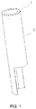
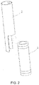
- a heater according to the first embodiment of the present application is as shown in FIG. 1 to FIG. 3 .
- the heater includes a base 1, a conductive module 11, an infrared electrothermal coating 12 and a flexible printed circuit board 2.
- the base 1 has a first end and a second end which are opposite to each other, and the base 1 extends in the longitudinal direction between the first end and the second end, and the base 1 is hollow inside with a cavity for containing aerosol-forming matrix formed therein.
- the base 1 may have shapes of cylinder, prismoid or other columns.
- the base 1 is preferably cylindrical, then the cavity is a cylindrical hole penetrating through the middle of the base 1, and the inner diameter of the hole is slightly larger than the outer diameter of aerosol-forming articles or smoking articles, so that the aerosol-forming articles or smoking articles can be easily placed and heated in the cavity.
- the base 1 may be made of high-temperature resistant and transparent materials such as quartz glass, ceramics or mica; or the base 1 may be made of other materials with higher infrared transmittance, such as high-temperature resistant materials with infrared transmittance above 95%, and this is not particularly limited in the present application.
- the aerosol-forming matrix is a matrix that can release volatile compounds which are capable of forming aerosol. Such volatile compounds may be released by heating the aerosol-forming matrix.
- the aerosol-forming matrix may be solid or liquid or comprise solid and liquid components.
- the aerosol-forming matrix may be adsorbed, coated, impregnated or otherwise loaded on a carrier or support.
- the aerosol-forming matrix may conveniently be part of an aerosol-forming article or a smoking article.
- the aerosol-forming matrix may comprise nicotine.
- the aerosol-forming matrix may comprise tobacco, for example, a tobacco-containing material containing volatile compounds with tobacco aroma, and the volatile compounds with tobacco aroma are released from the aerosol-forming matrix when they are heated.
- a preferred aerosol-forming matrix may comprise a homogeneous tobacco material, such as deciduous tobacco.
- the aerosol-forming matrix may comprise at least one aerosol-forming agent, and the aerosol-forming agent may be any suitable known compound or mixture of compounds. During use, the compound or mixture of compounds is conducive to the formation of dense and stable aerosol, and is basically resistant to thermal degradation at the operating temperature of the aerosol generating system.
- Suitable aerosol forming agents are well known in the art and comprise, but not limited to, polyols such as triethylene glycol, 1,3-butanediol and glycerol; esters of polyols, such as glycerin mono-, di-or triacetate; and fatty acid esters of mono-, di-or polycarboxylic acids, such as dimethyl dodecanedioate and dimethyl tetradecanedioate.
- the preferred aerosol forming agent is polyhydric alcohol or a mixture thereof, such as triethylene glycol, 1,3-butanediol and the most preferred glycerine.
- the infrared electrothermal coating 12 is coated on the surface of the base 1.
- the infrared electrothermal coating 12 may be coated on the outer surface of the base 1 or the inner surface of the base 1.
- the infrared electrothermal coating 12 is coated on the outer surface of the base 1.
- the infrared electrothermal coating 12 can generate heat energy when it is powered on, and then generate infrared rays of a certain wavelength, e.g., far infrared rays of 8 ⁇ m to 15 ⁇ m.
- a certain wavelength e.g., far infrared rays of 8 ⁇ m to 15 ⁇ m.
- the wavelength of the infrared rays matches the absorption wavelength of the aerosol-forming matrix, the energy of infrared rays is easily absorbed by the aerosol-forming matrix.
- the wavelength of the infrared rays is not limited, the infrared rays with the wavelength of 0.75 ⁇ m to 1000 ⁇ m are possible, and far infrared rays with the wavelength of 1.5 ⁇ m to 400 ⁇ m are preferred.
- the infrared electrothermal coating 12 is preferably made of far infrared electrothermal ink, ceramic powder and inorganic adhesive, which are stirred fully and uniformly and printed on the outer surface of the base 1, and then dried and cured for a certain time.
- the thickness of the infrared electrothermal coating 12 is 30 ⁇ m to 50 ⁇ m.
- the infrared electrothermal coating 12 may also be made of tin tetrachloride, tin oxide, antimony trichloride, titanium tetrachloride and anhydrous copper sulfate, which are mixed and stirred at a certain proportion and then coated on the outer surface of the base 1.
- the infrared electrothermal coating 12 is one of a silicon carbide ceramic layer, a carbon fiber composite layer, a zirconium titanium oxide ceramic layer, a zirconium titanium nitride ceramic layer, a zirconium titanium boride ceramic layer, a zirconium titanium carbide ceramic layer, an iron oxide ceramic layer, an iron nitride ceramic layer, an iron boride ceramic layer, an iron carbide ceramic layer, a rare earth oxide ceramic layer, a rare earth nitride ceramic layer, a rare earth boride ceramic layer, a rare earth carbide ceramic layer, a nickel cobalt oxide ceramic layer, a nickel cobalt nitride ceramic layer, a nickel cobalt boride ceramic layer, a nickel cobalt carbide ceramic layer or a high-silica zeolite ceramic layer.
- the infrared electrothermal coating 12 may also be a coating of other materials currently available.
- the heater further includes a protective layer (not shown in the figure) coated on the infrared electrothermal coating 12 and/or a protective structure provided on the infrared electrothermal coating 12.
- the protective layer may be one of a polytetrafluoroethylene layer and a glaze layer or a combination of the polytetrafluoroethylene layer and the glaze layer, or a protective layer made of other high-temperature resistant materials.
- the protective structure may be an assembly or component that separates the aerosol-forming article or smoking article from the infrared electrothermal coating 12, and there may be a gap between the protective structure and the infrared electrothermal coating 12 or the aerosol-forming article.
- the protective layer and/or protective structure can prevent the wear of the infrared electrothermal coating 12 caused by, for example, the movement of the aerosol-forming article (e.g., a cigarette) into or out of the cavity.
- the conductive module 11 includes a first conductive portion 111 and a second conductive portion 112 disposed on the base 1. Both the first conductive portion 111 and the second conductive portion 112 are at least partially and electrically connected with the infrared electrothermal coating 12, so that current can flow from one conductive portion to the other conductive portion through the infrared electrothermal coating 12.
- the polarities of the first conductive portion 111 and the second conductive portion 112 are opposite.
- the first conductive portion 111 is a positive electrode
- the second conductive portion 112 is a negative electrode
- the first conductive portion 111 is a negative electrode
- the second conductive portion 112 is a positive electrode.
- the infrared electrothermal coating 12 is coated on the outer surface of the base 1, the first conductive portion 111 is arranged on the outer surface of the base 1 near the first end, and the second conductive portion 112 is arranged on the outer surface of the base 1 near the second end. If the infrared electrothermal coating 12 is coated on the inner surface of the base 1, the conductive module 11 may also be arranged on the inner surface of the base 1 or span the inner and outer surfaces of the base 1.
- both the first conductive portion 111 and the second conductive portion 112 are annular (annular conductive portions).
- the first conductive portion 111 and the second conductive portion 112 may be annular conductive coatings coated on the outer surface of the base 1 near the first end and the second end.
- the conductive coatings may be metal coatings or conductive tapes, and the metal coatings may comprise silver, gold, palladium, platinum, copper, nickel, molybdenum, tungsten, niobium or an alloy material of the above metals.
- the first conductive portion 111 and the second conductive portion 112 may also be annular conductive sheets sleeved on the outer surface of the base 1 near the first end and the second end, and the conductive sheets are metal conductive sheets, such as copper sheets, steel sheets or the like.
- the conductive module 11 includes a first conductive portion 111, a second conductive portion 112 and a third conductive portion 113.
- the first conductive portion 111 and the second conductive portion 112 are similar to those shown in FIG. 3 , and reference may be made to the above description.
- the third conductive portion 113 is arranged on the outer surface of the base 1 between the first conductive portion 111 and the second conductive portion 112, and the third conductive portion 113 is electrically connected with the infrared electrothermal coating 12.
- the third conductive portion 113 divides the infrared electrothermal coating 12 into two heating areas (labeled as 121 and 122 in the figure) along the longitudinal direction of the base 1, thereby the aerosol-forming matrix in the cavity is heated by segmented.
- the segmented heating for the aerosol-forming matrix in the cavity can be realized by controlling the first conductive portion 111, the second conductive portion 112 and the third conductive portion 113 to be turned on or turned off.
- the conductive module 11 includes a first conductive portion 111, a second conductive portion 112, a third conductive portion 113 and a fourth conductive portion 114.
- the first conductive portion 111 and the second conductive portion 112 are similar to those in FIG. 3 , and reference may be made to the above description.
- the third conductive portion 113 extends from the second conductive portion 112 along the longitudinal direction of the base 1 (the longitudinal direction toward the first conductive portion 111), and the fourth conductive portion 114 extends from the first conductive portion 111 along the longitudinal direction of the base 1 (the longitudinal direction toward the second conductive portion 112).
- both the third conductive portion 113 and the fourth conductive portion 114 are elongated conductive portions along the longitudinal direction of the base 1.
- the current in this embodiment flows in the circumferential direction of the base 1, thereby shortening the flowing distance of the current in the infrared electrothermal coating 12 and reducing the resistance of the infrared electrothermal coating 12 in the current path.
- the conductive module 11 includes a first conductive portion 111 and a second conductive portion 112. Different from FIG. 3 , both the first conductive portion 111 and the second conductive portion 112 are elongated conductive portions and are arranged along the longitudinal direction of the base 1. As compared to FIG.
- the current in this embodiment also flows in the circumferential direction of the base 1, thereby shortening the flowing distance of the current in the infrared electrothermal coating 12 and reducing the resistance of the infrared electrothermal coating 12 in the current path.
- the flexible printed circuit board 2 includes a flexible substrate 20, a first electrode 21 and a second electrode 22 formed on the flexible substrate 20, and a temperature acquisition module 23 for acquiring the temperature data of the base 1.
- the flexible substrate 20 is fixed on the surface of the base 1, so that the first electrode 21 is electrically connected with the first conductive portion 111, and the second electrode 22 is electrically connected with the second conductive portion 112, and the temperature acquisition module 23 is in contact with or close to a target position on the surface of the base 1.
- the target position is a preset position suitable for acquiring the temperature data of the base 1, and the preset position may be determined by user experience or experimental test.
- the temperature acquisition module 23 is arranged at a position corresponding to area of the infrared electrothermal coating 12.
- the position of the temperature acquisition module 23 is relatively stable, which ensures the consistency of temperature data acquisition and facilitates the control of the heating temperature of the heater.
- the flexible substrate 20 includes a covering part (labeled as A in the figure) covering the surface of the base 1, and an extension part (labeled as B in the figure) not covering the surface of the base 1.
- the extension part B extends from one end of the covering part A along the longitudinal direction away from the base 1.
- the extension part B has a plurality of connecting components 24 for connecting with external elements, and the first electrode 21, the second electrode 22 and the temperature acquisition module 23 are respectively connected with the connecting components 24 through conductive lines.
- the connecting components 24 comprise, but not limited to, solder joints, welding holes, pads, via holes, wiring terminals and other electrically connected components.
- the first electrode 21 and the second electrode 22 may be extended to a position away from the base 1 (e.g., the position where the connecting components 24 are located) through the extension part B and the conductive lines.
- the connecting component 24 is a pad for connecting the main control circuit board 4.
- the main control circuit board 4 is used to control the heating temperature of the heater and manage the battery of the smoking device.
- a plurality of wires are adopted to be directly welded with the main control circuit board 4, but such a practice has the following problems.
- the temperature of the base is relatively high, which is easy to cause the short circuit of sol of the wires and presents a great potential safety hazard.
- the number of solder joints is too large, which increases the welding procedures and increases the risk of wrong welding or wrong connection.
- the adoption of a patch (or pin) 5, of which one end is welded to the pad on the extension part B and the other end is welded to the main control circuit board 4 can prevent the problems in the traditional practice described below and save the space.
- the covering part A after being curled (covering the surface of the base 1, the curling direction may be as indicated by the arrow in the figure), may be formed into a shape adapted to the outer surface of the cylindrical base 1 and cover the entire outer surface of the base 1.
- the width of the covering part A in the spreading direction (the direction opposite to the arrow in the figure) is larger than the width of the extension part B in the spreading direction.
- the first electrode 21 and the second electrode 22 provided on the flexible substrate 20 are both elongated electrode portions in the transverse direction (referring to the transverse direction of the base 1 or the direction indicated by the arrow in the figure).
- both the first electrode 21 and the second electrode 22 form into ring-shaped electrodes, which correspond to the annular conductive portions (the first conductive portion 111 and the second conductive portion 112) in FIG. 3 , so that when the flexible substrate 20 covers the surface of the base 1, the first electrode 21 keeps in contact with the first conductive portion 111 and the second electrode 22 keeps in contact with the second conductive portion 112.
- the first electrode 21 provided on the flexible substrate 20 includes an elongated electrode portion 211 in the transverse direction and an elongated electrode portion 212 (the elongated electrode portion 212 extends from the elongated electrode portion 211 in the longitudinal direction) in the longitudinal direction (referring to the longitudinal direction of the base 1)
- the second electrode 22 includes an elongated electrode portion 221 in the transverse direction and an elongated electrode portion 222 in the longitudinal direction (the elongated electrode portion 222 extends from the elongated electrode portion 221 in the longitudinal direction).
- the elongated electrode portion 211 and the elongated electrode portion 221 form into ring-shaped electrodes, which correspond to the shape of the annular conductive portions (the first conductive portion 111 and the second conductive portion 112) in FIG. 5 .
- the elongated electrode portion 212 and the elongated electrode portion 222 form an elongated electrode in the longitudinal direction, which corresponds to the shapes of the elongated conductive portions (the third conductive portion 113 and the fourth conductive portion 114) in FIG. 5 , so that when the flexible substrate 20 covers the surface of the base 1, the first electrode 21 keeps in contact with the first conductive portion 111 and the second electrode 22 keeps in contact with the second conductive portion 112.
- the electrodes formed on the flexible substrate 20 only have the elongated electrode portion 211 in the transverse direction and the elongated electrode portion 221 in the transverse direction.
- the electrodes formed on the flexible substrate 20 only have the elongated electrode portion 212 in the longitudinal direction and the elongated electrode portion 222 in the longitudinal direction.
- the first electrode 21 and the second electrode 22 provided on the flexible substrate 20 are both elongated electrode portions in the longitudinal direction.
- both the first electrode 21 and the second electrode 22 form into elongated electrodes in the longitudinal direction, which correspond to the shapes of the elongated conductive portions (the first conductive portion 111 and the second conductive portion 112) in FIG. 6 , so that when the flexible substrate 20 covers the surface of the base 1, the first electrode 21 keeps in contact with the first conductive portion 111 and the second electrode 22 keeps in contact with the second conductive portion 112.
- the first electrode 21 and the second electrode 22 provided on the flexible substrate 20 are both elongated electrode portions in the transverse direction. After the flexible substrate 20 is curled, the first electrode 21 and the second electrode 22 form into two arc-shaped electrodes at one end of the base 1.
- the arc-shaped electrodes correspond to the elongated conductive portions (the first conductive portion 111 and the second conductive portion 112) in FIG. 6 , so that when the flexible substrate 20 covers the surface of the base 1, the first electrode 21 keeps in contact with the first conductive portion 111 and the second electrode 22 keeps in contact with the second conductive portion 112.
- both the first conductive portion 111 and the second conductive portion 112 are elongated conductive portions extending from one end to the other end of the base 1 (generally in the form of spiral on the surface of the base 1).
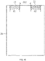
- both the first electrode 21 and the second electrode 22 are provided at one end of the flexible substrate 20.
- the lengths of the two arc-shaped electrodes formed by the first electrode 21 and the second electrode 22 at one end of the base 1 are both smaller than the circumferential distance between the elongated conductive portions, e.g., d1 and d2 in FIG. 10 are smaller than D12 in FIG. 6 .
- the intervals between two arc-shaped electrodes are all larger than the circumferential widths of the elongated conductive portions, e.g., d12 in FIG. 10 is larger than D22 in FIG. 6 .
- first electrode 21 and the second electrode 22 are respectively formed at two ends, the middle or other positions on the flexible substrate 20.
- both the first electrode 21 and the second electrode 22 are elongated electrode portions (approximately in the form of oblique lines, curved lines or other forms on the flexible substrate 2) extending from one end of the flexible substrate 2 to the other end.
- Both the first conductive portion 111 and the second conductive portion 112 are elongated conductive portions extending from one end to the other end of the base 1 (approximately in the form of spiral on the surface of the base 1).
- the electrodes formed by the first electrode 21 and the second electrode 22 correspond to the elongated conductive portions (the first conductive portion 111 and the second conductive portion 112), so that when the flexible substrate 20 covers the surface of the base 1, the first electrode 21 keeps in contact with the first conductive portion 111 and the second electrode 22 keeps in contact with the second conductive portion 112.
- the flexible printed circuit board 2 includes a flexible substrate 20, and a first electrode 21, a second electrode 22 and a third electrode (not shown in the figure) formed on the flexible substrate 20. Reference may be made to the above examples for the shape of the third electrode.
- the first electrode 21 is electrically connected to the first conductive portion 111
- the second electrode 22 is electrically connected to the second conductive portion 112
- the third electrode is electrically connected to the third conductive portion 113.
- the line widths of the first electrode 21 and the second electrode 22 may be set to be 0.2 mm to 3 mm, and preferably, the line widths of the first electrode 21 and the second electrode 22 are set to be 0.2 mm to 1 mm.
- the heater in order to achieve stronger fixation between the first electrode 21 and the first conductive portion 111 as well as between the second electrode 22 and the second conductive portion 112, and ensure the electrical connection between the electrodes and the conductive portions, the heater further includes a first fixing member and a second fixing member (a structure labeled as 3 in FIG. 11 ).
- the first fixing member fixes the first electrode 21 on the first conductive portion 111
- the second fixing member fixes the second electrode 22 on the second conductive portion 112.
- both the first fixing member and the second fixing member are fixing rings with broken notches (labeled as "a” in the figure), and the inner diameter of the fixing rings is smaller than the outer diameter of the base 1.
- the small inner diameter and the broken notch ensure that the fixing ring is sleeved on the base 1 with a certain amount of interference, and ensure that the electrode is closely attached to the conductive portion while maintaining a certain degree of elasticity.
- the flexible substrate 20 is a polyimide thin film, which includes a first polyimide layer 201, a second polyimide layer 203 and a circuit layer 202, wherein at least a part of the circuit layer 202 is positioned between the first polyimide layer 201 and the second polyimide layer 203.
- the temperature acquisition module 23 may be a conductive material with a temperature coefficient of resistance, and the conductive material is disposed on the circuit layer 202.
- the heater further includes a hollow heat insulation pipe.
- the heat insulation pipe covers the periphery of the flexible printed circuit board 2.
- the heat insulation pipe can prevent a large amount of heat from being transferred to the shell of the smoking device, which otherwise would make the user feel hot.
- the inner surface of the heat insulation pipe may further be coated with a reflective coating to reflect the infrared rays emitted by the infrared electrothermal coating 12 on the base 1 back to the interior of the base 1 to heat the aerosol-forming matrix in the cavity, thereby improving the heating efficiency.
- the effect of heat insulation can be achieved to prevent the shell of the smoking device from having an excessively high temperature, which otherwise would reduce the user experience.
- the reflective coating includes at least one of metal and metal oxide.
- the reflective coating may be made of one or more of gold, silver, nickel, aluminum, gold alloy, silver alloy, nickel alloy, aluminum alloy, gold oxide, silver oxide, nickel oxide and aluminum oxide, titanium oxide, zinc oxide and cerium dioxide.
- the thickness of the reflective coating ranges from 0.3 ⁇ m to 200 ⁇ m.
- the heat insulation pipe includes heat insulation material, which may be heat insulation glue, aerogel, aerogel felt, asbestos, aluminum silicate, calcium silicate, diatomaceous earth, zirconia or the like.
- the heat insulation pipe may also include a vacuum heat insulation pipe.
- FIG. 14 to FIG. 15 show a smoking device 100 according to the second embodiment of the present application
- the smoking device 100 includes a housing assembly 6 and the above-mentioned heater, and the heater is arranged within the housing assembly 6.
- the outer surface of a base 1 is provided with an infrared electrothermal coating 12 and a first conductive portion 111 and a second conductive portion 112 electrically connected with the infrared electrothermal coating 12.
- the infrared electrothermal coating 12 may emit infrared rays for radiation heating of the aerosol-forming matrix in the cavity of the base 1.
- the housing assembly 6 includes a shell 61, a fixing housing 62, a fixing member 63 and a bottom cover 64, and the fixing housing 62 and the fixing member 63 are both fixed in the shell 61.
- the fixing member 63 is used for fixing the base 1 and is arranged in the fixing housing 62, and the bottom cover 64 is arranged at one end of the shell 61 and covers the shell 61.
- the fixing member 63 includes an upper fixing seat 631 and a lower fixing seat 632, both of which are arranged in the fixing housing 62.
- the first end and the second end of the base 1 are respectively fixed on the upper fixing seat 631 and the lower fixing seat 632, the bottom cover 64 is convexly provided with an air inlet pipe, and an end of the lower fixing seat 632 facing away from the upper fixing seat 631 is connected with the air inlet pipe.
- the upper fixing seat 631, the base 1, the lower fixing seat 632 and the air inlet pipe are coaxially arranged, and the base 1 is sealed with the upper fixing seat 631 and the lower fixing seat 632, the lower fixing seat 632 is further sealed with the air inlet pipe, and the air inlet pipe communicates with the air outside so as to facilitate smooth air intake when the user sucks.
- the smoking device 100 further includes a flexible printed circuit board 2, fixing rings 3, a main control circuit board 4, a patch 5 and a battery 8.
- the two fixing rings 3 are respectively sleeved on the first end and the second end of the base 1, and the flexible printed circuit board 2 covers the periphery of the base 1.
- One end of the patch 5 is welded to the connecting component 24 (pad) of the flexible printed circuit board 2, and the other end thereof is welded to the main control circuit board 4.
- the fixing housing 62 includes a front housing 621 and a rear housing 622, the front housing 621 is fixedly connected with the rear housing 622, the main control circuit board 4 and the battery 8 are both arranged in the fixing housing 62, the battery 8 is electrically connected with the main control circuit board 4, and the flexible printed circuit board 2 is also electrically connected with the main control circuit board 4.
- a key is convexly arranged on the shell 61, and the infrared electrothermal coating 12 on the outer surface of the base 1 may be turned on or turn off by pressing the key.
- the main control circuit board 4 is further connected with a charging interface, and the charging interface is exposed on the bottom cover 64. Users can charge or upgrade the smoking device 100 through the charging interface to ensure the continuous use of the smoking device 100.
- the smoking device 100 further includes a heat insulation pipe 7, which is arranged in the fixing housing 62 and sleeved outside the base 1.
- the heat insulation pipe 7 can prevent a large amount of heat from being transferred to the shell 61, which otherwise would make the user feel hot.
- a reflective coating may further be coated inside the heat insulation pipe 7, so as to reflect the infrared rays emitted by the infrared electrothermal coating 12 on the base 1 back to the interior of the base 1 to heat the aerosol-forming matrix in the cavity, thereby improving the heating efficiency.
- the flexible printed circuit board 2 is integrated with a NTC temperature sensor for detecting the real-time temperature of the base 1 and transmitting the detected real-time temperature to the main control circuit board 4, and the main control circuit board 4 adjusts the magnitude of the current flowing through the infrared electrothermal coating 12 according to the real-time temperature.
- the main control circuit board 4 controls the battery 8 to output a higher voltage to the conductive module 11, thereby increasing the current fed into the infrared electrothermal coating 12, improving the heating power for the aerosol-forming matrix, and reducing the waiting time for the user to take the first puff.
- the main control circuit board 4 controls the battery 8 to output a normal voltage to the conductive module 11.
- the main control circuit board 4 controls the battery 8 to output a lower voltage to the conductive module 11.
- the main control circuit board 4 controls the battery 8 to stop outputting voltage to the conductive module 11.
Landscapes
- Chemical & Material Sciences (AREA)
- Engineering & Computer Science (AREA)
- Ceramic Engineering (AREA)
- Resistance Heating (AREA)
Abstract
Description
- The present application is based upon and claims priority to
Chinese Patent Application No. 201911185671.9, filed with the Chinese Patent Office on November 27, 2019 - The present application relates to the technical field of smoking sets, and in particular, relates to a heater and a smoking device including the heater.
- Smoking articles such as cigarettes and cigars burn tobacco to produce smoke during use. Attempts have been made to provide substitutes for these tobacco-burning articles by producing products that release compounds without burning. Examples of such products are so-called incombustible products which do not burn when being heated and release compounds by heating instead of burning tobacco.
- A smoking device currently available that does not burn when being heated at a low temperature is mainly coated with a far infrared electrothermal coating and a conductive coating on the outside of a base, the conductive coating needs to be connected with a printed circuit board (PCB) or other elements through external wires, and the far infrared electrothermal coating, after being powered on, emits far infrared rays to penetrate the base and heat the aerosol-forming matrix in the base. Because the far infrared rays have strong penetrability, they can penetrate the periphery of the aerosol-forming matrix and enter the aerosol-forming matrix, so that the aerosol-forming matrix can be heated evenly.
- Disadvantages of the traditional smoking devices lie in that: on the one hand, the wires externally connected with the conductive coating need to be manually arranged and routed, and the assembly efficiency is low; and on the other hand, in the process of heating, the temperature of the base is relatively high, which is easy to cause the short circuit of sol of the wires and presents a great potential safety hazard.
- The present application provides a heater and a smoking device including the heater, which are intended to solve the problems of smoking devices currently available that wires externally connected with a conductive coating need to be manually arranged and routed, and short circuit of sol of the wires occurs easily.
- In the first aspect, the embodiment of the present application discloses a heater. The heater includes a base having a surface; an infrared electrothermal coating, being disposed on the surface of the base; the infrared electrothermal coating being configured to generate infrared radiation to heat aerosol-forming matrix to generate aerosol for smoking; a conductive module, comprising a first conductive portion and a second conductive portion arranged on the base, both the first conductive portion and the second conductive portion being electrically connected with the infrared electrothermal coating; a flexible printed circuit board including a flexible substrate, a first electrode provided on the flexible substrate and a second electrode provided on the flexible substrate; wherein the flexible substrate is fixed on the surface of the base so that the first electrode is electrically connected with the first conductive portion, and the second electrode is electrically connected with the second conductive portion.
- In the second aspect, the embodiment of the present application discloses a smoking device. The smoking device includes a housing assembly and the heater disclosed above; and the heater is arranged in the housing assembly.
- For the heater and the smoking device including the heater according to the present application, the first electrode and the second electrode formed on the flexible printed circuit board are electrically connected with the first conductive portion and the second conductive portion arranged on the base. On the one hand, there is no need for wire connection, which avoids the risk of short circuit of sol of the wires; and there is no need for manual wiring, thereby improving the assembly efficiency. On the other hand, the use of flexible printed circuit board saves the space around the base.
- One or more embodiments are illustrated by the pictures in the corresponding drawings, and these illustrative descriptions do not constitute the limitation of the embodiments. Elements with the same reference numerals in the attached drawings represent similar elements, and unless otherwise stated, the figures in the attached drawings do not constitute scale limitation.
-
FIG. 1 is a schematic view of a heater according to a first embodiment of the present application. -
FIG. 2 is an exploded schematic view ofFIG. 1 . -
FIG. 3 is a schematic view of a base in the heater according to the first embodiment of the present application. -
FIG. 4 is a schematic view of another base in the heater according to the first embodiment of the present application. -
FIG. 5 is a schematic view of another base in the heater according to the first embodiment of the present application. -
FIG. 6 is a schematic view of yet another base in the heater according to the first embodiment of the present application. -
FIG. 7 is a schematic view of a flexible printed circuit board after being unfolded in the heater according to the first embodiment of the present application. -
FIG. 8 is a schematic view of another flexible printed circuit board after being unfolded in the heater according to the first embodiment of the present application. -
FIG. 9 is a schematic view of another flexible printed circuit board after being unfolded in the heater according to the first embodiment of the present application. -
FIG. 10 is a schematic view of yet another flexible printed circuit board after being unfolded in the heater according to the first embodiment of the present application. -
FIG. 11 is a schematic view of a fixing ring in the heater according to the first embodiment of the present application. -
FIG. 12 is a schematic view of the heater and a main control circuit board according to the first embodiment of the present application. -
FIG. 13 is a schematic view of a flexible substrate in the heater according to the first embodiment of the present application. -
FIG. 14 is a schematic view of a smoking device according to a second embodiment of the present application. -
FIG. 15 is an exploded schematic view ofFIG. 14 . - In order to facilitate the understanding of the present application, the present application will be explained in more detail below with reference to the attached drawings and detailed description. It shall be noted that, when an element is expressed as "fixed to" another element, it may be directly on another element, or there may be one or more intervening elements therebetween. When an element is expressed as "connected" to another element, it may be directly connected to another element, or there may be one or more intervening elements therebetween. The terms "up", "down", "left", "right", "inside", "outside" and similar expressions used in this specification are only for the purpose of illustration.
- Unless otherwise defined, all technical and scientific terms used in this specification have the same meanings as commonly understood by those skilled in the art of the present application. In this specification, the terms used in the specification of the present application are only for the purpose of describing specific embodiments, and are not intended to limit the present application. The term "and/or" used in this specification comprises any and all combinations of one or more associated items listed.
- A heater according to the first embodiment of the present application is as shown in
FIG. 1 to FIG. 3 . The heater includes abase 1, aconductive module 11, an infraredelectrothermal coating 12 and a flexible printedcircuit board 2. - The
base 1 has a first end and a second end which are opposite to each other, and thebase 1 extends in the longitudinal direction between the first end and the second end, and thebase 1 is hollow inside with a cavity for containing aerosol-forming matrix formed therein. Thebase 1 may have shapes of cylinder, prismoid or other columns. Thebase 1 is preferably cylindrical, then the cavity is a cylindrical hole penetrating through the middle of thebase 1, and the inner diameter of the hole is slightly larger than the outer diameter of aerosol-forming articles or smoking articles, so that the aerosol-forming articles or smoking articles can be easily placed and heated in the cavity. - The
base 1 may be made of high-temperature resistant and transparent materials such as quartz glass, ceramics or mica; or thebase 1 may be made of other materials with higher infrared transmittance, such as high-temperature resistant materials with infrared transmittance above 95%, and this is not particularly limited in the present application. - The aerosol-forming matrix is a matrix that can release volatile compounds which are capable of forming aerosol. Such volatile compounds may be released by heating the aerosol-forming matrix. The aerosol-forming matrix may be solid or liquid or comprise solid and liquid components. The aerosol-forming matrix may be adsorbed, coated, impregnated or otherwise loaded on a carrier or support. The aerosol-forming matrix may conveniently be part of an aerosol-forming article or a smoking article.
- The aerosol-forming matrix may comprise nicotine. The aerosol-forming matrix may comprise tobacco, for example, a tobacco-containing material containing volatile compounds with tobacco aroma, and the volatile compounds with tobacco aroma are released from the aerosol-forming matrix when they are heated. A preferred aerosol-forming matrix may comprise a homogeneous tobacco material, such as deciduous tobacco. The aerosol-forming matrix may comprise at least one aerosol-forming agent, and the aerosol-forming agent may be any suitable known compound or mixture of compounds. During use, the compound or mixture of compounds is conducive to the formation of dense and stable aerosol, and is basically resistant to thermal degradation at the operating temperature of the aerosol generating system. Suitable aerosol forming agents are well known in the art and comprise, but not limited to, polyols such as triethylene glycol, 1,3-butanediol and glycerol; esters of polyols, such as glycerin mono-, di-or triacetate; and fatty acid esters of mono-, di-or polycarboxylic acids, such as dimethyl dodecanedioate and dimethyl tetradecanedioate. The preferred aerosol forming agent is polyhydric alcohol or a mixture thereof, such as triethylene glycol, 1,3-butanediol and the most preferred glycerine.
- The infrared
electrothermal coating 12 is coated on the surface of thebase 1. The infraredelectrothermal coating 12 may be coated on the outer surface of thebase 1 or the inner surface of thebase 1. Preferably, the infraredelectrothermal coating 12 is coated on the outer surface of thebase 1. - The infrared
electrothermal coating 12 can generate heat energy when it is powered on, and then generate infrared rays of a certain wavelength, e.g., far infrared rays of 8 µm to 15 µm. When the wavelength of the infrared rays matches the absorption wavelength of the aerosol-forming matrix, the energy of infrared rays is easily absorbed by the aerosol-forming matrix. In an embodiment, the wavelength of the infrared rays is not limited, the infrared rays with the wavelength of 0.75 µm to 1000 µm are possible, and far infrared rays with the wavelength of 1.5 µm to 400 µm are preferred. - The infrared
electrothermal coating 12 is preferably made of far infrared electrothermal ink, ceramic powder and inorganic adhesive, which are stirred fully and uniformly and printed on the outer surface of thebase 1, and then dried and cured for a certain time. The thickness of the infraredelectrothermal coating 12 is 30 µm to 50 µm. Alternatively, the infraredelectrothermal coating 12 may also be made of tin tetrachloride, tin oxide, antimony trichloride, titanium tetrachloride and anhydrous copper sulfate, which are mixed and stirred at a certain proportion and then coated on the outer surface of thebase 1. Alternatively, the infraredelectrothermal coating 12 is one of a silicon carbide ceramic layer, a carbon fiber composite layer, a zirconium titanium oxide ceramic layer, a zirconium titanium nitride ceramic layer, a zirconium titanium boride ceramic layer, a zirconium titanium carbide ceramic layer, an iron oxide ceramic layer, an iron nitride ceramic layer, an iron boride ceramic layer, an iron carbide ceramic layer, a rare earth oxide ceramic layer, a rare earth nitride ceramic layer, a rare earth boride ceramic layer, a rare earth carbide ceramic layer, a nickel cobalt oxide ceramic layer, a nickel cobalt nitride ceramic layer, a nickel cobalt boride ceramic layer, a nickel cobalt carbide ceramic layer or a high-silica zeolite ceramic layer. The infraredelectrothermal coating 12 may also be a coating of other materials currently available. - In an embodiment, the heater further includes a protective layer (not shown in the figure) coated on the infrared
electrothermal coating 12 and/or a protective structure provided on the infraredelectrothermal coating 12. The protective layer may be one of a polytetrafluoroethylene layer and a glaze layer or a combination of the polytetrafluoroethylene layer and the glaze layer, or a protective layer made of other high-temperature resistant materials. The protective structure may be an assembly or component that separates the aerosol-forming article or smoking article from the infraredelectrothermal coating 12, and there may be a gap between the protective structure and the infraredelectrothermal coating 12 or the aerosol-forming article. The protective layer and/or protective structure can prevent the wear of the infraredelectrothermal coating 12 caused by, for example, the movement of the aerosol-forming article (e.g., a cigarette) into or out of the cavity. - The
conductive module 11 includes a firstconductive portion 111 and a secondconductive portion 112 disposed on thebase 1. Both the firstconductive portion 111 and the secondconductive portion 112 are at least partially and electrically connected with the infraredelectrothermal coating 12, so that current can flow from one conductive portion to the other conductive portion through the infraredelectrothermal coating 12. The polarities of the firstconductive portion 111 and the secondconductive portion 112 are opposite. For example, the firstconductive portion 111 is a positive electrode, and the secondconductive portion 112 is a negative electrode. Alternatively, the firstconductive portion 111 is a negative electrode, and the secondconductive portion 112 is a positive electrode. Preferably, the infraredelectrothermal coating 12 is coated on the outer surface of thebase 1, the firstconductive portion 111 is arranged on the outer surface of thebase 1 near the first end, and the secondconductive portion 112 is arranged on the outer surface of thebase 1 near the second end. If the infraredelectrothermal coating 12 is coated on the inner surface of thebase 1, theconductive module 11 may also be arranged on the inner surface of thebase 1 or span the inner and outer surfaces of thebase 1. - In this embodiment, both the first
conductive portion 111 and the secondconductive portion 112 are annular (annular conductive portions). The firstconductive portion 111 and the secondconductive portion 112 may be annular conductive coatings coated on the outer surface of thebase 1 near the first end and the second end. The conductive coatings may be metal coatings or conductive tapes, and the metal coatings may comprise silver, gold, palladium, platinum, copper, nickel, molybdenum, tungsten, niobium or an alloy material of the above metals. The firstconductive portion 111 and the secondconductive portion 112 may also be annular conductive sheets sleeved on the outer surface of thebase 1 near the first end and the second end, and the conductive sheets are metal conductive sheets, such as copper sheets, steel sheets or the like. - Referring to
FIG. 4 , in an embodiment, theconductive module 11 includes a firstconductive portion 111, a secondconductive portion 112 and a thirdconductive portion 113. The firstconductive portion 111 and the secondconductive portion 112 are similar to those shown inFIG. 3 , and reference may be made to the above description. The thirdconductive portion 113 is arranged on the outer surface of thebase 1 between the firstconductive portion 111 and the secondconductive portion 112, and the thirdconductive portion 113 is electrically connected with the infraredelectrothermal coating 12. The thirdconductive portion 113 divides the infraredelectrothermal coating 12 into two heating areas (labeled as 121 and 122 in the figure) along the longitudinal direction of thebase 1, thereby the aerosol-forming matrix in the cavity is heated by segmented. In this embodiment, as the infraredelectrothermal coating 12 divided into two heating areas by the thirdconductive portion 113, the segmented heating for the aerosol-forming matrix in the cavity can be realized by controlling the firstconductive portion 111, the secondconductive portion 112 and the thirdconductive portion 113 to be turned on or turned off. - Referring to
FIG. 5 , in another embodiment, theconductive module 11 includes a firstconductive portion 111, a secondconductive portion 112, a thirdconductive portion 113 and a fourthconductive portion 114. The firstconductive portion 111 and the secondconductive portion 112 are similar to those inFIG. 3 , and reference may be made to the above description. The thirdconductive portion 113 extends from the secondconductive portion 112 along the longitudinal direction of the base 1 (the longitudinal direction toward the first conductive portion 111), and the fourthconductive portion 114 extends from the firstconductive portion 111 along the longitudinal direction of the base 1 (the longitudinal direction toward the second conductive portion 112). That is, both the thirdconductive portion 113 and the fourthconductive portion 114 are elongated conductive portions along the longitudinal direction of thebase 1. In this way, as compared toFIG. 3 in which the current flows from the first end to the second end of the base 1 (e.g., flows from the firstconductive portion 111 to the second conductive portion 112) along the longitudinal direction of thebase 1, the current in this embodiment flows in the circumferential direction of thebase 1, thereby shortening the flowing distance of the current in the infraredelectrothermal coating 12 and reducing the resistance of the infraredelectrothermal coating 12 in the current path. - Referring to
FIG. 6 , in another embodiment, theconductive module 11 includes a firstconductive portion 111 and a secondconductive portion 112. Different fromFIG. 3 , both the firstconductive portion 111 and the secondconductive portion 112 are elongated conductive portions and are arranged along the longitudinal direction of thebase 1. As compared toFIG. 3 in which the current flows from the first end to the second end of the base 1 (e.g., flows from the firstconductive portion 111 to the second conductive portion 112) along the longitudinal direction of thebase 1, the current in this embodiment also flows in the circumferential direction of thebase 1, thereby shortening the flowing distance of the current in the infraredelectrothermal coating 12 and reducing the resistance of the infraredelectrothermal coating 12 in the current path. - Referring to
FIG. 7 , the flexible printedcircuit board 2 includes aflexible substrate 20, afirst electrode 21 and asecond electrode 22 formed on theflexible substrate 20, and atemperature acquisition module 23 for acquiring the temperature data of thebase 1. - The
flexible substrate 20 is fixed on the surface of thebase 1, so that thefirst electrode 21 is electrically connected with the firstconductive portion 111, and thesecond electrode 22 is electrically connected with the secondconductive portion 112, and thetemperature acquisition module 23 is in contact with or close to a target position on the surface of thebase 1. The target position is a preset position suitable for acquiring the temperature data of thebase 1, and the preset position may be determined by user experience or experimental test. Generally, thetemperature acquisition module 23 is arranged at a position corresponding to area of the infraredelectrothermal coating 12. As thetemperature acquisition module 23 is integrated in the flexible printedcircuit board 2, when the flexible printedcircuit board 2 covers the periphery of thebase 1, the position of thetemperature acquisition module 23 is relatively stable, which ensures the consistency of temperature data acquisition and facilitates the control of the heating temperature of the heater. - The
flexible substrate 20 includes a covering part (labeled as A in the figure) covering the surface of thebase 1, and an extension part (labeled as B in the figure) not covering the surface of thebase 1. The extension part B extends from one end of the covering part A along the longitudinal direction away from thebase 1. The extension part B has a plurality of connectingcomponents 24 for connecting with external elements, and thefirst electrode 21, thesecond electrode 22 and thetemperature acquisition module 23 are respectively connected with the connectingcomponents 24 through conductive lines. The connectingcomponents 24 comprise, but not limited to, solder joints, welding holes, pads, via holes, wiring terminals and other electrically connected components. Thefirst electrode 21 and thesecond electrode 22 may be extended to a position away from the base 1 (e.g., the position where the connectingcomponents 24 are located) through the extension part B and the conductive lines. - For instance, as shown in
FIG. 12 , the connectingcomponent 24 is a pad for connecting the maincontrol circuit board 4. The maincontrol circuit board 4 is used to control the heating temperature of the heater and manage the battery of the smoking device. Traditionally, a plurality of wires are adopted to be directly welded with the maincontrol circuit board 4, but such a practice has the following problems. On the one hand, in the process of heating, the temperature of the base is relatively high, which is easy to cause the short circuit of sol of the wires and presents a great potential safety hazard. On the other hand, the number of solder joints is too large, which increases the welding procedures and increases the risk of wrong welding or wrong connection. In this embodiment, the adoption of a patch (or pin) 5, of which one end is welded to the pad on the extension part B and the other end is welded to the maincontrol circuit board 4 can prevent the problems in the traditional practice described below and save the space. - The covering part A, after being curled (covering the surface of the
base 1, the curling direction may be as indicated by the arrow in the figure), may be formed into a shape adapted to the outer surface of thecylindrical base 1 and cover the entire outer surface of thebase 1. The width of the covering part A in the spreading direction (the direction opposite to the arrow in the figure) is larger than the width of the extension part B in the spreading direction. - It should be noted that in other examples, it is also possible to cover a part of the surface of the
base 1, e.g., cover the infraredelectrothermal coating 12 between the firstconductive portion 111 and the secondconductive portion 112, by the covering part A that is curled. Alternatively, it is also possible to cover only the part A by theflexible substrate 20. - In this embodiment, when the
flexible substrate 20 covers the surface of thebase 1, at least part of the areas of thefirst electrode 21 and the firstconductive portion 111 contact with each other, and at least part of the areas of thesecond electrode 22 and the secondconductive portion 112 contact with each other, thereby ensuring that thefirst electrode 21 keeps electrical contact with the firstconductive portion 111, and thesecond electrode 22 keeps electrical contact with the secondconductive portion 112. The following description is made with reference toFIG. 3 to FIG. 10 . - Referring to
FIG. 3 andFIG. 7 , in this embodiment, thefirst electrode 21 and thesecond electrode 22 provided on theflexible substrate 20 are both elongated electrode portions in the transverse direction (referring to the transverse direction of thebase 1 or the direction indicated by the arrow in the figure). After theflexible substrate 20 is curled, both thefirst electrode 21 and thesecond electrode 22 form into ring-shaped electrodes, which correspond to the annular conductive portions (the firstconductive portion 111 and the second conductive portion 112) inFIG. 3 , so that when theflexible substrate 20 covers the surface of thebase 1, thefirst electrode 21 keeps in contact with the firstconductive portion 111 and thesecond electrode 22 keeps in contact with the secondconductive portion 112. - Referring to
FIG. 5 andFIG. 8 , in an embodiment, thefirst electrode 21 provided on theflexible substrate 20 includes anelongated electrode portion 211 in the transverse direction and an elongated electrode portion 212 (theelongated electrode portion 212 extends from theelongated electrode portion 211 in the longitudinal direction) in the longitudinal direction (referring to the longitudinal direction of the base 1), and thesecond electrode 22 includes anelongated electrode portion 221 in the transverse direction and anelongated electrode portion 222 in the longitudinal direction (theelongated electrode portion 222 extends from theelongated electrode portion 221 in the longitudinal direction). After theflexible substrate 20 is curled, theelongated electrode portion 211 and theelongated electrode portion 221 form into ring-shaped electrodes, which correspond to the shape of the annular conductive portions (the firstconductive portion 111 and the second conductive portion 112) inFIG. 5 . Theelongated electrode portion 212 and theelongated electrode portion 222 form an elongated electrode in the longitudinal direction, which corresponds to the shapes of the elongated conductive portions (the thirdconductive portion 113 and the fourth conductive portion 114) inFIG. 5 , so that when theflexible substrate 20 covers the surface of thebase 1, thefirst electrode 21 keeps in contact with the firstconductive portion 111 and thesecond electrode 22 keeps in contact with the secondconductive portion 112. - It shall be noted that, for the annular conductive portion and the elongated conductive portion shown in
FIG. 8 , it is also feasible that the electrodes formed on theflexible substrate 20 only have the elongatedelectrode portion 211 in the transverse direction and theelongated electrode portion 221 in the transverse direction. Alternatively, it is also feasible that the electrodes formed on theflexible substrate 20 only have the elongatedelectrode portion 212 in the longitudinal direction and theelongated electrode portion 222 in the longitudinal direction. - Referring to
FIG. 6 andFIG. 9 , in an embodiment, thefirst electrode 21 and thesecond electrode 22 provided on theflexible substrate 20 are both elongated electrode portions in the longitudinal direction. After theflexible substrate 20 is curled, both thefirst electrode 21 and thesecond electrode 22 form into elongated electrodes in the longitudinal direction, which correspond to the shapes of the elongated conductive portions (the firstconductive portion 111 and the second conductive portion 112) inFIG. 6 , so that when theflexible substrate 20 covers the surface of thebase 1, thefirst electrode 21 keeps in contact with the firstconductive portion 111 and thesecond electrode 22 keeps in contact with the secondconductive portion 112. - Referring to
FIG. 6 and10 , in an embodiment, thefirst electrode 21 and thesecond electrode 22 provided on theflexible substrate 20 are both elongated electrode portions in the transverse direction. After theflexible substrate 20 is curled, thefirst electrode 21 and thesecond electrode 22 form into two arc-shaped electrodes at one end of thebase 1. The arc-shaped electrodes correspond to the elongated conductive portions (the firstconductive portion 111 and the second conductive portion 112) inFIG. 6 , so that when theflexible substrate 20 covers the surface of thebase 1, thefirst electrode 21 keeps in contact with the firstconductive portion 111 and thesecond electrode 22 keeps in contact with the secondconductive portion 112. It shall be noted that, it is also feasible if both the firstconductive portion 111 and the secondconductive portion 112 are elongated conductive portions extending from one end to the other end of the base 1 (generally in the form of spiral on the surface of the base 1). - In this embodiment, both the
first electrode 21 and thesecond electrode 22 are provided at one end of theflexible substrate 20. After theflexible substrate 20 is curled, the lengths of the two arc-shaped electrodes formed by thefirst electrode 21 and thesecond electrode 22 at one end of thebase 1 are both smaller than the circumferential distance between the elongated conductive portions, e.g., d1 and d2 inFIG. 10 are smaller than D12 inFIG. 6 . The intervals between two arc-shaped electrodes are all larger than the circumferential widths of the elongated conductive portions, e.g., d12 inFIG. 10 is larger than D22 inFIG. 6 . - It shall be noted that, in other embodiment, it is also feasible that the
first electrode 21 and thesecond electrode 22 are respectively formed at two ends, the middle or other positions on theflexible substrate 20. - In an example (not shown in the figure), both the
first electrode 21 and thesecond electrode 22 are elongated electrode portions (approximately in the form of oblique lines, curved lines or other forms on the flexible substrate 2) extending from one end of theflexible substrate 2 to the other end. Both the firstconductive portion 111 and the secondconductive portion 112 are elongated conductive portions extending from one end to the other end of the base 1 (approximately in the form of spiral on the surface of the base 1). - After the
flexible substrate 20 is curled, the electrodes formed by thefirst electrode 21 and the second electrode 22 (which can be electrodes in the form of oblique lines, curved lines and spiral, etc.) correspond to the elongated conductive portions (the firstconductive portion 111 and the second conductive portion 112), so that when theflexible substrate 20 covers the surface of thebase 1, thefirst electrode 21 keeps in contact with the firstconductive portion 111 and thesecond electrode 22 keeps in contact with the secondconductive portion 112. - Referring to
FIG. 4 for appreciation, in one example, the flexible printedcircuit board 2 includes aflexible substrate 20, and afirst electrode 21, asecond electrode 22 and a third electrode (not shown in the figure) formed on theflexible substrate 20. Reference may be made to the above examples for the shape of the third electrode. - When the
flexible substrate 20 covers the surface of thebase 1, thefirst electrode 21 is electrically connected to the firstconductive portion 111, thesecond electrode 22 is electrically connected to the secondconductive portion 112, and the third electrode is electrically connected to the thirdconductive portion 113. - In this embodiment, in order to ensure the heating effect of the heater, a larger current is required to pass through the
first electrode 21 and thesecond electrode 22, so the line widths of thefirst electrode 21 and thesecond electrode 22 may be set to be 0.2 mm to 3 mm, and preferably, the line widths of thefirst electrode 21 and thesecond electrode 22 are set to be 0.2 mm to 1 mm. - Referring to
FIG. 11 , in an embodiment, in order to achieve stronger fixation between thefirst electrode 21 and the firstconductive portion 111 as well as between thesecond electrode 22 and the secondconductive portion 112, and ensure the electrical connection between the electrodes and the conductive portions, the heater further includes a first fixing member and a second fixing member (a structure labeled as 3 inFIG. 11 ). The first fixing member fixes thefirst electrode 21 on the firstconductive portion 111, and the second fixing member fixes thesecond electrode 22 on the secondconductive portion 112. - In this embodiment, both the first fixing member and the second fixing member are fixing rings with broken notches (labeled as "a" in the figure), and the inner diameter of the fixing rings is smaller than the outer diameter of the
base 1. The small inner diameter and the broken notch ensure that the fixing ring is sleeved on thebase 1 with a certain amount of interference, and ensure that the electrode is closely attached to the conductive portion while maintaining a certain degree of elasticity. - Referring to
FIG. 13 , in an embodiment, theflexible substrate 20 is a polyimide thin film, which includes afirst polyimide layer 201, asecond polyimide layer 203 and acircuit layer 202, wherein at least a part of thecircuit layer 202 is positioned between thefirst polyimide layer 201 and thesecond polyimide layer 203. - In this example, the
temperature acquisition module 23 may be a conductive material with a temperature coefficient of resistance, and the conductive material is disposed on thecircuit layer 202. - In an embodiment, the heater further includes a hollow heat insulation pipe.
- The heat insulation pipe covers the periphery of the flexible printed
circuit board 2. The heat insulation pipe can prevent a large amount of heat from being transferred to the shell of the smoking device, which otherwise would make the user feel hot. - In this embodiment, since a phenomenon that heat is diffused by conduction or convection exists for the infrared
electrothermal coating 12, the inner surface of the heat insulation pipe may further be coated with a reflective coating to reflect the infrared rays emitted by the infraredelectrothermal coating 12 on thebase 1 back to the interior of thebase 1 to heat the aerosol-forming matrix in the cavity, thereby improving the heating efficiency. On the other hand, the effect of heat insulation can be achieved to prevent the shell of the smoking device from having an excessively high temperature, which otherwise would reduce the user experience. - In this embodiment, the reflective coating includes at least one of metal and metal oxide. Specifically, the reflective coating may be made of one or more of gold, silver, nickel, aluminum, gold alloy, silver alloy, nickel alloy, aluminum alloy, gold oxide, silver oxide, nickel oxide and aluminum oxide, titanium oxide, zinc oxide and cerium dioxide. The thickness of the reflective coating ranges from 0.3 µm to 200 µm.
- In this embodiment, the heat insulation pipe includes heat insulation material, which may be heat insulation glue, aerogel, aerogel felt, asbestos, aluminum silicate, calcium silicate, diatomaceous earth, zirconia or the like. The heat insulation pipe may also include a vacuum heat insulation pipe.
-
FIG. 14 to FIG. 15 show asmoking device 100 according to the second embodiment of the present application, thesmoking device 100 includes ahousing assembly 6 and the above-mentioned heater, and the heater is arranged within thehousing assembly 6. In thesmoking device 100 according to the second embodiment, the outer surface of abase 1 is provided with an infraredelectrothermal coating 12 and a firstconductive portion 111 and a secondconductive portion 112 electrically connected with the infraredelectrothermal coating 12. The infraredelectrothermal coating 12 may emit infrared rays for radiation heating of the aerosol-forming matrix in the cavity of thebase 1. - The
housing assembly 6 includes ashell 61, a fixinghousing 62, a fixingmember 63 and abottom cover 64, and the fixinghousing 62 and the fixingmember 63 are both fixed in theshell 61. The fixingmember 63 is used for fixing thebase 1 and is arranged in the fixinghousing 62, and thebottom cover 64 is arranged at one end of theshell 61 and covers theshell 61. Specifically, the fixingmember 63 includes an upper fixingseat 631 and alower fixing seat 632, both of which are arranged in the fixinghousing 62. The first end and the second end of thebase 1 are respectively fixed on the upper fixingseat 631 and the lower fixingseat 632, thebottom cover 64 is convexly provided with an air inlet pipe, and an end of the lower fixingseat 632 facing away from the upper fixingseat 631 is connected with the air inlet pipe. The upper fixingseat 631, thebase 1, the lower fixingseat 632 and the air inlet pipe are coaxially arranged, and thebase 1 is sealed with the upper fixingseat 631 and the lower fixingseat 632, the lower fixingseat 632 is further sealed with the air inlet pipe, and the air inlet pipe communicates with the air outside so as to facilitate smooth air intake when the user sucks. - The
smoking device 100 further includes a flexible printedcircuit board 2, fixingrings 3, a maincontrol circuit board 4, apatch 5 and a battery 8. The two fixingrings 3 are respectively sleeved on the first end and the second end of thebase 1, and the flexible printedcircuit board 2 covers the periphery of thebase 1. One end of thepatch 5 is welded to the connecting component 24 (pad) of the flexible printedcircuit board 2, and the other end thereof is welded to the maincontrol circuit board 4. The fixinghousing 62 includes afront housing 621 and arear housing 622, thefront housing 621 is fixedly connected with therear housing 622, the maincontrol circuit board 4 and the battery 8 are both arranged in the fixinghousing 62, the battery 8 is electrically connected with the maincontrol circuit board 4, and the flexible printedcircuit board 2 is also electrically connected with the maincontrol circuit board 4. A key is convexly arranged on theshell 61, and the infraredelectrothermal coating 12 on the outer surface of thebase 1 may be turned on or turn off by pressing the key. The maincontrol circuit board 4 is further connected with a charging interface, and the charging interface is exposed on thebottom cover 64. Users can charge or upgrade thesmoking device 100 through the charging interface to ensure the continuous use of thesmoking device 100. - The
smoking device 100 further includes aheat insulation pipe 7, which is arranged in the fixinghousing 62 and sleeved outside thebase 1. Theheat insulation pipe 7 can prevent a large amount of heat from being transferred to theshell 61, which otherwise would make the user feel hot. Specifically, a reflective coating may further be coated inside theheat insulation pipe 7, so as to reflect the infrared rays emitted by the infraredelectrothermal coating 12 on thebase 1 back to the interior of thebase 1 to heat the aerosol-forming matrix in the cavity, thereby improving the heating efficiency. - The flexible printed
circuit board 2 is integrated with a NTC temperature sensor for detecting the real-time temperature of thebase 1 and transmitting the detected real-time temperature to the maincontrol circuit board 4, and the maincontrol circuit board 4 adjusts the magnitude of the current flowing through the infraredelectrothermal coating 12 according to the real-time temperature. Specifically, when it is detected by the NTC temperature sensor that the real-time temperature inside thebase 1 is low, e.g., when it is detected that the temperature inside thebase 1 is lower than 150°C, the maincontrol circuit board 4 controls the battery 8 to output a higher voltage to theconductive module 11, thereby increasing the current fed into the infraredelectrothermal coating 12, improving the heating power for the aerosol-forming matrix, and reducing the waiting time for the user to take the first puff. When it is detected by the NTC temperature sensor that the temperature of thebase 1 is 150°C to 200ºC, the maincontrol circuit board 4 controls the battery 8 to output a normal voltage to theconductive module 11. When it is detected by the NTC temperature sensor that the temperature of thebase 1 is 200ºC to 250ºC, the maincontrol circuit board 4 controls the battery 8 to output a lower voltage to theconductive module 11. When it is detected by the NTC temperature sensor that the temperature inside thebase 1 is above 250ºC, the maincontrol circuit board 4 controls the battery 8 to stop outputting voltage to theconductive module 11. - It shall be noted that, the specification and attached drawings of the present application show the preferred embodiments of the present application. However, the present application may be implemented in many different forms, and it is not limited to the embodiments described in this specification. These embodiments are not intended to form additional limitation on the content of the present application, but are provided for a more thorough and comprehensive understanding of the disclosure of the present application. Moreover, the above technical features continue to be combined with each other to form various embodiments not listed above, all of which are regarded as within the scope described in the specification of the present application. Furthermore, those of ordinary skill in the art can make improvements or changes according to the above description, and all these improvements and changes shall fall within the scope claimed in the appended claims of the present application.
Claims (19)
- A heater comprising:a base having a surface;an infrared electrothermal coating, being disposed on the surface of the base; the infrared electrothermal coating being configured to generate infrared radiation to heat aerosol-forming matrix to generate aerosol for smoking;a conductive module, comprising a first conductive portion and a second conductive portion arranged on the base, both the first conductive portion and the second conductive portion being electrically connected with the infrared electrothermal coating;a flexible printed circuit board, comprising a flexible substrate, a first electrode provided on the flexible substrate and a second electrode provided on the flexible substrate;wherein the flexible substrate is fixed on the surface of the base so that the first electrode is electrically connected with the first conductive portion, and the second electrode is electrically connected with the second conductive portion.
- The heater according to claim 1, wherein the flexible substrate comprises a covering part, which is formed into a shape adapted to the surface of the base and covers at least a part of the surface of the base.
- The heater according to claim 2, wherein the covering part covers the infrared electrothermal coating between the first conductive part and the second conductive part; or, the covering part covers Cover the entire surface of the substrate.
- The heater according to claims 2 or 3, wherein the flexible substrate further comprises an extension part with conductive line so that the first electrode and the second electrode are extended to a position far from the base.
- The heater according to claim 4, wherein the extension part extends from one end of the covering part along a longitudinal direction.
- The heater according to claims 4 or 5, wherein a width of the covering part in the spreading direction of the flexible substrate is larger than the width of the extension part in the spreading direction.
- The heater according to any of claims 4 to 6, where in the flexible printed circuit board further comprises a connecting component for electrically connecting with external elements;
the connecting component is located at the extension part, and the first electrode and the second electrode are electrically connected with the connecting component. - The heater according to any of claims 2 to 7, wherein at least part of the areas of the first electrode and the first conductive portion contact with each other, and at least part of the areas of the second electrode and the second conductive portion contact with each other in response to the flexible substrate covering the surface of the base.
- The heater according to claim 8, wherein the first electrode comprises a first elongated electrode portion, the second electrode comprises a second elongated electrode portion; each of the first conductive portion and the second conductive portion comprises an annular conductive portion;
wherein both the first elongated electrode portion and the second elongated electrode portion are formed into arc-shaped electrodes or ring-shaped electrodes, and electrically connected with the annular conductive portions respectively, in response to the flexible substrate covering the surface of the base. - The heater according to claim 8, wherein the first electrode comprises a third elongated electrode portion, the second electrode comprises a fourth elongated electrode portion; each of the first conductive portion and the second conductive portion comprises an elongated conductive portion;
wherein both the third elongated electrode portion and the fourth elongated electrode portion are formed into arc-shaped electrodes and electrically connected with the elongated conductive portions respectively, in response to the flexible substrate covering the surface of the base. - The heater according to claim 10, wherein both the third elongated electrode portion and the fourth elongated electrode portion are arranged at one end of the flexible substrate.
- The heater according to Claim 11, the lengths of the arc-shaped electrodes are all smaller than the circumferential distance between the elongated conductive portions, and the intervals between the arc-shaped electrodes are all larger than the circumferential width of the elongated conductive portions.
- The heater according to any one of claims 1-12, wherein the line width of the first electrode and the second electrode is 0.2 mm to 3 mm.
- The heater according to any of claim 1 to 13, wherein the flexible substrate is a polyimide thin film, and the polyimide thin film comprises a first polyimide layer, a second polyimide layer and a circuit layer, wherein at least a part of the circuit layer is positioned between the first polyimide layer and the second polyimide layer.
- The heater according to any of claim 1 to 14, wherein the flexible printed circuit board further comprises a temperature acquisition module provided on the flexible substrate, and the temperature acquisition module is configured to acquire temperature data of the base.
- The heater according to any of claims 1 to 15, wherein the conductive module further comprises a third conductive portion positioned between the first conductive portion and the second conductive portion, and the third conductive portion arranged on the base is electrically connected with the infrared electrothermal coating wherein the infrared electrothermal coating divided into two heating areas along the longitudinal direction of the base by the third conductive portion or heating the aerosol-forming matrix by segmented;
wherein the flexible printed circuit board further comprises a third electrode provided on the flexible substrate, and the third electrode is electrically connected with the third conductive portion. - The heater according to any of claims 1 to 16, wherein the heater further comprises a fixing member, which is configured to fix the first electrode on the first conductive portion and/or fix the second electrode on the second conductive portion.
- The heater according to claim 17, wherein the fixing member is a fixing ring with a fracture gap, and the inner diameter of the fixing ring is smaller than the outer diameter of the base.
- A smoking device comprising a housing assembly and the heater according to any of claim 1 to 18; the heater being arranged in the housing assembly.
Applications Claiming Priority (2)
| Application Number | Priority Date | Filing Date | Title |
|---|---|---|---|
| CN201911185671.9A CN112841726B (en) | 2019-11-27 | 2019-11-27 | Heater and smoke apparatus including the heater |
| PCT/CN2020/132369 WO2021104472A1 (en) | 2019-11-27 | 2020-11-27 | Heater and smoking device comprising heater |
Publications (2)
| Publication Number | Publication Date |
|---|---|
| EP4085775A1 true EP4085775A1 (en) | 2022-11-09 |
| EP4085775A4 EP4085775A4 (en) | 2023-12-20 |
Family
ID=75985109
Family Applications (1)
| Application Number | Title | Priority Date | Filing Date |
|---|---|---|---|
| EP20893774.8A Pending EP4085775A4 (en) | 2019-11-27 | 2020-11-27 | HEATING ELEMENT AND SMOKING DEVICE INCLUDING THE HEATING ELEMENT |
Country Status (4)
| Country | Link |
|---|---|
| US (1) | US20220338541A1 (en) |
| EP (1) | EP4085775A4 (en) |
| CN (1) | CN112841726B (en) |
| WO (1) | WO2021104472A1 (en) |
Cited By (3)
| Publication number | Priority date | Publication date | Assignee | Title |
|---|---|---|---|---|
| EP4374721A4 (en) * | 2021-07-23 | 2024-11-27 | Shenzhen Merit Technology Co., Ltd. | HEATING ARRANGEMENT AND AEROSOL GENERATING DEVICE |
| EP4374722A4 (en) * | 2021-07-23 | 2024-11-27 | Shenzhen Merit Technology Co., Ltd. | HEATING ARRANGEMENT AND AEROSOL GENERATING DEVICE |
| EP4437872A4 (en) * | 2021-11-26 | 2025-03-26 | Shenzhen Merit Technology Co., Ltd. | HEATING ASSEMBLY AND AEROSOL GENERATING DEVICE |
Families Citing this family (8)
| Publication number | Priority date | Publication date | Assignee | Title |
|---|---|---|---|---|
| CN113115996A (en) * | 2020-01-15 | 2021-07-16 | 深圳市合元科技有限公司 | Aerosol generating device and infrared emitter |
| CN213604404U (en) | 2020-07-03 | 2021-07-06 | 深圳市合元科技有限公司 | Aerosol generating device and infrared emitter |
| GB202011517D0 (en) * | 2020-07-24 | 2020-09-09 | Nicoventures Trading Ltd | Aerosol provision system |
| CN114145495B (en) * | 2021-11-22 | 2024-05-03 | 南昌大学 | HNB electronic cigarette device heated by far infrared paper |
| JP2024545030A (en) * | 2021-12-15 | 2024-12-05 | ジェイティー インターナショナル エスエイ | Heating chamber assembly for an aerosol generating device - Patent Application 20070123633 |
| WO2023111091A1 (en) * | 2021-12-15 | 2023-06-22 | Jt International Sa | Heating chamber assembly for an aerosol generation device |
| CN121465310A (en) * | 2021-12-24 | 2026-02-06 | 重庆江陶科技有限公司 | Resistance heater for aerosol generating device and aerosol generating device |
| CN115486573A (en) * | 2022-09-16 | 2022-12-20 | 深圳麦时科技有限公司 | Heating assembly, aerosol generating device and aerosol generating system |
Family Cites Families (10)
| Publication number | Priority date | Publication date | Assignee | Title |
|---|---|---|---|---|
| CA2852318A1 (en) * | 2013-09-16 | 2015-03-16 | Cameron Lanning Cormack | Printed battery for electronic personal vaporizer |
| CN104397878B (en) * | 2014-11-21 | 2017-10-27 | 黄金珍 | Heat non-combustion-type electronic smoke atomizer and electronic cigarette |
| DE102016115574B4 (en) * | 2016-08-23 | 2024-06-20 | Schott Ag | Heating elements for electronic cigarettes |
| KR101989855B1 (en) * | 2017-04-18 | 2019-06-17 | 주식회사 아모센스 | heater for electronic cigarette |
| TWI871277B (en) * | 2018-01-18 | 2025-02-01 | 瑞士商菲利浦莫里斯製品股份有限公司 | Heater assembly, aerosol-generating device and aerosol-generating system |
| CN119896360A (en) * | 2019-02-28 | 2025-04-29 | 上海合元深蓝科技有限公司 | Low temperature baking smoking utensils |
| CN110384260B (en) * | 2019-07-04 | 2020-12-08 | 青岛颐中科技有限公司 | A heat-not-burn smoking device |
| CN110384261B (en) * | 2019-07-04 | 2025-02-14 | 青岛颐中科技有限公司 | Heat-not-burn smoking device |
| CN110384264A (en) * | 2019-07-15 | 2019-10-29 | 深圳市合元科技有限公司 | Heater and low-temperature heat smoking set |
| CN211910527U (en) * | 2019-11-27 | 2020-11-13 | 深圳市合元科技有限公司 | Heater and smoking set comprising same |
-
2019
- 2019-11-27 CN CN201911185671.9A patent/CN112841726B/en active Active
-
2020
- 2020-11-27 WO PCT/CN2020/132369 patent/WO2021104472A1/en not_active Ceased
- 2020-11-27 EP EP20893774.8A patent/EP4085775A4/en active Pending
-
2022
- 2022-05-26 US US17/825,442 patent/US20220338541A1/en active Pending
Cited By (3)
| Publication number | Priority date | Publication date | Assignee | Title |
|---|---|---|---|---|
| EP4374721A4 (en) * | 2021-07-23 | 2024-11-27 | Shenzhen Merit Technology Co., Ltd. | HEATING ARRANGEMENT AND AEROSOL GENERATING DEVICE |
| EP4374722A4 (en) * | 2021-07-23 | 2024-11-27 | Shenzhen Merit Technology Co., Ltd. | HEATING ARRANGEMENT AND AEROSOL GENERATING DEVICE |
| EP4437872A4 (en) * | 2021-11-26 | 2025-03-26 | Shenzhen Merit Technology Co., Ltd. | HEATING ASSEMBLY AND AEROSOL GENERATING DEVICE |
Also Published As
| Publication number | Publication date |
|---|---|
| WO2021104472A1 (en) | 2021-06-03 |
| EP4085775A4 (en) | 2023-12-20 |
| CN112841726B (en) | 2025-12-02 |
| CN112841726A (en) | 2021-05-28 |
| US20220338541A1 (en) | 2022-10-27 |
Similar Documents
| Publication | Publication Date | Title |
|---|---|---|
| US20220338541A1 (en) | Heater and smoking device including heater | |
| CN211910527U (en) | Heater and smoking set comprising same | |
| CN213344347U (en) | Heater and smoking article including the same | |
| EP4209137A1 (en) | Aerosol generation apparatus and infrared heater | |
| US20220322743A1 (en) | Heater and smoking device including the heater | |
| KR102865696B1 (en) | A heater and a smoking set including the heater | |
| US12262748B2 (en) | Atomizing device and electronic cigarette | |
| CN112841741B (en) | Heater and smoking set comprising same | |
| EP4529780A1 (en) | Heating assembly and aerosol generating apparatus | |
| EP4190184A1 (en) | Heater and cigarette utensil comprising heater | |
| CN119896360A (en) | Low temperature baking smoking utensils | |
| CN112841740B (en) | Heater and smoking set comprising same | |
| EP4559331A1 (en) | Aerosol generation device and control method therefor, and method for generating aerosols | |
| CN219182821U (en) | Heating element and aerosol generating device | |
| CN213939716U (en) | Carbon nanofiber membrane rapid heating electronic cigarette heating pipe | |
| EP4544937A1 (en) | Heating assembly and aerosol generating apparatus | |
| EP4613132A1 (en) | Heater and manufacturing method therefor, and aerosol generating device | |
| CN223614215U (en) | Heater and aerosol generating device | |
| CN213344352U (en) | Heater and smoking article containing the same | |
| EP4609736A1 (en) | Heater and aerosol generating apparatus | |
| CN121910193A (en) | Heater and its preparation method, aerosol generating device |
Legal Events
| Date | Code | Title | Description |
|---|---|---|---|
| STAA | Information on the status of an ep patent application or granted ep patent |
Free format text: STATUS: THE INTERNATIONAL PUBLICATION HAS BEEN MADE |
|
| PUAI | Public reference made under article 153(3) epc to a published international application that has entered the european phase |
Free format text: ORIGINAL CODE: 0009012 |
|
| STAA | Information on the status of an ep patent application or granted ep patent |
Free format text: STATUS: REQUEST FOR EXAMINATION WAS MADE |
|
| PUAB | Information related to the publication of an a document modified or deleted |
Free format text: ORIGINAL CODE: 0009199EPPU |
|
| PUAI | Public reference made under article 153(3) epc to a published international application that has entered the european phase |
Free format text: ORIGINAL CODE: 0009012 |
|
| 17P | Request for examination filed |
Effective date: 20220609 |
|
| AK | Designated contracting states |
Kind code of ref document: A1 Designated state(s): AL AT BE BG CH CY CZ DE DK EE ES FI FR GB GR HR HU IE IS IT LI LT LU LV MC MK MT NL NO PL PT RO RS SE SI SK SM TR |
|
| DAV | Request for validation of the european patent (deleted) | ||
| DAX | Request for extension of the european patent (deleted) | ||
| REG | Reference to a national code |
Ref country code: DE Ref legal event code: R079 Free format text: PREVIOUS MAIN CLASS: A24F0047000000 Ipc: A24F0040460000 |
|
| A4 | Supplementary search report drawn up and despatched |
Effective date: 20231121 |
|
| RIC1 | Information provided on ipc code assigned before grant |
Ipc: H05B 3/06 20060101ALI20231115BHEP Ipc: H05B 3/46 20060101ALI20231115BHEP Ipc: H05B 3/14 20060101ALI20231115BHEP Ipc: H05B 3/04 20060101ALI20231115BHEP Ipc: A24F 40/46 20200101AFI20231115BHEP |