EP4085770A1 - Tow band for smoking article, filter for smoking article, smoking article, and cartridge for smoking article - Google Patents
Tow band for smoking article, filter for smoking article, smoking article, and cartridge for smoking article Download PDFInfo
- Publication number
- EP4085770A1 EP4085770A1 EP20966187.5A EP20966187A EP4085770A1 EP 4085770 A1 EP4085770 A1 EP 4085770A1 EP 20966187 A EP20966187 A EP 20966187A EP 4085770 A1 EP4085770 A1 EP 4085770A1
- Authority
- EP
- European Patent Office
- Prior art keywords
- band
- smoking article
- filter
- value
- range
- Prior art date
- Legal status (The legal status is an assumption and is not a legal conclusion. Google has not performed a legal analysis and makes no representation as to the accuracy of the status listed.)
- Granted
Links
Images


Classifications
-
- A—HUMAN NECESSITIES
- A24—TOBACCO; CIGARS; CIGARETTES; SIMULATED SMOKING DEVICES; SMOKERS' REQUISITES
- A24D—CIGARS; CIGARETTES; TOBACCO SMOKE FILTERS; MOUTHPIECES OF CIGARS OR CIGARETTES; MANUFACTURE OF TOBACCO SMOKE FILTERS OR MOUTHPIECES
- A24D3/00—Tobacco smoke filters, e.g. filter tips or filtering inserts; Filters specially adapted for simulated smoking devices; Mouthpieces of cigars or cigarettes
- A24D3/06—Use of materials for tobacco smoke filters
- A24D3/08—Use of materials for tobacco smoke filters of organic materials as carrier or major constituent
- A24D3/10—Use of materials for tobacco smoke filters of organic materials as carrier or major constituent of cellulose or cellulose derivatives
-
- A—HUMAN NECESSITIES
- A24—TOBACCO; CIGARS; CIGARETTES; SIMULATED SMOKING DEVICES; SMOKERS' REQUISITES
- A24D—CIGARS; CIGARETTES; TOBACCO SMOKE FILTERS; MOUTHPIECES OF CIGARS OR CIGARETTES; MANUFACTURE OF TOBACCO SMOKE FILTERS OR MOUTHPIECES
- A24D1/00—Cigars; Cigarettes
- A24D1/04—Cigars; Cigarettes with mouthpieces or filter-tips
- A24D1/045—Cigars; Cigarettes with mouthpieces or filter-tips with smoke filter means
-
- A—HUMAN NECESSITIES
- A24—TOBACCO; CIGARS; CIGARETTES; SIMULATED SMOKING DEVICES; SMOKERS' REQUISITES
- A24D—CIGARS; CIGARETTES; TOBACCO SMOKE FILTERS; MOUTHPIECES OF CIGARS OR CIGARETTES; MANUFACTURE OF TOBACCO SMOKE FILTERS OR MOUTHPIECES
- A24D1/00—Cigars; Cigarettes
- A24D1/20—Cigarettes specially adapted for simulated smoking devices
-
- A—HUMAN NECESSITIES
- A24—TOBACCO; CIGARS; CIGARETTES; SIMULATED SMOKING DEVICES; SMOKERS' REQUISITES
- A24D—CIGARS; CIGARETTES; TOBACCO SMOKE FILTERS; MOUTHPIECES OF CIGARS OR CIGARETTES; MANUFACTURE OF TOBACCO SMOKE FILTERS OR MOUTHPIECES
- A24D3/00—Tobacco smoke filters, e.g. filter tips or filtering inserts; Filters specially adapted for simulated smoking devices; Mouthpieces of cigars or cigarettes
- A24D3/02—Manufacture of tobacco smoke filters
- A24D3/0204—Preliminary operations before the filter rod forming process, e.g. crimping, blooming
-
- A—HUMAN NECESSITIES
- A24—TOBACCO; CIGARS; CIGARETTES; SIMULATED SMOKING DEVICES; SMOKERS' REQUISITES
- A24D—CIGARS; CIGARETTES; TOBACCO SMOKE FILTERS; MOUTHPIECES OF CIGARS OR CIGARETTES; MANUFACTURE OF TOBACCO SMOKE FILTERS OR MOUTHPIECES
- A24D3/00—Tobacco smoke filters, e.g. filter tips or filtering inserts; Filters specially adapted for simulated smoking devices; Mouthpieces of cigars or cigarettes
- A24D3/02—Manufacture of tobacco smoke filters
- A24D3/0275—Manufacture of tobacco smoke filters for filters with special features
- A24D3/0279—Manufacture of tobacco smoke filters for filters with special features with tubes
-
- A—HUMAN NECESSITIES
- A24—TOBACCO; CIGARS; CIGARETTES; SIMULATED SMOKING DEVICES; SMOKERS' REQUISITES
- A24D—CIGARS; CIGARETTES; TOBACCO SMOKE FILTERS; MOUTHPIECES OF CIGARS OR CIGARETTES; MANUFACTURE OF TOBACCO SMOKE FILTERS OR MOUTHPIECES
- A24D3/00—Tobacco smoke filters, e.g. filter tips or filtering inserts; Filters specially adapted for simulated smoking devices; Mouthpieces of cigars or cigarettes
- A24D3/04—Tobacco smoke filters characterised by their shape or structure
-
- A—HUMAN NECESSITIES
- A24—TOBACCO; CIGARS; CIGARETTES; SIMULATED SMOKING DEVICES; SMOKERS' REQUISITES
- A24D—CIGARS; CIGARETTES; TOBACCO SMOKE FILTERS; MOUTHPIECES OF CIGARS OR CIGARETTES; MANUFACTURE OF TOBACCO SMOKE FILTERS OR MOUTHPIECES
- A24D3/00—Tobacco smoke filters, e.g. filter tips or filtering inserts; Filters specially adapted for simulated smoking devices; Mouthpieces of cigars or cigarettes
- A24D3/04—Tobacco smoke filters characterised by their shape or structure
- A24D3/043—Tobacco smoke filters characterised by their shape or structure with ventilation means, e.g. air dilution
-
- A—HUMAN NECESSITIES
- A24—TOBACCO; CIGARS; CIGARETTES; SIMULATED SMOKING DEVICES; SMOKERS' REQUISITES
- A24D—CIGARS; CIGARETTES; TOBACCO SMOKE FILTERS; MOUTHPIECES OF CIGARS OR CIGARETTES; MANUFACTURE OF TOBACCO SMOKE FILTERS OR MOUTHPIECES
- A24D3/00—Tobacco smoke filters, e.g. filter tips or filtering inserts; Filters specially adapted for simulated smoking devices; Mouthpieces of cigars or cigarettes
- A24D3/06—Use of materials for tobacco smoke filters
- A24D3/062—Use of materials for tobacco smoke filters characterised by structural features
- A24D3/063—Use of materials for tobacco smoke filters characterised by structural features of the fibers
-
- A—HUMAN NECESSITIES
- A24—TOBACCO; CIGARS; CIGARETTES; SIMULATED SMOKING DEVICES; SMOKERS' REQUISITES
- A24D—CIGARS; CIGARETTES; TOBACCO SMOKE FILTERS; MOUTHPIECES OF CIGARS OR CIGARETTES; MANUFACTURE OF TOBACCO SMOKE FILTERS OR MOUTHPIECES
- A24D3/00—Tobacco smoke filters, e.g. filter tips or filtering inserts; Filters specially adapted for simulated smoking devices; Mouthpieces of cigars or cigarettes
- A24D3/06—Use of materials for tobacco smoke filters
- A24D3/16—Use of materials for tobacco smoke filters of inorganic materials
Definitions
- the present disclosure relates to a band for a smoking article, a filter for a smoking article, a smoking article, and a cartridge for a smoking article.
- TD total fineness (total denier). TD refers to the fineness (grams per 9000 m) of a tow assembly (band).
- FD denier per filament (filament denier). FD refers to the fineness (grams per 9000 m) of a single fiber (one fiber). FD is also referred to as denier per filament.
- Tow a plurality of filament assemblies discharged from a spinneret hole of a cabinet. An end and a yarn are each an aspect of the tow.
- Band which are assemblies of single fibers, discharged from each spinneret hole of a plurality of cabinets are bundled, and the TD is set to a predetermined numerical value.
- the bundled tow in which the TD is set to a predetermined numerical value is crimped.
- This crimped tow is a band. That is, the band has a TD and a number of crimps.
- cellulose acetate fibers are used as a material for a filter for a smoking article used in a combusted smoking article that is ignited and smoked, or a tip used in a cartridge of a heated smoking article that is heated and smoked (hereinafter, both the filter and the tip are also simply referred to as "filter”).
- the cellulose acetate fibers are spun by discharging spinning dope from a spinneret based on dry spinning, for example.
- a band is produced by crimping a plurality of cellulose acetate fibers. This band is opened and molded into a cylindrical shape, and winding paper is wound around the outer periphery. This produces a filter.
- titanium oxide is added as a matting agent or a whitening agent to a spinning dope for spinning cellulose acetate fibers, as disclosed in Patent Document 1, for example.
- a titanium compound is added to the spinning dope for the purpose of improving the spinnability of cellulose acetate fibers.
- One measure for preventing indentation of the filter is to increase the amount of stuffing of the band in the filter, for example.
- the pressure drop (PD) of the filter increases. This reduces ease of sucking through the filter and taste through the filter.
- an object of the present disclosure is to improve the quality of a filter produced using cellulose acetate fibers not substantially containing titanium oxide, by preventing indentation and a reduction in hardness while preventing an increase in pressure drop.
- Equation 2 is described such that the crimp ratio I (%) of the band is derived from the relationship between FD and TD in consideration of the ranges of FD and TD with which indentation can be suppressed when the filter is produced using the band based on the result studied by the inventors of the present application.
- the crimp ratio I (%) of the band is set to a value in a predetermined range according to the relationship between FD and TD of the band. This suppresses excessive crimp in a band in which FD is relatively large and TD is relatively small, for example. This makes it possible to decrease shrinkage of the band after opening.
- the band can be hardly shrunk in the axial direction of the filter with respect to the winding paper.
- indentation of the filter can be prevented. Indentation of the filter can be prevented even without increasing the amount of stuffing of the band in the filter. This makes it possible to prevent pressure drop of the filter from increasing. It is also possible to prevent the appearance of the filter from degrading.
- the FD may have a value in a range from 10 to 30, and TD may have a value in a range from 10000 to 50000.
- FD the rigidity of the cellulose acetate fibers is improved. Therefore, by setting TD to the above value, when the band is stuffed in a cylindrical filter, for example, it is possible to increase the repulsive force that the band gives to the winding paper, while appropriately retaining the pressure drop of the filter. This makes it possible to make the band less slippery in the axial direction of the filter with respect to the winding paper. As a result, indentation can be further prevented.
- the number of crimps per 10 inch length of the surface may be a value in a range from 250 to 350. This makes it possible to retain crimping of the band in a suitable state. Therefore, when a filter is produced using the band, it is possible to produce a filter in which indentation is prevented and pressure drop is appropriately set, at a high quality.
- a filter for a smoking article includes: a filter material including any of the bands described above, the filter material being molded into a cylindrical shape; and winding paper wound around an outer periphery of the filter material, in which indentation of the filter material from an end of the winding paper in an axial direction of the filter material has a value in a range of equal to or less than 1 mm.
- the filter for a smoking article may have a perimeter of a value in a range from 15 mm to 18 mm and TD of a value in a range from 15000 to 20000.
- the filter for a smoking article may have a perimeter of a value in a range from 21 mm to less than 23 mm and TD of a value in a range from 25000 to 30000.
- the filter for a smoking article may have a value in a range from 23.5 mm to 25.5 mm and TD of a value in a range from 30000 to 40000.
- a smoking article includes any of the filters for a smoking article described above, and a base member including tobacco leaf, the base member being molded into a cylindrical shape and disposed on one axial end side of the filter for a smoking article.
- a cartridge for a smoking article includes a base member including tobacco leaf, a hollow member configured such that a constituent generated by heating the base member passes through the hollow member, a coolant that cools the constituent having passed through the hollow member, and a filter material that filters a part of the constituent having passed through the coolant, in which at least any of the hollow member, the coolant, or the filter material includes the band described above.
- FIG. 1 is a schematic view of a cellulose acetate (hereinafter, also referred to as "CA") band production apparatus 1.
- the CA band production apparatus 1 continuously spins CA fibers 61, which is a long fiber, by dry spinning. Using the CA fibers 61, the CA band production apparatus 1 produces a yarn 62, an end 63, and a CA band 64.
- the CA band 64 is a band for a smoking article.
- the CA band production apparatus 1 includes a mixing device 2, a filtering device 3, a spinning unit 4, a lubrication unit 5, godet rolls 6, a crimping apparatus 7, and a drying device 8.
- a spinning dope 60 in which cellulose acetate flakes made of, for example, cellulose diacetate are dissolved in an organic solvent at a predetermined concentration is used.
- This spinning dope 60 does not substantially contain titanium oxide.
- the titanium oxide concentration of the spinning dope 60 has a value in a range where the content of titanium oxide in each CA fiber 61 to be spun is from 0 wt.% to 0.01 wt.%.
- the spinning dope 60 is mixed using the mixing device 2, and then filtered by the filtering device 3.
- the spinning dope 60 having passed through the filtering device 3 is supplied to a spinneret 15 arranged on a cabinet 14 of the spinning unit 4.
- the spinning dope 60 is discharged from a plurality of spinneret holes 15a of the spinneret 15.
- the peripheral edge shape of the spinneret hole 15a is triangular as an example, but is not limited to this.
- the peripheral edge shape of the spinneret hole 15a may be circular as an example.
- the size of the spinneret hole 15a is appropriately set according to the FD of the CA fiber 61 after production.
- the spinning dope 60 discharged from each spinneret hole 15a comes into contact with hot air supplied into the cabinet 14.
- the spinning dope 60 is dried by volatilization of the organic solvent. Due to this, CA fibers 61 as a solid are formed.
- the plurality of CA fibers 61 having passed through one cabinet 14 are collected to form the yarn 62.
- the yarn 62 is wound by the godet rolls 6.
- the yarn 62 is then taken up by a predetermined winding device.
- a plurality of the yarns 62 are accumulated or layered. This causes the plurality of yarns 62 to be collected to form the end (tow) 63, which is a flat assembly of the yarns 62.
- the end 63 has a predetermined TD. The end 63 is conveyed and guided to the crimping apparatus 7.
- the crimping apparatus 7 includes a pair of nip rolls 16, 17 and a stuffing box 18.
- the end 63 is pressed into the stuffing box 18 after nip pressure is applied at nip points of the pair of nip rolls 16, 17. Due to this, the end 63 is crimped to produce the CA band 64.
- the CAband 64 having passed through the crimping apparatus 7 is dried and accumulated by the drying device 8. Thereafter, the CA band 64 is compressed and packed into a packing container 19 in the form of a bale.
- Equation 2 shows that the crimp ratio I (%) of the CA band 64 is set in relation to the FD and the TD of the CA band 64.
- the crimp ratio I (%) is set to a value that falls within an appropriate range in a case where the CA band 64 is used for a filter application while the FD is set to a relatively large value and the TD is set to a relatively small value by satisfying the relationship of Equation 2. That is, the CA band 64 is less likely to be excessively crimped. Due to this, the CA band 64 shrinks less due to crimping after opening. Therefore, when the filter is produced using the CA band 64, the CA band 64 shrinks less in the axial direction of the filter due to crimping even in a case where the amount of stuffing in the filter is not so large.
- the FD of the CA band 64 can be set to any value in a range where Equation 2 is satisfied.
- An example of the FD of the CA band 64 is a value in a range from 10 to 30.
- one of 9.9, 10, 11.8, 19.2, and 20 is an example of the lower limit value of the FD of the CA band 64.
- the TD of the CA band 64 can be set to any value in a range where Equation 2 is satisfied.
- An example of the TD of the CA band 64 is a value in a range from 10000 to 50000.
- one of 10000, 15000, 16800, 17000, 25000, 25700, and 30000 is an example of the lower limit value of the TD of the CA band 64.
- the crimp ratio I (%) is a value in a range from 8.6 to 30.3.
- the crimp ratio I (%) is a value in a range from 41.8 to 63.5.
- the crimp ratio I (%) is a value in a range from 32.6 to 54.3.
- the crimp ratio I (%) is a value in a range from 65.8 to 87.5.
- the number of crimps per 10 inch length of the surface is a value in a range from 250 to 350.
- the number of crimps mentioned here can be measured based on the measurement method described in JP H7-316975 A , for example. That is, a personal computer or an image processing device, for example, is used to convert a captured image of the illuminated surface of the CA band 64 into data with a light amount level of 256 gradations. Then, the number of crimps can be measured by counting, as crimps, peaks having a gray level difference of 10 or greater gradations among the data from which a peak waveform of noise shorter than a cycle of a primary crimp has been removed.
- the crimp ratio I (%) of the CA band 64 is set to a value in a predetermined range according to the relationship between the FD and the TD of the CAband 64. This suppresses excessive crimping in the CA band 64 in which the FD is relatively large and the TD is relatively small, for example. This makes it possible to decrease shrinkage of the CA band 64 after opening. Therefore, even if the CA fibers 61 do not substantially contain titanium oxide, when the filter is produced using the CA band 64, the CA band 64 is less likely to shrink in the axial direction of the filter with respect to the winding paper. As a result, indentation of the filter can be prevented. Indentation of the filter can be prevented even without increasing the amount of stuffing of the CA band 64 in the filter. This makes it possible to prevent an increase in pressure drop of the filter. It is also possible to prevent the appearance of the filter from degrading.
- the FD is a value in a range from 10 to 30 and the TD is a value in a range from 10000 to 50000.
- the rigidity of the CA fibers 61 is improved. Therefore, by setting the TD to the above value, when the CA band 64 is stuffed into a cylindrical filter, for example, it is possible to increase the repulsive force that the CA band 64 gives to the winding paper while appropriately retaining the pressure drop of the filter. This makes it possible to make the CA band 64 less slippery in the axial direction of the filter with respect to the winding paper. As a result, indentation can be further prevented.
- the number of crimps per 10 inch length of the surface is a value in a range from 250 to 350. This makes it possible to retain the crimp of the CA band 64 in a suitable state. Therefore, when a filter is produced using the CA band 64, it is possible to produce a filter in which indentation is prevented and pressure drop is appropriately set, at a high quality.
- FIG. 2 is a schematic view of a filter production apparatus 20 according to an embodiment.
- the filter production apparatus 20 includes a collection ring 21, a first opening unit 22, a guide 23, a second opening unit 24, a pre-tension roll pair 25, a first opening roll pair 26, a second opening roll pair 27, a third opening unit 28, a plasticizer application apparatus 29, a conveying roll pair 30, a transport jet 31, a transport stuffer unit 32, and a cutting device 33.
- the CA band 64 drawn up from inside the packing container 19 passes through the collection ring 21, and then is opened in the width direction by pressurized gas in the first opening unit 22. Thereafter, the CA band 64 is guided by the guide 23. Next, the CA band 64 is opened further in the width direction by pressurized gas in the second opening unit 24, and then sequentially inserted between the pre-tension roll pair 25, between the first opening roll pair 26, and between the second opening roll pair 27. Due to this, the CA band 64 is opened in a conveyance direction.
- the CA band 64 having passed between the second opening roll pair 27 is opened further in the width direction by pressurized gas in the third opening unit 28. Thereafter, a plasticizer is applied to the CA band 64 by the plasticizer application apparatus 29.
- the CA band 64 having passed through the plasticizer application apparatus 29 is inserted between the conveying roll pair 30. Thereafter, the CA band 64 is introduced into the transport jet 31 and carried into the transport stuffer unit 32 by a jet stream.
- the transport stuffer unit 32 has a funnel 41, a tongue 42, and a garniture 43.
- the CA band 64 transported into the transport stuffer unit 32 is wound at the funnel 41 and molded into a cylindrical shape.
- a filter material 65 including the CA band 64 and molded into a cylindrical shape is formed.
- a winding paper 40 is guided toward the filter material 65 by the tongue 42.
- the filter material 65 is conveyed by the garniture 43, and the winding paper 40 is wound and fixed around the outer periphery of the filter material 65.
- the cutting device 33 cuts the filter material 65 into a predetermined dimension. Thus, a plug (rod) 66 is produced. The plug 66 is further cut to produce a filter 67 that includes the filter material 65 including the CA band 64 and the winding paper 40 wound around the outer periphery of the filter material 65 is produced.
- the content of titanium oxide is set to a value in a range from 0 wt.% to 0.01 wt.%, and the crimp ratio I (%) calculated by Equation 1 satisfies the relationship of Equation 2.
- the filter 67 is prevented from indentation.
- the stuffing amount of the CA band 64 is appropriately set, and an appropriate amount of the CAband 64 is used for stuffing. Due to this, the filter 67 has an appropriate pressure drop.
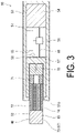
- FIG. 3 is a cross-sectional view of a heated smoking article 50 according to an embodiment.
- This smoking article 50 is a heated tobacco product.
- the smoking article 50 has a long shape and includes a unit 51 and a replaceable cartridge 52.
- the unit 51 includes an enclosure 53, a heating unit 57 that heats a base member 70 (described later) of the cartridge 52, a power supply 54 that is an operation drive source, a display unit 55 that displays information to a user, an operation unit 58 operated by the user, and a control unit 56 that controls the display unit 55 and the heating unit 57.
- the cartridge 52 is an aerosol generation article used in the smoking article 50.
- the cartridge 52 includes the base member 70, a hollow member 71, a coolant 72, and a tip 73.
- the cartridge 52 is molded into a cylindrical shape.
- the base member 70, the hollow member 71, and the filter material 65 are each also molded into a cylindrical shape.
- the hollow member 71, the coolant 72, and the tip 73 are integrally wound from a winding paper 74 in a state of being arranged side by side in the longitudinal direction.
- the cartridge 52 is inserted into an insertion port 51a formed at the other longitudinal end of the unit 51.
- At least any of the hollow member 71, the coolant 72, or the tip 73 includes the CA band 64.
- the materials of the cartridge 52 can be made common. This makes it possible to improve the production efficiency of the cartridge 52.
- the base member 70 includes tobacco leaf.
- the base member 70 contains a tobacco constituent that can be vaporized by heating.
- the base member 70 vaporizes the tobacco constituent by being heated by the heating unit 57 when the smoking article 50 is in use.
- the base member 70 of the present embodiment also contains a flavor constituent such as nicotine that can be vaporized by heating.
- the base member 70 is disposed at one longitudinal end of the cartridge 52 (the insertion side to the insertion port 51a).
- the base member 70 may include, for example, at least any of tobacco rib, expanded tobacco, homogenized tobacco, and herb leaf. These materials may be contained in the base member 70 in the form of a solid being any of fine fragments, a powder, a thread, or a band, in the form of a liquid, or in the form of both a solid and a liquid. When the material is contained as a liquid, the liquid of the material may be enclosed in a capsule. Such a capsule is heated and melted when the smoking article 50 is in use.
- the flavor constituent may be carried on a thermally stable carrier.
- the flavor constituent may be carried on the carrier in the form of a sheet, foam, gel, or slurry.
- the flavor constituent may be dispersed in the base member 70, or may be unevenly distributed at specific positions in the base member 70.
- the hollow member 71 is disposed between the base member 70 and the coolant 72.
- the hollow member 71 is formed into a cylindrical shape.
- the hollow member 71 is configured such that a constituent generated by heating the base member 70 passes through the hollow member 71.
- the hollow member 71 functions as a separator that separates the base member 70 and the coolant 72.
- the hollow member 71 prevents the cartridge 52 from being compressed in the longitudinal direction and the base member 70 from being crushed when the cartridge 52 is inserted into the unit 51 from the insertion port 51a.
- the hollow member 71 of the present embodiment includes the CA band 64.
- the hollow member 71 may contain other materials such as polypropylene.
- the coolant 72 cools the constituent having passed through the hollow member 71.
- the coolant 72 of the present embodiment generates an aerosol (liquid) by cooling and aggregating a gas constituent from the base member 70 that has passed through the hollow member 71.
- the coolant 72 includes, for example, a band-like sheet body wound in the circumferential direction of the cartridge 52 or a band-like sheet body finely folded with each fold extending in the longitudinal direction of the cartridge 52. In the coolant 72, a circulation path for the aerosol is formed by gaps in the sheet body thus wound or finely folded.
- the coolant 72 of the present embodiment includes the CA band 64.
- the coolant 72 may contain one or more of, for example, polyethylene, polypropylene, polyvinyl chloride, high-strength polyethylene terephthalate (polyethylene terephthalate copolymer) (PETG), polylactic acid, and starch-based polyester.
- the sheet body of the coolant 72 may be made of a material of any of porous paper, aluminum foil, or the like.
- the tip 73 filters a part of the constituent having passed through the coolant 72.
- the tip 73 is the filter 67.
- the tip 73 is disposed on the cartridge 52 on the side opposite to the base member 70. The tip 73 is put in the user's mouth when the smoking article 50 is in use.
- the tip 73 filters the aerosol having passed through the coolant 72.
- smoking comfort of a heated smoking article is preferably close to smoking comfort of, for example, a cigarette, which is a combusted smoking article. Therefore, the tip 73 includes the CA band 64 in which the plurality of CA fibers 61 are crimped, similar to a filter of a cigarette, which is a combusted smoking article.
- the dimension of the tip 73 in the insertion direction with respect to the insertion port 51a (hereinafter, referred to as "length dimension of the tip 73") can be appropriately set.
- the length dimension of the tip 73 is set to a value in a range of, for example, from 5 mm to 35 mm.
- One of 5 mm, 7 mm, or 10 mm is an example of the lower limit value of the length dimension of the tip 73, for example.
- One of 17 mm, 20 mm, 25 mm, 28 mm, 30 mm, or 35 mm is an example of the upper limit value of the length dimension of the tip 73.
- the pressure drop of the tip 73 is proportional to the length dimension of the tip 73.
- the pressure drop of the tip 73 can be calculated, for example, by comparing the length dimension of the tip 73 with the length dimension of the filter material 65, which has a known pressure drop.
- the perimeter of the tip 73 can be set as appropriate, and is, as an example, a value in a range of equal to or greater than 15 mm.
- a value in a range from 16 mm to less than 17 mm is an example of the perimeter of the tip 73.
- a value in a range from 21 mm to less than 23 mm is an example of the perimeter of the tip 73.
- a value in a range from 23.5 mm to 25.5 mm is an example of the perimeter of the tip 73.
- the user When using the smoking article 50, the user inserts the cartridge 52 into the unit 51 from the insertion port 51a. Then, the operation unit 58 is operated to turn on the power supply of the unit 51.
- the control unit 56 controls a power supply circuit to heat the heating unit 57 with electric power from the power supply 54. When the heating unit 57 is heated to a predetermined temperature and a predetermined time elapses, the control unit 56 notifies the user that smoking is possible via the display unit 55.
- a gas component from the base member 70 generated by being heated by the heating unit 57 circulates through the hollow member 71. At least some of the gas component having passed through the hollow member 71 is cooled and aggregated when circulating through the gaps of the coolant 72. This generates an aerosol. The aerosol having passed through the coolant 72 is sucked by the user after passing through the tip 73.
- indentation of the tip 73 is prevented. This prevents the hardness of the tip 73 from being reduced due to indentation of the tip 73. This allows the user to experience good usability when holding the tip 73 in the mouth. Further, degradation of the appearance of the cartridge 52 due to the indentation of the tip 73 is prevented.
- an appropriate amount of the CA band 64 is used for stuffing. Therefore, the pressure drop of the tip 73 is set to a value that is not too high. This prevents the tip 73 from excessively filtering the aerosol. Therefore, the user can experience a good taste due to the cartridge 52.
- the stuffing amount of the CA band 64 is stable in the tip 73. Due to this, for example, when a capsule is disposed inside the tip 73, the position of the capsule in the tip 73 is less likely to change due to a variation in density of the CA band 64. Therefore, the capsule can be easily positioned in the tip 73.
- the tip 73 used in the heated smoking article 50 has a shorter length dimension than when used in a combusted smoking article. In this case, when the tip 73 has indentation, the proportion of the indentation in the length direction of the tip 73 increases. Therefore, a defect due to the indentation increases. In the present embodiment, such a defect due to indentation can be satisfactorily prevented.
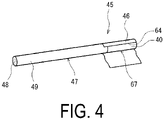
- FIG. 4 is a partially expanded view of a combusted smoking article 45 of an embodiment.
- FIG. 4 illustrates a state in which rolling paper 46 is partially expanded to show the internal configuration of the smoking article 45.
- the smoking article 45 illustrated in FIG. 4 is ignited and smoked.
- the smoking article 45 of the present embodiment is a cigarette.
- the smoking article 45 includes a base member 47, the filter (filter for a smoking article, or cigarette filter) 67, and the rolling paper 46.
- the base member 47 includes a cigarette filler 48 containing tobacco leaf and winding paper 49 wound around an outer periphery of the cigarette filler 48.
- the base member 37 is molded into a cylindrical shape and is disposed at one axial end of the filter 67.
- the rolling paper 46 is wound over the outer periphery of the base member 47 and the filter 67 in a state where the base member 47 and the filter 67 are arranged side by side in the longitudinal direction.
- the smoking article 45 is a thin cigarette, as an example, and has a diameter from 3.0 mm to 6.0 mm.
- As the format of the thin cigarette “super slim” or “ultra super slim” are examples, but the format is not limited to this.
- “demi slim” or “regular” are examples, but the format is not limited to this.
- the smoking article 45 has a perimeter of a value in a range from 15 mm to 18 mm and a TD of a value in a range from 15000 to 20000.
- the smoking article 45 has a perimeter of a value in a range from 21 mm to less than 23 mm and a TD of a value in a range from 25000 to 30000.
- the smoking article 45 has a perimeter of a value in a range from 23.5 mm to 25.5 mm and a TD of a value in a range from 30000 to 40000.
- indentation of the filter material 65 from an end of the winding paper 40 in an axial direction of the filter material 65 has a value in a range of equal to or less than 1 mm.
- the smoking article 45 is prevented from indentation in the filter 67, even when configured as a thin cigarette, for example.
- the filter 67 has appropriate pressure drop. Therefore, ease of smoking the smoking article 45 at the time of smoking is retained. Further, good filtration performance of the filter 67 is obtained. This effect is similarly obtained even when the smoking article 45 is a cigarette having a certain diameter.
- the smoking article 45 may be an article other than a cigarette.
- the filter according to the present modification is disposed at one axial end of a cigar.
- This filter has a similar structure to the tip 73 (filter 67).
- a cigarillo is an example, but the format is not limited to this.
- a CA band and a plug of Examples 1 to 4 and Comparative Examples 1 to 5 were produced by the following procedure. 29 wt.% of CA flakes of cellulose diacetate were dissolved in an organic solvent (acetone and water mixture) to prepare the spinning dope 60 having a titanium oxide concentration of 0 wt.%.
- the CA fiber 61 (Y-shaped cross section) of Example 1 was spun using the plurality of spinnerets 15 formed with the plurality of spinneret holes 15a each having a triangular peripheral edge shape with a side length of 118 ⁇ m. Here, a total of 15 spinnerets 15 were used.
- the spinneret 15 has 145 spinneret holes 15a per spinneret.
- the CA band 64 of Example 1 having a FD of about 10 (actual measurement value 9.9) and a TD of about 17000 (actual measurement value 16800) was produced by adjusting the discharge amount from the spinneret holes 15a, the winding speed of the winding device for winding the spun CA fiber 61, and the peripheral speed of the pair of nip rolls 16 and 17.
- the crimp ratio I (%) of the CA band 64 was set to 25% by adjusting the nip pressure of the pair of nip rolls 16 and 17 and the pressing force of pressing the end 63 into the stuffing box 18.
- the CA band 64 of Example 2 was produced by a similar method to that in Example 1 except that the CA band 64 having a FD of about 12 (actual measurement value 11.8) and a TD of about 25000 (actual measurement value 25700) was spun, and the crimp ratio I (%) was set to 43% based on Equation 2.
- the CA band 64 of Example 3 was produced by a similar method to that in Example 2 except that the crimp ratio I (%) was set to 32%.
- the CA band 64 of Example 4 was produced by a similar method to that in Example 1 except that the CA band 64 having a FD of about 20 (actual measurement value 19.2) and a TD of 27000 (actual measurement value 27000) was spun, and the crimp ratio I (%) thereof was set to 45%.
- the CA band of Comparative Example 1 was produced by a similar method to that in Example 1 except that the crimp ratio I (%) of the CA band was set to 47%.
- the CA band of Comparative Example 2 was produced by a similar method to that in Example 2 except that a mixed solution having a titanium oxide concentration of 0.5 wt.% was used and the crimp ratio I (%) of the CA band was set to 56%.
- the CA band of Comparative Example 3 was produced by a similar method to that in Example 2 except that the crimp ratio I (%) of the CA band was set to 56%.
- the CA band of Comparative Example 4 was produced by a similar method to that in Example 2 except that the crimp ratio I (%) of the CA band was set to 22%.
- the CA band of Comparative Example 5 was produced by a similar method to that in Example 4 except that the crimp ratio I (%) of the CA band was set to 66%.
- the number of crimps per 10 inch length of the CA bands of Examples 1 to 4 and Comparative Examples 1 to 5 were measured by the method described above.
- the length dimensions of the plugs of Examples 1 to 4 and Comparative Examples 1 to 3 and 5 were set to 120 mm.
- the perimeters of the plugs of Example 1 and Comparative Example 1 were set to 16.5 mm.
- the perimeters of the plugs of Examples 2 to 4 and Comparative Examples 2, 3, and 5 were set to 22.5 mm.
- the amount of stuffing of the CA band into the plugs of Example 1 and Comparative Example 1 was set to 0.29 g/rod.
- the amount of stuffing of the CA band into the plugs of Examples 2 to 4 and Comparative Examples 2 and 3 (stuffing amount per plug length (rod length): NTW) was set to 0.47 g/rod.
- the amount of stuffing of the CA band into the plugs of Example 4 and Comparative Example 5 was set to 0.5 g/rod. Further,
- each of Examples 1 to 4 and Comparative Examples 1 to 3 and 5 ten plugs were produced, and an appearance abnormality of the plug was confirmed by the following procedure.
- the plurality of plugs in each of Examples 1 to 4 and Comparative Examples 1 to 3 and 5 were placed on a base surface with an inclination angle of 45 degrees such that the longitudinal direction was along the vertical direction.
- the presence or absence of an appearance abnormality was confirmed using a microscope with a scale capable of measuring the length dimension of the object.
- the indentation depth of each plug (the indentation depth of the filter material from the end of the winding paper in the axial direction of the filter material) was measured.
- a mean value of the measured values was calculated.
- tips were produced by cutting the 10 produced plugs into a length dimension of 7 mm.
- a test cartridge was produced by connecting each of these tips with a remaining portion at which a tip is cut off from a cartridge "HeatStick (registered trademark)" for "iQOS” produced by Philip Morris International Inc.
- the pressure drop (PD) (mmWG) of each aerosol generation component was measured using a filter plug measurer (automatic pressure drop measurer) "QTM” produced by Celulean Ltd. Then, a mean value of the measured values was calculated.
- Tables 1 and 2 show, as mean values, values of the indentation depth of the plug and the pressure drop of the aerosol generation component.
- Example 1 Example 2
- Example 3 Titanium oxide content (wt.%) of CA band 0 0 0 0 FD 9.9 11.8 11.8 19.2
- TD 16800 25700 25700 27000
- Crimp ratio I (%) by Equation 2 14.1 ⁇ I (%) ⁇ 35.8 23.8 ⁇ I (%) ⁇ 45.5 23.8 ⁇ I (%) ⁇ 45.5 33.8 ⁇ I (%) ⁇ 55.5
Landscapes
- Chemical & Material Sciences (AREA)
- Engineering & Computer Science (AREA)
- Materials Engineering (AREA)
- Inorganic Chemistry (AREA)
- Cigarettes, Filters, And Manufacturing Of Filters (AREA)
Abstract
Description
- The present disclosure relates to a band for a smoking article, a filter for a smoking article, a smoking article, and a cartridge for a smoking article.
- This document uses the terms defined as follows.
- TD: total fineness (total denier). TD refers to the fineness (grams per 9000 m) of a tow assembly (band).
- FD: denier per filament (filament denier). FD refers to the fineness (grams per 9000 m) of a single fiber (one fiber). FD is also referred to as denier per filament.
- Tow: a plurality of filament assemblies discharged from a spinneret hole of a cabinet. An end and a yarn are each an aspect of the tow.
- Band: tows, which are assemblies of single fibers, discharged from each spinneret hole of a plurality of cabinets are bundled, and the TD is set to a predetermined numerical value. The bundled tow in which the TD is set to a predetermined numerical value is crimped. This crimped tow is a band. That is, the band has a TD and a number of crimps.
- For example, cellulose acetate fibers are used as a material for a filter for a smoking article used in a combusted smoking article that is ignited and smoked, or a tip used in a cartridge of a heated smoking article that is heated and smoked (hereinafter, both the filter and the tip are also simply referred to as "filter"). The cellulose acetate fibers are spun by discharging spinning dope from a spinneret based on dry spinning, for example. A band is produced by crimping a plurality of cellulose acetate fibers. This band is opened and molded into a cylindrical shape, and winding paper is wound around the outer periphery. This produces a filter.
- In addition to cellulose acetate, titanium oxide is added as a matting agent or a whitening agent to a spinning dope for spinning cellulose acetate fibers, as disclosed in Patent Document 1, for example. For example, as disclosed in
Patent Document 2, a titanium compound is added to the spinning dope for the purpose of improving the spinnability of cellulose acetate fibers. -
- Patent Document 1:
JP H8-500152 T - Patent Document 2:
GB 949505 A - In recent years, there has been a demand to produce a filter using cellulose acetate fibers that do not substantially contain titanium oxide. Cellulose acetate fibers not containing titanium oxide have lower frictional resistance than cellulose acetate fibers containing titanium oxide. For this reason, a filter produced by a band containing cellulose acetate fibers not containing titanium oxide can cause indentation in which the band shrinks relative to the winding paper from its axial end toward the inside. Indentation reduces the hardness of the filter. Indentation also reduces usability when the user holds the filter in the mouth. Further, indentation degrades the appearance of the filter.
- One measure for preventing indentation of the filter is to increase the amount of stuffing of the band in the filter, for example. However, the pressure drop (PD) of the filter increases. This reduces ease of sucking through the filter and taste through the filter.
- Therefore, an object of the present disclosure is to improve the quality of a filter produced using cellulose acetate fibers not substantially containing titanium oxide, by preventing indentation and a reduction in hardness while preventing an increase in pressure drop.
- A band for a smoking article according to an aspect of the present disclosure includes crimped cellulose acetate fibers, content of titanium oxide is set to a value in a range from 0 wt.% to 0.01 wt.%, and a crimp ratio I (%) calculated by Equation 1 satisfies the relationship of
Equation 2,

-
Equation 2 is described such that the crimp ratio I (%) of the band is derived from the relationship between FD and TD in consideration of the ranges of FD and TD with which indentation can be suppressed when the filter is produced using the band based on the result studied by the inventors of the present application. According to the above configuration, the crimp ratio I (%) of the band is set to a value in a predetermined range according to the relationship between FD and TD of the band. This suppresses excessive crimp in a band in which FD is relatively large and TD is relatively small, for example. This makes it possible to decrease shrinkage of the band after opening. Therefore, even if the cellulose acetate fibers do not substantially contain titanium oxide, when the filter is produced using the band, the band can be hardly shrunk in the axial direction of the filter with respect to the winding paper. As a result, indentation of the filter can be prevented. Indentation of the filter can be prevented even without increasing the amount of stuffing of the band in the filter. This makes it possible to prevent pressure drop of the filter from increasing. It is also possible to prevent the appearance of the filter from degrading. - The FD may have a value in a range from 10 to 30, and TD may have a value in a range from 10000 to 50000. By setting FD to the above value, the rigidity of the cellulose acetate fibers is improved. Therefore, by setting TD to the above value, when the band is stuffed in a cylindrical filter, for example, it is possible to increase the repulsive force that the band gives to the winding paper, while appropriately retaining the pressure drop of the filter. This makes it possible to make the band less slippery in the axial direction of the filter with respect to the winding paper. As a result, indentation can be further prevented.
- The number of crimps per 10 inch length of the surface may be a value in a range from 250 to 350. This makes it possible to retain crimping of the band in a suitable state. Therefore, when a filter is produced using the band, it is possible to produce a filter in which indentation is prevented and pressure drop is appropriately set, at a high quality.
- A filter for a smoking article according to an aspect of the present disclosure includes: a filter material including any of the bands described above, the filter material being molded into a cylindrical shape; and winding paper wound around an outer periphery of the filter material, in which indentation of the filter material from an end of the winding paper in an axial direction of the filter material has a value in a range of equal to or less than 1 mm.
- The filter for a smoking article may have a perimeter of a value in a range from 15 mm to 18 mm and TD of a value in a range from 15000 to 20000. Alternatively, the filter for a smoking article may have a perimeter of a value in a range from 21 mm to less than 23 mm and TD of a value in a range from 25000 to 30000. Alternatively, the filter for a smoking article may have a value in a range from 23.5 mm to 25.5 mm and TD of a value in a range from 30000 to 40000.
- A smoking article according to an aspect of the present disclosure includes any of the filters for a smoking article described above, and a base member including tobacco leaf, the base member being molded into a cylindrical shape and disposed on one axial end side of the filter for a smoking article.
- A cartridge for a smoking article according to an aspect of the present disclosure includes a base member including tobacco leaf, a hollow member configured such that a constituent generated by heating the base member passes through the hollow member, a coolant that cools the constituent having passed through the hollow member, and a filter material that filters a part of the constituent having passed through the coolant, in which at least any of the hollow member, the coolant, or the filter material includes the band described above.
- According to the present disclosure, it is possible to improve the quality of a filter produced using cellulose acetate fibers not substantially containing titanium oxide, by preventing indentation and a reduction in hardness while preventing an increase in pressure drop.
-
-
FIG. 1 is a schematic view of a band production apparatus according to an embodiment. -
FIG. 2 is a schematic view of a filter production apparatus according to an embodiment. -
FIG. 3 is a cross-sectional view of a heated smoking article according to an embodiment. -
FIG. 4 is a partially developed view of a combusted smoking article according to an embodiment. - An embodiment will be described with reference to the drawings. "Smoking" mentioned herein includes both a case of igniting and smoking and a case of heating and smoking a base member containing tobacco leaf without igniting.
-
FIG. 1 is a schematic view of a cellulose acetate (hereinafter, also referred to as "CA") band production apparatus 1. The CA band production apparatus 1 continuously spinsCA fibers 61, which is a long fiber, by dry spinning. Using theCA fibers 61, the CA band production apparatus 1 produces ayarn 62, anend 63, and aCA band 64. TheCA band 64 is a band for a smoking article. The CA band production apparatus 1 includes amixing device 2, afiltering device 3, aspinning unit 4, alubrication unit 5, godet rolls 6, a crimping apparatus 7, and adrying device 8. - In the CA band production apparatus 1, a
spinning dope 60 in which cellulose acetate flakes made of, for example, cellulose diacetate are dissolved in an organic solvent at a predetermined concentration is used. Thisspinning dope 60 does not substantially contain titanium oxide. Specifically, the titanium oxide concentration of thespinning dope 60 has a value in a range where the content of titanium oxide in eachCA fiber 61 to be spun is from 0 wt.% to 0.01 wt.%. - The spinning
dope 60 is mixed using themixing device 2, and then filtered by thefiltering device 3. The spinningdope 60 having passed through thefiltering device 3 is supplied to aspinneret 15 arranged on acabinet 14 of thespinning unit 4. The spinningdope 60 is discharged from a plurality ofspinneret holes 15a of thespinneret 15. The peripheral edge shape of thespinneret hole 15a is triangular as an example, but is not limited to this. The peripheral edge shape of thespinneret hole 15a may be circular as an example. The size of thespinneret hole 15a is appropriately set according to the FD of theCA fiber 61 after production. - The spinning
dope 60 discharged from eachspinneret hole 15a comes into contact with hot air supplied into thecabinet 14. The spinningdope 60 is dried by volatilization of the organic solvent. Due to this,CA fibers 61 as a solid are formed. The plurality ofCA fibers 61 having passed through onecabinet 14 are collected to form theyarn 62. After the lubricant is applied by thelubrication unit 5, theyarn 62 is wound by the godet rolls 6. Theyarn 62 is then taken up by a predetermined winding device. - In the CA band production apparatus 1, a plurality of the
yarns 62 are accumulated or layered. This causes the plurality ofyarns 62 to be collected to form the end (tow) 63, which is a flat assembly of theyarns 62. Theend 63 has a predetermined TD. Theend 63 is conveyed and guided to the crimping apparatus 7. - The crimping apparatus 7 includes a pair of nip rolls 16, 17 and a
stuffing box 18. Theend 63 is pressed into thestuffing box 18 after nip pressure is applied at nip points of the pair of nip rolls 16, 17. Due to this, theend 63 is crimped to produce theCA band 64. TheCAband 64 having passed through the crimping apparatus 7 is dried and accumulated by thedrying device 8. Thereafter, theCA band 64 is compressed and packed into a packingcontainer 19 in the form of a bale. - In the
CA band 64, the crimp ratio I (%) calculated by Equation 1 satisfies the relationship ofEquation 2,
CA band 64 in a case where a load of 250 g is applied to theCA band 64 having a length of 250 mm in a direction in which the crimp of theCA fibers 61 is stretched, and L1 is a length of theCA band 64 in a case where a load of 2500 g is applied to theCA band 64 having a length of 250 mm in the same direction,
-
Equation 2 shows that the crimp ratio I (%) of theCA band 64 is set in relation to the FD and the TD of theCA band 64. In theCA band 64, the crimp ratio I (%) is set to a value that falls within an appropriate range in a case where theCA band 64 is used for a filter application while the FD is set to a relatively large value and the TD is set to a relatively small value by satisfying the relationship ofEquation 2. That is, theCA band 64 is less likely to be excessively crimped. Due to this, theCA band 64 shrinks less due to crimping after opening. Therefore, when the filter is produced using theCA band 64, theCA band 64 shrinks less in the axial direction of the filter due to crimping even in a case where the amount of stuffing in the filter is not so large. - The FD of the
CA band 64 can be set to any value in a range whereEquation 2 is satisfied. An example of the FD of theCA band 64 is a value in a range from 10 to 30. As still another example, one of 9.9, 10, 11.8, 19.2, and 20 is an example of the lower limit value of the FD of theCA band 64. One of 25 and 30, whichever is a value larger than the lower limit value, is an example of the upper limit value of the FD of theCA band 64. - The TD of the
CA band 64 can be set to any value in a range whereEquation 2 is satisfied. An example of the TD of theCA band 64 is a value in a range from 10000 to 50000. As another example, one of 10000, 15000, 16800, 17000, 25000, 25700, and 30000 is an example of the lower limit value of the TD of theCA band 64. One of 20000, 30000, 40000, or 50000, whichever is a value larger than the lower limit value, is an example of the upper limit value of the TD of theCAband 64. - In the
CA band 64, when the FD is 10 and the TD is 10000, the crimp ratio I (%) is a value in a range from 8.6 to 30.3. In theCA band 64, when the FD is 10 and the TD is 50000, the crimp ratio I (%) is a value in a range from 41.8 to 63.5. In theCAband 64, when the FD is 30 and the TD is 10000, the crimp ratio I (%) is a value in a range from 32.6 to 54.3. In theCAband 64, when the FD is 30 and the TD is 50000, the crimp ratio I (%) is a value in a range from 65.8 to 87.5. - In the
CA band 64 of the present embodiment, the number of crimps per 10 inch length of the surface is a value in a range from 250 to 350. The number of crimps mentioned here can be measured based on the measurement method described inJP H7-316975 A CA band 64 into data with a light amount level of 256 gradations. Then, the number of crimps can be measured by counting, as crimps, peaks having a gray level difference of 10 or greater gradations among the data from which a peak waveform of noise shorter than a cycle of a primary crimp has been removed. - Thus, according to the above configuration, the crimp ratio I (%) of the
CA band 64 is set to a value in a predetermined range according to the relationship between the FD and the TD of theCAband 64. This suppresses excessive crimping in theCA band 64 in which the FD is relatively large and the TD is relatively small, for example. This makes it possible to decrease shrinkage of theCA band 64 after opening. Therefore, even if theCA fibers 61 do not substantially contain titanium oxide, when the filter is produced using theCA band 64, theCA band 64 is less likely to shrink in the axial direction of the filter with respect to the winding paper. As a result, indentation of the filter can be prevented. Indentation of the filter can be prevented even without increasing the amount of stuffing of theCA band 64 in the filter. This makes it possible to prevent an increase in pressure drop of the filter. It is also possible to prevent the appearance of the filter from degrading. - In the
CA band 64 of the present embodiment, the FD is a value in a range from 10 to 30 and the TD is a value in a range from 10000 to 50000. By setting the FD to the above value, the rigidity of theCA fibers 61 is improved. Therefore, by setting the TD to the above value, when theCA band 64 is stuffed into a cylindrical filter, for example, it is possible to increase the repulsive force that theCA band 64 gives to the winding paper while appropriately retaining the pressure drop of the filter. This makes it possible to make theCA band 64 less slippery in the axial direction of the filter with respect to the winding paper. As a result, indentation can be further prevented. - In the
CA band 64 of the present embodiment, the number of crimps per 10 inch length of the surface is a value in a range from 250 to 350. This makes it possible to retain the crimp of theCA band 64 in a suitable state. Therefore, when a filter is produced using theCA band 64, it is possible to produce a filter in which indentation is prevented and pressure drop is appropriately set, at a high quality. -
FIG. 2 is a schematic view of afilter production apparatus 20 according to an embodiment. As illustrated inFIG. 2 , thefilter production apparatus 20 includes acollection ring 21, afirst opening unit 22, aguide 23, asecond opening unit 24, apre-tension roll pair 25, a firstopening roll pair 26, a secondopening roll pair 27, athird opening unit 28, aplasticizer application apparatus 29, a conveyingroll pair 30, atransport jet 31, atransport stuffer unit 32, and acutting device 33. - In the
filter production apparatus 20, theCA band 64 drawn up from inside the packingcontainer 19 passes through thecollection ring 21, and then is opened in the width direction by pressurized gas in thefirst opening unit 22. Thereafter, theCA band 64 is guided by theguide 23. Next, theCA band 64 is opened further in the width direction by pressurized gas in thesecond opening unit 24, and then sequentially inserted between thepre-tension roll pair 25, between the firstopening roll pair 26, and between the secondopening roll pair 27. Due to this, theCA band 64 is opened in a conveyance direction. - The
CA band 64 having passed between the secondopening roll pair 27 is opened further in the width direction by pressurized gas in thethird opening unit 28. Thereafter, a plasticizer is applied to theCA band 64 by theplasticizer application apparatus 29. TheCA band 64 having passed through theplasticizer application apparatus 29 is inserted between the conveyingroll pair 30. Thereafter, theCA band 64 is introduced into thetransport jet 31 and carried into thetransport stuffer unit 32 by a jet stream. - The
transport stuffer unit 32 has afunnel 41, atongue 42, and agarniture 43. TheCA band 64 transported into thetransport stuffer unit 32 is wound at thefunnel 41 and molded into a cylindrical shape. As a result, afilter material 65 including theCA band 64 and molded into a cylindrical shape is formed. A windingpaper 40 is guided toward thefilter material 65 by thetongue 42. Thefilter material 65 is conveyed by thegarniture 43, and the windingpaper 40 is wound and fixed around the outer periphery of thefilter material 65. - The cutting
device 33 cuts thefilter material 65 into a predetermined dimension. Thus, a plug (rod) 66 is produced. Theplug 66 is further cut to produce afilter 67 that includes thefilter material 65 including theCA band 64 and the windingpaper 40 wound around the outer periphery of thefilter material 65 is produced. - As described above, in the
CA band 64 contained in thefilter 67, the content of titanium oxide is set to a value in a range from 0 wt.% to 0.01 wt.%, and the crimp ratio I (%) calculated by Equation 1 satisfies the relationship ofEquation 2. Thus, thefilter 67 is prevented from indentation. In thefilter 67, the stuffing amount of theCA band 64 is appropriately set, and an appropriate amount of theCAband 64 is used for stuffing. Due to this, thefilter 67 has an appropriate pressure drop. -
FIG. 3 is a cross-sectional view of aheated smoking article 50 according to an embodiment. Thissmoking article 50 is a heated tobacco product. Thesmoking article 50 has a long shape and includes aunit 51 and areplaceable cartridge 52. As an example, theunit 51 includes anenclosure 53, aheating unit 57 that heats a base member 70 (described later) of thecartridge 52, apower supply 54 that is an operation drive source, adisplay unit 55 that displays information to a user, anoperation unit 58 operated by the user, and acontrol unit 56 that controls thedisplay unit 55 and theheating unit 57. - The
cartridge 52 is an aerosol generation article used in thesmoking article 50. Thecartridge 52 includes thebase member 70, ahollow member 71, acoolant 72, and atip 73. As an example, thecartridge 52 is molded into a cylindrical shape. Thebase member 70, thehollow member 71, and thefilter material 65 are each also molded into a cylindrical shape. Thehollow member 71, thecoolant 72, and thetip 73 are integrally wound from a windingpaper 74 in a state of being arranged side by side in the longitudinal direction. When thesmoking article 50 is to be used, thecartridge 52 is inserted into aninsertion port 51a formed at the other longitudinal end of theunit 51. In thecartridge 52 of the present embodiment, at least any of thehollow member 71, thecoolant 72, or thetip 73 includes theCA band 64. By configuring two or more of thecomponents 71 to 73 to include theCA band 64, the materials of thecartridge 52 can be made common. This makes it possible to improve the production efficiency of thecartridge 52. - The
base member 70 includes tobacco leaf. Thebase member 70 contains a tobacco constituent that can be vaporized by heating. Thebase member 70 vaporizes the tobacco constituent by being heated by theheating unit 57 when thesmoking article 50 is in use. Thebase member 70 of the present embodiment also contains a flavor constituent such as nicotine that can be vaporized by heating. Thebase member 70 is disposed at one longitudinal end of the cartridge 52 (the insertion side to theinsertion port 51a). - The
base member 70 may include, for example, at least any of tobacco rib, expanded tobacco, homogenized tobacco, and herb leaf. These materials may be contained in thebase member 70 in the form of a solid being any of fine fragments, a powder, a thread, or a band, in the form of a liquid, or in the form of both a solid and a liquid. When the material is contained as a liquid, the liquid of the material may be enclosed in a capsule. Such a capsule is heated and melted when thesmoking article 50 is in use. - The flavor constituent may be carried on a thermally stable carrier. The flavor constituent may be carried on the carrier in the form of a sheet, foam, gel, or slurry. The flavor constituent may be dispersed in the
base member 70, or may be unevenly distributed at specific positions in thebase member 70. - The
hollow member 71 is disposed between thebase member 70 and thecoolant 72. Thehollow member 71 is formed into a cylindrical shape. Thehollow member 71 is configured such that a constituent generated by heating thebase member 70 passes through thehollow member 71. Thehollow member 71 functions as a separator that separates thebase member 70 and thecoolant 72. Thehollow member 71 prevents thecartridge 52 from being compressed in the longitudinal direction and thebase member 70 from being crushed when thecartridge 52 is inserted into theunit 51 from theinsertion port 51a. Thehollow member 71 of the present embodiment includes theCA band 64. Thehollow member 71 may contain other materials such as polypropylene. - The
coolant 72 cools the constituent having passed through thehollow member 71. Thecoolant 72 of the present embodiment generates an aerosol (liquid) by cooling and aggregating a gas constituent from thebase member 70 that has passed through thehollow member 71. Thecoolant 72 includes, for example, a band-like sheet body wound in the circumferential direction of thecartridge 52 or a band-like sheet body finely folded with each fold extending in the longitudinal direction of thecartridge 52. In thecoolant 72, a circulation path for the aerosol is formed by gaps in the sheet body thus wound or finely folded. - The
coolant 72 of the present embodiment includes theCA band 64. Thecoolant 72 may contain one or more of, for example, polyethylene, polypropylene, polyvinyl chloride, high-strength polyethylene terephthalate (polyethylene terephthalate copolymer) (PETG), polylactic acid, and starch-based polyester. The sheet body of thecoolant 72 may be made of a material of any of porous paper, aluminum foil, or the like. - The
tip 73 filters a part of the constituent having passed through thecoolant 72. Thetip 73 is thefilter 67. Thetip 73 is disposed on thecartridge 52 on the side opposite to thebase member 70. Thetip 73 is put in the user's mouth when thesmoking article 50 is in use. Thetip 73 filters the aerosol having passed through thecoolant 72. - Here, smoking comfort of a heated smoking article is preferably close to smoking comfort of, for example, a cigarette, which is a combusted smoking article. Therefore, the
tip 73 includes theCA band 64 in which the plurality ofCA fibers 61 are crimped, similar to a filter of a cigarette, which is a combusted smoking article. - The dimension of the
tip 73 in the insertion direction with respect to theinsertion port 51a (hereinafter, referred to as "length dimension of thetip 73") can be appropriately set. The length dimension of thetip 73 is set to a value in a range of, for example, from 5 mm to 35 mm. One of 5 mm, 7 mm, or 10 mm is an example of the lower limit value of the length dimension of thetip 73, for example. One of 17 mm, 20 mm, 25 mm, 28 mm, 30 mm, or 35 mm is an example of the upper limit value of the length dimension of thetip 73. - The pressure drop of the
tip 73 is proportional to the length dimension of thetip 73. The pressure drop of thetip 73 can be calculated, for example, by comparing the length dimension of thetip 73 with the length dimension of thefilter material 65, which has a known pressure drop. The perimeter of thetip 73 can be set as appropriate, and is, as an example, a value in a range of equal to or greater than 15 mm. A value in a range from 16 mm to less than 17 mm is an example of the perimeter of thetip 73. As another example, a value in a range from 21 mm to less than 23 mm is an example of the perimeter of thetip 73. As still another example, a value in a range from 23.5 mm to 25.5 mm is an example of the perimeter of thetip 73. - When using the
smoking article 50, the user inserts thecartridge 52 into theunit 51 from theinsertion port 51a. Then, theoperation unit 58 is operated to turn on the power supply of theunit 51. Thecontrol unit 56 controls a power supply circuit to heat theheating unit 57 with electric power from thepower supply 54. When theheating unit 57 is heated to a predetermined temperature and a predetermined time elapses, thecontrol unit 56 notifies the user that smoking is possible via thedisplay unit 55. - When the user holds the
tip 73 in the mouth and inhales, a gas component from thebase member 70 generated by being heated by theheating unit 57 circulates through thehollow member 71. At least some of the gas component having passed through thehollow member 71 is cooled and aggregated when circulating through the gaps of thecoolant 72. This generates an aerosol. The aerosol having passed through thecoolant 72 is sucked by the user after passing through thetip 73. - Here, in the
cartridge 52, indentation of thetip 73 is prevented. This prevents the hardness of thetip 73 from being reduced due to indentation of thetip 73. This allows the user to experience good usability when holding thetip 73 in the mouth. Further, degradation of the appearance of thecartridge 52 due to the indentation of thetip 73 is prevented. In thetip 73, an appropriate amount of theCA band 64 is used for stuffing. Therefore, the pressure drop of thetip 73 is set to a value that is not too high. This prevents thetip 73 from excessively filtering the aerosol. Therefore, the user can experience a good taste due to thecartridge 52. - Since the
CA band 64 is appropriately crimped, the stuffing amount of theCA band 64 is stable in thetip 73. Due to this, for example, when a capsule is disposed inside thetip 73, the position of the capsule in thetip 73 is less likely to change due to a variation in density of theCA band 64. Therefore, the capsule can be easily positioned in thetip 73. There is a case where thetip 73 used in theheated smoking article 50 has a shorter length dimension than when used in a combusted smoking article. In this case, when thetip 73 has indentation, the proportion of the indentation in the length direction of thetip 73 increases. Therefore, a defect due to the indentation increases. In the present embodiment, such a defect due to indentation can be satisfactorily prevented. -
FIG. 4 is a partially expanded view of a combustedsmoking article 45 of an embodiment.FIG. 4 illustrates a state in which rollingpaper 46 is partially expanded to show the internal configuration of thesmoking article 45. Thesmoking article 45 illustrated inFIG. 4 is ignited and smoked. Thesmoking article 45 of the present embodiment is a cigarette. Thesmoking article 45 includes abase member 47, the filter (filter for a smoking article, or cigarette filter) 67, and the rollingpaper 46. Thebase member 47 includes acigarette filler 48 containing tobacco leaf and windingpaper 49 wound around an outer periphery of thecigarette filler 48. The base member 37 is molded into a cylindrical shape and is disposed at one axial end of thefilter 67. The rollingpaper 46 is wound over the outer periphery of thebase member 47 and thefilter 67 in a state where thebase member 47 and thefilter 67 are arranged side by side in the longitudinal direction. Thesmoking article 45 is a thin cigarette, as an example, and has a diameter from 3.0 mm to 6.0 mm. As the format of the thin cigarette, "super slim" or "ultra super slim" are examples, but the format is not limited to this. As another example of the format of the cigarette of thesmoking article 45, "demi slim" or "regular" are examples, but the format is not limited to this. - As an example, the
smoking article 45 has a perimeter of a value in a range from 15 mm to 18 mm and a TD of a value in a range from 15000 to 20000. As another example, thesmoking article 45 has a perimeter of a value in a range from 21 mm to less than 23 mm and a TD of a value in a range from 25000 to 30000. As another example, thesmoking article 45 has a perimeter of a value in a range from 23.5 mm to 25.5 mm and a TD of a value in a range from 30000 to 40000. In thefilter 67, indentation of thefilter material 65 from an end of the windingpaper 40 in an axial direction of thefilter material 65 has a value in a range of equal to or less than 1 mm. Thesmoking article 45 is prevented from indentation in thefilter 67, even when configured as a thin cigarette, for example. Thefilter 67 has appropriate pressure drop. Therefore, ease of smoking thesmoking article 45 at the time of smoking is retained. Further, good filtration performance of thefilter 67 is obtained. This effect is similarly obtained even when thesmoking article 45 is a cigarette having a certain diameter. Thesmoking article 45 may be an article other than a cigarette. - Next, a filter according to a modification of the embodiment will be described. The filter according to the present modification is disposed at one axial end of a cigar. This filter has a similar structure to the tip 73 (filter 67). As the format of a cigar applied with this filter, a cigarillo is an example, but the format is not limited to this.
- Next, a confirmation test will be described. The present disclosure is not limited to Examples 1 to 4 described below.
- A CA band and a plug of Examples 1 to 4 and Comparative Examples 1 to 5 were produced by the following procedure. 29 wt.% of CA flakes of cellulose diacetate were dissolved in an organic solvent (acetone and water mixture) to prepare the
spinning dope 60 having a titanium oxide concentration of 0 wt.%. The CA fiber 61 (Y-shaped cross section) of Example 1 was spun using the plurality ofspinnerets 15 formed with the plurality ofspinneret holes 15a each having a triangular peripheral edge shape with a side length of 118 µm. Here, a total of 15spinnerets 15 were used. Thespinneret 15 has 145spinneret holes 15a per spinneret. - The
CA band 64 of Example 1 having a FD of about 10 (actual measurement value 9.9) and a TD of about 17000 (actual measurement value 16800) was produced by adjusting the discharge amount from thespinneret holes 15a, the winding speed of the winding device for winding the spunCA fiber 61, and the peripheral speed of the pair of nip rolls 16 and 17. In the crimping apparatus 7, the crimp ratio I (%) of theCA band 64 was set to 25% by adjusting the nip pressure of the pair of nip rolls 16 and 17 and the pressing force of pressing theend 63 into thestuffing box 18. - The
CA band 64 of Example 2 was produced by a similar method to that in Example 1 except that theCA band 64 having a FD of about 12 (actual measurement value 11.8) and a TD of about 25000 (actual measurement value 25700) was spun, and the crimp ratio I (%) was set to 43% based onEquation 2. TheCA band 64 of Example 3 was produced by a similar method to that in Example 2 except that the crimp ratio I (%) was set to 32%. TheCA band 64 of Example 4 was produced by a similar method to that in Example 1 except that theCA band 64 having a FD of about 20 (actual measurement value 19.2) and a TD of 27000 (actual measurement value 27000) was spun, and the crimp ratio I (%) thereof was set to 45%. - The CA band of Comparative Example 1 was produced by a similar method to that in Example 1 except that the crimp ratio I (%) of the CA band was set to 47%. The CA band of Comparative Example 2 was produced by a similar method to that in Example 2 except that a mixed solution having a titanium oxide concentration of 0.5 wt.% was used and the crimp ratio I (%) of the CA band was set to 56%. The CA band of Comparative Example 3 was produced by a similar method to that in Example 2 except that the crimp ratio I (%) of the CA band was set to 56%. The CA band of Comparative Example 4 was produced by a similar method to that in Example 2 except that the crimp ratio I (%) of the CA band was set to 22%. The CA band of Comparative Example 5 was produced by a similar method to that in Example 4 except that the crimp ratio I (%) of the CA band was set to 66%. The number of crimps per 10 inch length of the CA bands of Examples 1 to 4 and Comparative Examples 1 to 5 were measured by the method described above.
- Next, using the CA bands of Examples 1 to 4 and Comparative Examples 1 to 5, whether the filter production apparatus 20 (winding machine "KDF-2" produced by Hauni Ltd.) was capable of producing a plug (rod), which is an intermediate body immediately before cutting the tip for electronic cigarette, was confirmed. It was found that, in Comparative Example 4, production of the plug was difficult because crimping of the CA band was insufficient, and problems such as entanglement of the CA fibers in the
filter production apparatus 20 occurred. Therefore, plugs were produced for Examples 1 to 4 and Comparative Examples 1 to 3 and 5. - The length dimensions of the plugs of Examples 1 to 4 and Comparative Examples 1 to 3 and 5 were set to 120 mm. The perimeters of the plugs of Example 1 and Comparative Example 1 were set to 16.5 mm. The perimeters of the plugs of Examples 2 to 4 and Comparative Examples 2, 3, and 5 were set to 22.5 mm. The amount of stuffing of the CA band into the plugs of Example 1 and Comparative Example 1 (stuffing amount per unit length of the plug: NTW) was set to 0.29 g/rod. The amount of stuffing of the CA band into the plugs of Examples 2 to 4 and Comparative Examples 2 and 3 (stuffing amount per plug length (rod length): NTW) was set to 0.47 g/rod. The amount of stuffing of the CA band into the plugs of Example 4 and Comparative Example 5 (stuffing amount per unit length of the tip: NTW) was set to 0.5 g/rod. Further,
- In each of Examples 1 to 4 and Comparative Examples 1 to 3 and 5, ten plugs were produced, and an appearance abnormality of the plug was confirmed by the following procedure. First, the plurality of plugs in each of Examples 1 to 4 and Comparative Examples 1 to 3 and 5 were placed on a base surface with an inclination angle of 45 degrees such that the longitudinal direction was along the vertical direction. In this state, the presence or absence of an appearance abnormality was confirmed using a microscope with a scale capable of measuring the length dimension of the object. Thus, the indentation depth of each plug (the indentation depth of the filter material from the end of the winding paper in the axial direction of the filter material) was measured. Then, a mean value of the measured values was calculated.
- In each of Examples 1 to 4 and Comparative Examples 1 to 3 and 5, tips were produced by cutting the 10 produced plugs into a length dimension of 7 mm. A test cartridge was produced by connecting each of these tips with a remaining portion at which a tip is cut off from a cartridge "HeatStick (registered trademark)" for "iQOS" produced by Philip Morris International Inc. The pressure drop (PD) (mmWG) of each aerosol generation component was measured using a filter plug measurer (automatic pressure drop measurer) "QTM" produced by Celulean Ltd. Then, a mean value of the measured values was calculated. The test results are shown in Tables 1 and 2. Tables 1 and 2 show, as mean values, values of the indentation depth of the plug and the pressure drop of the aerosol generation component.
[Table 1] Example 1 Example 2 Example 3 Example 4 Titanium oxide content (wt.%) of CA band 0 0 0 0 FD 9.9 11.8 11.8 19.2 TD 16800 25700 25700 27000 Crimp ratio I (%) by Equation 214.1 < I (%) < 35.8 23.8 < I (%) < 45.5 23.8 < I (%) < 45.5 33.8 < I (%) < 55.5 Measured crimp ratio I (%) 25 43 32 45 Plug processing possible? Yes Yes Yes Yes PD (mmWG) 355 115 115 79 Appearance abnormality of plug end Indentation 1 mm or less Indentation 1 mm or less Indentation 1 mm or less Indentation 1 mm or less Number of crimps per 10 inch length 300 340 290 300 Stuffing amount of CA band into plug (NTW (g)) 0.29 0.47 0.47 0.5 Plug perimeter (mm) 16.5 22.5 22.5 22.5 [Table 2] Comparative Example 1 Comparative Example 2 Comparative Example 3 Comparative Example 4 Comparative Example 5 Titanium oxide content (wt.%) of CA band 0 0.5 0 0 0 FD 9.9 11.8 11.8 11.8 19.2 TD 16800 25700 25700 25700 27000 Crimp ratio I (%) by Equation 214.1 < I (%) < 35.8 23.8 < I (%) < 45.5 23.8 < I (%) < 45.5 23.8 < I (%) < 45.5 33.8 < I (%) < 55.5 Measured crimp ratio I (%) 47 56 56 22 66 Plug processing possible? Yes Yes Yes No Yes PD (mmWG) 360 120 120 - 81 Appearance abnormality of plug end Indentation 1 mm or greater Indentation 1 mm or less Indentation 1 mm or greater - Indentation 1 mm or greater Number of crimps per 10 inch length 400 400 400 240 400 Stuffing amount of CA band into plug (NTW (g)) 0.29 0.47 0.47 - 0.5 Plug perimeter (mm) 16.5 22.5 22.5 - 22.5 - As shown in Table 1, in Examples 1 to 4, a stuffing amount of the CA band equivalent to that in Comparative Examples 1 to 3 and 5 was set, but it was confirmed that the indentation of the plug was less than that in Comparative Examples 1 to 3 and 5 and the depth of indentation was equal to or less than 1 mm. Due to this, it was confirmed that the plugs of Examples 1 to 4 had a good appearance. In Examples 1 to 4, it was confirmed that the pressure drop of the
tip 73 in thecartridge 52 was appropriately set, and the aerosol of thecartridge 52 was sucked well when thesmoking article 50 was in use. From the above, superiority of Examples 1 to 4 over Comparative Examples 1 to 5 was confirmed. From the tendency indicated by the test results, it is thought that similar excellent results to those of Examples 1 to 5 can be obtained even in a case where the FD of theCA band 64 has a value in a range of greater than 19.2 and equal to or less than 30 and the TD of theCA band 64 has a value in a range of greater than 27000 and equal to or less than 30000. - Note that each of the configurations, combinations thereof, or the like in the embodiments are exemplary, and additions, omissions, replacements, and other changes to the configurations may be made as appropriate without departing from the spirit of the present disclosure. The present disclosure is not limited by the embodiments and is limited only by the claims. Each aspect disclosed in the present specification can be combined with any other feature disclosed herein.
-
- 45 Combusted smoking article
- 50 Heated smoking article
- 52 Cartridge
- 61 CA fiber
- 64, 164 CA band
- 65 Filter material
- 67 Filter (filter for smoking article)
- 70 Base member
- 71 Hollow member
- 72 Coolant
- 73 Tip (filter)
Claims (9)
- A band for a smoking article, comprisinga crimped cellulose acetate fiber, whereincontent of titanium oxide is set to a value in a range from 0 wt.% to 0.01 wt.%, anda crimp ratio I (%) calculated by Equation 1 satisfies a relationship of Equation 2,
 where L0 is a length of the band in a case where a load of 250 g is applied to the band having a length of 250 mm in a direction in which crimp of the cellulose acetate fibers is stretched, and L1 is a length of the band in a case where a load of 2500 g is applied to the band having the length of 250 mm in the direction,
- The band for a smoking article according to claim 1, whereinFD has a value in a range from 10 to 30, andTD has a value in a range from 10000 to 50000.
- The band for a smoking article according to claim 1 or 2, wherein a number of crimps per 10 inch length of a surface is a value in a range from 250 to 350.
- A filter for a smoking article, comprising:a filter material including the band described in any one of claims 1 to 3, the filter material being molded into a cylindrical shape; andwinding paper wound around an outer periphery of the filter material, whereinindentation of the filter material from an end of the winding paper in an axial direction of the filter material has a value in a range of equal to or less than 1 mm.
- The filter for a smoking article according to claim 4, wherein a perimeter has a value in a range from 15 mm to 18 mm, and TD is a value in a range from 15000 to 20000.
- The filter for a smoking article according to claim 4, wherein a perimeter has a value in a range from 21 mm to less than 23 mm, and TD is a value in a range from 25000 to 30000.
- The filter for a smoking article according to claim 4, wherein a perimeter has a value in a range from 23.5 mm to 25.5 mm, and TD is a value in a range from 30000 to 40000.
- A smoking article comprising:the filter for a smoking article described in any one of claims 4 to 7; anda base member including tobacco leaf, the base member being molded into a cylindrical shape and disposed on one axial end side of the filter for a smoking article.
- A cartridge for a smoking article, comprising:a base member including tobacco leaf;a hollow member configured such that a constituent generated by heating the base member passes through the hollow member;a coolant that cools the constituent having passed through the hollow member; anda filter material that filters a part of the constituent having passed through the coolant, whereinat least any of the hollow member, the coolant, or the filter material includes the band described in any of claims 1 to 3.
Applications Claiming Priority (1)
| Application Number | Priority Date | Filing Date | Title |
|---|---|---|---|
| PCT/JP2020/047849 WO2022137322A1 (en) | 2020-12-22 | 2020-12-22 | Tow band for smoking article, filter for smoking article, smoking article, and cartridge for smoking article |
Publications (4)
| Publication Number | Publication Date |
|---|---|
| EP4085770A1 true EP4085770A1 (en) | 2022-11-09 |
| EP4085770A4 EP4085770A4 (en) | 2023-01-18 |
| EP4085770C0 EP4085770C0 (en) | 2024-03-20 |
| EP4085770B1 EP4085770B1 (en) | 2024-03-20 |
Family
ID=82158564
Family Applications (1)
| Application Number | Title | Priority Date | Filing Date |
|---|---|---|---|
| EP20966187.5A Active EP4085770B1 (en) | 2020-12-22 | 2020-12-22 | Tow band for smoking article, filter for smoking article, smoking article, and cartridge for smoking article |
Country Status (4)
| Country | Link |
|---|---|
| EP (1) | EP4085770B1 (en) |
| KR (1) | KR20230116901A (en) |
| PL (1) | PL4085770T3 (en) |
| WO (1) | WO2022137322A1 (en) |
Cited By (1)
| Publication number | Priority date | Publication date | Assignee | Title |
|---|---|---|---|---|
| WO2025113828A1 (en) * | 2022-11-29 | 2025-06-05 | Jt International Sa | A bale of nonwoven material, a method for manufacturing a bale of nonwoven material, and a method for manufacturing a filter |
Family Cites Families (17)
| Publication number | Priority date | Publication date | Assignee | Title |
|---|---|---|---|---|
| US3033698A (en) | 1959-10-23 | 1962-05-08 | Eastman Kodak Co | Cellulose acetate spinning solutions and process of spinning fine denier filaments |
| CA2135798A1 (en) | 1992-05-27 | 1993-12-09 | Charles M. Buchanan | Environmentally non-persistant cellulose ester fibers |
| JPH07316975A (en) | 1994-05-19 | 1995-12-05 | Daicel Chem Ind Ltd | Measurement of crimping characteristics of fiber and apparatus therefor |
| TWI274556B (en) | 1999-03-11 | 2007-03-01 | Japan Tobacco Inc | Biodegradable cellulose acetate structures and tobacco filters |
| DE10121310A1 (en) | 2001-05-02 | 2002-11-28 | Rhodia Acetow Gmbh | Filter tow |
| KR100949505B1 (en) | 2006-06-05 | 2010-03-24 | 엘지디스플레이 주식회사 | Photo device and method |
| TW200936065A (en) | 2008-01-23 | 2009-09-01 | Filtrona Int Ltd | Tobacco smoke filter |
| US20120325233A1 (en) | 2011-06-23 | 2012-12-27 | Eastman Chemical Company | Cellulose esters having mixed-phase titanium dioxide particles for improved degradation |
| US20130115452A1 (en) | 2011-11-03 | 2013-05-09 | Celanese Acetate Llc | High Denier Per Filament and Low Total Denier Tow Bands |
| US8967155B2 (en) * | 2011-11-03 | 2015-03-03 | Celanese Acetate Llc | Products of high denier per filament and low total denier tow bands |
| JP6360562B2 (en) * | 2014-11-28 | 2018-07-18 | 株式会社ダイセル | Tow band crimp inspection method, tow band manufacturing method, tow band crimp inspection apparatus, and tow band manufacturing apparatus |
| CN107849750B (en) * | 2015-07-31 | 2020-05-22 | 株式会社大赛璐 | Method for manufacturing tow band, tow band manufacturing device and method for manufacturing cigarette filter |
| JP7149057B2 (en) | 2017-07-11 | 2022-10-06 | 株式会社ダイセル | Cellulose acetate tow band and method for producing cellulose acetate tow band |
| JP7217099B2 (en) | 2018-07-12 | 2023-02-02 | 株式会社ダイセル | Cellulose acetate fiber, cellulose acetate tow band, and method for producing cellulose acetate tow band |
| KR20210029155A (en) | 2018-07-13 | 2021-03-15 | 주식회사 다이셀 | Tow band for electronic cigarette tip, tip for electronic cigarette, and method of manufacturing tow band for electronic cigarette tip |
| KR102590077B1 (en) | 2018-08-14 | 2023-10-16 | 주식회사 다이셀 | Cellulose acetate fiber, cellulose acetate toe band, and method for producing cellulose acetate toe band |
| JP6867064B2 (en) | 2020-08-18 | 2021-04-28 | 株式会社東亜産業 | cartridge |
-
2020
- 2020-12-22 KR KR1020237022455A patent/KR20230116901A/en active Pending
- 2020-12-22 PL PL20966187.5T patent/PL4085770T3/en unknown
- 2020-12-22 WO PCT/JP2020/047849 patent/WO2022137322A1/en not_active Ceased
- 2020-12-22 EP EP20966187.5A patent/EP4085770B1/en active Active
Cited By (1)
| Publication number | Priority date | Publication date | Assignee | Title |
|---|---|---|---|---|
| WO2025113828A1 (en) * | 2022-11-29 | 2025-06-05 | Jt International Sa | A bale of nonwoven material, a method for manufacturing a bale of nonwoven material, and a method for manufacturing a filter |
Also Published As
| Publication number | Publication date |
|---|---|
| KR20230116901A (en) | 2023-08-04 |
| PL4085770T3 (en) | 2024-05-13 |
| WO2022137322A1 (en) | 2022-06-30 |
| EP4085770C0 (en) | 2024-03-20 |
| EP4085770B1 (en) | 2024-03-20 |
| EP4085770A4 (en) | 2023-01-18 |
Similar Documents
| Publication | Publication Date | Title |
|---|---|---|
| EP3117724B1 (en) | Cellulose acetate tow band for use in cigarette filters and cigarette filter | |
| EP4437867A1 (en) | Lyocell material with modified cross section, cigarette filter, and manufacturing method therefor | |
| US12167745B2 (en) | Cigarette | |
| US12274291B2 (en) | Tow band for heated tobacco product tip, tip for heated tobacco product, method for manufacturing tow band for heated tobacco product tip, and method for manufacturing heated tobacco product tip | |
| CN104703491A (en) | Mixed fiber sliver for use in the manufacture of cigarette filter elements | |
| HUP0203081A2 (en) | High performance cigarette filter | |
| EP3821733B1 (en) | Band for heated tobacco product tip, heated tobacco product tip, and production method of band for heated tobacco product tip | |
| TW201531242A (en) | Filter cigarette, filter for cigarette, and rolling paper for filter for cigarette | |
| KR20220107074A (en) | Cellulose acetate tow band, and method for producing cellulose acetate tow band | |
| EP4085770B1 (en) | Tow band for smoking article, filter for smoking article, smoking article, and cartridge for smoking article | |
| JP2019070217A (en) | Tow band for electronic cigarette, and chip for electronic cigarette | |
| EP4585065A1 (en) | Lyocell material, filters, smoking articles and method for preparing thereof | |
| RU2821386C1 (en) | Smoking article tape, smoking article filter, smoking article and smoking article cartridge | |
| JP4209999B2 (en) | Cigarette filter | |
| WO2020059103A1 (en) | Electronic cigarette tip tow band, electronic cigarette tip, method for producing electronic cigarette tip tow band, and method for producing electronic cigarette tip | |
| CN118678894A (en) | Aerosol-generating composition | |
| US20250241361A1 (en) | Hollow acetate tube filters having high hardness values | |
| US20250248442A1 (en) | Filter product having high moment of inertia | |
| WO2021037144A1 (en) | Non-woven cotton filter tip and manufacturing method therefor | |
| WO2023196830A1 (en) | Rod filters having high hardness values | |
| EP4699459A1 (en) | Lyocell material, filter for smoking articles, smoking article, and manufacturing methods thereof | |
| KR20260028524A (en) | Bale of lyocell tow, filters, smoking articles and method for preparing thereof | |
| EA041094B1 (en) | HARNESS TAPE FOR ELECTRONIC CIGARETTE TIP, ELECTRONIC CIGARETTE TIP, METHOD FOR MANUFACTURING HARNESS TAPE FOR ELECTRONIC CIGARETTE TIP AND METHOD FOR MANUFACTURING ELECTRONIC CIGARETTE TIP |
Legal Events
| Date | Code | Title | Description |
|---|---|---|---|
| STAA | Information on the status of an ep patent application or granted ep patent |
Free format text: STATUS: UNKNOWN |
|
| STAA | Information on the status of an ep patent application or granted ep patent |
Free format text: STATUS: THE INTERNATIONAL PUBLICATION HAS BEEN MADE |
|
| PUAI | Public reference made under article 153(3) epc to a published international application that has entered the european phase |
Free format text: ORIGINAL CODE: 0009012 |
|
| STAA | Information on the status of an ep patent application or granted ep patent |
Free format text: STATUS: REQUEST FOR EXAMINATION WAS MADE |
|
| 17P | Request for examination filed |
Effective date: 20220801 |
|
| AK | Designated contracting states |
Kind code of ref document: A1 Designated state(s): AL AT BE BG CH CY CZ DE DK EE ES FI FR GB GR HR HU IE IS IT LI LT LU LV MC MK MT NL NO PL PT RO RS SE SI SK SM TR |
|
| STAA | Information on the status of an ep patent application or granted ep patent |
Free format text: STATUS: EXAMINATION IS IN PROGRESS |
|
| A4 | Supplementary search report drawn up and despatched |
Effective date: 20221219 |
|
| RIC1 | Information provided on ipc code assigned before grant |
Ipc: A24D 3/10 20060101AFI20221213BHEP |
|
| 17Q | First examination report despatched |
Effective date: 20230109 |
|
| GRAP | Despatch of communication of intention to grant a patent |
Free format text: ORIGINAL CODE: EPIDOSNIGR1 |
|
| STAA | Information on the status of an ep patent application or granted ep patent |
Free format text: STATUS: GRANT OF PATENT IS INTENDED |
|
| DAV | Request for validation of the european patent (deleted) | ||
| DAX | Request for extension of the european patent (deleted) | ||
| INTG | Intention to grant announced |
Effective date: 20231123 |
|
| GRAS | Grant fee paid |
Free format text: ORIGINAL CODE: EPIDOSNIGR3 |
|
| GRAA | (expected) grant |
Free format text: ORIGINAL CODE: 0009210 |
|
| STAA | Information on the status of an ep patent application or granted ep patent |
Free format text: STATUS: THE PATENT HAS BEEN GRANTED |
|
| AK | Designated contracting states |
Kind code of ref document: B1 Designated state(s): AL AT BE BG CH CY CZ DE DK EE ES FI FR GB GR HR HU IE IS IT LI LT LU LV MC MK MT NL NO PL PT RO RS SE SI SK SM TR |
|
| REG | Reference to a national code |
Ref country code: GB Ref legal event code: FG4D |
|
| REG | Reference to a national code |
Ref country code: CH Ref legal event code: EP |
|
| REG | Reference to a national code |
Ref country code: IE Ref legal event code: FG4D |
|
| REG | Reference to a national code |
Ref country code: DE Ref legal event code: R096 Ref document number: 602020027727 Country of ref document: DE |
|
| U01 | Request for unitary effect filed |
Effective date: 20240320 |
|
| U07 | Unitary effect registered |
Designated state(s): AT BE BG DE DK EE FI FR IT LT LU LV MT NL PT SE SI Effective date: 20240327 |
|
| PG25 | Lapsed in a contracting state [announced via postgrant information from national office to epo] |
Ref country code: GR Free format text: LAPSE BECAUSE OF FAILURE TO SUBMIT A TRANSLATION OF THE DESCRIPTION OR TO PAY THE FEE WITHIN THE PRESCRIBED TIME-LIMIT Effective date: 20240621 |
|
| PG25 | Lapsed in a contracting state [announced via postgrant information from national office to epo] |
Ref country code: HR Free format text: LAPSE BECAUSE OF FAILURE TO SUBMIT A TRANSLATION OF THE DESCRIPTION OR TO PAY THE FEE WITHIN THE PRESCRIBED TIME-LIMIT Effective date: 20240320 Ref country code: RS Free format text: LAPSE BECAUSE OF FAILURE TO SUBMIT A TRANSLATION OF THE DESCRIPTION OR TO PAY THE FEE WITHIN THE PRESCRIBED TIME-LIMIT Effective date: 20240620 |
|
| PG25 | Lapsed in a contracting state [announced via postgrant information from national office to epo] |
Ref country code: RS Free format text: LAPSE BECAUSE OF FAILURE TO SUBMIT A TRANSLATION OF THE DESCRIPTION OR TO PAY THE FEE WITHIN THE PRESCRIBED TIME-LIMIT Effective date: 20240620 Ref country code: NO Free format text: LAPSE BECAUSE OF FAILURE TO SUBMIT A TRANSLATION OF THE DESCRIPTION OR TO PAY THE FEE WITHIN THE PRESCRIBED TIME-LIMIT Effective date: 20240620 Ref country code: HR Free format text: LAPSE BECAUSE OF FAILURE TO SUBMIT A TRANSLATION OF THE DESCRIPTION OR TO PAY THE FEE WITHIN THE PRESCRIBED TIME-LIMIT Effective date: 20240320 Ref country code: GR Free format text: LAPSE BECAUSE OF FAILURE TO SUBMIT A TRANSLATION OF THE DESCRIPTION OR TO PAY THE FEE WITHIN THE PRESCRIBED TIME-LIMIT Effective date: 20240621 |
|
| PG25 | Lapsed in a contracting state [announced via postgrant information from national office to epo] |
Ref country code: IS Free format text: LAPSE BECAUSE OF FAILURE TO SUBMIT A TRANSLATION OF THE DESCRIPTION OR TO PAY THE FEE WITHIN THE PRESCRIBED TIME-LIMIT Effective date: 20240720 |
|
| PG25 | Lapsed in a contracting state [announced via postgrant information from national office to epo] |
Ref country code: SM Free format text: LAPSE BECAUSE OF FAILURE TO SUBMIT A TRANSLATION OF THE DESCRIPTION OR TO PAY THE FEE WITHIN THE PRESCRIBED TIME-LIMIT Effective date: 20240320 |
|
| PG25 | Lapsed in a contracting state [announced via postgrant information from national office to epo] |
Ref country code: ES Free format text: LAPSE BECAUSE OF FAILURE TO SUBMIT A TRANSLATION OF THE DESCRIPTION OR TO PAY THE FEE WITHIN THE PRESCRIBED TIME-LIMIT Effective date: 20240320 |
|
| PG25 | Lapsed in a contracting state [announced via postgrant information from national office to epo] |
Ref country code: CZ Free format text: LAPSE BECAUSE OF FAILURE TO SUBMIT A TRANSLATION OF THE DESCRIPTION OR TO PAY THE FEE WITHIN THE PRESCRIBED TIME-LIMIT Effective date: 20240320 |
|
| PG25 | Lapsed in a contracting state [announced via postgrant information from national office to epo] |
Ref country code: SK Free format text: LAPSE BECAUSE OF FAILURE TO SUBMIT A TRANSLATION OF THE DESCRIPTION OR TO PAY THE FEE WITHIN THE PRESCRIBED TIME-LIMIT Effective date: 20240320 |
|
| PG25 | Lapsed in a contracting state [announced via postgrant information from national office to epo] |
Ref country code: SM Free format text: LAPSE BECAUSE OF FAILURE TO SUBMIT A TRANSLATION OF THE DESCRIPTION OR TO PAY THE FEE WITHIN THE PRESCRIBED TIME-LIMIT Effective date: 20240320 Ref country code: SK Free format text: LAPSE BECAUSE OF FAILURE TO SUBMIT A TRANSLATION OF THE DESCRIPTION OR TO PAY THE FEE WITHIN THE PRESCRIBED TIME-LIMIT Effective date: 20240320 Ref country code: RO Free format text: LAPSE BECAUSE OF FAILURE TO SUBMIT A TRANSLATION OF THE DESCRIPTION OR TO PAY THE FEE WITHIN THE PRESCRIBED TIME-LIMIT Effective date: 20240320 Ref country code: IS Free format text: LAPSE BECAUSE OF FAILURE TO SUBMIT A TRANSLATION OF THE DESCRIPTION OR TO PAY THE FEE WITHIN THE PRESCRIBED TIME-LIMIT Effective date: 20240720 Ref country code: ES Free format text: LAPSE BECAUSE OF FAILURE TO SUBMIT A TRANSLATION OF THE DESCRIPTION OR TO PAY THE FEE WITHIN THE PRESCRIBED TIME-LIMIT Effective date: 20240320 Ref country code: CZ Free format text: LAPSE BECAUSE OF FAILURE TO SUBMIT A TRANSLATION OF THE DESCRIPTION OR TO PAY THE FEE WITHIN THE PRESCRIBED TIME-LIMIT Effective date: 20240320 |
|
| REG | Reference to a national code |
Ref country code: DE Ref legal event code: R026 Ref document number: 602020027727 Country of ref document: DE |
|
| PLBI | Opposition filed |
Free format text: ORIGINAL CODE: 0009260 |
|
| PLBI | Opposition filed |
Free format text: ORIGINAL CODE: 0009260 |
|
| PLAX | Notice of opposition and request to file observation + time limit sent |
Free format text: ORIGINAL CODE: EPIDOSNOBS2 |
|
| 26 | Opposition filed |
Opponent name: CERDIA INTERNATIONAL GMBH Effective date: 20241216 |
|
| 26 | Opposition filed |
Opponent name: ACETATE INTERNATIONAL LLC Effective date: 20241220 |
|
| U20 | Renewal fee for the european patent with unitary effect paid |
Year of fee payment: 5 Effective date: 20241227 |
|
| U1N | Appointed representative for the unitary patent procedure changed after the registration of the unitary effect |
Representative=s name: HOFFMANN EITLE; DE |
|
| PLAK | Information related to reply of patent proprietor to notice(s) of opposition modified |
Free format text: ORIGINAL CODE: EPIDOSCOBS3 |
|
| PLBB | Reply of patent proprietor to notice(s) of opposition received |
Free format text: ORIGINAL CODE: EPIDOSNOBS3 |
|
| PG25 | Lapsed in a contracting state [announced via postgrant information from national office to epo] |
Ref country code: MC Free format text: LAPSE BECAUSE OF FAILURE TO SUBMIT A TRANSLATION OF THE DESCRIPTION OR TO PAY THE FEE WITHIN THE PRESCRIBED TIME-LIMIT Effective date: 20240320 |
|
| REG | Reference to a national code |
Ref country code: CH Ref legal event code: PL |
|
| GBPC | Gb: european patent ceased through non-payment of renewal fee |
Effective date: 20241222 |
|
| PG25 | Lapsed in a contracting state [announced via postgrant information from national office to epo] |
Ref country code: GB Free format text: LAPSE BECAUSE OF NON-PAYMENT OF DUE FEES Effective date: 20241222 |
|
| PG25 | Lapsed in a contracting state [announced via postgrant information from national office to epo] |
Ref country code: CH Free format text: LAPSE BECAUSE OF NON-PAYMENT OF DUE FEES Effective date: 20241231 |
|
| PG25 | Lapsed in a contracting state [announced via postgrant information from national office to epo] |
Ref country code: IE Free format text: LAPSE BECAUSE OF NON-PAYMENT OF DUE FEES Effective date: 20241222 |
|
| PGFP | Annual fee paid to national office [announced via postgrant information from national office to epo] |
Ref country code: PL Payment date: 20251212 Year of fee payment: 6 |
|
| U20 | Renewal fee for the european patent with unitary effect paid |
Year of fee payment: 6 Effective date: 20251230 |