EP4085544B1 - Adaptive and learning motion mitigation for uplink power control - Google Patents
Adaptive and learning motion mitigation for uplink power control Download PDFInfo
- Publication number
- EP4085544B1 EP4085544B1 EP20910070.0A EP20910070A EP4085544B1 EP 4085544 B1 EP4085544 B1 EP 4085544B1 EP 20910070 A EP20910070 A EP 20910070A EP 4085544 B1 EP4085544 B1 EP 4085544B1
- Authority
- EP
- European Patent Office
- Prior art keywords
- antenna
- motion
- power
- power limit
- terminal
- Prior art date
- Legal status (The legal status is an assumption and is not a legal conclusion. Google has not performed a legal analysis and makes no representation as to the accuracy of the status listed.)
- Active
Links
Images





Classifications
-
- H—ELECTRICITY
- H04—ELECTRIC COMMUNICATION TECHNIQUE
- H04B—TRANSMISSION
- H04B7/00—Radio transmission systems, i.e. using radiation field
- H04B7/14—Relay systems
- H04B7/15—Active relay systems
- H04B7/185—Space-based or airborne stations; Stations for satellite systems
- H04B7/1851—Systems using a satellite or space-based relay
- H04B7/18513—Transmission in a satellite or space-based system
-
- H—ELECTRICITY
- H01—ELECTRIC ELEMENTS
- H01Q—ANTENNAS, i.e. RADIO AERIALS
- H01Q1/00—Details of, or arrangements associated with, antennas
- H01Q1/27—Adaptation for use in or on movable bodies
- H01Q1/28—Adaptation for use in or on aircraft, missiles, satellites, or balloons
- H01Q1/288—Satellite antennas
-
- H—ELECTRICITY
- H01—ELECTRIC ELEMENTS
- H01Q—ANTENNAS, i.e. RADIO AERIALS
- H01Q21/00—Antenna arrays or systems
- H01Q21/0006—Particular feeding systems
- H01Q21/0012—Radial guide fed arrays
-
- H—ELECTRICITY
- H01—ELECTRIC ELEMENTS
- H01Q—ANTENNAS, i.e. RADIO AERIALS
- H01Q21/00—Antenna arrays or systems
- H01Q21/06—Arrays of individually energised antenna units similarly polarised and spaced apart
- H01Q21/061—Two dimensional planar arrays
- H01Q21/065—Patch antenna array
-
- H—ELECTRICITY
- H01—ELECTRIC ELEMENTS
- H01Q—ANTENNAS, i.e. RADIO AERIALS
- H01Q21/00—Antenna arrays or systems
- H01Q21/24—Combinations of antenna units polarised in different directions for transmitting or receiving circularly and elliptically polarised waves or waves linearly polarised in any direction
-
- H—ELECTRICITY
- H01—ELECTRIC ELEMENTS
- H01Q—ANTENNAS, i.e. RADIO AERIALS
- H01Q3/00—Arrangements for changing or varying the orientation or the shape of the directional pattern of the waves radiated from an antenna or antenna system
- H01Q3/26—Arrangements for changing or varying the orientation or the shape of the directional pattern of the waves radiated from an antenna or antenna system varying the relative phase or relative amplitude of energisation between two or more active radiating elements; varying the distribution of energy across a radiating aperture
- H01Q3/28—Arrangements for changing or varying the orientation or the shape of the directional pattern of the waves radiated from an antenna or antenna system varying the relative phase or relative amplitude of energisation between two or more active radiating elements; varying the distribution of energy across a radiating aperture varying the amplitude
-
- H—ELECTRICITY
- H01—ELECTRIC ELEMENTS
- H01Q—ANTENNAS, i.e. RADIO AERIALS
- H01Q3/00—Arrangements for changing or varying the orientation or the shape of the directional pattern of the waves radiated from an antenna or antenna system
- H01Q3/44—Arrangements for changing or varying the orientation or the shape of the directional pattern of the waves radiated from an antenna or antenna system varying the electric or magnetic characteristics of reflecting, refracting, or diffracting devices associated with the radiating element
- H01Q3/46—Active lenses or reflecting arrays
-
- H—ELECTRICITY
- H01—ELECTRIC ELEMENTS
- H01Q—ANTENNAS, i.e. RADIO AERIALS
- H01Q9/00—Electrically-short antennas having dimensions not more than twice the operating wavelength and consisting of conductive active radiating elements
- H01Q9/04—Resonant antennas
- H01Q9/0407—Substantially flat resonant element parallel to ground plane, e.g. patch antenna
- H01Q9/045—Substantially flat resonant element parallel to ground plane, e.g. patch antenna with particular feeding means
- H01Q9/0457—Substantially flat resonant element parallel to ground plane, e.g. patch antenna with particular feeding means electromagnetically coupled to the feed line
-
- H—ELECTRICITY
- H04—ELECTRIC COMMUNICATION TECHNIQUE
- H04B—TRANSMISSION
- H04B7/00—Radio transmission systems, i.e. using radiation field
- H04B7/14—Relay systems
- H04B7/15—Active relay systems
- H04B7/185—Space-based or airborne stations; Stations for satellite systems
- H04B7/1851—Systems using a satellite or space-based relay
- H04B7/18515—Transmission equipment in satellites or space-based relays
-
- H—ELECTRICITY
- H04—ELECTRIC COMMUNICATION TECHNIQUE
- H04B—TRANSMISSION
- H04B7/00—Radio transmission systems, i.e. using radiation field
- H04B7/14—Relay systems
- H04B7/15—Active relay systems
- H04B7/204—Multiple access
- H04B7/2041—Spot beam multiple access
Definitions
- Embodiments of the present invention relate to wireless communication; more particularly, embodiments of the present invention relate to uplink power control for satellite antennas that is based on power spectral density (PSD).
- PSD power spectral density
- PSD Power Spectral Density
- an antenna/terminal operator has two choices: expand bandwidth of the channel in use when non-compliance is detected or lower the power output of the terminal when non-compliance is detected.
- bandwidth of the transmit (Tx) channels is fixed and cannot be changed dynamically, leaving power back-off as the only option.
- EP 2 073 399 A2 describes a method and an apparatus for dynamically optimizing the transmission level of each remote terminal in a satellite-based communication network.
- US 2015/215029 A1 describes a hub terminal and remote client communicate via a target satellite in an inclined geosynchronous orbit.
- a method implemented at a satellite terminal for use in a satellite communication system comprises:
- a method and apparatus for performing uplink power control (UPC) for a satellite terminal antenna in a satellite communication system are disclosed.
- the satellite antenna is a flat-panel antenna that electronically steers a beam using antenna elements. Examples of such antennas are described in more detail below.
- the techniques disclosed herein improve satellite terminal uplink throughput and efficiency and are not limited for use to the antennas described herein.
- numerous details are set forth to provide a more thorough explanation of the present invention. It will be apparent, however, to one skilled in the art, that the present invention may be practiced without these specific details. In other instances, well-known structures and devices are shown in block diagram form, rather than in detail, in order to avoid obscuring the present invention.
- the improvement in terminal uplink throughput and efficiency is achieved by adaptively changing the uplink power margin for UPC to take into account for motion of the satellite terminal antenna.
- the motion of different satellite terminal antennas may be due to different implementations of those antennas.
- a satellite terminal attached to a moving vehicle such as car or a boat.
- the car and boat has different motions and are in different environments, thereby resulting in those antennas having different motion profiles.
- the power margin associated with the motion of the antenna is based on the motion profile of the antenna.
- the motion profile, and thus the corresponding motion margin is based on the current terminal motion.
- the motion profile, and thus the corresponding motion margin is based on current and historical terminal motion.
- the power margin for motion starts as a large margin (e.g., ⁇ 2 dB) where there is no history data, but as motion data is collected over time there may be a reduction in motion margin (to ⁇ 2 dB) if the terminal is not operating under what is considered maximum motion that would warrant having the initial power margin for motion used.
- a large margin e.g., ⁇ 2 dB
- motion data is collected over time there may be a reduction in motion margin (to ⁇ 2 dB) if the terminal is not operating under what is considered maximum motion that would warrant having the initial power margin for motion used.
- management of uplink power margin for motion is handled by the terminal, instead of the hub. In one embodiment, this results in up to 2dB more of uplink power. In one embodiment, this is done in a dynamic and scalable way, with no need to update PSD tables. That is, in one embodiment, the UPC is performed using the PSD limit.
- the PSD of an antenna is defined as the Equivalent Isotropic Radiated Power (EIRP) divided by the ratio of bandwidth of the transmitted signal versus a designated bandwidth per the regulatory body.
- EIRP Equivalent Isotropic Radiated Power
- the FCC which regulates the space and frequency over the United States, has a density requirement of dBW/4 kHz bandwidth, whereas the ITU has a density requirement in units of dBW/40khz and governs most of the rest of the world. Therefore, for different locations on the Earth, in one embodiment, the terminal is aware of the region in which it is located, and with that, what requirements it must follow. It is also not uncommon for a satellite operator to set its own PSD limits for a satellite that may be stricter than the limit set by the ruling space regulation committee.
- a goal is to be as close to the PSD limit as possible while holding enough margin to be confident that the PSD will not exceed pre-calculated limits, and the closer the PSD is to the limit, more modulation and coding schemes may be used which allow for a larger data rate to be achieved, or a smaller carrier to transmit the same data rate equaling more efficient network capacity.
- At least a portion of the techniques for adaptively changing the uplink power margin for motion based on current and historical terminal motion are implemented in software.
- determining the correct amount of power margin for motion is performed in an automated or learned way, in software, such that each terminal can achieve optimal performance. This means that analysis, test, and configuration per terminal type, installation, or use case is not needed for power margin for motion prior to their use in the field.
- the techniques for improving terminal uplink throughput and efficiency include new features that include: accounting for motion margin at the terminal, and not the hub; adapting an amount of motion margin based on current motion; and learning by the terminal itself an amount of motion margin needed for UPC.
- This use of power margin is beneficial in that the amount of power used by a terminal for transmit increases, yielding higher throughput and efficiency and allowing the terminal to use higher modcods, which leads to higher bits per hertz transmitted.
- the techniques disclosed herein improves on current UPC systems that rely on hub-based accounting for power margin for motion.
- the techniques disclosed herein are novel because UPC solutions rely on the hub, and the hub accounts for UPC margins, including for motion. This means that any change in power ranges due to terminal motion incur a round-trip delay: motion related information is sent to the hub and the hub sends back an updated, allowable, transmit power, range.
- power related information can be in multiple forms, including current orientation, velocity, rotational acceleration, or values calculated from such information, such as the terminal's current power limit.
- Figure 1A is a flow diagram of one embodiment of a process for performing UPC.
- the process is performed by processing logic that may comprise hardware (circuitry, dedicated logic, etc.), software (e.g., software running on a chip), firmware, or a combination of the three.
- operations of the process of Figure 1A are performed by a controller, including one or more processors, of the satellite terminal.
- operations of the process of Figure 1A are performed by a controller, including one or more processors, of the satellite terminal and/or a hub in a satellite communication system.
- the process begins by processing logic generating a power margin associated with the motion of an antenna of a satellite terminal (processing block 101).
- the power margin is generated on the antenna.
- the power margin is generated remotely such as with, for example, a cloud-based server or computer-based system.
- generating the power margin associated with the motion of an antenna of a satellite terminal comprises changing and/or adapting the power margin over time.
- processing logic sends the power margin to the hub for use in calculating the power limit for the antenna of the satellite terminal (processing block 102).
- processing logic send the power margin to the hub at regular intervals.
- the regular intervals may comprise daily, weekly, every predetermined number of hours (e.g., every hour, every 8 hours, every 12 hours, etc.).
- processing logic controls the satellite terminal using UPC (processing block 103).
- the hub sends back a power limit back to the satellite terminal which uses the power limit specified by the hub to limit its transmit power in accordance with UPC.
- the terminal accounts for power margin for motion by reducing the power limit it reports back to the hub. In one embodiment, for the terminal to account for the power margin for motion by reducing the power limit it reports back to the hub, the terminal learns its own motion profile, rather than relying on a one-time analysis for the terminal and static setting at the hub on a per terminal or terminal type basis.
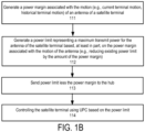
- Figure 1B is a flow diagram of one embodiment of another process for performing UPC for satellite terminal.
- the process is performed by processing logic that may comprise hardware (circuitry, dedicated logic, etc.), software (e.g., software running on a chip), firmware, or a combination of the three.
- operations of the process of Figure 1B are performed by a controller, including one or more processors, of the satellite terminal.
- operations of the process of Figure 1B are performed by a controller, including one or more processors, of the satellite terminal and/or a hub in a satellite communication system.
- the process begins by processing logic generating a power margin associated with the motion (or motion profile) of a satellite terminal antenna (processing block 111).
- the motion includes current terminal motion.
- the motion of the antenna includes historical terminal motion and current terminal motion. Note that when using both current terminal motion and historical terminal motion for generating a power margin for motion, the two may be combined through the use of weighting (e.g., Fourier transforms) so that current terminal motion is weighted more heavily than past historical terminal motion.
- weighting e.g., Fourier transforms
- processing logic After generating the power margin, processing logic generates a power limit representing a maximum transmit power for the antenna of the satellite terminal based, at least in part, on the power margin associated with motion of the antenna (processing block 112). In one embodiment, generating the power limit comprises reducing an existing power limit by an amount of the power margin for motion.
- processing logic After generating the power limit, processing logic sends the power limit less the power margin to the hub (processing block 113) and the transmit power of the satellite terminal is then controlled using UPC based on the power limit (processing block 114).
- the hub updates or sends another power limit to the satellite terminal to control the transmit power of the antenna of the satellite terminal using UPC.
- the motion profile that is used to generate a power margin for motion uses at least a sensor or sensors for orientation.
- sensors may determine a current orientation, a change in orientation, and/or a rate of change in orientation.
- sensors for velocity or acceleration could be used to obtain information to augment the orientation information.
- Other information used to create a motion profile may include whether the satellite terminal has a connection or not, the frequency at which the satellite terminal antenna is to operate, and other information (e.g.
- BUC Block Upconverter
- amplifier power range including BUC linear range, antenna gain, antenna gain based on orientation, temperature, antenna temperature performance, etc.
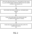
- Figure 2 is a flow diagram of one embodiment of a process for generating a motion profile of a satellite terminal antenna.
- the process is performed by processing logic that may comprise hardware (circuitry, dedicated logic, etc.), software (e.g., software running on a chip), firmware, or a combination of the three.
- operations of the process of Figure 2 are performed by a controller, including one or more processors, of the satellite terminal.
- operations of the process of Figure 2 are performed by a controller, including one or more processors, of the satellite terminal, a cloud-based server or other computer system, and/or a hub in a satellite communication system.
- the process begins by processing logic collecting motion data from an antenna (processing block 201).
- the motion data includes motion data from motion sensors on the antenna such as, for example, gyroscopes, accelerometers, etc.
- the motion data also includes longitude and latitude data where the term satellite terminal has a satellite connection or not, frequency at which the antenna is to be operated, and other motion data.
- processing logic sends the collected motion data to a remote system (processing block 202).
- a remote system In one embodiment, this is optional.
- the remote system is a cloud-based system for generating the motion profile based on the collective motion data.
- processing logic In response to the collected motion data, processing logic creates a motion profile (processing block 203). In one embodiment this is done on a satellite terminal itself using one or more processors of a controller. In another embodiment this is done, as described above, in a cloud-based system.
- a motion power margin is created for the satellite terminal antenna (processing block 204).
- the power margin may be used, as described above, in calculating the power limit for the satellite terminal antenna.
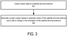
- Figure 3 illustrates an alternative embodiment for generating a power margin that may be used in setting a power limit for a satellite terminal antenna.
- the process is performed by processing logic that may comprise hardware (circuitry, dedicated logic, etc.), software (e.g., software running on a chip), firmware, or a combination of the three.
- operations of the process of Figure 1A are performed by a controller, including one or more processors, of the satellite terminal.
- operations of the process of Figure 3 are performed by a controller, including one or more processors, of the satellite terminal and/or a hub in a satellite communication system.
- processing logic collects the motion data with satellite terminal antenna (processing block 301). Using the collected motion data, processing logic generates a power margin based on absolute motion data of its satellite antenna and a rate of change in orientation of the satellite terminal antenna (processing block 302). In one embodiment, processing logic generates a power margin based on absolute motion data of its satellite antenna and a rate of change in orientation of the satellite terminal antenna by averaging (e.g., a rolling average for rate of change for some predetermined time), with the absolute motion data being the instantaneous motion from the sensors on the satellite terminal. From that information, and accounting for other historical motion data (e.g., data stored in memory 512 of Figure 5 ), processing logic can determine the power based margin. In another embodiment, if the absolute maximum degree per second (DPS) change is known, processing logic can determine how much hub margin needs to be held due to the time delay of the hub.
- DPS absolute maximum degree per second
- Figure 4 illustrates a flow diagram for a satellite terminal antenna generating a power limit.
- the process is performed by processing logic that may comprise hardware (circuitry, dedicated logic, etc.), software (e.g., software running on a chip), firmware, or a combination of the three.
- operations of the process of Figure 1A are performed by a controller, including one or more processors, of the satellite terminal.
- operations of the process of Figure 4 are performed by a controller, including one or more processors, of the satellite terminal.
- a pointing angle calculator 401 generates a scan angle 402 and a geoskew 403.
- the processing logic uses scan angle 402 and geographic skew angle (geoskew) 403 to access a power look-up table (LUT) 404.
- processing logic outputs power limit 405 from power limit LUT 404 based on scan angle 402 and geoskew 403.
- Power limit 405 is received by motion power margin calculator 406 along with motion data 407 from motion sensors 408 and historical motion data stored in storage 409. Based on power limit 405 and the motion data 407, motion power margin calculator 406 generates a power limit less the margin 410 and sends it to hub 411. That is, motion power margin calculator 406 takes the PSD limit and subtracts out the motion power margin to generate the power limit 405 less margin 410 and sends it to hub 411.
- the PSD is gathered from the ASM, and a power margin can be calculated from capturing the motion profile to generate a specific margin for that terminal. Then this PSD less the power margin is sent to the hub, and the hub side power margin may be set to 0 dB, essentially increasing efficiency by making each margin unique rather than one large coarse value.
- motion power margin calculator 406 generates the power margin for motion using rate of change and the absolute motion of the satellite terminal antenna. In one embodiment, this is performed as described above. In one embodiment, motion power margin calculator 406 examiners the PSD limit and determines the amount of change that can occur over the motion provide. In one embodiment, the power margin is set based on the amount of motion that may occur during the time the delay in waiting for the hub to respond with respect to the power limit less the power margin for motion that is provided from the terminal.
- the power limit less the power margin is set to 18 based on the amount of motion during the delay in waiting for the hub to respond with respect to the power limit less the power margin for motion.
- motion power margin calculator 406 determines the power margin and subtracts it from the power limit 405 to generate power limit less margin 410.
- motion power margin calculator 406 has two states: moving vs. not moving and generates a power margin for use when the satellite terminal antenna is moving.
- the motion upon which it bases the motion margin may be motion over a particular time period (e.g., motion over the past 5 minutes) or could be over a longer period of time (e.g., a terminal's motion over several days (e.g., 10 days).
- motion power margin calculator 406 may cull outliers and determine the maximum expected motion over the time period used.
- motion power margin calculator 406 uses machine learning and artificial intelligence to determine a motion profile and/or a power margin for motion. Such information may include other forms of information, including current position, temperature, time of year, etc.
- Figure 5 illustrates one embodiment of a satellite terminal that includes an antenna subsystem module (ASM) 501 coupled to a modem 504.
- ASM antenna subsystem module
- modem 504 is part of ASM 501.
- ASM 501 includes an antenna aperture 502 and controller 503.
- Antenna aperture 503 may include, for example, but not limited to, an antenna aperture described herein.
- controller 503 comprises one or more processors for performing operations for the satellite terminal.
- controller 503 includes a motion power margin calculator 510 and a pointing angle calculator 511, such as, for example, those described in Figure 4 .
- the terminal also includes one or more motion sensors, such as, for example, motion sensor 408 shown in Figure 4 , for providing current motion information and a memory 512 for storing and providing historical motion data, such as, for example, historical data storage 409 shown in Figure 4 .
- memory 512 includes a power limit LUT such as, for example, power limit LUT 404 shown in Figure 4 .
- controller 503 generates a new power margin using motion power margin calculator 510 and sends it to a hub at regular intervals (e.g., every day) via antenna aperture 502.
- the power margin is maintained in the terminal and the controller generates a UPC power limit using the power margin.
- the terminal of Figure 5 is in communication with the hub and/or another remote system (e.g., a cloud-based server or computer system) for sending updated algorithms to the terminal for generating the power margin for motion.
- another remote system e.g., a cloud-based server or computer system
- One advantage is the ability to require less margin on terminal uplink, thus allowing for more transmit power, which leads to more bits per hertz.
- this advantage is proportional to the amount of change in uplink power limit relative to antenna orientation. For example, an elliptical parabolic antenna will have some improvement, but a flat panel, electronically scanned antenna (ESA), will have more benefit.
- ESA electronically scanned antenna
- the techniques described above may be used with flat panel antennas. Embodiments of such flat panel antennas are disclosed.
- the flat panel antennas include one or more arrays of antenna elements on an antenna aperture.
- the antenna elements comprise liquid crystal cells.
- the flat panel antenna is a cylindrically fed antenna that includes matrix drive circuitry to uniquely address and drive each of the antenna elements that are not placed in rows and columns. In one embodiment, the elements are placed in rings.
- the antenna aperture having the one or more arrays of antenna elements is comprised of multiple segments coupled together. When coupled together, the combination of the segments form closed concentric rings of antenna elements. In one embodiment, the concentric rings are concentric with respect to the antenna feed.
- the flat panel antenna is part of a metamaterial antenna system.
- a metamaterial antenna system for communications satellite earth stations are described.
- the antenna system is a component or subsystem of a satellite earth station (ES) operating on a mobile platform (e.g., aeronautical, maritime, land, etc.) that operates using either Ka-band frequencies or Ku-band frequencies for civil commercial satellite communications.
- ES satellite earth station
- mobile platform e.g., aeronautical, maritime, land, etc.
- embodiments of the antenna system also can be used in earth stations that are not on mobile platforms (e.g., fixed or transportable earth stations).
- the antenna system uses surface scattering metamaterial technology to form and steer transmit and receive beams through separate antennas.
- the antenna systems are analog systems, in contrast to antenna systems that employ digital signal processing to electrically form and steer beams (such as phased array antennas).
- the antenna system is comprised of three functional subsystems: (1) a wave guiding structure consisting of a cylindrical wave feed architecture; (2) an array of wave scattering metamaterial unit cells that are part of antenna elements; and (3) a control structure to command formation of an adjustable radiation field (beam) from the metamaterial scattering elements using holographic principles.
- a wave guiding structure consisting of a cylindrical wave feed architecture
- an array of wave scattering metamaterial unit cells that are part of antenna elements
- a control structure to command formation of an adjustable radiation field (beam) from the metamaterial scattering elements using holographic principles.
- FIG. 6 illustrates the schematic of one embodiment of a cylindrically fed holographic radial aperture antenna.
- the antenna aperture has one or more arrays 601 of antenna elements 603 that are placed in concentric rings around an input feed 602 of the cylindrically fed antenna.
- antenna elements 603 are radio frequency (RF) resonators that radiate RF energy.
- antenna elements 603 comprise both Rx and Tx irises that are interleaved and distributed on the whole surface of the antenna aperture. Examples of such antenna elements are described in greater detail below. Note that the RF resonators described herein may be used in antennas that do not include a cylindrical feed.
- the antenna includes a coaxial feed that is used to provide a cylindrical wave feed via input feed 602.
- the cylindrical wave feed architecture feeds the antenna from a central point with an excitation that spreads outward in a cylindrical manner from the feed point. That is, a cylindrically fed antenna creates an outward travelling concentric feed wave. Even so, the shape of the cylindrical feed antenna around the cylindrical feed can be circular, square or any shape. In another embodiment, a cylindrically fed antenna creates an inward travelling feed wave. In such a case, the feed wave most naturally comes from a circular structure.
- antenna elements 603 comprise irises and the aperture antenna of Figure 6 is used to generate a main beam shaped by using excitation from a cylindrical feed wave for radiating irises through tunable liquid crystal (LC) material.
- the antenna can be excited to radiate a horizontally or vertically polarized electric field at desired scan angles.
- the antenna elements comprise a group of patch antennas.
- This group of patch antennas comprises an array of scattering metamaterial elements.
- each scattering element in the antenna system is part of a unit cell that consists of a lower conductor, a dielectric substrate and an upper conductor that embeds a complementary electric inductive-capacitive resonator ("complementary electric LC" or "CELC”) that is etched in or deposited onto the upper conductor.
- CELC complementary electric inductive-capacitive resonator
- LC in the context of CELC refers to inductance-capacitance, as opposed to liquid crystal.
- a liquid crystal is disposed in the gap around the scattering element. This LC is driven by the direct drive embodiments described above.
- liquid crystal is encapsulated in each unit cell and separates the lower conductor associated with a slot from an upper conductor associated with its patch.
- Liquid crystal has a permittivity that is a function of the orientation of the molecules comprising the liquid crystal, and the orientation of the molecules (and thus the permittivity) can be controlled by adjusting the bias voltage across the liquid crystal.
- the liquid crystal integrates an on/off switch for the transmission of energy from the guided wave to the CELC. When switched on, the CELC emits an electromagnetic wave like an electrically small dipole antenna. Note that the teachings herein are not limited to having a liquid crystal that operates in a binary fashion with respect to energy transmission.
- the feed geometry of this antenna system allows the antenna elements to be positioned at forty-five-degree (45°) angles to the vector of the wave in the wave feed. Note that other positions may be used (e.g., at 40° angles). This position of the elements enables control of the free space wave received by or transmitted/radiated from the elements.
- the antenna elements are arranged with an inter-element spacing that is less than a free-space wavelength of the operating frequency of the antenna. For example, if there are four scattering elements per wavelength, the elements in the 30 GHz transmit antenna will be approximately 2.5 mm (i.e., 1/4th the 10mm free-space wavelength of 30 GHz).
- the two sets of elements are perpendicular to each other and simultaneously have equal amplitude excitation if controlled to the same tuning state. Rotating them +/-45 degrees relative to the feed wave excitation achieves both desired features at once. Rotating one set 0 degrees and the other 90 degrees would achieve the perpendicular goal, but not the equal amplitude excitation goal. Note that 0 and 90 degrees may be used to achieve isolation when feeding the array of antenna elements in a single structure from two sides.
- the amount of radiated power from each unit cell is controlled by applying a voltage to the patch (potential across the LC channel) using a controller. Traces to each patch are used to provide the voltage to the patch antenna. The voltage is used to tune or detune the capacitance and thus the resonance frequency of individual elements to effectuate beam forming. The voltage required is dependent on the liquid crystal mixture being used.
- the voltage tuning characteristic of liquid crystal mixtures is mainly described by a threshold voltage at which the liquid crystal starts to be affected by the voltage and the saturation voltage, above which an increase of the voltage does not cause major tuning in liquid crystal. These two characteristic parameters can change for different liquid crystal mixtures.
- a matrix drive is used to apply voltage to the patches in order to drive each cell separately from all the other cells without having a separate connection for each cell (direct drive). Because of the high density of elements, the matrix drive is an efficient way to address each cell individually.
- the control structure for the antenna system has 2 main components: the antenna array controller, which includes drive electronics, for the antenna system, is below the wave scattering structure, while the matrix drive switching array is interspersed throughout the radiating RF array in such a way as to not interfere with the radiation.
- the drive electronics for the antenna system comprise commercial off-the shelf LCD controls used in commercial television appliances that adjust the bias voltage for each scattering element by adjusting the amplitude or duty cycle of an AC bias signal to that element.
- the antenna array controller also contains a microprocessor executing the software.
- the control structure may also incorporate sensors (e.g., a GPS receiver, a three-axis compass, a 3-axis accelerometer, 3-axis gyro, 3-axis magnetometer, etc.) to provide location and orientation information to the processor.
- sensors e.g., a GPS receiver, a three-axis compass, a 3-axis accelerometer, 3-axis gyro, 3-axis magnetometer, etc.
- the location and orientation information may be provided to the processor by other systems in the earth station and/or may not be part of the antenna system.
- the antenna array controller controls which elements are turned off and those elements turned on and at which phase and amplitude level at the frequency of operation.
- the elements are selectively detuned for frequency operation by voltage application.
- a controller supplies an array of voltage signals to the RF patches to create a modulation, or control pattern.
- the control pattern causes the elements to be turned to different states.
- multistate control is used in which various elements are turned on and off to varying levels, further approximating a sinusoidal control pattern, as opposed to a square wave (i.e., a sinusoid gray shade modulation pattern).
- some elements radiate more strongly than others, rather than some elements radiate and some do not.
- Variable radiation is achieved by applying specific voltage levels, which adjusts the liquid crystal permittivity to varying amounts, thereby detuning elements variably and causing some elements to radiate more than others.
- the generation of a focused beam by the metamaterial array of elements can be explained by the phenomenon of constructive and destructive interference.
- Individual electromagnetic waves sum up (constructive interference) if they have the same phase when they meet in free space and waves cancel each other (destructive interference) if they are in opposite phase when they meet in free space.
- the slots in a slotted antenna are positioned so that each successive slot is positioned at a different distance from the excitation point of the guided wave, the scattered wave from that element will have a different phase than the scattered wave of the previous slot. If the slots are spaced one quarter of a guided wavelength apart, each slot will scatter a wave with a one fourth phase delay from the previous slot.
- the number of patterns of constructive and destructive interference that can be produced can be increased so that beams can be pointed theoretically in any direction plus or minus ninety degrees (90°) from the bore sight of the antenna array, using the principles of holography.
- the antenna can change the direction of the main beam.
- the time required to turn the unit cells on and off dictates the speed at which the beam can be switched from one location to another location.
- the antenna system produces one steerable beam for the uplink antenna and one steerable beam for the downlink antenna.
- the antenna system uses metamaterial technology to receive beams and to decode signals from the satellite and to form transmit beams that are directed toward the satellite.
- the antenna systems are analog systems, in contrast to antenna systems that employ digital signal processing to electrically form and steer beams (such as phased array antennas).
- the antenna system is considered a "surface" antenna that is planar and relatively low profile, especially when compared to conventional satellite dish receivers.
- Figure 7 illustrates a perspective view of one row of antenna elements that includes a ground plane and a reconfigurable resonator layer.
- Reconfigurable resonator layer 1230 includes an array of tunable slots 1210.
- the array of tunable slots 1210 can be configured to point the antenna in a desired direction.
- Each of the tunable slots can be tuned/adjusted by varying a voltage across the liquid crystal.
- Control module 1280 is coupled to reconfigurable resonator layer 1230 to modulate the array of tunable slots 1210 by varying the voltage across the liquid crystal in Figure 8A .
- Control module 1280 may include a Field Programmable Gate Array ("FPGA"), a microprocessor, a controller, System-on-a-Chip (SoC), or other processing logic.
- control module 1280 includes logic circuitry (e.g., multiplexer) to drive the array of tunable slots 1210.
- control module 1280 receives data that includes specifications for a holographic diffraction pattern to be driven onto the array of tunable slots 1210.
- the holographic diffraction patterns may be generated in response to a spatial relationship between the antenna and a satellite so that the holographic diffraction pattern steers the downlink beams (and uplink beam if the antenna system performs transmit) in the appropriate direction for communication.
- a control module similar to control module 1280 may drive each array of tunable slots described in the figures of the disclosure.
- Radio Frequency (“RF”) holography is also possible using analogous techniques where a desired RF beam can be generated when an RF reference beam encounters an RF holographic diffraction pattern.
- the reference beam is in the form of a feed wave, such as feed wave 1205 (approximately 20 GHz in some embodiments).
- feed wave 1205 approximately 20 GHz in some embodiments.
- an interference pattern is calculated between the desired RF beam (the object beam) and the feed wave (the reference beam).
- the interference pattern is driven onto the array of tunable slots 1210 as a diffraction pattern so that the feed wave is "steered” into the desired RF beam (having the desired shape and direction).
- the feed wave encountering the holographic diffraction pattern "reconstructs" the object beam, which is formed according to design requirements of the communication system.
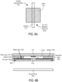
- FIG 8A illustrates one embodiment of a tunable resonator/slot 1210.
- Tunable slot 1210 includes an iris/slot 1212, a radiating patch 1211, and liquid crystal 1213 disposed between iris 1212 and patch 1211.
- radiating patch 1211 is co-located with iris 1212.
- Figure 8B illustrates a cross section view of one embodiment of a physical antenna aperture.
- the antenna aperture includes ground plane 1245, and a metal layer 1236 within iris layer 1233, which is included in reconfigurable resonator layer 1230.
- the antenna aperture of Figure 8B includes a plurality of tunable resonator/slots 1210 of Figure 8A .
- Iris/slot 1212 is defined by openings in metal layer 1236.
- a feed wave such as feed wave 1205 of Figure 7 , may have a microwave frequency compatible with satellite communication channels. The feed wave propagates between ground plane 1245 and resonator layer 1230.
- Reconfigurable resonator layer 1230 also includes gasket layer 1232 and patch layer 1231.
- Gasket layer 1232 is disposed between patch layer 1231 and iris layer 1233.
- a spacer could replace gasket layer 1232.
- iris layer 1233 is a printed circuit board ("PCB") that includes a copper layer as metal layer 1236.
- iris layer 1233 is glass. Iris layer 1233 may be other types of substrates.
- Openings may be etched in the copper layer to form slots 1212.
- iris layer 1233 is conductively coupled by a conductive bonding layer to another structure (e.g., a waveguide) in Figure 8B . Note that in an embodiment the iris layer is not conductively coupled by a conductive bonding layer and is instead interfaced with a non-conducting bonding layer.
- Patch layer 1231 may also be a PCB that includes metal as radiating patches 1211.
- gasket layer 1232 includes spacers 1239 that provide a mechanical standoff to define the dimension between metal layer 1236 and patch 1211.
- the spacers are 75 microns, but other sizes may be used (e.g., 3-200 mm).
- the antenna aperture of Figure 8B includes multiple tunable resonator/slots, such as tunable resonator/slot 1210 includes patch 1211, liquid crystal 1213, and iris 1212 of Figure 8A .
- the chamber for liquid crystal 1213 is defined by spacers 1239, iris layer 1233 and metal layer 1236. When the chamber is filled with liquid crystal, patch layer 1231 can be laminated onto spacers 1239 to seal liquid crystal within resonator layer 1230.
- the resonant frequency of slot 1210 affects the energy radiated from feed wave 1205 propagating through the waveguide.
- the resonant frequency of a slot 1210 may be adjusted (by varying the capacitance) to 17 GHz so that the slot 1210 couples substantially no energy from feed wave 1205.
- the resonant frequency of a slot 1210 may be adjusted to 20 GHz so that the slot 1210 couples energy from feed wave 1205 and radiates that energy into free space.
- the examples given are binary (fully radiating or not radiating at all), full gray scale control of the reactance, and therefore the resonant frequency of slot 1210 is possible with voltage variance over a multi-valued range.
- the energy radiated from each slot 1210 can be finely controlled so that detailed holographic diffraction patterns can be formed by the array of tunable slots.
- tunable slots in a row are spaced from each other by ⁇ /5. Other spacings may be used. In one embodiment, each tunable slot in a row is spaced from the closest tunable slot in an adjacent row by ⁇ /2, and, thus, commonly oriented tunable slots in different rows are spaced by ⁇ /4, though other spacings are possible (e.g., ⁇ /5, ⁇ /6.3). In another embodiment, each tunable slot in a row is spaced from the closest tunable slot in an adjacent row by ⁇ /3.
- Embodiments use reconfigurable metamaterial technology, such as described in U.S. Patent Application No. 14/550,178, entitled “Dynamic Polarization and Coupling Control from a Steerable Cylindrically Fed Holographic Antenna", filed November 21, 2014 and U.S. Patent Application No. 14/610,502, entitled “Ridged Waveguide Feed Structures for Reconfigurable Antenna”, filed January 30, 2015 .
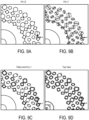
- FIGs 9A-D illustrate one embodiment of the different layers for creating the slotted array.
- the antenna array includes antenna elements that are positioned in rings, such as the example rings shown in Figure 1A . Note that in this example the antenna array has two different types of antenna elements that are used for two different types of frequency bands.
- Figure 9A illustrates a portion of the first iris board layer with locations corresponding to the slots.
- the circles are open areas/slots in the metallization in the bottom side of the iris substrate, and are for controlling the coupling of elements to the feed (the feed wave). Note that this layer is an optional layer and is not used in all designs.
- Figure 9B illustrates a portion of the second iris board layer containing slots.
- Figure 9C illustrates patches over a portion of the second iris board layer.
- Figure 9D illustrates a top view of a portion of the slotted array.
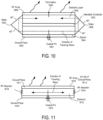
- Figure 10 illustrates a side view of one embodiment of a cylindrically fed antenna structure.
- the antenna produces an inwardly travelling wave using a double layer feed structure (i.e., two layers of a feed structure).
- the antenna includes a circular outer shape, though this is not required. That is, non-circular inward travelling structures can be used.
- the antenna structure in Figure 10 includes a coaxial feed, such as, for example, described in U.S. Publication No. 2015/0236412, entitled “Dynamic Polarization and Coupling Control from a Steerable Cylindrically Fed Holographic Antenna", filed on November 21, 2014 .
- a coaxial pin 1601 is used to excite the field on the lower level of the antenna.
- coaxial pin 1601 is a 50 ⁇ coax pin that is readily available.
- Coaxial pin 1601 is coupled (e.g., bolted) to the bottom of the antenna structure, which is conducting ground plane 1602.
- interstitial conductor 1603 Separate from conducting ground plane 1602 is interstitial conductor 1603, which is an internal conductor.
- conducting ground plane 1602 and interstitial conductor 1603 are parallel to each other.
- the distance between ground plane 1602 and interstitial conductor 1603 is 0.1 - 0.15". In another embodiment, this distance may be ⁇ /2, where ⁇ is the wavelength of the travelling wave at the frequency of operation.
- Ground plane 1602 is separated from interstitial conductor 1603 via a spacer 1604.
- spacer 1604 is a foam or air-like spacer.
- spacer 1604 comprises a plastic spacer.
- dielectric layer 1605 is plastic.
- the purpose of dielectric layer 1605 is to slow the travelling wave relative to free space velocity. In one embodiment, dielectric layer 1605 slows the travelling wave by 30% relative to free space.
- the range of indices of refraction that are suitable for beam forming are 1.2 - 1.8, where free space has by definition an index of refraction equal to 1.
- Other dielectric spacer materials such as, for example, plastic, may be used to achieve this effect. Note that materials other than plastic may be used as long as they achieve the desired wave slowing effect.
- a material with distributed structures may be used as dielectric 1605, such as periodic sub-wavelength metallic structures that can be machined or lithographically defined, for example.
- An RF-array 1606 is on top of dielectric 1605.
- the distance between interstitial conductor 1603 and RF-array 1606 is 0.1 - 0.15". In another embodiment, this distance may be ⁇ eff /2, where ⁇ eff is the effective wavelength in the medium at the design frequency.
- the antenna includes sides 1607 and 1608.
- Sides 1607 and 1608 are angled to cause a travelling wave feed from coax pin 1601 to be propagated from the area below interstitial conductor 1603 (the spacer layer) to the area above interstitial conductor 1603 (the dielectric layer) via reflection.
- the angle of sides 1607 and 1608 are at 45° angles.
- sides 1607 and 1608 could be replaced with a continuous radius to achieve the reflection. While Figure 10 shows angled sides that have angle of 45 degrees, other angles that accomplish signal transmission from lower level feed to upper level feed may be used.
- the 45° angles are replaced with a single step.
- the steps on one end of the antenna go around the dielectric layer, interstitial the conductor, and the spacer layer. The same two steps are at the other ends of these layers.
- a termination 1609 is included in the antenna at the geometric center of the antenna.
- termination 1609 comprises a pin termination (e.g., a 50 ⁇ pin).
- termination 1609 comprises an RF absorber that terminates unused energy to prevent reflections of that unused energy back through the feed structure of the antenna. These could be used at the top of RF array 1606.
- FIG 11 illustrates another embodiment of the antenna system with an outgoing wave.
- two ground planes 1610 and 1611 are substantially parallel to each other with a dielectric layer 1612 (e.g., a plastic layer, etc.) in between ground planes.
- RF absorbers 1619 e.g., resistors
- a coaxial pin 1615 e.g., 50 ⁇
- An RF array 1616 is on top of dielectric layer 1612 and ground plane 1611.
- a feed wave is fed through coaxial pin 1615 and travels concentrically outward and interacts with the elements of RF array 1616.
- the cylindrical feed in both the antennas of Figures 10 and 11 improves the service angle of the antenna.
- the antenna system has a service angle of seventy-five degrees (75°) from the bore sight in all directions.
- the overall antenna gain is dependent on the gain of the constituent elements, which themselves are angle-dependent.
- the overall antenna gain typically decreases as the beam is pointed further off bore sight. At 75 degrees off bore sight, significant gain degradation of about 6 dB is expected.
- Embodiments of the antenna having a cylindrical feed solve one or more problems. These include dramatically simplifying the feed structure compared to antennas fed with a corporate divider network and therefore reducing total required antenna and antenna feed volume; decreasing sensitivity to manufacturing and control errors by maintaining high beam performance with coarser controls (extending all the way to simple binary control); giving a more advantageous side lobe pattern compared to rectilinear feeds because the cylindrically oriented feed waves result in spatially diverse side lobes in the far field; and allowing polarization to be dynamic, including allowing left-hand circular, right-hand circular, and linear polarizations, while not requiring a polarizer.
- RF array 1606 of Figure 10 and RF array 1616 of Figure 11 include a wave scattering subsystem that includes a group of patch antennas (i.e., scatterers) that act as radiators.
- This group of patch antennas comprises an array of scattering metamaterial elements.
- each scattering element in the antenna system is part of a unit cell that consists of a lower conductor, a dielectric substrate and an upper conductor that embeds a complementary electric inductive-capacitive resonator ("complementary electric LC" or “CELC”) that is etched in or deposited onto the upper conductor.
- a complementary electric inductive-capacitive resonator (“complementary electric LC” or “CELC”) that is etched in or deposited onto the upper conductor.
- a liquid crystal is injected in the gap around the scattering element.
- Liquid crystal is encapsulated in each unit cell and separates the lower conductor associated with a slot from an upper conductor associated with its patch.
- Liquid crystal has a permittivity that is a function of the orientation of the molecules comprising the liquid crystal, and the orientation of the molecules (and thus the permittivity) can be controlled by adjusting the bias voltage across the liquid crystal. Using this property, the liquid crystal acts as an on/off switch for the transmission of energy from the guided wave to the CELC. When switched on, the CELC emits an electromagnetic wave like an electrically small dipole antenna.
- Controlling the thickness of the LC increases the beam switching speed.
- a fifty percent (50%) reduction in the gap between the lower and the upper conductor results in a fourfold increase in speed.
- the thickness of the liquid crystal results in a beam switching speed of approximately fourteen milliseconds (14ms).
- the LC is doped in a manner well-known in the art to improve responsiveness so that a seven millisecond (7ms) requirement can be met.
- the CELC element is responsive to a magnetic field that is applied parallel to the plane of the CELC element and perpendicular to the CELC gap complement.
- a voltage is applied to the liquid crystal in the metamaterial scattering unit cell, the magnetic field component of the guided wave induces a magnetic excitation of the CELC, which, in turn, produces an electromagnetic wave in the same frequency as the guided wave.
- the phase of the electromagnetic wave generated by a single CELC can be selected by the position of the CELC on the vector of the guided wave.
- Each cell generates a wave in phase with the guided wave parallel to the CELC. Because the CELCs are smaller than the wave length, the output wave has the same phase as the phase of the guided wave as it passes beneath the CELC.
- the cylindrical feed geometry of this antenna system allows the CELC elements to be positioned at forty-five-degree (45°) angles to the vector of the wave in the wave feed. This position of the elements enables control of the polarization of the free space wave generated from or received by the elements.
- the CELCs are arranged with an inter-element spacing that is less than a free-space wavelength of the operating frequency of the antenna. For example, if there are four scattering elements per wavelength, the elements in the 30 GHz transmit antenna will be approximately 2.5 mm (i.e., 1/4th the 10mm free-space wavelength of 30 GHz).
- the CELCs are implemented with patch antennas that include a patch co-located over a slot with liquid crystal between the two.
- the metamaterial antenna acts like a slotted (scattering) wave guide. With a slotted wave guide, the phase of the output wave depends on the location of the slot in relation to the guided wave.
- the cells are placed on concentric rings and each of the cells is connected to a transistor that is placed beside the cell and acts as a switch to drive each cell separately.
- the matrix drive circuitry is built in order to connect every transistor with a unique address as the matrix drive approach requires. Because the matrix drive circuit is built by row and column traces (similar to LCDs) but the cells are placed on rings, there is no systematic way to assign a unique address to each transistor. This mapping problem results in very complex circuitry to cover all the transistors and leads to a significant increase in the number of physical traces to accomplish the routing. Because of the high density of cells, those traces disturb the RF performance of the antenna due to coupling effect. Also, due to the complexity of traces and high packing density, the routing of the traces cannot be accomplished by commercially available layout tools.
- the matrix drive circuitry is predefined before the cells and transistors are placed. This ensures a minimum number of traces that are necessary to drive all the cells, each with a unique address. This strategy reduces the complexity of the drive circuitry and simplifies the routing, which subsequently improves the RF performance of the antenna.
- the cells are placed on a regular rectangular grid composed of rows and columns that describe the unique address of each cell.
- the cells are grouped and transformed to concentric circles while maintaining their address and connection to the rows and columns as defined in the first step.
- a goal of this transformation is not only to put the cells on rings but also to keep the distance between cells and the distance between rings constant over the entire aperture. In order to accomplish this goal, there are several ways to group the cells.
- a TFT package is used to enable placement and unique addressing in the matrix drive.
- Figure 13 illustrates one embodiment of a TFT package. Referring to Figure 13 , a TFT and a hold capacitor 1803 is shown with input and output ports. There are two input ports connected to traces 1801 and two output ports connected to traces 1802 to connect the TFTs together using the rows and columns.
- the row and column traces cross in 90° angles to reduce, and potentially minimize, the coupling between the row and column traces.
- the row and column traces are on different layers.
- FIG. 14 is a block diagram of another embodiment of a communication system having simultaneous transmit and receive paths. While only one transmit path and one receive path are shown, the communication system may include more than one transmit path and/or more than one receive path.
- antenna 1401 includes two spatially interleaved antenna arrays operable independently to transmit and receive simultaneously at different frequencies as described above.
- antenna 1401 is coupled to diplexer 1445.
- the coupling may be by one or more feeding networks.
- diplexer 1445 combines the two signals and the connection between antenna 1401 and diplexer 1445 is a single broad-band feeding network that can carry both frequencies.
- Diplexer 1445 is coupled to a low noise block down converter (LNBs) 1427, which performs a noise filtering function and a down conversion and amplification function in a manner well-known in the art.
- LNB 1427 is in an out-door unit (ODU).
- ODU out-door unit
- LNB 1427 is integrated into the antenna apparatus.
- LNB 1427 is coupled to a modem 1460, which is coupled to computing system 1440 (e.g., a computer system, modem, etc.).
- Modem 1460 includes an analog-to-digital converter (ADC) 1422, which is coupled to LNB 1427, to convert the received signal output from diplexer 1445 into digital format. Once converted to digital format, the signal is demodulated by demodulator 1423 and decoded by decoder 1424 to obtain the encoded data on the received wave. The decoded data is then sent to controller 1425, which sends it to computing system 1440.
- ADC analog-to-digital converter
- Modem 1460 also includes an encoder 1430 that encodes data to be transmitted from computing system 1440.
- the encoded data is modulated by modulator 1431 and then converted to analog by digital-to-analog converter (DAC) 1432.
- DAC digital-to-analog converter
- the analog signal is then filtered by a BUC (up-convert and high pass amplifier) 1433 and provided to one port of diplexer 1445.
- BUC 1433 is in an out-door unit (ODU).
- Diplexer 1445 operating in a manner well-known in the art provides the transmit signal to antenna 1401 for transmission.
- Controller 1450 controls antenna 1401, including the two arrays of antenna elements on the single combined physical aperture.
- the communication system would be modified to include the combiner/arbiter described above. In such a case, the combiner/arbiter after the modem but before the BUC and LNB.
- the full duplex communication system shown in Figure 14 has a number of applications, including but not limited to, internet communication, vehicle communication (including software updating), etc.
- the present invention also relates to apparatus for performing the operations herein.
- This apparatus may be specially constructed for the required purposes, or it may comprise a general-purpose computer selectively activated or reconfigured by a computer program stored in the computer.
- a computer program may be stored in a computer readable storage medium, such as, but is not limited to, any type of disk including floppy disks, optical disks, CD-ROMs, and magnetic-optical disks, read-only memories (ROMs), random access memories (RAMs), EPROMs, EEPROMs, magnetic or optical cards, or any type of media suitable for storing electronic instructions, and each coupled to a computer system bus.
- a machine-readable medium includes any mechanism for storing or transmitting information in a form readable by a machine (e.g., a computer).
- a machine-readable medium includes read only memory ("ROM”); random access memory (“RAM”); magnetic disk storage media; optical storage media; flash memory devices; etc.
Landscapes
- Engineering & Computer Science (AREA)
- Physics & Mathematics (AREA)
- General Physics & Mathematics (AREA)
- Astronomy & Astrophysics (AREA)
- Signal Processing (AREA)
- Aviation & Aerospace Engineering (AREA)
- Computer Networks & Wireless Communication (AREA)
- Remote Sensing (AREA)
- Electromagnetism (AREA)
- Radio Relay Systems (AREA)
- Variable-Direction Aerials And Aerial Arrays (AREA)
- Mobile Radio Communication Systems (AREA)
- Stereo-Broadcasting Methods (AREA)
Description
- Embodiments of the present invention relate to wireless communication; more particularly, embodiments of the present invention relate to uplink power control for satellite antennas that is based on power spectral density (PSD).
- In the world of GEO satellite communications, the equatorial plane some 36,000 km away from the surface of the earth is typically populated every 2 degrees in longitude with a satellite. The satellite industry shares the frequency spectrum. This places a burden on the satellite communications user segment (antennas) to produce pencil-beam emissions. These pencil beams focus as much of its energy as possible on its target satellite, while protecting neighboring satellites from unwanted and/or harmful interference through spatial isolation.
- It would be difficult to design an antenna that radiates zero energy towards neighboring satellites. This is widely recognized in the satellite industry, and some energy is expected to radiate towards unwanted satellite(s). However, it is critical to control the energy levels in these instances below acceptable thresholds. Satellite operators in coordination with ITU, FCC and other regulatory bodies have produced rules for maximum permissible power levels as a function of off-axis angles (away from target satellite). These rules are known as Power Spectral Density (PSD) masks, and they slightly vary depending on geographical region and satellite orbit slot nature. As such, most commonly enforced PSD masks are:
- FCC PSD Mask
- ITU PSD Mask
- Coordinated PSD Mask
- To stay compliant with regulatory PSD masks, an antenna/terminal operator has two choices: expand bandwidth of the channel in use when non-compliance is detected or lower the power output of the terminal when non-compliance is detected. In certain commercial satellite communication network configurations, bandwidth of the transmit (Tx) channels is fixed and cannot be changed dynamically, leaving power back-off as the only option.
EP 2 073 399 A2 describes a method and an apparatus for dynamically optimizing the transmission level of each remote terminal in a satellite-based communication network.US 2015/215029 A1 describes a hub terminal and remote client communicate via a target satellite in an inclined geosynchronous orbit. - The present invention is defined by the independent claims. Advantageous embodiments are described in the dependent claims, the following description and the drawings. Inter alia, techniques for motion mitigation for uplink power control are disclosed. In one embodiment, a method implemented at a satellite terminal for use in a satellite communication system comprises:
- generating a power margin associated with motion of an antenna of a satellite terminal; and
- generating a first power limit representing a maximum transmit power for the antenna based, at least in part, on the power margin.
- The described embodiments and the advantages thereof may best be understood by reference to the following description taken in conjunction with the accompanying drawings. These drawings in no way limit any changes in form and detail that may be made to the described embodiments by one skilled in the art without departing from the scope of the described embodiments.
-
Figure 1A is a flow diagram of one embodiment of a process for performing uplink power control (UPC). -
Figure 1B is a flow diagram of one embodiment of another process for performing UPC for satellite terminal. -
Figure 2 is a flow diagram of one embodiment of a process for generating a motion profile of a satellite terminal antenna. -
Figure 3 illustrates an alternative embodiment for generating a power margin that may be used in setting a power limit for a satellite terminal antenna. -
Figure 4 illustrates a flow diagram of one embodiment of a process for generating a power limit for a satellite terminal antenna. -
Figure 5 illustrates one embodiment of a satellite terminal that includes an antenna subsystem module (ASM). -
Figure 6 illustrates an aperture having one or more arrays of antenna elements placed in concentric rings around an input feed of the cylindrically fed antenna. -
Figure 7 illustrates a perspective view of one row of antenna elements that includes a ground plane and a reconfigurable resonator layer. -
Figure 8A illustrates one embodiment of a tunable resonator/slot. -
Figure 8B illustrates a cross section view of one embodiment of a physical antenna aperture. -
Figures 9A-D illustrate one embodiment of the different layers for creating the slotted array. -
Figure 10 illustrates a side view of one embodiment of a cylindrically fed antenna structure. -
Figure 11 illustrates another embodiment of the antenna system with an outgoing wave. -
Figure 12 illustrates one embodiment of the placement of matrix drive circuitry with respect to antenna elements. -
Figure 13 illustrates one embodiment of a TFT package. -
Figure 14 is a block diagram of another embodiment of a communication system having simultaneous transmit and receive paths. - A method and apparatus for performing uplink power control (UPC) for a satellite terminal antenna in a satellite communication system are disclosed. In one embodiment, the satellite antenna is a flat-panel antenna that electronically steers a beam using antenna elements. Examples of such antennas are described in more detail below. The techniques disclosed herein improve satellite terminal uplink throughput and efficiency and are not limited for use to the antennas described herein. In the following description, numerous details are set forth to provide a more thorough explanation of the present invention. It will be apparent, however, to one skilled in the art, that the present invention may be practiced without these specific details. In other instances, well-known structures and devices are shown in block diagram form, rather than in detail, in order to avoid obscuring the present invention.
- In one embodiment, the improvement in terminal uplink throughput and efficiency is achieved by adaptively changing the uplink power margin for UPC to take into account for motion of the satellite terminal antenna. The motion of different satellite terminal antennas may be due to different implementations of those antennas. For example, a satellite terminal attached to a moving vehicle such as car or a boat. The car and boat has different motions and are in different environments, thereby resulting in those antennas having different motion profiles. In one embodiment, the power margin associated with the motion of the antenna is based on the motion profile of the antenna. In one embodiment, the motion profile, and thus the corresponding motion margin, is based on the current terminal motion. In another embodiment, the motion profile, and thus the corresponding motion margin, is based on current and historical terminal motion. In the aggregate, this leads to less power margin needed for motion, which means more power can be used to transmit, thereby leading to an overall higher throughput and efficiency. For example, in one embodiment, at the beginning of operation (i.e., a first time), the power margin for motion starts as a large margin (e.g., ~2 dB) where there is no history data, but as motion data is collected over time there may be a reduction in motion margin (to <2 dB) if the terminal is not operating under what is considered maximum motion that would warrant having the initial power margin for motion used.
- In one embodiment, management of uplink power margin for motion is handled by the terminal, instead of the hub. In one embodiment, this results in up to 2dB more of uplink power. In one embodiment, this is done in a dynamic and scalable way, with no need to update PSD tables. That is, in one embodiment, the UPC is performed using the PSD limit. The PSD of an antenna is defined as the Equivalent Isotropic Radiated Power (EIRP) divided by the ratio of bandwidth of the transmitted signal versus a designated bandwidth per the regulatory body. Different space regulations (e.g., FCC, ITU, etc.) have different standards and maximum allowances for PSD. For example, the FCC, which regulates the space and frequency over the United States, has a density requirement of dBW/4 kHz bandwidth, whereas the ITU has a density requirement in units of dBW/40khz and governs most of the rest of the world. Therefore, for different locations on the Earth, in one embodiment, the terminal is aware of the region in which it is located, and with that, what requirements it must follow. It is also not uncommon for a satellite operator to set its own PSD limits for a satellite that may be stricter than the limit set by the ruling space regulation committee. In one embodiment, a goal is to be as close to the PSD limit as possible while holding enough margin to be confident that the PSD will not exceed pre-calculated limits, and the closer the PSD is to the limit, more modulation and coding schemes may be used which allow for a larger data rate to be achieved, or a smaller carrier to transmit the same data rate equaling more efficient network capacity.
- In one embodiment, at least a portion of the techniques for adaptively changing the uplink power margin for motion based on current and historical terminal motion are implemented in software. In one embodiment, determining the correct amount of power margin for motion is performed in an automated or learned way, in software, such that each terminal can achieve optimal performance. This means that analysis, test, and configuration per terminal type, installation, or use case is not needed for power margin for motion prior to their use in the field.
- Thus, in one embodiment, as described in more detail below, the techniques for improving terminal uplink throughput and efficiency include new features that include: accounting for motion margin at the terminal, and not the hub; adapting an amount of motion margin based on current motion; and learning by the terminal itself an amount of motion margin needed for UPC. This use of power margin is beneficial in that the amount of power used by a terminal for transmit increases, yielding higher throughput and efficiency and allowing the terminal to use higher modcods, which leads to higher bits per hertz transmitted.
- Furthermore, the techniques disclosed herein improves on current UPC systems that rely on hub-based accounting for power margin for motion. The techniques disclosed herein are novel because UPC solutions rely on the hub, and the hub accounts for UPC margins, including for motion. This means that any change in power ranges due to terminal motion incur a round-trip delay: motion related information is sent to the hub and the hub sends back an updated, allowable, transmit power, range. Note that power related information can be in multiple forms, including current orientation, velocity, rotational acceleration, or values calculated from such information, such as the terminal's current power limit.
-
Figure 1A is a flow diagram of one embodiment of a process for performing UPC. In one embodiment, the process is performed by processing logic that may comprise hardware (circuitry, dedicated logic, etc.), software (e.g., software running on a chip), firmware, or a combination of the three. In one embodiment, operations of the process ofFigure 1A are performed by a controller, including one or more processors, of the satellite terminal. In another embodiment, operations of the process ofFigure 1A are performed by a controller, including one or more processors, of the satellite terminal and/or a hub in a satellite communication system. - Referring to
Figure 1A , the process begins by processing logic generating a power margin associated with the motion of an antenna of a satellite terminal (processing block 101). In one embodiment, the power margin is generated on the antenna. In an alternative embodiment, the power margin is generated remotely such as with, for example, a cloud-based server or computer-based system. In one embodiment, generating the power margin associated with the motion of an antenna of a satellite terminal comprises changing and/or adapting the power margin over time. - After the power margin has been generated, the processing logic sends the power margin to the hub for use in calculating the power limit for the antenna of the satellite terminal (processing block 102). In one embodiment, processing logic send the power margin to the hub at regular intervals. The regular intervals may comprise daily, weekly, every predetermined number of hours (e.g., every hour, every 8 hours, every 12 hours, etc.).
- Using the power limit, processing logic controls the satellite terminal using UPC (processing block 103). In one embodiment, the hub sends back a power limit back to the satellite terminal which uses the power limit specified by the hub to limit its transmit power in accordance with UPC.
- In one embodiment, the techniques disclosed herein, the terminal accounts for power margin for motion by reducing the power limit it reports back to the hub. In one embodiment, for the terminal to account for the power margin for motion by reducing the power limit it reports back to the hub, the terminal learns its own motion profile, rather than relying on a one-time analysis for the terminal and static setting at the hub on a per terminal or terminal type basis.
-
Figure 1B is a flow diagram of one embodiment of another process for performing UPC for satellite terminal. In one embodiment, the process is performed by processing logic that may comprise hardware (circuitry, dedicated logic, etc.), software (e.g., software running on a chip), firmware, or a combination of the three. In one embodiment, operations of the process ofFigure 1B are performed by a controller, including one or more processors, of the satellite terminal. In another embodiment, operations of the process ofFigure 1B are performed by a controller, including one or more processors, of the satellite terminal and/or a hub in a satellite communication system. - Referring to
Figure 1B , the process begins by processing logic generating a power margin associated with the motion (or motion profile) of a satellite terminal antenna (processing block 111). In one embodiment, the motion includes current terminal motion. In another embodiment, the motion of the antenna includes historical terminal motion and current terminal motion. Note that when using both current terminal motion and historical terminal motion for generating a power margin for motion, the two may be combined through the use of weighting (e.g., Fourier transforms) so that current terminal motion is weighted more heavily than past historical terminal motion. - After generating the power margin, processing logic generates a power limit representing a maximum transmit power for the antenna of the satellite terminal based, at least in part, on the power margin associated with motion of the antenna (processing block 112). In one embodiment, generating the power limit comprises reducing an existing power limit by an amount of the power margin for motion.
- After generating the power limit, processing logic sends the power limit less the power margin to the hub (processing block 113) and the transmit power of the satellite terminal is then controlled using UPC based on the power limit (processing block 114). In one embodiment after sending the power limit less the power margin to the hub, the hub updates or sends another power limit to the satellite terminal to control the transmit power of the antenna of the satellite terminal using UPC.
- In one embodiment, the motion profile that is used to generate a power margin for motion uses at least a sensor or sensors for orientation. Such sensors may determine a current orientation, a change in orientation, and/or a rate of change in orientation. Similarly, sensors for velocity or acceleration could be used to obtain information to augment the orientation information. Other information used to create a motion profile may include whether the satellite terminal has a connection or not, the frequency at which the satellite terminal antenna is to operate, and other information (e.g. current errors (e.g., CRC, etc.), operating modcods (e.g., forward carrier, adaptive coding modulation (ACM), etc.), BUC (Block Upconverter) or amplifier power range, including BUC linear range, antenna gain, antenna gain based on orientation, temperature, antenna temperature performance, etc.).
-
Figure 2 is a flow diagram of one embodiment of a process for generating a motion profile of a satellite terminal antenna. In one embodiment, the process is performed by processing logic that may comprise hardware (circuitry, dedicated logic, etc.), software (e.g., software running on a chip), firmware, or a combination of the three. In one embodiment, operations of the process ofFigure 2 are performed by a controller, including one or more processors, of the satellite terminal. In another embodiment, operations of the process ofFigure 2 are performed by a controller, including one or more processors, of the satellite terminal, a cloud-based server or other computer system, and/or a hub in a satellite communication system. - Referring to
Figure 2 , the process begins by processing logic collecting motion data from an antenna (processing block 201). In one embodiment, the motion data includes motion data from motion sensors on the antenna such as, for example, gyroscopes, accelerometers, etc. In one embodiment the motion data also includes longitude and latitude data where the term satellite terminal has a satellite connection or not, frequency at which the antenna is to be operated, and other motion data. - In response to the collected motion data, processing logic sends the collected motion data to a remote system (processing block 202). In one embodiment, this is optional. In one embodiment, the remote system is a cloud-based system for generating the motion profile based on the collective motion data.
- In response to the collected motion data, processing logic creates a motion profile (processing block 203). In one embodiment this is done on a satellite terminal itself using one or more processors of a controller. In another embodiment this is done, as described above, in a cloud-based system.
- Using the motion profile, a motion power margin is created for the satellite terminal antenna (processing block 204). The power margin may be used, as described above, in calculating the power limit for the satellite terminal antenna.
-
Figure 3 illustrates an alternative embodiment for generating a power margin that may be used in setting a power limit for a satellite terminal antenna. In one embodiment, the process is performed by processing logic that may comprise hardware (circuitry, dedicated logic, etc.), software (e.g., software running on a chip), firmware, or a combination of the three. In one embodiment, operations of the process ofFigure 1A are performed by a controller, including one or more processors, of the satellite terminal. In another embodiment, operations of the process ofFigure 3 are performed by a controller, including one or more processors, of the satellite terminal and/or a hub in a satellite communication system. - Referring to
Figure 3 , processing logic collects the motion data with satellite terminal antenna (processing block 301). Using the collected motion data, processing logic generates a power margin based on absolute motion data of its satellite antenna and a rate of change in orientation of the satellite terminal antenna (processing block 302). In one embodiment, processing logic generates a power margin based on absolute motion data of its satellite antenna and a rate of change in orientation of the satellite terminal antenna by averaging (e.g., a rolling average for rate of change for some predetermined time), with the absolute motion data being the instantaneous motion from the sensors on the satellite terminal. From that information, and accounting for other historical motion data (e.g., data stored inmemory 512 ofFigure 5 ), processing logic can determine the power based margin. In another embodiment, if the absolute maximum degree per second (DPS) change is known, processing logic can determine how much hub margin needs to be held due to the time delay of the hub. -
Figure 4 illustrates a flow diagram for a satellite terminal antenna generating a power limit. In one embodiment, the process is performed by processing logic that may comprise hardware (circuitry, dedicated logic, etc.), software (e.g., software running on a chip), firmware, or a combination of the three. In one embodiment, operations of the process ofFigure 1A are performed by a controller, including one or more processors, of the satellite terminal. In another embodiment, operations of the process ofFigure 4 are performed by a controller, including one or more processors, of the satellite terminal. - Referring to
Figure 4 , apointing angle calculator 401 generates ascan angle 402 and ageoskew 403. The processing logic usesscan angle 402 and geographic skew angle (geoskew) 403 to access a power look-up table (LUT) 404. In response, processing logic outputs power limit 405 frompower limit LUT 404 based onscan angle 402 andgeoskew 403. Power limit 405 is received by motionpower margin calculator 406 along withmotion data 407 frommotion sensors 408 and historical motion data stored instorage 409. Based on power limit 405 and themotion data 407, motionpower margin calculator 406 generates a power limit less themargin 410 and sends it tohub 411. That is, motionpower margin calculator 406 takes the PSD limit and subtracts out the motion power margin to generate the power limit 405less margin 410 and sends it tohub 411. - Therefore, in one embodiment, the PSD is gathered from the ASM, and a power margin can be calculated from capturing the motion profile to generate a specific margin for that terminal. Then this PSD less the power margin is sent to the hub, and the hub side power margin may be set to 0 dB, essentially increasing efficiency by making each margin unique rather than one large coarse value.
- In one embodiment, motion
power margin calculator 406 generates the power margin for motion using rate of change and the absolute motion of the satellite terminal antenna. In one embodiment, this is performed as described above. In one embodiment, motionpower margin calculator 406 examiners the PSD limit and determines the amount of change that can occur over the motion provide. In one embodiment, the power margin is set based on the amount of motion that may occur during the time the delay in waiting for the hub to respond with respect to the power limit less the power margin for motion that is provided from the terminal. For example, if the PSD limit is set to 20 and the amount of change in motion is limited to no more than 10-15°/second with two different PSD limits for two different thetas that are 2dB in difference, then the power limit less the power margin is set to 18 based on the amount of motion during the delay in waiting for the hub to respond with respect to the power limit less the power margin for motion. - In one embodiment, motion
power margin calculator 406 determines the power margin and subtracts it from the power limit 405 to generate power limitless margin 410. - In one embodiment, motion
power margin calculator 406 has two states: moving vs. not moving and generates a power margin for use when the satellite terminal antenna is moving. The motion upon which it bases the motion margin may be motion over a particular time period (e.g., motion over the past 5 minutes) or could be over a longer period of time (e.g., a terminal's motion over several days (e.g., 10 days). In one embodiment, in such a case, motionpower margin calculator 406 may cull outliers and determine the maximum expected motion over the time period used. In one embodiment, motionpower margin calculator 406 uses machine learning and artificial intelligence to determine a motion profile and/or a power margin for motion. Such information may include other forms of information, including current position, temperature, time of year, etc. -
Figure 5 illustrates one embodiment of a satellite terminal that includes an antenna subsystem module (ASM) 501 coupled to amodem 504. In one embodiment,modem 504 is part ofASM 501. In one embodiment,ASM 501 includes anantenna aperture 502 andcontroller 503.Antenna aperture 503 may include, for example, but not limited to, an antenna aperture described herein. - In one embodiment,
controller 503 comprises one or more processors for performing operations for the satellite terminal. In one embodiment,controller 503 includes a motionpower margin calculator 510 and apointing angle calculator 511, such as, for example, those described inFigure 4 . In one embodiment, the terminal also includes one or more motion sensors, such as, for example,motion sensor 408 shown inFigure 4 , for providing current motion information and amemory 512 for storing and providing historical motion data, such as, for example,historical data storage 409 shown inFigure 4 . In one embodiment,memory 512 includes a power limit LUT such as, for example,power limit LUT 404 shown inFigure 4 . - In one embodiment,
controller 503 generates a new power margin using motionpower margin calculator 510 and sends it to a hub at regular intervals (e.g., every day) viaantenna aperture 502. In another embodiment, the power margin is maintained in the terminal and the controller generates a UPC power limit using the power margin. - Additionally, in one embodiment, the terminal of
Figure 5 is in communication with the hub and/or another remote system (e.g., a cloud-based server or computer system) for sending updated algorithms to the terminal for generating the power margin for motion. - The embodiments disclosed herein have one or more of the following advantages. One advantage is the ability to require less margin on terminal uplink, thus allowing for more transmit power, which leads to more bits per hertz. For the ability to use less margin, this advantage is proportional to the amount of change in uplink power limit relative to antenna orientation. For example, an elliptical parabolic antenna will have some improvement, but a flat panel, electronically scanned antenna (ESA), will have more benefit. Second, there is less engineer effort required for each terminal to take advantage of the aforementioned ability. For the engineering effort required, this advantage grows with the variability of installations. Normally, each type of terminal installation (e.g., car, truck, boat, ship, plane, train) would have to be studied and characterized to develop a motion profile and a corresponding power margin for motion. The results of that characterization would then need to be programmed into the hub. With this approach, each individual installation can learn what margin is necessary and then employ it as part of UPC.
- The techniques described above may be used with flat panel antennas. Embodiments of such flat panel antennas are disclosed. The flat panel antennas include one or more arrays of antenna elements on an antenna aperture. In one embodiment, the antenna elements comprise liquid crystal cells. In one embodiment, the flat panel antenna is a cylindrically fed antenna that includes matrix drive circuitry to uniquely address and drive each of the antenna elements that are not placed in rows and columns. In one embodiment, the elements are placed in rings.
- In one embodiment, the antenna aperture having the one or more arrays of antenna elements is comprised of multiple segments coupled together. When coupled together, the combination of the segments form closed concentric rings of antenna elements. In one embodiment, the concentric rings are concentric with respect to the antenna feed.
- In one embodiment, the flat panel antenna is part of a metamaterial antenna system. Embodiments of a metamaterial antenna system for communications satellite earth stations are described. In one embodiment, the antenna system is a component or subsystem of a satellite earth station (ES) operating on a mobile platform (e.g., aeronautical, maritime, land, etc.) that operates using either Ka-band frequencies or Ku-band frequencies for civil commercial satellite communications. Note that embodiments of the antenna system also can be used in earth stations that are not on mobile platforms (e.g., fixed or transportable earth stations).
- In one embodiment, the antenna system uses surface scattering metamaterial technology to form and steer transmit and receive beams through separate antennas. In one embodiment, the antenna systems are analog systems, in contrast to antenna systems that employ digital signal processing to electrically form and steer beams (such as phased array antennas).
- In one embodiment, the antenna system is comprised of three functional subsystems: (1) a wave guiding structure consisting of a cylindrical wave feed architecture; (2) an array of wave scattering metamaterial unit cells that are part of antenna elements; and (3) a control structure to command formation of an adjustable radiation field (beam) from the metamaterial scattering elements using holographic principles.
-
Figure 6 illustrates the schematic of one embodiment of a cylindrically fed holographic radial aperture antenna. Referring toFigure 6 , the antenna aperture has one ormore arrays 601 ofantenna elements 603 that are placed in concentric rings around aninput feed 602 of the cylindrically fed antenna. In one embodiment,antenna elements 603 are radio frequency (RF) resonators that radiate RF energy. In one embodiment,antenna elements 603 comprise both Rx and Tx irises that are interleaved and distributed on the whole surface of the antenna aperture. Examples of such antenna elements are described in greater detail below. Note that the RF resonators described herein may be used in antennas that do not include a cylindrical feed. - In one embodiment, the antenna includes a coaxial feed that is used to provide a cylindrical wave feed via
input feed 602. In one embodiment, the cylindrical wave feed architecture feeds the antenna from a central point with an excitation that spreads outward in a cylindrical manner from the feed point. That is, a cylindrically fed antenna creates an outward travelling concentric feed wave. Even so, the shape of the cylindrical feed antenna around the cylindrical feed can be circular, square or any shape. In another embodiment, a cylindrically fed antenna creates an inward travelling feed wave. In such a case, the feed wave most naturally comes from a circular structure. - In one embodiment,
antenna elements 603 comprise irises and the aperture antenna ofFigure 6 is used to generate a main beam shaped by using excitation from a cylindrical feed wave for radiating irises through tunable liquid crystal (LC) material. In one embodiment, the antenna can be excited to radiate a horizontally or vertically polarized electric field at desired scan angles. - In one embodiment, the antenna elements comprise a group of patch antennas. This group of patch antennas comprises an array of scattering metamaterial elements. In one embodiment, each scattering element in the antenna system is part of a unit cell that consists of a lower conductor, a dielectric substrate and an upper conductor that embeds a complementary electric inductive-capacitive resonator ("complementary electric LC" or "CELC") that is etched in or deposited onto the upper conductor. As would be understood by those skilled in the art, LC in the context of CELC refers to inductance-capacitance, as opposed to liquid crystal.
- In one embodiment, a liquid crystal (LC) is disposed in the gap around the scattering element. This LC is driven by the direct drive embodiments described above. In one embodiment, liquid crystal is encapsulated in each unit cell and separates the lower conductor associated with a slot from an upper conductor associated with its patch. Liquid crystal has a permittivity that is a function of the orientation of the molecules comprising the liquid crystal, and the orientation of the molecules (and thus the permittivity) can be controlled by adjusting the bias voltage across the liquid crystal. Using this property, in one embodiment, the liquid crystal integrates an on/off switch for the transmission of energy from the guided wave to the CELC. When switched on, the CELC emits an electromagnetic wave like an electrically small dipole antenna. Note that the teachings herein are not limited to having a liquid crystal that operates in a binary fashion with respect to energy transmission.
- In one embodiment, the feed geometry of this antenna system allows the antenna elements to be positioned at forty-five-degree (45°) angles to the vector of the wave in the wave feed. Note that other positions may be used (e.g., at 40° angles). This position of the elements enables control of the free space wave received by or transmitted/radiated from the elements. In one embodiment, the antenna elements are arranged with an inter-element spacing that is less than a free-space wavelength of the operating frequency of the antenna. For example, if there are four scattering elements per wavelength, the elements in the 30 GHz transmit antenna will be approximately 2.5 mm (i.e., 1/4th the 10mm free-space wavelength of 30 GHz).
- In one embodiment, the two sets of elements are perpendicular to each other and simultaneously have equal amplitude excitation if controlled to the same tuning state. Rotating them +/-45 degrees relative to the feed wave excitation achieves both desired features at once. Rotating one set 0 degrees and the other 90 degrees would achieve the perpendicular goal, but not the equal amplitude excitation goal. Note that 0 and 90 degrees may be used to achieve isolation when feeding the array of antenna elements in a single structure from two sides.
- The amount of radiated power from each unit cell is controlled by applying a voltage to the patch (potential across the LC channel) using a controller. Traces to each patch are used to provide the voltage to the patch antenna. The voltage is used to tune or detune the capacitance and thus the resonance frequency of individual elements to effectuate beam forming. The voltage required is dependent on the liquid crystal mixture being used. The voltage tuning characteristic of liquid crystal mixtures is mainly described by a threshold voltage at which the liquid crystal starts to be affected by the voltage and the saturation voltage, above which an increase of the voltage does not cause major tuning in liquid crystal. These two characteristic parameters can change for different liquid crystal mixtures.
- In one embodiment, as discussed above, a matrix drive is used to apply voltage to the patches in order to drive each cell separately from all the other cells without having a separate connection for each cell (direct drive). Because of the high density of elements, the matrix drive is an efficient way to address each cell individually.
- In one embodiment, the control structure for the antenna system has 2 main components: the antenna array controller, which includes drive electronics, for the antenna system, is below the wave scattering structure, while the matrix drive switching array is interspersed throughout the radiating RF array in such a way as to not interfere with the radiation. In one embodiment, the drive electronics for the antenna system comprise commercial off-the shelf LCD controls used in commercial television appliances that adjust the bias voltage for each scattering element by adjusting the amplitude or duty cycle of an AC bias signal to that element.
- In one embodiment, the antenna array controller also contains a microprocessor executing the software. The control structure may also incorporate sensors (e.g., a GPS receiver, a three-axis compass, a 3-axis accelerometer, 3-axis gyro, 3-axis magnetometer, etc.) to provide location and orientation information to the processor. The location and orientation information may be provided to the processor by other systems in the earth station and/or may not be part of the antenna system.
- More specifically, the antenna array controller controls which elements are turned off and those elements turned on and at which phase and amplitude level at the frequency of operation. The elements are selectively detuned for frequency operation by voltage application.
- For transmission, a controller supplies an array of voltage signals to the RF patches to create a modulation, or control pattern. The control pattern causes the elements to be turned to different states. In one embodiment, multistate control is used in which various elements are turned on and off to varying levels, further approximating a sinusoidal control pattern, as opposed to a square wave (i.e., a sinusoid gray shade modulation pattern). In one embodiment, some elements radiate more strongly than others, rather than some elements radiate and some do not. Variable radiation is achieved by applying specific voltage levels, which adjusts the liquid crystal permittivity to varying amounts, thereby detuning elements variably and causing some elements to radiate more than others.
- The generation of a focused beam by the metamaterial array of elements can be explained by the phenomenon of constructive and destructive interference. Individual electromagnetic waves sum up (constructive interference) if they have the same phase when they meet in free space and waves cancel each other (destructive interference) if they are in opposite phase when they meet in free space. If the slots in a slotted antenna are positioned so that each successive slot is positioned at a different distance from the excitation point of the guided wave, the scattered wave from that element will have a different phase than the scattered wave of the previous slot. If the slots are spaced one quarter of a guided wavelength apart, each slot will scatter a wave with a one fourth phase delay from the previous slot.
- Using the array, the number of patterns of constructive and destructive interference that can be produced can be increased so that beams can be pointed theoretically in any direction plus or minus ninety degrees (90°) from the bore sight of the antenna array, using the principles of holography. Thus, by controlling which metamaterial unit cells are turned on or off (i.e., by changing the pattern of which cells are turned on and which cells are turned off), a different pattern of constructive and destructive interference can be produced, and the antenna can change the direction of the main beam. The time required to turn the unit cells on and off dictates the speed at which the beam can be switched from one location to another location.
- In one embodiment, the antenna system produces one steerable beam for the uplink antenna and one steerable beam for the downlink antenna. In one embodiment, the antenna system uses metamaterial technology to receive beams and to decode signals from the satellite and to form transmit beams that are directed toward the satellite. In one embodiment, the antenna systems are analog systems, in contrast to antenna systems that employ digital signal processing to electrically form and steer beams (such as phased array antennas). In one embodiment, the antenna system is considered a "surface" antenna that is planar and relatively low profile, especially when compared to conventional satellite dish receivers.
-
Figure 7 illustrates a perspective view of one row of antenna elements that includes a ground plane and a reconfigurable resonator layer.Reconfigurable resonator layer 1230 includes an array oftunable slots 1210. The array oftunable slots 1210 can be configured to point the antenna in a desired direction. Each of the tunable slots can be tuned/adjusted by varying a voltage across the liquid crystal. -
Control module 1280 is coupled toreconfigurable resonator layer 1230 to modulate the array oftunable slots 1210 by varying the voltage across the liquid crystal inFigure 8A .Control module 1280 may include a Field Programmable Gate Array ("FPGA"), a microprocessor, a controller, System-on-a-Chip (SoC), or other processing logic. In one embodiment,control module 1280 includes logic circuitry (e.g., multiplexer) to drive the array oftunable slots 1210. In one embodiment,control module 1280 receives data that includes specifications for a holographic diffraction pattern to be driven onto the array oftunable slots 1210. The holographic diffraction patterns may be generated in response to a spatial relationship between the antenna and a satellite so that the holographic diffraction pattern steers the downlink beams (and uplink beam if the antenna system performs transmit) in the appropriate direction for communication. Although not drawn in each figure, a control module similar tocontrol module 1280 may drive each array of tunable slots described in the figures of the disclosure. - Radio Frequency ("RF") holography is also possible using analogous techniques where a desired RF beam can be generated when an RF reference beam encounters an RF holographic diffraction pattern. In the case of satellite communications, the reference beam is in the form of a feed wave, such as feed wave 1205 (approximately 20 GHz in some embodiments). To transform a feed wave into a radiated beam (either for transmitting or receiving purposes), an interference pattern is calculated between the desired RF beam (the object beam) and the feed wave (the reference beam). The interference pattern is driven onto the array of
tunable slots 1210 as a diffraction pattern so that the feed wave is "steered" into the desired RF beam (having the desired shape and direction). In other words, the feed wave encountering the holographic diffraction pattern "reconstructs" the object beam, which is formed according to design requirements of the communication system. The holographic diffraction pattern contains the excitation of each element and is calculated by
-
Figure 8A illustrates one embodiment of a tunable resonator/slot 1210.Tunable slot 1210 includes an iris/slot 1212, aradiating patch 1211, andliquid crystal 1213 disposed betweeniris 1212 andpatch 1211. In one embodiment, radiatingpatch 1211 is co-located withiris 1212. -
Figure 8B illustrates a cross section view of one embodiment of a physical antenna aperture. The antenna aperture includesground plane 1245, and ametal layer 1236 within iris layer 1233, which is included inreconfigurable resonator layer 1230. In one embodiment, the antenna aperture ofFigure 8B includes a plurality of tunable resonator/slots 1210 ofFigure 8A . Iris/slot 1212 is defined by openings inmetal layer 1236. A feed wave, such asfeed wave 1205 ofFigure 7 , may have a microwave frequency compatible with satellite communication channels. The feed wave propagates betweenground plane 1245 andresonator layer 1230. -
Reconfigurable resonator layer 1230 also includes gasket layer 1232 andpatch layer 1231. Gasket layer 1232 is disposed betweenpatch layer 1231 and iris layer 1233. Note that in one embodiment, a spacer could replace gasket layer 1232. In one embodiment, iris layer 1233 is a printed circuit board ("PCB") that includes a copper layer asmetal layer 1236. In one embodiment, iris layer 1233 is glass. Iris layer 1233 may be other types of substrates. - Openings may be etched in the copper layer to form
slots 1212. In one embodiment, iris layer 1233 is conductively coupled by a conductive bonding layer to another structure (e.g., a waveguide) inFigure 8B . Note that in an embodiment the iris layer is not conductively coupled by a conductive bonding layer and is instead interfaced with a non-conducting bonding layer. -
Patch layer 1231 may also be a PCB that includes metal as radiatingpatches 1211. In one embodiment, gasket layer 1232 includesspacers 1239 that provide a mechanical standoff to define the dimension betweenmetal layer 1236 andpatch 1211. In one embodiment, the spacers are 75 microns, but other sizes may be used (e.g., 3-200 mm). As mentioned above, in one embodiment, the antenna aperture ofFigure 8B includes multiple tunable resonator/slots, such as tunable resonator/slot 1210 includespatch 1211,liquid crystal 1213, andiris 1212 ofFigure 8A . The chamber forliquid crystal 1213 is defined byspacers 1239, iris layer 1233 andmetal layer 1236. When the chamber is filled with liquid crystal,patch layer 1231 can be laminated ontospacers 1239 to seal liquid crystal withinresonator layer 1230. - A voltage between
patch layer 1231 and iris layer 1233 can be modulated to tune the liquid crystal in the gap between the patch and the slots (e.g., tunable resonator/slot 1210). Adjusting the voltage acrossliquid crystal 1213 varies the capacitance of a slot (e.g., tunable resonator/slot 1210). Accordingly, the reactance of a slot (e.g., tunable resonator/slot 1210) can be varied by changing the capacitance. Resonant frequency ofslot 1210 also changes according to the equation
slot 1210 and L and C are the inductance and capacitance ofslot 1210, respectively. The resonant frequency ofslot 1210 affects the energy radiated fromfeed wave 1205 propagating through the waveguide. As an example, iffeed wave 1205 is 20 GHz, the resonant frequency of aslot 1210 may be adjusted (by varying the capacitance) to 17 GHz so that theslot 1210 couples substantially no energy fromfeed wave 1205. Or, the resonant frequency of aslot 1210 may be adjusted to 20 GHz so that theslot 1210 couples energy fromfeed wave 1205 and radiates that energy into free space. Although the examples given are binary (fully radiating or not radiating at all), full gray scale control of the reactance, and therefore the resonant frequency ofslot 1210 is possible with voltage variance over a multi-valued range. Hence, the energy radiated from eachslot 1210 can be finely controlled so that detailed holographic diffraction patterns can be formed by the array of tunable slots. - In one embodiment, tunable slots in a row are spaced from each other by λ/5. Other spacings may be used. In one embodiment, each tunable slot in a row is spaced from the closest tunable slot in an adjacent row by λ/2, and, thus, commonly oriented tunable slots in different rows are spaced by λ/4, though other spacings are possible (e.g., λ/5, λ/6.3). In another embodiment, each tunable slot in a row is spaced from the closest tunable slot in an adjacent row by λ/3.
- Embodiments use reconfigurable metamaterial technology, such as described in
U.S. Patent Application No. 14/550,178, entitled "Dynamic Polarization and Coupling Control from a Steerable Cylindrically Fed Holographic Antenna", filed November 21, 2014 U.S. Patent Application No. 14/610,502, entitled "Ridged Waveguide Feed Structures for Reconfigurable Antenna", filed January 30, 2015 -
Figures 9A-D illustrate one embodiment of the different layers for creating the slotted array. The antenna array includes antenna elements that are positioned in rings, such as the example rings shown inFigure 1A . Note that in this example the antenna array has two different types of antenna elements that are used for two different types of frequency bands. -
Figure 9A illustrates a portion of the first iris board layer with locations corresponding to the slots. Referring toFigure 9A , the circles are open areas/slots in the metallization in the bottom side of the iris substrate, and are for controlling the coupling of elements to the feed (the feed wave). Note that this layer is an optional layer and is not used in all designs.Figure 9B illustrates a portion of the second iris board layer containing slots.Figure 9C illustrates patches over a portion of the second iris board layer.Figure 9D illustrates a top view of a portion of the slotted array. -
Figure 10 illustrates a side view of one embodiment of a cylindrically fed antenna structure. The antenna produces an inwardly travelling wave using a double layer feed structure (i.e., two layers of a feed structure). In one embodiment, the antenna includes a circular outer shape, though this is not required. That is, non-circular inward travelling structures can be used. In one embodiment, the antenna structure inFigure 10 includes a coaxial feed, such as, for example, described inU.S. Publication No. 2015/0236412, entitled "Dynamic Polarization and Coupling Control from a Steerable Cylindrically Fed Holographic Antenna", filed on November 21, 2014 . - Referring to
Figure 10 , acoaxial pin 1601 is used to excite the field on the lower level of the antenna. In one embodiment,coaxial pin 1601 is a 50Ω coax pin that is readily available.Coaxial pin 1601 is coupled (e.g., bolted) to the bottom of the antenna structure, which is conductingground plane 1602. - Separate from conducting
ground plane 1602 isinterstitial conductor 1603, which is an internal conductor. In one embodiment, conductingground plane 1602 andinterstitial conductor 1603 are parallel to each other. In one embodiment, the distance betweenground plane 1602 andinterstitial conductor 1603 is 0.1 - 0.15". In another embodiment, this distance may be λ/2, where λ is the wavelength of the travelling wave at the frequency of operation. -
Ground plane 1602 is separated frominterstitial conductor 1603 via aspacer 1604. In one embodiment,spacer 1604 is a foam or air-like spacer. In one embodiment,spacer 1604 comprises a plastic spacer. - On top of
interstitial conductor 1603 isdielectric layer 1605. In one embodiment,dielectric layer 1605 is plastic. The purpose ofdielectric layer 1605 is to slow the travelling wave relative to free space velocity. In one embodiment,dielectric layer 1605 slows the travelling wave by 30% relative to free space. In one embodiment, the range of indices of refraction that are suitable for beam forming are 1.2 - 1.8, where free space has by definition an index of refraction equal to 1. Other dielectric spacer materials, such as, for example, plastic, may be used to achieve this effect. Note that materials other than plastic may be used as long as they achieve the desired wave slowing effect. Alternatively, a material with distributed structures may be used as dielectric 1605, such as periodic sub-wavelength metallic structures that can be machined or lithographically defined, for example. - An RF-
array 1606 is on top of dielectric 1605. In one embodiment, the distance betweeninterstitial conductor 1603 and RF-array 1606 is 0.1 - 0.15". In another embodiment, this distance may be λeff/2, where λeff is the effective wavelength in the medium at the design frequency. - The antenna includes
sides 1607 and 1608.Sides 1607 and 1608 are angled to cause a travelling wave feed fromcoax pin 1601 to be propagated from the area below interstitial conductor 1603 (the spacer layer) to the area above interstitial conductor 1603 (the dielectric layer) via reflection. In one embodiment, the angle ofsides 1607 and 1608 are at 45° angles. In an alternative embodiment, sides 1607 and 1608 could be replaced with a continuous radius to achieve the reflection. WhileFigure 10 shows angled sides that have angle of 45 degrees, other angles that accomplish signal transmission from lower level feed to upper level feed may be used. That is, given that the effective wavelength in the lower feed will generally be different than in the upper feed, some deviation from the ideal 45° angles could be used to aid transmission from the lower to the upper feed level. For example, in another embodiment, the 45° angles are replaced with a single step. The steps on one end of the antenna go around the dielectric layer, interstitial the conductor, and the spacer layer. The same two steps are at the other ends of these layers. - In operation, when a feed wave is fed in from
coaxial pin 1601, the wave travels outward concentrically oriented fromcoaxial pin 1601 in the area betweenground plane 1602 andinterstitial conductor 1603. The concentrically outgoing waves are reflected bysides 1607 and 1608 and travel inwardly in the area betweeninterstitial conductor 1603 andRF array 1606. The reflection from the edge of the circular perimeter causes the wave to remain in phase (i.e., it is an in-phase reflection). The travelling wave is slowed bydielectric layer 1605. At this point, the travelling wave starts interacting and exciting with elements inRF array 1606 to obtain the desired scattering. - To terminate the travelling wave, a
termination 1609 is included in the antenna at the geometric center of the antenna. In one embodiment,termination 1609 comprises a pin termination (e.g., a 50Ω pin). In another embodiment,termination 1609 comprises an RF absorber that terminates unused energy to prevent reflections of that unused energy back through the feed structure of the antenna. These could be used at the top ofRF array 1606. -
Figure 11 illustrates another embodiment of the antenna system with an outgoing wave. Referring toFigure 11 , twoground planes ground planes RF array 1616 is on top ofdielectric layer 1612 andground plane 1611. - In operation, a feed wave is fed through
coaxial pin 1615 and travels concentrically outward and interacts with the elements ofRF array 1616. - The cylindrical feed in both the antennas of
Figures 10 and 11 improves the service angle of the antenna. Instead of a service angle of plus or minus forty-five degrees azimuth (±45° Az) and plus or minus twenty-five degrees elevation (±25° El), in one embodiment, the antenna system has a service angle of seventy-five degrees (75°) from the bore sight in all directions. As with any beam forming antenna comprised of many individual radiators, the overall antenna gain is dependent on the gain of the constituent elements, which themselves are angle-dependent. When using common radiating elements, the overall antenna gain typically decreases as the beam is pointed further off bore sight. At 75 degrees off bore sight, significant gain degradation of about 6 dB is expected. - Embodiments of the antenna having a cylindrical feed solve one or more problems. These include dramatically simplifying the feed structure compared to antennas fed with a corporate divider network and therefore reducing total required antenna and antenna feed volume; decreasing sensitivity to manufacturing and control errors by maintaining high beam performance with coarser controls (extending all the way to simple binary control); giving a more advantageous side lobe pattern compared to rectilinear feeds because the cylindrically oriented feed waves result in spatially diverse side lobes in the far field; and allowing polarization to be dynamic, including allowing left-hand circular, right-hand circular, and linear polarizations, while not requiring a polarizer.
-
RF array 1606 ofFigure 10 andRF array 1616 ofFigure 11 include a wave scattering subsystem that includes a group of patch antennas (i.e., scatterers) that act as radiators. This group of patch antennas comprises an array of scattering metamaterial elements. - In one embodiment, each scattering element in the antenna system is part of a unit cell that consists of a lower conductor, a dielectric substrate and an upper conductor that embeds a complementary electric inductive-capacitive resonator ("complementary electric LC" or "CELC") that is etched in or deposited onto the upper conductor.
- In one embodiment, a liquid crystal (LC) is injected in the gap around the scattering element. Liquid crystal is encapsulated in each unit cell and separates the lower conductor associated with a slot from an upper conductor associated with its patch. Liquid crystal has a permittivity that is a function of the orientation of the molecules comprising the liquid crystal, and the orientation of the molecules (and thus the permittivity) can be controlled by adjusting the bias voltage across the liquid crystal. Using this property, the liquid crystal acts as an on/off switch for the transmission of energy from the guided wave to the CELC. When switched on, the CELC emits an electromagnetic wave like an electrically small dipole antenna.
- Controlling the thickness of the LC increases the beam switching speed. A fifty percent (50%) reduction in the gap between the lower and the upper conductor (the thickness of the liquid crystal) results in a fourfold increase in speed. In another embodiment, the thickness of the liquid crystal results in a beam switching speed of approximately fourteen milliseconds (14ms). In one embodiment, the LC is doped in a manner well-known in the art to improve responsiveness so that a seven millisecond (7ms) requirement can be met.
- The CELC element is responsive to a magnetic field that is applied parallel to the plane of the CELC element and perpendicular to the CELC gap complement. When a voltage is applied to the liquid crystal in the metamaterial scattering unit cell, the magnetic field component of the guided wave induces a magnetic excitation of the CELC, which, in turn, produces an electromagnetic wave in the same frequency as the guided wave.
- The phase of the electromagnetic wave generated by a single CELC can be selected by the position of the CELC on the vector of the guided wave. Each cell generates a wave in phase with the guided wave parallel to the CELC. Because the CELCs are smaller than the wave length, the output wave has the same phase as the phase of the guided wave as it passes beneath the CELC.
- In one embodiment, the cylindrical feed geometry of this antenna system allows the CELC elements to be positioned at forty-five-degree (45°) angles to the vector of the wave in the wave feed. This position of the elements enables control of the polarization of the free space wave generated from or received by the elements. In one embodiment, the CELCs are arranged with an inter-element spacing that is less than a free-space wavelength of the operating frequency of the antenna. For example, if there are four scattering elements per wavelength, the elements in the 30 GHz transmit antenna will be approximately 2.5 mm (i.e., 1/4th the 10mm free-space wavelength of 30 GHz).
- In one embodiment, the CELCs are implemented with patch antennas that include a patch co-located over a slot with liquid crystal between the two. In this respect, the metamaterial antenna acts like a slotted (scattering) wave guide. With a slotted wave guide, the phase of the output wave depends on the location of the slot in relation to the guided wave.
- In one embodiment, the antenna elements are placed on the cylindrical feed antenna aperture in a way that allows for a systematic matrix drive circuit. The placement of the cells includes placement of the transistors for the matrix drive.
Figure 12 illustrates one embodiment of the placement of matrix drive circuitry with respect to antenna elements. Referring toFigure 12 ,row controller 1701 is coupled totransistors column controller 1702 is coupled totransistors Transistor 1711 is also coupled toantenna element 1721 via connection to patch 1731, whiletransistor 1712 is coupled toantenna element 1722 via connection to patch 1732. - In an initial approach to realize matrix drive circuitry on the cylindrical feed antenna with unit cells placed in a non-regular grid, two steps are performed. In the first step, the cells are placed on concentric rings and each of the cells is connected to a transistor that is placed beside the cell and acts as a switch to drive each cell separately. In the second step, the matrix drive circuitry is built in order to connect every transistor with a unique address as the matrix drive approach requires. Because the matrix drive circuit is built by row and column traces (similar to LCDs) but the cells are placed on rings, there is no systematic way to assign a unique address to each transistor. This mapping problem results in very complex circuitry to cover all the transistors and leads to a significant increase in the number of physical traces to accomplish the routing. Because of the high density of cells, those traces disturb the RF performance of the antenna due to coupling effect. Also, due to the complexity of traces and high packing density, the routing of the traces cannot be accomplished by commercially available layout tools.
- In one embodiment, the matrix drive circuitry is predefined before the cells and transistors are placed. This ensures a minimum number of traces that are necessary to drive all the cells, each with a unique address. This strategy reduces the complexity of the drive circuitry and simplifies the routing, which subsequently improves the RF performance of the antenna.
- More specifically, in one approach, in the first step, the cells are placed on a regular rectangular grid composed of rows and columns that describe the unique address of each cell. In the second step, the cells are grouped and transformed to concentric circles while maintaining their address and connection to the rows and columns as defined in the first step. A goal of this transformation is not only to put the cells on rings but also to keep the distance between cells and the distance between rings constant over the entire aperture. In order to accomplish this goal, there are several ways to group the cells.
- In one embodiment, a TFT package is used to enable placement and unique addressing in the matrix drive.
Figure 13 illustrates one embodiment of a TFT package. Referring toFigure 13 , a TFT and ahold capacitor 1803 is shown with input and output ports. There are two input ports connected totraces 1801 and two output ports connected totraces 1802 to connect the TFTs together using the rows and columns. In one embodiment, the row and column traces cross in 90° angles to reduce, and potentially minimize, the coupling between the row and column traces. In one embodiment, the row and column traces are on different layers. - In another embodiment, the combined antenna apertures are used in a full duplex communication system.
Figure 14 is a block diagram of another embodiment of a communication system having simultaneous transmit and receive paths. While only one transmit path and one receive path are shown, the communication system may include more than one transmit path and/or more than one receive path. - Referring to
Figure 14 ,antenna 1401 includes two spatially interleaved antenna arrays operable independently to transmit and receive simultaneously at different frequencies as described above. In one embodiment,antenna 1401 is coupled todiplexer 1445. The coupling may be by one or more feeding networks. In one embodiment, in the case of a radial feed antenna,diplexer 1445 combines the two signals and the connection betweenantenna 1401 anddiplexer 1445 is a single broad-band feeding network that can carry both frequencies. -
Diplexer 1445 is coupled to a low noise block down converter (LNBs) 1427, which performs a noise filtering function and a down conversion and amplification function in a manner well-known in the art. In one embodiment,LNB 1427 is in an out-door unit (ODU). In another embodiment,LNB 1427 is integrated into the antenna apparatus.LNB 1427 is coupled to amodem 1460, which is coupled to computing system 1440 (e.g., a computer system, modem, etc.). -
Modem 1460 includes an analog-to-digital converter (ADC) 1422, which is coupled toLNB 1427, to convert the received signal output fromdiplexer 1445 into digital format. Once converted to digital format, the signal is demodulated bydemodulator 1423 and decoded bydecoder 1424 to obtain the encoded data on the received wave. The decoded data is then sent tocontroller 1425, which sends it tocomputing system 1440. -
Modem 1460 also includes anencoder 1430 that encodes data to be transmitted fromcomputing system 1440. The encoded data is modulated bymodulator 1431 and then converted to analog by digital-to-analog converter (DAC) 1432. The analog signal is then filtered by a BUC (up-convert and high pass amplifier) 1433 and provided to one port ofdiplexer 1445. In one embodiment,BUC 1433 is in an out-door unit (ODU). -
Diplexer 1445 operating in a manner well-known in the art provides the transmit signal toantenna 1401 for transmission. -
Controller 1450 controlsantenna 1401, including the two arrays of antenna elements on the single combined physical aperture. - The communication system would be modified to include the combiner/arbiter described above. In such a case, the combiner/arbiter after the modem but before the BUC and LNB.
- Note that the full duplex communication system shown in
Figure 14 has a number of applications, including but not limited to, internet communication, vehicle communication (including software updating), etc. - Some portions of the detailed descriptions above are presented in terms of algorithms and symbolic representations of operations on data bits within a computer memory. These algorithmic descriptions and representations are the means used by those skilled in the data processing arts to most effectively convey the substance of their work to others skilled in the art. An algorithm is here, and generally, conceived to be a self-consistent sequence of steps leading to a desired result. The steps are those requiring physical manipulations of physical quantities. Usually, though not necessarily, these quantities take the form of electrical or magnetic signals capable of being stored, transferred, combined, compared, and otherwise manipulated. It has proven convenient at times, principally for reasons of common usage, to refer to these signals as bits, values, elements, symbols, characters, terms, numbers, or the like.
- It should be borne in mind, however, that all of these and similar terms are to be associated with the appropriate physical quantities and are merely convenient labels applied to these quantities. Unless specifically stated otherwise as apparent from the following discussion, it is appreciated that throughout the description, discussions utilizing terms such as "processing" or "computing" or "calculating" or "determining" or "displaying" or the like, refer to the action and processes of a computer system, or similar electronic computing device, that manipulates and transforms data represented as physical (electronic) quantities within the computer system's registers and memories into other data similarly represented as physical quantities within the computer system memories or registers or other such information storage, transmission or display devices.
- The present invention also relates to apparatus for performing the operations herein. This apparatus may be specially constructed for the required purposes, or it may comprise a general-purpose computer selectively activated or reconfigured by a computer program stored in the computer. Such a computer program may be stored in a computer readable storage medium, such as, but is not limited to, any type of disk including floppy disks, optical disks, CD-ROMs, and magnetic-optical disks, read-only memories (ROMs), random access memories (RAMs), EPROMs, EEPROMs, magnetic or optical cards, or any type of media suitable for storing electronic instructions, and each coupled to a computer system bus.
- The algorithms and displays presented herein are not inherently related to any particular computer or other apparatus. Various general-purpose systems may be used with programs in accordance with the teachings herein, or it may prove convenient to construct more specialized apparatus to perform the required method steps. The required structure for a variety of these systems will appear from the description below. In addition, the present invention is not described with reference to any particular programming language. It will be appreciated that a variety of programming languages may be used to implement the teachings of the invention as described herein.
- A machine-readable medium includes any mechanism for storing or transmitting information in a form readable by a machine (e.g., a computer). For example, a machine-readable medium includes read only memory ("ROM"); random access memory ("RAM"); magnetic disk storage media; optical storage media; flash memory devices; etc.
Claims (15)
- A method implemented at a satellite terminal (500) for use in a satellite communication system, the method comprising:generating (111) a power margin associated with motion of an antenna of a satellite terminal (500); andgenerating (112) a first power limit representing a maximum transmit power for the antenna based, at least in part, on the power margin.
- The method of claim 1 wherein the power margin is generated by the antenna.
- The method of claim 2 wherein the power margin is based on a motion profile created based on motion data representing motion of the terminal (500) collected by the terminal (500).
- The method of claim 1 wherein the motion profile being based on motion of the antenna over a period of time.
- The method of claim 1 further comprising sending, by the terminal (500), the first power limit to a hub (411) in the satellite communication system.
- The method of claim 1 further comprising adapting the power margin over time.
- The method of claim 1 further comprising:calculating the pointing angle, including generating a scan angle (402) and a geographic skew angle (403) of the antenna;generating a second power limit based on the scan angle (402) and the geographic skew angle (403); andupdating the second power limit to create the first power limit by reducing the second power limit by the power margin based on motion data.
- The method of claim 7 wherein the motion data comprises data from one or more motion sensors of the antenna and historical motion data of the antenna.
- The method of claim 8 wherein generating the power limit based on the scan angle (402) and the geographic skew angle (403) comprises obtaining the second power limit from a lookup table (404) using the scan angle (402) and geographic skew angle (403).
- A satellite terminal (500) for use in a satellite communication system, the terminal comprising:an aperture (502) having radiating antenna elements (603) operable to radiate radio frequency RF signals;a modem (504) coupled to the aperture (502);one or more processors coupled to the modem (504) and operable to:perform a motion power margin calculation by generating a power margin associated with motion of an antenna of a satellite terminal (500),generate a first power limit representing a maximum transmit power for the antenna based, at least in part, on the power margin, andsend the first power limit to a satellite hub (411).
- The terminal (500) of claim 10 wherein the one or more processors are part of an antenna subsystem module ASM that includes the aperture (502).
- The terminal (500) of claim 10 wherein the one or more processors generate the first power limit by reducing a second power limit based on the power margin.
- The terminal (500) of claim 10 wherein the one or more processors are further operable to:calculate the pointing angle, including outputting a scan angle (402) and a geographic skew angle (403) of the antenna;generate a second power limit based on the scan angle (402) and the geographic skew angle (403); andupdate the second power limit to create the first power limit by reducing the second power limit by the power margin based on motion data.
- A computer-readable storage medium comprising instructions which, when executed by one or more processors of a satellite terminal (500) having an antenna, a modem (504) and a controller (503), cause the one or more processors to carry out a method comprising:generating (111) a power margin associated with motion of an antenna of a satellite terminal (500); andgenerating (112) a first power limit representing a maximum transmit power for the antenna based, at least in part, on the power margin.
- The computer-readable storage medium of claim 14 wherein the method further comprises:calculating the pointing angle, including outputting a scan angle (402) and a geographic skew angle (403) of the antenna;generating a second power limit based on the scan angle (402) and the geographic skew angle (403), including obtaining the second power limit from a lookup table (404) using the scan angle (402) and geographic skew angle (403);updating the second power limit to create the first power limit by reducing the second power limit by the power margin based on motion data, wherein the motion data comprises data from one or more motion sensors of the antenna and historical motion data of the antenna.
Applications Claiming Priority (3)
| Application Number | Priority Date | Filing Date | Title |
|---|---|---|---|
| US201962955101P | 2019-12-30 | 2019-12-30 | |
| US17/127,267 US11811489B2 (en) | 2019-12-30 | 2020-12-18 | Adaptive and learning motion mitigation for uplink power control |
| PCT/US2020/067177 WO2021138265A1 (en) | 2019-12-30 | 2020-12-28 | Adaptive and learning motion mitigation for uplink power control |
Publications (3)
| Publication Number | Publication Date |
|---|---|
| EP4085544A1 EP4085544A1 (en) | 2022-11-09 |
| EP4085544A4 EP4085544A4 (en) | 2024-01-24 |
| EP4085544B1 true EP4085544B1 (en) | 2025-03-19 |
Family
ID=76546823
Family Applications (1)
| Application Number | Title | Priority Date | Filing Date |
|---|---|---|---|
| EP20910070.0A Active EP4085544B1 (en) | 2019-12-30 | 2020-12-28 | Adaptive and learning motion mitigation for uplink power control |
Country Status (5)
| Country | Link |
|---|---|
| US (1) | US11811489B2 (en) |
| EP (1) | EP4085544B1 (en) |
| ES (1) | ES3029288T3 (en) |
| IL (1) | IL294242B2 (en) |
| WO (1) | WO2021138265A1 (en) |
Families Citing this family (6)
| Publication number | Priority date | Publication date | Assignee | Title |
|---|---|---|---|---|
| US11012147B1 (en) * | 2020-01-16 | 2021-05-18 | M2SL Corporation | Multi-mode communication adapter system with smartphone protector mechanism and method of operation thereof |
| WO2022261225A1 (en) | 2021-06-09 | 2022-12-15 | OptimERA Inc. | Communications devices, communications systems and associated communications methods |
| US12176935B2 (en) * | 2021-09-22 | 2024-12-24 | Kymeta Corporation | Carrier predistortion to improve signal quality of links on flat panel antennas |
| CN118872363A (en) * | 2022-02-24 | 2024-10-29 | 现代自动车株式会社 | Method and apparatus for uplink communications in a non-terrestrial network |
| US12543125B2 (en) * | 2022-07-22 | 2026-02-03 | Hughes Network Systems, Llc | System and method for adaptive EIRP density control and throughput maximization in wireless communication systems |
| US20250024384A1 (en) * | 2023-07-12 | 2025-01-16 | Hughes Network Systems, Llc | Transmit power density limit normalization for electronically steerable antennas with scan angle varying density limit |
Family Cites Families (11)
| Publication number | Priority date | Publication date | Assignee | Title |
|---|---|---|---|---|
| US5812968A (en) * | 1996-08-28 | 1998-09-22 | Ericsson, Inc. | Vocoder apparatus using the link margin |
| US6433736B1 (en) * | 2000-11-22 | 2002-08-13 | L-3 Communications Corp. | Method and apparatus for an improved antenna tracking system mounted on an unstable platform |
| JP3656575B2 (en) | 2001-07-23 | 2005-06-08 | 三菱電機株式会社 | Satellite tracking antenna controller |
| US7933293B2 (en) | 2002-06-12 | 2011-04-26 | Xocyst Transfer Ag L.L.C. | Link margin notification using return frame |
| US7751337B2 (en) * | 2003-02-10 | 2010-07-06 | The Boeing Company | Method and apparatus for optimizing forward link data rate for radio frequency transmissions to mobile platforms |
| US8135431B2 (en) | 2007-12-18 | 2012-03-13 | Gilat Satellite Networks, Ltd. | Multi-dimensional adaptive transmission technique |
| US8965441B1 (en) | 2010-01-22 | 2015-02-24 | Amazon Technologies, Inc. | Reducing wireless interference with transmit power level management |
| US10587332B2 (en) | 2014-01-27 | 2020-03-10 | Peter Lemme | System and method for communicating via a satellite in an inclined geosynchronous orbit |
| US9887456B2 (en) | 2014-02-19 | 2018-02-06 | Kymeta Corporation | Dynamic polarization and coupling control from a steerable cylindrically fed holographic antenna |
| US10355351B2 (en) | 2014-04-21 | 2019-07-16 | Maxtena, Inc. | Antenna array pointing direction estimation and control |
| US10009910B2 (en) * | 2015-12-14 | 2018-06-26 | Higher Ground Llc | Reduced power for avoidance of interference in wireless communications |
-
2020
- 2020-12-18 US US17/127,267 patent/US11811489B2/en active Active
- 2020-12-27 IL IL294242A patent/IL294242B2/en unknown
- 2020-12-28 WO PCT/US2020/067177 patent/WO2021138265A1/en not_active Ceased
- 2020-12-28 ES ES20910070T patent/ES3029288T3/en active Active
- 2020-12-28 EP EP20910070.0A patent/EP4085544B1/en active Active
Also Published As
| Publication number | Publication date |
|---|---|
| IL294242B1 (en) | 2026-01-01 |
| US11811489B2 (en) | 2023-11-07 |
| WO2021138265A1 (en) | 2021-07-08 |
| EP4085544A4 (en) | 2024-01-24 |
| ES3029288T3 (en) | 2025-06-23 |
| EP4085544A1 (en) | 2022-11-09 |
| US20210203411A1 (en) | 2021-07-01 |
| IL294242B2 (en) | 2026-05-01 |
| IL294242A (en) | 2022-08-01 |
Similar Documents
| Publication | Publication Date | Title |
|---|---|---|
| US12542354B1 (en) | Broad tunable bandwidth radial line slot antenna | |
| EP3906621B1 (en) | Uplink power control using power spectral density to avoid adjacent satellite interference | |
| US10985457B2 (en) | Method and apparatus for monitoring and compensating for environmental and other conditions affecting radio frequency liquid crystal | |
| US11811489B2 (en) | Adaptive and learning motion mitigation for uplink power control | |
| US12519536B2 (en) | Multi-beam metasurface antenna | |
| US11700054B2 (en) | Modular metasurface antenna with high instantaneous bandwidth | |
| EP3488490B1 (en) | Antenna combiner | |
| US11049658B2 (en) | Storage capacitor for use in an antenna aperture | |
| US20190238375A1 (en) | Restricted euclidean modulation | |
| EP3537538B1 (en) | Portable flat-panel satellite antenna | |
| US20210296778A1 (en) | Electrical addressing for a metamaterial radio-frequency (rf) antenna | |
| US11706066B2 (en) | Bandwidth adjustable euclidean modulation | |
| US11258176B2 (en) | Non-circular center-fed antenna and method for using the same | |
| US20210249779A1 (en) | Radial feed segmentation using wedge plates radial waveguide |
Legal Events
| Date | Code | Title | Description |
|---|---|---|---|
| STAA | Information on the status of an ep patent application or granted ep patent |
Free format text: STATUS: THE INTERNATIONAL PUBLICATION HAS BEEN MADE |
|
| PUAI | Public reference made under article 153(3) epc to a published international application that has entered the european phase |
Free format text: ORIGINAL CODE: 0009012 |
|
| STAA | Information on the status of an ep patent application or granted ep patent |
Free format text: STATUS: REQUEST FOR EXAMINATION WAS MADE |
|
| 17P | Request for examination filed |
Effective date: 20220714 |
|
| AK | Designated contracting states |
Kind code of ref document: A1 Designated state(s): AL AT BE BG CH CY CZ DE DK EE ES FI FR GB GR HR HU IE IS IT LI LT LU LV MC MK MT NL NO PL PT RO RS SE SI SK SM TR |
|
| DAV | Request for validation of the european patent (deleted) | ||
| DAX | Request for extension of the european patent (deleted) | ||
| A4 | Supplementary search report drawn up and despatched |
Effective date: 20231222 |
|
| RIC1 | Information provided on ipc code assigned before grant |
Ipc: H04W 52/30 20090101ALI20231218BHEP Ipc: H04W 52/28 20090101ALI20231218BHEP Ipc: H04W 52/14 20090101ALI20231218BHEP Ipc: H04B 7/185 20060101AFI20231218BHEP |
|
| GRAP | Despatch of communication of intention to grant a patent |
Free format text: ORIGINAL CODE: EPIDOSNIGR1 |
|
| STAA | Information on the status of an ep patent application or granted ep patent |
Free format text: STATUS: GRANT OF PATENT IS INTENDED |
|
| INTG | Intention to grant announced |
Effective date: 20241029 |
|
| P01 | Opt-out of the competence of the unified patent court (upc) registered |
Free format text: CASE NUMBER: APP_66514/2024 Effective date: 20241216 |
|
| GRAS | Grant fee paid |
Free format text: ORIGINAL CODE: EPIDOSNIGR3 |
|
| GRAA | (expected) grant |
Free format text: ORIGINAL CODE: 0009210 |
|
| STAA | Information on the status of an ep patent application or granted ep patent |
Free format text: STATUS: THE PATENT HAS BEEN GRANTED |
|
| AK | Designated contracting states |
Kind code of ref document: B1 Designated state(s): AL AT BE BG CH CY CZ DE DK EE ES FI FR GB GR HR HU IE IS IT LI LT LU LV MC MK MT NL NO PL PT RO RS SE SI SK SM TR |
|
| REG | Reference to a national code |
Ref country code: GB Ref legal event code: FG4D |
|
| REG | Reference to a national code |
Ref country code: CH Ref legal event code: EP |
|
| REG | Reference to a national code |
Ref country code: DE Ref legal event code: R096 Ref document number: 602020048138 Country of ref document: DE |
|
| REG | Reference to a national code |
Ref country code: IE Ref legal event code: FG4D |
|
| REG | Reference to a national code |
Ref country code: ES Ref legal event code: FG2A Ref document number: 3029288 Country of ref document: ES Kind code of ref document: T3 Effective date: 20250623 |
|
| PG25 | Lapsed in a contracting state [announced via postgrant information from national office to epo] |
Ref country code: RS Free format text: LAPSE BECAUSE OF FAILURE TO SUBMIT A TRANSLATION OF THE DESCRIPTION OR TO PAY THE FEE WITHIN THE PRESCRIBED TIME-LIMIT Effective date: 20250619 |
|
| PG25 | Lapsed in a contracting state [announced via postgrant information from national office to epo] |
Ref country code: FI Free format text: LAPSE BECAUSE OF FAILURE TO SUBMIT A TRANSLATION OF THE DESCRIPTION OR TO PAY THE FEE WITHIN THE PRESCRIBED TIME-LIMIT Effective date: 20250319 |
|
| REG | Reference to a national code |
Ref country code: LT Ref legal event code: MG9D |
|
| PG25 | Lapsed in a contracting state [announced via postgrant information from national office to epo] |
Ref country code: NO Free format text: LAPSE BECAUSE OF FAILURE TO SUBMIT A TRANSLATION OF THE DESCRIPTION OR TO PAY THE FEE WITHIN THE PRESCRIBED TIME-LIMIT Effective date: 20250619 |
|
| PG25 | Lapsed in a contracting state [announced via postgrant information from national office to epo] |
Ref country code: HR Free format text: LAPSE BECAUSE OF FAILURE TO SUBMIT A TRANSLATION OF THE DESCRIPTION OR TO PAY THE FEE WITHIN THE PRESCRIBED TIME-LIMIT Effective date: 20250319 |
|
| PG25 | Lapsed in a contracting state [announced via postgrant information from national office to epo] |
Ref country code: LV Free format text: LAPSE BECAUSE OF FAILURE TO SUBMIT A TRANSLATION OF THE DESCRIPTION OR TO PAY THE FEE WITHIN THE PRESCRIBED TIME-LIMIT Effective date: 20250319 |
|
| PG25 | Lapsed in a contracting state [announced via postgrant information from national office to epo] |
Ref country code: GR Free format text: LAPSE BECAUSE OF FAILURE TO SUBMIT A TRANSLATION OF THE DESCRIPTION OR TO PAY THE FEE WITHIN THE PRESCRIBED TIME-LIMIT Effective date: 20250620 Ref country code: BG Free format text: LAPSE BECAUSE OF FAILURE TO SUBMIT A TRANSLATION OF THE DESCRIPTION OR TO PAY THE FEE WITHIN THE PRESCRIBED TIME-LIMIT Effective date: 20250319 |
|
| REG | Reference to a national code |
Ref country code: NL Ref legal event code: MP Effective date: 20250319 |
|
| REG | Reference to a national code |
Ref country code: AT Ref legal event code: MK05 Ref document number: 1777833 Country of ref document: AT Kind code of ref document: T Effective date: 20250319 |
|
| PG25 | Lapsed in a contracting state [announced via postgrant information from national office to epo] |
Ref country code: NL Free format text: LAPSE BECAUSE OF FAILURE TO SUBMIT A TRANSLATION OF THE DESCRIPTION OR TO PAY THE FEE WITHIN THE PRESCRIBED TIME-LIMIT Effective date: 20250319 |
|
| PG25 | Lapsed in a contracting state [announced via postgrant information from national office to epo] |
Ref country code: SE Free format text: LAPSE BECAUSE OF FAILURE TO SUBMIT A TRANSLATION OF THE DESCRIPTION OR TO PAY THE FEE WITHIN THE PRESCRIBED TIME-LIMIT Effective date: 20250319 |
|
| PG25 | Lapsed in a contracting state [announced via postgrant information from national office to epo] |
Ref country code: SM Free format text: LAPSE BECAUSE OF FAILURE TO SUBMIT A TRANSLATION OF THE DESCRIPTION OR TO PAY THE FEE WITHIN THE PRESCRIBED TIME-LIMIT Effective date: 20250319 |
|
| PG25 | Lapsed in a contracting state [announced via postgrant information from national office to epo] |
Ref country code: PT Free format text: LAPSE BECAUSE OF FAILURE TO SUBMIT A TRANSLATION OF THE DESCRIPTION OR TO PAY THE FEE WITHIN THE PRESCRIBED TIME-LIMIT Effective date: 20250721 |
|
| PG25 | Lapsed in a contracting state [announced via postgrant information from national office to epo] |
Ref country code: PL Free format text: LAPSE BECAUSE OF FAILURE TO SUBMIT A TRANSLATION OF THE DESCRIPTION OR TO PAY THE FEE WITHIN THE PRESCRIBED TIME-LIMIT Effective date: 20250319 |
|
| PG25 | Lapsed in a contracting state [announced via postgrant information from national office to epo] |
Ref country code: AT Free format text: LAPSE BECAUSE OF FAILURE TO SUBMIT A TRANSLATION OF THE DESCRIPTION OR TO PAY THE FEE WITHIN THE PRESCRIBED TIME-LIMIT Effective date: 20250319 |
|
| PG25 | Lapsed in a contracting state [announced via postgrant information from national office to epo] |
Ref country code: CZ Free format text: LAPSE BECAUSE OF FAILURE TO SUBMIT A TRANSLATION OF THE DESCRIPTION OR TO PAY THE FEE WITHIN THE PRESCRIBED TIME-LIMIT Effective date: 20250319 Ref country code: EE Free format text: LAPSE BECAUSE OF FAILURE TO SUBMIT A TRANSLATION OF THE DESCRIPTION OR TO PAY THE FEE WITHIN THE PRESCRIBED TIME-LIMIT Effective date: 20250319 |
|
| PG25 | Lapsed in a contracting state [announced via postgrant information from national office to epo] |
Ref country code: RO Free format text: LAPSE BECAUSE OF FAILURE TO SUBMIT A TRANSLATION OF THE DESCRIPTION OR TO PAY THE FEE WITHIN THE PRESCRIBED TIME-LIMIT Effective date: 20250319 |
|
| PG25 | Lapsed in a contracting state [announced via postgrant information from national office to epo] |
Ref country code: SK Free format text: LAPSE BECAUSE OF FAILURE TO SUBMIT A TRANSLATION OF THE DESCRIPTION OR TO PAY THE FEE WITHIN THE PRESCRIBED TIME-LIMIT Effective date: 20250319 |
|
| PG25 | Lapsed in a contracting state [announced via postgrant information from national office to epo] |
Ref country code: IS Free format text: LAPSE BECAUSE OF FAILURE TO SUBMIT A TRANSLATION OF THE DESCRIPTION OR TO PAY THE FEE WITHIN THE PRESCRIBED TIME-LIMIT Effective date: 20250719 |
|
| REG | Reference to a national code |
Ref country code: DE Ref legal event code: R097 Ref document number: 602020048138 Country of ref document: DE |
|
| PGFP | Annual fee paid to national office [announced via postgrant information from national office to epo] |
Ref country code: GB Payment date: 20251229 Year of fee payment: 6 |
|
| PG25 | Lapsed in a contracting state [announced via postgrant information from national office to epo] |
Ref country code: DK Free format text: LAPSE BECAUSE OF FAILURE TO SUBMIT A TRANSLATION OF THE DESCRIPTION OR TO PAY THE FEE WITHIN THE PRESCRIBED TIME-LIMIT Effective date: 20250319 |
|
| PGFP | Annual fee paid to national office [announced via postgrant information from national office to epo] |
Ref country code: IT Payment date: 20251219 Year of fee payment: 6 |
|
| PGFP | Annual fee paid to national office [announced via postgrant information from national office to epo] |
Ref country code: FR Payment date: 20251226 Year of fee payment: 6 |
|
| PGFP | Annual fee paid to national office [announced via postgrant information from national office to epo] |
Ref country code: IE Payment date: 20251229 Year of fee payment: 6 |
|
| PLBE | No opposition filed within time limit |
Free format text: ORIGINAL CODE: 0009261 |
|
| STAA | Information on the status of an ep patent application or granted ep patent |
Free format text: STATUS: NO OPPOSITION FILED WITHIN TIME LIMIT |
|
| REG | Reference to a national code |
Ref country code: CH Ref legal event code: L10 Free format text: ST27 STATUS EVENT CODE: U-0-0-L10-L00 (AS PROVIDED BY THE NATIONAL OFFICE) Effective date: 20260128 |
|
| 26N | No opposition filed |
Effective date: 20251222 |
|
| PGFP | Annual fee paid to national office [announced via postgrant information from national office to epo] |
Ref country code: ES Payment date: 20260102 Year of fee payment: 6 |
|
| PGFP | Annual fee paid to national office [announced via postgrant information from national office to epo] |
Ref country code: DE Payment date: 20251229 Year of fee payment: 6 |