EP4084998B1 - Method for controlling operation of a vehicle - Google Patents
Method for controlling operation of a vehicle Download PDFInfo
- Publication number
- EP4084998B1 EP4084998B1 EP20700637.0A EP20700637A EP4084998B1 EP 4084998 B1 EP4084998 B1 EP 4084998B1 EP 20700637 A EP20700637 A EP 20700637A EP 4084998 B1 EP4084998 B1 EP 4084998B1
- Authority
- EP
- European Patent Office
- Prior art keywords
- vehicle
- location
- powertrain system
- route
- driving
- Prior art date
- Legal status (The legal status is an assumption and is not a legal conclusion. Google has not performed a legal analysis and makes no representation as to the accuracy of the status listed.)
- Active
Links
Images
Classifications
-
- B—PERFORMING OPERATIONS; TRANSPORTING
- B60—VEHICLES IN GENERAL
- B60W—CONJOINT CONTROL OF VEHICLE SUB-UNITS OF DIFFERENT TYPE OR DIFFERENT FUNCTION; CONTROL SYSTEMS SPECIALLY ADAPTED FOR HYBRID VEHICLES; ROAD VEHICLE DRIVE CONTROL SYSTEMS FOR PURPOSES NOT RELATED TO THE CONTROL OF A PARTICULAR SUB-UNIT
- B60W10/00—Conjoint control of vehicle sub-units of different type or different function
- B60W10/24—Conjoint control of vehicle sub-units of different type or different function including control of energy storage means
- B60W10/26—Conjoint control of vehicle sub-units of different type or different function including control of energy storage means for electrical energy, e.g. batteries or capacitors
-
- B—PERFORMING OPERATIONS; TRANSPORTING
- B60—VEHICLES IN GENERAL
- B60W—CONJOINT CONTROL OF VEHICLE SUB-UNITS OF DIFFERENT TYPE OR DIFFERENT FUNCTION; CONTROL SYSTEMS SPECIALLY ADAPTED FOR HYBRID VEHICLES; ROAD VEHICLE DRIVE CONTROL SYSTEMS FOR PURPOSES NOT RELATED TO THE CONTROL OF A PARTICULAR SUB-UNIT
- B60W20/00—Control systems specially adapted for hybrid vehicles
- B60W20/10—Controlling the power contribution of each of the prime movers to meet required power demand
- B60W20/12—Controlling the power contribution of each of the prime movers to meet required power demand using control strategies taking into account route information
-
- B—PERFORMING OPERATIONS; TRANSPORTING
- B60—VEHICLES IN GENERAL
- B60W—CONJOINT CONTROL OF VEHICLE SUB-UNITS OF DIFFERENT TYPE OR DIFFERENT FUNCTION; CONTROL SYSTEMS SPECIALLY ADAPTED FOR HYBRID VEHICLES; ROAD VEHICLE DRIVE CONTROL SYSTEMS FOR PURPOSES NOT RELATED TO THE CONTROL OF A PARTICULAR SUB-UNIT
- B60W10/00—Conjoint control of vehicle sub-units of different type or different function
- B60W10/04—Conjoint control of vehicle sub-units of different type or different function including control of propulsion units
- B60W10/06—Conjoint control of vehicle sub-units of different type or different function including control of propulsion units including control of combustion engines
-
- B—PERFORMING OPERATIONS; TRANSPORTING
- B60—VEHICLES IN GENERAL
- B60W—CONJOINT CONTROL OF VEHICLE SUB-UNITS OF DIFFERENT TYPE OR DIFFERENT FUNCTION; CONTROL SYSTEMS SPECIALLY ADAPTED FOR HYBRID VEHICLES; ROAD VEHICLE DRIVE CONTROL SYSTEMS FOR PURPOSES NOT RELATED TO THE CONTROL OF A PARTICULAR SUB-UNIT
- B60W10/00—Conjoint control of vehicle sub-units of different type or different function
- B60W10/04—Conjoint control of vehicle sub-units of different type or different function including control of propulsion units
- B60W10/08—Conjoint control of vehicle sub-units of different type or different function including control of propulsion units including control of electric propulsion units, e.g. motors or generators
-
- B—PERFORMING OPERATIONS; TRANSPORTING
- B60—VEHICLES IN GENERAL
- B60W—CONJOINT CONTROL OF VEHICLE SUB-UNITS OF DIFFERENT TYPE OR DIFFERENT FUNCTION; CONTROL SYSTEMS SPECIALLY ADAPTED FOR HYBRID VEHICLES; ROAD VEHICLE DRIVE CONTROL SYSTEMS FOR PURPOSES NOT RELATED TO THE CONTROL OF A PARTICULAR SUB-UNIT
- B60W10/00—Conjoint control of vehicle sub-units of different type or different function
- B60W10/30—Conjoint control of vehicle sub-units of different type or different function including control of auxiliary equipment, e.g. air-conditioning compressors or oil pumps
-
- B—PERFORMING OPERATIONS; TRANSPORTING
- B60—VEHICLES IN GENERAL
- B60W—CONJOINT CONTROL OF VEHICLE SUB-UNITS OF DIFFERENT TYPE OR DIFFERENT FUNCTION; CONTROL SYSTEMS SPECIALLY ADAPTED FOR HYBRID VEHICLES; ROAD VEHICLE DRIVE CONTROL SYSTEMS FOR PURPOSES NOT RELATED TO THE CONTROL OF A PARTICULAR SUB-UNIT
- B60W20/00—Control systems specially adapted for hybrid vehicles
- B60W20/10—Controlling the power contribution of each of the prime movers to meet required power demand
- B60W20/15—Control strategies specially adapted for achieving a particular effect
- B60W20/16—Control strategies specially adapted for achieving a particular effect for reducing engine exhaust emissions
-
- B—PERFORMING OPERATIONS; TRANSPORTING
- B60—VEHICLES IN GENERAL
- B60W—CONJOINT CONTROL OF VEHICLE SUB-UNITS OF DIFFERENT TYPE OR DIFFERENT FUNCTION; CONTROL SYSTEMS SPECIALLY ADAPTED FOR HYBRID VEHICLES; ROAD VEHICLE DRIVE CONTROL SYSTEMS FOR PURPOSES NOT RELATED TO THE CONTROL OF A PARTICULAR SUB-UNIT
- B60W30/00—Purposes of road vehicle drive control systems not related to the control of a particular sub-unit, e.g. of systems using conjoint control of vehicle sub-units
- B60W30/18—Propelling the vehicle
- B60W30/18009—Propelling the vehicle related to particular drive situations
- B60W30/18027—Drive off, accelerating from standstill
-
- B—PERFORMING OPERATIONS; TRANSPORTING
- B60—VEHICLES IN GENERAL
- B60W—CONJOINT CONTROL OF VEHICLE SUB-UNITS OF DIFFERENT TYPE OR DIFFERENT FUNCTION; CONTROL SYSTEMS SPECIALLY ADAPTED FOR HYBRID VEHICLES; ROAD VEHICLE DRIVE CONTROL SYSTEMS FOR PURPOSES NOT RELATED TO THE CONTROL OF A PARTICULAR SUB-UNIT
- B60W30/00—Purposes of road vehicle drive control systems not related to the control of a particular sub-unit, e.g. of systems using conjoint control of vehicle sub-units
- B60W30/18—Propelling the vehicle
- B60W30/192—Mitigating problems related to power-up or power-down of the driveline, e.g. start-up of a cold engine
-
- B—PERFORMING OPERATIONS; TRANSPORTING
- B60—VEHICLES IN GENERAL
- B60W—CONJOINT CONTROL OF VEHICLE SUB-UNITS OF DIFFERENT TYPE OR DIFFERENT FUNCTION; CONTROL SYSTEMS SPECIALLY ADAPTED FOR HYBRID VEHICLES; ROAD VEHICLE DRIVE CONTROL SYSTEMS FOR PURPOSES NOT RELATED TO THE CONTROL OF A PARTICULAR SUB-UNIT
- B60W2300/00—Indexing codes relating to the type of vehicle
- B60W2300/10—Buses
-
- B—PERFORMING OPERATIONS; TRANSPORTING
- B60—VEHICLES IN GENERAL
- B60W—CONJOINT CONTROL OF VEHICLE SUB-UNITS OF DIFFERENT TYPE OR DIFFERENT FUNCTION; CONTROL SYSTEMS SPECIALLY ADAPTED FOR HYBRID VEHICLES; ROAD VEHICLE DRIVE CONTROL SYSTEMS FOR PURPOSES NOT RELATED TO THE CONTROL OF A PARTICULAR SUB-UNIT
- B60W2300/00—Indexing codes relating to the type of vehicle
- B60W2300/12—Trucks; Load vehicles
-
- B—PERFORMING OPERATIONS; TRANSPORTING
- B60—VEHICLES IN GENERAL
- B60W—CONJOINT CONTROL OF VEHICLE SUB-UNITS OF DIFFERENT TYPE OR DIFFERENT FUNCTION; CONTROL SYSTEMS SPECIALLY ADAPTED FOR HYBRID VEHICLES; ROAD VEHICLE DRIVE CONTROL SYSTEMS FOR PURPOSES NOT RELATED TO THE CONTROL OF A PARTICULAR SUB-UNIT
- B60W2510/00—Input parameters relating to a particular sub-units
- B60W2510/06—Combustion engines, Gas turbines
- B60W2510/068—Engine exhaust temperature
-
- B—PERFORMING OPERATIONS; TRANSPORTING
- B60—VEHICLES IN GENERAL
- B60W—CONJOINT CONTROL OF VEHICLE SUB-UNITS OF DIFFERENT TYPE OR DIFFERENT FUNCTION; CONTROL SYSTEMS SPECIALLY ADAPTED FOR HYBRID VEHICLES; ROAD VEHICLE DRIVE CONTROL SYSTEMS FOR PURPOSES NOT RELATED TO THE CONTROL OF A PARTICULAR SUB-UNIT
- B60W2556/00—Input parameters relating to data
- B60W2556/45—External transmission of data to or from the vehicle
- B60W2556/50—External transmission of data to or from the vehicle of positioning data, e.g. GPS [Global Positioning System] data
-
- B—PERFORMING OPERATIONS; TRANSPORTING
- B60—VEHICLES IN GENERAL
- B60W—CONJOINT CONTROL OF VEHICLE SUB-UNITS OF DIFFERENT TYPE OR DIFFERENT FUNCTION; CONTROL SYSTEMS SPECIALLY ADAPTED FOR HYBRID VEHICLES; ROAD VEHICLE DRIVE CONTROL SYSTEMS FOR PURPOSES NOT RELATED TO THE CONTROL OF A PARTICULAR SUB-UNIT
- B60W2710/00—Output or target parameters relating to a particular sub-units
- B60W2710/24—Energy storage means
- B60W2710/242—Energy storage means for electrical energy
- B60W2710/244—Charge state
-
- B—PERFORMING OPERATIONS; TRANSPORTING
- B60—VEHICLES IN GENERAL
- B60W—CONJOINT CONTROL OF VEHICLE SUB-UNITS OF DIFFERENT TYPE OR DIFFERENT FUNCTION; CONTROL SYSTEMS SPECIALLY ADAPTED FOR HYBRID VEHICLES; ROAD VEHICLE DRIVE CONTROL SYSTEMS FOR PURPOSES NOT RELATED TO THE CONTROL OF A PARTICULAR SUB-UNIT
- B60W2710/00—Output or target parameters relating to a particular sub-units
- B60W2710/24—Energy storage means
- B60W2710/242—Energy storage means for electrical energy
- B60W2710/246—Temperature
-
- B—PERFORMING OPERATIONS; TRANSPORTING
- B60—VEHICLES IN GENERAL
- B60W—CONJOINT CONTROL OF VEHICLE SUB-UNITS OF DIFFERENT TYPE OR DIFFERENT FUNCTION; CONTROL SYSTEMS SPECIALLY ADAPTED FOR HYBRID VEHICLES; ROAD VEHICLE DRIVE CONTROL SYSTEMS FOR PURPOSES NOT RELATED TO THE CONTROL OF A PARTICULAR SUB-UNIT
- B60W2710/00—Output or target parameters relating to a particular sub-units
- B60W2710/30—Auxiliary equipments
- B60W2710/305—Auxiliary equipments target power to auxiliaries
-
- B—PERFORMING OPERATIONS; TRANSPORTING
- B60—VEHICLES IN GENERAL
- B60W—CONJOINT CONTROL OF VEHICLE SUB-UNITS OF DIFFERENT TYPE OR DIFFERENT FUNCTION; CONTROL SYSTEMS SPECIALLY ADAPTED FOR HYBRID VEHICLES; ROAD VEHICLE DRIVE CONTROL SYSTEMS FOR PURPOSES NOT RELATED TO THE CONTROL OF A PARTICULAR SUB-UNIT
- B60W30/00—Purposes of road vehicle drive control systems not related to the control of a particular sub-unit, e.g. of systems using conjoint control of vehicle sub-units
- B60W30/18—Propelling the vehicle
- B60W30/18009—Propelling the vehicle related to particular drive situations
- B60W30/18054—Propelling the vehicle related to particular drive situations at stand still, e.g. engine in idling state
-
- B—PERFORMING OPERATIONS; TRANSPORTING
- B60—VEHICLES IN GENERAL
- B60W—CONJOINT CONTROL OF VEHICLE SUB-UNITS OF DIFFERENT TYPE OR DIFFERENT FUNCTION; CONTROL SYSTEMS SPECIALLY ADAPTED FOR HYBRID VEHICLES; ROAD VEHICLE DRIVE CONTROL SYSTEMS FOR PURPOSES NOT RELATED TO THE CONTROL OF A PARTICULAR SUB-UNIT
- B60W30/00—Purposes of road vehicle drive control systems not related to the control of a particular sub-unit, e.g. of systems using conjoint control of vehicle sub-units
- B60W30/18—Propelling the vehicle
- B60W30/192—Mitigating problems related to power-up or power-down of the driveline, e.g. start-up of a cold engine
- B60W30/194—Mitigating problems related to power-up or power-down of the driveline, e.g. start-up of a cold engine related to low temperature conditions, e.g. high viscosity of hydraulic fluid
-
- Y—GENERAL TAGGING OF NEW TECHNOLOGICAL DEVELOPMENTS; GENERAL TAGGING OF CROSS-SECTIONAL TECHNOLOGIES SPANNING OVER SEVERAL SECTIONS OF THE IPC; TECHNICAL SUBJECTS COVERED BY FORMER USPC CROSS-REFERENCE ART COLLECTIONS [XRACs] AND DIGESTS
- Y02—TECHNOLOGIES OR APPLICATIONS FOR MITIGATION OR ADAPTATION AGAINST CLIMATE CHANGE
- Y02T—CLIMATE CHANGE MITIGATION TECHNOLOGIES RELATED TO TRANSPORTATION
- Y02T10/00—Road transport of goods or passengers
- Y02T10/60—Other road transportation technologies with climate change mitigation effect
- Y02T10/62—Hybrid vehicles
Definitions
- the invention relates to a method for controlling operation of a vehicle comprising a powertrain system for propulsion of the vehicle, wherein the method comprises the steps of: providing information on geographical position of a first (starting) location and a second (destination) location and on length and topography for at least one possible route to be taken by the vehicle from the first location to the second location; and calculating, based on vehicle conditions and on length and topography for the at least one possible route, a plan for how to control the powertrain system to achieve an energy efficient performance of the powertrain system if driving the vehicle along said at least one possible route.
- the invention can typically be applied in trucks and buses, and the powertrain system may be based on an internal combustion engine or an electric motor, or both if a hybrid powertrain system.
- a vehicle powertrain system operate as efficiently as possible to, for instance, reduce fuel consumption for combustion engine-based powertrain systems or optimize electricity consumption for an electric driveline/powertrain system.
- various powertrain components work efficiently as such, it is for instance known to make use of a GPS system and map data for a presently driven route to gain information on the upcoming topography, such as the distance to the next significant up- or downhill slope, which can be used to control the powertrain system to achieve an energy efficient performance.
- an exhaust gas aftertreatment system of a combustion engine-based powertrain system For instance, if the temperature of an exhaust gas aftertreatment system of a combustion engine-based powertrain system is about to fall below a critical level, it might be possible to avoid injecting fuel into the exhaust system to raise its temperature (and thus avoid increasing the fuel consumption) and instead wait for reaching an imminent uphill slope where the engine in any case must be operated in a high-load mode that generates high temperature exhaust gas that will heat the exhaust system. For a vehicle with an electric driveline it might instead be useful to know that a long and steep downhill slope is soon to be reached where regenerative braking may be used to charge the battery.
- An object of the invention is to provide a method for controlling operation of a vehicle, which method secures that the vehicle powertrain system can be operated as efficiently as possible. This object is achieved by a method according to claim 1. Corresponding objects are achieved by a vehicle and by computer-related items according to other aspects of the invention defined in other claims.
- the method concerns a method for controlling operation of a vehicle comprising a powertrain system for propulsion of the vehicle, wherein the method comprises the steps of: providing information on geographical position of a first (starting) location and a second (destination) location and on length and topography for at least one possible route to be taken by the vehicle from the first location to the second location; calculating, based on vehicle conditions and on length and topography for the at least one possible route, a plan for how to control the powertrain system to achieve an energy efficient performance of the powertrain system if driving the vehicle along said at least one possible route.
- the method further comprises the steps of: setting the vehicle in a non-drive off mode that prevents the vehicle from driving off from the first location, and setting the vehicle in a normal operation mode that allows drive off from the first location when the step of calculating the plan for how to control the powertrain system has been carried out for the route to be taken by the vehicle.
- the method according to above secures that calculation of how to control the powertrain system in an energy efficient manner is carried out before the vehicle leaves the first location (i.e. the starting location), which secures that the powertrain system can be operated as efficiently as possible when the vehicle travels along the route to the second location (i.e. the destination). Further, in situations where there are several possible routes, the method provides for the possibility to select already at the starting point that route that gives the highest powertrain system energy performance efficiency for the particular vehicle conditions.
- the distance between the first and second location may be tens or hundreds of kilometres and the route may involve both city driving and highway driving.
- the powertrain system may include an internal combustion engine and an associated exhaust gas aftertreatment system, EATS.
- EATS exhaust gas aftertreatment system
- the powertrain system may include an electric motor and an associated energy storage unit, such as an electric battery.
- An electric driveline/powertrain system may instead be based on fuel cells for producing electricity to the electric motor.
- Such a system typically includes a hydrogen storage tank and a complementary electric battery.
- the first location is the present location of the vehicle, which already is known by a vehicle provided with a GPS or other positioning system. Information on available roads, topography, distance between various points etc. is also normally available for most modern vehicles from stored map data.
- input data needed to be supplied to a control system capable of handling route information and calculating how to efficiently control the powertrain system is then primarily the second location, i.e. the destination.
- Destination information can be supplied to the control system manually by a driver or other person having access to the control system, or it can be supplied in various automatic manners; for instance, predetermined destination(s) may have been registered in the control system in beforehand.
- energy efficient performance of the powertrain may refer to low or reduced fuel consumption and/or high or increased exhaust gas conversion efficiency for a powertrain system comprising an internal combustion engine, or to a parameter related to battery charging or performance (state of charge needed before departure, battery or fuel cell temperature, possibilities to charge the battery along the route by regenerative braking, etc.) for a powertrain system comprising an electric motor powered by an electric battery (or a fuel cell).
- the plan for how to control the powertrain system may include how to distribute/consume the electricity while travelling along a particular route.
- the electricity may be used for heating, such as heating of the battery, the motor, a cab of a truck or a passenger compartment of a bus.
- An electric motor may operate more efficiently at certain engine speeds so selection of gear and route may play a role for the efficiency of the powertrain system for an electric vehicle.
- the method may comprise taking into account temporary stops during the travel from the first to the second location, such as a stop for refuelling or for charging a battery.
- a battery may be preheated during driving before a stop for charging to speed up the charging process.
- the method may also comprise taking into account what is expected to occur at the second location and after the stop at the second location. For instance, if the stop involves loading/unloading before charging can start it requires a higher state of charge of the battery when arriving at the second location then in a situation where charging can start immediately after arrival.
- the route information may also include e.g. speed limits, expected speed along the route, etc.
- Setting the vehicle in the non-drive off mode may be done in different ways, it may e.g. be a default automatic setting that is activated when the vehicle reaches or is turned off at a destination or it might be activated by other means.
- That the vehicle is "prevented” from driving off does not necessarily mean that it is impossible to drive off (which could be necessary for safety reasons in an emergency situation or be useful for other reasons in other situations) but that the vehicle is prevented from driving off without taking some form of particular action.
- the method further comprises the steps of: providing a desired time-of-arrival at the second location; using the desired time-of-arrival as a boundary condition so as to calculate a desired starting time for driving off from the first location; and determining whether at least part of the time period between present time and the desired starting time can be used for pre-treating the powertrain system so as to achieve a further improvement of performance efficiency of the powertrain system.
- Fuel cells typically requires some ventilation, humidification and ramping up before they can operate with full power.
- the electric energy from the power grid is thus used for heating, charging or preconditioning.
- the method may also comprise a pre-treating step involving buffering of a reducing agent (urea).
- the method comprises the steps of: providing information on length and topography for at least two possible routes to be taken by the vehicle from the first location to the second location; calculating, for each of the at least two possible routes and based on vehicle conditions and on length and topography for the at least two possible routes, a plan for how to control the powertrain system to achieve an efficient performance of the powertrain system if driving the vehicle along each of said at least two possible routes, wherein the method further comprises: selecting, before driving off from the first location, one of the at least two possible routes.
- the method further comprises the steps of: determining which one of the at least two possible routes that provides for the most efficient performance of the powertrain system; and selecting, before driving off from the first location, that route that provides for the most efficient performance of the powertrain system.
- route may depend e.g. on the present conditions of the vehicle. If the vehicle must leave shortly and, for instance, the temperature of the EATS is low it is typically better to select a route that requires high-load operation (e.g. uphill driving) in the beginning and low-load operation at a later stage, and vice versa if the EATS temperature is high before start. As an example for a vehicle with electric driveline and capability to charge its battery by regenerative braking, it is typically an advantage to select a route that starts uphill if the battery is fully charged and use later downhill driving for charging the battery (which then is not fully charged and can thus be charged by regenerative braking).
- high-load operation e.g. uphill driving
- the vehicle is positioned at the first location and is connectable to an electric grid at the first location.
- the method comprises the step of: applying the calculated control plan when the vehicle travels towards the second location.
- the method comprises the step of: applying the pre-treating of the powertrain system before the vehicle drives off from the first location.
- the vehicle when set in the non-drive off mode, is allowed to move within a starting zone associated with the first location but prevented from moving outside of the starting zone. Loading/unloading may thus be allowed.
- the borders of the starting zone may be defined by positioning coordinates and the movement of the vehicle may be controlled using a vehicle control system comprising or communicating with a GPS positioning system arranged onto the vehicle.
- the vehicle when set in the non-drive off mode, is prevented from moving away from a stand-still position at the first location. This may be achieved by preventing a gear from being (easily) engaged or preventing a brake from being (easily) released. It may also be arranged that the vehicle must be set in a certain operation mode, e.g. a shunting or marshalling mode, where speed, torque and/or power is limited.
- a certain operation mode e.g. a shunting or marshalling mode
- the vehicle when set in the non-drive off mode, is allowed to drive slowly but not in a speed normally suitable for public roads.
- a vehicle provided with a powertrain system for propulsion of the vehicle, wherein the vehicle further is provided with a control system configured to perform the method steps according to above.
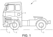
- Figure 1 shows a vehicle in the form of a truck 1 comprising a powertrain system for propulsion of the vehicle 1 via a wheel 5 thereof.
- the truck 1 is provided with an internal combustion engine 2 and an exhaust gas aftertreatment system (EATS) 3.
- a control unit or control system 4 configured to control operation of the truck 1 is also indicated.
- the powertrain system also includes other conventional components that are not shown in the figure, such as a transmission system, drive shafts, etc.
- the powertrain system may instead be electric and comprise an electric motor for driving of the wheels 5.
- the truck 1 may be provided with an electric battery configured to provide electric power to the motor.
- An electric driveline may alternatively or in addition be provided with electricity from fuel cells.
- a fuel cell system may comprise a hydrogen tank.
- the vehicle may be for instance a bus.
- Figure 2 shows a flow chart for a first embodiment of the method comprising the steps of:
- step S3 when step S3 has been performed for the route to be taken, the vehicle may be allowed to drive off from the first location.
- the vehicle 1 when the vehicle 1 is set in the non-drive off mode in step S1, it may still be allowed to move within a starting zone associated with the first location but prevented from moving outside of the starting zone, or it may be prevented from moving away from a stand-still position at the first location. If the non-drive off mode allows the vehicle 1 to move, this mode may comprise allowing the vehicle 1 to drive slowly but not in a speed normally suitable for public roads.
- step S2 may for instance be carried out before step S1.
- step S1 The important thing is that the powertrain system control plan has been established for the route to be taken before the vehicle leaves the starting location.
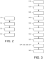
- Figure 3 shows a flow chart for a second embodiment of the method, which is a more detailed example and which comprises the steps of:
- step S20 may for instance be carried out before step S10.
- step S4 can be carried out in a later stage when pre-treating has been carried out. That is, the vehicle may be set in its normal operation mode that allows drive off as late as at the desired starting time for driving off from the first location.
Landscapes
- Engineering & Computer Science (AREA)
- Transportation (AREA)
- Mechanical Engineering (AREA)
- Chemical & Material Sciences (AREA)
- Combustion & Propulsion (AREA)
- Automation & Control Theory (AREA)
- Hybrid Electric Vehicles (AREA)
- Electric Propulsion And Braking For Vehicles (AREA)
Description
- The invention relates to a method for controlling operation of a vehicle comprising a powertrain system for propulsion of the vehicle, wherein the method comprises the steps of: providing information on geographical position of a first (starting) location and a second (destination) location and on length and topography for at least one possible route to be taken by the vehicle from the first location to the second location; and calculating, based on vehicle conditions and on length and topography for the at least one possible route, a plan for how to control the powertrain system to achieve an energy efficient performance of the powertrain system if driving the vehicle along said at least one possible route.
- The invention can typically be applied in trucks and buses, and the powertrain system may be based on an internal combustion engine or an electric motor, or both if a hybrid powertrain system.
- It is of general interest to make a vehicle powertrain system operate as efficiently as possible to, for instance, reduce fuel consumption for combustion engine-based powertrain systems or optimize electricity consumption for an electric driveline/powertrain system. Besides making the various powertrain components work efficiently as such, it is for instance known to make use of a GPS system and map data for a presently driven route to gain information on the upcoming topography, such as the distance to the next significant up- or downhill slope, which can be used to control the powertrain system to achieve an energy efficient performance. For instance, if the temperature of an exhaust gas aftertreatment system of a combustion engine-based powertrain system is about to fall below a critical level, it might be possible to avoid injecting fuel into the exhaust system to raise its temperature (and thus avoid increasing the fuel consumption) and instead wait for reaching an imminent uphill slope where the engine in any case must be operated in a high-load mode that generates high temperature exhaust gas that will heat the exhaust system. For a vehicle with an electric driveline it might instead be useful to know that a long and steep downhill slope is soon to be reached where regenerative braking may be used to charge the battery.
- Although a large number of ways to achieve an energy efficient performance of vehicle powertrain systems have been presented there is still a need for improvements in this field.
- Documents
WO2014/080804A1 ,DE102019103226A1 ,US2011/288737A1 andUS2014/180519A1 describe a method for calculating a plan for controlling the powertrain system of a vehicle along a route in an energy efficient manner. - An object of the invention is to provide a method for controlling operation of a vehicle, which method secures that the vehicle powertrain system can be operated as efficiently as possible. This object is achieved by a method according to
claim 1. Corresponding objects are achieved by a vehicle and by computer-related items according to other aspects of the invention defined in other claims. - The method concerns a method for controlling operation of a vehicle comprising a powertrain system for propulsion of the vehicle, wherein the method comprises the steps of: providing information on geographical position of a first (starting) location and a second (destination) location and on length and topography for at least one possible route to be taken by the vehicle from the first location to the second location; calculating, based on vehicle conditions and on length and topography for the at least one possible route, a plan for how to control the powertrain system to achieve an energy efficient performance of the powertrain system if driving the vehicle along said at least one possible route.
- According to the invention, the method further comprises the steps of: setting the vehicle in a non-drive off mode that prevents the vehicle from driving off from the first location, and setting the vehicle in a normal operation mode that allows drive off from the first location when the step of calculating the plan for how to control the powertrain system has been carried out for the route to be taken by the vehicle.
- The method according to above secures that calculation of how to control the powertrain system in an energy efficient manner is carried out before the vehicle leaves the first location (i.e. the starting location), which secures that the powertrain system can be operated as efficiently as possible when the vehicle travels along the route to the second location (i.e. the destination). Further, in situations where there are several possible routes, the method provides for the possibility to select already at the starting point that route that gives the highest powertrain system energy performance efficiency for the particular vehicle conditions.
- The distance between the first and second location may be tens or hundreds of kilometres and the route may involve both city driving and highway driving.
- The powertrain system may include an internal combustion engine and an associated exhaust gas aftertreatment system, EATS. Alternatively (for an electric vehicle with an electric driveline only) or complementary (for a hybrid vehicle), the powertrain system may include an electric motor and an associated energy storage unit, such as an electric battery. An electric driveline/powertrain system may instead be based on fuel cells for producing electricity to the electric motor. Such a system typically includes a hydrogen storage tank and a complementary electric battery.
- Typically, the first location is the present location of the vehicle, which already is known by a vehicle provided with a GPS or other positioning system. Information on available roads, topography, distance between various points etc. is also normally available for most modern vehicles from stored map data. Thus, input data needed to be supplied to a control system capable of handling route information and calculating how to efficiently control the powertrain system is then primarily the second location, i.e. the destination. Destination information can be supplied to the control system manually by a driver or other person having access to the control system, or it can be supplied in various automatic manners; for instance, predetermined destination(s) may have been registered in the control system in beforehand.
- In many cases it is also useful to supply information on a desired time-of-arrival at the destination to, based on route data, estimate a starting time and evaluate whether the time between present time and starting time should be used to improve performance of the powertrain system before driving off. Such performance improvements include, for instance, using connections to a power grid at the starting location for preheating an EATS (so as to avoid or reduce heating with fuel during driving) or charging or heating a battery before driving off.
- The expression "energy efficient performance of the powertrain" may refer to low or reduced fuel consumption and/or high or increased exhaust gas conversion efficiency for a powertrain system comprising an internal combustion engine, or to a parameter related to battery charging or performance (state of charge needed before departure, battery or fuel cell temperature, possibilities to charge the battery along the route by regenerative braking, etc.) for a powertrain system comprising an electric motor powered by an electric battery (or a fuel cell).
- Knowledge on route length and topography as well as vehicle conditions, such as weight, EATS temperature (or at least of certain components of the EATS), state of charge of battery etc., is required for reliably calculating the plan for how to control the powertrain system to achieve the efficient performance of the powertrain system if driving the vehicle along the route. For instance, steep and long uphill passages and a large vehicle weight lead to long-term high-load operation for the powertrain system which heats up the EATS of a powertrain system provided with an internal combustion engine (due to the large mass rate flow of hot exhaust produced during high-load conditions) or which considerably reduces the state of charge of a battery of a powertrain system provided with an electric driveline. On the other hand, steep and long downhill passages result in cooling down of the EATS, which may require supply of fuel into the EATS to keep the temperature high enough for achieving a sufficiently high conversion efficiency of hazardous compounds in the exhaust gas, and, for an electric driveline, great possibilities to charge the battery using a regenerative braking system (where the electric motor functions as an electric generator).
- For an electric vehicle the plan for how to control the powertrain system may include how to distribute/consume the electricity while travelling along a particular route. Besides supplying electric propulsion power to the electric motor, the electricity may be used for heating, such as heating of the battery, the motor, a cab of a truck or a passenger compartment of a bus. An electric motor may operate more efficiently at certain engine speeds so selection of gear and route may play a role for the efficiency of the powertrain system for an electric vehicle.
- In general the method may comprise taking into account temporary stops during the travel from the first to the second location, such as a stop for refuelling or for charging a battery. For instance, a battery may be preheated during driving before a stop for charging to speed up the charging process. The method may also comprise taking into account what is expected to occur at the second location and after the stop at the second location. For instance, if the stop involves loading/unloading before charging can start it requires a higher state of charge of the battery when arriving at the second location then in a situation where charging can start immediately after arrival.
- The route information may also include e.g. speed limits, expected speed along the route, etc.
- Setting the vehicle in the non-drive off mode may be done in different ways, it may e.g. be a default automatic setting that is activated when the vehicle reaches or is turned off at a destination or it might be activated by other means.
- That the vehicle is "prevented" from driving off does not necessarily mean that it is impossible to drive off (which could be necessary for safety reasons in an emergency situation or be useful for other reasons in other situations) but that the vehicle is prevented from driving off without taking some form of particular action.
- In an embodiment the method further comprises the steps of: providing a desired time-of-arrival at the second location; using the desired time-of-arrival as a boundary condition so as to calculate a desired starting time for driving off from the first location; and determining whether at least part of the time period between present time and the desired starting time can be used for pre-treating the powertrain system so as to achieve a further improvement of performance efficiency of the powertrain system.
- In an embodiment the pre-treating of the powertrain system comprises one or more of the following steps:
- connecting the vehicle to an electric power grid at the first location;
- preheating of one or more components of an exhaust gas aftertreatment system forming part of the powertrain system;
- charging or heating of an electric energy storage unit forming part of the powertrain system; and/or
- preconditioning of a fuel cell.
- Fuel cells typically requires some ventilation, humidification and ramping up before they can operate with full power. Typically, the electric energy from the power grid is thus used for heating, charging or preconditioning. The method may also comprise a pre-treating step involving buffering of a reducing agent (urea).
- In an embodiment the method comprises the steps of: providing information on length and topography for at least two possible routes to be taken by the vehicle from the first location to the second location; calculating, for each of the at least two possible routes and based on vehicle conditions and on length and topography for the at least two possible routes, a plan for how to control the powertrain system to achieve an efficient performance of the powertrain system if driving the vehicle along each of said at least two possible routes, wherein the method further comprises: selecting, before driving off from the first location, one of the at least two possible routes.
- In an embodiment the method further comprises the steps of: determining which one of the at least two possible routes that provides for the most efficient performance of the powertrain system; and selecting, before driving off from the first location, that route that provides for the most efficient performance of the powertrain system.
- Besides length of route, selection of route may depend e.g. on the present conditions of the vehicle. If the vehicle must leave shortly and, for instance, the temperature of the EATS is low it is typically better to select a route that requires high-load operation (e.g. uphill driving) in the beginning and low-load operation at a later stage, and vice versa if the EATS temperature is high before start. As an example for a vehicle with electric driveline and capability to charge its battery by regenerative braking, it is typically an advantage to select a route that starts uphill if the battery is fully charged and use later downhill driving for charging the battery (which then is not fully charged and can thus be charged by regenerative braking).
- In an embodiment the vehicle is positioned at the first location and is connectable to an electric grid at the first location.
- In an embodiment the method comprises the step of: applying the calculated control plan when the vehicle travels towards the second location.
- In an embodiment where pre-treating is contemplated the method comprises the step of: applying the pre-treating of the powertrain system before the vehicle drives off from the first location.
- In an embodiment the vehicle, when set in the non-drive off mode, is allowed to move within a starting zone associated with the first location but prevented from moving outside of the starting zone. Loading/unloading may thus be allowed. The borders of the starting zone may be defined by positioning coordinates and the movement of the vehicle may be controlled using a vehicle control system comprising or communicating with a GPS positioning system arranged onto the vehicle.
- In an embodiment the vehicle, when set in the non-drive off mode, is prevented from moving away from a stand-still position at the first location. This may be achieved by preventing a gear from being (easily) engaged or preventing a brake from being (easily) released. It may also be arranged that the vehicle must be set in a certain operation mode, e.g. a shunting or marshalling mode, where speed, torque and/or power is limited.
- In an embodiment the vehicle, when set in the non-drive off mode, is allowed to drive slowly but not in a speed normally suitable for public roads.
- In another aspect of the invention it relates to a vehicle provided with a powertrain system for propulsion of the vehicle, wherein the vehicle further is provided with a control system configured to perform the method steps according to above.
- In a further aspect of the invention it relates one or more of the following:
- a computer program product comprising program code means for performing the steps of the method above when said program is run on a computer;
- a computer readable medium carrying a computer program comprising program code means for performing the steps of the method above when said program product is run on a computer; and/or
- a control unit for controlling operation of a vehicle comprising a powertrain system for propulsion of the vehicle, the control unit being configured to perform the steps of the above method.
- Further advantages and advantageous features of the invention are disclosed in the following description and in the dependent claims.
- With reference to the appended drawings, below follows a more detailed description of embodiments of the invention cited as examples.
- In the drawings:
-
Fig. 1 shows a truck that may be operated by a method according to this disclosure. -
Fig. 2 shows a flow chart for a first embodiment of the method according to this disclosure. -
Fig. 3 shows a flow chart for a second embodiment of the method according to this disclosure. -
Figure 1 shows a vehicle in the form of atruck 1 comprising a powertrain system for propulsion of thevehicle 1 via awheel 5 thereof. In this schematic example thetruck 1 is provided with aninternal combustion engine 2 and an exhaust gas aftertreatment system (EATS) 3. A control unit orcontrol system 4 configured to control operation of thetruck 1 is also indicated. The powertrain system also includes other conventional components that are not shown in the figure, such as a transmission system, drive shafts, etc. - As an alternative to what is shown in
figure 1 the powertrain system may instead be electric and comprise an electric motor for driving of thewheels 5. In such a case thetruck 1 may be provided with an electric battery configured to provide electric power to the motor. An electric driveline may alternatively or in addition be provided with electricity from fuel cells. A fuel cell system may comprise a hydrogen tank. - As an alternative to the
truck 1 the vehicle may be for instance a bus. -
Figure 2 shows a flow chart for a first embodiment of the method comprising the steps of: - S1 - setting the vehicle in a non-drive off mode that prevents the vehicle from driving off from a first (starting) location;
- S2 - providing information on geographical position of the first (starting) location and a second (destination) location and on length and topography for at least one possible route to be taken by the vehicle from the first location to the second location;
- S3 - calculating, based on vehicle conditions and on length and topography for the at least one possible route, a plan for how to control the powertrain system to achieve an energy efficient performance of the powertrain system if driving the vehicle along said at least one possible route; and
- S4 - setting the vehicle in a normal operation mode that allows drive off from the first location when the step of calculating the plan for how to control the powertrain system has been carried out for the route to be taken by the vehicle.
- Thus, when step S3 has been performed for the route to be taken, the vehicle may be allowed to drive off from the first location.
- As described further above, when the
vehicle 1 is set in the non-drive off mode in step S1, it may still be allowed to move within a starting zone associated with the first location but prevented from moving outside of the starting zone, or it may be prevented from moving away from a stand-still position at the first location. If the non-drive off mode allows thevehicle 1 to move, this mode may comprise allowing thevehicle 1 to drive slowly but not in a speed normally suitable for public roads. - It is not necessary that the steps of the method are carried out in the order indicated in
figure 2 , step S2 may for instance be carried out before step S1. The important thing is that the powertrain system control plan has been established for the route to be taken before the vehicle leaves the starting location. -
Figure 3 shows a flow chart for a second embodiment of the method, which is a more detailed example and which comprises the steps of: - S10 - setting the vehicle in a non-drive off mode that prevents the vehicle from driving off from a first (starting) location;
- S20 - providing information on geographical position of the first (starting) location and a second (destination) location and on length and topography for at least two possible routes to be taken by the vehicle from the first location to the second location;
- S30 - calculating, for each of the at least two possible routes and based on vehicle conditions and on length and topography for the at least two possible routes, a plan for how to control the powertrain system to achieve an efficient performance of the powertrain system if driving the vehicle along each of said at least two possible routes;
- S31 - selecting, before driving off from the first location, one of the at least two possible routes;
- S40 - setting the vehicle in a normal operation mode that allows drive off from the first location when the step of calculating the plan for how to control the powertrain system has been carried out for the selected route.
- S50 - providing a desired time-of-arrival at the second location;
- S51 - using the desired time-of-arrival as a boundary condition so as to calculate a desired starting time for driving off from the first location;
- S52 - determining whether at least part of the time period between present time and the desired starting time can be used for pre-treating the powertrain system so as to achieve a further improvement of performance efficiency of the powertrain system;
- S53 - applying the pre-treating of the powertrain system before the vehicle drives off from the first location by performing one or more of the following steps:.
- S54 - connecting the vehicle to an electric power grid at the first location;
- S55 - preheating of one or more components of an exhaust gas aftertreatment system forming part of the powertrain system;
- S56 - charging or heating of an electric energy storage unit forming part of the powertrain system, and/or
- S57 - preconditioning of a fuel cell forming part of the powertrain system.
- S60 - applying the calculated control plan when the vehicle travels towards the second location.
- As in the previous example it is not necessary that the steps of the method are carried out exactly in the order indicated in
figure 3 , step S20 may for instance be carried out before step S10. In a variant of the example offigure 3 step S4 can be carried out in a later stage when pre-treating has been carried out. That is, the vehicle may be set in its normal operation mode that allows drive off as late as at the desired starting time for driving off from the first location. - It is to be understood that the present invention is not limited to the embodiments described above and illustrated in the drawings; rather, the skilled person will recognize that many changes and modifications may be made within the scope of the appended claims.
Claims (15)
- A method for controlling operation of a vehicle (1) comprising a powertrain system (2, 3) for propulsion of the vehicle (1),wherein the method comprises the steps of:- providing (S2, S20) information on geographical position of a first (starting) location and a second (destination) location and on length and topography for at least one possible route to be taken by the vehicle (1) from the first location to the second location;- calculating (S3, S30), based on vehicle conditions and on length and topography for the at least one possible route, a plan for how to control the powertrain system to achieve an energy efficient performance of the powertrain system (2, 3) if driving the vehicle (1) along said at least one possible route,characterized inthat the method comprises the steps of:- setting (S1, S10) the vehicle (1) in a non-drive off mode that prevents the vehicle from driving off from the first location, and- setting (S4, S40) the vehicle (1) in a normal operation mode that allows drive off from the first location when the step of calculating the plan for how to control the powertrain system (2, 3) has been carried out for the route to be taken by the vehicle (1).
- The method according to claim 1, wherein the method further comprises:- providing a desired time-of-arrival at the second location;- using the desired time-of-arrival as a boundary condition so as to calculate a desired starting time for driving off from the first location;- determining whether at least part of the time period between present time and the desired starting time can be used for pre-treating the powertrain system so as to achieve a further improvement of performance efficiency of the powertrain system.
- The method according to claim 2, wherein the pre-treating of the powertrain system comprises one or more of the following steps:- connecting the vehicle to an electric power grid at the first location;- preheating of one or more components of an exhaust gas aftertreatment system forming part of the powertrain system;- charging or heating of an electric energy storage unit forming part of the powertrain system; and/or- preconditioning of a fuel cell forming part of the powertrain system.
- The method according to any of the above claims, wherein the method comprises the steps of:- providing information on length and topography for at least two possible routes to be taken by the vehicle from the first location to the second location;- calculating, for each of the at least two possible routes and based on vehicle conditions and on length and topography for the at least two possible routes, a plan for how to control the powertrain system to achieve an efficient performance of the powertrain system if driving the vehicle along each of said at least two possible routes,wherein the method further comprises:- selecting, before driving off from the first location, one of the at least two possible routes.
- The method according to claim 4, wherein the method comprises the steps of:- determining which one of the at least two possible routes that provides for the most efficient performance of the powertrain system; and- selecting, before driving off from the first location, that route that provides for the most efficient performance of the powertrain system.
- The method according to any of the above claims, wherein the vehicle is positioned at the first location and is connectable to an electric grid at the first location.
- The method according to any of the above claims, wherein the method comprises the step of:- applying the calculated control plan when the vehicle travels towards the second location.
- The method according to claim 2 or 3, wherein the method comprises the step of:- applying the pre-treating of the powertrain system before the vehicle drives off from the first location.
- The method according to any of the above claims, wherein the vehicle, when set in the non-drive off mode, is allowed to move within a starting zone associated with the first location but prevented from moving outside of the starting zone.
- The method according to any of claims 1-8, wherein the vehicle, when set in the non-drive off mode, is prevented from moving away from a stand-still position at the first location.
- The method according to any of claims 1-8, wherein the vehicle, when set in the non-drive off mode, is allowed to drive slowly but not in a speed normally suitable for public roads.
- A vehicle provided with a powertrain system for propulsion of the vehicle, wherein the vehicle further is provided with the control unit according to claim 15.
- A computer program product comprising program code means for performing the steps of any of claims 1-11 when said program code is run on a computer
- A computer readable medium carrying the computer program product according to claim 13.
- A control unit for controlling operation of a vehicle comprising a powertrain system for propulsion of the vehicle, the control unit being configured to perform the steps of the method according to any of claims 1-11.
Applications Claiming Priority (1)
| Application Number | Priority Date | Filing Date | Title |
|---|---|---|---|
| PCT/EP2020/050081 WO2021136597A1 (en) | 2020-01-03 | 2020-01-03 | Method for controlling operation of a vehicle |
Publications (3)
| Publication Number | Publication Date |
|---|---|
| EP4084998A1 EP4084998A1 (en) | 2022-11-09 |
| EP4084998B1 true EP4084998B1 (en) | 2024-02-07 |
| EP4084998C0 EP4084998C0 (en) | 2024-02-07 |
Family
ID=69165337
Family Applications (1)
| Application Number | Title | Priority Date | Filing Date |
|---|---|---|---|
| EP20700637.0A Active EP4084998B1 (en) | 2020-01-03 | 2020-01-03 | Method for controlling operation of a vehicle |
Country Status (4)
| Country | Link |
|---|---|
| US (1) | US20230061155A1 (en) |
| EP (1) | EP4084998B1 (en) |
| CN (1) | CN114845911A (en) |
| WO (1) | WO2021136597A1 (en) |
Family Cites Families (27)
| Publication number | Priority date | Publication date | Assignee | Title |
|---|---|---|---|---|
| DE3831449A1 (en) * | 1988-09-16 | 1990-03-22 | Man Nutzfahrzeuge Ag | Electronic operational control system for a drive train of a motor vehicle |
| JPH08237810A (en) * | 1995-02-27 | 1996-09-13 | Aqueous Res:Kk | Hybrid vehicle |
| JP2001234840A (en) * | 2000-02-25 | 2001-08-31 | Hitachi Ltd | Hybrid car |
| US7343232B2 (en) * | 2003-06-20 | 2008-03-11 | Geneva Aerospace | Vehicle control system including related methods and components |
| US20050228553A1 (en) * | 2004-03-30 | 2005-10-13 | Williams International Co., L.L.C. | Hybrid Electric Vehicle Energy Management System |
| US7974774B2 (en) * | 2006-03-20 | 2011-07-05 | General Electric Company | Trip optimization system and method for a vehicle |
| US9527518B2 (en) * | 2006-03-20 | 2016-12-27 | General Electric Company | System, method and computer software code for controlling a powered system and operational information used in a mission by the powered system |
| US9552728B2 (en) * | 2010-05-19 | 2017-01-24 | General Motors Llc | Route-based propulsion mode control for multimodal vehicles |
| WO2013038492A1 (en) * | 2011-09-13 | 2013-03-21 | トヨタ自動車株式会社 | Vehicle control device and control method |
| US8813881B2 (en) * | 2012-05-04 | 2014-08-26 | Ford Global Technologies, Llc | Methods and systems for a vehicle driveline power take off |
| WO2014080804A1 (en) * | 2012-11-26 | 2014-05-30 | 日産自動車株式会社 | Control device for vehicle |
| US11209286B2 (en) * | 2013-02-26 | 2021-12-28 | Polaris Industies Inc. | Recreational vehicle interactive telemetry, mapping and trip planning system |
| EP2962064B1 (en) * | 2013-02-26 | 2018-04-04 | Polaris Industries Inc. | Recreational vehicle interactive telemetry, mapping, and trip planning system |
| JP5860831B2 (en) * | 2013-03-29 | 2016-02-16 | アイシン・エィ・ダブリュ株式会社 | Driving support system, driving support method, and computer program |
| US9605606B2 (en) * | 2014-03-31 | 2017-03-28 | Toyota Motor Engineering & Manufacturing North America, Inc. | System and method for improving energy efficiency of a vehicle based on determined relationships between a plurality of routes |
| US9695760B2 (en) * | 2014-03-31 | 2017-07-04 | Toyota Motor Engineering & Manufacturing North America, Inc. | System and method for improving energy efficiency of a vehicle based on known route segments |
| US9676382B2 (en) * | 2014-04-17 | 2017-06-13 | Palo Alto Research Center Incorporated | Systems and methods for hybrid vehicles with a high degree of hybridization |
| WO2015197094A1 (en) * | 2014-06-27 | 2015-12-30 | Volvo Truck Corporation | A method for controlling state of charge of a plug-in hybrid vehicle |
| JP6180458B2 (en) * | 2015-04-17 | 2017-08-16 | 三菱電機株式会社 | Vehicle energy management system |
| US9536149B1 (en) * | 2016-02-04 | 2017-01-03 | Proxy Technologies, Inc. | Electronic assessments, and methods of use and manufacture thereof |
| US10699305B2 (en) * | 2016-11-21 | 2020-06-30 | Nio Usa, Inc. | Smart refill assistant for electric vehicles |
| WO2018140366A1 (en) * | 2017-01-25 | 2018-08-02 | Cummins Inc. | Systems and methods for predictive gear shifting and integrated predictive cruise control |
| US10392002B2 (en) * | 2017-09-07 | 2019-08-27 | Ford Global Technologies, Llc | Methods and systems for controlling engine idle-stop |
| US20190107406A1 (en) * | 2017-10-09 | 2019-04-11 | Nio Usa, Inc. | Systems and methods for trip planning under uncertainty |
| US10788845B2 (en) * | 2017-12-01 | 2020-09-29 | Cummins Inc. | Optimization of mission efficiency through platoon opportunity assessment |
| US10960873B2 (en) * | 2018-02-13 | 2021-03-30 | Ford Global Technologies, Llc | System and method for a range extender engine of a hybrid electric vehicle |
| US11192548B2 (en) * | 2019-03-25 | 2021-12-07 | Ford Global Technologies, Llc | Methods and systems for limiting a vehicle speed and changing vehicle dynamics drive mode |
-
2020
- 2020-01-03 US US17/790,664 patent/US20230061155A1/en not_active Abandoned
- 2020-01-03 WO PCT/EP2020/050081 patent/WO2021136597A1/en not_active Ceased
- 2020-01-03 CN CN202080089620.0A patent/CN114845911A/en active Pending
- 2020-01-03 EP EP20700637.0A patent/EP4084998B1/en active Active
Also Published As
| Publication number | Publication date |
|---|---|
| WO2021136597A1 (en) | 2021-07-08 |
| EP4084998C0 (en) | 2024-02-07 |
| CN114845911A (en) | 2022-08-02 |
| EP4084998A1 (en) | 2022-11-09 |
| US20230061155A1 (en) | 2023-03-02 |
Similar Documents
| Publication | Publication Date | Title |
|---|---|---|
| CN103029595B (en) | The system and method driving for controlling the upward slope of electric motor car | |
| US10545503B2 (en) | Propulsion efficient autonomous driving strategy | |
| CN106560361B (en) | Method and apparatus for controlling hybrid electric vehicle | |
| EP2847054B1 (en) | Energy management system and fuel saving method for a hybrid electric vehicle | |
| CN103770776B (en) | Motor vehicle driven by mixed power is set to postpone pure electric operating | |
| US9043060B2 (en) | Methods, systems, and apparatuses for driveline load management | |
| JP2003047110A (en) | Method of using on-board navigation system for hybrid electric vehicle for vehicle energy management | |
| US9796290B2 (en) | Method and apparatus of controlling output voltage of DC converter for vehicle including driving motor | |
| CN102442262B (en) | The energy efficient control of air-conditioning system | |
| CN107757603A (en) | automatic driving mode selection | |
| US20230304809A1 (en) | Power management of industrial electric vehicles | |
| SE1150074A1 (en) | Method for determining a braking position for a regenerative braking of a vehicle, device, braking system and vehicle | |
| CN105292100A (en) | Apparatus and method for controlling engine clutch of hybrid electric vehicle | |
| van der Put et al. | Efficient commercial powertrains–How to achieve a 30% GHG reduction in 2030 | |
| CN108501952A (en) | For changing the system and method for start and stop event | |
| Hasan et al. | Energy management strategy in electric buses for public transport using ECO-driving | |
| JP2017081356A (en) | Electric car control device | |
| US20240351480A1 (en) | Method for intelligent heating of a fuel cell system and vehicle | |
| US20230061155A1 (en) | Method for controlling operation of a vehicle | |
| JP2016175498A (en) | Hybrid vehicle and its control device | |
| US11654886B2 (en) | Driving assistance system and driving assistance method | |
| JP6495793B2 (en) | Control device and control method for electric vehicle | |
| CN102407768B (en) | Compact stroke increasing electric vehicle capable of disengaging from engine and control method thereof | |
| JP6788942B1 (en) | Energy-saving deceleration driving support method | |
| Leska et al. | Optimal trajectory planning for standard and hybrid railway vehicles with a hydro-mechanic transmission |
Legal Events
| Date | Code | Title | Description |
|---|---|---|---|
| STAA | Information on the status of an ep patent application or granted ep patent |
Free format text: STATUS: UNKNOWN |
|
| STAA | Information on the status of an ep patent application or granted ep patent |
Free format text: STATUS: THE INTERNATIONAL PUBLICATION HAS BEEN MADE |
|
| PUAI | Public reference made under article 153(3) epc to a published international application that has entered the european phase |
Free format text: ORIGINAL CODE: 0009012 |
|
| STAA | Information on the status of an ep patent application or granted ep patent |
Free format text: STATUS: REQUEST FOR EXAMINATION WAS MADE |
|
| 17P | Request for examination filed |
Effective date: 20220705 |
|
| AK | Designated contracting states |
Kind code of ref document: A1 Designated state(s): AL AT BE BG CH CY CZ DE DK EE ES FI FR GB GR HR HU IE IS IT LI LT LU LV MC MK MT NL NO PL PT RO RS SE SI SK SM TR |
|
| DAV | Request for validation of the european patent (deleted) | ||
| DAX | Request for extension of the european patent (deleted) | ||
| GRAP | Despatch of communication of intention to grant a patent |
Free format text: ORIGINAL CODE: EPIDOSNIGR1 |
|
| STAA | Information on the status of an ep patent application or granted ep patent |
Free format text: STATUS: GRANT OF PATENT IS INTENDED |
|
| INTG | Intention to grant announced |
Effective date: 20230803 |
|
| GRAS | Grant fee paid |
Free format text: ORIGINAL CODE: EPIDOSNIGR3 |
|
| RIN1 | Information on inventor provided before grant (corrected) |
Inventor name: LUNDIN, LARS Inventor name: WILHELMSSON, MARTIN Inventor name: ERIKSSON, ANDERS |
|
| GRAA | (expected) grant |
Free format text: ORIGINAL CODE: 0009210 |
|
| STAA | Information on the status of an ep patent application or granted ep patent |
Free format text: STATUS: THE PATENT HAS BEEN GRANTED |
|
| AK | Designated contracting states |
Kind code of ref document: B1 Designated state(s): AL AT BE BG CH CY CZ DE DK EE ES FI FR GB GR HR HU IE IS IT LI LT LU LV MC MK MT NL NO PL PT RO RS SE SI SK SM TR |
|
| REG | Reference to a national code |
Ref country code: GB Ref legal event code: FG4D |
|
| REG | Reference to a national code |
Ref country code: CH Ref legal event code: EP |
|
| REG | Reference to a national code |
Ref country code: IE Ref legal event code: FG4D |
|
| REG | Reference to a national code |
Ref country code: DE Ref legal event code: R096 Ref document number: 602020025306 Country of ref document: DE |
|
| U01 | Request for unitary effect filed |
Effective date: 20240304 |
|
| U07 | Unitary effect registered |
Designated state(s): AT BE BG DE DK EE FI FR IT LT LU LV MT NL PT SE SI Effective date: 20240311 |
|
| PG25 | Lapsed in a contracting state [announced via postgrant information from national office to epo] |
Ref country code: IS Free format text: LAPSE BECAUSE OF FAILURE TO SUBMIT A TRANSLATION OF THE DESCRIPTION OR TO PAY THE FEE WITHIN THE PRESCRIBED TIME-LIMIT Effective date: 20240607 |
|
| PG25 | Lapsed in a contracting state [announced via postgrant information from national office to epo] |
Ref country code: GR Free format text: LAPSE BECAUSE OF FAILURE TO SUBMIT A TRANSLATION OF THE DESCRIPTION OR TO PAY THE FEE WITHIN THE PRESCRIBED TIME-LIMIT Effective date: 20240508 |
|
| PG25 | Lapsed in a contracting state [announced via postgrant information from national office to epo] |
Ref country code: RS Free format text: LAPSE BECAUSE OF FAILURE TO SUBMIT A TRANSLATION OF THE DESCRIPTION OR TO PAY THE FEE WITHIN THE PRESCRIBED TIME-LIMIT Effective date: 20240507 Ref country code: HR Free format text: LAPSE BECAUSE OF FAILURE TO SUBMIT A TRANSLATION OF THE DESCRIPTION OR TO PAY THE FEE WITHIN THE PRESCRIBED TIME-LIMIT Effective date: 20240207 |
|
| PG25 | Lapsed in a contracting state [announced via postgrant information from national office to epo] |
Ref country code: ES Free format text: LAPSE BECAUSE OF FAILURE TO SUBMIT A TRANSLATION OF THE DESCRIPTION OR TO PAY THE FEE WITHIN THE PRESCRIBED TIME-LIMIT Effective date: 20240207 |
|
| PG25 | Lapsed in a contracting state [announced via postgrant information from national office to epo] |
Ref country code: RS Free format text: LAPSE BECAUSE OF FAILURE TO SUBMIT A TRANSLATION OF THE DESCRIPTION OR TO PAY THE FEE WITHIN THE PRESCRIBED TIME-LIMIT Effective date: 20240507 Ref country code: NO Free format text: LAPSE BECAUSE OF FAILURE TO SUBMIT A TRANSLATION OF THE DESCRIPTION OR TO PAY THE FEE WITHIN THE PRESCRIBED TIME-LIMIT Effective date: 20240507 Ref country code: IS Free format text: LAPSE BECAUSE OF FAILURE TO SUBMIT A TRANSLATION OF THE DESCRIPTION OR TO PAY THE FEE WITHIN THE PRESCRIBED TIME-LIMIT Effective date: 20240607 Ref country code: HR Free format text: LAPSE BECAUSE OF FAILURE TO SUBMIT A TRANSLATION OF THE DESCRIPTION OR TO PAY THE FEE WITHIN THE PRESCRIBED TIME-LIMIT Effective date: 20240207 Ref country code: GR Free format text: LAPSE BECAUSE OF FAILURE TO SUBMIT A TRANSLATION OF THE DESCRIPTION OR TO PAY THE FEE WITHIN THE PRESCRIBED TIME-LIMIT Effective date: 20240508 Ref country code: ES Free format text: LAPSE BECAUSE OF FAILURE TO SUBMIT A TRANSLATION OF THE DESCRIPTION OR TO PAY THE FEE WITHIN THE PRESCRIBED TIME-LIMIT Effective date: 20240207 |
|
| PG25 | Lapsed in a contracting state [announced via postgrant information from national office to epo] |
Ref country code: PL Free format text: LAPSE BECAUSE OF FAILURE TO SUBMIT A TRANSLATION OF THE DESCRIPTION OR TO PAY THE FEE WITHIN THE PRESCRIBED TIME-LIMIT Effective date: 20240207 |
|
| PG25 | Lapsed in a contracting state [announced via postgrant information from national office to epo] |
Ref country code: PL Free format text: LAPSE BECAUSE OF FAILURE TO SUBMIT A TRANSLATION OF THE DESCRIPTION OR TO PAY THE FEE WITHIN THE PRESCRIBED TIME-LIMIT Effective date: 20240207 |
|
| PG25 | Lapsed in a contracting state [announced via postgrant information from national office to epo] |
Ref country code: SM Free format text: LAPSE BECAUSE OF FAILURE TO SUBMIT A TRANSLATION OF THE DESCRIPTION OR TO PAY THE FEE WITHIN THE PRESCRIBED TIME-LIMIT Effective date: 20240207 |
|
| PG25 | Lapsed in a contracting state [announced via postgrant information from national office to epo] |
Ref country code: CZ Free format text: LAPSE BECAUSE OF FAILURE TO SUBMIT A TRANSLATION OF THE DESCRIPTION OR TO PAY THE FEE WITHIN THE PRESCRIBED TIME-LIMIT Effective date: 20240207 |
|
| PG25 | Lapsed in a contracting state [announced via postgrant information from national office to epo] |
Ref country code: SK Free format text: LAPSE BECAUSE OF FAILURE TO SUBMIT A TRANSLATION OF THE DESCRIPTION OR TO PAY THE FEE WITHIN THE PRESCRIBED TIME-LIMIT Effective date: 20240207 |
|
| PG25 | Lapsed in a contracting state [announced via postgrant information from national office to epo] |
Ref country code: SM Free format text: LAPSE BECAUSE OF FAILURE TO SUBMIT A TRANSLATION OF THE DESCRIPTION OR TO PAY THE FEE WITHIN THE PRESCRIBED TIME-LIMIT Effective date: 20240207 Ref country code: SK Free format text: LAPSE BECAUSE OF FAILURE TO SUBMIT A TRANSLATION OF THE DESCRIPTION OR TO PAY THE FEE WITHIN THE PRESCRIBED TIME-LIMIT Effective date: 20240207 Ref country code: RO Free format text: LAPSE BECAUSE OF FAILURE TO SUBMIT A TRANSLATION OF THE DESCRIPTION OR TO PAY THE FEE WITHIN THE PRESCRIBED TIME-LIMIT Effective date: 20240207 Ref country code: CZ Free format text: LAPSE BECAUSE OF FAILURE TO SUBMIT A TRANSLATION OF THE DESCRIPTION OR TO PAY THE FEE WITHIN THE PRESCRIBED TIME-LIMIT Effective date: 20240207 |
|
| REG | Reference to a national code |
Ref country code: DE Ref legal event code: R097 Ref document number: 602020025306 Country of ref document: DE |
|
| PLBE | No opposition filed within time limit |
Free format text: ORIGINAL CODE: 0009261 |
|
| STAA | Information on the status of an ep patent application or granted ep patent |
Free format text: STATUS: NO OPPOSITION FILED WITHIN TIME LIMIT |
|
| 26N | No opposition filed |
Effective date: 20241108 |
|
| U20 | Renewal fee for the european patent with unitary effect paid |
Year of fee payment: 6 Effective date: 20250127 |
|
| REG | Reference to a national code |
Ref country code: CH Ref legal event code: PL |
|
| PG25 | Lapsed in a contracting state [announced via postgrant information from national office to epo] |
Ref country code: MC Free format text: LAPSE BECAUSE OF FAILURE TO SUBMIT A TRANSLATION OF THE DESCRIPTION OR TO PAY THE FEE WITHIN THE PRESCRIBED TIME-LIMIT Effective date: 20240207 |
|
| GBPC | Gb: european patent ceased through non-payment of renewal fee |
Effective date: 20250103 |
|
| PG25 | Lapsed in a contracting state [announced via postgrant information from national office to epo] |
Ref country code: GB Free format text: LAPSE BECAUSE OF NON-PAYMENT OF DUE FEES Effective date: 20250103 |
|
| PG25 | Lapsed in a contracting state [announced via postgrant information from national office to epo] |
Ref country code: CH Free format text: LAPSE BECAUSE OF NON-PAYMENT OF DUE FEES Effective date: 20250131 |
|
| PG25 | Lapsed in a contracting state [announced via postgrant information from national office to epo] |
Ref country code: IE Free format text: LAPSE BECAUSE OF NON-PAYMENT OF DUE FEES Effective date: 20250103 |