EP4084589A1 - Computing unit for a hpc cabinet and method for accessing an electronic component from the computing unit - Google Patents
Computing unit for a hpc cabinet and method for accessing an electronic component from the computing unit Download PDFInfo
- Publication number
- EP4084589A1 EP4084589A1 EP21170707.0A EP21170707A EP4084589A1 EP 4084589 A1 EP4084589 A1 EP 4084589A1 EP 21170707 A EP21170707 A EP 21170707A EP 4084589 A1 EP4084589 A1 EP 4084589A1
- Authority
- EP
- European Patent Office
- Prior art keywords
- computing unit
- external body
- wall
- internal body
- latching
- Prior art date
- Legal status (The legal status is an assumption and is not a legal conclusion. Google has not performed a legal analysis and makes no representation as to the accuracy of the status listed.)
- Granted
Links
Images



Classifications
-
- H—ELECTRICITY
- H05—ELECTRIC TECHNIQUES NOT OTHERWISE PROVIDED FOR
- H05K—PRINTED CIRCUITS; CASINGS OR CONSTRUCTIONAL DETAILS OF ELECTRIC APPARATUS; MANUFACTURE OF ASSEMBLAGES OF ELECTRICAL COMPONENTS
- H05K7/00—Constructional details common to different types of electric apparatus
- H05K7/14—Mounting supporting structure in casing or on frame or rack
- H05K7/1485—Servers; Data center rooms, e.g. 19-inch computer racks
- H05K7/1487—Blade assemblies, e.g. blade cases or inner arrangements within a blade
-
- H—ELECTRICITY
- H05—ELECTRIC TECHNIQUES NOT OTHERWISE PROVIDED FOR
- H05K—PRINTED CIRCUITS; CASINGS OR CONSTRUCTIONAL DETAILS OF ELECTRIC APPARATUS; MANUFACTURE OF ASSEMBLAGES OF ELECTRICAL COMPONENTS
- H05K5/00—Casings, cabinets or drawers for electric apparatus
- H05K5/02—Details
- H05K5/0217—Mechanical details of casings
- H05K5/0221—Locks; Latches
-
- H—ELECTRICITY
- H05—ELECTRIC TECHNIQUES NOT OTHERWISE PROVIDED FOR
- H05K—PRINTED CIRCUITS; CASINGS OR CONSTRUCTIONAL DETAILS OF ELECTRIC APPARATUS; MANUFACTURE OF ASSEMBLAGES OF ELECTRICAL COMPONENTS
- H05K7/00—Constructional details common to different types of electric apparatus
- H05K7/14—Mounting supporting structure in casing or on frame or rack
- H05K7/1401—Mounting supporting structure in casing or on frame or rack comprising clamping or extracting means
- H05K7/1402—Mounting supporting structure in casing or on frame or rack comprising clamping or extracting means for securing or extracting printed circuit boards
- H05K7/1409—Mounting supporting structure in casing or on frame or rack comprising clamping or extracting means for securing or extracting printed circuit boards by lever-type mechanisms
-
- H—ELECTRICITY
- H05—ELECTRIC TECHNIQUES NOT OTHERWISE PROVIDED FOR
- H05K—PRINTED CIRCUITS; CASINGS OR CONSTRUCTIONAL DETAILS OF ELECTRIC APPARATUS; MANUFACTURE OF ASSEMBLAGES OF ELECTRICAL COMPONENTS
- H05K7/00—Constructional details common to different types of electric apparatus
- H05K7/14—Mounting supporting structure in casing or on frame or rack
- H05K7/1485—Servers; Data center rooms, e.g. 19-inch computer racks
- H05K7/1488—Cabinets therefor, e.g. chassis or racks or mechanical interfaces between blades and support structures
- H05K7/1489—Cabinets therefor, e.g. chassis or racks or mechanical interfaces between blades and support structures characterized by the mounting of blades therein, e.g. brackets, rails, trays
-
- H—ELECTRICITY
- H05—ELECTRIC TECHNIQUES NOT OTHERWISE PROVIDED FOR
- H05K—PRINTED CIRCUITS; CASINGS OR CONSTRUCTIONAL DETAILS OF ELECTRIC APPARATUS; MANUFACTURE OF ASSEMBLAGES OF ELECTRICAL COMPONENTS
- H05K7/00—Constructional details common to different types of electric apparatus
- H05K7/14—Mounting supporting structure in casing or on frame or rack
- H05K7/1485—Servers; Data center rooms, e.g. 19-inch computer racks
- H05K7/1488—Cabinets therefor, e.g. chassis or racks or mechanical interfaces between blades and support structures
- H05K7/1492—Cabinets therefor, e.g. chassis or racks or mechanical interfaces between blades and support structures having electrical distribution arrangements, e.g. power supply or data communications
Definitions
- the present invention relates, in general, to a high-performance computing and, more specifically relates, to a computing unit for a high-performance computing cabinet and a method for accessing an electronic component from the computing unit.
- a datacenter comprises several high-performance computing cabinets, called HPC cabinets or “clusters”, arranged in rows within the datacenter and configured to house computing units, such as servers, switches and routers, to organize, process and store data.
- Each computing unit comprises conventionally at least one mother board and several components secured to the mother board such as processors, Dual In-Line Memory Module (DIMM), a PCIe component (GPU, FPGAs)), fans, etc.
- DIMM Dual In-Line Memory Module
- PCIe component GPU, FPGAs
- Ultra Path Interconnect UPI
- users face several issues which either require a maintenance activity to be carried out on the computing units and may often include replacement of few components in the computing units.
- a HPC cabinet comprises traditionally two vertical side walls delimiting a central cavity with a front opening, so as to define vertically stacked sockets having a standard height (U).
- a computing unit is configured to be housed in the HPC cabinet and mounted onto the two vertical side walls.
- the height of the computing device is usually comprised between 1U and 6U.
- Each vertical side wall comprises a front portion which is configured to cooperate with an abutment wall of the computing unit.
- the front portion of each side wall comprises threaded openings and the abutment wall of the computing unit comprises screws which are configured to be screwed into the threaded openings so that the computing unit is secured fixedly to the HPC cabinet.
- each computing unit is also connected to a power distribution unit, known as PDU, and to a network thanks to a management node (not represented) located within the HPC cabinet.
- a computing unit configured to be mounted in a High-Performance Computing cabinet, thereafter HPC cabinet, defining a plurality of vertically stacked sockets, the computing unit comprising:
- the computing unit can be secured fixedly to the HPC cabinet as in the prior art but the internal body can be pulled out without requiring removing the external body.
- the use of a front lever avoids using tools which increases maintenance efficiency.
- the use of two matching points for each front lever allows performing a tight coupling without hardship for the user.
- the latching wall comprises at least a reception element, located on the back face of the latching wall, configured to cooperate with the front lever.
- the reception element can retain the front lever which acts as a hook.
- the latching wall comprises at least one through opening, preferably a notch, said reception element being located at the periphery of the through opening.
- the front lever can therefore move within the through opening before being retained by the reception element.
- the abutment wall comprises at least a locking member accessible from the front of the computing unit through the through opening of the latching wall.
- the locking member is always accessible even with the presence of the latching wall.
- the front lever comprises at least an actuator comprising a first end for cooperating with the latching wall and a second end configured to be manipulated manually by a user without tools so that to modify the inclination of the actuator, the actuator being pivotable between an engaged position for securing the internal body to the external body and a disengaged position. Any accidental removal of the internal body is therefore avoided.
- the front lever comprises at least a biasing member configured to retain the actuator in the engaged position.
- the bottom wall comprises at least a through opening and the front lever comprises at least a latching tooth configured to cooperate with the through opening in order to push the internal body within the external body when rotating the front lever to the rear.
- the front lever comprises a bottom arm configured to latch with the bottom wall and a top arm configured to latch with the latching wall of the external body.
- the bottom arm and the top arm of the front lever are laterally offset.
- the computing unit comprises two front levers, one at each side of the internal body so that the front levers can be used simultaneously to pull the internal body.
- the invention relates also to a method for accessing a second electronic component from the internal body of a computing unit as presented before, the internal body being located in the housing of the external body, the front lever being latched with the latching wall of the external body, the method comprising:
- a datacenter comprises several high-performance computing cabinets, called HPC cabinets or “clusters”, arranged in rows within the datacenter and configured to house computing units, such as servers, switches and routers, to organize, process and store data.
- HPC cabinet is configured to accommodate multiple server units, switches, cords and cables, rails, cable management bars, routers, path panels, and blanking panels.
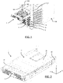
- a HPC cabinet 100 comprises two vertical side walls 101, delimiting a central cavity with a front opening, so as to define vertically stacked sockets S having a standard height (U).
- Several computing units 1 are housed in the HPC cabinet 100 and mounted onto the two vertical side walls 101.
- the height of each computing device 1 is 2U but could be different.
- Each vertical side wall 101 comprises a front portion which is configured to cooperate with an abutment wall of a computing unit 1.
- the front portion of each side wall 101 comprises threaded openings 102.
- Such an HPC cabinet 100 is known from the prior art and won't be further detailed.
- the computing unit 1 comprises an internal body 3 mounted within an external body 2, the internal body 3 being releasably coupled to the external body 2 in order to allow extraction of the internal body 3 when the external body 2 is fixedly secured to the HPC cabinet 100.
- the computing unit 1 is presented in the (X, Y, Z) referential in which the X axis extends longitudinally from the front to the rear, the Y axis extends laterally from the right to the left and the Z axis extends vertically from the bottom to the top.
- the external body 2 comprise lateral walls 22, a bottom wall 23 (See Figure 4 ) and a top wall 21 defining together a housing (the top wall 21 is not represented in the figures 3 and 4 ).
- the external body 2 defines a front housing H1 where the internal body 3 can be mounted and a back housing H2 where primary electronic components C1 are located, for example, at least one mother board and components secured to the mother board such as processors, Dual In-Line Memory Module (DIMM), etc.
- the internal body 3 is configured to be releasably coupled to the primary electronic components C1 from the back housing H2.
- the external body 2 comprises at least a first connector K1 connected to the primary electronic components C1.
- the first connector K1 is located at the interface between the first housing H1 and the second housing H2.
- each lateral wall 22 of the external body 2 comprises an abutment wall 4 configured to be connected to the HPC cabinet 100.
- Each abutment wall 4 is located in a front end of the external body 2.
- the abutment wall 4 from the right side will be now described in reference to Figure 5 .
- the description of the left side is similar and won't be presented in details.
- the abutment wall 4 extends laterally to the right from the side wall 22.
- the abutment wall 4 extends vertically in a YZ plane as represented in Figure 5 , preferably along the entire height of the computing unit 1.
- the abutment wall 4 comprises a locking member 41, preferably, a captive screw.
- the abutment wall 4 is configured to abut to a vertical side wall 101 of the HPC cabinet 100 which comprises several threaded openings 102 in order to retain the locking member 41.
- the external body 2 can be secured fixedly to the HPC cabinet 100 as in the prior art.
- the external body 2 comprises also a latching wall 5 extending in front of the abutment wall 4.
- the latching wall 5 and the abutment wall 4 are longitudinally spaced apart from a distance L, defined along the X axis, which is comprised between 14 and 22 mm, preferably 18 mm.
- the latching wall 5 is parallel to the abutment wall 4 and extends preferably along the entire height of the computing unit 1. In this example, the latching wall 5 and the abutment wall 4 are fixed relatively to each other.
- the latching wall 5 comprises a trough opening 51, preferably a cutout or a notch, which is aligned longitudinally, along the X axis, with the locking member 41 from the abutment wall 4.
- a user can therefore access the locking member 41 from the front, for example with a screwdriver, in order to secure the external body 2 to the HPC cabinet 100. Thanks to the invention, this operation is performed only during the first mounting or for heavy maintenance.
- the latching wall 5 also comprises a reception element 52, located on the back face of the latching wall 5, configured to cooperate with a front lever 8 according to the invention.
- the reception element 52 is located at the periphery of the trough opening 51.
- the reception element 52 is preferably located directly over the through opening 51.
- the reception element 52 defines a recess in the back face of the latching wall 5 so that a part of the front lever 8 can be securely located in the recess when the internal body 3 and the external body 2 are coupled together.
- the external body 2 comprises also a through opening 230 located on each side of the bottom wall 23 of the external body 2 so that each front lever 8 can latch with the external body 2 according to two latching points.
- the cooperation of the internal body 3 with the external body 2 is very stable even with the releasable coupling.
- the internal body 3 comprises a bottom wall 31 and side walls 32.
- the internal body 3 further comprises a motherboard connected to several secondary electronic components C2.
- the internal body 3 comprises for example, processors, Dual In-Line Memory Module (DIMM), a PCIe component (GPU, FPGAs)), fans.
- DIMM Dual In-Line Memory Module
- GPU PCIe component
- FPGAs FPGAs
- the internal body 3 comprises at least a second connector K2 connected to the secondary electronic components C2; the second connector K2 being configured to cooperate with the first connector K1 when the internal body 2 is coupled with the external body 3 (See Figure 3 ).
- the second connector K2 is located at the rear end of the internal body 3.
- the computing unit 1 comprises, at each side of the internal body 3, a front lever 8 pivotally coupled to the internal body 3 and configured to latch:
- the internal body 3 comprises two front levers 8 capable of being pivotably deflected by a user to allow detachment of the internal body 3 from the external body 2. Likewise, the front levers 8 also enable the user to push the internal body 3 back into the external body 2. The front levers 8 eliminate use of any external tools to couple and uncouple the internal body 3.
- the front lever 8 from the right side will be now described. The description of the left side is similar and won't be presented in details.
- the front lever 8 is coupled at the front end of the internal body 3 and is pivotable along a lateral axis Y so that the front lever 8 can be moved from the rear to the front and reciprocally.
- the rear position corresponds to an uncoupling position ( Figure 6A ) whereas the front position corresponds to a coupling position ( Figures 6B and 6C ).
- a front lever 8 is represented schematically in Figure 7 .
- the front lever 8 has a longitudinal shape and comprise a bottom arm 8A with a pivot joint 81, an intermediate arm 8B and a top arm 8C with an actuator 9 for cooperating with the latching wall 5 of the external body 2.
- the bottom arm 8A and the top arm 8C are vertical and laterally offset along the Y axis because of the intermediate arm 8B which extends in the lateral direction.
- the lateral offset allows the front lever 8 to latch with the external body 2 according to two latching points which are laterally offset for a better cooperation.
- the horizontal portion of intermediate arm 8B can be used as a handle to better extract the internal body 3 from the external body 2.
- the bottom arm 8A is closer to the center of the internal body 3 than the top arm 8C.
- the bottom arm 8A comprises the pivot joint 81 and an antifriction material 82 which is preferably added to the bottom arm 8A around the pivot joint 81 in order to avoids friction during rotation of the front lever 8 along a lateral Y1 axis ( Figures 8A and 8B ).
- the bottom arm 8A comprises at least one latching tooth 83 for cooperating with the trough opening 230 of the bottom wall 23 of the external body 2 presented before. Thanks to the rotation of the front lever 8, the latching tooth 83 can grab the periphery of the trough opening 230 to pull the internal body 3 within the external body 2.
- the front lever 8 provides a lift effect which decreases the user hardship.
- the top end of the top arm 8C is configured to be manipulated manually by a user without tools.
- the user can pull the front lever 8 to the front or push the lever 8 to the rear.
- the top end may be ergonomically designed to allow easy access and manipulation by the user.
- the top arm 8C of the front lever 8 comprises an actuator 9 which is configured to be inserted within the through opening 51 ( Figure 9 ) of the latching wall 5 in order to be retained by the reception element 52 which defines a recess in the back face of the latching wall 5.
- the actuator 9 is configured to allow disengagement of the front lever 8 upon actuation.
- the actuator 9 is pivotally mounted onto the top arm 8C along a lateral axis Y2.
- the actuator 9 comprises a first end 91 for cooperating with the reception element 52 and a second end 92 configured to be manipulated manually by a user without tools so that to modify the inclination of the actuator 9.
- the actuator 9 can pivot between an upward position (which corresponds to an engaged position - see figure 8A ) and a downward position (which corresponds to a disengaged position - see figure 8B ).
- the first end 91 has a shape of a tooth followed by a recess 93.
- the reception element 52 of the latching wall 5 is located in the recess 93 of the actuator 9 and the front lever 8 cannot move.
- the reception element 52 of the latching wall 5 is located in the through opening 51 away from the reception element 52 (See figure 9 ).
- the lever 8 comprises at least one biasing member 94 configure to maintain the actuator 9 in the engaged position.
- a spring is embedded within the top arm 8C to maintain the actuator 9 in the upward position.
- the front tooth (first end 91) of the actuator 9 has an inclined wall which allows by “corner effect” to move the actuator 9 in the disengaged position against the spring pressure when the front lever 8 is rotated towards the front (in the coupling position).
- the inclined wall of the front tooth cooperates with the inner periphery of the through opening 51, more precisely with the reception element 52, to exert a downward pressure.
- the biasing member 94 moves the actuator 9 in the engaged position.
- the user manipulates E1 the actuator 9 from each front lever 8 in order to disengage each actuator 9 from the reception element 52 of the latching wall 5.
- Each front lever 8 is therefore free to rotate to the front.
- the user can then pivot E2 the front lever 8 to unlatch the latching wall 5 and the bottom wall 23 of the external body 2.
- the user can pull E3 the internal body 3 out from the housing H1 of the external body 2 in order to access the second electronic component C2 from the internal body 3.
- the user pulls the front levers 8 in order to pull out the internal body 3.
- the maintenance can be carried out without wasting time.
- the actuators 9 and the front levers 8 can be manipulated by a user simultaneously with his two hands.
- the user can disengage the actuators 9, rotate the front levers 8 and pull the front levers 8 very practically.
- the user pushes the internal body 3 within the external body 2, preferably, with the help of the front levers 8.
- the user can then pivot the front levers 8 to latch automatically the latching wall 5 and the bottom wall 23 of the external body 2.
- the latching tooth 83 of the front levers 8 allows to progressively tighten the internal body 3 within the external body 2 so that the coupling is very stable.
- the automatic engagement of the actuator 9 forbids any accidental uncoupling. Thanks to the invention, the computing unit 1 is securely fixed to the HPC cabinet 100 after maintenance.
Landscapes
- Engineering & Computer Science (AREA)
- Microelectronics & Electronic Packaging (AREA)
- Computer Hardware Design (AREA)
- General Engineering & Computer Science (AREA)
- Casings For Electric Apparatus (AREA)
Abstract
Description
- The present invention relates, in general, to a high-performance computing and, more specifically relates, to a computing unit for a high-performance computing cabinet and a method for accessing an electronic component from the computing unit.
- A datacenter comprises several high-performance computing cabinets, called HPC cabinets or "clusters", arranged in rows within the datacenter and configured to house computing units, such as servers, switches and routers, to organize, process and store data. Each computing unit comprises conventionally at least one mother board and several components secured to the mother board such as processors, Dual In-Line Memory Module (DIMM), a PCIe component (GPU, FPGAs)), fans, etc.
- High performance computing has gained importance in recent years by several industries which are trending towards increasing sizes or combinations of two or more servers to achieve faster processing performance for a large number of processing operations. Solutions known to address such requirement of the industries include Ultra Path Interconnect (UPI) technology which provides a scalable multiprocessor system, for example, by linking motherboards of two or more computing units together. However, users face several issues which either require a maintenance activity to be carried out on the computing units and may often include replacement of few components in the computing units.
- A HPC cabinet comprises traditionally two vertical side walls delimiting a central cavity with a front opening, so as to define vertically stacked sockets having a standard height (U). A computing unit is configured to be housed in the HPC cabinet and mounted onto the two vertical side walls. The height of the computing device is usually comprised between 1U and 6U.
- Each vertical side wall comprises a front portion which is configured to cooperate with an abutment wall of the computing unit. Usually, the front portion of each side wall comprises threaded openings and the abutment wall of the computing unit comprises screws which are configured to be screwed into the threaded openings so that the computing unit is secured fixedly to the HPC cabinet. Besides its mechanical mounting, each computing unit is also connected to a power distribution unit, known as PDU, and to a network thanks to a management node (not represented) located within the HPC cabinet.
- Currently, in order to access a faulty electronic component of the computing unit, the user must unscrew the computing unit from the HPC cabinet. Thus, a user must invest a large amount of time by using multiple tools (screw drivers, etc.), which renders replacement activity complex. Using multiple tools demand knowledge of use of such tools to prevent any damage. As such, user ergonomics and convenience may be affected, thereby violating principles of customer replaceable unit (CRU).
- Accordingly, it is one object of the present disclosure to provide a user-friendly computing unit which reduces effort and time to be invested by the user.
- A computing unit configured to be mounted in a High-Performance Computing cabinet, thereafter HPC cabinet, defining a plurality of vertically stacked sockets, the computing unit comprising:
- an external body, comprising primary electronic components, configured to engage with at least one of the sockets, the external body comprising at least a bottom wall and two lateral walls defining a housing opened from the front, each lateral side comprising an abutment wall configured to be secured directly to the HPC cabinet and a latching wall located in front of the abutment wall, the external body comprising at least a first connector connected to the primary electronic components,
- an internal body, comprising secondary electronic components, the internal body being releasably coupled with the external body in order to allow extraction of the internal body when the external body is secured fixedly to the HPC cabinet, the internal body comprising at least a second connector connected to the secondary electronic components, the second connector being configured to cooperate with the first connector when the internal body is coupled with the external body,
- at least one front lever pivotally coupled to the internal body and configured to latch with a latching wall of the external body and to latch with the bottom wall of the external body in order to releasably couple the internal body with the external body when the internal body is located within the housing of the external body.
- Thanks to the invention, the computing unit can be secured fixedly to the HPC cabinet as in the prior art but the internal body can be pulled out without requiring removing the external body. The use of a front lever avoids using tools which increases maintenance efficiency. The use of two matching points for each front lever allows performing a tight coupling without hardship for the user.
- Preferably, the latching wall comprises at least a reception element, located on the back face of the latching wall, configured to cooperate with the front lever. The reception element can retain the front lever which acts as a hook.
- According to an embodiment, the latching wall comprises at least one through opening, preferably a notch, said reception element being located at the periphery of the through opening. The front lever can therefore move within the through opening before being retained by the reception element.
- Preferably, the abutment wall comprises at least a locking member accessible from the front of the computing unit through the through opening of the latching wall. The locking member is always accessible even with the presence of the latching wall.
- According to an embodiment, the front lever comprises at least an actuator comprising a first end for cooperating with the latching wall and a second end configured to be manipulated manually by a user without tools so that to modify the inclination of the actuator, the actuator being pivotable between an engaged position for securing the internal body to the external body and a disengaged position. Any accidental removal of the internal body is therefore avoided.
- Preferably, the front lever comprises at least a biasing member configured to retain the actuator in the engaged position.
- Preferably, the bottom wall comprises at least a through opening and the front lever comprises at least a latching tooth configured to cooperate with the through opening in order to push the internal body within the external body when rotating the front lever to the rear.
- According to an embodiment, the front lever comprises a bottom arm configured to latch with the bottom wall and a top arm configured to latch with the latching wall of the external body. Preferably, the bottom arm and the top arm of the front lever are laterally offset.
- In a preferred embodiment, the computing unit comprises two front levers, one at each side of the internal body so that the front levers can be used simultaneously to pull the internal body.
- The invention relates also to a method for accessing a second electronic component from the internal body of a computing unit as presented before, the internal body being located in the housing of the external body, the front lever being latched with the latching wall of the external body, the method comprising:
- Pivoting the front lever to unlatch the external body and
- Pulling the internal body out from the housing of the external body in order to access the second electronic component from the internal body.
- A better understanding of embodiments of the present disclosure (including alternatives and/or variations thereof) may be obtained with reference to the detailed description of the embodiments along with the following drawings, in which:
-
FIG. 1 is an isometric view of a HPC cabinet comprising several computing units. -
FIG. 2 is an isometric view of a computing unit. -
FIG. 3 is an isometric view of the computing unit fromFIG. 2 without the top wall of the external body. -
FIG. 4 is an isometric view of the computing fromFIG. 3 with the internal body in the extracted position. -
FIG. 5 is an isometric view of the abutment wall and of the latching wall of the right side of the external body fromFIG 4 . -
FIG. 6A is an isometric view of the right front lever fromFIG. 4 in the coupling position. -
FIG. 6B is an isometric view of the right front lever fromFIG. 6A when coupling the internal body with the external body. -
FIG. 6C is a front view of the right front lever fromFIG. 6B in the coupling position. -
FIG. 7 is an isometric view of the right front lever. -
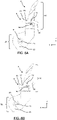
FIG. 8A is a cross-sectional view of the right front lever with the actuator in the engaged position. -
FIG. 8B is a cross-sectional view of the right front lever with the actuator in the disengaged position. -
FIG. 9 is a cross-sectional view of the computing unit with the right front lever with the actuator in the disengaged position. -
FIG. 10 is a schematic diagram of a method for accessing a secondary component from the internal body of the computing unit. - Reference will now be made in detail to specific embodiments or features, examples of which are illustrated in the accompanying drawings. Wherever possible, corresponding or similar reference numbers will be used throughout the drawings to refer to the same or corresponding parts. Moreover, references to various elements described herein are made collectively or individually when there may be more than one element of the same type. However, such references are merely exemplary in nature. It may be noted that any reference to elements in the singular may also be construed to relate to the plural and vice-versa without limiting the scope of the disclosure to the exact number or type of such elements unless set forth explicitly in the appended claims.
- A datacenter comprises several high-performance computing cabinets, called HPC cabinets or "clusters", arranged in rows within the datacenter and configured to house computing units, such as servers, switches and routers, to organize, process and store data. A HPC cabinet is configured to accommodate multiple server units, switches, cords and cables, rails, cable management bars, routers, path panels, and blanking panels.
- High performance computing has gained importance in recent years by several industries which are trending towards increasing sizes or combinations of two or more servers to achieve faster processing performance for a large number of processing operations. Solutions known to address such requirement of the industries include Ultra Path Interconnect (UPI) technology which provides a scalable multiprocessor system, for example, by linking motherboards of two or more computing units together.
- As illustrated in
Figure 1 , aHPC cabinet 100 comprises twovertical side walls 101, delimiting a central cavity with a front opening, so as to define vertically stacked sockets S having a standard height (U).Several computing units 1 are housed in theHPC cabinet 100 and mounted onto the twovertical side walls 101. In this example, the height of eachcomputing device 1 is 2U but could be different. - Each
vertical side wall 101 comprises a front portion which is configured to cooperate with an abutment wall of acomputing unit 1. In this example, the front portion of eachside wall 101 comprises threadedopenings 102. Such anHPC cabinet 100 is known from the prior art and won't be further detailed. - A
computing unit 1 according to the invention will be now presented. In this embodiment, as represented inFigures 2 ,3 and 4 , thecomputing unit 1 comprises aninternal body 3 mounted within anexternal body 2, theinternal body 3 being releasably coupled to theexternal body 2 in order to allow extraction of theinternal body 3 when theexternal body 2 is fixedly secured to theHPC cabinet 100. - As illustrated in
Figures 2 to 4 , thecomputing unit 1 is presented in the (X, Y, Z) referential in which the X axis extends longitudinally from the front to the rear, the Y axis extends laterally from the right to the left and the Z axis extends vertically from the bottom to the top. - According to the invention, the
external body 2 compriselateral walls 22, a bottom wall 23 (SeeFigure 4 ) and atop wall 21 defining together a housing (thetop wall 21 is not represented in thefigures 3 and 4 ). As represented infigures 3 and 4 , theexternal body 2 defines a front housing H1 where theinternal body 3 can be mounted and a back housing H2 where primary electronic components C1 are located, for example, at least one mother board and components secured to the mother board such as processors, Dual In-Line Memory Module (DIMM), etc. Theinternal body 3 is configured to be releasably coupled to the primary electronic components C1 from the back housing H2. Theexternal body 2 comprises at least a first connector K1 connected to the primary electronic components C1. The first connector K1 is located at the interface between the first housing H1 and the second housing H2. - As represented in
Figures 4 et 5 , eachlateral wall 22 of theexternal body 2 comprises anabutment wall 4 configured to be connected to theHPC cabinet 100. Eachabutment wall 4 is located in a front end of theexternal body 2. - The
abutment wall 4 from the right side will be now described in reference toFigure 5 . The description of the left side is similar and won't be presented in details. Theabutment wall 4 extends laterally to the right from theside wall 22. Theabutment wall 4 extends vertically in a YZ plane as represented inFigure 5 , preferably along the entire height of thecomputing unit 1. - The
abutment wall 4 comprises a lockingmember 41, preferably, a captive screw. Theabutment wall 4 is configured to abut to avertical side wall 101 of theHPC cabinet 100 which comprises several threadedopenings 102 in order to retain the lockingmember 41. In other words, thanks to theabutment wall 4, theexternal body 2 can be secured fixedly to theHPC cabinet 100 as in the prior art. - The
external body 2 comprises also a latchingwall 5 extending in front of theabutment wall 4. Preferably, the latchingwall 5 and theabutment wall 4 are longitudinally spaced apart from a distance L, defined along the X axis, which is comprised between 14 and 22 mm, preferably 18 mm. The latchingwall 5 is parallel to theabutment wall 4 and extends preferably along the entire height of thecomputing unit 1. In this example, the latchingwall 5 and theabutment wall 4 are fixed relatively to each other. - The latching
wall 5 comprises atrough opening 51, preferably a cutout or a notch, which is aligned longitudinally, along the X axis, with the lockingmember 41 from theabutment wall 4. A user can therefore access the lockingmember 41 from the front, for example with a screwdriver, in order to secure theexternal body 2 to theHPC cabinet 100. Thanks to the invention, this operation is performed only during the first mounting or for heavy maintenance. - The latching
wall 5 also comprises areception element 52, located on the back face of the latchingwall 5, configured to cooperate with afront lever 8 according to the invention. In this example, thereception element 52 is located at the periphery of thetrough opening 51. Thereception element 52 is preferably located directly over the throughopening 51. Thereception element 52 defines a recess in the back face of the latchingwall 5 so that a part of thefront lever 8 can be securely located in the recess when theinternal body 3 and theexternal body 2 are coupled together. - As represented in
Figure 5 , theexternal body 2 comprises also a throughopening 230 located on each side of thebottom wall 23 of theexternal body 2 so that eachfront lever 8 can latch with theexternal body 2 according to two latching points. The cooperation of theinternal body 3 with theexternal body 2 is very stable even with the releasable coupling. - As represented in
Figure 4 , theinternal body 3 comprises abottom wall 31 andside walls 32. Theinternal body 3 further comprises a motherboard connected to several secondary electronic components C2. In this example, theinternal body 3 comprises for example, processors, Dual In-Line Memory Module (DIMM), a PCIe component (GPU, FPGAs)), fans. - The
internal body 3 comprises at least a second connector K2 connected to the secondary electronic components C2; the second connector K2 being configured to cooperate with the first connector K1 when theinternal body 2 is coupled with the external body 3 (SeeFigure 3 ). The second connector K2 is located at the rear end of theinternal body 3. - In this embodiment, as represented in
Figure 4 , thecomputing unit 1 comprises, at each side of theinternal body 3, afront lever 8 pivotally coupled to theinternal body 3 and configured to latch: - with the corresponding latching
wall 5 of theexternal body 2 and - with the corresponding through opening 230 from the
bottom wall 23 in order to releasably couple theinternal body 3 with theexternal body 2. - The
internal body 3 comprises twofront levers 8 capable of being pivotably deflected by a user to allow detachment of theinternal body 3 from theexternal body 2. Likewise, thefront levers 8 also enable the user to push theinternal body 3 back into theexternal body 2. Thefront levers 8 eliminate use of any external tools to couple and uncouple theinternal body 3. Thefront lever 8 from the right side will be now described. The description of the left side is similar and won't be presented in details. - The
front lever 8 is coupled at the front end of theinternal body 3 and is pivotable along a lateral axis Y so that thefront lever 8 can be moved from the rear to the front and reciprocally. As it will be presented later, the rear position corresponds to an uncoupling position (Figure 6A ) whereas the front position corresponds to a coupling position (Figures 6B and 6C ). - A
front lever 8 is represented schematically inFigure 7 . Thefront lever 8 has a longitudinal shape and comprise abottom arm 8A with a pivot joint 81, anintermediate arm 8B and atop arm 8C with anactuator 9 for cooperating with the latchingwall 5 of theexternal body 2. - In this example, as represented in
figures 7 ,8A and 8B , thebottom arm 8A and thetop arm 8C are vertical and laterally offset along the Y axis because of theintermediate arm 8B which extends in the lateral direction. The lateral offset allows thefront lever 8 to latch with theexternal body 2 according to two latching points which are laterally offset for a better cooperation. Moreover, the horizontal portion ofintermediate arm 8B can be used as a handle to better extract theinternal body 3 from theexternal body 2. Thebottom arm 8A is closer to the center of theinternal body 3 than thetop arm 8C. - As shown in
Figure 7 , thebottom arm 8A comprises the pivot joint 81 and anantifriction material 82 which is preferably added to thebottom arm 8A around the pivot joint 81 in order to avoids friction during rotation of thefront lever 8 along a lateral Y1 axis (Figures 8A and 8B ). Thebottom arm 8A comprises at least one latchingtooth 83 for cooperating with thetrough opening 230 of thebottom wall 23 of theexternal body 2 presented before. Thanks to the rotation of thefront lever 8, the latchingtooth 83 can grab the periphery of thetrough opening 230 to pull theinternal body 3 within theexternal body 2. Thefront lever 8 provides a lift effect which decreases the user hardship. - The top end of the
top arm 8C is configured to be manipulated manually by a user without tools. The user can pull thefront lever 8 to the front or push thelever 8 to the rear. The top end may be ergonomically designed to allow easy access and manipulation by the user. - As represented in
Figure 8A and 8B , thetop arm 8C of thefront lever 8 comprises anactuator 9 which is configured to be inserted within the through opening 51 (Figure 9 ) of the latchingwall 5 in order to be retained by thereception element 52 which defines a recess in the back face of the latchingwall 5. Theactuator 9 is configured to allow disengagement of thefront lever 8 upon actuation. - As represented in
Figure 8A and 8B , theactuator 9 is pivotally mounted onto thetop arm 8C along a lateral axis Y2. Theactuator 9 comprises afirst end 91 for cooperating with thereception element 52 and asecond end 92 configured to be manipulated manually by a user without tools so that to modify the inclination of theactuator 9. In this example, theactuator 9 can pivot between an upward position (which corresponds to an engaged position - seefigure 8A ) and a downward position (which corresponds to a disengaged position - seefigure 8B ). - The
first end 91 has a shape of a tooth followed by arecess 93. In the engaged position, thereception element 52 of the latchingwall 5 is located in therecess 93 of theactuator 9 and thefront lever 8 cannot move. In the downward position, thereception element 52 of the latchingwall 5 is located in the throughopening 51 away from the reception element 52 (Seefigure 9 ). - In order to secure the engaged position, the
lever 8 comprises at least one biasingmember 94 configure to maintain theactuator 9 in the engaged position. In this embodiment, a spring is embedded within thetop arm 8C to maintain theactuator 9 in the upward position. - The front tooth (first end 91) of the
actuator 9 has an inclined wall which allows by "corner effect" to move theactuator 9 in the disengaged position against the spring pressure when thefront lever 8 is rotated towards the front (in the coupling position). The inclined wall of the front tooth cooperates with the inner periphery of the throughopening 51, more precisely with thereception element 52, to exert a downward pressure. When therecess 93 is aligned with thereception element 52, the biasingmember 94 moves theactuator 9 in the engaged position. In other words, when the user wants to couple theinternal body 3 with theexternal body 2, the user only requires to rotate thelever 8 towards the front to allow latching, theactuator 9 being automatically moved in the disengaged position and then in the engaged position. The ease of use will be presented for coupling/uncoupling theinternal body 3 with theexternal body 2. - It will now be described a method for accessing a second electronic component C2 from the
internal body 3, which is faulty. According toFigure 10 , in the initial position E0, theinternal body 3 is located in the housing H1 from the external body 2 (seefigure 3 ) and thefront lever 8 is latched with the latchingwall 5 and with thebottom wall 23 of the external body 3 (seeFigure 6B ). Theactuator 9 extends in the throughopening 51 and itsrecess 93 cooperates with thereception element 52. - As illustrated in
Figure 9 , the user manipulates E1 theactuator 9 from eachfront lever 8 in order to disengage eachactuator 9 from thereception element 52 of the latchingwall 5. Eachfront lever 8 is therefore free to rotate to the front. The user can then pivot E2 thefront lever 8 to unlatch the latchingwall 5 and thebottom wall 23 of theexternal body 2. Then, the user can pull E3 theinternal body 3 out from the housing H1 of theexternal body 2 in order to access the second electronic component C2 from theinternal body 3. Preferably, the user pulls thefront levers 8 in order to pull out theinternal body 3. The maintenance can be carried out without wasting time. - Advantageously, the
actuators 9 and thefront levers 8 can be manipulated by a user simultaneously with his two hands. In other words, the user can disengage theactuators 9, rotate thefront levers 8 and pull thefront levers 8 very practically. - In order to put back the
internal body 3 within theexternal body 2, the user pushes theinternal body 3 within theexternal body 2, preferably, with the help of thefront levers 8. The user can then pivot thefront levers 8 to latch automatically the latchingwall 5 and thebottom wall 23 of theexternal body 2. The latchingtooth 83 of thefront levers 8 allows to progressively tighten theinternal body 3 within theexternal body 2 so that the coupling is very stable. The automatic engagement of theactuator 9 forbids any accidental uncoupling. Thanks to the invention, thecomputing unit 1 is securely fixed to theHPC cabinet 100 after maintenance. - All terminologies used herein are for purposes of describing embodiments and examples and should not be construed as limiting the invention. As used herein, the singular forms "a," "an," and "the" are intended to include the plural forms as well, unless the context clearly indicates otherwise. Furthermore, to the extent that the terms "including," "includes," "having," "has," "with," or variants thereof, are used in either the detailed description and/or the claims, such terms are intended to be inclusive in a manner similar to the term "comprising."
- Unless otherwise defined, all terms (including technical and scientific terms) used herein have the same meaning as commonly understood by the person skilled in the art to which this present disclosure belongs. Furthermore, terms, such as those defined in commonly used dictionaries, should be interpreted as having a meaning that is consistent with their meaning in the context of the relevant art and will not be interpreted in an idealized or overly formal sense unless expressly defined herein.
- While aspects of the present disclosure have been particularly shown and described with reference to the embodiments above, it will be understood by those skilled in the art that various additional embodiments may be contemplated by the modification of the disclosed methods without departing from the spirit and scope of what is disclosed. Such embodiments should be understood to fall within the scope of the present disclosure as determined based upon the claims and any equivalents thereof.
Claims (11)
- A computing unit (1) configured to be mounted in a High-Performance Computing cabinet (100), thereafter HPC cabinet (100), defining a plurality of vertically stacked sockets (S), the computing unit (1) comprising:• an external body (2), comprising primary electronic components (C1), configured to engage with at least one of the sockets (S), the external body (2) comprising at least a bottom wall (23) and two lateral walls (22) defining a housing (H1) opened from the front, each lateral side (22) comprising an abutment wall (4) configured to be secured directly to the HPC cabinet (100) and a latching wall (5) located in front of the abutment wall (4), the external body (2) comprising at least a first connector (K1) connected to the primary electronic components (C1),• an internal body (3), comprising secondary electronic components (C2), the internal body (3) being releasably coupled with the external body (2) in order to allow extraction of the internal body (3) when the external body (2) is secured fixedly to the HPC cabinet (100), the internal body (3) comprising at least a second connector (K2) connected to the secondary electronic components (C2), the second connector (K2) being configured to cooperate with the first connector (K1) when the internal body (3) is coupled with the external body (2),• at least one front lever (8) pivotally coupled to the internal body (3) and configured to latch with a latching wall (5) of the external body (2) and to latch with the bottom wall (23) of the external body (2) in order to releasably couple the internal body (3) with the external body (2) when the internal body (3) is located within the housing (H1) of the external body (2).
- A computing unit according to claim 1, wherein the latching wall (5) comprises at least a reception element (52), located on the back face of the latching wall (5), configured to cooperate with the front lever (8).
- A computing unit according to claim 2, wherein the latching wall (5) comprises at least one through opening (51), preferably a notch, said reception element (52) being located at the periphery of the through opening (51) of the latching wall (5).
- A computing unit according to claim 3, wherein the abutment wall (4) comprises at least a locking member (41) accessible from the front of the computing unit (1) through the through opening (51).
- A computing unit according to any of claims 1 to 4, wherein the front lever (8) comprises at least an actuator (9) comprising a first end (91) for cooperating with the latching wall (5) and a second end (92) configured to be manipulated manually by a user without tools so that to modify the inclination of the actuator (9), the actuator (9) being pivotable between an engaged position for securing the internal body (3) to the external body (2) and a disengaged position.
- A computing unit according to claim 5, wherein the front lever (8) comprises at least a biasing member (94) configured to retain the actuator (9) in the engaged position.
- A computing unit according to claim 6, wherein the bottom wall (23) comprises at least a through opening (230) and the front lever (8) comprises at least a latching tooth (83) configured to cooperate with the through opening (230) in order to push the internal body (3) within the external body (2) when rotating the front lever (8) to the rear.
- A computing unit according to any of claims 1 to 7, wherein the front lever (8) comprises a bottom arm (8A) configured to latch with the bottom wall (23) and a top arm (8C) configured to latch with the latching wall (5) of the external body (2).
- A computing unit according to claim 8, wherein the bottom arm (8A) and the top arm (8C) of the front lever (8) are laterally offset.
- A computing unit according to any of claims 1 to 9, wherein the computing unit (1) comprises two front levers (8), one at each side of the internal body (3).
- A method for accessing a second electronic component (C2) from the internal body (3) of a computing unit (2) according to any of claims 1 to 10, the internal body (2) being located in the housing (H1) of the external body (3), the front lever (8) being latched with the latching wall (5) of the external body (2), the method comprising:• Pivoting (E2) the front lever (8) to unlatch the external body (2) and• Pulling (E3) the internal body (3) out from the housing (H1) of the external body (2) in order to access the second electronic component (C2) from the internal body (3).
Priority Applications (2)
| Application Number | Priority Date | Filing Date | Title |
|---|---|---|---|
| EP21170707.0A EP4084589B1 (en) | 2021-04-27 | 2021-04-27 | Computing unit for a hpc cabinet and method for accessing an electronic component from the computing unit |
| US17/720,738 US11770912B2 (en) | 2021-04-27 | 2022-04-14 | Computing unit for a HPC cabinet and a method for accessing an electronic component from the computing unit |
Applications Claiming Priority (1)
| Application Number | Priority Date | Filing Date | Title |
|---|---|---|---|
| EP21170707.0A EP4084589B1 (en) | 2021-04-27 | 2021-04-27 | Computing unit for a hpc cabinet and method for accessing an electronic component from the computing unit |
Publications (2)
| Publication Number | Publication Date |
|---|---|
| EP4084589A1 true EP4084589A1 (en) | 2022-11-02 |
| EP4084589B1 EP4084589B1 (en) | 2024-02-07 |
Family
ID=75728573
Family Applications (1)
| Application Number | Title | Priority Date | Filing Date |
|---|---|---|---|
| EP21170707.0A Active EP4084589B1 (en) | 2021-04-27 | 2021-04-27 | Computing unit for a hpc cabinet and method for accessing an electronic component from the computing unit |
Country Status (2)
| Country | Link |
|---|---|
| US (1) | US11770912B2 (en) |
| EP (1) | EP4084589B1 (en) |
Families Citing this family (1)
| Publication number | Priority date | Publication date | Assignee | Title |
|---|---|---|---|---|
| US12621950B2 (en) * | 2023-07-25 | 2026-05-05 | Quanta Computer Inc. | Lockable computing device with movable lever |
Citations (3)
| Publication number | Priority date | Publication date | Assignee | Title |
|---|---|---|---|---|
| US20020090851A1 (en) * | 2001-01-09 | 2002-07-11 | Wrycraft Sean Conor | Ejector mechanism |
| US20070149018A1 (en) * | 2005-12-23 | 2007-06-28 | Schroff Gmbh | Circuit board with lever-latch handle |
| US20070258224A1 (en) * | 2006-05-04 | 2007-11-08 | Adlink Technology Inc. | Atca locking lever mounting structure |
Family Cites Families (8)
| Publication number | Priority date | Publication date | Assignee | Title |
|---|---|---|---|---|
| US4632588A (en) * | 1985-02-13 | 1986-12-30 | Northern Telecom Limited | Latching lever for printed circuit boards |
| US6058579A (en) * | 1999-03-29 | 2000-05-09 | International Business Machines Corporation | Snap latch insertion/removal lever |
| US6579029B1 (en) * | 2000-08-23 | 2003-06-17 | Rockwell Collins, Inc. | Multi-function latch device for a module unit |
| EP1499171B1 (en) * | 2003-07-18 | 2006-06-07 | Schroff GmbH | Device for inserting, extracting a plug-in unit in a bay |
| US20060134953A1 (en) * | 2004-12-22 | 2006-06-22 | Adaptec, Inc. | Electronic module latching mechanism |
| CN102692972B (en) * | 2011-03-23 | 2016-08-10 | 西安瑞阳电子科技有限公司 | Bracket and there is the computer equipment of this bracket |
| CN102736698B (en) * | 2011-04-02 | 2017-02-15 | 鸿富锦精密工业(深圳)有限公司 | Cabinet |
| US11197389B2 (en) * | 2020-04-06 | 2021-12-07 | Super Micro Computer Inc. | Server chassis |
-
2021
- 2021-04-27 EP EP21170707.0A patent/EP4084589B1/en active Active
-
2022
- 2022-04-14 US US17/720,738 patent/US11770912B2/en active Active
Patent Citations (3)
| Publication number | Priority date | Publication date | Assignee | Title |
|---|---|---|---|---|
| US20020090851A1 (en) * | 2001-01-09 | 2002-07-11 | Wrycraft Sean Conor | Ejector mechanism |
| US20070149018A1 (en) * | 2005-12-23 | 2007-06-28 | Schroff Gmbh | Circuit board with lever-latch handle |
| US20070258224A1 (en) * | 2006-05-04 | 2007-11-08 | Adlink Technology Inc. | Atca locking lever mounting structure |
Also Published As
| Publication number | Publication date |
|---|---|
| US11770912B2 (en) | 2023-09-26 |
| EP4084589B1 (en) | 2024-02-07 |
| US20220346262A1 (en) | 2022-10-27 |
Similar Documents
| Publication | Publication Date | Title |
|---|---|---|
| US10321597B2 (en) | User interface enhanced storage sled handle with embedded security features | |
| US20060134953A1 (en) | Electronic module latching mechanism | |
| US12439537B2 (en) | Information handling system rack release latch having vertical movement in a latched state | |
| US8331085B2 (en) | Electronic device | |
| US11770912B2 (en) | Computing unit for a HPC cabinet and a method for accessing an electronic component from the computing unit | |
| US7576977B2 (en) | Shoulder screw and handle drive mounting system | |
| US12108555B2 (en) | Interconnecting module configured for interconnecting computing units in a HPC cabinet and a method for engaging said interconnecting module | |
| US12484168B2 (en) | Server system server cover latch system | |
| US11507149B2 (en) | Apparatuses for expansion device retention | |
| US11877420B2 (en) | HPC computing unit comprising a top tray comprising secondary electronic components | |
| US7251130B2 (en) | Computer system with vertically offset hard disk drives | |
| US20220248543A1 (en) | Connecting module for a computing resource | |
| US11672095B2 (en) | Expansion module for a computing unit for a high-performance computer cabinet and a method for the tool-less replacement of an expansion card of an expansion module | |
| US10757829B2 (en) | Modular server | |
| US11956916B2 (en) | Computing unit for a HPC cabinet and a method for accessing an electronic component of the computing unit | |
| US11672098B2 (en) | Electronic device configured to be mounted in a cluster housing and comprising a front tray for mounting at least one expansion card | |
| US12213273B2 (en) | Server information handling system with power supply unit handle alignment component | |
| US20250287521A1 (en) | Locking device and locking structure using same | |
| US20260040479A1 (en) | Interconnecting module configured for interconnecting computing units in a hpc cabinet and a method for engaging said interconnecting module | |
| US20150277514A1 (en) | Card retention mechanism | |
| CN120712788A (en) | Equipment locking device | |
| US11467997B2 (en) | Hot-swappable protocol expander module for storage array | |
| TWI923188B (en) | Component module and computer device using the same | |
| US20260025937A1 (en) | Server Information Handling System Peripheral Riser Module System | |
| US11910556B1 (en) | Fastener with gear usage for tray install and eject |
Legal Events
| Date | Code | Title | Description |
|---|---|---|---|
| PUAI | Public reference made under article 153(3) epc to a published international application that has entered the european phase |
Free format text: ORIGINAL CODE: 0009012 |
|
| STAA | Information on the status of an ep patent application or granted ep patent |
Free format text: STATUS: THE APPLICATION HAS BEEN PUBLISHED |
|
| AK | Designated contracting states |
Kind code of ref document: A1 Designated state(s): AL AT BE BG CH CY CZ DE DK EE ES FI FR GB GR HR HU IE IS IT LI LT LU LV MC MK MT NL NO PL PT RO RS SE SI SK SM TR |
|
| STAA | Information on the status of an ep patent application or granted ep patent |
Free format text: STATUS: REQUEST FOR EXAMINATION WAS MADE |
|
| RBV | Designated contracting states (corrected) |
Designated state(s): AL AT BE BG CH CY CZ DE DK EE ES FI FR GB GR HR HU IE IS IT LI LT LU LV MC MK MT NL NO PL PT RO RS SE SI SK SM TR |
|
| 17P | Request for examination filed |
Effective date: 20221126 |
|
| RAP1 | Party data changed (applicant data changed or rights of an application transferred) |
Owner name: BULL SAS |
|
| GRAP | Despatch of communication of intention to grant a patent |
Free format text: ORIGINAL CODE: EPIDOSNIGR1 |
|
| STAA | Information on the status of an ep patent application or granted ep patent |
Free format text: STATUS: GRANT OF PATENT IS INTENDED |
|
| RIC1 | Information provided on ipc code assigned before grant |
Ipc: H05K 7/14 20060101AFI20230320BHEP |
|
| INTG | Intention to grant announced |
Effective date: 20230406 |
|
| P01 | Opt-out of the competence of the unified patent court (upc) registered |
Effective date: 20230330 |
|
| GRAJ | Information related to disapproval of communication of intention to grant by the applicant or resumption of examination proceedings by the epo deleted |
Free format text: ORIGINAL CODE: EPIDOSDIGR1 |
|
| STAA | Information on the status of an ep patent application or granted ep patent |
Free format text: STATUS: REQUEST FOR EXAMINATION WAS MADE |
|
| GRAP | Despatch of communication of intention to grant a patent |
Free format text: ORIGINAL CODE: EPIDOSNIGR1 |
|
| STAA | Information on the status of an ep patent application or granted ep patent |
Free format text: STATUS: GRANT OF PATENT IS INTENDED |
|
| INTC | Intention to grant announced (deleted) | ||
| INTG | Intention to grant announced |
Effective date: 20230821 |
|
| GRAS | Grant fee paid |
Free format text: ORIGINAL CODE: EPIDOSNIGR3 |
|
| GRAA | (expected) grant |
Free format text: ORIGINAL CODE: 0009210 |
|
| STAA | Information on the status of an ep patent application or granted ep patent |
Free format text: STATUS: THE PATENT HAS BEEN GRANTED |
|
| AK | Designated contracting states |
Kind code of ref document: B1 Designated state(s): AL AT BE BG CH CY CZ DE DK EE ES FI FR GB GR HR HU IE IS IT LI LT LU LV MC MK MT NL NO PL PT RO RS SE SI SK SM TR |
|
| REG | Reference to a national code |
Ref country code: GB Ref legal event code: FG4D |
|
| REG | Reference to a national code |
Ref country code: CH Ref legal event code: EP |
|
| REG | Reference to a national code |
Ref country code: IE Ref legal event code: FG4D |
|
| REG | Reference to a national code |
Ref country code: DE Ref legal event code: R096 Ref document number: 602021009142 Country of ref document: DE |
|
| REG | Reference to a national code |
Ref country code: LT Ref legal event code: MG9D |
|
| REG | Reference to a national code |
Ref country code: NL Ref legal event code: MP Effective date: 20240207 |
|
| PG25 | Lapsed in a contracting state [announced via postgrant information from national office to epo] |
Ref country code: IS Free format text: LAPSE BECAUSE OF FAILURE TO SUBMIT A TRANSLATION OF THE DESCRIPTION OR TO PAY THE FEE WITHIN THE PRESCRIBED TIME-LIMIT Effective date: 20240607 |
|
| PG25 | Lapsed in a contracting state [announced via postgrant information from national office to epo] |
Ref country code: LT Free format text: LAPSE BECAUSE OF FAILURE TO SUBMIT A TRANSLATION OF THE DESCRIPTION OR TO PAY THE FEE WITHIN THE PRESCRIBED TIME-LIMIT Effective date: 20240207 |
|
| PG25 | Lapsed in a contracting state [announced via postgrant information from national office to epo] |
Ref country code: GR Free format text: LAPSE BECAUSE OF FAILURE TO SUBMIT A TRANSLATION OF THE DESCRIPTION OR TO PAY THE FEE WITHIN THE PRESCRIBED TIME-LIMIT Effective date: 20240508 |
|
| REG | Reference to a national code |
Ref country code: AT Ref legal event code: MK05 Ref document number: 1656172 Country of ref document: AT Kind code of ref document: T Effective date: 20240207 |
|
| PG25 | Lapsed in a contracting state [announced via postgrant information from national office to epo] |
Ref country code: HR Free format text: LAPSE BECAUSE OF FAILURE TO SUBMIT A TRANSLATION OF THE DESCRIPTION OR TO PAY THE FEE WITHIN THE PRESCRIBED TIME-LIMIT Effective date: 20240207 Ref country code: NL Free format text: LAPSE BECAUSE OF FAILURE TO SUBMIT A TRANSLATION OF THE DESCRIPTION OR TO PAY THE FEE WITHIN THE PRESCRIBED TIME-LIMIT Effective date: 20240207 Ref country code: RS Free format text: LAPSE BECAUSE OF FAILURE TO SUBMIT A TRANSLATION OF THE DESCRIPTION OR TO PAY THE FEE WITHIN THE PRESCRIBED TIME-LIMIT Effective date: 20240507 |
|
| PG25 | Lapsed in a contracting state [announced via postgrant information from national office to epo] |
Ref country code: ES Free format text: LAPSE BECAUSE OF FAILURE TO SUBMIT A TRANSLATION OF THE DESCRIPTION OR TO PAY THE FEE WITHIN THE PRESCRIBED TIME-LIMIT Effective date: 20240207 |
|
| PG25 | Lapsed in a contracting state [announced via postgrant information from national office to epo] |
Ref country code: AT Free format text: LAPSE BECAUSE OF FAILURE TO SUBMIT A TRANSLATION OF THE DESCRIPTION OR TO PAY THE FEE WITHIN THE PRESCRIBED TIME-LIMIT Effective date: 20240207 |
|
| PG25 | Lapsed in a contracting state [announced via postgrant information from national office to epo] |
Ref country code: RS Free format text: LAPSE BECAUSE OF FAILURE TO SUBMIT A TRANSLATION OF THE DESCRIPTION OR TO PAY THE FEE WITHIN THE PRESCRIBED TIME-LIMIT Effective date: 20240507 Ref country code: NO Free format text: LAPSE BECAUSE OF FAILURE TO SUBMIT A TRANSLATION OF THE DESCRIPTION OR TO PAY THE FEE WITHIN THE PRESCRIBED TIME-LIMIT Effective date: 20240507 Ref country code: NL Free format text: LAPSE BECAUSE OF FAILURE TO SUBMIT A TRANSLATION OF THE DESCRIPTION OR TO PAY THE FEE WITHIN THE PRESCRIBED TIME-LIMIT Effective date: 20240207 Ref country code: LT Free format text: LAPSE BECAUSE OF FAILURE TO SUBMIT A TRANSLATION OF THE DESCRIPTION OR TO PAY THE FEE WITHIN THE PRESCRIBED TIME-LIMIT Effective date: 20240207 Ref country code: IS Free format text: LAPSE BECAUSE OF FAILURE TO SUBMIT A TRANSLATION OF THE DESCRIPTION OR TO PAY THE FEE WITHIN THE PRESCRIBED TIME-LIMIT Effective date: 20240607 Ref country code: HR Free format text: LAPSE BECAUSE OF FAILURE TO SUBMIT A TRANSLATION OF THE DESCRIPTION OR TO PAY THE FEE WITHIN THE PRESCRIBED TIME-LIMIT Effective date: 20240207 Ref country code: GR Free format text: LAPSE BECAUSE OF FAILURE TO SUBMIT A TRANSLATION OF THE DESCRIPTION OR TO PAY THE FEE WITHIN THE PRESCRIBED TIME-LIMIT Effective date: 20240508 Ref country code: FI Free format text: LAPSE BECAUSE OF FAILURE TO SUBMIT A TRANSLATION OF THE DESCRIPTION OR TO PAY THE FEE WITHIN THE PRESCRIBED TIME-LIMIT Effective date: 20240207 Ref country code: ES Free format text: LAPSE BECAUSE OF FAILURE TO SUBMIT A TRANSLATION OF THE DESCRIPTION OR TO PAY THE FEE WITHIN THE PRESCRIBED TIME-LIMIT Effective date: 20240207 Ref country code: BG Free format text: LAPSE BECAUSE OF FAILURE TO SUBMIT A TRANSLATION OF THE DESCRIPTION OR TO PAY THE FEE WITHIN THE PRESCRIBED TIME-LIMIT Effective date: 20240207 Ref country code: AT Free format text: LAPSE BECAUSE OF FAILURE TO SUBMIT A TRANSLATION OF THE DESCRIPTION OR TO PAY THE FEE WITHIN THE PRESCRIBED TIME-LIMIT Effective date: 20240207 |
|
| PG25 | Lapsed in a contracting state [announced via postgrant information from national office to epo] |
Ref country code: PL Free format text: LAPSE BECAUSE OF FAILURE TO SUBMIT A TRANSLATION OF THE DESCRIPTION OR TO PAY THE FEE WITHIN THE PRESCRIBED TIME-LIMIT Effective date: 20240207 Ref country code: PT Free format text: LAPSE BECAUSE OF FAILURE TO SUBMIT A TRANSLATION OF THE DESCRIPTION OR TO PAY THE FEE WITHIN THE PRESCRIBED TIME-LIMIT Effective date: 20240607 |
|
| PG25 | Lapsed in a contracting state [announced via postgrant information from national office to epo] |
Ref country code: SE Free format text: LAPSE BECAUSE OF FAILURE TO SUBMIT A TRANSLATION OF THE DESCRIPTION OR TO PAY THE FEE WITHIN THE PRESCRIBED TIME-LIMIT Effective date: 20240207 Ref country code: PT Free format text: LAPSE BECAUSE OF FAILURE TO SUBMIT A TRANSLATION OF THE DESCRIPTION OR TO PAY THE FEE WITHIN THE PRESCRIBED TIME-LIMIT Effective date: 20240607 Ref country code: PL Free format text: LAPSE BECAUSE OF FAILURE TO SUBMIT A TRANSLATION OF THE DESCRIPTION OR TO PAY THE FEE WITHIN THE PRESCRIBED TIME-LIMIT Effective date: 20240207 Ref country code: LV Free format text: LAPSE BECAUSE OF FAILURE TO SUBMIT A TRANSLATION OF THE DESCRIPTION OR TO PAY THE FEE WITHIN THE PRESCRIBED TIME-LIMIT Effective date: 20240207 |
|
| PG25 | Lapsed in a contracting state [announced via postgrant information from national office to epo] |
Ref country code: DK Free format text: LAPSE BECAUSE OF FAILURE TO SUBMIT A TRANSLATION OF THE DESCRIPTION OR TO PAY THE FEE WITHIN THE PRESCRIBED TIME-LIMIT Effective date: 20240207 |
|
| PG25 | Lapsed in a contracting state [announced via postgrant information from national office to epo] |
Ref country code: SM Free format text: LAPSE BECAUSE OF FAILURE TO SUBMIT A TRANSLATION OF THE DESCRIPTION OR TO PAY THE FEE WITHIN THE PRESCRIBED TIME-LIMIT Effective date: 20240207 |
|
| PG25 | Lapsed in a contracting state [announced via postgrant information from national office to epo] |
Ref country code: CZ Free format text: LAPSE BECAUSE OF FAILURE TO SUBMIT A TRANSLATION OF THE DESCRIPTION OR TO PAY THE FEE WITHIN THE PRESCRIBED TIME-LIMIT Effective date: 20240207 Ref country code: EE Free format text: LAPSE BECAUSE OF FAILURE TO SUBMIT A TRANSLATION OF THE DESCRIPTION OR TO PAY THE FEE WITHIN THE PRESCRIBED TIME-LIMIT Effective date: 20240207 |
|
| PG25 | Lapsed in a contracting state [announced via postgrant information from national office to epo] |
Ref country code: SK Free format text: LAPSE BECAUSE OF FAILURE TO SUBMIT A TRANSLATION OF THE DESCRIPTION OR TO PAY THE FEE WITHIN THE PRESCRIBED TIME-LIMIT Effective date: 20240207 |
|
| PG25 | Lapsed in a contracting state [announced via postgrant information from national office to epo] |
Ref country code: SM Free format text: LAPSE BECAUSE OF FAILURE TO SUBMIT A TRANSLATION OF THE DESCRIPTION OR TO PAY THE FEE WITHIN THE PRESCRIBED TIME-LIMIT Effective date: 20240207 Ref country code: SK Free format text: LAPSE BECAUSE OF FAILURE TO SUBMIT A TRANSLATION OF THE DESCRIPTION OR TO PAY THE FEE WITHIN THE PRESCRIBED TIME-LIMIT Effective date: 20240207 Ref country code: RO Free format text: LAPSE BECAUSE OF FAILURE TO SUBMIT A TRANSLATION OF THE DESCRIPTION OR TO PAY THE FEE WITHIN THE PRESCRIBED TIME-LIMIT Effective date: 20240207 Ref country code: EE Free format text: LAPSE BECAUSE OF FAILURE TO SUBMIT A TRANSLATION OF THE DESCRIPTION OR TO PAY THE FEE WITHIN THE PRESCRIBED TIME-LIMIT Effective date: 20240207 Ref country code: DK Free format text: LAPSE BECAUSE OF FAILURE TO SUBMIT A TRANSLATION OF THE DESCRIPTION OR TO PAY THE FEE WITHIN THE PRESCRIBED TIME-LIMIT Effective date: 20240207 Ref country code: CZ Free format text: LAPSE BECAUSE OF FAILURE TO SUBMIT A TRANSLATION OF THE DESCRIPTION OR TO PAY THE FEE WITHIN THE PRESCRIBED TIME-LIMIT Effective date: 20240207 |
|
| REG | Reference to a national code |
Ref country code: DE Ref legal event code: R097 Ref document number: 602021009142 Country of ref document: DE |
|
| PG25 | Lapsed in a contracting state [announced via postgrant information from national office to epo] |
Ref country code: MC Free format text: LAPSE BECAUSE OF FAILURE TO SUBMIT A TRANSLATION OF THE DESCRIPTION OR TO PAY THE FEE WITHIN THE PRESCRIBED TIME-LIMIT Effective date: 20240207 |
|
| PG25 | Lapsed in a contracting state [announced via postgrant information from national office to epo] |
Ref country code: MC Free format text: LAPSE BECAUSE OF FAILURE TO SUBMIT A TRANSLATION OF THE DESCRIPTION OR TO PAY THE FEE WITHIN THE PRESCRIBED TIME-LIMIT Effective date: 20240207 |
|
| REG | Reference to a national code |
Ref country code: CH Ref legal event code: PL |
|
| PG25 | Lapsed in a contracting state [announced via postgrant information from national office to epo] |
Ref country code: IT Free format text: LAPSE BECAUSE OF FAILURE TO SUBMIT A TRANSLATION OF THE DESCRIPTION OR TO PAY THE FEE WITHIN THE PRESCRIBED TIME-LIMIT Effective date: 20240207 |
|
| PLBE | No opposition filed within time limit |
Free format text: ORIGINAL CODE: 0009261 |
|
| STAA | Information on the status of an ep patent application or granted ep patent |
Free format text: STATUS: NO OPPOSITION FILED WITHIN TIME LIMIT |
|
| PG25 | Lapsed in a contracting state [announced via postgrant information from national office to epo] |
Ref country code: LU Free format text: LAPSE BECAUSE OF NON-PAYMENT OF DUE FEES Effective date: 20240427 |
|
| REG | Reference to a national code |
Ref country code: BE Ref legal event code: MM Effective date: 20240430 |
|
| PG25 | Lapsed in a contracting state [announced via postgrant information from national office to epo] |
Ref country code: LU Free format text: LAPSE BECAUSE OF NON-PAYMENT OF DUE FEES Effective date: 20240427 Ref country code: IT Free format text: LAPSE BECAUSE OF FAILURE TO SUBMIT A TRANSLATION OF THE DESCRIPTION OR TO PAY THE FEE WITHIN THE PRESCRIBED TIME-LIMIT Effective date: 20240207 |
|
| 26N | No opposition filed |
Effective date: 20241108 |
|
| PG25 | Lapsed in a contracting state [announced via postgrant information from national office to epo] |
Ref country code: BE Free format text: LAPSE BECAUSE OF NON-PAYMENT OF DUE FEES Effective date: 20240430 |
|
| PG25 | Lapsed in a contracting state [announced via postgrant information from national office to epo] |
Ref country code: BE Free format text: LAPSE BECAUSE OF NON-PAYMENT OF DUE FEES Effective date: 20240430 Ref country code: CH Free format text: LAPSE BECAUSE OF NON-PAYMENT OF DUE FEES Effective date: 20240430 |
|
| PG25 | Lapsed in a contracting state [announced via postgrant information from national office to epo] |
Ref country code: IE Free format text: LAPSE BECAUSE OF NON-PAYMENT OF DUE FEES Effective date: 20240427 |
|
| PG25 | Lapsed in a contracting state [announced via postgrant information from national office to epo] |
Ref country code: SI Free format text: LAPSE BECAUSE OF FAILURE TO SUBMIT A TRANSLATION OF THE DESCRIPTION OR TO PAY THE FEE WITHIN THE PRESCRIBED TIME-LIMIT Effective date: 20240207 |
|
| PGFP | Annual fee paid to national office [announced via postgrant information from national office to epo] |
Ref country code: DE Payment date: 20250417 Year of fee payment: 5 |
|
| PGFP | Annual fee paid to national office [announced via postgrant information from national office to epo] |
Ref country code: FR Payment date: 20250422 Year of fee payment: 5 |
|
| PG25 | Lapsed in a contracting state [announced via postgrant information from national office to epo] |
Ref country code: CY Free format text: LAPSE BECAUSE OF FAILURE TO SUBMIT A TRANSLATION OF THE DESCRIPTION OR TO PAY THE FEE WITHIN THE PRESCRIBED TIME-LIMIT; INVALID AB INITIO Effective date: 20210427 |
|
| PG25 | Lapsed in a contracting state [announced via postgrant information from national office to epo] |
Ref country code: HU Free format text: LAPSE BECAUSE OF FAILURE TO SUBMIT A TRANSLATION OF THE DESCRIPTION OR TO PAY THE FEE WITHIN THE PRESCRIBED TIME-LIMIT; INVALID AB INITIO Effective date: 20210427 |
|
| PGFP | Annual fee paid to national office [announced via postgrant information from national office to epo] |
Ref country code: GB Payment date: 20260324 Year of fee payment: 6 |