EP4084388A2 - Verfahren und vorrichtung zur pdcch-wiederholung in einem multi-trp-system und priorisierung von coresets - Google Patents
Verfahren und vorrichtung zur pdcch-wiederholung in einem multi-trp-system und priorisierung von coresets Download PDFInfo
- Publication number
- EP4084388A2 EP4084388A2 EP22163557.6A EP22163557A EP4084388A2 EP 4084388 A2 EP4084388 A2 EP 4084388A2 EP 22163557 A EP22163557 A EP 22163557A EP 4084388 A2 EP4084388 A2 EP 4084388A2
- Authority
- EP
- European Patent Office
- Prior art keywords
- coreset
- pdcch
- coresets
- mos
- candidates
- Prior art date
- Legal status (The legal status is an assumption and is not a legal conclusion. Google has not performed a legal analysis and makes no representation as to the accuracy of the status listed.)
- Pending
Links
Images


Classifications
-
- H—ELECTRICITY
- H04—ELECTRIC COMMUNICATION TECHNIQUE
- H04W—WIRELESS COMMUNICATION NETWORKS
- H04W24/00—Supervisory, monitoring or testing arrangements
- H04W24/08—Testing, supervising or monitoring using real traffic
-
- H—ELECTRICITY
- H04—ELECTRIC COMMUNICATION TECHNIQUE
- H04W—WIRELESS COMMUNICATION NETWORKS
- H04W72/00—Local resource management
- H04W72/20—Control channels or signalling for resource management
- H04W72/23—Control channels or signalling for resource management in the downlink direction of a wireless link, i.e. towards a terminal
- H04W72/231—Control channels or signalling for resource management in the downlink direction of a wireless link, i.e. towards a terminal the control data signalling from the layers above the physical layer, e.g. RRC or MAC-CE signalling
-
- H—ELECTRICITY
- H04—ELECTRIC COMMUNICATION TECHNIQUE
- H04B—TRANSMISSION
- H04B7/00—Radio transmission systems, i.e. using radiation field
- H04B7/02—Diversity systems; Multi-antenna system, i.e. transmission or reception using multiple antennas
- H04B7/022—Site diversity; Macro-diversity
- H04B7/024—Co-operative use of antennas of several sites, e.g. in co-ordinated multipoint or co-operative multiple-input multiple-output [MIMO] systems
-
- H—ELECTRICITY
- H04—ELECTRIC COMMUNICATION TECHNIQUE
- H04B—TRANSMISSION
- H04B7/00—Radio transmission systems, i.e. using radiation field
- H04B7/02—Diversity systems; Multi-antenna system, i.e. transmission or reception using multiple antennas
- H04B7/04—Diversity systems; Multi-antenna system, i.e. transmission or reception using multiple antennas using two or more spaced independent antennas
- H04B7/0413—MIMO systems
-
- H—ELECTRICITY
- H04—ELECTRIC COMMUNICATION TECHNIQUE
- H04L—TRANSMISSION OF DIGITAL INFORMATION, e.g. TELEGRAPHIC COMMUNICATION
- H04L5/00—Arrangements affording multiple use of the transmission path
- H04L5/0001—Arrangements for dividing the transmission path
- H04L5/0003—Two-dimensional division
- H04L5/0005—Time-frequency
- H04L5/0007—Time-frequency the frequencies being orthogonal, e.g. OFDM(A) or DMT
- H04L5/001—Time-frequency the frequencies being orthogonal, e.g. OFDM(A) or DMT the frequencies being arranged in component carriers
-
- H—ELECTRICITY
- H04—ELECTRIC COMMUNICATION TECHNIQUE
- H04L—TRANSMISSION OF DIGITAL INFORMATION, e.g. TELEGRAPHIC COMMUNICATION
- H04L5/00—Arrangements affording multiple use of the transmission path
- H04L5/003—Arrangements for allocating sub-channels of the transmission path
- H04L5/0032—Distributed allocation, i.e. involving a plurality of allocating devices, each making partial allocation
- H04L5/0035—Resource allocation in a cooperative multipoint environment
-
- H—ELECTRICITY
- H04—ELECTRIC COMMUNICATION TECHNIQUE
- H04L—TRANSMISSION OF DIGITAL INFORMATION, e.g. TELEGRAPHIC COMMUNICATION
- H04L5/00—Arrangements affording multiple use of the transmission path
- H04L5/003—Arrangements for allocating sub-channels of the transmission path
- H04L5/0053—Allocation of signalling, i.e. of overhead other than pilot signals
-
- H—ELECTRICITY
- H04—ELECTRIC COMMUNICATION TECHNIQUE
- H04W—WIRELESS COMMUNICATION NETWORKS
- H04W72/00—Local resource management
- H04W72/04—Wireless resource allocation
- H04W72/044—Wireless resource allocation based on the type of the allocated resource
- H04W72/0446—Resources in time domain, e.g. slots or frames
-
- H—ELECTRICITY
- H04—ELECTRIC COMMUNICATION TECHNIQUE
- H04W—WIRELESS COMMUNICATION NETWORKS
- H04W72/00—Local resource management
- H04W72/04—Wireless resource allocation
- H04W72/044—Wireless resource allocation based on the type of the allocated resource
- H04W72/0453—Resources in frequency domain, e.g. a carrier in FDMA
-
- H—ELECTRICITY
- H04—ELECTRIC COMMUNICATION TECHNIQUE
- H04W—WIRELESS COMMUNICATION NETWORKS
- H04W72/00—Local resource management
- H04W72/20—Control channels or signalling for resource management
- H04W72/23—Control channels or signalling for resource management in the downlink direction of a wireless link, i.e. towards a terminal
-
- H—ELECTRICITY
- H04—ELECTRIC COMMUNICATION TECHNIQUE
- H04W—WIRELESS COMMUNICATION NETWORKS
- H04W72/00—Local resource management
- H04W72/50—Allocation or scheduling criteria for wireless resources
- H04W72/51—Allocation or scheduling criteria for wireless resources based on terminal or device properties
-
- H—ELECTRICITY
- H04—ELECTRIC COMMUNICATION TECHNIQUE
- H04W—WIRELESS COMMUNICATION NETWORKS
- H04W8/00—Network data management
- H04W8/22—Processing or transfer of terminal data, e.g. status or physical capabilities
-
- H—ELECTRICITY
- H04—ELECTRIC COMMUNICATION TECHNIQUE
- H04L—TRANSMISSION OF DIGITAL INFORMATION, e.g. TELEGRAPHIC COMMUNICATION
- H04L5/00—Arrangements affording multiple use of the transmission path
- H04L5/0001—Arrangements for dividing the transmission path
- H04L5/0014—Three-dimensional division
- H04L5/0023—Time-frequency-space
Definitions
- the present disclosure relates generally to multiple-input multiple-output (MIMO) transmission schemes, and more particularly, to transmission schemes for physical downlink control channel (PDCCH) transmission from multiple transmission and reception points (TRPs) to schedule a same channel.
- MIMO multiple-input multiple-output
- PDCCH physical downlink control channel
- TRPs transmission and reception points
- MIMO transmission schemes have been widely used in digital communication to increase the capacity of wireless channels.
- the 3 rd Generation Partnership Project (3GPP) mobile communication standard supports MIMO transmission schemes in which a PDSCH or physical uplink shared channel (PUSCH) is transmitted from different physical antennas or different antenna ports.
- 3GPP 3 rd Generation Partnership Project
- Different antenna ports of a MIMO transmission scheme may be within a single TRP, in which case the scheme is referred to as a single TRP transmission scheme.
- Different antenna ports of one or different channels may also be within multiple TRPs, which are typically non-co-located, in which case the scheme is referred to as a multi-TRP (M-TRP) scheme.
- M-TRP multi-TRP
- An example of the M-TRP scheme includes a rank-2 PDSCH transmitted by two antenna ports, where a first antenna port is within a first TRP and a second antenna port is within a second TRP.
- M-TRP transmissions can be categorized into single-downlink control information (DCI)-TRP and multi-DCI M-TRP.
- DCI downlink control information
- M-TRP multi-DCI M-TRP.
- a single PDCCH is transmitted from one of the TRPs and schedules one or more PDSCHs.
- different layers of a single PDSCH are transmitted from different TRPs.
- multiple PDSCHs (multiplexed in a time domain or a frequency domain) with the same transport block (TB) are transmitted, where all layers of a single PDSCH are transmitted from a respective one of the TRPs.
- Different PDSCHs may be transmitted from different TRPs according to a pattern.
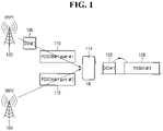
- FIG. 1 is a diagram illustrating a single-DCI M-TRP transmission scheme.
- a single DCI (PDCCH) 106 is transmitted to a user equipment (UE) 114 from a first TRP 102, and schedules a PDSCH 108 with two layers.
- a first layer 110 of the PDSCH is transmitted from a first antenna port within the first TRP 102, while a second layer 112 is transmitted from a second antenna port within a second TRP 104.
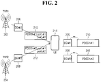
- each TRP transmits its own PDCCH, which schedules a PDSCH that is also transmitted from the ports within the same TRP.
- FIG. 2 is a diagram illustrating multi-DCI M-TRP transmission.
- Each DCI schedules one PDSCH with two-layer transmission, a first PDSCH 210 and a second PDSCH 212. All of the layers of a given PDSCH are transmitted from the antenna ports within the same TRP.
- TDM time division multiplexing
- FDM frequency division multiplexing
- SDM special division multiplexing
- SFN single frequency network
- one encoding/rate matching is for a PDCCH with two transmission configuration indicator (TCI) states.
- TCI transmission configuration indicator
- a single PDCCH candidate has two different TCI states.
- specific control channel elements (CCEs)/resource element groups (REGs) of a candidate may be associated with a first TCI state and the remainder of the CCEs/REGs may be associated with a second TCI state.
- CCEs control channel elements
- REGs resource element groups
- encoding/rate matching is based on one repetition, and the same coded bits are repeated for another repetition.
- Each repetition has the same number of CCEs and coded bits, and corresponds to the same DCI payload.
- separate DCIs schedule the same physical downlink shared channel (PDSCH)/physical uplink shared channel (PUSCH)/reference signal (RS)/transport block (TB)/etc., or result in the same outcome.
- PDSCH physical downlink shared channel
- PUSCH physical uplink shared channel
- RS reference signal
- TB transport block
- a method for monitoring PDCCH candidates by a UE.
- a reference control resource set (CORESET) having a plurality of TCI states is identified.
- the PDCCH candidates in the reference CORESET and in one or more CORESETs that overlap the reference CORESET in a time domain, are monitored.
- Each of the one or more CORESETs has a set of one or more TCI states that is either identical to, or a subset of, the plurality of TCI states of the reference CORESET.
- the monitored PDCCH candidates are received in accordance with an SFN transmission scheme.
- a UE includes a processor and a non-transitory computer readable storage medium storing instructions. When executed, the instructions cause the processor to identify a reference CORESET having a plurality of TCI states, and monitor PDCCH candidates in the reference CORESET and in one or more CORESETs that overlap the reference CORESET in a time domain. Each of the one or more CORESETs has a set of one or more TCI states that is either identical to, or a subset of, the plurality of TCI states of the reference CORESET.
- the monitored PDCCHs are received in accordance with an SFN transmission scheme.
- a method for monitoring PDCCH candidates by a UE.
- MOs of the first SS set and the second SS set are arranged in ascending order based on the set maximum number of MOs.
- the PDCCH candidates in the arranged MOs are received in accordance with the UE and the network communicating using a multi-TRP repetition scheme or a multi-TRP multi-chance scheme.
- a UE includes a processor and a non-transitory computer readable storage medium storing instructions.
- the instructions When executed, the instructions cause the processor to set a maximum number of MOs of a first SS set permitted between a first MO of the first SS set and a second MO of a second SS set.
- First PDCCH candidates of the first MO are linked to second PDDCH candidates of the second MO.
- the instructions also cause the processor to arrange MOs of the first SS set and the second SS set in ascending order based on the set maximum number of MOs.
- the PDCCH candidates in the arranged MOs are received in accordance with the UE and the network communicating using a multi-TRP repetition scheme or a multi-TRP multi-chance scheme.
- first, second, etc. may be used for describing various elements, the structural elements are not restricted by the terms. The terms are only used to distinguish one element from another element. For example, without departing from the scope of the present disclosure, a first structural element may be referred to as a second structural element. Similarly, the second structural element may also be referred to as the first structural element. As used herein, the term "and/or" includes any and all combinations of one or more associated items.
- the electronic device may be one of various types of electronic devices.
- the electronic devices may include, for example, a portable communication device (e.g., a smart phone), a computer, a portable multimedia device, a portable medical device, a camera, a wearable device, or a home appliance.
- a portable communication device e.g., a smart phone
- a computer e.g., a laptop, a desktop, a tablet, or a portable multimedia device
- portable medical device e.g., a portable medical device
- camera e.g., a camera
- a wearable device e.g., a smart bracelet
- terms such as “1 st ,” “2nd,” “first,” and “second” may be used to distinguish a corresponding component from another component, but are not intended to limit the components in other aspects (e.g., importance or order). It is intended that if an element (e.g., a first element) is referred to, with or without the term “operatively” or “communicatively”, as “coupled with,” “coupled to,” “connected with,” or “connected to” another element (e.g., a second element), it indicates that the element may be coupled with the other element directly (e.g., wired), wirelessly, or via a third element.
- module may include a unit implemented in hardware, software, or firmware, and may interchangeably be used with other terms, such as, for example, "logic,” “logic block,” “part,” and “circuitry.”
- a module may be a single integral component, or a minimum unit or part thereof, adapted to perform one or more functions.
- a module may be implemented in a form of an application-specific integrated circuit (ASIC).
- ASIC application-specific integrated circuit
- the present disclosure defines a new PDCCH prioritization rule that enables the UE to monitor overlapping PDCCHs with different TCI states.
- the present disclosure also provides restrictions on an SS configuration to address log-likelihood ratio (LLR) buffering, and blind decoding (BD)/CCE counting for inter-span repetitions.
- LLR log-likelihood ratio
- BD blind decoding
- the PDCCH prioritization rule is essential for efficient PDCCH monitoring in M-TRP systems with increased reliability of PDCCH, which is mainly due to beam diversity. Without such a prioritization rule, UE behavior is either undefined or the UE unnecessarily drops the overlapping PDCCH candidates with different TCI states.
- the prioritization rule assumes a capability at the UE side to monitor two different TCI states at the same time.
- the SS configuration restrictions allow the UE to maintain a low LLR buffer size for PDCCH monitoring per slot.
- a BD/CCE counting rule for inter-span PDCCH monitoring allows per-span SS dropping.
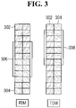
- FIG. 3 is a diagram illustrating PDCCHs according to the 1SS-1CORESET scheme, according to an embodiment.
- Blocks 302 correspond to REGs/CCEs associated with a first TCI state
- blocks 304 correspond to REGs/CCEs associated with a second TCI state.
- a first PDCCH (with DCI) 306 includes REGs/CCEs that are split evenly between the first and second TCI states.
- a second PDCCH (with DCI) 308 also includes REGs/CCEs that are split evenly between the first and second TCI states.
- a DCI or PDCCH candidate in a given SS set is associated with both TCI states of the CORESET.
- scheme B two sets of PDCCH candidates (in a given SS set) are associated with the two TCI states of the CORESET, respectively.
- scheme C two sets of PDCCH candidates are associated with two corresponding SS sets, where both SS sets are associated with the CORESET and each SS set is associated with only one TCI state of the CORESET.
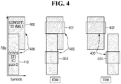
- FIG. 4 is a diagram illustrating PDCCHs according to the 1SS-2CORESET scheme, according to an embodiment.
- a first PDCCH 402 and a second PDCCH 404 of a single SS set 406 are shown in a first CORESET 408 and a second CORESET 410, respectively, for both FDM and TDM.
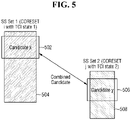
- FIG. 5 is a diagram illustrating PDCCHs according to the 2SS-2CORESET scheme, according to an embodiment. Specifically, a first PDCCH 502 (candidate x) is from a first SS set and a first COERSET 504 having a first TCI state, while a second PDCCH (candidate y) 506 is from a second SS and a second CORESET 508 having a second TCI state.
- embodiments of the disclosure generally relate to the 1SS-1CORESET scheme
- the described methods may be applied to any SS-CORESET multiplexing scheme.
- the following methods may also be applied to both repetition and multi-chance PDCCHs.
- a PDCCH candidate may be configured to be transmitted with two different TCI states, each corresponding to a specific TRP. In this case, the definition of the "same TCI state" needs to be clarified.
- the legacy rule is mainly suitable for when the CORESET/PDCCH candidates are configured with a single TCI state.
- CORESET #1 may be configured with a TCI state pair with QCL-typeD pair ( a 1 , b 1 ) and CORESET #2 may be configured with a TCI state pair with QCL-typeD pair ( a 2 , b 2 ) .
- specific rules are needed to determine if the two CORESETs can be categorized to have the same TCI states for the purpose of PDCCH prioritization.
- FIG. 6 is a diagram illustrating CORESETs, according to an embodiment.
- First and second PDCCHs 602 and 604 are in a first CORESET and a first SS set and associated with two different TCI states.
- a third PDCCH 606 is in a second CORESET and a second SS and a fourth PDDCH 608 is in a third CORESET and a third SS.
- the second and third CORESETs are explicitly linked.
- the UE should be able to receive all PDCCH candidates in all shown CORESETs.
- Multiple TCI states may be associated with a CORESET in the high-speed train (HST) and SFN transmission schemes.
- HHT high-speed train
- SFN PDCCH enhancement scheme a CORESET is associated with two different TCI states and a PDCCH is transmitted such that the demodulation reference signal (DMRS) ports are associated with the same two different TCI states.
- DMRS demodulation reference signal
- the association of a CORESET with two different TCI states may be indicated by a medium access control (MAC)-control element (CE) command.
- MAC medium access control
- CE control element
- the MAC-CE may activate a TCI codepoint with a single TCI state or multiple TCI states, which may be described as a single element, a pair, or m -tupple (e.g., m TCI states for one CORESET) by associating the TCI codepoints to a CORESET ID.
- m TCI states for one CORESET
- a given PDCCH is then associated with a TCI state pair with qcl-typeD pair ( a i , b i ) .
- a reference CORESET is chosen as the CORESET that corresponds to a common search space (CSS) set with a lowest index in a cell with a lowest index containing CSS, if any. Otherwise, the reference CORESET is chosen as the CORESET that corresponds to a UE-specific search space (USS) set with a lowest index in a cell with a lowest index.
- CSS common search space
- USS UE-specific search space
- a CORESET prioritization rule is provided for an SFN-based PDCCH and a reference CORESET with two TCI states. If the UE operates in a single cell or an intra-band CA, and is configured with multi-TRP SFN PDCCH, the UE applies the legacy rule to determine the CORESETs to monitor. In case that the reference CORESET is associated with two TCI states ( a , b ), the UE monitors all overlapping CORESETs associated with the same two states ( a , b ) .
- Simultaneous reception of two TCI states typically requires two antenna panels at the UE side, with a high likelihood that the two beams arrive at different panels. If the UE is capable of monitoring a CORESET with two different beams, it may also be capable of monitoring CORSETS with a single TCI state in any of the team beams.
- a CORESET prioritization rule is provided for an SFN-based PDCCH and a reference CORESET with two TCI states. If the UE operates in single cell or an intra-band CA, and is configured with multi-TRP SFN PDCCH, the UE applies the legacy rule to determine the CORESETs to monitor. In case that the reference CORESET is associated with two TCI states ( a, b ), the UE monitors all overlapping CORESETs associated with a single TCI state a , a single TCI state b , or a pair of TCI states ( a, b ).
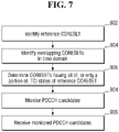
- FIG. 7 is a flowchart illustrating a method of monitoring PDCCH candidates, according to an embodiment.
- a reference CORESET is identified that has a plurality of TCI states.
- CORESETs that overlap the reference CORESET in the time domain are identified.
- one or more CORESETs having all of, or only a portion of, the plurality of TCI states of the reference CORESET are determined from the identified CORESETs. Specifically, each of the one or more determined CORESETs has a set of one or more TCI states that is either identical to, or a subset of, the plurality of TCI states of the reference CORESET.
- PDCCH candidates in the reference CORESET and in the one or more determined CORESETs are monitored.
- the monitored PDCCH candidates are received in accordance with an SFN transmission scheme.
- the reference CORESET may have a total of two TCI states, however, embodiments of the disclosure are not limited thereto.
- the UE may also monitor overlapping CORESETs with two different TCI states where one of the TCI states is the same as that of the reference CORESET.
- a CORESET prioritization rule is provided for SFN-based PDCCH and a reference CORESET with a single TCI state. If the UE operates in single cell or an intra-band CA and is configured with multi-TRP SFN PDCCH, the UE applies the legacy rule to determine the CORESETs to monitor. In case that the reference CORESET is associated with a single TCI state a , the UE determines a CORESET, among the overlapping CORESETs, with two different TCI states ( a, b ) or ( b, a ), such that at least one of the two TCI states is the same as that of the reference CORESET.
- the chosen CORESET corresponds to the CSS set with the lowest index in the cell with the lowest index containing CSS, if any. Otherwise, the chosen CORESET corresponds to the USS set with the lowest index in the cell with the lowest index.
- the UE monitors all overlapping CORESETs associated with the single TCI state a , the single TCI state b , or the pair of TCI states ( a, b ).
- a CORESET with two TCI states should be prioritized over a CORESET with a single TCI state, regardless of the SS type and the serving cell index, to ensure the reliability of PDCCH reception by ensuring its monitoring for the special purpose it has been configured (e.g., beam diversity in M-TRP schemes).
- a reference CORESET with two TCI states is prioritized. If the UE operates in a single cell or an intra-band CA and is configured with multi-TRP SFN PDCCH, the UE applies the legacy rule to determine the CORESETs to monitor. The UE determines the reference CORESET among CORESETs with two different TCI states.
- the reference CORESET corresponds to the CSS set with the lowest index in the cell with the lowest index containing CSS, if any. Otherwise, the reference CORESET corresponds to the USS set with the lowest index in the cell with lowest index.
- the PDCCH transmission may be also configured to be in an FDM scheme where a CORESET is configured with two different TCI states.
- a CORESET is configured with two different TCI states.
- one PDCCH candidate may be associated with two different TCI states, or there may be PDCCH candidates in the CORESET which are linked together such that the linked PDCCH candidates have different single TCI states.
- a CORESET is associated with two different TCI states ( a, b ). Any of the methods described above for the SFN PDCCH scheme can also be applied to the FDM case.
- the UE may declare a capability to receive two overlapping PDSCHs from the two TRPs, where the two PDSCHs are associated with different TCI states.
- This transmission scheme is typically scheduled by PDCCHs, which are transmitted from the same TRP as the PDSCHs.
- PDCCH association to the TRPs is based on a radio resource control (RRC) information element (IE) referred to CORESETPoolIndex , in the CORESET in which the PDCCH is transmitted.
- RRC radio resource control
- CORESETPoolIndex a radio resource control information element
- a UE with the aforementioned capability may also be capable of receiving/monitoring overlapping PDCCHs/CORESETs with different TCI states. Since the current CORESET prioritization rule in Rel-15/16 does not support simultaneous reception of those PDCCHs, an enhancement may be required.
- the simplest approach to define an enhancement is to resolve the PDCCH prioritization within a CORESETPoolIndex value.
- a CORESET prioritization rule is provided for M-DCI M-TRP, per CORESETPoolIndex. If the UE operates in a single cell or an intra-band CA and is configured with a multi-DCI M-TRP PDSCH transmission scheme on a serving cell and each CORESET is associated with the TRPs according to the value of an RRC IE CORESETPoolIndex , the UE monitors the PDCCHs by applying the legacy PDCCH prioritization rule to all CORESETs that have the same value of CORESETPoolIndex.
- the UE With two values of CORESETPoolIndex , the UE will determine a first set of PDCCHs in the first set of CORESETs with the first value, and a second set of PDCCHs in the second set of CORESETs with the second value. The UE monitors PDCCHs in both sets regardless of whether they overlap.
- the above-described fifth method runs two different versions of the legacy algorithm.
- the method then monitors all CORESETs in any of the sets.
- CORESETs are not typically associated with a TRP.
- the CORESETs on the M-DCI M-TRP cell may be of a higher priority and may need to be monitored always regardless of the SS type and serving cell index. Accordingly, the reference CORESET may be chosen from the CORESETs in the cell configured with M-DCI M-TRP.
- a different PDCCH scheme is when every PDCCH candidate of a CORESET is transmitted with two different TCI states in a TDM manner, and the CORESET is configured with two different TCI states with the corresponding ( a i ,b i ) .
- a CORESET prioritization rule for TDM PDCCH if the UE operates in single cell or intra-band CA and is configured with multi-TRP TDM PDCCH within one PDCCH candidate of the CORESET, the UE applies the legacy rule to determine the CORESETs to monitor with the following modification (a CORSET #i is configured with a TCI state pair with QCL-typeD pair).
- a CORESET#1 is considered to have the same QCL-typeD as CORESET #2 if for every OFDM symbol on which UE monitors both CORESETs the QCL-typeD values of the PDCCH candidates of the two CORESETs are the same.
- CORESET#1 is chosen as the first monitored CORESET
- a CORESET#2 is considered to have the same QCL-typeD as CORESET #1. This is because at every overlapping OFDM symbol, the QCL-typeD values of the PDCCH candidates of the two CORESETs are the same.
- FIG. 8 is a diagram illustrating PDCCH candidates of an SS set, according to an embodiment.
- First and second PDCCHs 802 and 804 are in a first CORESET and a first SS set.
- a third PDCCH 806 is in a second CORESET and a second SS set.
- a fourth PDCCH 808 is in a second COREST and a second SS set.
- PDCCH candidates of the second SS set are associated with the second CORESET such that a certain number of candidates are associated with the first QCL-typeD value of the CORESET and certain other candidates are associated with the second QCL-typeD value of the CORESET.
- the second CORESET may be considered to be partially monitored by the UE as certain candidates of the second CORESET do not overlap with those of the first CORESET with different QCL-typeD values.
- the following method is a conservative approach in which the UE does not monitor any candidates of the CORESET#2 in FIG. 8 , even though some may not experience a QCL-typeD collision.
- a seventh method with a CORESET prioritization rule for TDM PDCCH (linked PDDCH candidates)
- the UE if the UE operates in single cell or intra-band CA and is configured with multi-TRP TDM PDCCH, where the SS sets and the PDCCH candidates are linked together as repetition or multi-chance in a TDM scheme associated with the same CORESET, the UE applies the legacy rule to determine the CORESETs to monitor with the following modification (CORSET # i is configured with a TCI state pair with qcl-typeD pair).
- a CORESET#1 is considered to have the same QCL-typeD as CORESET #2 if for every OFDM symbol on which UE monitors both CORESETs the QCL-typeD values of the PDCCH candidates of the two CORESETs are the same.
- the above-described methods result in full dropping of a CORESET (SS) if any of its PDCCH candidates have a different QCL-typeD value on a symbol that overlaps with the first CORESET.
- Such schemes may unnecessarily drop the whole SS or CORESET even though the UE is capable of receiving some PDCCH candidates within them.
- the UE can monitor the PDCCH in the second set of candidates of CORESET#1. This line of behavior can be realized by partial dropping of CORESETs.
- an eighth method with a general CORESET prioritization rule (partial monitoring: PDCCH candidate granularity: time domain (TD) overlapping)
- the UE applies the legacy rule to determine the CORESETs to monitor with the following modification.
- the UE monitors PDCCH candidates in SS sets corresponding to the second CORESET if the PDCCH candidate of the second CORESET does not overlap in time with any PDCCH candidate of the first CORESET, such that the two candidates are associated with two different values QCL-typeD on the same symbol.
- the UE may still be able to monitor two different PDCCH candidates from the two CORESETs if the two candidates have the same QCL-typeD on the overlapping resource elements (REs).
- the following method defines UE behavior based on this approach.
- a ninth method with a general CORESET prioritization rule partial monitoring: PDCCH candidate granularity: TD and frequency domain (FD) overlapping
- the UE applies the legacy rule to determine the CORESETs to monitor with the following modification.
- the UE monitors PDCCH candidates in SS sets corresponding to the second CORESET if the PDCCH candidate of the second CORESET does not overlap with any PDCCH candidate of the first CORESET in both time and frequency domain, such that the two candidates are associated with two different values of QCL-typeD on same REs.
- the eighth and ninth methods describe PDCCH monitoring in the second CORESET on a PDCCH candidate level (i.e., the UE may monitor some PDCCH candidates in the second COREST and not monitor some others). Monitoring may also be defined on a CORESTE level, as described in the methods below.
- CORESET level granularity: TD overlapping if the UE operates in single cell or intra-band CA and is configured with any of the multi-TRP PDCCH schemes, the UE applies the legacy rule to determine the CORESETs to monitor with the following modification.
- the UE monitors PDCCH candidates in SS sets corresponding to the second CORESET if for every two PDCCH candidate #1 from the first CORESET and PDCCH candidate #2 from the second CORESET, the two candidates do not overlap in time with two different values of QCL-typeD on the same symbols.
- the UE In an eleventh method with a general CORESET prioritization rule (CORESET level granularity: TD and FD overlapping), if the UE operates in single cell or intra-band CA and is configured with any of the multi-TRP PDCCH schemes, the UE applies the legacy rule to determine the CORESETs to monitor with the following modification.
- CORESET level granularity: TD and FD overlapping if the UE operates in single cell or intra-band CA and is configured with any of the multi-TRP PDCCH schemes, the UE applies the legacy rule to determine the CORESETs to monitor with the following modification.
- the UE monitors PDCCH candidates in SS sets corresponding to the second CORESET if for every two PDCCH candidate #1 from the first CORESET and PDCCH candidate #2 from the second CORESET, the two candidates do not overlap in both time or frequency with two different values of QCL-typeD on the same REs.
- one of the options for non SFN M-TRP PDCCH transmission is repetition, as described below.
- Encoding/rate matching is based on one repetition, and the same coded bits are repeated for the other repetition.
- Each repetition has the same number of CCEs and coded bits, and corresponds to the same DCI payload.
- a soft combining operation may happen at a UE to handle such repetitions.
- Such soft combining would need to be done in a candidate-by-candidate manner, while acknowledging linkage between repetitions for every decoding attempt.
- Such candidate-by-candidate combining also implies that a UE needs to hold full LLR buffer of two separate SSs until decoding of all candidates is done. Hence, careful consideration would be necessary with option 2 to reduce implementation impact. For example, the number of BDs/CCEs corresponding to repetitions may need to be limited.
- an additional limitation on BD/CCE for SSs and CORESETs corresponding to the repetitions may need to be considered.
- the amount of such limitation as well as necessity of such limitation may need to be declared by a UE as a UE capability. Since many BD candidates can exist in overlapping manner in each SS, an LLR buffer in terms of candidates typically becomes much larger than an LLR buffer in terms of CCE. Hence, a UE may need to store an LLR of a first repetition in terms of CCE, which implies that shuffling of LLR and restructuring buffer in terms of candidates would need to happen for both first and second repetition LLRs when soft combining is attempted.
- a situation in which a UE needs to hold an LLR buffer of first repetitions for long time, while a UE also needs to monitor other MOs including more of such first repetitions should be prevented.
- the amount of the worst case memory corresponding to unresolved first repetitions and the current MO would be two times of per-slot BD/CCE limit, and such amount would further increase with larger distance between slots.
- SSs corresponding to such repetitions may need to be contained within one slot or within certain distance in time.
- Distance between SSs corresponding to such repetitions can be declared as UE capability.
- support of inter-slot repetition can be declared as UE capability.
- per-FSPC/per-FS/per-BC capability signaling for this functionality which are described below.
- a UE is not required to store more than per-slot BD/CCE limit at any given time.
- UE capability signaling described in 5G new radio (NR) specification 38.306 and 38.822 refers to the mechanism with which the UE informs the gNB of its capability to perform certain features.
- the following is a (non-limiting) list of possible ways of reporting UE capability.
- the UE can report its capability to perform certain features in any scenario. In this case, it is said that the UE reports its capability on a per-UE basis.
- the UE can report its capability to perform certain features in particular bands. In this case, it is said that the UE reports its capability on a per-band basis.
- the UE can report its capability to perform certain features in particular band combinations for CA. In this case, it is said that the UE reports its capability on a per-bandcombination or per-BC basis.
- the UE can report its capability to perform certain features in specific band(s) in particular band combination for CA.
- a mechanism referred to as feature sets can be used to allow for such flexibility in reporting, and it is said that the UE reports its capability on a per-featureSet or per-FS basis in that case.
- the UE can report its capability to perform certain features in specific component carrier(s) (CC) in particular band combination for CA.
- CC component carrier
- a mechanism referred to as feature sets per cc can be used to allow for such flexibility in reporting, and it is said that the UE reports its capability on a per-featureSet per cc or per-FSPC basis in that case.
- band combination is collection of bands to represent CA configuration as described in 3GPP specification 38.101.
- a UE's flexibility for declaring support of certain features increase. For example, if feature A and feature B are per-FSPC, a UE can have full flexibility of supporting only one of feature A and B in each CC. However, if those features are per-UE, then a UE would always need to support or not support. Trade-off to added flexibility is its overhead in signaling. Hence, the determination of how certain feature is declared must acknowledge complexity of the feature in UE implementation and associated signaling overhead.
- the first and second SS sets each include L MOs in the slots, where the PDCCH candidates of i -th MO of the first SS set are linked to the PDCCH candidates of the i -th MO of the second SS set.
- the L MOs of the first and second SS set are such that:
- the number of MOs of the first SS set which are between the i -th MO of the first SS set and i -th MO of the second SS set is less than or equal to M , where M is either fixed or RRC configured according to a UE capability.
- a special case of first method is when the maximum number is equal to zero, which means that the two sets of MOs are fully intermixed.
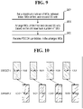
- FIG. 9 is a flowchart illustrating a method of monitoring PDCCH candidates, according to an embodiment.
- a maximum number of MOs of a first SS set permitted between a first MO of the first SS set and a second MO of a second SS set is set. The maximum number is set according to a capability of the UE.
- First PDCCH candidates of the first MO are linked to second PDCCH candidates of the second MO. Specifically each MO of the first SS set is linked to a respective MO of the second SS set. Additionally, a time between individual MOs in a linked pair of MOs is less than or equal to a preset time.
- MOs of the first SS set and the second SS set are arranged in ascending order based on the set maximum number of MOs.
- the ascending order is based on a start symbol or an end symbol of each of the MOs.
- the PDCCH candidates in the arranged MOs are received in accordance with the UE and a network communicating using a multi-TRP repetition scheme or a multi-TRP multi-chance scheme.
- the first and second SS sets each include L MOs in the slots, where the PDCCH candidates of i -th MO of the first SS set are linked to the PDCCH candidates of the i -th MO of the second SS set.
- the L MOs of the first and second SS set are such that:
- none of MOs of the first SS set is between i -th MO of the first SS set and i -th MO of the second SS set.
- FIG. 10 is a diagram illustrating two sets of MOs fully inter-mixed, according to an embodiment.
- First through fourth MOs 1002-1008 are of a first CORESET and SS set.
- Fifth through eighth MOs 1010-1016 are of a second CORESET and SS set.
- There is at most M 0 MOs for the first SS set, shown in red, between any two linked MOs one from the first SS set and one from the second SS set.
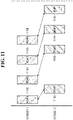
- FIG. 11 is a diagram illustrating two sets of MOs fully inter-mixed, according to another embodiment.
- Reference numerals 1102-1116 generally correspond to 1002-1016 and the corresponding description above with respect to FIG. 10 .
- MO number 2 There is one MO of the first SS set which appears between the two MOs linked MOs (i.e., MO number 2).
- the aforementioned methods may not be sufficient to mitigate the LLR buffering issue.
- One other aspect which may impact the issue, is the number of close/overlapping linked MOs.
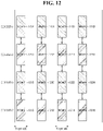
- FIG. 12 is a diagram illustrating overlapping linked MOs, according to an embodiment.
- Reference numerals 1202-1216 generally correspond to 1002-1016 and the corresponding description above with respect to FIG. 10 .
- Ninth through twelfth MOs 1218-1214 are in a third CORESET.
- the UE would need to buffer LLRs for the four "first-repetition" MOs, which increases the buffering requirement significantly, even though the configuration satisfies the conditions in the second method, which is the most mitigating case.
- the maximum number of first-repetition MOs can be limited within any X symbols. Note that an MO is referred to as "first"-repetition MO if it is linked to another MO which starts later in time. In this case, the linked MO which starts later is referred to as "second-repetition" MO.
- the maximum number of "first-repetition" MOs which are within an interval of X symbols is less than or equal to K , where K is either fixed or determined according to a UE capability.
- "First-repetition" MOs may include unlinked MOs (i.e., MOs not including linked candidates).
- the interval of X symbols may be the PDCCH monitoring span, or any consecutive X symbols in the slot.
- the upper bound K may only be applied when the "first-repetition" and the "second-repetition" are not within the same set of X symbols.
- the maximum number of "first-repetition" MOs that are within a span, a slot, or a set of slots, which are linked to MOs that are in the next spans or slots is less than or equal to K , where K is either fixed or determined according to a UE capability.
- the upper bound K may only be applied when the "first-repetition" and the "second-repetition" are not within the same set of X symbols.
- Another problematic scenario is when all the conditions provided by the aforementioned methods are satisfied, but the second-repetition MO is too close to a first-repetition MO which appears later in time.
- FIG. 13 is a diagram illustrating a second-repetition MO and a first repetition MO later in time, according to an embodiment.
- the UE may not have sufficient time to finish processing of the two linked first MOs 1302 and 1304 before starting to monitor the linked second MOs 1306 and 1308. Therefore, it would need additional buffer for storing the LLRs of the second MO as the buffer of first MO may be still occupied.
- one approach is to introduce a minimum gap between second-repetition MO and a first-repetition MO which comes later in time.
- a fifth method with a minimum time gap between unlink first-repetition and second repetitions when the UE is configured with intra-slot PDCCH repetition, and assuming ordering the MOs of the linked SS sets in ascending order of the start or end symbol of the MO, if a second-repetition MO #i of SS set 1 is linked to a second-repetition MO #i of SS set 2, the time gap from the end of the second-repetition to the start of the next first-repetition MO is at least K symbols, where K is either fixed number or determined according to the UE capability.
- a PDCCH candidate that is linked to a later candidate is "unresolved" until the linked candidate is not transmitted. This is due to the fact that the UE may need to store LLRs of the first repetition and process them jointly after reception of the second candidate. Similarly MOs can be considered as resolved or unresolved. Whether an MO is resolved or unresolved is a function of time.
- a sixth method with an unresolved PDCCH candidate or MO when the UE is configured with PDCCH repetition, a first set of candidates are transmitted in the first MO, and a second set of candidates are transmitted in the second MO, which ends/starts later than the first MO, the first MO is unresolved at a given time, if the second MO doesn't end by that time.
- Unresolved MOs/candidates may include unlinked MOs/candidates (i.e., MOs not including linked candidates).
- a maximum number of unresolved MOs/candidates at a given time, or BD/CCE limits corresponding to unresolved candidates/MOs may be limited to maintain UE complexity.
- the maximum number of unresolved MOs at any check-point time is less than or equal to an upper limit.
- the check-point time may be arbitrary, a slot boundary, or a span boundary.
- a slot/span boundary check point there may be a limitation of the maximum number of MOs that are unresolved across slots/spans. In other words, there may be a limitation on a maximum number of MOs corresponding to a first repetition, where corresponding second repetitions are in a different slot/span.
- the seventh method may be described in terms of unresolved MOs.
- the number of unresolved MOs at the end of each X symbols is less than or equal to K.
- the unresolved BD/CCE limit at any check-point time is less than or equal to an upper limit.
- the check-point time may be arbitrary, a slot boundary, or a span boundary.
- a slot/span boundary check point there may be a limitation of a maximum number of BD/CCE unresolved across slots/spans. In other words, there may be a limitation of a maximum number of BD/CCE corresponding to a first repetition, where corresponding second repetitions are in a different slot/span.
- each PDCCH candidate can be associated to two TCI states, it may be needed to count a candidate more than once towards the BD/CCE limit.
- an FDM scheme requires simultaneous reception of two different TCI states, which may increase the PDCCH monitoring complexity.
- soft combining may be used for polar decoding.
- RE de-mapping to combine the LLRs may also increase the PDCCH monitoring complexity.
- each PDCCH may be counted separately regardless of repetition of the content of the DCI. Overall, PDCCH candidate counting should be revisited to account for multiple TCI states.
- the UE When the UE is configured with inter-span or inter-slot PDCCH repetition, it must be specified how to count the linked PDCCH candidates across the spans or slots.
- the UE may report ⁇ 1 , ⁇ 2 separately as a UE capability.
- the UE counts the candidates in the first span or slot according to ⁇ 1 and ⁇ 2 , and performs SS overbooking or dropping in the span/slot..
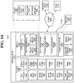
- FIG. 14 is a block diagram of an electronic device in a network environment, according to one embodiment.
- an electronic device 1401 in a network environment 1400 may communicate with an electronic device 1402 via a first network 1498 (e.g., a short-range wireless communication network), or an electronic device 1404 or a server 1408 via a second network 1499 (e.g., a long-range wireless communication network).
- the electronic device 1401 may communicate with the electronic device 1404 via the server 1408.
- the electronic device 1401 may include a processor 1420, a memory 1430, an input device 1450, a sound output device 1455, a display device 1460, an audio module 1470, a sensor module 1476, an interface 1477, a haptic module 1479, a camera module 1480, a power management module 1488, a battery 1489, a communication module 1490, a subscriber identification module (SIM) 1496, or an antenna module 1497.
- at least one (e.g., the display device 1460 or the camera module 1480) of the components may be omitted from the electronic device 1401, or one or more other components may be added to the electronic device 1401.
- Some of the components may be implemented as a single integrated circuit (IC).
- the sensor module 1476 e.g., a fingerprint sensor, an iris sensor, or an illuminance sensor
- the display device 1460 e.g., a display.
- the processor 1420 may execute, for example, software (e.g., a program 1440) to control at least one other component (e.g., a hardware or a software component) of the electronic device 1401 coupled with the processor 1420, and may perform various data processing or computations. As at least part of the data processing or computations, the processor 1420 may load a command or data received from another component (e.g., the sensor module 1476 or the communication module 1490) in volatile memory 1432, process the command or the data stored in the volatile memory 1432, and store resulting data in non-volatile memory 1434.
- software e.g., a program 1440
- the processor 1420 may load a command or data received from another component (e.g., the sensor module 1476 or the communication module 1490) in volatile memory 1432, process the command or the data stored in the volatile memory 1432, and store resulting data in non-volatile memory 1434.
- the processor 1420 may include a main processor 1421 (e.g., a central processing unit (CPU) or an application processor (AP)), and an auxiliary processor 1423 (e.g., a graphics processing unit (GPU), an image signal processor (ISP), a sensor hub processor, or a communication processor (CP)) that is operable independently from, or in conjunction with, the main processor 1421. Additionally or alternatively, the auxiliary processor 1423 may be adapted to consume less power than the main processor 1421, or execute a particular function. The auxiliary processor 1423 may be implemented as being separate from, or a part of, the main processor 1421.
- auxiliary processor 1423 e.g., a graphics processing unit (GPU), an image signal processor (ISP), a sensor hub processor, or a communication processor (CP)
- the auxiliary processor 1423 may be adapted to consume less power than the main processor 1421, or execute a particular function.
- the auxiliary processor 1423 may be implemented as being separate from, or a part of, the
- the auxiliary processor 1423 may control at least some of the functions or states related to at least one component (e.g., the display device 1460, the sensor module 1476, or the communication module 1490) among the components of the electronic device 1401, instead of the main processor 1421 while the main processor 1421 is in an inactive (e.g., sleep) state, or together with the main processor 1421 while the main processor 1421 is in an active state (e.g., executing an application).
- the auxiliary processor 1423 e.g., an image signal processor or a communication processor
- the memory 1430 may store various data used by at least one component (e.g. , the processor 1420 or the sensor module 1476) of the electronic device 1401.
- the various data may include, for example, software (e.g., the program 1440) and input data or output data for a command related thereto.
- the memory 1430 may include the volatile memory 1432 or the non-volatile memory 1434.
- the program 1440 may be stored in the memory 1430 as software, and may include, for example, an operating system (OS) 1442, middleware 1444, or an application 1446.
- OS operating system
- middleware middleware
- application application
- the input device 1450 may receive a command or data to be used by other component (e.g., the processor 1420) of the electronic device 1401, from the outside (e.g., a user) of the electronic device 1401.
- the input device 1450 may include, for example, a microphone, a mouse, or a keyboard.
- the sound output device 1455 may output sound signals to the outside of the electronic device 1401.
- the sound output device 1455 may include, for example, a speaker or a receiver.
- the speaker may be used for general purposes, such as playing multimedia or recording, and the receiver may be used for receiving an incoming call.
- the receiver may be implemented as being separate from, or a part of, the speaker.
- the display device 1460 may visually provide information to the outside (e.g., a user) of the electronic device 1401.
- the display device 1460 may include, for example, a display, a hologram device, or a projector and control circuitry to control a corresponding one of the display, hologram device, and projector.
- the display device 1460 may include touch circuitry adapted to detect a touch, or sensor circuitry (e.g., a pressure sensor) adapted to measure the intensity of force incurred by the touch.
- the audio module 1470 may convert a sound into an electrical signal and vice versa.
- the audio module 1470 may obtain the sound via the input device 1450, or output the sound via the sound output device 1455 or a headphone of an external electronic device 1402 directly (e.g., wired) or wirelessly coupled with the electronic device 1401.
- the sensor module 1476 may detect an operational state (e.g., power or temperature) of the electronic device 1401 or an environmental state (e.g., a state of a user) external to the electronic device 1401, and then generate an electrical signal or data value corresponding to the detected state.
- the sensor module 1476 may include, for example, a gesture sensor, a gyro sensor, an atmospheric pressure sensor, a magnetic sensor, an acceleration sensor, a grip sensor, a proximity sensor, a color sensor, an infrared (IR) sensor, a biometric sensor, a temperature sensor, a humidity sensor, or an illuminance sensor.
- the interface 1477 may support one or more specified protocols to be used for the electronic device 1401 to be coupled with the external electronic device 1402 directly (e.g., wired) or wirelessly.
- the interface 1477 may include, for example, a high definition multimedia interface (HDMI), a universal serial bus (USB) interface, a secure digital (SD) card interface, or an audio interface.
- HDMI high definition multimedia interface
- USB universal serial bus
- SD secure digital
- a connecting terminal 1478 may include a connector via which the electronic device 1401 may be physically connected with the external electronic device 1402.
- the connecting terminal 1478 may include, for example, an HDMI connector, a USB connector, an SD card connector, or an audio connector (e.g., a headphone connector).
- the haptic module 1479 may convert an electrical signal into a mechanical stimulus (e.g., a vibration or a movement) or an electrical stimulus which may be recognized by a user via tactile sensation or kinesthetic sensation.
- the haptic module 1479 may include, for example, a motor, a piezoelectric element, or an electrical stimulator.
- the camera module 1480 may capture a still image or moving images.
- the camera module 1480 may include one or more lenses, image sensors, image signal processors, or flashes.
- the power management module 1488 may manage power supplied to the electronic device 1401.
- the power management module 1488 may be implemented as at least part of, for example, a power management integrated circuit (PMIC).
- PMIC power management integrated circuit
- the battery 1489 may supply power to at least one component of the electronic device 1401.
- the battery 1489 may include, for example, a primary cell which is not rechargeable, a secondary cell which is rechargeable, or a fuel cell.
- the communication module 1490 may support establishing a direct (e.g., wired) communication channel or a wireless communication channel between the electronic device 1401 and the external electronic device (e.g., the electronic device 1402, the electronic device 1404, or the server 1408) and performing communication via the established communication channel.
- the communication module 1490 may include one or more communication processors that are operable independently from the processor 1420 (e.g., the AP) and supports a direct (e.g., wired) communication or a wireless communication.
- the communication module 1490 may include a wireless communication module 1492 (e.g., a cellular communication module, a short-range wireless communication module, or a global navigation satellite system (GNSS) communication module) or a wired communication module 1494 (e.g., a local area network (LAN) communication module or a power line communication (PLC) module).
- a wireless communication module 1492 e.g., a cellular communication module, a short-range wireless communication module, or a global navigation satellite system (GNSS) communication module
- GNSS global navigation satellite system
- wired communication module 1494 e.g., a local area network (LAN) communication module or a power line communication (PLC) module.
- a corresponding one of these communication modules may communicate with the external electronic device via the first network 1498 (e.g., a short-range communication network, such as Bluetooth TM , wireless-fidelity
- Wi-Fi wireless local area network
- IrDA Infrared Data Association
- the second network 1499 e.g., a long-range communication network, such as a cellular network, the Internet, or a computer network (e.g., LAN or wide area network (WAN)).
- a long-range communication network such as a cellular network, the Internet, or a computer network (e.g., LAN or wide area network (WAN)).
- WAN wide area network
- These various types of communication modules may be implemented as a single component (e.g., a single IC), or may be implemented as multiple components (e.g., multiple ICs) that are separate from each other.
- the wireless communication module 1492 may identify and authenticate the electronic device 1401 in a communication network, such as the first network 1498 or the second network 1499, using subscriber information (e.g., international mobile subscriber identity (IMSI)) stored in the subscriber identification module 1496.
- subscriber information e.g., international mobile subscriber identity (IMSI)
- the antenna module 1497 may transmit or receive a signal or power to or from the outside (e.g., the external electronic device) of the electronic device 1401.
- the antenna module 1497 may include one or more antennas, and, therefrom, at least one antenna appropriate for a communication scheme used in the communication network, such as the first network 1498 or the second network 1499, may be selected, for example, by the communication module 1490 (e.g., the wireless communication module 1492).
- the signal or the power may then be transmitted or received between the communication module 1490 and the external electronic device via the selected at least one antenna.
- At least some of the above-described components may be mutually coupled and communicate signals (e.g., commands or data) therebetween via an inter-peripheral communication scheme (e.g., a bus, a general purpose input and output (GPIO), a serial peripheral interface (SPI), or a mobile industry processor interface (MIPI)).
- an inter-peripheral communication scheme e.g., a bus, a general purpose input and output (GPIO), a serial peripheral interface (SPI), or a mobile industry processor interface (MIPI)
- Commands or data may be transmitted or received between the electronic device 1401 and the external electronic device 1404 via the server 1408 coupled with the second network 1499.
- Each of the electronic devices 1402 and 1404 may be a device of a same type as, or a different type, from the electronic device 1401. All or some of operations to be executed at the electronic device 1401 may be executed at one or more of the external electronic devices 1402, 1404, or 1408. For example, if the electronic device 1401 should perform a function or a service automatically, or in response to a request from a user or another device, the electronic device 1401, instead of, or in addition to, executing the function or the service, may request the one or more external electronic devices to perform at least part of the function or the service.
- the one or more external electronic devices receiving the request may perform the at least part of the function or the service requested, or an additional function or an additional service related to the request, and transfer an outcome of the performing to the electronic device 1401.
- the electronic device 1401 may provide the outcome, with or without further processing of the outcome, as at least part of a reply to the request.
- a cloud computing, distributed computing, or client-server computing technology may be used, for example.
- One embodiment may be implemented as software (e.g., the program 1440) including one or more instructions that are stored in a storage medium (e.g., internal memory 1436 or external memory 1438) that is readable by a machine (e.g., the electronic device 1401).
- a processor of the electronic device 1401 may invoke at least one of the one or more instructions stored in the storage medium, and execute it, with or without using one or more other components under the control of the processor.
- a machine may be operated to perform at least one function according to the at least one instruction invoked.
- the one or more instructions may include code generated by a complier or code executable by an interpreter.
- a machine-readable storage medium may be provided in the form of a non-transitory storage medium.
- non-transitory indicates that the storage medium is a tangible device, and does not include a signal (e.g., an electromagnetic wave), but this term does not differentiate between where data is semi-permanently stored in the storage medium and where the data is temporarily stored in the storage medium.
- a signal e.g., an electromagnetic wave
- a method of the disclosure may be included and provided in a computer program product.
- the computer program product may be traded as a product between a seller and a buyer.
- the computer program product may be distributed in the form of a machine-readable storage medium (e.g., a compact disc read only memory (CD-ROM)), or be distributed (e.g., downloaded or uploaded) online via an application store (e.g., Play Store TM ), or between two user devices (e.g., smart phones) directly. If distributed online, at least part of the computer program product may be temporarily generated or at least temporarily stored in the machine-readable storage medium, such as memory of the manufacturer's server, a server of the application store, or a relay server.
- a machine-readable storage medium e.g., a compact disc read only memory (CD-ROM)
- an application store e.g., Play Store TM
- two user devices e.g., smart phones
- each component e.g., a module or a program of the above-described components may include a single entity or multiple entities. One or more of the above-described components may be omitted, or one or more other components may be added. Alternatively or additionally, a plurality of components (e.g., modules or programs) may be integrated into a single component. In this case, the integrated component may still perform one or more functions of each of the plurality of components in the same or similar manner as they are performed by a corresponding one of the plurality of components before the integration. Operations performed by the module, the program, or another component may be carried out sequentially, in parallel, repeatedly, or heuristically, or one or more of the operations may be executed in a different order or omitted, or one or more other operations may be added.
Landscapes
- Engineering & Computer Science (AREA)
- Signal Processing (AREA)
- Computer Networks & Wireless Communication (AREA)
- Databases & Information Systems (AREA)
- Mobile Radio Communication Systems (AREA)
Applications Claiming Priority (4)
| Application Number | Priority Date | Filing Date | Title |
|---|---|---|---|
| US202163182134P | 2021-04-30 | 2021-04-30 | |
| US202163225808P | 2021-07-26 | 2021-07-26 | |
| US202163275170P | 2021-11-03 | 2021-11-03 | |
| US17/677,373 US12302138B2 (en) | 2021-04-30 | 2022-02-22 | Method and device for PDCCH repetition in multi-TRP system and coreset prioritization |
Publications (2)
| Publication Number | Publication Date |
|---|---|
| EP4084388A2 true EP4084388A2 (de) | 2022-11-02 |
| EP4084388A3 EP4084388A3 (de) | 2023-02-08 |
Family
ID=81327755
Family Applications (1)
| Application Number | Title | Priority Date | Filing Date |
|---|---|---|---|
| EP22163557.6A Pending EP4084388A3 (de) | 2021-04-30 | 2022-03-22 | Verfahren und vorrichtung zur pdcch-wiederholung in einem multi-trp-system und priorisierung von coresets |
Country Status (4)
| Country | Link |
|---|---|
| US (3) | US12302138B2 (de) |
| EP (1) | EP4084388A3 (de) |
| KR (1) | KR20220149420A (de) |
| CN (1) | CN115278911A (de) |
Cited By (1)
| Publication number | Priority date | Publication date | Assignee | Title |
|---|---|---|---|---|
| EP4406319A4 (de) * | 2021-09-24 | 2025-09-17 | Apple Inc | Verfahren zur pdcch-pufferverwaltung |
Families Citing this family (3)
| Publication number | Priority date | Publication date | Assignee | Title |
|---|---|---|---|---|
| US12349122B2 (en) * | 2022-02-04 | 2025-07-01 | Qualcomm Incorporated | Transmission configuration indicator state determination based on multiple control channel repetitions |
| US12348992B2 (en) | 2022-02-04 | 2025-07-01 | Qualcomm Incorporated | Search space set linking with unified beam configurations |
| EP4651420A1 (de) * | 2023-01-12 | 2025-11-19 | KT Corporation | Verfahren und vorrichtung zum senden oder empfangen eines downlink-steuerkanals in einer vollduplexkommunikation |
Family Cites Families (12)
| Publication number | Priority date | Publication date | Assignee | Title |
|---|---|---|---|---|
| MX2020007274A (es) * | 2018-01-11 | 2020-09-10 | Sharp Kk | Equipos de usuario, estaciones base y metodos. |
| JP6845883B2 (ja) | 2018-03-26 | 2021-03-24 | 華碩電腦股▲ふん▼有限公司 | 無線通信システムにおいてクロスキャリア・スケジューリングを考慮した下りリンクデータのバッファリングのための方法および装置 |
| US11184132B2 (en) | 2018-11-14 | 2021-11-23 | Mediatek Inc. | Transmission configuration indication (TCI)—state indication for non-coherent joint transmission (NCJT) channel state information (CSI) reporting |
| US11470489B2 (en) * | 2019-01-11 | 2022-10-11 | Qualcomm Incorporated | Synchronization signal block and physical downlink control channel search space monitoring based on user equipment beamforming capability |
| US11425707B2 (en) * | 2019-07-08 | 2022-08-23 | Samsung Electronics Co., Ltd. | Monitoring of downlink control channels for communication with multiple transmission-reception points |
| US12206480B2 (en) * | 2020-03-10 | 2025-01-21 | Lg Electronics Inc. | Method and device for assessing radio link quality in wireless communication system |
| CN115486016B (zh) | 2020-04-09 | 2025-01-17 | 三星电子株式会社 | 用于在无线通信系统中发送和接收信号的方法和装置 |
| US11671994B2 (en) | 2020-04-10 | 2023-06-06 | Qualcomm Incorporated | Reusing PDSCH TCI and QCL for dynamic coresets |
| US12096429B2 (en) * | 2021-01-14 | 2024-09-17 | Ofinno, Llc | Joint beam indication based on a unified reference pool |
| WO2022163559A1 (ja) | 2021-01-29 | 2022-08-04 | 株式会社Nttドコモ | 端末、無線通信方法及び基地局 |
| EP4316119A4 (de) * | 2021-03-22 | 2024-12-04 | Lenovo (Beijing) Limited | Verfahren und vorrichtung für verbesserte kandidatenzuweisungsschemata für erweiterten pdcch |
| US20240129097A1 (en) * | 2021-03-23 | 2024-04-18 | JRD Communication (Shenzhen) Ltd. | Transmitter for enhancing csi reporting in multi-trp scenario |
-
2022
- 2022-02-22 US US17/677,373 patent/US12302138B2/en active Active
- 2022-03-22 EP EP22163557.6A patent/EP4084388A3/de active Pending
- 2022-03-29 KR KR1020220038708A patent/KR20220149420A/ko active Pending
- 2022-04-29 CN CN202210471796.3A patent/CN115278911A/zh active Pending
-
2023
- 2023-12-18 US US18/543,751 patent/US12342197B2/en active Active
-
2025
- 2025-06-23 US US19/246,490 patent/US20250317772A1/en active Pending
Cited By (1)
| Publication number | Priority date | Publication date | Assignee | Title |
|---|---|---|---|---|
| EP4406319A4 (de) * | 2021-09-24 | 2025-09-17 | Apple Inc | Verfahren zur pdcch-pufferverwaltung |
Also Published As
| Publication number | Publication date |
|---|---|
| US20250317772A1 (en) | 2025-10-09 |
| US12342197B2 (en) | 2025-06-24 |
| TW202245525A (zh) | 2022-11-16 |
| CN115278911A (zh) | 2022-11-01 |
| US12302138B2 (en) | 2025-05-13 |
| EP4084388A3 (de) | 2023-02-08 |
| US20220361018A1 (en) | 2022-11-10 |
| KR20220149420A (ko) | 2022-11-08 |
| US20240129771A1 (en) | 2024-04-18 |
Similar Documents
| Publication | Publication Date | Title |
|---|---|---|
| US12267851B2 (en) | Method and device for PDCCH repetition in multi-TRP system | |
| US12342197B2 (en) | Method and device for PDCCH repetition in multi-TRP system and coreset prioritization | |
| US12328724B2 (en) | Method and device for PDCCH repetition in multi-TRP system | |
| US12301365B2 (en) | System and method for providing dynamic hybrid automatic repeat request (HARQ) codebook with multiple valid unicast downlink control information (DCI) per monitoring occasion index per serving cell | |
| US11228900B2 (en) | Method and apparatus for determining UE capability based on number of processed channels | |
| US11997706B2 (en) | System and method for physical downlink control channel monitoring | |
| US12484055B2 (en) | Methods to determine maximum number of valid unicast DCI per span and monitoring occasion | |
| EP3907897A2 (de) | System und verfahren zur verwaltung von kollisionen bei kommunikation mit mehreren sende- und empfangspunkten | |
| TWI912509B (zh) | 監測物理下行鏈路控制通道候選者的方法及使用者設備 |
Legal Events
| Date | Code | Title | Description |
|---|---|---|---|
| PUAI | Public reference made under article 153(3) epc to a published international application that has entered the european phase |
Free format text: ORIGINAL CODE: 0009012 |
|
| STAA | Information on the status of an ep patent application or granted ep patent |
Free format text: STATUS: THE APPLICATION HAS BEEN PUBLISHED |
|
| AK | Designated contracting states |
Kind code of ref document: A2 Designated state(s): AL AT BE BG CH CY CZ DE DK EE ES FI FR GB GR HR HU IE IS IT LI LT LU LV MC MK MT NL NO PL PT RO RS SE SI SK SM TR |
|
| PUAL | Search report despatched |
Free format text: ORIGINAL CODE: 0009013 |
|
| AK | Designated contracting states |
Kind code of ref document: A3 Designated state(s): AL AT BE BG CH CY CZ DE DK EE ES FI FR GB GR HR HU IE IS IT LI LT LU LV MC MK MT NL NO PL PT RO RS SE SI SK SM TR |
|
| RIC1 | Information provided on ipc code assigned before grant |
Ipc: H04W 72/12 20090101ALI20230103BHEP Ipc: H04W 72/04 20090101ALI20230103BHEP Ipc: H04B 7/04 19680901ALI20230103BHEP Ipc: H04L 5/00 19680901AFI20230103BHEP |
|
| P01 | Opt-out of the competence of the unified patent court (upc) registered |
Effective date: 20230520 |
|
| STAA | Information on the status of an ep patent application or granted ep patent |
Free format text: STATUS: REQUEST FOR EXAMINATION WAS MADE |
|
| 17P | Request for examination filed |
Effective date: 20230803 |
|
| RBV | Designated contracting states (corrected) |
Designated state(s): AL AT BE BG CH CY CZ DE DK EE ES FI FR GB GR HR HU IE IS IT LI LT LU LV MC MK MT NL NO PL PT RO RS SE SI SK SM TR |
|
| STAA | Information on the status of an ep patent application or granted ep patent |
Free format text: STATUS: EXAMINATION IS IN PROGRESS |
|
| 17Q | First examination report despatched |
Effective date: 20250331 |