EP4084243A1 - Electrostatic precipitator - Google Patents
Electrostatic precipitator Download PDFInfo
- Publication number
- EP4084243A1 EP4084243A1 EP20908122.3A EP20908122A EP4084243A1 EP 4084243 A1 EP4084243 A1 EP 4084243A1 EP 20908122 A EP20908122 A EP 20908122A EP 4084243 A1 EP4084243 A1 EP 4084243A1
- Authority
- EP
- European Patent Office
- Prior art keywords
- dust collection
- voltage
- dust
- electrode
- electrostatic precipitator
- Prior art date
- Legal status (The legal status is an assumption and is not a legal conclusion. Google has not performed a legal analysis and makes no representation as to the accuracy of the status listed.)
- Pending
Links
- 239000012717 electrostatic precipitator Substances 0.000 title claims abstract description 61
- 239000012212 insulator Substances 0.000 claims abstract description 24
- 239000000428 dust Substances 0.000 claims description 153
- 239000004020 conductor Substances 0.000 claims description 45
- 150000002500 ions Chemical class 0.000 claims description 38
- 239000011347 resin Substances 0.000 claims description 6
- 229920005989 resin Polymers 0.000 claims description 6
- 230000005684 electric field Effects 0.000 description 20
- CBENFWSGALASAD-UHFFFAOYSA-N Ozone Chemical compound [O-][O+]=O CBENFWSGALASAD-UHFFFAOYSA-N 0.000 description 8
- 230000000694 effects Effects 0.000 description 6
- OKTJSMMVPCPJKN-UHFFFAOYSA-N Carbon Chemical compound [C] OKTJSMMVPCPJKN-UHFFFAOYSA-N 0.000 description 3
- 229910052799 carbon Inorganic materials 0.000 description 3
- 238000000034 method Methods 0.000 description 3
- 230000004048 modification Effects 0.000 description 3
- 238000012986 modification Methods 0.000 description 3
- RYGMFSIKBFXOCR-UHFFFAOYSA-N Copper Chemical compound [Cu] RYGMFSIKBFXOCR-UHFFFAOYSA-N 0.000 description 2
- PXHVJJICTQNCMI-UHFFFAOYSA-N Nickel Chemical compound [Ni] PXHVJJICTQNCMI-UHFFFAOYSA-N 0.000 description 2
- 229920000139 polyethylene terephthalate Polymers 0.000 description 2
- 239000005020 polyethylene terephthalate Substances 0.000 description 2
- 239000000956 alloy Substances 0.000 description 1
- 229910045601 alloy Inorganic materials 0.000 description 1
- 229910052782 aluminium Inorganic materials 0.000 description 1
- XAGFODPZIPBFFR-UHFFFAOYSA-N aluminium Chemical compound [Al] XAGFODPZIPBFFR-UHFFFAOYSA-N 0.000 description 1
- 229910052802 copper Inorganic materials 0.000 description 1
- 239000010949 copper Substances 0.000 description 1
- 239000011889 copper foil Substances 0.000 description 1
- 238000002474 experimental method Methods 0.000 description 1
- 239000000835 fiber Substances 0.000 description 1
- 239000011888 foil Substances 0.000 description 1
- 239000011810 insulating material Substances 0.000 description 1
- 238000004519 manufacturing process Methods 0.000 description 1
- 238000005259 measurement Methods 0.000 description 1
- 229910052751 metal Inorganic materials 0.000 description 1
- 239000002184 metal Substances 0.000 description 1
- 229910052759 nickel Inorganic materials 0.000 description 1
- -1 polyethylene terephthalate Polymers 0.000 description 1
- 229910052710 silicon Inorganic materials 0.000 description 1
- 239000010703 silicon Substances 0.000 description 1
Images





Classifications
-
- B—PERFORMING OPERATIONS; TRANSPORTING
- B03—SEPARATION OF SOLID MATERIALS USING LIQUIDS OR USING PNEUMATIC TABLES OR JIGS; MAGNETIC OR ELECTROSTATIC SEPARATION OF SOLID MATERIALS FROM SOLID MATERIALS OR FLUIDS; SEPARATION BY HIGH-VOLTAGE ELECTRIC FIELDS
- B03C—MAGNETIC OR ELECTROSTATIC SEPARATION OF SOLID MATERIALS FROM SOLID MATERIALS OR FLUIDS; SEPARATION BY HIGH-VOLTAGE ELECTRIC FIELDS
- B03C3/00—Separating dispersed particles from gases or vapour, e.g. air, by electrostatic effect
- B03C3/34—Constructional details or accessories or operation thereof
- B03C3/40—Electrode constructions
- B03C3/41—Ionising-electrodes
-
- B—PERFORMING OPERATIONS; TRANSPORTING
- B03—SEPARATION OF SOLID MATERIALS USING LIQUIDS OR USING PNEUMATIC TABLES OR JIGS; MAGNETIC OR ELECTROSTATIC SEPARATION OF SOLID MATERIALS FROM SOLID MATERIALS OR FLUIDS; SEPARATION BY HIGH-VOLTAGE ELECTRIC FIELDS
- B03C—MAGNETIC OR ELECTROSTATIC SEPARATION OF SOLID MATERIALS FROM SOLID MATERIALS OR FLUIDS; SEPARATION BY HIGH-VOLTAGE ELECTRIC FIELDS
- B03C3/00—Separating dispersed particles from gases or vapour, e.g. air, by electrostatic effect
- B03C3/02—Plant or installations having external electricity supply
- B03C3/04—Plant or installations having external electricity supply dry type
-
- B—PERFORMING OPERATIONS; TRANSPORTING
- B03—SEPARATION OF SOLID MATERIALS USING LIQUIDS OR USING PNEUMATIC TABLES OR JIGS; MAGNETIC OR ELECTROSTATIC SEPARATION OF SOLID MATERIALS FROM SOLID MATERIALS OR FLUIDS; SEPARATION BY HIGH-VOLTAGE ELECTRIC FIELDS
- B03C—MAGNETIC OR ELECTROSTATIC SEPARATION OF SOLID MATERIALS FROM SOLID MATERIALS OR FLUIDS; SEPARATION BY HIGH-VOLTAGE ELECTRIC FIELDS
- B03C3/00—Separating dispersed particles from gases or vapour, e.g. air, by electrostatic effect
- B03C3/02—Plant or installations having external electricity supply
- B03C3/04—Plant or installations having external electricity supply dry type
- B03C3/12—Plant or installations having external electricity supply dry type characterised by separation of ionising and collecting stations
-
- B—PERFORMING OPERATIONS; TRANSPORTING
- B03—SEPARATION OF SOLID MATERIALS USING LIQUIDS OR USING PNEUMATIC TABLES OR JIGS; MAGNETIC OR ELECTROSTATIC SEPARATION OF SOLID MATERIALS FROM SOLID MATERIALS OR FLUIDS; SEPARATION BY HIGH-VOLTAGE ELECTRIC FIELDS
- B03C—MAGNETIC OR ELECTROSTATIC SEPARATION OF SOLID MATERIALS FROM SOLID MATERIALS OR FLUIDS; SEPARATION BY HIGH-VOLTAGE ELECTRIC FIELDS
- B03C3/00—Separating dispersed particles from gases or vapour, e.g. air, by electrostatic effect
- B03C3/34—Constructional details or accessories or operation thereof
- B03C3/40—Electrode constructions
- B03C3/45—Collecting-electrodes
- B03C3/47—Collecting-electrodes flat, e.g. plates, discs, gratings
-
- B—PERFORMING OPERATIONS; TRANSPORTING
- B03—SEPARATION OF SOLID MATERIALS USING LIQUIDS OR USING PNEUMATIC TABLES OR JIGS; MAGNETIC OR ELECTROSTATIC SEPARATION OF SOLID MATERIALS FROM SOLID MATERIALS OR FLUIDS; SEPARATION BY HIGH-VOLTAGE ELECTRIC FIELDS
- B03C—MAGNETIC OR ELECTROSTATIC SEPARATION OF SOLID MATERIALS FROM SOLID MATERIALS OR FLUIDS; SEPARATION BY HIGH-VOLTAGE ELECTRIC FIELDS
- B03C3/00—Separating dispersed particles from gases or vapour, e.g. air, by electrostatic effect
- B03C3/34—Constructional details or accessories or operation thereof
- B03C3/40—Electrode constructions
- B03C3/60—Use of special materials other than liquids
-
- B—PERFORMING OPERATIONS; TRANSPORTING
- B03—SEPARATION OF SOLID MATERIALS USING LIQUIDS OR USING PNEUMATIC TABLES OR JIGS; MAGNETIC OR ELECTROSTATIC SEPARATION OF SOLID MATERIALS FROM SOLID MATERIALS OR FLUIDS; SEPARATION BY HIGH-VOLTAGE ELECTRIC FIELDS
- B03C—MAGNETIC OR ELECTROSTATIC SEPARATION OF SOLID MATERIALS FROM SOLID MATERIALS OR FLUIDS; SEPARATION BY HIGH-VOLTAGE ELECTRIC FIELDS
- B03C3/00—Separating dispersed particles from gases or vapour, e.g. air, by electrostatic effect
- B03C3/34—Constructional details or accessories or operation thereof
- B03C3/40—Electrode constructions
- B03C3/60—Use of special materials other than liquids
- B03C3/64—Use of special materials other than liquids synthetic resins
-
- B—PERFORMING OPERATIONS; TRANSPORTING
- B03—SEPARATION OF SOLID MATERIALS USING LIQUIDS OR USING PNEUMATIC TABLES OR JIGS; MAGNETIC OR ELECTROSTATIC SEPARATION OF SOLID MATERIALS FROM SOLID MATERIALS OR FLUIDS; SEPARATION BY HIGH-VOLTAGE ELECTRIC FIELDS
- B03C—MAGNETIC OR ELECTROSTATIC SEPARATION OF SOLID MATERIALS FROM SOLID MATERIALS OR FLUIDS; SEPARATION BY HIGH-VOLTAGE ELECTRIC FIELDS
- B03C3/00—Separating dispersed particles from gases or vapour, e.g. air, by electrostatic effect
- B03C3/34—Constructional details or accessories or operation thereof
- B03C3/66—Applications of electricity supply techniques
- B03C3/70—Applications of electricity supply techniques insulating in electric separators
-
- H—ELECTRICITY
- H01—ELECTRIC ELEMENTS
- H01T—SPARK GAPS; OVERVOLTAGE ARRESTERS USING SPARK GAPS; SPARKING PLUGS; CORONA DEVICES; GENERATING IONS TO BE INTRODUCED INTO NON-ENCLOSED GASES
- H01T19/00—Devices providing for corona discharge
- H01T19/04—Devices providing for corona discharge having pointed electrodes
-
- B—PERFORMING OPERATIONS; TRANSPORTING
- B03—SEPARATION OF SOLID MATERIALS USING LIQUIDS OR USING PNEUMATIC TABLES OR JIGS; MAGNETIC OR ELECTROSTATIC SEPARATION OF SOLID MATERIALS FROM SOLID MATERIALS OR FLUIDS; SEPARATION BY HIGH-VOLTAGE ELECTRIC FIELDS
- B03C—MAGNETIC OR ELECTROSTATIC SEPARATION OF SOLID MATERIALS FROM SOLID MATERIALS OR FLUIDS; SEPARATION BY HIGH-VOLTAGE ELECTRIC FIELDS
- B03C2201/00—Details of magnetic or electrostatic separation
- B03C2201/06—Ionising electrode being a needle
-
- B—PERFORMING OPERATIONS; TRANSPORTING
- B03—SEPARATION OF SOLID MATERIALS USING LIQUIDS OR USING PNEUMATIC TABLES OR JIGS; MAGNETIC OR ELECTROSTATIC SEPARATION OF SOLID MATERIALS FROM SOLID MATERIALS OR FLUIDS; SEPARATION BY HIGH-VOLTAGE ELECTRIC FIELDS
- B03C—MAGNETIC OR ELECTROSTATIC SEPARATION OF SOLID MATERIALS FROM SOLID MATERIALS OR FLUIDS; SEPARATION BY HIGH-VOLTAGE ELECTRIC FIELDS
- B03C2201/00—Details of magnetic or electrostatic separation
- B03C2201/10—Ionising electrode with two or more serrated ends or sides
-
- Y—GENERAL TAGGING OF NEW TECHNOLOGICAL DEVELOPMENTS; GENERAL TAGGING OF CROSS-SECTIONAL TECHNOLOGIES SPANNING OVER SEVERAL SECTIONS OF THE IPC; TECHNICAL SUBJECTS COVERED BY FORMER USPC CROSS-REFERENCE ART COLLECTIONS [XRACs] AND DIGESTS
- Y02—TECHNOLOGIES OR APPLICATIONS FOR MITIGATION OR ADAPTATION AGAINST CLIMATE CHANGE
- Y02A—TECHNOLOGIES FOR ADAPTATION TO CLIMATE CHANGE
- Y02A50/00—TECHNOLOGIES FOR ADAPTATION TO CLIMATE CHANGE in human health protection, e.g. against extreme weather
- Y02A50/20—Air quality improvement or preservation, e.g. vehicle emission control or emission reduction by using catalytic converters
- Y02A50/2351—Atmospheric particulate matter [PM], e.g. carbon smoke microparticles, smog, aerosol particles, dust
Definitions
- the present invention relates to an electrostatic precipitator that collects dust in air by using an electric field.
- a device that collects dust only for a part of processes that is, a device that locally collects dust in air, is desired.
- an air purifier using a filter or an electrostatic precipitator using an electric field is present.
- An electrostatic precipitator includes a one-stage electrostatic precipitator and a two-stage electrostatic precipitator.
- a one-stage electrostatic precipitator has a structure in which dust in air is directly collected on a dust collection board by using an ionization unit as a high-voltage electrode and the dust collection board as a counter electrode.
- a one-stage electrostatic precipitator is often adopted as a small and thin electrostatic precipitator because of having a simple structure and being able to collect dust without power.
- a two-stage electrostatic precipitator has a structure divided into two stages of an ionization unit configured to charge dust, and a dust collection unit including a high-voltage electrode and a dust collection board configured to collect the dust charged by an electric field.
- the electrostatic precipitators described in Patent Literature 3 and Patent Literature 4 adopt a technique in which the dust collection board or the high-voltage electrode is made of a semi-insulating material to prevent a decrease in a dust collecting efficiency due to a spark discharge.
- Patent Literature 1 can obtain a spread of an electric field, but has a drawback that a Coulomb force is weakened because a source of the electric field is far away. Accordingly, with such a weak Coulomb force, the dust that can be collected is limited to small dust. In addition, with the weak Coulomb force, it is difficult to strongly retain the dust on the dust collection board, and the dust may be peeled off by wind or the like. Therefore, there is a problem that the air is polluted again by the peeled off dust.
- both the above-described one-stage electrostatic precipitators have a problem that effective dust collection cannot be performed because the dust collection range is narrow and a dust collection capability is low.
- a two-stage electrostatic precipitator compared with a one-stage electrostatic precipitator, a two-stage electrostatic precipitator has a wider dust collection range and extremely higher dust collection capability, but it is necessary to separately provide an ionization unit and a dust collection unit in order to prevent a spark discharge. Therefore, it is necessary to have a power to drive these units, and it is necessary to include other units such as an ozone treatment device and linearly connect devices such as the ionization unit. As a result, in the two-stage electrostatic precipitator, the equipment itself becomes large, and this two-stage electrostatic precipitator cannot be used as a local dust collector for only a part of processes.
- the present invention has been made to solve the above-described problems, and an object of the present invention is to provide an electrostatic precipitator having a wide dust collection range, a high dust collection capability, and being able to be miniaturized and thinned.
- a first invention is an electrostatic precipitator comprising an ionization unit configured to generate ions and a dust collection unit configured to electrically collect dust to which the ions are attached,
- the ionization unit is an ionizer that applies a predetermined voltage to an electrode needle to cause a corona discharge to generate the ions having the same polarity as a polarity of the applied voltage
- the dust collection unit includes a high-voltage electrode disposed at a rear stage of the ionization unit, having a plurality of gaps for passing the dust to which the ions are attached, and applied with a predetermined voltage, and a dust collection board disposed at a rear stage of the high-voltage electrode and applied with a voltage having a polarity opposite to a polarity of the voltage applied to the high-voltage electrode to electrically adsorb the dust to which the ions are attached, a polarity of the voltage applied to the electrode needle of the ionization unit and the polar
- the corona discharge occurs in the ionization unit, and a large quantity of the ions having the same polarity as the applied voltage are generated from the ionization unit.
- the voltage having the same polarity as the ions is applied to the high-voltage electrode disposed in the rear stage of the ionization unit, and thus, the large quantity of the ions are repelled by the high-voltage electrode, and movement to a dust collection board side is prevented.
- the high-voltage electrode having the same polarity as the ions are interposed between the ionization unit and the dust collection board, and prevents an electric field from being created directly between the ionization unit and the dust collection board. Accordingly, the large quantity of the ions diffuse widely in front of the high-voltage electrode without facing the dust collection board side, and adhere to the dust in a wide range. As a result, the wide range of the dust is charged.
- the electrostatic precipitator of the present invention After passing through the gaps of the high-voltage electrode, the charged dust is drawn to the dust collection board side by a strong electric field generated between the high-voltage electrode and the dust collection board, and is electrically adsorbed to the dust collection board. That is, the electrostatic precipitator of the present invention has a capability to charge the dust in a wide range and efficiently collect a large quantity of the charged dust by the strong electric field.
- the high-voltage electrode is interposed between the ionization unit and the dust collection board, and the polarity of the voltage applied to the ionization unit and the polarity of the voltage applied to the high-voltage electrode are set to be the same, and thus, the electric field is not directly generated between the ionization unit and the dust collection board. Therefore, almost no spark discharge occurs. Moreover, since the high-voltage electrode and the dust collection board are covered with the insulators, the occurrence of the spark discharge can be reliably prevented.
- a second invention has a configuration in which in the electrostatic precipitator described in the first invention, the high-voltage electrode of the dust collection unit is formed by a plurality of linear conductors arranged in parallel at a predetermined interval and each coated with an insulator, and the dust collection board of the dust collection unit is formed by a flat conductor coated with an insulating resin film.
- the high-voltage electrode by forming the high-voltage electrode with the plurality of linear conductors arranged in parallel and coated with the insulators, the generation of the electric field between the ionization unit and the high-voltage electrode can be prevented and a strong electric field between the high-voltage electrode and the dust collection board can be generated, and moreover, the charged dust can be reliably passed and smoothly moved to the dust collection board side.
- the dust collection board By forming the dust collection board with a structure in which the conductor is covered with the insulating resin film, an effect of preventing the spark discharge can be enhanced.
- a third invention has a configuration in which in the electrostatic precipitator described in the second invention, a volume resistivity of the resin film is set in a range of 10 10 ⁇ /cm 3 to 10 13 ⁇ /cm 3 , a thickness thereof is set to about 0.1 mm, and the distance from the ionization unit to the dust collection board of the dust collection unit is set to 100 mm or less.
- a fourth invention has a configuration in which in the electrostatic precipitator described in the second invention or the third invention, a distance between the plurality of linear conductors forming the high-voltage electrode is set within a range of 40 mm to 100 mm, a distance between the high-voltage electrode formed by the plurality of linear conductors and the dust collection board is set within a range of 10 mm to 80 mm, and a distance from the electrode needle of the ionization unit to the dust collection board of the dust collection unit is set within a range of 30 mm to 100 mm.
- a fifth invention has a configuration in which in the electrostatic precipitator described in the second invention to the fourth invention, the ionizer is a direct current ionizer that generates ions by applying a direct current voltage, and the voltages applied to the high-voltage electrode and the dust collection board are direct current voltages having opposite polarities.
- the electrostatic precipitator of the present invention As described in detail above, according to the electrostatic precipitator of the present invention, a wide range of dust can be charged and the large quantity of the charged dust can be collected with the strong electric field. Further, by setting the voltage polarity of the high-voltage electrode and the ionization unit to the same polarity and covering the high voltage electrode and the dust collection board with the insulators, the occurrence of the spark discharge can be reliably prevented, and thus, a device such as an ozone treatment device becomes unnecessary, and the entire device can be miniaturized and thinned. That is, the electrostatic precipitator of the present invention has an excellent effect that a wide dust collection range and a high dust collection capability can be secured, and moreover, miniaturization and thinning can be realized.
- the dust collection capability and an effect of preventing the spark discharge can be further enhanced.
- the device can be further miniaturized and thinned.
- Figure 1 is a perspective view showing an electrostatic precipitator according to a first embodiment of the present invention
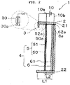
- Figure 2 is a cross-sectional view taken along an arrow A-A in Figure 1
- Figure 3 is an exploded perspective view of the electrostatic precipitator in Figure 1 showing a partially broken component.
- an electrostatic precipitator 1 of the present embodiment has a structure in which an ionization unit 3 and a dust collection unit 4 are incorporated in a case 2.
- the case 2 is an insulating quadrangular frame body opened in front (a front side in Figure 1 ) and rear (a rear side in Figure 1 ), and the ionization unit 3 is assembled in a front stage of the case 2, and the dust collection unit 4 is assembled from a middle stage to a rear stage of the case 2.
- the ionization unit 3 is a unit configured to generate ions, and includes an ionizer 30 and a power source 10.
- the ionizer 30 is attached to a center of a front end of a lower surface of an upper frame 21 of the case 2.
- the ionizer 30 is a direct current ionizer, and has an electrode needle 30a inside as shown in Figure 2 .
- a tip is disposed downward, and a rear end is connected to a positive electrode 10a of the power source 10 that generates a direct current voltage.
- a positive direct current voltage from the power source 10 is applied to the electrode needle 30a of the ionizer 30. Accordingly, a corona discharge can be generated at the tip of the electrode needle 30a, and air existing around the electrode needle 30a can be electrically decomposed to generate ions of positive polarity.
- a voltage applied to the electrode needle 30a usually needs to be in a range of 3 kV to 6 kV to generate the ions. That is, a direct current power source in the range of 3 kV to 6 kV is used as the power source 10.
- a polarity of the voltage applied to the electrode needle 30a is optional, but in the present embodiment, the positive direct current voltage is set to be applied.
- a direction of the electrode needle 30a and the voltage of the power source 10 are set such that the ions of positive polarity diffuse in front of the dust collection unit 4 in parallel with a surface of the dust collection unit 4.
- the dust collection unit 4 is a unit configured to electrically collect dust to which the ions are attached, and includes a high-voltage electrode 5 in a front stage and a dust collection board 6 in a rear stage.
- the high-voltage electrodes 5 of the dust collection unit 4 are a plurality of linear conductors 50 arranged in a rear stage of the ionization unit 3, and are connected to the power source 10.
- the plurality of linear conductors 50 are arranged side by side and parallel at predetermined intervals in an upright state.
- intervals G in which the plurality of linear conductors 50 are arranged side by side are gaps for passing the dust to which the ions are attached, and are set within a range of 40 mm to 100 mm.
- Each of the plurality of linear conductors 50 is covered with an insulator 51.
- Such a linear conductor 50 is as thin as possible and has a performance capable of withstanding a high voltage.
- the linear conductor 50 is preferably copper, nickel, or an alloy thereof, and the insulator 51 is preferably silicon.
- An upper end 50a of such the linear conductor 50 is connected to a band-shaped conductor 52a provided on the lower surface of the upper frame 21 of the case 2, and the band-shaped conductor 52a is connected to the positive electrode 10a of the power source 10.
- the positive direct current voltage from the power source 10 is applied to the plurality of linear conductors 50.
- the direct current voltages applied to the electrode needle 30a of the ionizer 30 and the plurality of linear conductors 50 are set to the same polarity and the same voltage value.
- the ions generated by the ionizer 30 can be prevented from being directly adsorbed on the dust collection board 6 by the plurality of linear conductors 50 constituting the high-voltage electrode 5, and the ions can be diffused by a repulsive action of the same polarity.
- the direct current voltages applied to the electrode needle 30a of the ionizer 30 and the plurality of linear conductors 50 are set to the same voltage value, and it is of course possible to set different voltage values if the polarities are the same.
- the dust collection board 6 of the dust collection unit 4 is a flat plate-shaped conductor disposed in a rear stage of the high-voltage electrode 5, and is connected to the power source 10.
- the dust collection board 6 is disposed to be rearward by a predetermined distance from the high-voltage electrode 5 in a state of standing perpendicular to a dust collecting direction (a right direction in Figure 2 ).
- a distance L1 from the electrode needle 30a of the ionizer 30 to the dust collection board 6 is set within a range of 30 mm to 100 mm, and a distance L2 from the high-voltage electrode 5 to the dust collection board 6 is set within a range of 10 mm to 80 mm.
- such a dust collection board 6 is covered with an insulator 61 separate from the insulator 51 of the linear conductor 50.
- the insulator 61 is an insulating resin film such as polyethylene terephthalate (PET).
- PET polyethylene terephthalate
- a volume resistivity of the insulator 61 is set in a range of 10 10 ⁇ /cm 3 to 10 13 ⁇ /cm 3 , and a thickness is set to about 0.1 mm.
- a conductor such as metal, such as copper foil or aluminum foil, or carbon can be applied.
- an upper end 6a of the dust collection board 6 coated with the insulator 61 is connected to a terminal 62a provided at the rear of the lower surface of the upper frame 21 of the case 2, and the terminal 62a is connected to a negative electrode 10b of the power source 10.
- a direct current voltage having a polarity opposite to the polarity of the voltage applied to the high-voltage electrode 5 is set to be applied to the dust collection board 6.
- This voltage value is a voltage value in a range of -500 V to 5 kV.
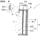
- Figure 4 is a cross-sectional view showing a state of generating the ions by the ionization unit 3
- Figure 5 is a cross-sectional view showing a dust collection state of the charged dust from above.
- the positive direct current voltage of the power source 10 is applied to the electrode needle 30a of the ionizer 30 and the linear conductors 50 of the high-voltage electrode 5, and the negative direct current voltage is applied to the dust collection board 6.
- the ions I are attempting to be drawn into a dust collection board 6 side, the positive direct current voltage having the same polarity as the ions I is applied to the linear conductors 50 of the high-voltage electrode 5, and thus, movement of the ions I to the dust collection board 6 side is prevented by the linear conductors 50 having the same polarity.
- a strong electric field E directed from the high voltage electrode 5 toward the dust collection board 6 is generated between the linear conductors 50 of the high-voltage electrode 5 and the dust collection board 6, and thus, once positively charged dust D passes through gaps of the intervals G of the high-voltage electrode 5, the charged dust D is rapidly drawn to the dust collection board 6 side by a strong force and is electrically adsorbed on the dust collection board 6.
- the electrostatic precipitator 1 of the present embodiment a large quantity of the dust is charged in a wide range, and the charged dust is strongly and quickly collected by the strong electric field between the high-voltage electrode 5 and the dust collection board 6.
- an inventor or the like conducted a dust collection capability comparison experiment between the electrostatic precipitator 1 of the present embodiment and an electrostatic precipitator in the prior art in which the high-voltage electrode 5 is removed from the electrostatic precipitator 1.
- the inventor or the like were able to confirm that the electrostatic precipitator 1 of the present embodiment has a very wide dust collection range and has a dust collection capability as compared with the electrostatic precipitator in the prior art.
- the plurality of linear conductors 50 which are the high-voltage electrodes 5, are interposed between the ionizer 30 and the dust collection board 6, and moreover, the polarity of the direct current voltage applied to the ionizer 30 and the polarity of the direct current voltage applied to the linear conductors 50 are set to the same polarity, and thus, an electric field is not directly generated between the ionizer 30 and the dust collection board 6. Therefore, almost no spark discharge occurs.
- the linear conductor 50 of the high-voltage electrode 5 is covered with the insulator 51 and the dust collection board 6 is covered with the insulator 61, the occurrence of the spark discharge can be greatly prevented, and the generation of ozone can be prevented.
- the inventor or the like drove the electrostatic precipitator 1 of the present embodiment under conditions of a room temperature of 20°C and an airflow rate of 20 L/min, and confirmed that generated ozone was 0.001 ppm or less, which is a measurement limit of an ozone concentration measuring device, and could not be detected.
- a device such as an ozone treatment device is not required, and thus, the small and thin electrostatic precipitator 1 having a thickness of 100 mm or less and having a high dust collection range and a high dust collection capability can be provided.
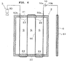
- Figure 6 is an exploded view for illustrating an electrostatic precipitator according to the second embodiment of the present invention.
- an electrical connection structure of a high-voltage electrode and an electrical connection structure of an ionizer are different from those of the above-described first embodiment.
- the above-described first embodiment shows an example of the high-voltage electrode having the structure in which the plurality of linear conductors 50 are connected in parallel to the positive electrode 10a of the power source 10 through the band-shaped conductor 52a, and in the present embodiment, as shown in Figure 6 , the single linear conductor 50 connected to the positive electrode 10a of the power supply 10 is applied as a high-voltage electrode.
- a plurality of holes 23 are provided in the upper frame 21 and a lower frame 22 of the case 2, and the single linear conductor 50 coated with the insulator 51 (not shown) passes through these holes 23 in a meandering manner like passing a shoelace. Then, by connecting a base end 50a of the linear conductor 50 to the positive electrode 10a of the power source 10, a high-voltage electrode having the same function as the high-voltage electrode of the above-described first embodiment is configured.
- power supply to the ionizer 30 of the ionization unit 3 is performed by an electric wire from the positive electrode 10a of the power source 10. Meanwhile, in the present embodiment, by connecting an end 50b of the linear conductor 50 to the ionizer 30 of the ionization unit 3, the linear conductor 50 is also used as an electric wire for supplying power to the ionizer 30 of the ionization unit 3.
- the electrical structure of the electrostatic precipitator is simplified by using such an electrical connection structure.
- the high-voltage electrode is formed by the plurality of parallel linear conductors 50 each coated with the insulator 51 as shown in Figure 3 , but the high-voltage electrode is not limited thereto.
- a flat plate-shaped electrode 53 which has a plurality of holes G1 as gaps, coated with an insulator 54 can also be applied as a high-voltage electrode.
- a mesh-shaped electrode 55 which has a plurality of gaps G2, coated with an insulator 56 can also be applied as a high-voltage electrode.
- the ionizer 30 having one electrode needle 30a inside is exemplified as the ionizer of the ionization unit 3, but the ionizer applicable to the electrostatic precipitator is not limited thereto.
- a so-called "carbon brush ionizer" in which electrode needles made of carbon conductive fibers are bundled in a brush shape can also be applied as the ionizer for the electrostatic precipitator.
Landscapes
- Physics & Mathematics (AREA)
- Engineering & Computer Science (AREA)
- Plasma & Fusion (AREA)
- Electrostatic Separation (AREA)
Abstract
Description
- The present invention relates to an electrostatic precipitator that collects dust in air by using an electric field.
- At a manufacturing site, a device that collects dust only for a part of processes, that is, a device that locally collects dust in air, is desired.
- Generally, as a technical means for removing dust in air, an air purifier using a filter or an electrostatic precipitator using an electric field is present.
- An electrostatic precipitator includes a one-stage electrostatic precipitator and a two-stage electrostatic precipitator.
- As described in
Patent Literature 1 andPatent Literature 2, a one-stage electrostatic precipitator has a structure in which dust in air is directly collected on a dust collection board by using an ionization unit as a high-voltage electrode and the dust collection board as a counter electrode. - Therefore, a one-stage electrostatic precipitator is often adopted as a small and thin electrostatic precipitator because of having a simple structure and being able to collect dust without power.
- Meanwhile, as described in
Patent Literature 3 andPatent Literature 4, a two-stage electrostatic precipitator has a structure divided into two stages of an ionization unit configured to charge dust, and a dust collection unit including a high-voltage electrode and a dust collection board configured to collect the dust charged by an electric field. - In particular, the electrostatic precipitators described in
Patent Literature 3 andPatent Literature 4 adopt a technique in which the dust collection board or the high-voltage electrode is made of a semi-insulating material to prevent a decrease in a dust collecting efficiency due to a spark discharge. -
- Patent Literature 1:
Japanese Published examined patent application No. H02-029385 B2 - Patent Literature 2:
Japanese Published unexamined patent application No. H07-256145 A - Patent Literature 3:
Japanese Published unexamined patent application No. H08-071451 A - Patent Literature 4:
Japanese Published unexamined patent application No. H09-253525 A - However, the above-described electrostatic precipitators in the prior art have the following problems.
- The one-stage electrostatic precipitator disclosed in
Patent Literature 1 can obtain a spread of an electric field, but has a drawback that a Coulomb force is weakened because a source of the electric field is far away. Accordingly, with such a weak Coulomb force, the dust that can be collected is limited to small dust. In addition, with the weak Coulomb force, it is difficult to strongly retain the dust on the dust collection board, and the dust may be peeled off by wind or the like. Therefore, there is a problem that the air is polluted again by the peeled off dust. - In addition, in the one-stage electrostatic precipitator disclosed in
Patent Literature 2, a strong electric field can be obtained, but generation of the electric field is limited between a discharge electrode and the dust collection board. Therefore, there is a problem that ions are immediately attracted to the dust collection board, the ions do not spread sufficiently, and a dust collection range is narrow. - That is, both the above-described one-stage electrostatic precipitators have a problem that effective dust collection cannot be performed because the dust collection range is narrow and a dust collection capability is low.
- Meanwhile, compared with a one-stage electrostatic precipitator, a two-stage electrostatic precipitator has a wider dust collection range and extremely higher dust collection capability, but it is necessary to separately provide an ionization unit and a dust collection unit in order to prevent a spark discharge. Therefore, it is necessary to have a power to drive these units, and it is necessary to include other units such as an ozone treatment device and linearly connect devices such as the ionization unit. As a result, in the two-stage electrostatic precipitator, the equipment itself becomes large, and this two-stage electrostatic precipitator cannot be used as a local dust collector for only a part of processes.
- The present invention has been made to solve the above-described problems, and an object of the present invention is to provide an electrostatic precipitator having a wide dust collection range, a high dust collection capability, and being able to be miniaturized and thinned.
- In order to solve the above-described problems, a first invention is an electrostatic precipitator comprising an ionization unit configured to generate ions and a dust collection unit configured to electrically collect dust to which the ions are attached, in which the ionization unit is an ionizer that applies a predetermined voltage to an electrode needle to cause a corona discharge to generate the ions having the same polarity as a polarity of the applied voltage, the dust collection unit includes a high-voltage electrode disposed at a rear stage of the ionization unit, having a plurality of gaps for passing the dust to which the ions are attached, and applied with a predetermined voltage, and a dust collection board disposed at a rear stage of the high-voltage electrode and applied with a voltage having a polarity opposite to a polarity of the voltage applied to the high-voltage electrode to electrically adsorb the dust to which the ions are attached, a polarity of the voltage applied to the electrode needle of the ionization unit and the polarity of the voltage applied to the high-voltage electrode are set to the same polarity, and the high-voltage electrode of the dust collection unit is covered with an insulator, and the dust collection board is covered with an insulator separate from the insulator.
- According to such a configuration, when the predetermined voltages of the same polarity are applied to the ionization unit and the high-voltage electrode, and the predetermined voltage of the opposite polarity is applied to the dust collection board, the corona discharge occurs in the ionization unit, and a large quantity of the ions having the same polarity as the applied voltage are generated from the ionization unit. In this case, the voltage having the same polarity as the ions is applied to the high-voltage electrode disposed in the rear stage of the ionization unit, and thus, the large quantity of the ions are repelled by the high-voltage electrode, and movement to a dust collection board side is prevented. That is, the high-voltage electrode having the same polarity as the ions are interposed between the ionization unit and the dust collection board, and prevents an electric field from being created directly between the ionization unit and the dust collection board. Accordingly, the large quantity of the ions diffuse widely in front of the high-voltage electrode without facing the dust collection board side, and adhere to the dust in a wide range. As a result, the wide range of the dust is charged.
- After passing through the gaps of the high-voltage electrode, the charged dust is drawn to the dust collection board side by a strong electric field generated between the high-voltage electrode and the dust collection board, and is electrically adsorbed to the dust collection board. That is, the electrostatic precipitator of the present invention has a capability to charge the dust in a wide range and efficiently collect a large quantity of the charged dust by the strong electric field.
- By the way, if a distance between the ionization unit and the dust collection board is short, a spark discharge may occur and ozone may be generated. Moreover, since an energy that should be donated to generation of the ions is used for the spark discharge, a dust collection efficiency may be lowered.
- However, in the electrostatic precipitator of the present invention, as described above, the high-voltage electrode is interposed between the ionization unit and the dust collection board, and the polarity of the voltage applied to the ionization unit and the polarity of the voltage applied to the high-voltage electrode are set to be the same, and thus, the electric field is not directly generated between the ionization unit and the dust collection board. Therefore, almost no spark discharge occurs. Moreover, since the high-voltage electrode and the dust collection board are covered with the insulators, the occurrence of the spark discharge can be reliably prevented.
- A second invention has a configuration in which in the electrostatic precipitator described in the first invention, the high-voltage electrode of the dust collection unit is formed by a plurality of linear conductors arranged in parallel at a predetermined interval and each coated with an insulator, and the dust collection board of the dust collection unit is formed by a flat conductor coated with an insulating resin film.
- According to such a configuration, by forming the high-voltage electrode with the plurality of linear conductors arranged in parallel and coated with the insulators, the generation of the electric field between the ionization unit and the high-voltage electrode can be prevented and a strong electric field between the high-voltage electrode and the dust collection board can be generated, and moreover, the charged dust can be reliably passed and smoothly moved to the dust collection board side. By forming the dust collection board with a structure in which the conductor is covered with the insulating resin film, an effect of preventing the spark discharge can be enhanced.
- A third invention has a configuration in which in the electrostatic precipitator described in the second invention, a volume resistivity of the resin film is set in a range of 1010 Ω/cm3 to 1013 Ω/cm3, a thickness thereof is set to about 0.1 mm, and the distance from the ionization unit to the dust collection board of the dust collection unit is set to 100 mm or less.
- A fourth invention has a configuration in which in the electrostatic precipitator described in the second invention or the third invention, a distance between the plurality of linear conductors forming the high-voltage electrode is set within a range of 40 mm to 100 mm, a distance between the high-voltage electrode formed by the plurality of linear conductors and the dust collection board is set within a range of 10 mm to 80 mm, and a distance from the electrode needle of the ionization unit to the dust collection board of the dust collection unit is set within a range of 30 mm to 100 mm.
- A fifth invention has a configuration in which in the electrostatic precipitator described in the second invention to the fourth invention, the ionizer is a direct current ionizer that generates ions by applying a direct current voltage, and the voltages applied to the high-voltage electrode and the dust collection board are direct current voltages having opposite polarities.
- As described in detail above, according to the electrostatic precipitator of the present invention, a wide range of dust can be charged and the large quantity of the charged dust can be collected with the strong electric field. Further, by setting the voltage polarity of the high-voltage electrode and the ionization unit to the same polarity and covering the high voltage electrode and the dust collection board with the insulators, the occurrence of the spark discharge can be reliably prevented, and thus, a device such as an ozone treatment device becomes unnecessary, and the entire device can be miniaturized and thinned. That is, the electrostatic precipitator of the present invention has an excellent effect that a wide dust collection range and a high dust collection capability can be secured, and moreover, miniaturization and thinning can be realized.
- According to the second invention, the dust collection capability and an effect of preventing the spark discharge can be further enhanced.
- According to the third and fourth inventions, the device can be further miniaturized and thinned.
-
- [
Figure 1] Figure 1 is a perspective view showing an electrostatic precipitator according to a first embodiment of the present invention. - [
Figure 2] Figure 2 is a cross-sectional view taken along an arrow A-A inFigure 1 . - [
Figure 3] Figure 3 is an exploded perspective view of the electrostatic precipitator inFigure 1 showing a partially broken component. - [
Figure 4] Figure 4 is a cross-sectional view showing a state of generating ions by anionization unit 3. - [
Figure 5] Figure 5 is a cross-sectional view showing a dust collection state of charged dust from above. - [
Figure 6] Figure 6 is an exploded view for illustrating an electrostatic precipitator according to a second embodiment of the present invention. - [
Figure 7] Figure 7 is a plan view showing a modification of a high-voltage electrode. - [
Figure 8] Figure 8 is a plan view showing another modification of the high-voltage electrode. - Hereinafter, embodiments of the present invention will be described with reference to the drawings.
-
Figure 1 is a perspective view showing an electrostatic precipitator according to a first embodiment of the present invention,Figure 2 is a cross-sectional view taken along an arrow A-A inFigure 1 , andFigure 3 is an exploded perspective view of the electrostatic precipitator inFigure 1 showing a partially broken component. - As shown in
Figure 1 , anelectrostatic precipitator 1 of the present embodiment has a structure in which anionization unit 3 and adust collection unit 4 are incorporated in acase 2. - The
case 2 is an insulating quadrangular frame body opened in front (a front side inFigure 1 ) and rear (a rear side inFigure 1 ), and theionization unit 3 is assembled in a front stage of thecase 2, and thedust collection unit 4 is assembled from a middle stage to a rear stage of thecase 2. - The
ionization unit 3 is a unit configured to generate ions, and includes anionizer 30 and apower source 10. - The
ionizer 30 is attached to a center of a front end of a lower surface of anupper frame 21 of thecase 2. Theionizer 30 is a direct current ionizer, and has anelectrode needle 30a inside as shown inFigure 2 . In theelectrode needle 30a, a tip is disposed downward, and a rear end is connected to apositive electrode 10a of thepower source 10 that generates a direct current voltage. - That is, a positive direct current voltage from the
power source 10 is applied to theelectrode needle 30a of theionizer 30. Accordingly, a corona discharge can be generated at the tip of theelectrode needle 30a, and air existing around theelectrode needle 30a can be electrically decomposed to generate ions of positive polarity. - A voltage applied to the
electrode needle 30a usually needs to be in a range of 3 kV to 6 kV to generate the ions. That is, a direct current power source in the range of 3 kV to 6 kV is used as thepower source 10. - A polarity of the voltage applied to the
electrode needle 30a is optional, but in the present embodiment, the positive direct current voltage is set to be applied. - That is, a direction of the
electrode needle 30a and the voltage of thepower source 10 are set such that the ions of positive polarity diffuse in front of thedust collection unit 4 in parallel with a surface of thedust collection unit 4. - The
dust collection unit 4 is a unit configured to electrically collect dust to which the ions are attached, and includes a high-voltage electrode 5 in a front stage and adust collection board 6 in a rear stage. - The high-
voltage electrodes 5 of thedust collection unit 4 are a plurality oflinear conductors 50 arranged in a rear stage of theionization unit 3, and are connected to thepower source 10. - As shown in
Figure 3 , the plurality oflinear conductors 50 are arranged side by side and parallel at predetermined intervals in an upright state. - The intervals, that is, intervals G in which the plurality of
linear conductors 50 are arranged side by side are gaps for passing the dust to which the ions are attached, and are set within a range of 40 mm to 100 mm. - Each of the plurality of
linear conductors 50 is covered with aninsulator 51. - It is desirable that such a
linear conductor 50 is as thin as possible and has a performance capable of withstanding a high voltage. - For example, the
linear conductor 50 is preferably copper, nickel, or an alloy thereof, and theinsulator 51 is preferably silicon. - An
upper end 50a of such thelinear conductor 50 is connected to a band-shapedconductor 52a provided on the lower surface of theupper frame 21 of thecase 2, and the band-shapedconductor 52a is connected to thepositive electrode 10a of thepower source 10. - Accordingly, the positive direct current voltage from the
power source 10 is applied to the plurality oflinear conductors 50. - That is, as shown in
Figure 2 , in theelectrostatic precipitator 1 of the present embodiment, the direct current voltages applied to theelectrode needle 30a of theionizer 30 and the plurality oflinear conductors 50 are set to the same polarity and the same voltage value. - Accordingly, by setting the direct current voltages applied to the
electrode needle 30a of theionizer 30 and the plurality oflinear conductors 50 to the same polarity, the ions generated by theionizer 30 can be prevented from being directly adsorbed on thedust collection board 6 by the plurality oflinear conductors 50 constituting the high-voltage electrode 5, and the ions can be diffused by a repulsive action of the same polarity. - In the present embodiment, the direct current voltages applied to the
electrode needle 30a of theionizer 30 and the plurality oflinear conductors 50 are set to the same voltage value, and it is of course possible to set different voltage values if the polarities are the same. - As shown in
Figure 3 , thedust collection board 6 of thedust collection unit 4 is a flat plate-shaped conductor disposed in a rear stage of the high-voltage electrode 5, and is connected to thepower source 10. - The
dust collection board 6 is disposed to be rearward by a predetermined distance from the high-voltage electrode 5 in a state of standing perpendicular to a dust collecting direction (a right direction inFigure 2 ). - As shown in
Figure 2 , a distance L1 from theelectrode needle 30a of theionizer 30 to thedust collection board 6 is set within a range of 30 mm to 100 mm, and a distance L2 from the high-voltage electrode 5 to thedust collection board 6 is set within a range of 10 mm to 80 mm. - As shown in
Figure 3 , such adust collection board 6 is covered with aninsulator 61 separate from theinsulator 51 of thelinear conductor 50. - The
insulator 61 is an insulating resin film such as polyethylene terephthalate (PET). A volume resistivity of theinsulator 61 is set in a range of 1010 Ω/cm3 to 1013 Ω/cm3, and a thickness is set to about 0.1 mm. - As the
dust collection board 6, a conductor such as metal, such as copper foil or aluminum foil, or carbon can be applied. - Accordingly, as shown in
Figure 2 , anupper end 6a of thedust collection board 6 coated with theinsulator 61 is connected to a terminal 62a provided at the rear of the lower surface of theupper frame 21 of thecase 2, and the terminal 62a is connected to anegative electrode 10b of thepower source 10. - Accordingly, a negative direct current voltage from the
power source 10 is applied to thedust collection board 6. - That is, in the
electrostatic precipitator 1 of the present embodiment, a direct current voltage having a polarity opposite to the polarity of the voltage applied to the high-voltage electrode 5 is set to be applied to thedust collection board 6. This voltage value is a voltage value in a range of -500 V to 5 kV. - As described above, when the voltage having the polarity opposite to that of the high-
voltage electrode 5 is applied to thedust collection board 6, a strong electric field is generated between the high-voltage electrode 5 and thedust collection board 6, and charged dust that has passed through the intervals G of the high-voltage electrode 5 can be quickly adsorbed to thedust collection board 6 with a strong force. - Next, functions and effects of the
electrostatic precipitator 1 of the present embodiment will be described. -
Figure 4 is a cross-sectional view showing a state of generating the ions by theionization unit 3, andFigure 5 is a cross-sectional view showing a dust collection state of the charged dust from above. - In
Figure 2 , the positive direct current voltage of thepower source 10 is applied to theelectrode needle 30a of theionizer 30 and thelinear conductors 50 of the high-voltage electrode 5, and the negative direct current voltage is applied to thedust collection board 6. - Then, by applying the positive direct current voltage to the
electrode needle 30a of theionizer 30, as shown inFigure 4 , ions I of positive polarity are generated at a tip portion of theelectrode needle 30a, and a large quantity of the ions I are diffused to the surroundings. - In this case, the ions I are attempting to be drawn into a
dust collection board 6 side, the positive direct current voltage having the same polarity as the ions I is applied to thelinear conductors 50 of the high-voltage electrode 5, and thus, movement of the ions I to thedust collection board 6 side is prevented by thelinear conductors 50 having the same polarity. - That is, since the
linear conductors 50 to which the voltage having the same polarity as the ions I are applied are interposed between theionizer 30 and thedust collection board 6, an electric field is not directly formed between theelectrode needle 30a of theionizer 30 and thedust collection board 6. - Therefore, a large quantity of the ions I are widely diffused in front of the high-
voltage electrode 5 without being drawn by thedust collection board 6, and adheres to the dust existing in a wide space in front of the high-voltage electrode 5. That is, presence of the high-voltage electrode 5 to which the voltage having the same polarity as that of theionizer 30 is applied causes the dust in a wide range to be charged. - As shown in
Figure 5 , a strong electric field E directed from thehigh voltage electrode 5 toward thedust collection board 6 is generated between thelinear conductors 50 of the high-voltage electrode 5 and thedust collection board 6, and thus, once positively charged dust D passes through gaps of the intervals G of the high-voltage electrode 5, the charged dust D is rapidly drawn to thedust collection board 6 side by a strong force and is electrically adsorbed on thedust collection board 6. - That is, according to the
electrostatic precipitator 1 of the present embodiment, a large quantity of the dust is charged in a wide range, and the charged dust is strongly and quickly collected by the strong electric field between the high-voltage electrode 5 and thedust collection board 6. - In order to demonstrate such a point, an inventor or the like conducted a dust collection capability comparison experiment between the
electrostatic precipitator 1 of the present embodiment and an electrostatic precipitator in the prior art in which the high-voltage electrode 5 is removed from theelectrostatic precipitator 1. - As a result, in the electrostatic precipitator in the prior art, it was possible to collect only dust in a radius of about 100 mm from the
ionizer 30 of theionization unit 3. Meanwhile, in theelectrostatic precipitator 1 of the present embodiment, it was possible to collect dust in a range of 400 mm or more from theionizer 30. - As a result, the inventor or the like were able to confirm that the
electrostatic precipitator 1 of the present embodiment has a very wide dust collection range and has a dust collection capability as compared with the electrostatic precipitator in the prior art. - By the way, if a distance between the
ionizer 30 of theionization unit 3 and thedust collection board 6 is short, a spark discharge may occur and ozone may be generated from theionizer 30 toward thedust collection board 6. - However, in the
electrostatic precipitator 1 of the present embodiment, the plurality oflinear conductors 50, which are the high-voltage electrodes 5, are interposed between theionizer 30 and thedust collection board 6, and moreover, the polarity of the direct current voltage applied to theionizer 30 and the polarity of the direct current voltage applied to thelinear conductors 50 are set to the same polarity, and thus, an electric field is not directly generated between theionizer 30 and thedust collection board 6. Therefore, almost no spark discharge occurs. Moreover, since thelinear conductor 50 of the high-voltage electrode 5 is covered with theinsulator 51 and thedust collection board 6 is covered with theinsulator 61, the occurrence of the spark discharge can be greatly prevented, and the generation of ozone can be prevented. - In order to demonstrate such a point, the inventor or the like drove the
electrostatic precipitator 1 of the present embodiment under conditions of a room temperature of 20°C and an airflow rate of 20 L/min, and confirmed that generated ozone was 0.001 ppm or less, which is a measurement limit of an ozone concentration measuring device, and could not be detected. - That is, according to the present embodiment, a device such as an ozone treatment device is not required, and thus, the small and thin
electrostatic precipitator 1 having a thickness of 100 mm or less and having a high dust collection range and a high dust collection capability can be provided. - Next, a second embodiment will be described.
-
Figure 6 is an exploded view for illustrating an electrostatic precipitator according to the second embodiment of the present invention. - In the electrostatic precipitator of the present embodiment, an electrical connection structure of a high-voltage electrode and an electrical connection structure of an ionizer are different from those of the above-described first embodiment.
- That is, the above-described first embodiment shows an example of the high-voltage electrode having the structure in which the plurality of
linear conductors 50 are connected in parallel to thepositive electrode 10a of thepower source 10 through the band-shapedconductor 52a, and in the present embodiment, as shown inFigure 6 , the singlelinear conductor 50 connected to thepositive electrode 10a of thepower supply 10 is applied as a high-voltage electrode. - Specifically, a plurality of
holes 23 are provided in theupper frame 21 and alower frame 22 of thecase 2, and the singlelinear conductor 50 coated with the insulator 51 (not shown) passes through theseholes 23 in a meandering manner like passing a shoelace. Then, by connecting abase end 50a of thelinear conductor 50 to thepositive electrode 10a of thepower source 10, a high-voltage electrode having the same function as the high-voltage electrode of the above-described first embodiment is configured. - In the above-described first embodiment, power supply to the
ionizer 30 of theionization unit 3 is performed by an electric wire from thepositive electrode 10a of thepower source 10. Meanwhile, in the present embodiment, by connecting anend 50b of thelinear conductor 50 to theionizer 30 of theionization unit 3, thelinear conductor 50 is also used as an electric wire for supplying power to theionizer 30 of theionization unit 3. - The electrical structure of the electrostatic precipitator is simplified by using such an electrical connection structure.
- Since other configurations, functions, and effects are the same as those in the first embodiment, descriptions thereof will be omitted.
- The present invention is not limited to the above-described embodiments, and various modifications and changes can be made within the scope of the gist of the invention.
- For example, in the above embodiment, the high-voltage electrode is formed by the plurality of parallel
linear conductors 50 each coated with theinsulator 51 as shown inFigure 3 , but the high-voltage electrode is not limited thereto. - For example, as shown in
Figure 7 , a flat plate-shapedelectrode 53, which has a plurality of holes G1 as gaps, coated with aninsulator 54 can also be applied as a high-voltage electrode. - As shown in
Figure 8 , a mesh-shapedelectrode 55, which has a plurality of gaps G2, coated with aninsulator 56 can also be applied as a high-voltage electrode. - Further, in the above embodiments, in order to facilitate the understanding of the corona discharge, the
ionizer 30 having oneelectrode needle 30a inside is exemplified as the ionizer of theionization unit 3, but the ionizer applicable to the electrostatic precipitator is not limited thereto. For example, a so-called "carbon brush ionizer" in which electrode needles made of carbon conductive fibers are bundled in a brush shape can also be applied as the ionizer for the electrostatic precipitator. Description of the reference numerals - 1 electrostatic precipitator; 2 case; 3 ionization unit; 4 dust collection unit; 5 high-voltage electrode; 6 dust collection board; 6a upper end; 10 power source; 10a positive electrode; 10b negative electrode; 21 upper frame; 22 lower frame; 23 hole; 30 ionizer; 30a electrode needle; 50 linear conductor; 50a upper end (base end); 50b end; 51, 54, 56, 61 insulator; 52a band-shaped conductor; 53, 55 electrode; 62a terminal; E electric field; G, G2 interval; G1 hole; I ion; D charged dust
Claims (4)
- An electrostatic precipitator comprising:an ionization unit configured to generate ions; anda dust collection unit configured to electrically collect dust to which the ions are attached,wherein the ionization unit is an ionizer that applies a predetermined voltage to an electrode needle to cause a corona discharge to generate the ions having the same polarity as a polarity of the applied voltage,wherein the dust collection unit includes:a high-voltage electrode disposed at a rear stage of the ionization unit, having a plurality of gaps for passing the dust to which the ions are attached, and applied with a predetermined voltage; and a dust collection board disposed at a rear stage of the high-voltage electrode and applied with a voltage having a polarity opposite to a polarity of the voltage applied to the high-voltage electrode to electrically adsorb the dust to which the ions are attached,wherein a polarity of the voltage applied to the electrode needle of the ionization unit and the polarity of the voltage applied to the high-voltage electrode are set to the same polarity,wherein the high-voltage electrode of the dust collection unit is formed by a plurality of linear conductors arranged in parallel at a predetermined interval and each coated with an insulator, andwherein the dust collection board of the dust collection unit is formed by a flat conductor coated with an insulating resin film.
- An electrostatic precipitator according to Claim 1,
wherein a volume resistivity of the resin film is set in a range of 1010 Ω/cm3 to 1013 Ω/cm3, a thickness thereof is set to about 0.1 mm, and the distance from the ionization unit to the dust collection board of the dust collection unit is set to 100 mm or less. - An electrostatic precipitator according to Claim 1 or 2,wherein a distance between the plurality of linear conductors forming the high-voltage electrode is set within a range of 40 mm to 100 mm,wherein a distance between the high-voltage electrode formed by the plurality of linear conductors and the dust collection board is set within a range of 10 mm to 80 mm, andwherein a distance from the electrode needle of the ionization unit to the dust collection board of the dust collection unit is set within a range of 30 mm to 100 mm.
- An electrostatic precipitator according to any one of Claims 1 to 3,wherein the ionizer is a direct current ionizer that generates ions by applying a direct current voltage, andwherein the voltages applied to the high-voltage electrode and the dust collection board are direct current voltages having opposite polarities.
Applications Claiming Priority (2)
| Application Number | Priority Date | Filing Date | Title |
|---|---|---|---|
| JP2019239850 | 2019-12-27 | ||
| PCT/JP2020/044523 WO2021131519A1 (en) | 2019-12-27 | 2020-11-30 | Electrostatic precipitator |
Publications (2)
| Publication Number | Publication Date |
|---|---|
| EP4084243A1 true EP4084243A1 (en) | 2022-11-02 |
| EP4084243A4 EP4084243A4 (en) | 2024-01-24 |
Family
ID=76573889
Family Applications (1)
| Application Number | Title | Priority Date | Filing Date |
|---|---|---|---|
| EP20908122.3A Pending EP4084243A4 (en) | 2019-12-27 | 2020-11-30 | Electrostatic precipitator |
Country Status (7)
| Country | Link |
|---|---|
| US (1) | US12551902B2 (en) |
| EP (1) | EP4084243A4 (en) |
| JP (1) | JP7541364B2 (en) |
| KR (1) | KR20220113718A (en) |
| CN (1) | CN114901397B (en) |
| TW (1) | TWI879849B (en) |
| WO (1) | WO2021131519A1 (en) |
Cited By (1)
| Publication number | Priority date | Publication date | Assignee | Title |
|---|---|---|---|---|
| EP4458475A4 (en) * | 2021-12-28 | 2026-01-07 | Creative Tech Corp | ELECTROSTATIC SEPARATOR |
Families Citing this family (3)
| Publication number | Priority date | Publication date | Assignee | Title |
|---|---|---|---|---|
| CN117816377B (en) * | 2024-01-15 | 2026-07-31 | 浙江菲达环保科技股份有限公司 | Dielectric barrier electrostatic precipitator |
| CN222761096U (en) * | 2024-03-01 | 2025-04-15 | 广东美的环境电器制造有限公司 | Air purification equipment |
| CN118491705B (en) * | 2024-06-07 | 2025-06-10 | 爱优特空气技术(上海)有限公司 | Charging device and assembling method |
Family Cites Families (22)
| Publication number | Priority date | Publication date | Assignee | Title |
|---|---|---|---|---|
| JPS52132472A (en) * | 1976-04-29 | 1977-11-07 | Nissan Motor Co Ltd | Air cleaner for use in automotive vehicles |
| JPS59139953A (en) | 1983-01-27 | 1984-08-11 | Sumitoku Sangyo Kk | Vertical type magnetic separator |
| JPS60122062A (en) * | 1983-12-05 | 1985-06-29 | Nippon Soken Inc | Air purifier |
| JPS60132661A (en) | 1983-12-20 | 1985-07-15 | Nippon Soken Inc | Air purifier |
| JP2740846B2 (en) | 1988-07-19 | 1998-04-15 | 株式会社リコー | Optical information recording medium |
| US5055963A (en) | 1990-08-15 | 1991-10-08 | Ion Systems, Inc. | Self-balancing bipolar air ionizer |
| RU2026751C1 (en) * | 1992-05-13 | 1995-01-20 | Елена Владимировна Володина | Device for sterilization and fine gas filtration |
| JPH07108191A (en) * | 1993-10-14 | 1995-04-25 | Daikin Ind Ltd | Electric dust collector |
| JPH07256145A (en) | 1994-03-25 | 1995-10-09 | Kankiyoo:Kk | air purifier |
| JP3516725B2 (en) | 1994-09-05 | 2004-04-05 | ミドリ安全株式会社 | Electrostatic dust collector |
| JPH09253525A (en) | 1996-03-25 | 1997-09-30 | Zexel Corp | Vehicle air purifier |
| WO2001064349A1 (en) | 2000-03-03 | 2001-09-07 | Matsushita Seiko Co., Ltd. | Dust collecting apparatus and air-conditioning apparatus |
| JP3976611B2 (en) | 2002-05-01 | 2007-09-19 | ミドリ安全株式会社 | Ion removal apparatus and ion removal method |
| KR100688945B1 (en) * | 2002-12-23 | 2007-03-09 | 삼성전자주식회사 | Device For Collecting A Dust In An Air Purifying System |
| CN1541771A (en) * | 2003-04-30 | 2004-11-03 | 乐金电子(天津)电器有限公司 | Electric dust collecting filter of air purifier |
| JP3742863B2 (en) | 2004-07-02 | 2006-02-08 | ダイキン工業株式会社 | Air purification device |
| JP3832490B2 (en) | 2005-02-14 | 2006-10-11 | ダイキン工業株式会社 | Air purification device |
| US20120000627A1 (en) * | 2010-06-30 | 2012-01-05 | Tessera, Inc. | Electrostatic precipitator pre-filter for electrohydrodynamic fluid mover |
| KR101858940B1 (en) * | 2011-06-10 | 2018-05-17 | 삼성전자주식회사 | Electrostatic precipitator |
| KR102199377B1 (en) | 2014-07-08 | 2021-01-06 | 엘지전자 주식회사 | Filter and air conditioner having the same |
| NL2013690B1 (en) | 2014-10-27 | 2016-10-04 | Pieter Hendrik Bruinsma | Device and method for capturing condensation cores from ambient air |
| JP2017013041A (en) * | 2014-12-22 | 2017-01-19 | 三星電子株式会社Samsung Electronics Co.,Ltd. | Electrostatic precipitator |
-
2020
- 2020-11-30 EP EP20908122.3A patent/EP4084243A4/en active Pending
- 2020-11-30 WO PCT/JP2020/044523 patent/WO2021131519A1/en not_active Ceased
- 2020-11-30 KR KR1020227020821A patent/KR20220113718A/en active Pending
- 2020-11-30 CN CN202080090304.5A patent/CN114901397B/en active Active
- 2020-11-30 JP JP2021567106A patent/JP7541364B2/en active Active
- 2020-11-30 US US17/788,795 patent/US12551902B2/en active Active
- 2020-12-16 TW TW109144511A patent/TWI879849B/en active
Cited By (1)
| Publication number | Priority date | Publication date | Assignee | Title |
|---|---|---|---|---|
| EP4458475A4 (en) * | 2021-12-28 | 2026-01-07 | Creative Tech Corp | ELECTROSTATIC SEPARATOR |
Also Published As
| Publication number | Publication date |
|---|---|
| KR20220113718A (en) | 2022-08-16 |
| JP7541364B2 (en) | 2024-08-28 |
| TWI879849B (en) | 2025-04-11 |
| TW202130419A (en) | 2021-08-16 |
| WO2021131519A1 (en) | 2021-07-01 |
| US12551902B2 (en) | 2026-02-17 |
| US20230046930A1 (en) | 2023-02-16 |
| EP4084243A4 (en) | 2024-01-24 |
| CN114901397B (en) | 2025-01-28 |
| CN114901397A (en) | 2022-08-12 |
| JPWO2021131519A1 (en) | 2021-07-01 |
Similar Documents
| Publication | Publication Date | Title |
|---|---|---|
| US12551902B2 (en) | Electrostatic precipitator | |
| CN107107074B (en) | Electrostatic dust collector | |
| US4673416A (en) | Air cleaning apparatus | |
| KR20170102978A (en) | Ion generator and electrical equipment | |
| JPWO2021131519A5 (en) | ||
| EP0367459A1 (en) | Static electric discharge apparatus | |
| JP2000218193A (en) | Electric dust collector | |
| JP4002948B2 (en) | Ion generator | |
| HK40071078A (en) | Electrostatic precipitator | |
| CN211914193U (en) | Air purification apparatus for separating airborne particles from an air stream | |
| HK40071078B (en) | Electrostatic precipitator | |
| US20250121379A1 (en) | Electrostatic precipitator | |
| JP5223424B2 (en) | Dust collector | |
| KR200179330Y1 (en) | Electrode films for a electric dust collector | |
| JPS62149359A (en) | Electricstatic precipitator | |
| CN222925681U (en) | Electrostatic dust removing module and air conditioner | |
| KR200179856Y1 (en) | Electrode films for a electric dust collector | |
| KR200179858Y1 (en) | Electrode films for a electric dust collector | |
| KR970058784A (en) | Electric dust collector | |
| CN211914182U (en) | Air purification apparatus for separating airborne particles from an air stream | |
| CN211914181U (en) | Emitter unit for air cleaning device | |
| CN222761096U (en) | Air purification equipment | |
| KR20000004183U (en) | Electrode films for a electric dust collector | |
| KR19980066229A (en) | Electric dust collecting and deodorizing device | |
| JP2011016056A (en) | Electrostatic precipitator and air cleaner |
Legal Events
| Date | Code | Title | Description |
|---|---|---|---|
| STAA | Information on the status of an ep patent application or granted ep patent |
Free format text: STATUS: THE INTERNATIONAL PUBLICATION HAS BEEN MADE |
|
| PUAI | Public reference made under article 153(3) epc to a published international application that has entered the european phase |
Free format text: ORIGINAL CODE: 0009012 |
|
| STAA | Information on the status of an ep patent application or granted ep patent |
Free format text: STATUS: REQUEST FOR EXAMINATION WAS MADE |
|
| 17P | Request for examination filed |
Effective date: 20220706 |
|
| AK | Designated contracting states |
Kind code of ref document: A1 Designated state(s): AL AT BE BG CH CY CZ DE DK EE ES FI FR GB GR HR HU IE IS IT LI LT LU LV MC MK MT NL NO PL PT RO RS SE SI SK SM TR |
|
| DAV | Request for validation of the european patent (deleted) | ||
| DAX | Request for extension of the european patent (deleted) | ||
| A4 | Supplementary search report drawn up and despatched |
Effective date: 20240102 |
|
| RIC1 | Information provided on ipc code assigned before grant |
Ipc: B03C 3/64 20060101ALI20231219BHEP Ipc: B03C 3/47 20060101ALI20231219BHEP Ipc: B03C 3/41 20060101ALI20231219BHEP Ipc: B03C 3/40 20060101ALI20231219BHEP Ipc: H01T 19/04 20060101AFI20231219BHEP |