EP4084207A1 - Electrode assembly, battery cell, battery, electric apparatus, and manufacturing method and device - Google Patents
Electrode assembly, battery cell, battery, electric apparatus, and manufacturing method and device Download PDFInfo
- Publication number
- EP4084207A1 EP4084207A1 EP20958029.9A EP20958029A EP4084207A1 EP 4084207 A1 EP4084207 A1 EP 4084207A1 EP 20958029 A EP20958029 A EP 20958029A EP 4084207 A1 EP4084207 A1 EP 4084207A1
- Authority
- EP
- European Patent Office
- Prior art keywords
- electrode assembly
- body portion
- metal substrate
- protruding portion
- electrode
- Prior art date
- Legal status (The legal status is an assumption and is not a legal conclusion. Google has not performed a legal analysis and makes no representation as to the accuracy of the status listed.)
- Pending
Links
- 238000004519 manufacturing process Methods 0.000 title claims abstract description 15
- 229910052751 metal Inorganic materials 0.000 claims abstract description 97
- 239000002184 metal Substances 0.000 claims abstract description 97
- 239000000758 substrate Substances 0.000 claims abstract description 97
- 239000011149 active material Substances 0.000 claims abstract description 51
- 239000000463 material Substances 0.000 claims description 89
- 238000012545 processing Methods 0.000 claims description 12
- 239000011248 coating agent Substances 0.000 claims description 11
- 238000000576 coating method Methods 0.000 claims description 11
- 238000000034 method Methods 0.000 claims description 4
- 238000004804 winding Methods 0.000 claims description 3
- 238000010586 diagram Methods 0.000 description 15
- 238000003466 welding Methods 0.000 description 12
- 238000007599 discharging Methods 0.000 description 10
- 229910052782 aluminium Inorganic materials 0.000 description 6
- XAGFODPZIPBFFR-UHFFFAOYSA-N aluminium Chemical compound [Al] XAGFODPZIPBFFR-UHFFFAOYSA-N 0.000 description 6
- RYGMFSIKBFXOCR-UHFFFAOYSA-N Copper Chemical compound [Cu] RYGMFSIKBFXOCR-UHFFFAOYSA-N 0.000 description 5
- 238000013021 overheating Methods 0.000 description 5
- 229910052802 copper Inorganic materials 0.000 description 4
- 239000010949 copper Substances 0.000 description 4
- VNWKTOKETHGBQD-UHFFFAOYSA-N methane Chemical compound C VNWKTOKETHGBQD-UHFFFAOYSA-N 0.000 description 4
- 238000000638 solvent extraction Methods 0.000 description 4
- 230000017525 heat dissipation Effects 0.000 description 3
- 229910001416 lithium ion Inorganic materials 0.000 description 3
- 238000012546 transfer Methods 0.000 description 3
- RSWGJHLUYNHPMX-UHFFFAOYSA-N Abietic-Saeure Natural products C12CCC(C(C)C)=CC2=CCC2C1(C)CCCC2(C)C(O)=O RSWGJHLUYNHPMX-UHFFFAOYSA-N 0.000 description 2
- VTYYLEPIZMXCLO-UHFFFAOYSA-L Calcium carbonate Chemical compound [Ca+2].[O-]C([O-])=O VTYYLEPIZMXCLO-UHFFFAOYSA-L 0.000 description 2
- HBBGRARXTFLTSG-UHFFFAOYSA-N Lithium ion Chemical compound [Li+] HBBGRARXTFLTSG-UHFFFAOYSA-N 0.000 description 2
- KHPCPRHQVVSZAH-HUOMCSJISA-N Rosin Natural products O(C/C=C/c1ccccc1)[C@H]1[C@H](O)[C@@H](O)[C@@H](O)[C@@H](CO)O1 KHPCPRHQVVSZAH-HUOMCSJISA-N 0.000 description 2
- VYPSYNLAJGMNEJ-UHFFFAOYSA-N Silicium dioxide Chemical compound O=[Si]=O VYPSYNLAJGMNEJ-UHFFFAOYSA-N 0.000 description 2
- GWEVSGVZZGPLCZ-UHFFFAOYSA-N Titan oxide Chemical compound O=[Ti]=O GWEVSGVZZGPLCZ-UHFFFAOYSA-N 0.000 description 2
- 230000002411 adverse Effects 0.000 description 2
- TZCXTZWJZNENPQ-UHFFFAOYSA-L barium sulfate Chemical compound [Ba+2].[O-]S([O-])(=O)=O TZCXTZWJZNENPQ-UHFFFAOYSA-L 0.000 description 2
- 239000011230 binding agent Substances 0.000 description 2
- 238000007664 blowing Methods 0.000 description 2
- 230000007423 decrease Effects 0.000 description 2
- 239000003345 natural gas Substances 0.000 description 2
- 230000001681 protective effect Effects 0.000 description 2
- 239000000243 solution Substances 0.000 description 2
- KHPCPRHQVVSZAH-UHFFFAOYSA-N trans-cinnamyl beta-D-glucopyranoside Natural products OC1C(O)C(O)C(CO)OC1OCC=CC1=CC=CC=C1 KHPCPRHQVVSZAH-UHFFFAOYSA-N 0.000 description 2
- 229910000838 Al alloy Inorganic materials 0.000 description 1
- 229910052580 B4C Inorganic materials 0.000 description 1
- OKTJSMMVPCPJKN-UHFFFAOYSA-N Carbon Chemical compound [C] OKTJSMMVPCPJKN-UHFFFAOYSA-N 0.000 description 1
- JLVVSXFLKOJNIY-UHFFFAOYSA-N Magnesium ion Chemical compound [Mg+2] JLVVSXFLKOJNIY-UHFFFAOYSA-N 0.000 description 1
- 229920002125 Sokalan® Polymers 0.000 description 1
- JDZCKJOXGCMJGS-UHFFFAOYSA-N [Li].[S] Chemical compound [Li].[S] JDZCKJOXGCMJGS-UHFFFAOYSA-N 0.000 description 1
- YKTSYUJCYHOUJP-UHFFFAOYSA-N [O--].[Al+3].[Al+3].[O-][Si]([O-])([O-])[O-] Chemical compound [O--].[Al+3].[Al+3].[O-][Si]([O-])([O-])[O-] YKTSYUJCYHOUJP-UHFFFAOYSA-N 0.000 description 1
- 230000004308 accommodation Effects 0.000 description 1
- 238000004458 analytical method Methods 0.000 description 1
- 238000005452 bending Methods 0.000 description 1
- 230000005540 biological transmission Effects 0.000 description 1
- INAHAJYZKVIDIZ-UHFFFAOYSA-N boron carbide Chemical compound B12B3B4C32B41 INAHAJYZKVIDIZ-UHFFFAOYSA-N 0.000 description 1
- 229910000019 calcium carbonate Inorganic materials 0.000 description 1
- 239000000378 calcium silicate Substances 0.000 description 1
- 229910052918 calcium silicate Inorganic materials 0.000 description 1
- OYACROKNLOSFPA-UHFFFAOYSA-N calcium;dioxido(oxo)silane Chemical compound [Ca+2].[O-][Si]([O-])=O OYACROKNLOSFPA-UHFFFAOYSA-N 0.000 description 1
- 238000004891 communication Methods 0.000 description 1
- 239000004020 conductor Substances 0.000 description 1
- 239000011889 copper foil Substances 0.000 description 1
- 230000003111 delayed effect Effects 0.000 description 1
- 238000011161 development Methods 0.000 description 1
- NJLLQSBAHIKGKF-UHFFFAOYSA-N dipotassium dioxido(oxo)titanium Chemical compound [K+].[K+].[O-][Ti]([O-])=O NJLLQSBAHIKGKF-UHFFFAOYSA-N 0.000 description 1
- 239000008151 electrolyte solution Substances 0.000 description 1
- 238000005516 engineering process Methods 0.000 description 1
- 239000011888 foil Substances 0.000 description 1
- 239000010439 graphite Substances 0.000 description 1
- 229910002804 graphite Inorganic materials 0.000 description 1
- 239000012212 insulator Substances 0.000 description 1
- GELKBWJHTRAYNV-UHFFFAOYSA-K lithium iron phosphate Chemical compound [Li+].[Fe+2].[O-]P([O-])([O-])=O GELKBWJHTRAYNV-UHFFFAOYSA-K 0.000 description 1
- 229910002102 lithium manganese oxide Inorganic materials 0.000 description 1
- VLXXBCXTUVRROQ-UHFFFAOYSA-N lithium;oxido-oxo-(oxomanganiooxy)manganese Chemical compound [Li+].[O-][Mn](=O)O[Mn]=O VLXXBCXTUVRROQ-UHFFFAOYSA-N 0.000 description 1
- 229910001425 magnesium ion Inorganic materials 0.000 description 1
- 239000000395 magnesium oxide Substances 0.000 description 1
- CPLXHLVBOLITMK-UHFFFAOYSA-N magnesium oxide Inorganic materials [Mg]=O CPLXHLVBOLITMK-UHFFFAOYSA-N 0.000 description 1
- AXZKOIWUVFPNLO-UHFFFAOYSA-N magnesium;oxygen(2-) Chemical compound [O-2].[Mg+2] AXZKOIWUVFPNLO-UHFFFAOYSA-N 0.000 description 1
- 230000007246 mechanism Effects 0.000 description 1
- 239000003921 oil Substances 0.000 description 1
- TWNQGVIAIRXVLR-UHFFFAOYSA-N oxo(oxoalumanyloxy)alumane Chemical compound O=[Al]O[Al]=O TWNQGVIAIRXVLR-UHFFFAOYSA-N 0.000 description 1
- RVTZCBVAJQQJTK-UHFFFAOYSA-N oxygen(2-);zirconium(4+) Chemical compound [O-2].[O-2].[Zr+4] RVTZCBVAJQQJTK-UHFFFAOYSA-N 0.000 description 1
- 238000005192 partition Methods 0.000 description 1
- 229920003023 plastic Polymers 0.000 description 1
- 239000004033 plastic Substances 0.000 description 1
- 229920000058 polyacrylate Polymers 0.000 description 1
- 239000004584 polyacrylic acid Substances 0.000 description 1
- 229920002239 polyacrylonitrile Polymers 0.000 description 1
- 229920002981 polyvinylidene fluoride Polymers 0.000 description 1
- 230000009467 reduction Effects 0.000 description 1
- 238000011160 research Methods 0.000 description 1
- 239000010703 silicon Substances 0.000 description 1
- 229910052710 silicon Inorganic materials 0.000 description 1
- HBMJWWWQQXIZIP-UHFFFAOYSA-N silicon carbide Chemical compound [Si+]#[C-] HBMJWWWQQXIZIP-UHFFFAOYSA-N 0.000 description 1
- 229910010271 silicon carbide Inorganic materials 0.000 description 1
- 239000000377 silicon dioxide Substances 0.000 description 1
- 235000012239 silicon dioxide Nutrition 0.000 description 1
- 239000000126 substance Substances 0.000 description 1
- 239000004408 titanium dioxide Substances 0.000 description 1
- 229910001928 zirconium oxide Inorganic materials 0.000 description 1
Images



Classifications
-
- H—ELECTRICITY
- H01—ELECTRIC ELEMENTS
- H01M—PROCESSES OR MEANS, e.g. BATTERIES, FOR THE DIRECT CONVERSION OF CHEMICAL ENERGY INTO ELECTRICAL ENERGY
- H01M50/00—Constructional details or processes of manufacture of the non-active parts of electrochemical cells other than fuel cells, e.g. hybrid cells
- H01M50/50—Current conducting connections for cells or batteries
- H01M50/531—Electrode connections inside a battery casing
- H01M50/533—Electrode connections inside a battery casing characterised by the shape of the leads or tabs
-
- H—ELECTRICITY
- H01—ELECTRIC ELEMENTS
- H01M—PROCESSES OR MEANS, e.g. BATTERIES, FOR THE DIRECT CONVERSION OF CHEMICAL ENERGY INTO ELECTRICAL ENERGY
- H01M10/00—Secondary cells; Manufacture thereof
- H01M10/04—Construction or manufacture in general
- H01M10/0404—Machines for assembling batteries
-
- H—ELECTRICITY
- H01—ELECTRIC ELEMENTS
- H01M—PROCESSES OR MEANS, e.g. BATTERIES, FOR THE DIRECT CONVERSION OF CHEMICAL ENERGY INTO ELECTRICAL ENERGY
- H01M10/00—Secondary cells; Manufacture thereof
- H01M10/04—Construction or manufacture in general
- H01M10/0404—Machines for assembling batteries
- H01M10/0409—Machines for assembling batteries for cells with wound electrodes
-
- H—ELECTRICITY
- H01—ELECTRIC ELEMENTS
- H01M—PROCESSES OR MEANS, e.g. BATTERIES, FOR THE DIRECT CONVERSION OF CHEMICAL ENERGY INTO ELECTRICAL ENERGY
- H01M10/00—Secondary cells; Manufacture thereof
- H01M10/04—Construction or manufacture in general
- H01M10/0431—Cells with wound or folded electrodes
-
- H—ELECTRICITY
- H01—ELECTRIC ELEMENTS
- H01M—PROCESSES OR MEANS, e.g. BATTERIES, FOR THE DIRECT CONVERSION OF CHEMICAL ENERGY INTO ELECTRICAL ENERGY
- H01M10/00—Secondary cells; Manufacture thereof
- H01M10/05—Accumulators with non-aqueous electrolyte
- H01M10/058—Construction or manufacture
- H01M10/0585—Construction or manufacture of accumulators having only flat construction elements, i.e. flat positive electrodes, flat negative electrodes and flat separators
-
- H—ELECTRICITY
- H01—ELECTRIC ELEMENTS
- H01M—PROCESSES OR MEANS, e.g. BATTERIES, FOR THE DIRECT CONVERSION OF CHEMICAL ENERGY INTO ELECTRICAL ENERGY
- H01M10/00—Secondary cells; Manufacture thereof
- H01M10/05—Accumulators with non-aqueous electrolyte
- H01M10/058—Construction or manufacture
- H01M10/0587—Construction or manufacture of accumulators having only wound construction elements, i.e. wound positive electrodes, wound negative electrodes and wound separators
-
- H—ELECTRICITY
- H01—ELECTRIC ELEMENTS
- H01M—PROCESSES OR MEANS, e.g. BATTERIES, FOR THE DIRECT CONVERSION OF CHEMICAL ENERGY INTO ELECTRICAL ENERGY
- H01M4/00—Electrodes
- H01M4/02—Electrodes composed of, or comprising, active material
- H01M4/04—Processes of manufacture in general
- H01M4/0402—Methods of deposition of the material
- H01M4/0404—Methods of deposition of the material by coating on electrode collectors
-
- H—ELECTRICITY
- H01—ELECTRIC ELEMENTS
- H01M—PROCESSES OR MEANS, e.g. BATTERIES, FOR THE DIRECT CONVERSION OF CHEMICAL ENERGY INTO ELECTRICAL ENERGY
- H01M4/00—Electrodes
- H01M4/02—Electrodes composed of, or comprising, active material
- H01M4/13—Electrodes for accumulators with non-aqueous electrolyte, e.g. for lithium-accumulators; Processes of manufacture thereof
- H01M4/139—Processes of manufacture
-
- H—ELECTRICITY
- H01—ELECTRIC ELEMENTS
- H01M—PROCESSES OR MEANS, e.g. BATTERIES, FOR THE DIRECT CONVERSION OF CHEMICAL ENERGY INTO ELECTRICAL ENERGY
- H01M4/00—Electrodes
- H01M4/02—Electrodes composed of, or comprising, active material
- H01M4/36—Selection of substances as active materials, active masses, active liquids
- H01M4/38—Selection of substances as active materials, active masses, active liquids of elements or alloys
- H01M4/386—Silicon or alloys based on silicon
-
- H—ELECTRICITY
- H01—ELECTRIC ELEMENTS
- H01M—PROCESSES OR MEANS, e.g. BATTERIES, FOR THE DIRECT CONVERSION OF CHEMICAL ENERGY INTO ELECTRICAL ENERGY
- H01M50/00—Constructional details or processes of manufacture of the non-active parts of electrochemical cells other than fuel cells, e.g. hybrid cells
- H01M50/10—Primary casings; Jackets or wrappings
- H01M50/147—Lids or covers
- H01M50/166—Lids or covers characterised by the methods of assembling casings with lids
- H01M50/169—Lids or covers characterised by the methods of assembling casings with lids by welding, brazing or soldering
-
- H—ELECTRICITY
- H01—ELECTRIC ELEMENTS
- H01M—PROCESSES OR MEANS, e.g. BATTERIES, FOR THE DIRECT CONVERSION OF CHEMICAL ENERGY INTO ELECTRICAL ENERGY
- H01M50/00—Constructional details or processes of manufacture of the non-active parts of electrochemical cells other than fuel cells, e.g. hybrid cells
- H01M50/20—Mountings; Secondary casings or frames; Racks, modules or packs; Suspension devices; Shock absorbers; Transport or carrying devices; Holders
- H01M50/204—Racks, modules or packs for multiple batteries or multiple cells
- H01M50/207—Racks, modules or packs for multiple batteries or multiple cells characterised by their shape
- H01M50/209—Racks, modules or packs for multiple batteries or multiple cells characterised by their shape adapted for prismatic or rectangular cells
-
- H—ELECTRICITY
- H01—ELECTRIC ELEMENTS
- H01M—PROCESSES OR MEANS, e.g. BATTERIES, FOR THE DIRECT CONVERSION OF CHEMICAL ENERGY INTO ELECTRICAL ENERGY
- H01M50/00—Constructional details or processes of manufacture of the non-active parts of electrochemical cells other than fuel cells, e.g. hybrid cells
- H01M50/50—Current conducting connections for cells or batteries
- H01M50/531—Electrode connections inside a battery casing
- H01M50/534—Electrode connections inside a battery casing characterised by the material of the leads or tabs
-
- H—ELECTRICITY
- H01—ELECTRIC ELEMENTS
- H01M—PROCESSES OR MEANS, e.g. BATTERIES, FOR THE DIRECT CONVERSION OF CHEMICAL ENERGY INTO ELECTRICAL ENERGY
- H01M50/00—Constructional details or processes of manufacture of the non-active parts of electrochemical cells other than fuel cells, e.g. hybrid cells
- H01M50/50—Current conducting connections for cells or batteries
- H01M50/531—Electrode connections inside a battery casing
- H01M50/536—Electrode connections inside a battery casing characterised by the method of fixing the leads to the electrodes, e.g. by welding
-
- H—ELECTRICITY
- H01—ELECTRIC ELEMENTS
- H01M—PROCESSES OR MEANS, e.g. BATTERIES, FOR THE DIRECT CONVERSION OF CHEMICAL ENERGY INTO ELECTRICAL ENERGY
- H01M50/00—Constructional details or processes of manufacture of the non-active parts of electrochemical cells other than fuel cells, e.g. hybrid cells
- H01M50/50—Current conducting connections for cells or batteries
- H01M50/531—Electrode connections inside a battery casing
- H01M50/538—Connection of several leads or tabs of wound or folded electrode stacks
-
- H—ELECTRICITY
- H01—ELECTRIC ELEMENTS
- H01M—PROCESSES OR MEANS, e.g. BATTERIES, FOR THE DIRECT CONVERSION OF CHEMICAL ENERGY INTO ELECTRICAL ENERGY
- H01M50/00—Constructional details or processes of manufacture of the non-active parts of electrochemical cells other than fuel cells, e.g. hybrid cells
- H01M50/50—Current conducting connections for cells or batteries
- H01M50/531—Electrode connections inside a battery casing
- H01M50/54—Connection of several leads or tabs of plate-like electrode stacks, e.g. electrode pole straps or bridges
-
- H—ELECTRICITY
- H01—ELECTRIC ELEMENTS
- H01M—PROCESSES OR MEANS, e.g. BATTERIES, FOR THE DIRECT CONVERSION OF CHEMICAL ENERGY INTO ELECTRICAL ENERGY
- H01M50/00—Constructional details or processes of manufacture of the non-active parts of electrochemical cells other than fuel cells, e.g. hybrid cells
- H01M50/50—Current conducting connections for cells or batteries
- H01M50/543—Terminals
- H01M50/564—Terminals characterised by their manufacturing process
- H01M50/566—Terminals characterised by their manufacturing process by welding, soldering or brazing
-
- H—ELECTRICITY
- H01—ELECTRIC ELEMENTS
- H01M—PROCESSES OR MEANS, e.g. BATTERIES, FOR THE DIRECT CONVERSION OF CHEMICAL ENERGY INTO ELECTRICAL ENERGY
- H01M10/00—Secondary cells; Manufacture thereof
- H01M10/05—Accumulators with non-aqueous electrolyte
- H01M10/052—Li-accumulators
-
- H—ELECTRICITY
- H01—ELECTRIC ELEMENTS
- H01M—PROCESSES OR MEANS, e.g. BATTERIES, FOR THE DIRECT CONVERSION OF CHEMICAL ENERGY INTO ELECTRICAL ENERGY
- H01M2220/00—Batteries for particular applications
- H01M2220/20—Batteries in motive systems, e.g. vehicle, ship, plane
-
- Y—GENERAL TAGGING OF NEW TECHNOLOGICAL DEVELOPMENTS; GENERAL TAGGING OF CROSS-SECTIONAL TECHNOLOGIES SPANNING OVER SEVERAL SECTIONS OF THE IPC; TECHNICAL SUBJECTS COVERED BY FORMER USPC CROSS-REFERENCE ART COLLECTIONS [XRACs] AND DIGESTS
- Y02—TECHNOLOGIES OR APPLICATIONS FOR MITIGATION OR ADAPTATION AGAINST CLIMATE CHANGE
- Y02E—REDUCTION OF GREENHOUSE GAS [GHG] EMISSIONS, RELATED TO ENERGY GENERATION, TRANSMISSION OR DISTRIBUTION
- Y02E60/00—Enabling technologies; Technologies with a potential or indirect contribution to GHG emissions mitigation
- Y02E60/10—Energy storage using batteries
Definitions
- the size of the body portion is equal to the size of the metal substrate, thereby facilitating reduction of processing difficulty of the body portion and the metal substrate.
- the cross-sectional area of the second connecting portions of the two conductive pieces configured to electrically connect to the connector adapter is greater than or equal to the cross-sectional area of the body portion, thereby effectively ensuring a relatively high current-carrying capacity of the second connecting portions of the two conductive pieces.
Landscapes
- Chemical & Material Sciences (AREA)
- Chemical Kinetics & Catalysis (AREA)
- Electrochemistry (AREA)
- General Chemical & Material Sciences (AREA)
- Engineering & Computer Science (AREA)
- Manufacturing & Machinery (AREA)
- Materials Engineering (AREA)
- Connection Of Batteries Or Terminals (AREA)
- Battery Electrode And Active Subsutance (AREA)
Abstract
Description
- This application relates to the technical field of batteries, and in particular, to an electrode assembly, a battery cell, a battery, an electrical apparatus, and manufacturing method and device.
- With the development of society as well as science and technology, batteries have been widely used to provide power for high-power apparatuses such as an electric vehicle. A battery includes a plurality of battery cells connected in series or in parallel to achieve a relatively high capacity or power. Each battery cell includes a housing, an electrode assembly, a connector adapter, and electrode terminals. The electrode assembly includes a main portion and a tab. The tab of the electrode assembly is connected to an electrode terminal by the connector adapter. An electrical current may be conducted into or out of the main portion through the electrode terminals, the connector adapter, and the tab. Due to increasingly higher requirements on an energy density of a battery, the size of a battery cell is larger. Therefore, the size of the electrode assembly is larger, and in turn, the size of the main portion is larger. However, the larger size of the main portion leads to severe heat emission of the tab, and affects safety of the battery in use.
- Embodiments of this application provide an electrode assembly, a battery cell, a battery, an electrical apparatus, and manufacturing method and device to solve a technical problem of severe heat emission of a tab.
- An embodiment of this application provides an electrode assembly, including:
an electrode plate, including a main portion and at least one protruding portion. The main portion includes a metal substrate and an active material layer coated on a surface of the metal substrate. The protruding portion is connected to the metal substrate. The metal substrate protrudes along a length direction of the electrode assembly. Along a thickness direction of the electrode assembly, a size of at least a part of the protruding portion is greater than a size of the metal substrate. - In an embodiment of this application, the protruding portion and the metal substrate are made of a same material and integrally disposed, thereby increasing strength of connection between the protruding portion and the metal substrate, and also improving current-carrying performance between the protruding portion and the metal substrate.
- In an embodiment of this application, the protruding portion includes a body portion and a conductive piece. The body portion and the conductive piece are stacked along a thickness direction. An electrical current can be conducted out of or into the electrode assembly through the body portion, the conductive piece, and a connector adapter, thereby effectively improving electrical conduction performance of the electrode assembly and overall current-carrying capacity of the electrode assembly.
- In an embodiment of this application, along the thickness direction, the size of the body portion is equal to the size of the metal substrate, thereby facilitating reduction of processing difficulty of the body portion and the metal substrate.
- In an embodiment of this application, the body portion, the metal substrate, and the conductive piece are made of the same material.
- In an embodiment of this application, the conductive piece and the body portion are made of different materials, and a resistivity of the conductive piece is less than a resistivity of the body portion. Compared with the body portion, the conductive piece with a low resistivity possesses a high current-carrying capacity, thereby helping to further reduce a resistance of the protruding portion and improving the current-carrying capacity of the protruding portion.
- In an embodiment of this application, the conductive piece is connected to the body portion. An end that is of the conductive piece and that is away from the active material layer is flush with an end that is of the body portion and that is away from the active material layer. A region that is of the conductive piece and that overlaps the body portion along the thickness direction is configured to electrically connect to an external part. When the protruding portion is electrically connected to the connector adapter, the conductive piece and the body portion can be electrically connected to the connector adapter concurrently.
- In an embodiment of this application, the conductive piece includes a first connecting portion and a second connecting portion. The first connecting portion is configured to connect the body portion. The second connecting portion protrudes from an end that is of the body portion and that is away from the active material layer. The second connecting portion is configured to electrically connect to an external part.
- The electrode assembly according to this embodiment of this application includes an electrode plate. The electrode plate includes a main portion and a protruding portion. The main portion includes a metal substrate and an active material layer. The protruding portion protrudes from the metal substrate along a length direction of the electrode assembly. The protruding portion is connected to the metal substrate. Along the thickness direction of an electrode body, the size of at least a part of the protruding portion is greater than the size of the metal substrate. Therefore, the protruding portion possesses a relatively large cross-sectional area, so as to achieve a low resistance of the protruding portion. In addition, due to a high heat capacity of the protruding portion, the protruding portion achieves a relatively high current-carrying capacity. In this way, for a strip-shaped electrode assembly of which the size in the length direction is greater than the size in the width direction, the electrode assembly according to this embodiment of this application effectively solves the problem of an insufficient current-carrying capacity of the protruding portion of the strip-shaped electrode assembly, and alleviates excessively rapid temperature rise of the protruding portion during charging or discharging of the electrode assembly. In addition, heat dissipation performance of the protruding portion is improved, thereby reducing a possibility of severe heat emission of the protruding portion. This can effectively improve the charging and discharging efficiency of the battery, and can reduce overheating risks of the battery during charging or discharging and improve safety of battery in use.
- In an embodiment of this application, along the thickness direction, a size of the second connecting portion is greater than or equal to a size of the body portion.
- In an embodiment of this application, the conductive piece is two in number. The two conductive pieces are connected to two surfaces of the body portion respectively.
- The disposition of the two conductive pieces and the body portion further increases the cross-sectional area of the protruding portion, and helps to further reduce the resistance of the protruding portion, so that the protruding portion achieves a relatively high current-carrying capacity.
- In an embodiment of this application, along the thickness direction, a sum of sizes of the second connecting portions of the two conductive pieces is greater than or equal to a size of the body portion.
- In this way, the cross-sectional area of the second connecting portions of the two conductive pieces configured to electrically connect to the connector adapter is greater than or equal to the cross-sectional area of the body portion, thereby effectively ensuring a relatively high current-carrying capacity of the second connecting portions of the two conductive pieces.
- In an embodiment of this application, the body portion is welded to the conductive pieces.
- In an embodiment of this application, a protection layer is disposed at a root portion that is of the body portion and that is close to the active material layer. A weld region between the conductive piece and the body portion is spaced apart from the protection layer.
- The protection layer disposed at the root of the body portion can exert a protective effect and reduce the possibility that the body portion is bent and pressed into a position between two adjacent electrode plates.
- In an embodiment of this application, the body portion includes a fuse portion.
- The fuse portion disposed at the body portion can be disposed close to the heat emission region, thereby helping to shorten the time of heat transfer to the fuse portion and ensure timely blowing of the fuse portion, so as to cut off the electrical connection between the protruding portion and the connector adapter and ensure the safety of the battery.
- In an embodiment of this application, the electrode assembly includes at least two electrode plates. The at least two electrode plates are stacked along the thickness direction.
- In an embodiment of this application, a size of the protruding portion along a width direction of the electrode assembly is L1. A size of each of the electrode plates along the width direction of the main portion is L2. L1 and L2 satisfy: 1/3 × L2 ≤ L1 ≤ 3/4 × L2.
- In an embodiment of this application, the size L1 of the protruding portion along the width direction is 15 mm to 60 mm.
- In an embodiment of this application, a size of each of the electrode plates along the length direction of the electrode assembly is L3. A size of each of the electrode plates along a width direction of the electrode assembly is L2. L3 and L2 satisfy: a ratio of L3 to L2 ranges from 4 to 20.
- In an embodiment of this application, a sum of capacity of the active material layer on two surfaces of the metal substrate is C and is greater than 3 Ah but less than 10 Ah.
- An embodiment of this application further provides a battery cell, including the electrode assembly according to the foregoing embodiment.
- An embodiment of this application further provides a battery, including the battery cell according to the foregoing embodiment.
- An embodiment of this application further provides an electrical apparatus, including the battery according to the foregoing embodiment. The battery is configured to provide electrical energy.
- An embodiment of this application further provides a method for manufacturing an electrode assembly, including:
- providing a first sheet of material, where the first sheet of material includes a first part and a second part;
- a coating step, that is, coating a surface of the first part with an active material layer;
- providing a second sheet of material, and connecting the second sheet of material to the second part;
- a material removing step, that is, removing a part of material from the second sheet of material and the second part to form an electrode plate that includes a main portion and at least one protruding portion, where the main portion includes the active material layer and a metal substrate corresponding to the active material layer, a thickness of at least a part of the protruding portion connected to the metal substrate is greater than a thickness of the metal substrate, the protruding portion includes a body portion and a conductive piece connected to the body portion, a remainder of the second part forms the body portion, and a remainder of the second sheet of material forms the conductive piece; and
- a forming step, that is, winding or stacking the electrode plate to form an electrode assembly, where the protruding portion protrudes from the metal substrate along a length direction of the electrode assembly.
- An embodiment of this application further provides a device for manufacturing an electrode assembly, including:
- a first material processing apparatus, configured to provide a first sheet of material, where the first sheet of material includes a first part and a second part;
- a coating apparatus, configured to coat a surface of the first part with an active material layer;
- a second material processing apparatus, configured to provide a second sheet of material, and connect the second sheet of material to the second part;
- a material removing apparatus, configured to remove a part of material from the second sheet of material and the second part to form an electrode plate that includes a main portion and at least one protruding portion, where the main portion includes the active material layer and a metal substrate corresponding to the active material layer, a thickness of at least a part of the protruding portion connected to the metal substrate is greater than a thickness of the metal substrate, the protruding portion includes a body portion and a conductive piece connected to the body portion, a remainder of the second part forms the body portion, and a remainder of the second sheet of material forms the conductive piece; and
- a forming apparatus, configured to wind or stack the electrode plate to form an electrode assembly, where the protruding portion protrudes from the metal substrate along a length direction of the electrode assembly.
- To describe the technical solutions in the embodiments of this application more clearly, the following outlines the drawings used in the embodiments of this application. Evidently, the drawings outlined below are merely a part of embodiments of this application. A person of ordinary skill in the art may derive other drawings from the outlined drawings without making any creative efforts.
-
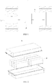
FIG. 1 is a schematic structural diagram of a vehicle according to an embodiment of this application; -
FIG. 2 is a schematic structural exploded view of a battery pack according to an embodiment of this application; -
FIG. 3 is a partial schematic structural diagram of a battery module according to an embodiment of this application; -
FIG. 4 is a schematic structural exploded view of a battery cell according to an embodiment of this application; -
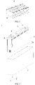
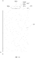
FIG. 5 is a top-view schematic structural diagram of an electrode assembly according to an embodiment of this application; -
FIG. 6 is a side-view schematic structural diagram of an electrode assembly according to an embodiment of this application; -
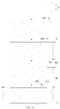
FIG. 7 is a partial side-view schematic structural diagram of an electrode assembly according to an embodiment of this application; -
FIG. 8 is a partial side-view schematic structural diagram of an electrode assembly according to another embodiment of this application; -
FIG. 9 is a partial side-view schematic structural diagram of an electrode assembly according to still another embodiment of this application; -
FIG. 10 is a partial side-view schematic structural diagram of an electrode assembly according to still another embodiment of this application; -
FIG. 11 is a partial side-view schematic structural diagram of an electrode assembly according to still another embodiment of this application; -
FIG. 12 is a partial side-view schematic structural diagram of an electrode assembly according to yet another embodiment of this application; -
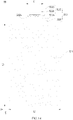
FIG. 13 is a partial top-view schematic structural diagram of an electrode assembly according to an embodiment of this application; -
FIG. 14 is a partial top-view schematic structural diagram of an electrode assembly according to another embodiment of this application; -
FIG. 15 is a schematic diagram of a method for manufacturing an electrode assembly according to an embodiment of this application; -
FIG. 16 is a partial schematic structural diagram of an electrode plate according to an embodiment of this application; and -
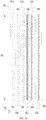
FIG. 17 is a schematic structural diagram of a device for manufacturing an electrode assembly according to an embodiment of this application. - The drawings are not drawn to scale.
- 1. vehicle; 1a. motor; 1b. controller; 10. battery; 11. first shell; 12. second shell; 20. battery module; 30. battery cell; 31. housing; 32. electrode assembly; 32a. electrode body; 321. electrode plate; 3211. main portion; 3211a. metal substrate; 3211b. active material layer; 3212. protruding portion; 32121. body portion; 32121a. fuse portion; 32121b. partitioning groove; 32122. conductive piece; 32122a. first connecting portion; 32122b. second connecting portion; 322. separator; 323. protection layer; 33. end cap; 34. electrode terminal; 35. connector adapter; 40. first sheet of material; 41. first part; 42. second part; 50. second sheet of material; 100. manufacturing device; 101. first material processing apparatus; 102. coating apparatus; 103. second material processing apparatus; 104. material removing apparatus; 105. forming apparatus; X. length direction; Y. width direction; Z. thickness direction.
- The following gives a more detailed description of implementations of this application with reference to drawings and embodiments. The detailed description of the following embodiments and the accompanying drawings are intended to exemplarily describe the principles of this application, but not to limit the scope of this application. Therefore, this application is not limited to the described embodiments.
- In the description of this application, unless otherwise specified, "a plurality of' means at least two in number; the terms such as "upper", "lower", "left", "right", "inner", and "outer" indicating a direction or a position relationship are merely intended for ease or brevity of description of this application, but do not indicate or imply that the mentioned apparatus or component is necessarily located in the specified direction or constructed or operated in the specified direction. Therefore, such terms are not to be understood as a limitation on this application. In addition, the terms "first", "second", and "third" are merely intended for descriptive purposes, but are not intended to indicate or imply relative importance. "Perpendicular" is not exactly perpendicular, but within an error tolerance range. "Parallel" is not exactly parallel, but within an error tolerance range.
- The directional terms appearing in the following description indicate the directions shown in the drawings, but are not intended to limit specific structures in this application. In the description of this application, unless otherwise expressly specified, the terms "mount", "concatenate", and "connect" are understood in a broad sense. For example, a "connection" may be a fixed connection, a detachable connection, or an integrated connection, and may be a direct connection or an indirect connection implemented through an intermediary. A person of ordinary skill in the art can understand the specific meanings of the terms in this application according to specific situations.
- After finding the problem of severe heat emission of a tab, the applicant carries out research and analysis on a battery cell. The applicant finds that, due to increasingly higher requirements on an energy density of a battery, considering that a structure of a battery cell needs to meet requirements on a space occupancy rate, the structure of the battery cell needs to be made into a strip-shaped flat structure, so that an electrode body of an electrode assembly is elongated into a strip-shaped flat structure. The tab extends from an end face of the electrode body. However, the tab extending from the end face of the electrode body incurs a problem of an insufficient current-carrying capacity, thereby leading to the problem of severe heat emission of the tab.
- Based on the foregoing problem found by the applicant, the applicant improves the structure of the battery cell. Embodiments of this application are described below.
- For a better understanding of this application, the following describes embodiments of this application with reference to
FIG. 1 to FIG. 17 . - An embodiment of this application provides an electrical apparatus that uses a
battery 10 as a power supply. The electrical apparatus may be, but is not limited to, a vehicle, a ship, or an aircraft. Referring toFIG. 1 , an embodiment of this application provides avehicle 1. Thevehicle 1 may be an oil-fueled vehicle, a natural gas vehicle, or a new energy vehicle. The new energy vehicle may be a battery electric vehicle, a hybrid electric vehicle, or a range-extended electric vehicle, or the like. In an embodiment of this application, thevehicle 1 may include a motor 1a, acontroller 1b, and abattery 10. Thecontroller 1b is configured to control thebattery 10 to supply power to the motor 1a. The motor 1a is connected to wheels of the vehicle through a transmission mechanism to drive thevehicle 1 to run. Thebattery 10 may be used as a drive power supply of thevehicle 1, and provide driving motive power for thevehicle 1 in place of or partially in place of oil or natural gas. In an example, thebattery 10 may be disposed at the bottom, front, or rear of thevehicle 1. Thebattery 10 may be configured to electrically power thevehicle 1. In an example, thebattery 10 may serve as an operating power supply of thevehicle 1 to power a circuit system of thevehicle 1. In an example, thebattery 10 may be configured to meet operating power usage requirements of thevehicle 1 that is being started, navigated, or running. - Referring to
FIG. 2 , thebattery 10 may include at least twobattery modules 20. In some optional embodiments, thebattery 10 further includes a box. Thebattery modules 20 are disposed in the box. The at least twobattery modules 20 are arranged in the box. The type of the box is not limited. The box may be in a frame shape, a disk shape, a cassette shape, or the like. In an example, the box includes a first shell 11 configured to accommodate thebattery modules 20, and a second shell 12 configured to fit the first shell 11. The first shell 11 fits the second shell 12 to form an accommodation portion configured to accommodate thebattery modules 20. - To meet different power usage requirements, each of the
battery modules 20 may include one ormore battery cells 30. Referring toFIG. 3 , a plurality ofbattery cells 30 may be connected in series, in parallel, or in both series and in parallel to form a battery module, and then a plurality ofbattery modules 20 may be connected in series, in parallel, or in both series and parallel to form a battery. The connecting in both series and parallel means a combination of series connection and parallel connection. In an example, the battery may include a plurality ofbattery cells 30. The plurality ofbattery cells 30 may be connected in series, in parallel, or in both series and parallel. The plurality ofbattery cells 30 may be directly disposed in the box. In other words, the plurality ofbattery cells 30 may directly form thebattery 10, or form thebattery modules 20 that are then used to form thebattery 10. Thebattery cells 30 include, but are not limited to, a lithium-ion secondary battery, a lithium-ion primary battery, a lithium-sulfur battery, a sodium-lithium-ion battery, or a magnesium-ion battery. - When a
battery cell 30 according to this embodiment of this application is applied to thevehicle 1, a width of thebattery cell 30 is the same as the height of thevehicle 1. As limited by space in a height direction of thevehicle 1, the width of thebattery cell 30 is also strictly limited. Therefore, when a capacity of thebattery cell 30 needs to be increased, the increase of the width of thebattery cell 30 is not unlimited, and the length of thebattery cell 30 can be increased. - Referring to
FIG. 4 , thebattery cell 30 according to an embodiment of this application includes ahousing 31 and anelectrode assembly 32 disposed in thehousing 31. Thehousing 31 in this embodiment of this application is a rectangular structure or another shape. Thehousing 31 includes an internal space for accommodating theelectrode assembly 32 and an electrolytic solution, and an opening that is in communication with the internal space. Thehousing 31 may be made of a material such as aluminum, aluminum alloy, or plastic. Theelectrode assembly 32 is a core member for thebattery cell 30 to implement functions of charging and discharging. - The
battery cell 30 according to this embodiment of this application further includes anend cap 33,electrode terminals 34, and aconnector adapter 35. Theend cap 33 is connected to thehousing 31 to seal the opening of thehousing 31. In an example, theend cap 33 may be connected to thehousing 31 by welding. Theelectrode terminals 34 are disposed on theend cap 33. The shape of theelectrode terminals 34 may be circular or rectangular, without being limited herein. Anelectrode terminal 34 is electrically connected to theelectrode assembly 32 by theconnector adapter 35. At least twobattery cells 30 may be connected in series, in parallel, or in both series and parallel by theirrespective electrode terminals 34. - The
electrode assembly 32 according to this embodiment of this application includes anelectrode body 32a. Theelectrode assembly 32 possesses a length, a width and a thickness that are preset. Here, the length means the size of theelectrode body 32a along a length direction X of the electrode body, the width means the size of theelectrode body 32a along a width direction Y of the electrode body, and the thickness means the size of theelectrode body 32a along a thickness direction Z of the electrode body. The length direction X, the width direction Y, and the thickness direction Z are perpendicular to each other. - Referring to
FIG. 4 to FIG. 6 , theelectrode body 32a according to this embodiment of this application may include anelectrode plate 321. In an example, theelectrode plate 321 may be a positive electrode plate. In this case, theelectrode body 32a may include one or more positive electrode plates. In an example, theelectrode plate 321 may be a negative electrode plate. In this case, theelectrode body 32a may include one or more negative electrode plates. When theelectrode body 32a includes a positive electrode plate and a negative electrode plate, the positive electrode plate and the negative electrode plate may be stacked along the thickness direction Z, so that the formedelectrode assembly 32 is a stacked structure. Alternatively, the positive electrode plate and the negative electrode plate may be wound to form theelectrode assembly 32. Twoadjacent electrode plates 321 are of opposite polarities. Therefore, the twoadjacent electrode plates 321 may be separated by aseparator 322. Theseparator 322 is an insulator located between the twoelectrode plates 321 of opposite polarities. - Referring to
FIG. 6 andFIG. 7 , eachelectrode plate 321 according to this embodiment of this application includes amain portion 3211 and at least one protrudingportion 3212. The protrudingportion 3212 protrudes from themain portion 3211 along the length direction X of theelectrode body 32a. In an embodiment in which theelectrode plates 321 are stacked, the protrudingportions 3212 of a same polarity may be stacked along the thickness direction Z. Themain portions 3211 are stacked along the thickness direction Z to form theelectrode body 32a. Theconnector adapter 35 is electrically connected to the protrudingportion 3212. In an example, theconnector adapter 35 is welded to the protrudingportion 3212 by means of laser welding or ultrasonic welding, for example. - The
main portion 3211 includes ametal substrate 3211a and anactive material layer 3211b. At least a part of a surface of themetal substrate 3211a is coated with theactive material layer 3211b. That is, the surface of themetal substrate 3211a may be fully or partly overlaid with theactive material layer 3211b. In an example, when themetal substrate 3211a is an aluminum foil, theactive material layer 3211b may include a ternary material, lithium manganese oxide, or lithium iron phosphate. When themetal substrate 3211a is a copper foil, theactive material layer 3211b may include graphite or silicon. The protrudingportion 3212 is connected to themetal substrate 3211a, and the protrudingportion 3212 protrudes from themetal substrate 3211a along the length direction X of theelectrode body 32a. Along the thickness direction Z of theelectrode body 32a, the size of at least a part of the protrudingportion 3212 is greater than the size of themetal substrate 3211a, thereby increasing the cross-sectional area of the protrudingportion 3212, helping to reduce the resistance of the protrudingportion 3212 and increase an overall heat capacity of the protrudingportion 3212, and in turn, improving the current-carrying capacity of the protrudingportion 3212. The heat capacity means the amount of heat necessary to raise the temperature of a given material by 1 degree. - The
electrode assembly 32 according to this embodiment of this application includes at least oneelectrode plate 321. Theelectrode plate 321 includes amain portion 3211 and a protrudingportion 3212. Themain portion 3211 includes ametal substrate 3211a and anactive material layer 3211b. The protrudingportion 3212 protrudes from themetal substrate 3211a along the length direction X of theelectrode assembly 32. The protrudingportion 3212 is connected to themetal substrate 3211a. Along the thickness direction Z of theelectrode body 32a, the size of at least a part of the protrudingportion 3212 is greater than the size of themetal substrate 3211a. Therefore, the protrudingportion 3212 possesses a relatively large cross-sectional area, so as to achieve a low resistance of the protrudingportion 3212. In addition, due to a high heat capacity of the protrudingportion 3212, the protrudingportion 3212 achieves a relatively high current-carrying capacity. In this way, for a strip-shapedelectrode assembly 32 of which the size in the length direction X is greater than the size in the width direction Y, theelectrode assembly 32 according to this embodiment of this application effectively solves the problem of an insufficient current-carrying capacity of the protrudingportion 3212 of the strip-shapedelectrode assembly 32, and alleviates excessively rapid temperature rise of the protrudingportion 3212 during charging or discharging of theelectrode assembly 32. In addition, heat dissipation performance of the protrudingportion 3212 is improved, thereby reducing a possibility of severe heat emission of the protrudingportion 3212. This can effectively improve the charging and discharging efficiency of the battery, and can reduce overheating risks of the battery during charging or discharging and improve safety of battery in use. - In some embodiments, along the thickness direction Z of the
electrode body 32a, anactive material layer 3211b may be applied onto two opposite surfaces of themetal substrate 3211a. In an example, themetal substrate 3211a is a whole sheet of material. That is, themetal substrate 3211a is an integrally formed structure. - In some embodiments, referring to
FIG. 8 , the protrudingportion 3212 includes abody portion 32121 and aconductive piece 32122. Theconnector adapter 35 may be electrically connected to thebody portion 32121 of the protrudingportion 3212. Thebody portion 32121 and themetal substrate 3211a are made of a same material and are integrally disposed. In an example, both the material of themetal substrate 3211a and the material of thebody portion 32121 are aluminum or copper. That thebody portion 32121 and themetal substrate 3211a are made of the same material and integrally disposed can increase strength of connection between thebody portion 32121 and themetal substrate 3211a, and also improve current-carrying performance between thebody portion 32121 and themetal substrate 3211a. - In some optional embodiments, along the thickness direction Z of the
electrode body 32a, the size of at least a part of thebody portion 32121 is greater than the size of themetal substrate 3211a. That is, the size of the entirety or a part of thebody portion 32121 is greater than the size of themetal substrate 3211a. Therefore, thebody portion 32121 possesses a relatively large cross-sectional area, thereby helping to reduce the resistance of the body portion. In this way, thebody portion 32121 achieves a relatively high current-carrying capacity. - In some embodiments, along the thickness direction Z of the
electrode body 32a, theconductive piece 32122 and thebody portion 32121 are stacked. In an example, at least a part of theconductive piece 32122 may be connected to thebody portion 32121 by welding, for example, by means of laser welding or ultrasonic welding. Theconnector adapter 35 may be electrically connected to the protrudingportion 3212. An electrical current can be conducted out of or into theelectrode assembly 32 through thebody portion 32121, theconductive piece 32122, and theconnector adapter 35, thereby effectively improving electrical conduction performance of theelectrode assembly 32 and overall current-carrying capacity of theelectrode assembly 32. In an example, theconductive piece 32122 may be a sheet structure. - In some optional embodiments, along the thickness direction Z of the
electrode body 32a, a sum of the size of theconductive piece 32122 and the size of thebody portion 32121 is greater than the size of themetal substrate 3211a. Therefore, the protrudingportion 3212 possesses a relatively large cross-sectional area, thereby helping to further reduce the resistance of the protrudingportion 3212. In this way, the protrudingportion 3212 achieves a relatively high current-carrying capacity. - In some optional embodiments, along the thickness direction Z of the
electrode body 32a, the size of thebody portion 32121 is equal to the size of themetal substrate 3211a. That is, the size of the entirety of thebody portion 32121 is equal to the size of themetal substrate 3211a. Along the thickness direction Z of theelectrode body 32a, the surface of thebody portion 32121 may keep flush with the surface of themetal substrate 3211a. In a processing and manufacturing process in which thebody portion 32121 and themetal substrate 3211a are integrally formed, the thickness of thebody portion 32121 is the same as the thickness of themetal substrate 3211a, thereby reducing the processing difficulty of thebody portion 32121 and themetal substrate 3211a, and in turn, reducing the processing cost. In an example, along the thickness direction Z of theelectrode body 32a, the size of theconductive piece 32122 is less than or equal to the size of themetal substrate 3211a, but the sum of the size of theconductive piece 32122 and the size of thebody portion 32121 is greater than the size of themetal substrate 3211a. - In some embodiments, the
body portion 32121, themetal substrate 3211a, and theconductive piece 32122 are made of the same material. Thebody portion 32121, themetal substrate 3211a, and theconductive piece 32122 are of equal resistivity. In an example, thebody portion 32121, themetal substrate 3211a, and theconductive piece 32122 may be made of an aluminum material or a copper material. When theelectrode plate 321 is a positive electrode plate, thebody portion 32121, themetal substrate 3211a, and theconductive piece 32122 may be made of an aluminum material. When theelectrode plate 321 is a negative electrode plate, thebody portion 32121, themetal substrate 3211a, and theconductive piece 32122 may be made of a copper material. - In some embodiments, the
conductive piece 32122 and thebody portion 32121 are made of different materials, and the resistivity of theconductive piece 32122 is less than the resistivity of thebody portion 32121. The resistivity is a physical quantity used for denoting resistance characteristics of various substances. The resistance of a conductor that is 1 meter in length and 1 square meter in cross-sectional area and that is made of a given material is numerically equal to the resistivity of this material. Compared with thebody portion 32121, theconductive piece 32122 with a low resistivity possesses a high current-carrying capacity, thereby helping to further reduce the resistance of the protrudingportion 3212 and improving the current-carrying capacity of the protrudingportion 3212. For example, theconductive piece 32122 is made of a copper material, and thebody portion 32121 is made of an aluminum material. - In some embodiments, the
conductive piece 32122 is connected to thebody portion 32121. An end that is of theconductive piece 32122 and that is away from theactive material layer 3211b is flush with an end that is of thebody portion 32121 and that is away from theactive material layer 3211b. A region that is of theconductive piece 32122 and that overlaps thebody portion 32121 along the thickness direction Z is configured to electrically connect to an external part. In this embodiment of this application, the region that is of theconductive piece 32122 and that overlaps thebody portion 32121 along the thickness direction Z is configured to electrically connect to aconnector adapter 35. When the protrudingportion 3212 is electrically connected to theconnector adapter 35, theconductive piece 32122 and thebody portion 32121 can be electrically connected to theconnector adapter 35 concurrently. In an example, theconductive piece 32122 and thebody portion 32121 are welded to theconnector adapter 35 concurrently. - In some embodiments, referring to
FIG. 9 , theconductive piece 32122 includes a first connectingportion 32122a and a second connectingportion 32122b. The first connectingportion 32122a is configured to connect thebody portion 32121. In an example, the first connectingportion 32122a is connected to thebody portion 32121 by welding. The second connectingportion 32122b protrudes from the end that is of thebody portion 32121 and that is away from theactive material layer 3211b. The second connectingportion 32122b is configured to electrically connect to an external part. In this embodiment of this application, the second connectingportion 32122b is configured to electrically connect to theconnector adapter 35. The electrical connection between the second connectingportion 32122b and theadapter member 35 helps to reduce a stacking thickness of a connection region between the second connectingportion 32122b and theconnector adapter 35. In this way, when the second connectingportion 32122b is connected to theconnector adapter 35 by welding, the electrical connection helps to reduce the difficulty of welding and reduce the possibility of a rosin joint caused between the second connectingportion 32122b and theconnector adapter 35 by poor welding, where the rosin joint adversely affects the current-carrying capacity between the second connectingportion 32122b and theconnector adapter 35. - In some optional embodiments, along the thickness direction Z of the
electrode body 32a, the size of the second connectingportion 32122b is greater than or equal to the size of thebody portion 32121. For example, the sum of the size of the second connectingportion 32122b and the size of thebody portion 32121 is greater than the size of themetal substrate 3211a. - In some embodiments, referring to
FIG. 10 , theconductive piece 32122 is two in number. Along the thickness direction Z of theelectrode body 32a, the twoconductive pieces 32122 are connected to two surfaces of thebody portion 32121 respectively. One surface of thebody portion 32121 is connected to oneconductive piece 32122. The disposition of the twoconductive pieces 32122 and thebody portion 32121 further increases the cross-sectional area of the protrudingportion 3212 and helps to further reduce the resistance of the protrudingportion 3212, so that the protrudingportion 3212 achieves a relatively high current-carrying capacity. - In some optional embodiments, referring to
FIG. 10 , the end that is of eachconductive piece 32122 among the twoconductive pieces 32122 and that is away from theactive material layer 3211b is flush with the end that is of thebody portion 32121 and that is away from theactive material layer 3211b. A region that is of the twoconductive pieces 32122 and that overlaps thebody portion 32121 along the thickness direction Z is configured to electrically connect to an external part. In this embodiment of this application, the region that is of the twoconductive pieces 32122 and that overlaps thebody portion 32121 along the thickness direction Z is configured to electrically connect to aconnector adapter 35. When the protrudingportion 3212 is electrically connected to theconnector adapter 35, the twoconductive pieces 32122 and thebody portion 32121 can be electrically connected to theconnector adapter 35 concurrently. - In some optional embodiments, referring to
FIG. 11 , each of the twoconductive pieces 32122 includes a first connectingportion 32122a and a second connectingportion 32122b. The first connectingportion 32122a of eachconductive piece 32122 is configured to connect thebody portion 32121. The second connectingportion 32122b of eachconductive piece 32122 protrudes from the end that is of thebody portion 32121 and that is away from theactive material layer 3211b. In addition, the second connectingportion 32122b of eachconductive piece 32122 is configured to electrically connect to an external part. In this embodiment of this application, the second connectingportion 32122b of eachconductive piece 32122 is configured to electrically connect to theconnector adapter 35. - In some optional embodiments, the sum of the sizes of the second connecting
portions 32122b of the twoconductive pieces 32122 along the thickness direction Z is greater than or equal to the size of thebody portion 32121 along the thickness direction Z. In this way, the cross-sectional area of the second connectingportions 32122b of the twoconductive pieces 32122 configured to electrically connect to theconnector adapter 35 is greater than or equal to the cross-sectional area of thebody portion 32121, thereby effectively ensuring a relatively high current-carrying capacity of the second connectingportions 32122b of the twoconductive pieces 32122, reducing the possibility that the second connectingportions 32122b of the twoconductive pieces 32122 become portions of a low current-carrying capacity, and in turn, ensuring a high current-carrying capacity of the entire protrudingportion 3212. - In some embodiments, referring to
FIG. 12 , aprotection layer 323 is disposed at a root portion that is of thebody portion 32121 and that is close to theactive material layer 3211b. Theconductive piece 32122 may be connected to thebody portion 32121 by welding. A weld region between theconductive piece 32122 and thebody portion 32121 is spaced apart from theprotection layer 323. During assembling of thebattery cell 30, due to a relatively small thickness of thebody portion 32121, thebody portion 32121 under a force is prone to bend and deform and be pressed into a position between twoadjacent electrode plates 321 to result in short-circuit risks. The root region of thebody portion 32121 is at the highest risk of bending and deformation. Therefore, theprotection layer 323 disposed at the root portion of thebody portion 32121 can serve a protective purpose. Even if thebody portion 32121 is bent and pressed into a position between twoadjacent electrode plates 321, theprotection layer 323 can still effectively separate the twoelectrode plates 321 to reduce short-circuit risks and improve safety of the battery. In an example, the material of theprotection layer 323 may be an insulative material such as one or more of aluminum oxide, magnesium oxide, titanium dioxide, zirconium oxide, silicon dioxide, silicon carbide, boron carbide, calcium carbonate, aluminum silicate, calcium silicate, potassium titanate, or barium sulfate. Theprotection layer 323 may be bonded to thebody portion 32121 by using a binder. The binder includes one or more of polyvinylidene difluoride, polyacrylonitrile, polyacrylic acid, polyacrylate, polyacrylic acid-acrylate, polyacrylonitrile-acrylic acid, or polyacrylonitrile-acrylate. Theprotection layer 323 may be anactive material layer 3211b instead. In coating themetal substrate 3211a of anelectrode plate 321 with theactive material layer 3211b, the root portion of thebody portion 32121 may be coated with theactive material layer 3211b concurrently to form theprotection layer 323. - In some embodiments, referring to
FIG. 13 , thebody portion 32121 includes afuse portion 32121a. Theconductive piece 32122 is connected to thefuse portion 32121a of thebody portion 32121 by welding. In a case that a fuse structure is disposed on theconnector adapter 35, because the fuse structure is far away from a heat emission region, the heat transfer to the fuse structure is delayed. Therefore, the fuse structure is not easily blown in time, thereby adversely affecting the safety of the battery. Compared with the fuse structure disposed on theconnector adapter 35, thefuse portion 32121a disposed at thebody portion 32121 can be close to the heat emission region, thereby helping to shorten the time of heat transfer to thefuse portion 32121a and ensure timely blowing of thefuse portion 32121a, so as to cut off the electrical connection between the protrudingportion 3212 and theconnector adapter 35 and ensure the safety of the battery. - In some optional embodiments, referring to
FIG. 13 , the end that is of thebody portion 32121 and that is away from theelectrode plate 321 includes apartitioning groove 32121b. Thepartitioning groove 32121b partitions the end of thebody portion 32121 so that the end forms a plurality offuse portions 32121a. There is apartitioning groove 32121b between twoadjacent fuse portions 32121a. - In some optional embodiments, referring to
FIG. 14 , along the width direction Y of theelectrode body 32a, the end that is of thebody portion 32121 and that is away from theelectrode plate 321 decreases in size to form thefuse portion 32121a. In an example, edges and corners of the end of thebody portion 32121 may be trimmed off so that the end of thebody portion 32121 decreases in size to form thefuse portion 32121a. - In some embodiments, referring to
FIG. 14 , the size of the protrudingportion 3212 along the width direction Y of theelectrode body 32a is L1. The size of theelectrode plate 321 along the width direction Y of theelectrode body 32a is L2. L1 and L2 satisfy: 1/3 × L2 ≤ L1 ≤ 3/4 × L2. For example, L1 may be 0.4×L2, 0.5×L2, 0.6×L2, 0.7×L2, or the like. - In some optional embodiments, the size L1 of the protruding
portion 3212 along the width direction Y is 15 millimeters (mm) to 60 mm. - In some optional embodiments, the size of the
electrode plate 321 along the length direction X of theelectrode body 32a is L3. The size of theelectrode plate 321 along the width direction Y of theelectrode body 32a is L2. L3 and the width L2 satisfy: a ratio of L3 to L2 ranges from 4 to 20. For example, the ratio of L3 to L2 is an integer that falls within 4 to 20. Theelectrode assembly 32 according to this embodiment of this application includes the protrudingportion 3212 of a high current-carrying capacity. Therefore, the length of theelectrode plate 321 can be increased to a greater extent, and a relatively wide range of a length-to-width ratio can be achieved, thereby helping to increase the energy density of the battery. In addition, fast charging of the battery can be implemented and the battery is not prone to overheating, thereby improving the safety of the battery in use. - In some optional embodiments, a sum of capacity of the
active material layer 3211b on two surfaces of themetal substrate 3211a is C and is greater than 3 Ah but less than 10 Ah. Theelectrode assembly 32 according to this embodiment of this application includes the protrudingportion 3212 of a high current-carrying capacity. Therefore, the capacity of theelectrode plate 321 can be increased to a greater extent, thereby helping to increase the energy density of the battery. In addition, fast charging of the battery can be implemented and the battery is not prone to overheating, thereby improving the charging efficiency. - Referring to
FIG. 15 , an embodiment of this application further provides a method for manufacturing anelectrode assembly 32, including: - providing a first sheet of
material 40, where the first sheet ofmaterial 40 includes afirst part 41 and asecond part 42; - a coating step, that is, coating a surface of the
first part 41 with anactive material layer 3211b; - providing a second sheet of
material 50, and connecting the second sheet ofmaterial 50 to thesecond part 42; - a material removing step, that is, removing a part of material from the second sheet of
material 50 and thesecond part 42 to form anelectrode plate 321 that includes amain portion 3211 and at least one protrudingportion 3212, where themain portion 3211 includes theactive material layer 3211b and ametal substrate 3211a corresponding to theactive material layer 3211b, a thickness of at least a part of the protrudingportion 3212 connected to themetal substrate 3211a is greater than a thickness of themetal substrate 3211a, the protrudingportion 3212 includes abody portion 32121 and aconductive piece 32122 connected to thebody portion 32121, a remainder of thesecond part 42 forms thebody portion 32121, and a remainder of the second sheet ofmaterial 50 forms theconductive piece 32122; and - a forming step, that is, winding or stacking the
electrode plate 321 to form anelectrode assembly 32, where the protrudingportion 3212 protrudes from themetal substrate 3211a along a length direction of theelectrode assembly 32. - In an embodiment, the
electrode plate 321 includes a protrudingportion 3212. Alternatively, referring toFIG. 16 , theelectrode plate 321 includes at least two protrudingportions 3212. The at least two protrudingportions 3212 are spaced apart. - The
electrode assembly 32 manufactured by using the manufacturing method according to this embodiment of this application includes at least oneelectrode plate 321. Theelectrode plate 321 includes amain portion 3211 and at least one protrudingportion 3212. The protrudingportion 3212 protrudes from themetal substrate 3211a along the length direction X of theelectrode assembly 32. The protrudingportion 3212 is connected to themetal substrate 3211a. Along the thickness direction Z of theelectrode body 32a, the size of at least a part of the protrudingportion 3212 is greater than the size of themetal substrate 3211a. Therefore, the protrudingportion 3212 possesses a relatively large cross-sectional area, so as to achieve a low resistance of the protrudingportion 3212. In addition, due to a high heat capacity of the protrudingportion 3212, the protrudingportion 3212 achieves a relatively high current-carrying capacity. In this way, for a strip-shapedelectrode assembly 32 of which the size in the length direction X is greater than the size in the width direction Y, theelectrode assembly 32 according to this embodiment of this application effectively solves the problem of an insufficient current-carrying capacity of the protrudingportion 3212 of the strip-shapedelectrode assembly 32, and alleviates excessively rapid temperature rise of the protrudingportion 3212 during charging or discharging of theelectrode assembly 32. In addition, heat dissipation performance of the protrudingportion 3212 is improved, thereby reducing a possibility of severe heat emission of the protrudingportion 3212. This can effectively improve the charging and discharging efficiency of the battery, and can reduce overheating risks of the battery during charging or discharging and improve safety of battery in use. - Referring to
FIG. 17 , an embodiment of this application further provides adevice 100 for manufacturing anelectrode assembly 32, including: - a first
material processing apparatus 101, configured to provide a first sheet ofmaterial 40, where the first sheet ofmaterial 40 includes afirst part 41 and asecond part 42; - a
coating apparatus 102, configured to coat a surface of thefirst part 41 with anactive material layer 3211b; - a second
material processing apparatus 103, configured to provide a second sheet ofmaterial 50, and connect the second sheet ofmaterial 50 to thesecond part 42; - a
material removing apparatus 104, configured to remove a part of material from the second sheet ofmaterial 50 and thesecond part 42 to form anelectrode plate 321 that includes amain portion 3211 and at least one protrudingportion 3212, where themain portion 3211 includes theactive material layer 3211b and ametal substrate 3211a corresponding to theactive material layer 3211b, a thickness of at least a part of the protrudingportion 3212 connected to themetal substrate 3211a is greater than a thickness of themetal substrate 3211a, the protrudingportion 3212 includes abody portion 32121 and aconductive piece 32122 connected to thebody portion 32121, a remainder of thesecond part 42 forms thebody portion 32121, and a remainder of the second sheet ofmaterial 50 forms theconductive piece 32122; and - a forming
apparatus 105, configured to wind or stack theelectrode plate 321 to form anelectrode assembly 32, where the protrudingportion 3212 protrudes from themetal substrate 3211a along a length direction of theelectrode assembly 32. - In some embodiments, the
material removing apparatus 104 includes a cutter. The cutter is configured to cut the second sheet ofmaterial 50 and thesecond part 42 along a preset trail to remove a part of material from the second sheet ofmaterial 50 and thesecond part 42. - Although this application has been described with reference to exemplary embodiments, various improvements may be made to the embodiments without departing from the scope of this application, and the components of this application may be replaced with equivalents. Particularly, to the extent that no structural conflict exists, various technical features mentioned in various embodiments can be combined in any manner. This application is not limited to the specific embodiments disclosed herein, but includes all technical solutions falling within the scope of the claims.
Claims (24)
- An electrode assembly, comprising:an electrode plate, comprising a main portion and at least one protruding portion, wherein the main portion comprises a metal substrate and an active material layer coated on a surface of the metal substrate, the protruding portion is connected to the metal substrate, and the metal substrate protrudes along a length direction of the electrode assembly, whereinalong a thickness direction of the electrode assembly, a size of at least a part of the protruding portion is greater than a size of the metal substrate.
- The electrode assembly according to claim 1, wherein the protruding portion and the metal substrate are made of a same material and integrally disposed.
- The electrode assembly according to claim 1 or 2, wherein the protruding portion comprises a body portion and a conductive piece, and the body portion and the conductive piece are stacked in the thickness direction.
- The electrode assembly according to claim 3, wherein, along the thickness direction, a size of the body portion is equal to the size of the metal substrate.
- The electrode assembly according to claim 3 or 4, wherein the body portion, the metal substrate, and the conductive piece are made of a same material.
- The electrode assembly according to claim 3 or 4, wherein the conductive piece and the body portion are made of different materials, and a resistivity of the conductive piece is less than a resistivity of the body portion.
- The electrode assembly according to any one of claims 3 to 6, wherein an end that is of the conductive piece and that is away from the active material layer is flush with an end that is of the body portion and that is away from the active material layer, and an overlap region between the conductive piece and the body portion along the thickness direction is configured to implement electrical connection to an external part.
- The electrode assembly according to any one of claims 3 to 6, wherein the conductive piece comprises a first connecting portion and a second connecting portion, the first connecting portion is configured to connect the body portion, the second connecting portion protrudes from an end that is of the body portion and that is away from the active material layer, and the second connecting portion is configured to implement electrical connection to an external part.
- The electrode assembly according to claim 8, wherein, along the thickness direction, a size of the second connecting portion is greater than or equal to a size of the body portion.
- The electrode assembly according to claim 8, wherein the conductive piece is two in number, and the two conductive pieces are connected to two surfaces of the body portion respectively.
- The electrode assembly according to claim 10, wherein, along the thickness direction, a sum of sizes of the second connecting portions of the two conductive pieces is greater than or equal to a size of the body portion.
- The electrode assembly according to any one of claims 3 to 11, wherein the body portion is welded to the conductive piece.
- The electrode assembly according to claim 12, wherein, a protection layer is disposed at a root portion that is of the body portion and that is close to the active material layer, and a weld region between the conductive piece and the body portion is spaced apart from the protection layer.
- The electrode assembly according to any one of claims 3 to 13, wherein the body portion comprises a fuse portion.
- The electrode assembly according to any one of claims 1 to 14, wherein the electrode assembly comprises at least two electrode plates, and the at least two electrode plates are stacked along the thickness direction.
- The electrode assembly according to claim 15, wherein a size of the protruding portion along a width direction of the electrode assembly is L1, a size of each of the electrode plates along the width direction is L2, and L1 and L2 satisfy: 1/3 × L2 ≤ L1 ≤ 3/4 × L2.
- The electrode assembly according to claim 16, wherein the size L1 of the protruding portion along the width direction is 15 mm to 60 mm.
- The electrode assembly according to claim 15, wherein a size of each of the electrode plates along the length direction of the electrode assembly is L3, a size of each of the electrode plates along a width direction of the electrode assembly is L2, and L3 and L2 satisfy: a ratio of L3 to L2 ranges from 4 to 20.
- The electrode assembly according to any one of claims 15 to 18, wherein a sum of capacity of the active material layer on two surfaces of the metal substrate is C and is greater than 3 Ah but less than 10 Ah.
- A battery cell, comprising the electrode assembly according to any one of claims 1 to 19.
- A battery, comprising the battery cell according to claim 20.
- An electrical apparatus, comprising the battery according to claim 21, wherein the battery is configured to provide electrical energy.
- A method for manufacturing an electrode assembly, comprising:providing a first sheet of material, wherein the first sheet of material comprises a first part and a second part;a coating step, that is, coating a surface of the first part with an active material layer;providing a second sheet of material, and connecting the second sheet of material to the second part;a material removing step, that is, removing a part of material from the second sheet of material and the second part to form an electrode plate that comprises a main portion and at least one protruding portion, wherein the main portion comprises the active material layer and a metal substrate corresponding to the active material layer, a thickness of at least a part of the protruding portion connected to the metal substrate is greater than a thickness of the metal substrate, the protruding portion comprises a body portion and a conductive piece connected to the body portion, a remainder of the second part forms the body portion, and a remainder of the second sheet of material forms the conductive piece; anda forming step, that is, winding or stacking the electrode plate to form an electrode assembly, wherein the protruding portion protrudes from the metal substrate along a length direction of the electrode assembly.
- A device for manufacturing an electrode assembly, comprising:a first material processing apparatus, configured to provide a first sheet of material, wherein the first sheet of material comprises a first part and a second part;a coating apparatus, configured to coat a surface of the first part with an active material layer;a second material processing apparatus, configured to provide a second sheet of material, and connect the second sheet of material to the second part;a material removing apparatus, configured to remove a part of material from the second sheet of material and the second part to form an electrode plate that comprises a main portion and at least one protruding portion, wherein the main portion comprises the active material layer and a metal substrate corresponding to the active material layer, a thickness of at least a part of the protruding portion connected to the metal substrate is greater than a thickness of the metal substrate, the protruding portion comprises a body portion and a conductive piece connected to the body portion, a remainder of the second part forms the body portion, and a remainder of the second sheet of material forms the conductive piece; anda forming apparatus, configured to wind or stack the electrode plate to form an electrode assembly, wherein the protruding portion protrudes from the metal substrate along a length direction of the electrode assembly.
Applications Claiming Priority (1)
| Application Number | Priority Date | Filing Date | Title |
|---|---|---|---|
| PCT/CN2020/122245 WO2022082446A1 (en) | 2020-10-20 | 2020-10-20 | Electrode assembly, battery cell, battery, electric apparatus, and manufacturing method and device |
Publications (2)
| Publication Number | Publication Date |
|---|---|
| EP4084207A1 true EP4084207A1 (en) | 2022-11-02 |
| EP4084207A4 EP4084207A4 (en) | 2023-05-10 |
Family
ID=81291317
Family Applications (1)
| Application Number | Title | Priority Date | Filing Date |
|---|---|---|---|
| EP20958029.9A Pending EP4084207A4 (en) | 2020-10-20 | 2020-10-20 | ELECTRODE ASSEMBLY, BATTERY CELL, BATTERY, ELECTRICAL APPARATUS, AND METHOD AND DEVICE FOR MAKING |
Country Status (6)
| Country | Link |
|---|---|
| US (1) | US12021269B2 (en) |
| EP (1) | EP4084207A4 (en) |
| JP (1) | JP7450731B2 (en) |
| KR (1) | KR102751794B1 (en) |
| CN (1) | CN115066803B (en) |
| WO (1) | WO2022082446A1 (en) |
Cited By (2)
| Publication number | Priority date | Publication date | Assignee | Title |
|---|---|---|---|---|
| EP4579928A4 (en) * | 2022-09-29 | 2025-11-19 | Ningde Amperex Technology Ltd | ELECTROCHEMICAL DEVICE AND ELECTRICAL DEVICE |
| EP4579927A4 (en) * | 2022-09-29 | 2025-11-19 | Ningde Amperex Technology Ltd | ELECTROCHEMICAL DEVICE AND ELECTRICAL DEVICE |
Families Citing this family (2)
| Publication number | Priority date | Publication date | Assignee | Title |
|---|---|---|---|---|
| CN115842093B (en) * | 2022-05-07 | 2024-01-05 | 宁德时代新能源科技股份有限公司 | Pole piece, manufacturing method, electrode assembly, manufacturing method, battery cell and battery |
| CN217740571U (en) * | 2022-07-21 | 2022-11-04 | 宁德时代新能源科技股份有限公司 | Pole piece, electrode component, battery monomer, battery and power consumption device |
Family Cites Families (24)
| Publication number | Priority date | Publication date | Assignee | Title |
|---|---|---|---|---|
| US6641027B2 (en) | 2001-12-18 | 2003-11-04 | Ngk Spark Plug Co., Ltd. | Method of connecting electric leads to battery tabs |
| US7179562B2 (en) * | 2003-02-14 | 2007-02-20 | Quallion Llc | Battery electrode assembly and fabrication method therefor |
| JP4658467B2 (en) * | 2003-11-12 | 2011-03-23 | 三菱重工業株式会社 | Electrode for lithium secondary battery and lithium secondary battery |
| JP4687006B2 (en) | 2004-05-26 | 2011-05-25 | トヨタ自動車株式会社 | Power storage device |
| JP5021961B2 (en) | 2006-06-16 | 2012-09-12 | Necエナジーデバイス株式会社 | Laminated battery and manufacturing method thereof |
| CN201383529Y (en) * | 2009-04-15 | 2010-01-13 | 深圳市中凯兴能源科技有限公司 | Position-staggered tail-wrapping structure for lithium battery |
| JP2012146852A (en) * | 2011-01-13 | 2012-08-02 | Tokyo Electron Ltd | Electrode manufacturing device, electrode manufacturing method, program, and computer storage medium |
| CN202308207U (en) | 2011-10-27 | 2012-07-04 | 深圳市比克电池有限公司 | Multi-pole-piece winding-type cell and square flexible-package lithium battery |
| KR20150007741A (en) * | 2013-07-12 | 2015-01-21 | 삼성에스디아이 주식회사 | rechargeable battery |
| KR101709560B1 (en) | 2013-09-27 | 2017-02-23 | 주식회사 엘지화학 | Secondary Battery with Electrode Tab Having Low Resistance |
| KR102044404B1 (en) * | 2017-03-16 | 2019-11-14 | 주식회사 리베스트 | Flexible battery assembly having strengthening tab joint structure between electrode tab and electrode lead |
| KR101978700B1 (en) * | 2017-12-12 | 2019-05-15 | 주식회사 아모라이프사이언스 | heating patch and heating device for skin care including the same |
| CN108428849B (en) | 2017-11-22 | 2024-01-16 | 宁德时代新能源科技股份有限公司 | Electrode member, electrode assembly, and rechargeable battery |
| KR102270867B1 (en) * | 2017-12-07 | 2021-07-01 | 주식회사 엘지에너지솔루션 | Electrode, method for manufacturing the same, electrode assembly and secondary battery |
| CN208507818U (en) * | 2018-06-29 | 2019-02-15 | 宁德时代新能源科技股份有限公司 | Secondary cell and its pole piece |
| CN209087968U (en) * | 2018-08-02 | 2019-07-09 | 宁德时代新能源科技股份有限公司 | Electrode member, electrode assembly and secondary cell |
| CN208955108U (en) * | 2018-10-11 | 2019-06-07 | 宁德时代新能源科技股份有限公司 | Secondary cell and its electrode member |
| CN110660956B (en) * | 2018-10-17 | 2024-10-18 | 宁德时代新能源科技股份有限公司 | Secondary battery and electrode member thereof |
| CN111148382A (en) * | 2018-11-03 | 2020-05-12 | 扬州正扬电力科技有限公司 | Electrical control cabinet with rain and snow prevention function |
| CN210926141U (en) | 2019-11-26 | 2020-07-03 | 惠州锂威新能源科技有限公司 | Novel lug, electrode plate and lithium ion battery |
| CN211182349U (en) | 2019-12-11 | 2020-08-04 | 曙鹏科技(深圳)有限公司 | Tab, lithium ion battery and electronic product |
| CN111682156B (en) | 2020-06-19 | 2023-06-30 | 珠海冠宇电池股份有限公司 | Battery and its preparation method and electronic product |
| CN213782158U (en) * | 2020-07-10 | 2021-07-23 | 宁德时代新能源科技股份有限公司 | Batteries, devices including batteries and apparatus for making batteries |
| CN112018321B (en) * | 2020-10-19 | 2021-04-06 | 江苏时代新能源科技有限公司 | Battery, electrical device, method and apparatus for preparing battery |
-
2020
- 2020-10-20 KR KR1020227025642A patent/KR102751794B1/en active Active
- 2020-10-20 JP JP2022543114A patent/JP7450731B2/en active Active
- 2020-10-20 EP EP20958029.9A patent/EP4084207A4/en active Pending
- 2020-10-20 CN CN202080095842.3A patent/CN115066803B/en active Active
- 2020-10-20 WO PCT/CN2020/122245 patent/WO2022082446A1/en not_active Ceased
-
2022
- 2022-07-27 US US17/815,216 patent/US12021269B2/en active Active
Cited By (2)
| Publication number | Priority date | Publication date | Assignee | Title |
|---|---|---|---|---|
| EP4579928A4 (en) * | 2022-09-29 | 2025-11-19 | Ningde Amperex Technology Ltd | ELECTROCHEMICAL DEVICE AND ELECTRICAL DEVICE |
| EP4579927A4 (en) * | 2022-09-29 | 2025-11-19 | Ningde Amperex Technology Ltd | ELECTROCHEMICAL DEVICE AND ELECTRICAL DEVICE |
Also Published As
| Publication number | Publication date |
|---|---|
| US20220367985A1 (en) | 2022-11-17 |
| KR20220119699A (en) | 2022-08-30 |
| US12021269B2 (en) | 2024-06-25 |
| EP4084207A4 (en) | 2023-05-10 |
| CN115066803B (en) | 2024-01-09 |
| JP2023510580A (en) | 2023-03-14 |
| CN115066803A (en) | 2022-09-16 |
| JP7450731B2 (en) | 2024-03-15 |
| KR102751794B1 (en) | 2025-01-07 |
| WO2022082446A1 (en) | 2022-04-28 |
Similar Documents
| Publication | Publication Date | Title |
|---|---|---|
| US12021269B2 (en) | Electrode assembly, battery cell, battery, electrical apparatus, and manufacturing method and device | |
| WO2022088824A1 (en) | Electrode assembly, battery cell, battery and power-consuming apparatus | |
| EP4106087A1 (en) | Battery cell, battery, power-consuming device, and manufacturing method and device for battery | |
| CN115064847B (en) | Adapter member, battery cell, battery, and power consumption device | |
| CN216213945U (en) | Battery cells, batteries and electrical devices | |
| CN117199736B (en) | Battery cells, batteries and electrical devices | |
| CN221508426U (en) | Electrode assembly, battery cell, battery and electrical device | |
| CN216250906U (en) | Battery cell, battery and consumer | |
| WO2022170493A1 (en) | Battery, electric apparatus, and battery manufacturing method and device | |
| US12506155B2 (en) | Electrode assembly, battery cell, battery, and method and device for manufacturing electrode assembly | |
| CN117199644B (en) | Battery cell, battery and electricity utilization device | |
| JP7761637B2 (en) | Electrode assembly, battery cell, battery, and method and device for manufacturing the electrode assembly | |
| CN218939956U (en) | Pole piece, electrode assembly, battery cell, battery and electrical equipment | |
| CN115066802A (en) | Battery cell, battery and power consumption device | |
| WO2022170492A1 (en) | Battery, power apparatus, and battery manufacturing method and device | |
| CN117134051A (en) | Battery cells, batteries and electrical devices | |
| CN217768626U (en) | Battery cell, battery and power consumption device | |
| US20250192398A1 (en) | Electrode assembly, battery cell, battery, and electrical device | |
| WO2024016447A1 (en) | Current collector, electrode sheet, battery cell, hot-pressing mold, battery, and electric device | |
| CN221102351U (en) | Battery monomer, battery and electric equipment | |
| WO2025175715A1 (en) | Battery, electric device and energy storage device | |
| CN218827692U (en) | Connectors, battery cells, batteries and electrical devices | |
| CN220774658U (en) | Connecting piece, battery module, battery, electric equipment and energy storage equipment | |
| CN220672722U (en) | Battery cell, battery and electricity utilization device | |
| EP4618208A1 (en) | Secondary battery, battery module including the secondary battery, battery pack including the battery module, and vehicle including the battery pack |
Legal Events
| Date | Code | Title | Description |
|---|---|---|---|
| STAA | Information on the status of an ep patent application or granted ep patent |
Free format text: STATUS: THE INTERNATIONAL PUBLICATION HAS BEEN MADE |
|
| PUAI | Public reference made under article 153(3) epc to a published international application that has entered the european phase |
Free format text: ORIGINAL CODE: 0009012 |
|
| STAA | Information on the status of an ep patent application or granted ep patent |
Free format text: STATUS: REQUEST FOR EXAMINATION WAS MADE |
|
| 17P | Request for examination filed |
Effective date: 20220729 |
|
| AK | Designated contracting states |
Kind code of ref document: A1 Designated state(s): AL AT BE BG CH CY CZ DE DK EE ES FI FR GB GR HR HU IE IS IT LI LT LU LV MC MK MT NL NO PL PT RO RS SE SI SK SM TR |
|
| A4 | Supplementary search report drawn up and despatched |
Effective date: 20230414 |
|
| RIC1 | Information provided on ipc code assigned before grant |
Ipc: H01M 10/052 20100101ALN20230406BHEP Ipc: H01M 50/536 20210101ALI20230406BHEP Ipc: H01M 50/534 20210101ALI20230406BHEP Ipc: H01M 10/0587 20100101ALI20230406BHEP Ipc: H01M 10/0585 20100101ALI20230406BHEP Ipc: H01M 10/04 20060101ALI20230406BHEP Ipc: H01M 4/139 20100101ALI20230406BHEP Ipc: H01M 4/04 20060101ALI20230406BHEP Ipc: H01M 50/538 20210101ALI20230406BHEP Ipc: H01M 50/533 20210101AFI20230406BHEP |
|
| DAV | Request for validation of the european patent (deleted) | ||
| DAX | Request for extension of the european patent (deleted) | ||
| STAA | Information on the status of an ep patent application or granted ep patent |
Free format text: STATUS: EXAMINATION IS IN PROGRESS |
|
| 17Q | First examination report despatched |
Effective date: 20240320 |
|
| RAP1 | Party data changed (applicant data changed or rights of an application transferred) |
Owner name: CONTEMPORARY AMPEREX TECHNOLOGY(HONG KONG) LIMITED |