EP4084191A1 - Battery module including gas breaking structure - Google Patents
Battery module including gas breaking structure Download PDFInfo
- Publication number
- EP4084191A1 EP4084191A1 EP21780259.4A EP21780259A EP4084191A1 EP 4084191 A1 EP4084191 A1 EP 4084191A1 EP 21780259 A EP21780259 A EP 21780259A EP 4084191 A1 EP4084191 A1 EP 4084191A1
- Authority
- EP
- European Patent Office
- Prior art keywords
- battery
- duct
- battery module
- side plate
- battery cell
- Prior art date
- Legal status (The legal status is an assumption and is not a legal conclusion. Google has not performed a legal analysis and makes no representation as to the accuracy of the status listed.)
- Granted
Links
Images


Classifications
-
- H—ELECTRICITY
- H01—ELECTRIC ELEMENTS
- H01M—PROCESSES OR MEANS, e.g. BATTERIES, FOR THE DIRECT CONVERSION OF CHEMICAL ENERGY INTO ELECTRICAL ENERGY
- H01M50/00—Constructional details or processes of manufacture of the non-active parts of electrochemical cells other than fuel cells, e.g. hybrid cells
- H01M50/20—Mountings; Secondary casings or frames; Racks, modules or packs; Suspension devices; Shock absorbers; Transport or carrying devices; Holders
- H01M50/204—Racks, modules or packs for multiple batteries or multiple cells
- H01M50/207—Racks, modules or packs for multiple batteries or multiple cells characterised by their shape
- H01M50/209—Racks, modules or packs for multiple batteries or multiple cells characterised by their shape adapted for prismatic or rectangular cells
-
- H—ELECTRICITY
- H01—ELECTRIC ELEMENTS
- H01M—PROCESSES OR MEANS, e.g. BATTERIES, FOR THE DIRECT CONVERSION OF CHEMICAL ENERGY INTO ELECTRICAL ENERGY
- H01M10/00—Secondary cells; Manufacture thereof
- H01M10/60—Heating or cooling; Temperature control
- H01M10/65—Means for temperature control structurally associated with the cells
- H01M10/656—Means for temperature control structurally associated with the cells characterised by the type of heat-exchange fluid
- H01M10/6561—Gases
- H01M10/6566—Means within the gas flow to guide the flow around one or more cells, e.g. manifolds, baffles or other barriers
-
- A—HUMAN NECESSITIES
- A62—LIFE-SAVING; FIRE-FIGHTING
- A62C—FIRE-FIGHTING
- A62C2/00—Fire prevention or containment
- A62C2/06—Physical fire-barriers
-
- A—HUMAN NECESSITIES
- A62—LIFE-SAVING; FIRE-FIGHTING
- A62C—FIRE-FIGHTING
- A62C3/00—Fire prevention, containment or extinguishing specially adapted for particular objects or places
- A62C3/16—Fire prevention, containment or extinguishing specially adapted for particular objects or places in electrical installations, e.g. cableways
-
- H—ELECTRICITY
- H01—ELECTRIC ELEMENTS
- H01M—PROCESSES OR MEANS, e.g. BATTERIES, FOR THE DIRECT CONVERSION OF CHEMICAL ENERGY INTO ELECTRICAL ENERGY
- H01M10/00—Secondary cells; Manufacture thereof
- H01M10/60—Heating or cooling; Temperature control
- H01M10/61—Types of temperature control
- H01M10/613—Cooling or keeping cold
-
- H—ELECTRICITY
- H01—ELECTRIC ELEMENTS
- H01M—PROCESSES OR MEANS, e.g. BATTERIES, FOR THE DIRECT CONVERSION OF CHEMICAL ENERGY INTO ELECTRICAL ENERGY
- H01M10/00—Secondary cells; Manufacture thereof
- H01M10/60—Heating or cooling; Temperature control
- H01M10/64—Heating or cooling; Temperature control characterised by the shape of the cells
- H01M10/647—Prismatic or flat cells, e.g. pouch cells
-
- H—ELECTRICITY
- H01—ELECTRIC ELEMENTS
- H01M—PROCESSES OR MEANS, e.g. BATTERIES, FOR THE DIRECT CONVERSION OF CHEMICAL ENERGY INTO ELECTRICAL ENERGY
- H01M10/00—Secondary cells; Manufacture thereof
- H01M10/60—Heating or cooling; Temperature control
- H01M10/65—Means for temperature control structurally associated with the cells
- H01M10/655—Solid structures for heat exchange or heat conduction
- H01M10/6556—Solid parts with flow channel passages or pipes for heat exchange
-
- H—ELECTRICITY
- H01—ELECTRIC ELEMENTS
- H01M—PROCESSES OR MEANS, e.g. BATTERIES, FOR THE DIRECT CONVERSION OF CHEMICAL ENERGY INTO ELECTRICAL ENERGY
- H01M10/00—Secondary cells; Manufacture thereof
- H01M10/60—Heating or cooling; Temperature control
- H01M10/65—Means for temperature control structurally associated with the cells
- H01M10/656—Means for temperature control structurally associated with the cells characterised by the type of heat-exchange fluid
- H01M10/6561—Gases
- H01M10/6563—Gases with forced flow, e.g. by blowers
-
- H—ELECTRICITY
- H01—ELECTRIC ELEMENTS
- H01M—PROCESSES OR MEANS, e.g. BATTERIES, FOR THE DIRECT CONVERSION OF CHEMICAL ENERGY INTO ELECTRICAL ENERGY
- H01M50/00—Constructional details or processes of manufacture of the non-active parts of electrochemical cells other than fuel cells, e.g. hybrid cells
- H01M50/10—Primary casings; Jackets or wrappings
- H01M50/14—Primary casings; Jackets or wrappings for protecting against damage caused by external factors
- H01M50/143—Fireproof; Explosion-proof
-
- H—ELECTRICITY
- H01—ELECTRIC ELEMENTS
- H01M—PROCESSES OR MEANS, e.g. BATTERIES, FOR THE DIRECT CONVERSION OF CHEMICAL ENERGY INTO ELECTRICAL ENERGY
- H01M50/00—Constructional details or processes of manufacture of the non-active parts of electrochemical cells other than fuel cells, e.g. hybrid cells
- H01M50/20—Mountings; Secondary casings or frames; Racks, modules or packs; Suspension devices; Shock absorbers; Transport or carrying devices; Holders
- H01M50/258—Modular batteries; Casings provided with means for assembling
-
- H—ELECTRICITY
- H01—ELECTRIC ELEMENTS
- H01M—PROCESSES OR MEANS, e.g. BATTERIES, FOR THE DIRECT CONVERSION OF CHEMICAL ENERGY INTO ELECTRICAL ENERGY
- H01M50/00—Constructional details or processes of manufacture of the non-active parts of electrochemical cells other than fuel cells, e.g. hybrid cells
- H01M50/30—Arrangements for facilitating escape of gases
- H01M50/35—Gas exhaust passages comprising elongated, tortuous or labyrinth-shaped exhaust passages
- H01M50/367—Internal gas exhaust passages forming part of the battery cover or case; Double cover vent systems
-
- H—ELECTRICITY
- H01—ELECTRIC ELEMENTS
- H01M—PROCESSES OR MEANS, e.g. BATTERIES, FOR THE DIRECT CONVERSION OF CHEMICAL ENERGY INTO ELECTRICAL ENERGY
- H01M50/00—Constructional details or processes of manufacture of the non-active parts of electrochemical cells other than fuel cells, e.g. hybrid cells
- H01M50/30—Arrangements for facilitating escape of gases
- H01M50/375—Vent means sensitive to or responsive to temperature
-
- H—ELECTRICITY
- H01—ELECTRIC ELEMENTS
- H01M—PROCESSES OR MEANS, e.g. BATTERIES, FOR THE DIRECT CONVERSION OF CHEMICAL ENERGY INTO ELECTRICAL ENERGY
- H01M50/00—Constructional details or processes of manufacture of the non-active parts of electrochemical cells other than fuel cells, e.g. hybrid cells
- H01M50/30—Arrangements for facilitating escape of gases
- H01M50/383—Flame arresting or ignition-preventing means
-
- H—ELECTRICITY
- H01—ELECTRIC ELEMENTS
- H01M—PROCESSES OR MEANS, e.g. BATTERIES, FOR THE DIRECT CONVERSION OF CHEMICAL ENERGY INTO ELECTRICAL ENERGY
- H01M50/00—Constructional details or processes of manufacture of the non-active parts of electrochemical cells other than fuel cells, e.g. hybrid cells
- H01M50/50—Current conducting connections for cells or batteries
- H01M50/502—Interconnectors for connecting terminals of adjacent batteries; Interconnectors for connecting cells outside a battery casing
- H01M50/505—Interconnectors for connecting terminals of adjacent batteries; Interconnectors for connecting cells outside a battery casing comprising a single busbar
-
- H—ELECTRICITY
- H01—ELECTRIC ELEMENTS
- H01M—PROCESSES OR MEANS, e.g. BATTERIES, FOR THE DIRECT CONVERSION OF CHEMICAL ENERGY INTO ELECTRICAL ENERGY
- H01M2200/00—Safety devices for primary or secondary batteries
-
- Y—GENERAL TAGGING OF NEW TECHNOLOGICAL DEVELOPMENTS; GENERAL TAGGING OF CROSS-SECTIONAL TECHNOLOGIES SPANNING OVER SEVERAL SECTIONS OF THE IPC; TECHNICAL SUBJECTS COVERED BY FORMER USPC CROSS-REFERENCE ART COLLECTIONS [XRACs] AND DIGESTS
- Y02—TECHNOLOGIES OR APPLICATIONS FOR MITIGATION OR ADAPTATION AGAINST CLIMATE CHANGE
- Y02E—REDUCTION OF GREENHOUSE GAS [GHG] EMISSIONS, RELATED TO ENERGY GENERATION, TRANSMISSION OR DISTRIBUTION
- Y02E60/00—Enabling technologies; Technologies with a potential or indirect contribution to GHG emissions mitigation
- Y02E60/10—Energy storage using batteries
Definitions
- the present invention relates to a battery module including a gas cutoff structure, and more particularly to a battery module including a gas cutoff structure disposed in a duct that communicates with battery cell module assemblies such that, in the case in which fire breaks out in a specific battery cell module assembly, flames are prevented from spreading to battery cell module assemblies adjacent thereto.
- a secondary battery has different configurations depending on output and capacity required in fields or products to which the secondary battery is applied.
- small mobile devices such as a mobile phone, a digital camera, and a laptop computer
- a single battery cell or a small battery pack including about ten battery cells per device so as to correspond to a small, light, and thin trend of corresponding products.
- medium or large devices such as an electric bicycle, an electric vehicle, and a hybrid electric vehicle, use a medium or large battery pack including a plurality battery cells electrically connected to each other due to necessity of high output and large capacity.
- the size and weight of a battery pack are directly related to the accommodation space and output of a corresponding medium or large device, and therefore manufacturers are trying to manufacture small and light battery packs.
- an electrode terminal region of a battery cell for secondary batteries is a region upon which heat is concentrated, and may serve as a path through which flames are discharged outside when fire breaks out in the battery cell due to a high-temperature phenomenon of the battery cell.
- a battery pack is configured to have an open structure in which a busbar for electrical connection between battery cells or battery modules received in the battery pack and a connector for connection with an external system are coupled to the battery pack and in which a heat dissipation fan configured to discharge heat from the battery pack is installed in the battery pack.
- the battery pack has a structure in which it is difficult for movement of a material between the inside and the outside of the battery pack to be completely cut off, as described above, flames generated in the battery pack may be easily transfer to a region adjacent thereto, and air including oxygen may be continuously supplied into the battery pack from outside the battery pack, whereby the state in which fire breaks out may continue.
- Patent Document 1 discloses a battery pack including a thermal expansion member configured to prevent external air from being introduced into a battery pack case when fire breaks out in a battery module
- Patent Document 2 discloses a battery pack including a structure configured to be deformed by overheating at the time of battery abnormality so as to close an opening of a battery pack case.
- Patent Document 1 and Patent Document 2 do not suggest a structure capable of preventing flames generated in a battery pack from spreading in the battery pack.
- a battery module including a structure capable of preventing introduction of external air when fire breaks out in a battery pack and cutting off movement of gas such that flames in a battery cell module assembly that has caught fire do not spread to battery cell module assemblies adjacent thereto.
- the present invention has been made in view of the above problems, and it is an object of the present invention to provide a battery module including a gas cutoff structure capable of circulating air in order to prevent an increase in temperature of the battery module and cutting off movement of air and flames to prevent consecutive breakout of fire when fire breaks out in the battery module.
- a battery module includes a plurality of battery cell module assemblies, each of the plurality of battery cell module assemblies including battery cells arranged in tight contact with each other, a side plate electrically connected to electrode leads of the plurality of battery cell module assemblies, a duct disposed outside the side plate, and a gas cutoff structure disposed in the duct, wherein the plurality of battery cell module assemblies is disposed so as to have a space therebetween.
- the side plate may have an open structure such that the plurality of battery cell module assemblies communicate with the duct.
- Each of the plurality of battery cell module assemblies may be configured to have a structure in which a plurality of battery cells is received in a housing, and an open surface of the housing may be coupled to the side plate.
- the side plate may have an integrated structure that covers the entire side surface of the battery module in a direction in which the electrode leads of the plurality of battery cell module assemblies protrude.
- the gas cutoff structure may be disposed in the duct at a position corresponding to the space.
- the side plate may include a first side plate and a second side plate located respectively at opposite ends of the plurality of battery cell module assemblies in an overall length direction thereof, and a first duct may be located outside the first side plate and a second duct may be located outside the second side plate.
- the battery module may be configured to have a structure in which a refrigerant is introduced through a first end of the first duct, passes through the plurality of battery cell module assemblies, and is discharged through a second end of the second duct.
- the gas cutoff structure may include a cutoff membrane configured to open and close the duct and a fixing portion configured to fix the cutoff membrane, and, when heat is generated in the battery module, the fixing portion is melted, whereby the fixed state of the cutoff membrane is released, the cutoff membrane may be rotated such that the flow of gas through the duct is cut off.
- the gas cutoff structure may include a cutoff membrane configured to open and close the duct, a temperature fuse connected to a first end of the cutoff membrane, and an elastic body connected to a second end of the cutoff membrane opposite the first end of the cutoff membrane, and, when heat is generated in the battery module, the temperature fuse is cut off, the cutoff membrane may be rotated by elastic force of the elastic body, whereby the flow of gas through the duct may be cut off.
- the cutoff membrane may include two blades extending from a central axis for rotation in opposite directions, and the blades may have a straight shape or a spiral shape when viewed from one end of the central axis.
- An inner surface of the duct may be provided with a projecting portion configured to stop rotation of the cutoff membrane.
- the projecting portion may be formed by a portion of the duct being depressed inwards or may be configured to have a structure in which a protrusion is attached to the inner surface of the duct.
- the present invention provides a battery pack including the battery module.
- a battery module according to the present invention is configured such that battery cell module assemblies are received in independent housings, and therefore a duct may be provided outside a side plate as a path for air circulation.
- air introduced through the duct is circulated so as to pass through the battery cell module assemblies and to then be discharged, whereby it is possible to cool the battery module.
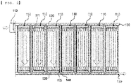
- FIG. 1 is a perspective view of a battery module according to the present invention
- FIG. 2 is a plan view of the battery module of FIG. 1 in the state in which the upper surface of a battery cell module assembly is removed therefrom.
- the battery module 100 is configured such that a plurality of battery cell module assemblies 110 is disposed so as to have a space 115 therebetween and battery cells 111 are arranged in each of the battery cell module assemblies 110 in tight contact with each other.
- Each of the battery cell module assemblies 110 is configured such that a plurality of battery cells 111 is received in a housing, and the battery cell module assemblies are independently disposed in a battery module housing in the state in which the battery cell module assemblies are received in individual housings.
- the present invention includes battery cell module assemblies, each of which uses an independent housing, as described above, it is possible to solve a conventional problem in that the battery cell module assemblies are disposed in the battery module housing in an open state, i.e. in the state in which the battery cell module assemblies are not received in individual housings, whereby flames easily spread when fire breaks out.
- each of the battery cell module assemblies 110 is formed so as to have a mono frame shape, and therefore the housing has a structure that is open in a direction in which electrode leads protrude.
- the battery module is assembled by coupling a side plate 120 to an open surface of the housing including the open structure.
- the side plate 120 electrically connected to the electrode leads of the battery cells 111 includes a first side plate and a second side plate located respectively at opposite ends of the battery cell module assemblies 110 in an overall length direction thereof.
- the side plate 120 is configured to have an integrated structure that covers the entirety of a first surface of the battery cell module assemblies 110 in the direction in which the electrode leads protrude and a first surface of the space 115 defined between the battery cell module assemblies.
- the side plate 120 is configured to have a size capable of covering the entirety of the first surface formed by the plurality of battery cell module assemblies and the space therebetween.
- the battery module according to the present invention is configured such that the battery cell module assemblies are received in individual housings and includes a side plate having an integrated structure, whereby no separate battery module case is necessary.
- a duct 130 configured to allow air to flow therethrough is disposed outside of each of the first side plate and the second side plate.
- a first duct is located outside the first side plate, and a second duct is located outside the second side plate.
- the battery module according to the present invention is configured to have a structure in which air introduced through the duct passes through the battery cell module assemblies and is discharged through the opposite duct. Consequently, the side plate may be configured to have an open structure such that the battery cell module assemblies communicate with the duct in order to circulate air.
- air that functions as a refrigerant is introduced into the battery modules from outside the battery modules through a fan 112 connected to one end of the first duct. As indicated by dotted arrows of FIG. 2 , the air is introduced through a first end of the first duct, passes through the side plate configured to have the open structure, passes through the battery cell module assemblies 110, passes through the opposite side plate configured to have the open structure, and is discharged through a second end of the second duct.
- the side plate may constitute one side surface of the duct 130.
- a separate square-pillar-shaped duct may be disposed outside the side plate, and a structure that communicates with the battery cell module assemblies through the side plate may be formed at one side surface of the duct that overlaps the side plate.
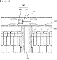
- FIG. 3 is a partial enlarged view of the battery module of FIG. 1
- FIG. 4 is a partial enlarged view showing the state of a gas cutoff structure before operation thereof
- FIG. 5 is a partial enlarged view showing the state in which the gas cutoff structure of FIG. 4 is operated.
- the gas cutoff structure 140 is located in the duct 130. Specifically, the gas cutoff structure 140 is located in the duct 130 at a position corresponding to the space 115 so as to prevent flames from moving between adjacent battery cell module assemblies 110.
- the side plate 120 includes an opening portion 122 formed by cutting and bending a portion of the side plate such that the battery cell module assemblies communicate with the duct 130.
- the shape of the opening portion is not limited to the shape shown in FIGS. 3 to 5 , and the opening portion may be formed as a through-hole or a slit.
- the gas cutoff structure 140 includes a cutoff membrane 142 configured to open and close the duct 130 and a fixing portion 141 configured to fix the cutoff membrane 142.
- FIG. 4 shows the state in which the fixing portion 141 holds the cutoff membrane 142 to fix the cutoff membrane in the case in which the battery module is in a normal state.
- the cutoff membrane 142 is disposed in parallel to a direction in which air flows (indicated by dotted arrows).
- the structure of the fixing portion is not limited to the structure shown in FIG. 4 , and is not particularly restricted as long as the fixing portion is capable of stably holding and fixing the cutoff membrane in a normal state and is capable of being rapidly melted such that the fixed state of the cutoff membrane is released when heat is generated or when fire breaks out.
- FIG. 5 shows the state in which heat is generated in the right-side battery cell module assembly 110, whereby the fixing portion 141 is melted, and therefore the fixed state of the cutoff membrane 142 is released.
- the fixing portion 141 is made of a material that is capable of being melted at high temperature.
- the fixing portion may be made of a polymer resin having a glass transition temperature or a melting point of 300°C or lower.
- gas heated in the right-side battery cell module assembly 110 moves leftwards in the figure
- air introduced into the battery module from outside the battery module through the fan is introduced rightwards in the figure
- the cutoff membrane 142 rotated by the pressure difference between the heated gas and the introduced air is caught by a projecting portion 144 formed on the inner surface of the duct 130, whereby rotation of the cutoff membrane is stopped.
- the flow of the gas that flows in the duct is cut off by the cutoff membrane 142 stopped as described above, whereby it is possible to prevent the heated gas from spreading to battery cell module assemblies adjacent thereto, and it is also possible to prevent external air including oxygen from being introduced into the battery cell module assembly that has caught fire to thus prevent the battery cell module assembly from continuously burning.
- FIG. 6 is a plan view showing a gas cutoff structure according to an embodiment.
- the gas cutoff structure 240 includes a cutoff membrane 242 configured to open and close the duct, a temperature fuse 247 connected to a first end of the cutoff membrane 242, and an elastic body 248 connected to a second end of the cutoff membrane 242 opposite the first end of the cutoff membrane.
- the projecting portion formed on the inner surface of the duct of FIG. 5 may also be formed on the inner surface of the duct of FIG. 6 , and rotation of the cutoff membrane may be stopped by the projecting portion.
- the projecting portion may be formed on the inner surface of the bottom of the duct or may be formed on the inner surface of the side plate.
- FIG. 7 is a plan view showing the shape of the cutoff membrane of the gas cutoff structure.
- the cutoff membrane 342 shown in FIG. 7(a) which is identical in shape to each of the cutoff membranes 142 and 242 shown in FIGS. 5 and 6 , includes two blades 349 extending from a central axis 343 for rotation in opposite directions.
- the blades 349 are formed so as to have a straight shape when viewed from one end of the central axis 343.
- the cutoff membrane 442 shown in FIG. 7(b) includes two blades 449 extending from a central axis 443 for rotation in opposite directions.
- the blades 449 are formed so as to have a spiral shape when viewed from one end of the central axis 443.
- the projecting portion formed on the inner surface of the duct of FIG. 5 may also be formed on the inner surface of the duct of FIG. 7 , and rotation of the cutoff membrane may be stopped by the projecting portion.
- the cutoff membrane is rapidly rotated by the pressure difference in gas that passes through the duct, whereby it is possible to completely cut off the gas that passes through the duct. Consequently, it is possible to prevent spread of flames and heat generated in the battery cell module assemblies and to prevent air outside the battery module from being introduced into the battery module, whereby it is possible to prevent enlargement to large-scale fire.
- a battery module according to the present invention is configured such that battery cell module assemblies are received in independent housings, and therefore a duct may be provided outside a side plate as a path for air circulation.
- air introduced through the duct is circulated so as to pass through the battery cell module assemblies and to then be discharged, whereby it is possible to cool the battery module.
Landscapes
- Chemical & Material Sciences (AREA)
- Chemical Kinetics & Catalysis (AREA)
- Electrochemistry (AREA)
- General Chemical & Material Sciences (AREA)
- Engineering & Computer Science (AREA)
- Manufacturing & Machinery (AREA)
- Health & Medical Sciences (AREA)
- Public Health (AREA)
- Business, Economics & Management (AREA)
- Emergency Management (AREA)
- Battery Mounting, Suspending (AREA)
- Secondary Cells (AREA)
- Gas Exhaust Devices For Batteries (AREA)
Abstract
Description
- This application claims the benefit of priority to
Korean Patent Application No. 2020-0039868 filed on April 1, 2020 - The present invention relates to a battery module including a gas cutoff structure, and more particularly to a battery module including a gas cutoff structure disposed in a duct that communicates with battery cell module assemblies such that, in the case in which fire breaks out in a specific battery cell module assembly, flames are prevented from spreading to battery cell module assemblies adjacent thereto.
- A secondary battery has different configurations depending on output and capacity required in fields or products to which the secondary battery is applied. For example, small mobile devices, such as a mobile phone, a digital camera, and a laptop computer, use a single battery cell or a small battery pack including about ten battery cells per device so as to correspond to a small, light, and thin trend of corresponding products. On the other hand, medium or large devices, such as an electric bicycle, an electric vehicle, and a hybrid electric vehicle, use a medium or large battery pack including a plurality battery cells electrically connected to each other due to necessity of high output and large capacity.
- In general, the size and weight of a battery pack are directly related to the accommodation space and output of a corresponding medium or large device, and therefore manufacturers are trying to manufacture small and light battery packs.
- During charging and discharging of the secondary battery, heat is generated in the secondary battery, whereby the temperature of the secondary battery increases. In the case in which the secondary battery abnormally operates or in the case in which the internal structure of the secondary battery is damaged by external impact, combustion and outbreak of fire may occur in the secondary battery.
- In particular, an electrode terminal region of a battery cell for secondary batteries is a region upon which heat is concentrated, and may serve as a path through which flames are discharged outside when fire breaks out in the battery cell due to a high-temperature phenomenon of the battery cell.
- Meanwhile, in the case in which a plurality of battery cell module assemblies constituting a battery module is disposed in a battery module housing so as to communicate with each other without being individually divided, when fire breaks out in a specific battery cell module assembly, heat and flames may spread to battery cell module assemblies adjacent thereto, whereby fire may be enlarged.
- Also, in many cases, a battery pack is configured to have an open structure in which a busbar for electrical connection between battery cells or battery modules received in the battery pack and a connector for connection with an external system are coupled to the battery pack and in which a heat dissipation fan configured to discharge heat from the battery pack is installed in the battery pack.
- Since the battery pack has a structure in which it is difficult for movement of a material between the inside and the outside of the battery pack to be completely cut off, as described above, flames generated in the battery pack may be easily transfer to a region adjacent thereto, and air including oxygen may be continuously supplied into the battery pack from outside the battery pack, whereby the state in which fire breaks out may continue.
- In connection therewith, Patent Document 1 discloses a battery pack including a thermal expansion member configured to prevent external air from being introduced into a battery pack case when fire breaks out in a battery module, and Patent Document 2 discloses a battery pack including a structure configured to be deformed by overheating at the time of battery abnormality so as to close an opening of a battery pack case.
- However, Patent Document 1 and Patent Document 2 do not suggest a structure capable of preventing flames generated in a battery pack from spreading in the battery pack.
- Therefore, there is an increasing necessity for a battery module including a structure capable of preventing introduction of external air when fire breaks out in a battery pack and cutting off movement of gas such that flames in a battery cell module assembly that has caught fire do not spread to battery cell module assemblies adjacent thereto.
-
- (Patent Document 1)
Japanese Patent Application Publication No. 2015-153616 (2015.08.24 - (Patent Document 2)
Korean Patent Application Publication No. 20413-0089327 (2016.12.01 - The present invention has been made in view of the above problems, and it is an object of the present invention to provide a battery module including a gas cutoff structure capable of circulating air in order to prevent an increase in temperature of the battery module and cutting off movement of air and flames to prevent consecutive breakout of fire when fire breaks out in the battery module.
- In order to accomplish the above object, a battery module according to the present invention includes a plurality of battery cell module assemblies, each of the plurality of battery cell module assemblies including battery cells arranged in tight contact with each other, a side plate electrically connected to electrode leads of the plurality of battery cell module assemblies, a duct disposed outside the side plate, and a gas cutoff structure disposed in the duct, wherein the plurality of battery cell module assemblies is disposed so as to have a space therebetween.
- The side plate may have an open structure such that the plurality of battery cell module assemblies communicate with the duct.
- Each of the plurality of battery cell module assemblies may be configured to have a structure in which a plurality of battery cells is received in a housing, and an open surface of the housing may be coupled to the side plate.
- The side plate may have an integrated structure that covers the entire side surface of the battery module in a direction in which the electrode leads of the plurality of battery cell module assemblies protrude.
- The gas cutoff structure may be disposed in the duct at a position corresponding to the space.
- The side plate may include a first side plate and a second side plate located respectively at opposite ends of the plurality of battery cell module assemblies in an overall length direction thereof, and a first duct may be located outside the first side plate and a second duct may be located outside the second side plate.
- The battery module may be configured to have a structure in which a refrigerant is introduced through a first end of the first duct, passes through the plurality of battery cell module assemblies, and is discharged through a second end of the second duct.
- The gas cutoff structure may include a cutoff membrane configured to open and close the duct and a fixing portion configured to fix the cutoff membrane, and, when heat is generated in the battery module, the fixing portion is melted, whereby the fixed state of the cutoff membrane is released, the cutoff membrane may be rotated such that the flow of gas through the duct is cut off.
- The gas cutoff structure may include a cutoff membrane configured to open and close the duct, a temperature fuse connected to a first end of the cutoff membrane, and an elastic body connected to a second end of the cutoff membrane opposite the first end of the cutoff membrane, and, when heat is generated in the battery module, the temperature fuse is cut off, the cutoff membrane may be rotated by elastic force of the elastic body, whereby the flow of gas through the duct may be cut off.
- The cutoff membrane may include two blades extending from a central axis for rotation in opposite directions, and the blades may have a straight shape or a spiral shape when viewed from one end of the central axis.
- An inner surface of the duct may be provided with a projecting portion configured to stop rotation of the cutoff membrane.
- The projecting portion may be formed by a portion of the duct being depressed inwards or may be configured to have a structure in which a protrusion is attached to the inner surface of the duct.
- In addition, the present invention provides a battery pack including the battery module.
- As is apparent from the above description, a battery module according to the present invention is configured such that battery cell module assemblies are received in independent housings, and therefore a duct may be provided outside a side plate as a path for air circulation.
- Also, in the battery module, air introduced through the duct is circulated so as to pass through the battery cell module assemblies and to then be discharged, whereby it is possible to cool the battery module.
- In addition, it is possible to prevent flames in a specific battery cell module assembly from spreading to battery cell module assemblies adjacent thereto by the provision of a gas cutoff structure disposed in the duct through which the air is circulated.
- In addition, it is possible to reuse the battery module through replacement of the battery cell module assembly that has caught fire.
-
-
FIG. 1 is a perspective view of a battery module according to the present invention. -
FIG. 2 is a plan view of the battery module ofFIG. 1 in the state in which the upper surface of a battery cell module assembly is removed therefrom. -
FIG. 3 is a partial enlarged view of the battery module ofFIG. 1 . -
FIG. 4 is a partial enlarged view showing the state of a gas cutoff structure before operation thereof. -
FIG. 5 is a partial enlarged view showing the state in which the gas cutoff structure ofFIG. 4 is operated. -
FIG. 6 is a plan view showing a gas cutoff structure according to an embodiment. -
FIG. 7 is a plan view showing the shape of a cutoff membrane of the gas cutoff structure. - Now, preferred embodiments of the present invention will be described in detail with reference to the accompanying drawings such that the preferred embodiments of the present invention can be easily implemented by a person having ordinary skill in the art to which the present invention pertains. In describing the principle of operation of the preferred embodiments of the present invention in detail, however, a detailed description of known functions and configurations incorporated herein will be omitted when the same may obscure the subject matter of the present invention.
- In addition, the same reference numbers will be used throughout the drawings to refer to parts that perform similar functions or operations. In the case in which one part is said to be connected to another part in the specification, not only may the one part be directly connected to the other part, but also, the one part may be indirectly connected to the other part via a further part. In addition, that a certain element is included does not mean that other elements are excluded, but means that such elements may be further included unless mentioned otherwise.
- In addition, a description to embody elements through limitation or addition may be applied to all inventions, unless particularly restricted, and does not limit a specific invention.
- Also, in the description of the invention of the present application and the claims, singular forms are intended to include plural forms unless mentioned otherwise.
- Also, in the description of the invention of the present application and the claims, "or" includes "and" unless mentioned otherwise. Therefore, "including A or B" means three cases, namely, the case including A, the case including B, and the case including A and B.
- In addition, all numeric ranges include the lowest value, the highest value, and all intermediate values therebetween unless the context clearly indicates otherwise.
- Hereinafter, embodiments of the present invention will be described in detail with reference to the accompanying drawings.
-
FIG. 1 is a perspective view of a battery module according to the present invention, andFIG. 2 is a plan view of the battery module ofFIG. 1 in the state in which the upper surface of a battery cell module assembly is removed therefrom. - Referring to
FIGS. 1 and2 , thebattery module 100 according to the present invention is configured such that a plurality of batterycell module assemblies 110 is disposed so as to have aspace 115 therebetween andbattery cells 111 are arranged in each of the battery cell module assemblies 110 in tight contact with each other. - Each of the battery
cell module assemblies 110 is configured such that a plurality ofbattery cells 111 is received in a housing, and the battery cell module assemblies are independently disposed in a battery module housing in the state in which the battery cell module assemblies are received in individual housings. - Since the present invention includes battery cell module assemblies, each of which uses an independent housing, as described above, it is possible to solve a conventional problem in that the battery cell module assemblies are disposed in the battery module housing in an open state, i.e. in the state in which the battery cell module assemblies are not received in individual housings, whereby flames easily spread when fire breaks out.
- The housing of each of the battery
cell module assemblies 110 is formed so as to have a mono frame shape, and therefore the housing has a structure that is open in a direction in which electrode leads protrude. The battery module is assembled by coupling aside plate 120 to an open surface of the housing including the open structure. - The
side plate 120 electrically connected to the electrode leads of thebattery cells 111 includes a first side plate and a second side plate located respectively at opposite ends of the batterycell module assemblies 110 in an overall length direction thereof. - The
side plate 120 is configured to have an integrated structure that covers the entirety of a first surface of the batterycell module assemblies 110 in the direction in which the electrode leads protrude and a first surface of thespace 115 defined between the battery cell module assemblies. - That is, the
side plate 120 is configured to have a size capable of covering the entirety of the first surface formed by the plurality of battery cell module assemblies and the space therebetween. - As described above, the battery module according to the present invention is configured such that the battery cell module assemblies are received in individual housings and includes a side plate having an integrated structure, whereby no separate battery module case is necessary.
- A
duct 130 configured to allow air to flow therethrough is disposed outside of each of the first side plate and the second side plate. A first duct is located outside the first side plate, and a second duct is located outside the second side plate. - The battery module according to the present invention is configured to have a structure in which air introduced through the duct passes through the battery cell module assemblies and is discharged through the opposite duct. Consequently, the side plate may be configured to have an open structure such that the battery cell module assemblies communicate with the duct in order to circulate air.
- In a concrete example, air that functions as a refrigerant is introduced into the battery modules from outside the battery modules through a
fan 112 connected to one end of the first duct. As indicated by dotted arrows ofFIG. 2 , the air is introduced through a first end of the first duct, passes through the side plate configured to have the open structure, passes through the batterycell module assemblies 110, passes through the opposite side plate configured to have the open structure, and is discharged through a second end of the second duct. - It is possible to cool the heated battery module through the flow of air described above.
- Meanwhile, in connection with the structure of the duct according to the present invention, the side plate may constitute one side surface of the
duct 130. Alternatively, a separate square-pillar-shaped duct may be disposed outside the side plate, and a structure that communicates with the battery cell module assemblies through the side plate may be formed at one side surface of the duct that overlaps the side plate. -
FIG. 3 is a partial enlarged view of the battery module ofFIG. 1 ,FIG. 4 is a partial enlarged view showing the state of a gas cutoff structure before operation thereof, andFIG. 5 is a partial enlarged view showing the state in which the gas cutoff structure ofFIG. 4 is operated. - Referring to
FIGS. 3 to 5 , thegas cutoff structure 140 is located in theduct 130. Specifically, thegas cutoff structure 140 is located in theduct 130 at a position corresponding to thespace 115 so as to prevent flames from moving between adjacent batterycell module assemblies 110. - The
side plate 120 includes anopening portion 122 formed by cutting and bending a portion of the side plate such that the battery cell module assemblies communicate with theduct 130. - The shape of the opening portion is not limited to the shape shown in
FIGS. 3 to 5 , and the opening portion may be formed as a through-hole or a slit. - The
gas cutoff structure 140 includes acutoff membrane 142 configured to open and close theduct 130 and a fixingportion 141 configured to fix thecutoff membrane 142. -
FIG. 4 shows the state in which the fixingportion 141 holds thecutoff membrane 142 to fix the cutoff membrane in the case in which the battery module is in a normal state. Thecutoff membrane 142 is disposed in parallel to a direction in which air flows (indicated by dotted arrows). - The structure of the fixing portion is not limited to the structure shown in
FIG. 4 , and is not particularly restricted as long as the fixing portion is capable of stably holding and fixing the cutoff membrane in a normal state and is capable of being rapidly melted such that the fixed state of the cutoff membrane is released when heat is generated or when fire breaks out. -
FIG. 5 shows the state in which heat is generated in the right-side batterycell module assembly 110, whereby the fixingportion 141 is melted, and therefore the fixed state of thecutoff membrane 142 is released. The fixingportion 141 is made of a material that is capable of being melted at high temperature. For example, the fixing portion may be made of a polymer resin having a glass transition temperature or a melting point of 300°C or lower. - When the fixing
portion 141 is melted, the fixed state of thecutoff membrane 142 is released, whereby the cutoff membrane is rotated by the flow of gas that flows in the duct. - Specifically, gas heated in the right-side battery
cell module assembly 110 moves leftwards in the figure, air introduced into the battery module from outside the battery module through the fan is introduced rightwards in the figure, and thecutoff membrane 142 rotated by the pressure difference between the heated gas and the introduced air is caught by a projectingportion 144 formed on the inner surface of theduct 130, whereby rotation of the cutoff membrane is stopped. - The flow of the gas that flows in the duct is cut off by the
cutoff membrane 142 stopped as described above, whereby it is possible to prevent the heated gas from spreading to battery cell module assemblies adjacent thereto, and it is also possible to prevent external air including oxygen from being introduced into the battery cell module assembly that has caught fire to thus prevent the battery cell module assembly from continuously burning. -
FIG. 6 is a plan view showing a gas cutoff structure according to an embodiment. - Referring to
FIG. 6 , thegas cutoff structure 240 includes acutoff membrane 242 configured to open and close the duct, atemperature fuse 247 connected to a first end of thecutoff membrane 242, and anelastic body 248 connected to a second end of thecutoff membrane 242 opposite the first end of the cutoff membrane. When heat is generated in the battery module, thetemperature fuse 247 is cut off, and thecutoff membrane 242 is rotated by elastic force of theelastic body 248, whereby the duct is completely clogged. As a result, the flow of gas through the duct is cut off. - As described with reference to
FIG. 5 , therefore, it is possible to prevent the heated gas from spreading to battery cell module assemblies adjacent thereto, and it is also possible to prevent external air including oxygen from being introduced into the battery cell module assembly that has caught fire to thus prevent the battery cell module assembly from continuously burning. - Although omitted from
FIG. 6 , the projecting portion formed on the inner surface of the duct ofFIG. 5 may also be formed on the inner surface of the duct ofFIG. 6 , and rotation of the cutoff membrane may be stopped by the projecting portion. - In addition, although the state in which the projecting portion is formed on the inner surface of the outside part of the duct is shown in
FIG. 5 , the projecting portion may be formed on the inner surface of the bottom of the duct or may be formed on the inner surface of the side plate. -
FIG. 7 is a plan view showing the shape of the cutoff membrane of the gas cutoff structure. - The
cutoff membrane 342 shown inFIG. 7(a) , which is identical in shape to each of thecutoff membranes FIGS. 5 and6 , includes twoblades 349 extending from acentral axis 343 for rotation in opposite directions. Theblades 349 are formed so as to have a straight shape when viewed from one end of thecentral axis 343. - The
cutoff membrane 442 shown inFIG. 7(b) includes twoblades 449 extending from acentral axis 443 for rotation in opposite directions. Theblades 449 are formed so as to have a spiral shape when viewed from one end of thecentral axis 443. - Although omitted from
FIG. 7 , the projecting portion formed on the inner surface of the duct ofFIG. 5 may also be formed on the inner surface of the duct ofFIG. 7 , and rotation of the cutoff membrane may be stopped by the projecting portion. - In the gas cutoff structure according to the present invention, as described above, the cutoff membrane is rapidly rotated by the pressure difference in gas that passes through the duct, whereby it is possible to completely cut off the gas that passes through the duct. Consequently, it is possible to prevent spread of flames and heat generated in the battery cell module assemblies and to prevent air outside the battery module from being introduced into the battery module, whereby it is possible to prevent enlargement to large-scale fire.
- Those skilled in the art to which the present invention pertains will appreciate that various applications and modifications are possible within the category of the present invention based on the above description.
-
- 100:
- Battery module
- 110:
- Battery cell module assembly
- 111:
- Battery cell
- 112:
- Fan
- 115:
- Space
- 120:
- Side plate
- 122:
- Opening portion
- 130:
- Duct
- 140, 240:
- Gas cutoff structures
- 141:
- Fixing portion
- 142, 242, 342, 442:
- Cutoff membranes
- 144:
- Projecting portion
- 247:
- Temperature fuse
- 248:
- Elastic body
- 343, 443:
- Central axes
- 349, 449:
- Blades
- As is apparent from the above description, a battery module according to the present invention is configured such that battery cell module assemblies are received in independent housings, and therefore a duct may be provided outside a side plate as a path for air circulation.
- Also, in the battery module, air introduced through the duct is circulated so as to pass through the battery cell module assemblies and to then be discharged, whereby it is possible to cool the battery module.
- In addition, it is possible to prevent flames in a specific battery cell module assembly from spreading to battery cell module assemblies adjacent thereto by the provision of a gas cutoff structure disposed in the duct through which the air is circulated.
- In addition, it is possible to reuse the battery module through replacement of the battery cell module assembly that has caught fire.
Claims (13)
- A battery module comprising:a plurality of battery cell module assemblies, each of the plurality of battery cell module assemblies comprising battery cells arranged in tight contact with each other;a side plate electrically connected to electrode leads of the plurality of battery cell module assemblies;a duct disposed outside the side plate; anda gas cutoff structure disposed in the duct,wherein the plurality of battery cell module assemblies is disposed so as to have a space therebetween.
- The battery module according to claim 1, wherein the side plate has an open structure such that the plurality of battery cell module assemblies communicate with the duct.
- The battery module according to claim 1, wherein each of the plurality of battery cell module assemblies is configured to have a structure in which a plurality of battery cells is received in a housing, and
wherein an open surface of the housing is coupled to the side plate. - The battery module according to claim 1, wherein the side plate has an integrated structure that covers an entire side surface of the battery module in a direction in which the electrode leads of the plurality of battery cell module assemblies protrude.
- The battery module according to claim 1, wherein the gas cutoff structure is disposed in the duct at a position corresponding to the space.
- The battery module according to claim 1, wherein the side plate comprises a first side plate and a second side plate located respectively at opposite ends of the plurality of battery cell module assemblies in an overall length direction thereof, and
wherein a first duct is located outside the first side plate and a second duct is located outside the second side plate. - The battery module according to claim 6, wherein the battery module is configured to have a structure in which a refrigerant is introduced through a first end of the first duct, passes through the plurality of battery cell module assemblies, and is discharged through a second end of the second duct.
- The battery module according to claim 1, wherein the gas cutoff structure comprises a cutoff membrane configured to open and close the duct and a fixing portion configured to fix the cutoff membrane, and
wherein, when heat is generated in the battery module, the fixing portion is melted, whereby a fixed state of the cutoff membrane is released, the cutoff membrane is rotated such that a flow of gas through the duct is cut off. - The battery module according to claim 1, wherein the gas cutoff structure comprises a cutoff membrane configured to open and close the duct, a temperature fuse connected to a first end of the cutoff membrane, and an elastic body connected to a second end of the cutoff membrane opposite the first end of the cutoff membrane, and
wherein, when heat is generated in the battery module, the temperature fuse is cut off, the cutoff membrane is rotated by elastic force of the elastic body, whereby a flow of gas through the duct is cut off. - The battery module according to claim 8 or 9, wherein the cutoff membrane comprises two blades extending from a central axis for rotation in opposite directions, and
wherein the blades have a straight shape or a spiral shape when viewed from one end of the central axis. - The battery module according to claim 8 or 9, wherein an inner surface of the duct is provided with a projecting portion configured to stop rotation of the cutoff membrane.
- The battery module according to claim 11, wherein the projecting portion is formed by a portion of the duct being depressed inwards or is configured to have a structure in which a protrusion is attached to the inner surface of the duct.
- A battery pack comprising the battery module according to claim 1.
Applications Claiming Priority (2)
| Application Number | Priority Date | Filing Date | Title |
|---|---|---|---|
| KR1020200039868A KR102814566B1 (en) | 2020-04-01 | 2020-04-01 | Battery Module Comprising Gas Barrier Structure |
| PCT/KR2021/002500 WO2021201443A1 (en) | 2020-04-01 | 2021-02-26 | Battery module including gas breaking structure |
Publications (3)
| Publication Number | Publication Date |
|---|---|
| EP4084191A1 true EP4084191A1 (en) | 2022-11-02 |
| EP4084191A4 EP4084191A4 (en) | 2023-08-09 |
| EP4084191B1 EP4084191B1 (en) | 2026-04-01 |
Family
ID=77929105
Family Applications (1)
| Application Number | Title | Priority Date | Filing Date |
|---|---|---|---|
| EP21780259.4A Active EP4084191B1 (en) | 2020-04-01 | 2021-02-26 | Battery module including gas cutoff structure |
Country Status (7)
| Country | Link |
|---|---|
| US (1) | US20230052417A1 (en) |
| EP (1) | EP4084191B1 (en) |
| JP (1) | JP7317233B2 (en) |
| KR (1) | KR102814566B1 (en) |
| CN (1) | CN114982043B (en) |
| AU (1) | AU2021248343A1 (en) |
| WO (1) | WO2021201443A1 (en) |
Families Citing this family (11)
| Publication number | Priority date | Publication date | Assignee | Title |
|---|---|---|---|---|
| US12294108B2 (en) * | 2021-10-18 | 2025-05-06 | Lg Energy Solution, Ltd. | Battery module and battery pack with improved safety |
| KR102920762B1 (en) * | 2021-11-23 | 2026-01-29 | 주식회사 엘지에너지솔루션 | Battery pack with improved safety |
| CN117837011A (en) * | 2021-12-27 | 2024-04-05 | 株式会社Lg新能源 | Battery pack, ESS including the battery pack, and vehicle |
| EP4343946B1 (en) * | 2021-12-27 | 2026-04-01 | LG Energy Solution, Ltd. | Battery pack, and ess and vehicle including the battery pack |
| EP4379937A4 (en) * | 2021-12-27 | 2025-01-29 | LG Energy Solution, Ltd. | BATTERY PACK AND VEHICLE COMPRISING IT |
| US12456775B2 (en) | 2022-08-10 | 2025-10-28 | Lg Energy Solution, Ltd. | Battery pack and vehicle including the same |
| KR102951911B1 (en) * | 2022-09-30 | 2026-04-10 | 주식회사 엘지에너지솔루션 | Battery pack and vehicle including the same |
| KR20250072763A (en) * | 2023-11-17 | 2025-05-26 | 주식회사 엘지에너지솔루션 | Battery pack and Vehicle including the same |
| KR20250091605A (en) * | 2023-12-14 | 2025-06-23 | 주식회사 엘지에너지솔루션 | Device including battery pack |
| KR20250136211A (en) | 2024-03-07 | 2025-09-16 | 주식회사 엘지에너지솔루션 | Battery pack |
| KR20250136045A (en) | 2024-03-07 | 2025-09-16 | 주식회사 엘지에너지솔루션 | Battery pack |
Family Cites Families (22)
| Publication number | Priority date | Publication date | Assignee | Title |
|---|---|---|---|---|
| JP2007179873A (en) * | 2005-12-28 | 2007-07-12 | Showa Aircraft Ind Co Ltd | battery |
| JP5183171B2 (en) * | 2007-11-28 | 2013-04-17 | 三洋電機株式会社 | Battery system |
| JP5507173B2 (en) * | 2009-09-25 | 2014-05-28 | パナソニック株式会社 | Battery module and battery pack using the same |
| JP2011258426A (en) * | 2010-06-09 | 2011-12-22 | Hitachi Vehicle Energy Ltd | Secondary battery pack |
| JP5619154B2 (en) * | 2010-11-30 | 2014-11-05 | パナソニック株式会社 | Battery pack |
| KR101348218B1 (en) | 2012-02-02 | 2014-01-07 | 주식회사 엘지화학 | Secondary Battery Including Heat Shrinking Member |
| JP5993209B2 (en) * | 2012-05-24 | 2016-09-14 | タイガースポリマー株式会社 | Battery cooling structure |
| KR102050310B1 (en) * | 2012-11-06 | 2019-11-29 | 에스케이이노베이션 주식회사 | Battery pack |
| JP5761164B2 (en) * | 2012-11-30 | 2015-08-12 | トヨタ自動車株式会社 | Assembled battery |
| KR102034816B1 (en) * | 2012-12-20 | 2019-10-22 | 에스케이이노베이션 주식회사 | Battery Module Assembly |
| US8663824B1 (en) * | 2013-01-26 | 2014-03-04 | Tesla Motors, Inc. | Battery pack exhaust nozzle utilizing an SMA seal retainer |
| JP2015076216A (en) * | 2013-10-08 | 2015-04-20 | 日産自動車株式会社 | Battery module |
| FR3016473B1 (en) * | 2014-01-13 | 2017-10-13 | Schneider Electric Ind Sas | UNIPOLAR CUT-OFF BLOCK AND CUTTING DEVICE COMPRISING SUCH A BLOCK |
| JP2015153616A (en) | 2014-02-14 | 2015-08-24 | 株式会社オートネットワーク技術研究所 | Battery pack |
| KR101649154B1 (en) * | 2014-02-24 | 2016-08-18 | 엘지전자 주식회사 | Battery Pack |
| KR20150136223A (en) * | 2014-05-26 | 2015-12-07 | 삼성에스디아이 주식회사 | Rechargeable battery |
| US20160059196A1 (en) * | 2014-09-03 | 2016-03-03 | Edward Milton McWhorter | Simplex electric circuit |
| JP6256397B2 (en) * | 2015-03-23 | 2018-01-10 | トヨタ自動車株式会社 | Battery pack |
| JP6365884B2 (en) * | 2015-04-14 | 2018-08-01 | 豊田合成株式会社 | Assembled battery |
| JP6861045B2 (en) * | 2017-02-09 | 2021-04-21 | 株式会社エンビジョンAescジャパン | Assembled battery, battery pack, manufacturing method of assembled battery and manufacturing method of battery pack |
| KR102158912B1 (en) | 2018-10-05 | 2020-09-23 | 안창규 | Apparatus for adjusting the angle of chair seat |
| CN209183604U (en) * | 2018-12-27 | 2019-07-30 | 宁德时代新能源科技股份有限公司 | battery box |
-
2020
- 2020-04-01 KR KR1020200039868A patent/KR102814566B1/en active Active
-
2021
- 2021-02-26 WO PCT/KR2021/002500 patent/WO2021201443A1/en not_active Ceased
- 2021-02-26 CN CN202180009135.2A patent/CN114982043B/en active Active
- 2021-02-26 AU AU2021248343A patent/AU2021248343A1/en active Pending
- 2021-02-26 JP JP2022530287A patent/JP7317233B2/en active Active
- 2021-02-26 US US17/794,396 patent/US20230052417A1/en active Pending
- 2021-02-26 EP EP21780259.4A patent/EP4084191B1/en active Active
Also Published As
| Publication number | Publication date |
|---|---|
| WO2021201443A1 (en) | 2021-10-07 |
| EP4084191A4 (en) | 2023-08-09 |
| AU2021248343A1 (en) | 2022-09-01 |
| KR20210122559A (en) | 2021-10-12 |
| KR102814566B1 (en) | 2025-05-29 |
| CN114982043B (en) | 2025-12-02 |
| CN114982043A (en) | 2022-08-30 |
| EP4084191B1 (en) | 2026-04-01 |
| JP2023505029A (en) | 2023-02-08 |
| US20230052417A1 (en) | 2023-02-16 |
| JP7317233B2 (en) | 2023-07-28 |
Similar Documents
| Publication | Publication Date | Title |
|---|---|---|
| EP4084191B1 (en) | Battery module including gas cutoff structure | |
| CN112673518B (en) | Battery module and method for manufacturing battery module | |
| US11398659B2 (en) | Battery block | |
| EP2058895B1 (en) | Battery module | |
| EP2284928B1 (en) | Battery pack with improved heat dissipation efficiency | |
| CN110600654B (en) | Rechargeable battery and battery module | |
| CN106953059B (en) | bus bar | |
| EP3316344B1 (en) | Battery module | |
| CN101295777B (en) | battery module | |
| EP4213293A2 (en) | Battery pack | |
| US20050140338A1 (en) | Lead member and secondary battery module with the same | |
| US20150044519A1 (en) | Battery pack thermal management system | |
| EP4184667B1 (en) | Battery module, and battery pack and vehicle comprising same | |
| CN113939948A (en) | Battery module including unit frame | |
| EP4318770A1 (en) | Power supply device | |
| CN116711131A (en) | Battery module and battery pack containing the battery module | |
| JP7771223B2 (en) | secondary battery | |
| JP4876338B2 (en) | Battery module | |
| EP3514004B1 (en) | Battery module and battery pack including same | |
| JP2018018641A (en) | Battery module | |
| CN115398714A (en) | Battery module with improved temperature uniformity between battery cells | |
| KR102742791B1 (en) | Battery module, battery pack the battery module, energy storage system and vehicle comprising the battery pack | |
| EP4708535A1 (en) | Battery module, battery pack, and vehicle | |
| EP4542730A1 (en) | Battery pack and extinguishing method thereof | |
| WO2025098243A1 (en) | Battery module, battery pack and electrical apparatus |
Legal Events
| Date | Code | Title | Description |
|---|---|---|---|
| STAA | Information on the status of an ep patent application or granted ep patent |
Free format text: STATUS: THE INTERNATIONAL PUBLICATION HAS BEEN MADE |
|
| PUAI | Public reference made under article 153(3) epc to a published international application that has entered the european phase |
Free format text: ORIGINAL CODE: 0009012 |
|
| STAA | Information on the status of an ep patent application or granted ep patent |
Free format text: STATUS: REQUEST FOR EXAMINATION WAS MADE |
|
| 17P | Request for examination filed |
Effective date: 20220726 |
|
| AK | Designated contracting states |
Kind code of ref document: A1 Designated state(s): AL AT BE BG CH CY CZ DE DK EE ES FI FR GB GR HR HU IE IS IT LI LT LU LV MC MK MT NL NO PL PT RO RS SE SI SK SM TR |
|
| DAV | Request for validation of the european patent (deleted) | ||
| DAX | Request for extension of the european patent (deleted) | ||
| A4 | Supplementary search report drawn up and despatched |
Effective date: 20230706 |
|
| RIC1 | Information provided on ipc code assigned before grant |
Ipc: H01M 50/505 20210101ALI20230630BHEP Ipc: H01M 10/6563 20140101ALI20230630BHEP Ipc: H01M 50/383 20210101ALI20230630BHEP Ipc: A62C 2/06 20060101ALI20230630BHEP Ipc: A62C 3/16 20060101ALI20230630BHEP Ipc: H01M 10/6566 20140101AFI20230630BHEP |
|
| GRAP | Despatch of communication of intention to grant a patent |
Free format text: ORIGINAL CODE: EPIDOSNIGR1 |
|
| STAA | Information on the status of an ep patent application or granted ep patent |
Free format text: STATUS: GRANT OF PATENT IS INTENDED |
|
| RIC1 | Information provided on ipc code assigned before grant |
Ipc: H01M 50/505 20210101ALI20250508BHEP Ipc: H01M 10/6563 20140101ALI20250508BHEP Ipc: H01M 50/383 20210101ALI20250508BHEP Ipc: A62C 2/06 20060101ALI20250508BHEP Ipc: A62C 3/16 20060101ALI20250508BHEP Ipc: H01M 10/6566 20140101AFI20250508BHEP |
|
| INTG | Intention to grant announced |
Effective date: 20250605 |
|
| P01 | Opt-out of the competence of the unified patent court (upc) registered |
Free format text: CASE NUMBER: APP_31559/2025 Effective date: 20250701 |
|
| GRAS | Grant fee paid |
Free format text: ORIGINAL CODE: EPIDOSNIGR3 |
|
| GRAA | (expected) grant |
Free format text: ORIGINAL CODE: 0009210 |
|
| STAA | Information on the status of an ep patent application or granted ep patent |
Free format text: STATUS: THE PATENT HAS BEEN GRANTED |
|
| GRAJ | Information related to disapproval of communication of intention to grant by the applicant or resumption of examination proceedings by the epo deleted |
Free format text: ORIGINAL CODE: EPIDOSDIGR1 |
|
| GRAL | Information related to payment of fee for publishing/printing deleted |
Free format text: ORIGINAL CODE: EPIDOSDIGR3 |
|
| PUAC | Information related to the publication of a b1 document modified or deleted |
Free format text: ORIGINAL CODE: 0009299EPPU |
|
| STAA | Information on the status of an ep patent application or granted ep patent |
Free format text: STATUS: REQUEST FOR EXAMINATION WAS MADE |
|
| GRAJ | Information related to disapproval of communication of intention to grant by the applicant or resumption of examination proceedings by the epo deleted |
Free format text: ORIGINAL CODE: EPIDOSDIGR1 |
|
| GRAL | Information related to payment of fee for publishing/printing deleted |
Free format text: ORIGINAL CODE: EPIDOSDIGR3 |
|
| AK | Designated contracting states |
Kind code of ref document: B1 Designated state(s): AL AT BE BG CH CY CZ DE DK EE ES FI FR GB GR HR HU IE IS IT LI LT LU LV MC MK MT NL NO PL PT RO RS SE SI SK SM TR |
|
| REG | Reference to a national code |
Ref country code: GB Ref legal event code: FG4D |
|
| DB1 | Publication of patent cancelled |
Effective date: 20251017 |
|
| INTG | Intention to grant announced |
Effective date: 20250605 |
|
| INTC | Intention to grant announced (deleted) | ||
| REG | Reference to a national code |
Ref country code: DE Ref legal event code: R096 Ref document number: 602021042286 Country of ref document: DE |
|
| REG | Reference to a national code |
Ref country code: IE Ref legal event code: FG4D |
|
| REG | Reference to a national code |
Ref country code: DE Ref legal event code: R107 Ref country code: DE Ref legal event code: R107 Ref document number: 602021042286 Country of ref document: DE |
|
| GRAP | Despatch of communication of intention to grant a patent |
Free format text: ORIGINAL CODE: EPIDOSNIGR1 |
|
| STAA | Information on the status of an ep patent application or granted ep patent |
Free format text: STATUS: GRANT OF PATENT IS INTENDED |
|
| INTG | Intention to grant announced |
Effective date: 20251223 |
|
| REG | Reference to a national code |
Ref country code: AT Ref legal event code: REZ Ref document number: 1857576 Country of ref document: AT Kind code of ref document: T Effective date: 20251112 |
|
| GRAA | (expected) grant |
Free format text: ORIGINAL CODE: 0009210 |
|
| STAA | Information on the status of an ep patent application or granted ep patent |
Free format text: STATUS: THE PATENT HAS BEEN GRANTED |
|
| AK | Designated contracting states |
Kind code of ref document: B1 Designated state(s): AL AT BE BG CH CY CZ DE DK EE ES FI FR GB GR HR HU IE IS IT LI LT LU LV MC MK MT NL NO PL PT RO RS SE SI SK SM TR |
|
| REG | Reference to a national code |
Ref country code: CH Ref legal event code: F10 Free format text: ST27 STATUS EVENT CODE: U-0-0-F10-F00 (AS PROVIDED BY THE NATIONAL OFFICE) Effective date: 20260401 |
|
| REG | Reference to a national code |
Ref country code: DE Ref legal event code: R096 Ref document number: 602021042286 Country of ref document: DE |
|
| PG25 | Lapsed in a contracting state [announced via postgrant information from national office to epo] |
Ref country code: PL Free format text: LAPSE BECAUSE OF FAILURE TO SUBMIT A TRANSLATION OF THE DESCRIPTION OR TO PAY THE FEE WITHIN THE PRESCRIBED TIME-LIMIT Effective date: 20260401 |