EP4084032A1 - Vacuum interrupter assembly for a power diverter switch, power diverter switch for a transformer load tap changer and transformer load tap changer - Google Patents
Vacuum interrupter assembly for a power diverter switch, power diverter switch for a transformer load tap changer and transformer load tap changer Download PDFInfo
- Publication number
- EP4084032A1 EP4084032A1 EP21170940.7A EP21170940A EP4084032A1 EP 4084032 A1 EP4084032 A1 EP 4084032A1 EP 21170940 A EP21170940 A EP 21170940A EP 4084032 A1 EP4084032 A1 EP 4084032A1
- Authority
- EP
- European Patent Office
- Prior art keywords
- vacuum interrupter
- disc
- piston
- guiding tube
- driving rod
- Prior art date
- Legal status (The legal status is an assumption and is not a legal conclusion. Google has not performed a legal analysis and makes no representation as to the accuracy of the status listed.)
- Granted
Links
Images


Classifications
-
- H—ELECTRICITY
- H01—ELECTRIC ELEMENTS
- H01H—ELECTRIC SWITCHES; RELAYS; SELECTORS; EMERGENCY PROTECTIVE DEVICES
- H01H9/00—Details of switching devices, not covered by groups H01H1/00 - H01H7/00
- H01H9/0005—Tap change devices
- H01H9/0027—Operating mechanisms
-
- H—ELECTRICITY
- H01—ELECTRIC ELEMENTS
- H01F—MAGNETS; INDUCTANCES; TRANSFORMERS; SELECTION OF MATERIALS FOR THEIR MAGNETIC PROPERTIES
- H01F29/00—Variable transformers or inductances not covered by group H01F21/00
- H01F29/02—Variable transformers or inductances not covered by group H01F21/00 with tappings on coil or winding; with provision for rearrangement or interconnection of windings
- H01F29/04—Variable transformers or inductances not covered by group H01F21/00 with tappings on coil or winding; with provision for rearrangement or interconnection of windings having provision for tap-changing without interrupting the load current
-
- H—ELECTRICITY
- H01—ELECTRIC ELEMENTS
- H01H—ELECTRIC SWITCHES; RELAYS; SELECTORS; EMERGENCY PROTECTIVE DEVICES
- H01H3/00—Mechanisms for operating contacts
- H01H3/32—Driving mechanisms, i.e. for transmitting driving force to the contacts
- H01H3/42—Driving mechanisms, i.e. for transmitting driving force to the contacts using cam or eccentric
-
- H—ELECTRICITY
- H01—ELECTRIC ELEMENTS
- H01H—ELECTRIC SWITCHES; RELAYS; SELECTORS; EMERGENCY PROTECTIVE DEVICES
- H01H33/00—High-tension or heavy-current switches with arc-extinguishing or arc-preventing means
- H01H33/60—Switches wherein the means for extinguishing or preventing the arc do not include separate means for obtaining or increasing flow of arc-extinguishing fluid
- H01H33/66—Vacuum switches
- H01H33/666—Operating arrangements
- H01H33/6661—Combination with other type of switch, e.g. for load break switches
-
- H—ELECTRICITY
- H01—ELECTRIC ELEMENTS
- H01H—ELECTRIC SWITCHES; RELAYS; SELECTORS; EMERGENCY PROTECTIVE DEVICES
- H01H9/00—Details of switching devices, not covered by groups H01H1/00 - H01H7/00
- H01H9/0005—Tap change devices
- H01H9/0038—Tap change devices making use of vacuum switches
-
- H—ELECTRICITY
- H01—ELECTRIC ELEMENTS
- H01H—ELECTRIC SWITCHES; RELAYS; SELECTORS; EMERGENCY PROTECTIVE DEVICES
- H01H3/00—Mechanisms for operating contacts
- H01H3/60—Mechanical arrangements for preventing or damping vibration or shock
Definitions
- the present disclosure is related to a vacuum interrupter assembly for a power diverter switch.
- the present disclosure is further related to a corresponding power diverter switch for a transformer load tap changer and to a transformer load tap changer.
- Vacuum interrupters are widely used in utility power transmission systems, power generation units and power-distribution systems for railways, for example.
- the vacuum interrupter realizes a switch of a medium-voltage circuit-breaker, generator circuit-breaker, or high-voltage circuit-breaker which uses electrical contacts in a vacuum to reliably separate the electrical contacts resulting in a metal vapour arc, which is quickly extinguished.
- it is a challenge to provide stable and reliable mechanisms to transmit the motion from a driving cam to a contact rod of the vacuum interrupter and with respect to interacting components to keep wear low.
- Embodiments of the present disclosure relate to a vacuum interrupter assembly for a power diverter switch that enables secure and reliable switching of electrical contacts of the vacuum interrupter and contributes to an enhanced life of the vacuum interrupter. Further embodiments of the present disclosure relate to a corresponding power diverter switch for a transformer load tap changer and a transformer load tap changer including such a vacuum interrupter assembly.
- a vacuum interrupter assembly for a power diverter switch comprises a vacuum interrupter which is configured to open and close associated electrical contacts in a vacuum and a driving mechanism which is coupled with the vacuum interrupter and which is configured to drive opening and closing of the electrical contacts of the vacuum interrupter.
- the driving mechanism includes a driving rod and a guiding tube enclosing the driving rod such that the driving rod is axially movable along a longitudinal axis of the vacuum interrupter assembly arranged inside the guiding tube.
- the vacuum interrupter assembly further comprises a damping unit which is coupled with the driving mechanism and includes a first chamber, a second chamber and a piston arranged there between with respect to the longitudinal axis.
- the chambers are coupled with each other hydraulically and limited by the guiding tube and the piston.
- the piston is coupled with the driving rod axially movable along the longitudinal axis such that in interaction with a fluid the damping unit provides hydraulic damping both when opening and when closing the electrical contacts of the vacuum interrupter due to movement of the driving rod and the piston.
- a vacuum interrupter assembly is feasible that enables secure and reliable switching of electrical contacts of the vacuum interrupter and contributes to reduced wear of interacting components and an enhanced life of the vacuum interrupter and a corresponding power diverter switch.
- the damping unit realizes a cost-efficient design of a damping mechanism for precise vacuum interrupter control.
- the vacuum interrupter assembly of the present disclosure it is possible to counteract the aforementioned adverse effects at least. Due to the simple and compact design of the damping unit precise control of the movement of the driving rod in two directions is possible and the vacuum interrupter assembly contributes to reduce bouncing through closing of the vacuum interrupter and its electrical contacts resulting in reduced wear and enhanced assembly life.
- the vacuum interrupter assembly further comprises a first disc and a second disc fixedly arranged to the guiding tube at opposite sides of the piston with respect to the longitudinal axis limiting the first and the second chamber respectively.
- the cambers and their hydraulic volume are defined by the fixed discs, a wall of the guiding tube and the movable piston.
- the first disc, the second disc and the piston all are arranged axially with respect to the longitudinal axis inside the guiding tube enclosing the driving rod.
- the first disc and the second disc are connected to the guiding tube whereas the piston is connected to the driving rod.
- the discs and the piston all are arranged radially between the guiding tube and the driving rod.
- the guiding tube, the driving rod, the discs and the piston are formed rotationally symmetrical, for example.
- the first disc and the second disc comprise at least one orifice each defining a respective fluid passage out and into the first chamber and the second chamber.
- the volume of the first chamber is reduced and fluid is pressed out through the orifice of the first disc.
- the volume of the second chamber is reduced and fluid is pressed out through the orifice of the second disc.
- Both the at least one orifice of the first and the one of the second disc can comprise a circular shape or are limited circularly by the corresponding disc, wherein a diameter of the orifice of the first disc can be smaller than a diameter of the orifice of the second disc.
- the respective diameter of the orifice of the first disc is 1 mm and the respective diameter of the orifice of the second disc is 2.5 mm.
- the first disc would be configured to provide hydraulic damping when closing the electrical contacts of the vacuum interrupter and the second disc when opening the electrical contacts.
- the guiding tube can also comprise two recesses.
- Such recesses can be configured to penetrate a wall of the guiding tube defining a first channel and a second channel associated to the first chamber and the second chamber respectively such that a fluid passage is defined by the orifice of the first disc, the first channel, the second channel and the orifice of the second disc.
- the piston is connected to the driving rod such that it closes the first channel when closing the electrical contacts of the vacuum interrupter and such that it closes the second channel when opening the electrical contacts of the vacuum interrupter due to movement of the driving rod.
- a distance of the first and the second channel is configured in coordination with a thickness of the piston with respect to the longitudinal axis.
- a size of the piston and/or a size and/or a location of the first and the second channel in the wall of the guiding tube can be configured in coordination with each other to provide a predetermined hydraulic damping force in interaction with a fluid that is intended to wash around the vacuum interrupter assembly and to flow inside and outside the guiding tube with respect to an operational state of the vacuum interrupter assembly.
- the vacuum interrupter assembly at least one of the orifice of the first disc, the orifice of the second disc, the first channel and the second channel comprises a respective size configured in coordination with a viscosity of a fluid that is intended to flow inside and outside the guiding tube to provide a predetermined hydraulic damping force in interaction with the fluid with respect to an operational state of the vacuum interrupter assembly.
- the vacuum interrupter assembly is configured to be immersed in a predetermined fluid, for example a mineral transformer oil, inside a tank of a transformer load tap changer and thus, the size of the one or more intentionally implemented fluid openings can influence the hydraulic damping force depending on the viscosity of the fluid or the temperature of the fluid as well.
- a power diverter switch for a transformer load tap changer comprises an insulation plate, a control cam and an embodiment of the described vacuum interrupter assembly, which is coupled to both the insulation plate and the control cam.
- the control cam is configured to drive the driving mechanism of the vacuum interrupter assembly in order to open or close the electrical contacts of the vacuum interrupter.
- a transformer load tap changer for setting a gear ratio comprises a tank that encloses a fluid and at least one embodiment of the aforementioned power diverter switch which is arranged inside the tank immersed in the fluid.
- Such a configuration of a power diverter switch and a transformer load tap changer using an embodiment of the described vacuum interrupter assembly with an improved damper enables secure and reliable switching or separation of electrical contacts of the vacuum interrupter.
- the power diverter switch and the transformer load tap changer comprise an embodiment of the vacuum interrupter
- described features and characteristics of the vacuum interrupter are also disclosed with respect to the power diverter switch and the transformer load tap changer and vice versa.
- the present disclosure comprises several aspects, wherein every feature described with respect to one of the aspects is also disclosed herein with respect to the other aspect, even if the respective feature is not explicitly mentioned in the context of the specific aspect.
- the described configuration of the vacuum interrupter assembly and its specific hydraulic damper are immersed in a dielectric fluid and allows for beneficial control of opening and closing the electrical contacts of the vacuum interrupter.
- the damping unit enables precise and reliable operating mode of the vacuum interrupter and the transformer load the tap changer, respectively.
- the described configuration allows for a cost-effective assembly with an improved damping implemented in the driving mechanism and in addition one or more of the following advantageous effects:
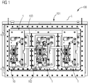
- Figure 1 illustrates a cross section side view of an embodiment of a transformer load tap changer 100 for setting a gear ratio comprising a tank 101 that encloses a fluid, and three power diverter switches arranged inside the tank 101 and immersed in the fluid.
- the transformer load tap changer 100 comprises drive motor drive shaft 102 and insulation shafts 103 to control the power diverter switches and their vacuum interrupter modules 1.
- a movement to operate the transformer load tap changer 100 is received through the motor drive shaft 102. That motor drive shaft 102 is connected to a motor drive unit, which is mounted to the tank 101.
- the motor drive shaft 102 is then connected to a bevel gear structure, which by the means of the insulation shafts 103 is distributing the movement to the three phases of the corresponding vacuum interrupter modules 1.
- FIG. 2 illustrates one power diverter switch assembly or vacuum interrupter module 1 of the transformer load tap changer 100 in a perspective view.
- the vacuum interrupter module 1 comprises an insulation plate 3 and current transformer 2 attached to the insulation plate 3.
- the insulation plate forms a support structure for the vacuum interrupter module 1 and may be composed of a rigid dielectric material, such as fiber-reinforced dielectric plastic.
- On a front side of the insulation plate 3 a bypass switch assembly and a vacuum interrupter assembly 10 is mounted.
- a back-side of the insulation plate 3 can be used for carrying copper bars used for schematic connection.
- Incoming motion from a selector is transferred to a cam end of a control cam 13 through the means of the insulation shafts 103.
- the control cam 13 is configured to actuate the bypass contacts 4 through corresponding bypass levers 5.
- the control cam 13 is configured to load and discharge a spring accumulator inside a driving mechanism 12.
- the vacuum interrupter module 1 comprises the vacuum interrupter assembly 10 including a vacuum interrupter 11 and the driving mechanism 12 that is coupled with the vacuum interrupter 11 and that is configured to drive opening and closing of electrical contacts of the vacuum interrupter 11.
- the transformer load tap changer 100 and the respective vacuum modules 1 may further include for each phase winding, a selector switch assembly and a bypass switch module.
- the selector switch assembly can be configured to make connections between taps, while the bypass switch module may be configured to connect the tap to a main power source.
- the vacuum interrupter module 1 safely carries the current between the tap and a main power circuit.
- a drive system is configured to move a selector switch, the bypass switch module and the vacuum interrupter module 1.
- the control cam 13 is coupled with the vacuum interrupter assembly 10 and is configured to drive the driving mechanism 12 to open and close the electrical contacts of the vacuum interrupter 11 (see Fig. 3 ).
- the driving mechanism 12 includes a driving rod 19 and a guiding tube 18 enclosing the driving rod 19 such that the driving rod 19 is axially movable inside the guiding tube 18 along a longitudinal axis L of the vacuum interrupter assembly 10.
- the respective vacuum interrupter assembly 10 further comprises a damping unit 20 coupled with the driving mechanism 12 and comprising a first chamber 21, a second chamber 22 and a piston 29 arranged there between with respect to the longitudinal axis L (see Figs. 4 and 5 ).
- the chambers 21, 22 are coupled with each other hydraulically and limited by the guiding tube 18, the piston 29 and a first disc 25 and a second disc 26 all arranged axially with respect to the longitudinal axis inside the guiding tube 18.
- the piston 29 is coupled with the driving rod 19 axially movable along the longitudinal axis L such that in interaction with the fluid the damping unit 20 provides hydraulic damping both when opening and when closing the electrical contacts of the vacuum interrupter 11 due to movement of the driving rod 19 and the piston 29 along the longitudinal axis L.
- the vacuum interrupter module 1 further comprises one or more driving springs 14, a locking mechanism 15, an adjusting system 16 and a locking system 17.
- the driving springs 14 accumulate the needed energy to provide proper switching speed of the vacuum interrupter module 1.
- the locking mechanism 15 and the locking system 17 are used for defining the two positions of the vacuum interrupter 11. Further, the locking system 17 is clamping the vacuum interrupter 11 toward the insulation plate 3.
- the adjusting system 16 is configured to adjust a contact gap and to provide solution for axial discrepancies during assembling of the vacuum interrupter module 1 and the vacuum interrupter assembly 10.
- the damping unit 20 is configured to provide reliable damping when the driving rod 19 is closing the vacuum interrupter 11 and when the driving rod 19 is opening the vacuum interrupter 11.
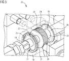
- the figures 4 and 5 each shows an enlarged perspective view of the damping unit 20 of the corresponding vacuum interrupter assembly 10 as circled in dashed lines in figure 3 .
- the damping unit 20 is configured such that it provides more damping when closing the electrical contacts of the vacuum interrupter 11 than when opening the same. Such a higher hydraulic damping force is achieved by the two different chambers 21, 22 and the discs 25, 26 comprising different orifices 27 and 28, respectively.
- the discs 25, 26 and the piston 29 realizes washers or bushings including a respective central opening the driving rod 19 is extending through.
- the discs 25 and 26 are fixedly connected to an inside surface of the guiding tube 18 whereas the piston 29 is fixedly connected to an outside surface of the driving rod 19.
- the inner surface of the guiding tube 18 and/or the outer surface of the driving rod 19 can comprise edges, protrusions and/or grooves to enable precise and stable arrangement of the discs 25, 26 and the piston 29, respectively.
- the first disc 23 comprises two orifices 27 and the second disc 24 comprises two orifices 28 each defining a fluid passage out and into the first chamber 21 and the second chamber 22.
- the orifices 27 and 28 of the first and the second disc 25 and 26 all are circularly limited and a respective diameter of the orifices 27 of the first disc 25 is smaller than a respective diameter of the orifice 28 of the second disc 26.
- the first disc 25 is arranged closer to the vacuum interrupter 11 than the second disc 26.
- the discs 25 and 26 are arranged inside the guiding tube 18 at opposite sides of the piston 29 with respect to the longitudinal axis L.
- the vacuum interrupter assembly 10 is configured such that when the piston 29 is driven towards the first disc 25 the electrical contacts of the vacuum interrupter are closed. Consequently, the vacuum interrupter assembly 10 is configured such that when the piston 29 is driven towards the second disc 26 the electrical contacts of the vacuum interrupter are opened.
- first disc 25 and its orifices 27 are configured to provide a predetermined hydraulic damping when closing the electrical contacts of the vacuum interrupter 11.
- second disc 26 and its orifices 28 are configured to provide a predetermined hydraulic damping when opening the electrical contacts of the vacuum interrupter 11.
- the guiding tube 18 comprises two recesses penetrating a wall of the guiding tube 18 defining a first channel 23 and a second channel 24 from the inside to the outside of the guiding tube 18.
- the first channel 23 is associated to the first chamber 21 and the second channel 24 is associated to the second chamber 22 such that a fluid passage is defined by the orifices 27 of the first disc 25, the first channel 23, the second channel 24 and the orifices 28 of the second disc 26.
- Due to movement of the driving rod 19 and the piston 29 a volume of one chamber 21, 22 is reduced whereas a volume of the other camber 22, 21 is increased.
- the piston 29 then closes the first channel 23 when closing the electrical contacts of the vacuum interrupter 11 and closes the second channel 24 when opening the electrical contacts of the vacuum interrupter 11.
- a size of the piston 29 as well as a size and a location of the first and the second channel 23, 24 in the wall of the guiding tube 18 are configured in coordination with each other to provide a predetermined hydraulic damping force in interaction with the fluid and a size of the orifices 27 and 28 in the discs 25 and 26.
- a size of the orifices 27 of the first disc 25, a size of the orifices 28 of the second disc 26 and a size of the first and the second channel 23 and 24 are configured in coordination with a viscosity of the fluid inside the tank 101.
- the discs 25 and 26, the piston 29 and the channels 23 and 24 are arranged and sized so that the piston 29 nearly closes both the first channel 23 and the second channel 24 in a middle position between the discs 25, 26 and the volume of the chambers 21 and 22 is roughly the same.
- Such a state might be illustrated in figure 4 .
- the piston 29 may have a thickness of a few millimeters, 8 mm for example, with respect to the longitudinal axis L.
- the thickness of the piston 29 is beneficially adapted to a stroke of the movable electrical contacts of the vacuum interrupter 11, which has a value of 4 mm, for example.
- a movable distance of the piston 29 inside the guiding tube 18 should also be adapted to the aforementioned stroke such that the piston can move reliably.
- a size of the orifices 27 of the first disc 25 and/or a size of the orifices 28 of the second disc 26 are configured to be smaller than a size of the first and/or the second channel 23, 24 on the periphery of the guiding tube 18 to reach a more smooth movement.
- the second channel 24 is closed by the piston 29 and the first channel 23 is predetermined opened in part.
- the piston 29 covers only one channel, i.e. an area of fluid leakage is larger, therefore at this point the speed is higher.
- the piston 29 If the movement the piston 29 is continued to close the electrical contacts it will close the first channel 23 and the second channel 24 then is opened in part, predetermined, to reach a desired braking effect, as an oil flow will be only through the two small orifices 27 of the first disk 25.
- the second channel 24, placed on the periphery of the guiding tube 18 is opened in part, thus preventing any braking effect that would be formed by a vacuum in the second chamber 22 inside the guiding tube 18 when moving the piston 29 towards the second disk 28.
- the sequence is the same but the speed is higher, and the orifices 28 of the second disk 26 are larger than the ones in the first disk 25.
- a respective center of the first and the second channel 23, 24 can have a distance of 5 mm from each other, wherein the first and the second channels 23, 24 may comprise a diameter of 4 mm each.
- the second channel 24 might be covered by the piston 29 such that a fluid-permeable area is reduced to 3 mm left with respect to the 4 mm diameter, for example.
- the first channel 23 might be covered by the piston 29 such that a fluid-permeable area is reduced to the half, viz. 2 mm left with respect to the 4 mm diameter, for example.
- the damping unit 20 is implemented in the guiding tube 18 of the driving mechanism 12 in the power diverter switch.
- the damping unit 20 merely comprises three elements and some adaptions on the guiding tube 18 and the driving rod 19 of the vacuum interrupter assembly 10.
- the exact positions of the holes or channels 23, 24 in the wall of the guiding tube 18 enables to provide an exact moment of the damping force and with default of the diameter of the orifices 27, 28 it is possible to achieve a desired reactance of the fluid - respectively damping force. Due to such a configuration, the damping unit 20 enables to beneficially influence the opening and closing speeds of the vacuum interrupter 11 and reduce unwanted bouncing effects during closing of the vacuum interrupter 11.
- the described vacuum interrupter assembly 10 provides a beneficial robustness and contributes to reduced manufacturability and maintenance criteria. Inter alia, this is achieved due to the specifically configured damping unit 20 which is immersed in a dielectric fluid.
- the electrical contacts of the vacuum interrupter 11 are opened and closed by the means of the driving mechanism 12 and the damping unit 20 is implemented in the driving mechanism 12.
- the damping unit 20 according to the illustrated embodiments is configured to provide more damping force when the driving rod 19 is closing the vacuum interrupter 11 than when the driving rod 19 is opening the vacuum interrupter 11. This can be achieved by the two hydraulic chambers 21, 22 and the discs 25, 26 with different orifices 27, 28.
Landscapes
- Engineering & Computer Science (AREA)
- Power Engineering (AREA)
- Driving Mechanisms And Operating Circuits Of Arc-Extinguishing High-Tension Switches (AREA)
- High-Tension Arc-Extinguishing Switches Without Spraying Means (AREA)
Abstract
Description
- The present disclosure is related to a vacuum interrupter assembly for a power diverter switch. The present disclosure is further related to a corresponding power diverter switch for a transformer load tap changer and to a transformer load tap changer.
- Vacuum interrupters are widely used in utility power transmission systems, power generation units and power-distribution systems for railways, for example. Therein, the vacuum interrupter realizes a switch of a medium-voltage circuit-breaker, generator circuit-breaker, or high-voltage circuit-breaker which uses electrical contacts in a vacuum to reliably separate the electrical contacts resulting in a metal vapour arc, which is quickly extinguished. In this respect, it is a challenge to provide stable and reliable mechanisms to transmit the motion from a driving cam to a contact rod of the vacuum interrupter and with respect to interacting components to keep wear low.
- Embodiments of the present disclosure relate to a vacuum interrupter assembly for a power diverter switch that enables secure and reliable switching of electrical contacts of the vacuum interrupter and contributes to an enhanced life of the vacuum interrupter. Further embodiments of the present disclosure relate to a corresponding power diverter switch for a transformer load tap changer and a transformer load tap changer including such a vacuum interrupter assembly.
- According to an embodiment, a vacuum interrupter assembly for a power diverter switch comprises a vacuum interrupter which is configured to open and close associated electrical contacts in a vacuum and a driving mechanism which is coupled with the vacuum interrupter and which is configured to drive opening and closing of the electrical contacts of the vacuum interrupter. The driving mechanism includes a driving rod and a guiding tube enclosing the driving rod such that the driving rod is axially movable along a longitudinal axis of the vacuum interrupter assembly arranged inside the guiding tube. The vacuum interrupter assembly further comprises a damping unit which is coupled with the driving mechanism and includes a first chamber, a second chamber and a piston arranged there between with respect to the longitudinal axis. The chambers are coupled with each other hydraulically and limited by the guiding tube and the piston. The piston is coupled with the driving rod axially movable along the longitudinal axis such that in interaction with a fluid the damping unit provides hydraulic damping both when opening and when closing the electrical contacts of the vacuum interrupter due to movement of the driving rod and the piston.
- Due to the described configuration a vacuum interrupter assembly is feasible that enables secure and reliable switching of electrical contacts of the vacuum interrupter and contributes to reduced wear of interacting components and an enhanced life of the vacuum interrupter and a corresponding power diverter switch. The damping unit realizes a cost-efficient design of a damping mechanism for precise vacuum interrupter control.
- It is a recognition of the present disclosure that conventional designs for power diverter switches and control of a vacuum interrupter often has a relatively complex mechanism with many moving parts and modules. These modules are interdependent and follow specific sequence, which lead to their complex design and further difficulties during manufacturing and maintenances.
- By use of the vacuum interrupter assembly of the present disclosure it is possible to counteract the aforementioned adverse effects at least. Due to the simple and compact design of the damping unit precise control of the movement of the driving rod in two directions is possible and the vacuum interrupter assembly contributes to reduce bouncing through closing of the vacuum interrupter and its electrical contacts resulting in reduced wear and enhanced assembly life.
- According to an embodiment the vacuum interrupter assembly further comprises a first disc and a second disc fixedly arranged to the guiding tube at opposite sides of the piston with respect to the longitudinal axis limiting the first and the second chamber respectively. Thus, the cambers and their hydraulic volume are defined by the fixed discs, a wall of the guiding tube and the movable piston.
- According to a further embodiment of the the vacuum interrupter assembly the first disc, the second disc and the piston all are arranged axially with respect to the longitudinal axis inside the guiding tube enclosing the driving rod. The first disc and the second disc are connected to the guiding tube whereas the piston is connected to the driving rod. Thus, the discs and the piston all are arranged radially between the guiding tube and the driving rod.
- Substantially, the guiding tube, the driving rod, the discs and the piston are formed rotationally symmetrical, for example.
- According to a further embodiment of the vacuum interrupter assembly the first disc and the second disc comprise at least one orifice each defining a respective fluid passage out and into the first chamber and the second chamber. Thus, due to movement of the driving rod and the piston thereon towards the first disc the volume of the first chamber is reduced and fluid is pressed out through the orifice of the first disc. Accordingly, due to movement of the driving rod and the piston thereon in the opposite direction towards the second disc the volume of the second chamber is reduced and fluid is pressed out through the orifice of the second disc. In this way, hydraulic damping force can be used to influence an opening and closing speed of the vacuum interrupter and to reduce unwanted bouncing effects during closing of the vacuum interrupter, in particular.
- Both the at least one orifice of the first and the one of the second disc can comprise a circular shape or are limited circularly by the corresponding disc, wherein a diameter of the orifice of the first disc can be smaller than a diameter of the orifice of the second disc. For example, the respective diameter of the orifice of the first disc is 1 mm and the respective diameter of the orifice of the second disc is 2.5 mm. Thus, a higher damping force can be provided in the direction of the first disc comprising the smaller orifice. According to the aforementioned embodiment, the first disc would be configured to provide hydraulic damping when closing the electrical contacts of the vacuum interrupter and the second disc when opening the electrical contacts.
- According to a further embedment of the vacuum interrupter assembly the guiding tube can also comprise two recesses. Such recesses can be configured to penetrate a wall of the guiding tube defining a first channel and a second channel associated to the first chamber and the second chamber respectively such that a fluid passage is defined by the orifice of the first disc, the first channel, the second channel and the orifice of the second disc. Thus, in view of an arrangement of the discs inside the guiding tube, a fluid could flow through the orifice of the first disc into the guiding tube and then through the first channel out of the guiding tube again. Accordingly, fluid from outside can flow through the second channel into the guiding tube and from inside through the orifice of the second disc to the outside again. To beneficially control the fluid flow and the hydraulic damping force, the piston is connected to the driving rod such that it closes the first channel when closing the electrical contacts of the vacuum interrupter and such that it closes the second channel when opening the electrical contacts of the vacuum interrupter due to movement of the driving rod. Thus, a distance of the first and the second channel is configured in coordination with a thickness of the piston with respect to the longitudinal axis.
- Furthermore, a size of the piston and/or a size and/or a location of the first and the second channel in the wall of the guiding tube can be configured in coordination with each other to provide a predetermined hydraulic damping force in interaction with a fluid that is intended to wash around the vacuum interrupter assembly and to flow inside and outside the guiding tube with respect to an operational state of the vacuum interrupter assembly.
- According to a further embodiment of the vacuum interrupter assembly at least one of the orifice of the first disc, the orifice of the second disc, the first channel and the second channel comprises a respective size configured in coordination with a viscosity of a fluid that is intended to flow inside and outside the guiding tube to provide a predetermined hydraulic damping force in interaction with the fluid with respect to an operational state of the vacuum interrupter assembly. The vacuum interrupter assembly is configured to be immersed in a predetermined fluid, for example a mineral transformer oil, inside a tank of a transformer load tap changer and thus, the size of the one or more intentionally implemented fluid openings can influence the hydraulic damping force depending on the viscosity of the fluid or the temperature of the fluid as well.
- According to an embodiment, a power diverter switch for a transformer load tap changer comprises an insulation plate, a control cam and an embodiment of the described vacuum interrupter assembly, which is coupled to both the insulation plate and the control cam. The control cam is configured to drive the driving mechanism of the vacuum interrupter assembly in order to open or close the electrical contacts of the vacuum interrupter.
- According to an embodiment, a transformer load tap changer for setting a gear ratio comprises a tank that encloses a fluid and at least one embodiment of the aforementioned power diverter switch which is arranged inside the tank immersed in the fluid.
- Such a configuration of a power diverter switch and a transformer load tap changer using an embodiment of the described vacuum interrupter assembly with an improved damper enables secure and reliable switching or separation of electrical contacts of the vacuum interrupter. As a result of that the power diverter switch and the transformer load tap changer comprise an embodiment of the vacuum interrupter, described features and characteristics of the vacuum interrupter are also disclosed with respect to the power diverter switch and the transformer load tap changer and vice versa. Thus, the present disclosure comprises several aspects, wherein every feature described with respect to one of the aspects is also disclosed herein with respect to the other aspect, even if the respective feature is not explicitly mentioned in the context of the specific aspect.
- With respect to an operational state assembled in the transformer the described configuration of the vacuum interrupter assembly and its specific hydraulic damper are immersed in a dielectric fluid and allows for beneficial control of opening and closing the electrical contacts of the vacuum interrupter. The damping unit enables precise and reliable operating mode of the vacuum interrupter and the transformer load the tap changer, respectively. The described configuration allows for a cost-effective assembly with an improved damping implemented in the driving mechanism and in addition one or more of the following advantageous effects:
- precise control of the movement of the driving rod in two directions
- reduced bouncing through closing of the vacuum interrupter
- control of the opening and closing speed of the vacuum interrupter
- clear and simple design
- use of the driving rod of the driving mechanism as a piston rod and piston for guiding element
- use an inner diameter of the guiding tube for a cylinder tube guiding the piston
- Exemplary embodiments are explained in the following with the aid of schematic drawings and reference numbers. The figures show:
- Figure 1
- an embodiment of a transformer load tap changer,
- Figure 2
- an embodiment of a vacuum interrupter module for the transformer load tap changer in a perspective view,
- Figure 3
- the vacuum interrupter module according to
figure 2 in a side view, - Figure 4
- a damping unit of a vacuum interrupter assembly of the vacuum interrupter module according to
figures 2 and3 , and - Figure 5
- the damping unit of the vacuum interrupter assembly in a further perspective view.
- The accompanying figures are included to provide a further understanding. It is to be understood that the embodiments shown in the figures are illustrative representations and are not necessarily drawn to scale. Identical reference numbers designate elements or components with identical functions. In so far as elements or components correspond to one another in terms of their function in different figures, the description thereof is not repeated for each of the following figures. For the sake of clarity elements might not appear with corresponding reference symbols in all figures possibly.
-
Figure 1 illustrates a cross section side view of an embodiment of a transformerload tap changer 100 for setting a gear ratio comprising atank 101 that encloses a fluid, and three power diverter switches arranged inside thetank 101 and immersed in the fluid. The transformerload tap changer 100 comprises drivemotor drive shaft 102 andinsulation shafts 103 to control the power diverter switches and theirvacuum interrupter modules 1. A movement to operate the transformerload tap changer 100 is received through themotor drive shaft 102. Thatmotor drive shaft 102 is connected to a motor drive unit, which is mounted to thetank 101. Themotor drive shaft 102 is then connected to a bevel gear structure, which by the means of theinsulation shafts 103 is distributing the movement to the three phases of the correspondingvacuum interrupter modules 1. -
Figure 2 illustrates one power diverter switch assembly orvacuum interrupter module 1 of the transformerload tap changer 100 in a perspective view. Thevacuum interrupter module 1 comprises aninsulation plate 3 andcurrent transformer 2 attached to theinsulation plate 3. The insulation plate forms a support structure for thevacuum interrupter module 1 and may be composed of a rigid dielectric material, such as fiber-reinforced dielectric plastic. On a front side of the insulation plate 3 a bypass switch assembly and avacuum interrupter assembly 10 is mounted. A back-side of theinsulation plate 3 can be used for carrying copper bars used for schematic connection. Incoming motion from a selector is transferred to a cam end of acontrol cam 13 through the means of theinsulation shafts 103. Thecontrol cam 13 is configured to actuate thebypass contacts 4 through corresponding bypass levers 5. At the same time thecontrol cam 13 is configured to load and discharge a spring accumulator inside adriving mechanism 12. - The
vacuum interrupter module 1 comprises thevacuum interrupter assembly 10 including avacuum interrupter 11 and thedriving mechanism 12 that is coupled with thevacuum interrupter 11 and that is configured to drive opening and closing of electrical contacts of thevacuum interrupter 11. The transformerload tap changer 100 and therespective vacuum modules 1 may further include for each phase winding, a selector switch assembly and a bypass switch module. The selector switch assembly can be configured to make connections between taps, while the bypass switch module may be configured to connect the tap to a main power source. During tap changes, thevacuum interrupter module 1 safely carries the current between the tap and a main power circuit. A drive system is configured to move a selector switch, the bypass switch module and thevacuum interrupter module 1. - The
control cam 13 is coupled with thevacuum interrupter assembly 10 and is configured to drive the drivingmechanism 12 to open and close the electrical contacts of the vacuum interrupter 11 (seeFig. 3 ). Thedriving mechanism 12 includes a drivingrod 19 and a guidingtube 18 enclosing the drivingrod 19 such that the drivingrod 19 is axially movable inside the guidingtube 18 along a longitudinal axis L of thevacuum interrupter assembly 10. - The respective
vacuum interrupter assembly 10 further comprises a dampingunit 20 coupled with thedriving mechanism 12 and comprising afirst chamber 21, asecond chamber 22 and apiston 29 arranged there between with respect to the longitudinal axis L (seeFigs. 4 and5 ). Thechambers tube 18, thepiston 29 and afirst disc 25 and asecond disc 26 all arranged axially with respect to the longitudinal axis inside the guidingtube 18. Thepiston 29 is coupled with the drivingrod 19 axially movable along the longitudinal axis L such that in interaction with the fluid the dampingunit 20 provides hydraulic damping both when opening and when closing the electrical contacts of thevacuum interrupter 11 due to movement of the drivingrod 19 and thepiston 29 along the longitudinal axis L. - According to the cross section view of the embodiment as illustrated in
figure 3 thevacuum interrupter module 1 further comprises one or more driving springs 14, alocking mechanism 15, an adjustingsystem 16 and alocking system 17. The driving springs 14 accumulate the needed energy to provide proper switching speed of thevacuum interrupter module 1. Thelocking mechanism 15 and thelocking system 17 are used for defining the two positions of thevacuum interrupter 11. Further, the lockingsystem 17 is clamping thevacuum interrupter 11 toward theinsulation plate 3. The adjustingsystem 16 is configured to adjust a contact gap and to provide solution for axial discrepancies during assembling of thevacuum interrupter module 1 and thevacuum interrupter assembly 10. The dampingunit 20 is configured to provide reliable damping when the drivingrod 19 is closing thevacuum interrupter 11 and when the drivingrod 19 is opening thevacuum interrupter 11. - The
figures 4 and5 each shows an enlarged perspective view of the dampingunit 20 of the correspondingvacuum interrupter assembly 10 as circled in dashed lines infigure 3 . The dampingunit 20 is configured such that it provides more damping when closing the electrical contacts of thevacuum interrupter 11 than when opening the same. Such a higher hydraulic damping force is achieved by the twodifferent chambers discs different orifices - The
discs piston 29 realizes washers or bushings including a respective central opening the drivingrod 19 is extending through. Thediscs tube 18 whereas thepiston 29 is fixedly connected to an outside surface of the drivingrod 19. Additionally, the inner surface of the guidingtube 18 and/or the outer surface of the drivingrod 19 can comprise edges, protrusions and/or grooves to enable precise and stable arrangement of thediscs piston 29, respectively. - The
first disc 23 comprises twoorifices 27 and thesecond disc 24 comprises twoorifices 28 each defining a fluid passage out and into thefirst chamber 21 and thesecond chamber 22. Theorifices second disc orifices 27 of thefirst disc 25 is smaller than a respective diameter of theorifice 28 of thesecond disc 26. According to the illustrated embodiments, thefirst disc 25 is arranged closer to thevacuum interrupter 11 than thesecond disc 26. Thediscs tube 18 at opposite sides of thepiston 29 with respect to the longitudinal axis L. - The
vacuum interrupter assembly 10 is configured such that when thepiston 29 is driven towards thefirst disc 25 the electrical contacts of the vacuum interrupter are closed. Consequently, thevacuum interrupter assembly 10 is configured such that when thepiston 29 is driven towards thesecond disc 26 the electrical contacts of the vacuum interrupter are opened. - Thus, the
first disc 25 and itsorifices 27 are configured to provide a predetermined hydraulic damping when closing the electrical contacts of thevacuum interrupter 11. Accordingly, thesecond disc 26 and itsorifices 28 are configured to provide a predetermined hydraulic damping when opening the electrical contacts of thevacuum interrupter 11. - Moreover, the guiding
tube 18 comprises two recesses penetrating a wall of the guidingtube 18 defining afirst channel 23 and asecond channel 24 from the inside to the outside of the guidingtube 18. Thefirst channel 23 is associated to thefirst chamber 21 and thesecond channel 24 is associated to thesecond chamber 22 such that a fluid passage is defined by theorifices 27 of thefirst disc 25, thefirst channel 23, thesecond channel 24 and theorifices 28 of thesecond disc 26. Due to movement of the drivingrod 19 and the piston 29 a volume of onechamber other camber piston 29 then closes thefirst channel 23 when closing the electrical contacts of thevacuum interrupter 11 and closes thesecond channel 24 when opening the electrical contacts of thevacuum interrupter 11. - A size of the
piston 29 as well as a size and a location of the first and thesecond channel tube 18 are configured in coordination with each other to provide a predetermined hydraulic damping force in interaction with the fluid and a size of theorifices discs orifices 27 of thefirst disc 25, a size of theorifices 28 of thesecond disc 26 and a size of the first and thesecond channel tank 101. For example, thediscs piston 29 and thechannels piston 29 nearly closes both thefirst channel 23 and thesecond channel 24 in a middle position between thediscs chambers figure 4 . - The
piston 29 may have a thickness of a few millimeters, 8 mm for example, with respect to the longitudinal axis L. The thickness of thepiston 29 is beneficially adapted to a stroke of the movable electrical contacts of thevacuum interrupter 11, which has a value of 4 mm, for example. Thus, a movable distance of thepiston 29 inside the guidingtube 18 should also be adapted to the aforementioned stroke such that the piston can move reliably. - For example, when moving the driving
rod 19 and thepiston 29 in the closing direction, a lower speed is desired. A size of theorifices 27 of thefirst disc 25 and/or a size of theorifices 28 of thesecond disc 26 are configured to be smaller than a size of the first and/or thesecond channel tube 18 to reach a more smooth movement. With respect to an end opening position, thesecond channel 24 is closed by thepiston 29 and thefirst channel 23 is predetermined opened in part. Thus, thepiston 29 covers only one channel, i.e. an area of fluid leakage is larger, therefore at this point the speed is higher. - If the movement the
piston 29 is continued to close the electrical contacts it will close thefirst channel 23 and thesecond channel 24 then is opened in part, predetermined, to reach a desired braking effect, as an oil flow will be only through the twosmall orifices 27 of thefirst disk 25. At the end closing position thesecond channel 24, placed on the periphery of the guidingtube 18 is opened in part, thus preventing any braking effect that would be formed by a vacuum in thesecond chamber 22 inside the guidingtube 18 when moving thepiston 29 towards thesecond disk 28. When moving in the opening direction again, the sequence is the same but the speed is higher, and theorifices 28 of thesecond disk 26 are larger than the ones in thefirst disk 25. - For example, a respective center of the first and the
second channel second channels second channel 24 might be covered by thepiston 29 such that a fluid-permeable area is reduced to 3 mm left with respect to the 4 mm diameter, for example. - Thus, with respect to a start closing position which is equivalent to the end opening position the
first channel 23 might be covered by thepiston 29 such that a fluid-permeable area is reduced to the half, viz. 2 mm left with respect to the 4 mm diameter, for example. - The damping
unit 20 is implemented in the guidingtube 18 of thedriving mechanism 12 in the power diverter switch. The dampingunit 20 merely comprises three elements and some adaptions on the guidingtube 18 and the drivingrod 19 of thevacuum interrupter assembly 10. Inter alia, the exact positions of the holes orchannels tube 18 enables to provide an exact moment of the damping force and with default of the diameter of theorifices unit 20 enables to beneficially influence the opening and closing speeds of thevacuum interrupter 11 and reduce unwanted bouncing effects during closing of thevacuum interrupter 11. - The described
vacuum interrupter assembly 10 provides a beneficial robustness and contributes to reduced manufacturability and maintenance criteria. Inter alia, this is achieved due to the specifically configured dampingunit 20 which is immersed in a dielectric fluid. The electrical contacts of thevacuum interrupter 11 are opened and closed by the means of thedriving mechanism 12 and the dampingunit 20 is implemented in thedriving mechanism 12. The dampingunit 20 according to the illustrated embodiments is configured to provide more damping force when the drivingrod 19 is closing thevacuum interrupter 11 than when the drivingrod 19 is opening thevacuum interrupter 11. This can be achieved by the twohydraulic chambers discs different orifices - The embodiments shown in the
Figures 1 to 5 as stated represent exemplary embodiments of the improvedvacuum interrupter assembly 10, the power diverter switch orvacuum interrupter module 1 and the transformerload tap changer 100, respectively. Therefore, they do not constitute a complete list of all embodiments. Actual arrangements may vary from the embodiments shown in the figures. -
- 1
- vacuum interrupter module
- 2
- current transformer
- 3
- insulation plate
- 4
- bypass contact
- 5
- bypass lever
- 10
- vacuum interrupter assembly
- 11
- vacuum interrupter
- 12
- driving mechanism
- 13
- control cam
- 14
- driving spring
- 15
- locking mechanism
- 16
- adjusting system
- 17
- locking system
- 18
- guiding tube
- 19
- driving rod
- 20
- damping unit
- 21
- first chamber
- 22
- second chamber
- 23
- first channel
- 24
- second channel
- 25
- first disc
- 26
- second disc
- 27
- first orifice
- 28
- second orifice
- 29
- piston
- 100
- transformer load tap changer
- 101
- tank
- 102
- motor drive shaft
- 103
- insulation shaft
- L
- longitudinal axis of the vacuum interrupter assembly
Claims (10)
- Vacuum interrupter assembly (10) for a power diverter switch, comprising:- a vacuum interrupter (11) which is configured to open and close associated electrical contacts in a vacuum,- a driving mechanism (12) which is coupled with the vacuum interrupter (11) and which is configured to drive opening and closing of the electrical contacts of the vacuum interrupter (11), wherein the driving mechanism (12) includes a driving rod (19) and a guiding tube (18) enclosing the driving rod (19) such that the driving rod (19) is axially movable inside the guiding tube (18) along a longitudinal axis (L) of the vacuum interrupter assembly (10), and- a damping unit (20) coupled with the driving mechanism (12) and comprising a first chamber (21), a second chamber (22) and a piston (29) arranged there between with respect to the longitudinal axis (L), wherein the chambers (21, 22) are coupled with each other hydraulically and limited by the guiding tube (18) and the piston (29), and wherein the piston (29) is coupled with the driving rod (19) axially movable along the longitudinal axis (L) such that in interaction with a fluid the damping unit (20) provides hydraulic damping both when opening and when closing the electrical contacts of the vacuum interrupter (11) due to movement of the driving rod (19) and the piston (29).
- Vacuum interrupter assembly (10) according to claim 1, comprising:
a first disc (23) and a second disc (24) fixedly arranged to the guiding tube (18) at opposite sides of the piston (29) with respect to the longitudinal axis (L) limiting the first and the second chamber (21, 22) respectively. - Vacuum interrupter assembly (10) according to claim 2, wherein the first disc (23), the second disc (24) and the piston (29) all are arranged axially with respect to the longitudinal axis (L) inside the guiding tube (18) and enclosing the driving rod (19) such that the first disc (23) and the second disc (24) are connected to the guiding tube (18) and the piston (29) is connected to the driving rod (19) and all are arranged radially between the guiding tube (18) and the driving rod (19).
- Vacuum interrupter assembly (10) according to claim 2 or 3, wherein the first disc (23) comprises at least one orifice (27) and the second disc (24) comprises at least one orifice (28) each defining a fluid passage out and into the first chamber (21) and the second chamber (22).
- Vacuum interrupter assembly (10) according to claim 4, wherein the at least one orifice (27) of the first disc (25) and the at least one orifice (28) of the second disc (26) both are circularly limited and a diameter of the orifice (27) of the first disc (25) is smaller than a diameter of the orifice (28) of the second disc (26), and wherein the first disc (25) is configured to provide hydraulic damping when closing the electrical contacts of the vacuum interrupter (11) .
- Vacuum interrupter assembly (10) according to any one of the preceding claims, wherein the guiding tube (18) comprises two recesses penetrating a wall of the guiding tube (18) defining a first channel (23) and a second channel (24) associated to the first chamber (21) and the second chamber (22) respectively such that a fluid passage is defined by the orifice (27) of the first disc (25), the first channel (23), the second channel (24) and the orifice (28) of the second disc (26), wherein the piston (29) is connected to the driving rod (19) such that it closes the first channel (23) when closing the electrical contacts of the vacuum interrupter (11) and it closes the second channel (24) when opening the electrical contacts of the vacuum interrupter (11) due to movement of the driving rod (19).
- Vacuum interrupter assembly (10) according to claim 6, wherein a size of the piston (29) and/or a size and/or a location of the first and the second channel (23, 24) in the wall of the guiding tube (18) are configured in coordination with each other to provide a predetermined hydraulic damping force in interaction with a fluid that is intended to flow inside and outside the guiding tube (18) with respect to an operational state of the vacuum interrupter assembly (10).
- Vacuum interrupter assembly (10) according to any one of the claims 4 to 7, wherein the orifice (27) of the first disc (25), the orifice (28) of the second disc (26), the first channel (23) and/or the second channel (24) comprise a respective size configured in coordination with a viscosity of a fluid that is intended to flow inside and outside the guiding tube (18) to provide a predetermined hydraulic damping force in interaction with the fluid with respect to an operational state of the vacuum interrupter assembly (10).
- Power diverter switch for a transformer load tap changer (100), comprising:- an insulation plate (3),- a control cam (13), and- a vacuum interrupter assembly (10) according to one of the preceding claims, which is coupled to both the insulation plate (3) and the control cam (13), wherein the control cam (13) is configured to drive the driving mechanism (12) of the vacuum interrupter assembly (10) to open and close the electrical contacts of the vacuum interrupter (11).
- Transformer load tap changer (100) for setting a gear ratio, comprising:- a tank (101) that encloses a fluid, and- at least one power diverter switch according to claim 9, which is arranged inside the tank (101) and immersed in the fluid.
Priority Applications (6)
| Application Number | Priority Date | Filing Date | Title |
|---|---|---|---|
| EP21170940.7A EP4084032B1 (en) | 2021-04-28 | 2021-04-28 | Vacuum interrupter assembly for a power diverter switch, power diverter switch for a transformer load tap changer and transformer load tap changer |
| EP21176871.8A EP4084033B1 (en) | 2021-04-28 | 2021-05-31 | Vacuum interrupter module for a tap changer, power diverter switch, and tap changer |
| PCT/EP2022/052583 WO2022228740A1 (en) | 2021-04-28 | 2022-02-03 | Vacuum interrupter assembly for a power diverter switch, power diverter switch for a transformer load tap changer and transformer load tap changer |
| KR1020237017412A KR102655004B1 (en) | 2021-04-28 | 2022-02-03 | Vacuum breaker assemblies for power converter switches, power converter switches for transformer load tap-changers and transformer load tap-changers |
| CN202280007450.6A CN116670794B (en) | 2021-04-28 | 2022-02-03 | Vacuum interrupter assembly for a power transfer switch, power transfer switch for a transformer load tap changer and transformer load tap changer |
| US17/669,557 US12131879B2 (en) | 2021-04-28 | 2022-02-11 | Vacuum interrupter module for a tap changer, power diverter switch, and tap changer |
Applications Claiming Priority (1)
| Application Number | Priority Date | Filing Date | Title |
|---|---|---|---|
| EP21170940.7A EP4084032B1 (en) | 2021-04-28 | 2021-04-28 | Vacuum interrupter assembly for a power diverter switch, power diverter switch for a transformer load tap changer and transformer load tap changer |
Publications (2)
| Publication Number | Publication Date |
|---|---|
| EP4084032A1 true EP4084032A1 (en) | 2022-11-02 |
| EP4084032B1 EP4084032B1 (en) | 2025-06-04 |
Family
ID=75728711
Family Applications (2)
| Application Number | Title | Priority Date | Filing Date |
|---|---|---|---|
| EP21170940.7A Active EP4084032B1 (en) | 2021-04-28 | 2021-04-28 | Vacuum interrupter assembly for a power diverter switch, power diverter switch for a transformer load tap changer and transformer load tap changer |
| EP21176871.8A Active EP4084033B1 (en) | 2021-04-28 | 2021-05-31 | Vacuum interrupter module for a tap changer, power diverter switch, and tap changer |
Family Applications After (1)
| Application Number | Title | Priority Date | Filing Date |
|---|---|---|---|
| EP21176871.8A Active EP4084033B1 (en) | 2021-04-28 | 2021-05-31 | Vacuum interrupter module for a tap changer, power diverter switch, and tap changer |
Country Status (5)
| Country | Link |
|---|---|
| US (1) | US12131879B2 (en) |
| EP (2) | EP4084032B1 (en) |
| KR (1) | KR102655004B1 (en) |
| CN (1) | CN116670794B (en) |
| WO (1) | WO2022228740A1 (en) |
Cited By (1)
| Publication number | Priority date | Publication date | Assignee | Title |
|---|---|---|---|---|
| CN118866600A (en) * | 2024-09-29 | 2024-10-29 | 帝森克罗德集团有限公司 | An energy-saving high-voltage vacuum circuit breaker |
Families Citing this family (1)
| Publication number | Priority date | Publication date | Assignee | Title |
|---|---|---|---|---|
| WO2025045329A1 (en) * | 2023-08-25 | 2025-03-06 | Hitachi Energy Ltd | Vacuum interrupter assembly for a power diverter switch, power diverter switch for a transformer load tap changer and transformer load tap changer |
Citations (4)
| Publication number | Priority date | Publication date | Assignee | Title |
|---|---|---|---|---|
| DE1170260B (en) * | 1958-06-10 | 1964-05-14 | Boge Gmbh | Hydraulic two-pipe telescopic damper, especially for motor vehicles |
| US3374320A (en) * | 1965-11-02 | 1968-03-19 | Bbc Brown Boveri & Cie | Tap-changing device for transformers having load current diverter means and improved hydraulic follower mechanism therefor |
| US9401249B2 (en) * | 2011-03-25 | 2016-07-26 | Abb Technology Ag | Tap changer |
| CN109559933A (en) * | 2018-11-16 | 2019-04-02 | 吴长兰 | High-voltage switch device |
Family Cites Families (40)
| Publication number | Priority date | Publication date | Assignee | Title |
|---|---|---|---|---|
| CA658038A (en) | 1963-02-19 | Wagner Electric Corporation | Tap changing apparatus | |
| DE639163C (en) | 1933-07-02 | 1936-11-30 | Siemens Schuckertwerke Akt Ges | Control switch with gear for step transformers |
| US2785242A (en) | 1955-06-13 | 1957-03-12 | Westinghouse Electric Corp | Tap-changers |
| US2891405A (en) | 1956-10-02 | 1959-06-23 | Mallory & Co Inc P R | Intermittent drive mechanism |
| US3066208A (en) | 1958-12-08 | 1962-11-27 | Wagner Electric Corp | Tap changing apparatus |
| US3155782A (en) | 1959-05-01 | 1964-11-03 | Mc Graw Edison Co | Switch actuating mechanism for controlled speed tap changer |
| US3045090A (en) | 1959-05-08 | 1962-07-17 | Mc Graw Edison Co | Tap changer movable contact |
| US3204176A (en) | 1961-04-26 | 1965-08-31 | Mc Graw Edison Co | Tap changing furnace transformer |
| US3436646A (en) | 1966-08-02 | 1969-04-01 | Westinghouse Electric Corp | Load tap changer systems including protective apparatus for monitoring the operation of the transfer switches |
| US3472981A (en) | 1966-08-05 | 1969-10-14 | Gen Electric | Pressure responsive protective means for vacuum type circuit interrupters immersed in liquid |
| US3532842A (en) | 1966-08-05 | 1970-10-06 | Gen Electric | Switch actuating and control mechanism for vacuum type electric circuit interrupters with lost-motion and bellows biasing means |
| US3720867A (en) * | 1972-02-04 | 1973-03-13 | Gen Electric | Fail safe vacuum type circuit interrupter and associated load current tap changer for electric induction apparatus |
| US5191179A (en) * | 1989-11-09 | 1993-03-02 | Cooper Power Systems, Inc. | Tap selector anti-arcing system |
| DE4009038A1 (en) | 1990-03-21 | 1991-09-26 | Reinhausen Maschf Scheubeck | METHOD AND ARRANGEMENT FOR A MONITORING SYSTEM FOR TAPE SWITCHES OF TAPE TRANSFORMERS |
| DE4009503A1 (en) | 1990-03-24 | 1991-09-26 | Reinhausen Maschf Scheubeck | STEPPER TRANSMISSION FOR STEPPERS OF STEPPING TRANSFORMERS |
| DE4011019C1 (en) | 1990-04-05 | 1991-12-05 | Maschinenfabrik Reinhausen Gmbh, 8400 Regensburg, De | |
| DE4034126C1 (en) | 1990-10-26 | 1992-03-05 | Maschinenfabrik Reinhausen Gmbh, 8400 Regensburg, De | |
| DE4126824C1 (en) | 1991-08-14 | 1993-04-08 | Maschinenfabrik Reinhausen Gmbh, 8400 Regensburg, De | |
| US5594223A (en) * | 1993-12-07 | 1997-01-14 | Fuji Electric Co., Ltd. | Vacuum switch bulb type change over switch for on-load tap changer |
| US5589675A (en) * | 1994-04-08 | 1996-12-31 | Trinetics, Inc. | Vacuum switch |
| DE19743865C1 (en) | 1997-10-04 | 1999-04-15 | Reinhausen Maschf Scheubeck | Tap changer |
| DE19743864C1 (en) | 1997-10-04 | 1999-04-15 | Reinhausen Maschf Scheubeck | Tap changer |
| US6693247B1 (en) | 2000-06-09 | 2004-02-17 | Mcgraw-Edison Company | Load tap changer with direct drive and brake |
| US8430136B2 (en) | 2011-03-03 | 2013-04-30 | Abb Technology Ag | Oil catch tray for load tap changer tank |
| US8686302B2 (en) | 2011-03-25 | 2014-04-01 | Abb Technology Ag | Selector switch assembly for load tap changer |
| EP2689441B1 (en) | 2011-03-25 | 2015-01-07 | ABB Technology AG | A tap changer with improved swicth construction |
| WO2012134963A1 (en) | 2011-03-25 | 2012-10-04 | Abb Technology Ag | Tap changer having an improved vacuum interrupter actuating assembly |
| WO2012134977A1 (en) | 2011-03-25 | 2012-10-04 | Abb Technology Ag | Tap changer having a vaccum interrupter assembly with an improved damper |
| WO2012135213A1 (en) | 2011-03-27 | 2012-10-04 | Abb Technology Ag | Tap changer with an improved monitoring system |
| WO2012135209A1 (en) | 2011-03-27 | 2012-10-04 | Abb Technology Ag | Tap changer with an improved drive system |
| BR112014003662B1 (en) * | 2011-08-17 | 2021-05-11 | Hubbell Incorpora Ted | switch for an electrical circuit |
| DE102011113718A1 (en) * | 2011-09-17 | 2013-03-21 | Maschinenfabrik Reinhausen Gmbh | OLTC |
| DE102012202327B4 (en) * | 2012-02-16 | 2015-01-08 | Maschinenfabrik Reinhausen Gmbh | On-load tap-changer with at least two vacuum interrupters and drive for a diverter switch with at least two vacuum interrupters |
| CN102709106B (en) * | 2012-05-17 | 2015-03-11 | 上海华明电力设备集团有限公司 | Vacuum arc extinction change-over selector |
| DE102012105152B4 (en) * | 2012-06-14 | 2015-11-12 | Maschinenfabrik Reinhausen Gmbh | On-load tap-changer for uninterrupted switching between different winding taps of a tapped transformer |
| DE102013102299B4 (en) * | 2013-03-08 | 2014-12-04 | Maschinenfabrik Reinhausen Gmbh | linear voters |
| DE102014112764A1 (en) * | 2014-09-04 | 2016-03-10 | Maschinenfabrik Reinhausen Gmbh | Switching arrangement for a regulating transformer, in particular polarity switch |
| DE102014112763A1 (en) * | 2014-09-04 | 2016-03-10 | Maschinenfabrik Reinhausen Gmbh | Switching arrangement for a regulating transformer, in particular preselector |
| ES2709770T3 (en) * | 2015-04-21 | 2019-04-17 | Ormazabal Corporate Tech A I E | On-load tap changer device |
| DE102016104499B3 (en) * | 2016-03-11 | 2017-04-27 | Maschinenfabrik Reinhausen Gmbh | Selector for an on-load tap-changer and on-load tap-changer with diverter switch and selector |
-
2021
- 2021-04-28 EP EP21170940.7A patent/EP4084032B1/en active Active
- 2021-05-31 EP EP21176871.8A patent/EP4084033B1/en active Active
-
2022
- 2022-02-03 KR KR1020237017412A patent/KR102655004B1/en active Active
- 2022-02-03 WO PCT/EP2022/052583 patent/WO2022228740A1/en not_active Ceased
- 2022-02-03 CN CN202280007450.6A patent/CN116670794B/en active Active
- 2022-02-11 US US17/669,557 patent/US12131879B2/en active Active
Patent Citations (4)
| Publication number | Priority date | Publication date | Assignee | Title |
|---|---|---|---|---|
| DE1170260B (en) * | 1958-06-10 | 1964-05-14 | Boge Gmbh | Hydraulic two-pipe telescopic damper, especially for motor vehicles |
| US3374320A (en) * | 1965-11-02 | 1968-03-19 | Bbc Brown Boveri & Cie | Tap-changing device for transformers having load current diverter means and improved hydraulic follower mechanism therefor |
| US9401249B2 (en) * | 2011-03-25 | 2016-07-26 | Abb Technology Ag | Tap changer |
| CN109559933A (en) * | 2018-11-16 | 2019-04-02 | 吴长兰 | High-voltage switch device |
Cited By (1)
| Publication number | Priority date | Publication date | Assignee | Title |
|---|---|---|---|---|
| CN118866600A (en) * | 2024-09-29 | 2024-10-29 | 帝森克罗德集团有限公司 | An energy-saving high-voltage vacuum circuit breaker |
Also Published As
| Publication number | Publication date |
|---|---|
| CN116670794A (en) | 2023-08-29 |
| EP4084032B1 (en) | 2025-06-04 |
| CN116670794B (en) | 2025-02-18 |
| EP4084033B1 (en) | 2025-05-07 |
| WO2022228740A1 (en) | 2022-11-03 |
| KR20230084311A (en) | 2023-06-12 |
| EP4084033A1 (en) | 2022-11-02 |
| US12131879B2 (en) | 2024-10-29 |
| KR102655004B1 (en) | 2024-04-05 |
| US20220384123A1 (en) | 2022-12-01 |
Similar Documents
| Publication | Publication Date | Title |
|---|---|---|
| KR102446586B1 (en) | On-load tap-changer | |
| RU2256975C2 (en) | Power switch | |
| EP3104387B1 (en) | Selector switch assembly for load tap changer | |
| EP2689443B1 (en) | Tap changer having a vacuum interrupter assembly with an improved damper | |
| EP2689444B1 (en) | Tap changer having an improved vacuum interrupter actuating assembly | |
| EP4084032B1 (en) | Vacuum interrupter assembly for a power diverter switch, power diverter switch for a transformer load tap changer and transformer load tap changer | |
| EP2689442B1 (en) | An improved tap changer | |
| US9640341B2 (en) | On-load tap changer | |
| US10102990B2 (en) | On-load tap changer | |
| KR102642659B1 (en) | Switching systems for on-load tap-changers, on-load tap-changers and methods for switching tap connections in on-load tap-changers | |
| US20150008104A1 (en) | On-load tap changer with two vacuum interrupters and drive therefor | |
| EP3989253B1 (en) | System for controlling a vacuum interrupter for a power diverter switch, a power diverter switch and an on-load tap changer | |
| EP3155627B1 (en) | Interrupter driven resistor switch assembly | |
| EP3419039B1 (en) | Electric high-voltage circuit breaker | |
| KR102777220B1 (en) | Load transfer switch for on-load tap changer, and on-load tap changer | |
| WO2025045329A1 (en) | Vacuum interrupter assembly for a power diverter switch, power diverter switch for a transformer load tap changer and transformer load tap changer | |
| EP2591484B1 (en) | Method and system for a pre-selector in a tap changer | |
| EP4654236A1 (en) | Bypass contact system, vacuum interrupter module and tap changer | |
| US20040061504A1 (en) | Vacuum circuit-breaker and a method for controlling the same | |
| KR102835654B1 (en) | System for controlling vacuum interrupter for power diverter switch, power diverter switch and on-load tap changer | |
| JP3900510B2 (en) | Load tap changer | |
| HK1228565B (en) | Load selector | |
| HK40008027B (en) | A spring operated actuator | |
| HK1228565A1 (en) | Load selector |
Legal Events
| Date | Code | Title | Description |
|---|---|---|---|
| PUAI | Public reference made under article 153(3) epc to a published international application that has entered the european phase |
Free format text: ORIGINAL CODE: 0009012 |
|
| STAA | Information on the status of an ep patent application or granted ep patent |
Free format text: STATUS: THE APPLICATION HAS BEEN PUBLISHED |
|
| AK | Designated contracting states |
Kind code of ref document: A1 Designated state(s): AL AT BE BG CH CY CZ DE DK EE ES FI FR GB GR HR HU IE IS IT LI LT LU LV MC MK MT NL NO PL PT RO RS SE SI SK SM TR |
|
| STAA | Information on the status of an ep patent application or granted ep patent |
Free format text: STATUS: REQUEST FOR EXAMINATION WAS MADE |
|
| 17P | Request for examination filed |
Effective date: 20230428 |
|
| RBV | Designated contracting states (corrected) |
Designated state(s): AL AT BE BG CH CY CZ DE DK EE ES FI FR GB GR HR HU IE IS IT LI LT LU LV MC MK MT NL NO PL PT RO RS SE SI SK SM TR |
|
| P01 | Opt-out of the competence of the unified patent court (upc) registered |
Effective date: 20230527 |
|
| RAP1 | Party data changed (applicant data changed or rights of an application transferred) |
Owner name: HITACHI ENERGY LTD |
|
| REG | Reference to a national code |
Ref country code: DE Free format text: PREVIOUS MAIN CLASS: H01H0001500000 Ref legal event code: R079 Ref document number: 602021031619 Country of ref document: DE Ipc: H01H0009000000 |
|
| GRAP | Despatch of communication of intention to grant a patent |
Free format text: ORIGINAL CODE: EPIDOSNIGR1 |
|
| STAA | Information on the status of an ep patent application or granted ep patent |
Free format text: STATUS: GRANT OF PATENT IS INTENDED |
|
| RIC1 | Information provided on ipc code assigned before grant |
Ipc: H01H 33/666 20060101ALN20241119BHEP Ipc: H01H 3/42 20060101ALI20241119BHEP Ipc: H01F 29/04 20060101ALI20241119BHEP Ipc: H01H 9/00 20060101AFI20241119BHEP |
|
| INTG | Intention to grant announced |
Effective date: 20241205 |
|
| GRAS | Grant fee paid |
Free format text: ORIGINAL CODE: EPIDOSNIGR3 |
|
| GRAA | (expected) grant |
Free format text: ORIGINAL CODE: 0009210 |
|
| STAA | Information on the status of an ep patent application or granted ep patent |
Free format text: STATUS: THE PATENT HAS BEEN GRANTED |
|
| AK | Designated contracting states |
Kind code of ref document: B1 Designated state(s): AL AT BE BG CH CY CZ DE DK EE ES FI FR GB GR HR HU IE IS IT LI LT LU LV MC MK MT NL NO PL PT RO RS SE SI SK SM TR |
|
| REG | Reference to a national code |
Ref country code: GB Ref legal event code: FG4D |
|
| REG | Reference to a national code |
Ref country code: CH Ref legal event code: EP |
|
| REG | Reference to a national code |
Ref country code: DE Ref legal event code: R096 Ref document number: 602021031619 Country of ref document: DE |
|
| REG | Reference to a national code |
Ref country code: IE Ref legal event code: FG4D |
|
| REG | Reference to a national code |
Ref country code: NL Ref legal event code: MP Effective date: 20250604 |
|
| PG25 | Lapsed in a contracting state [announced via postgrant information from national office to epo] |
Ref country code: ES Free format text: LAPSE BECAUSE OF FAILURE TO SUBMIT A TRANSLATION OF THE DESCRIPTION OR TO PAY THE FEE WITHIN THE PRESCRIBED TIME-LIMIT Effective date: 20250604 Ref country code: FI Free format text: LAPSE BECAUSE OF FAILURE TO SUBMIT A TRANSLATION OF THE DESCRIPTION OR TO PAY THE FEE WITHIN THE PRESCRIBED TIME-LIMIT Effective date: 20250604 |
|
| REG | Reference to a national code |
Ref country code: LT Ref legal event code: MG9D |
|
| PG25 | Lapsed in a contracting state [announced via postgrant information from national office to epo] |
Ref country code: NO Free format text: LAPSE BECAUSE OF FAILURE TO SUBMIT A TRANSLATION OF THE DESCRIPTION OR TO PAY THE FEE WITHIN THE PRESCRIBED TIME-LIMIT Effective date: 20250904 Ref country code: GR Free format text: LAPSE BECAUSE OF FAILURE TO SUBMIT A TRANSLATION OF THE DESCRIPTION OR TO PAY THE FEE WITHIN THE PRESCRIBED TIME-LIMIT Effective date: 20250905 |
|
| PG25 | Lapsed in a contracting state [announced via postgrant information from national office to epo] |
Ref country code: PL Free format text: LAPSE BECAUSE OF FAILURE TO SUBMIT A TRANSLATION OF THE DESCRIPTION OR TO PAY THE FEE WITHIN THE PRESCRIBED TIME-LIMIT Effective date: 20250604 |
|
| PG25 | Lapsed in a contracting state [announced via postgrant information from national office to epo] |
Ref country code: HR Free format text: LAPSE BECAUSE OF FAILURE TO SUBMIT A TRANSLATION OF THE DESCRIPTION OR TO PAY THE FEE WITHIN THE PRESCRIBED TIME-LIMIT Effective date: 20250604 |
|
| PG25 | Lapsed in a contracting state [announced via postgrant information from national office to epo] |
Ref country code: RS Free format text: LAPSE BECAUSE OF FAILURE TO SUBMIT A TRANSLATION OF THE DESCRIPTION OR TO PAY THE FEE WITHIN THE PRESCRIBED TIME-LIMIT Effective date: 20250904 |
|
| PG25 | Lapsed in a contracting state [announced via postgrant information from national office to epo] |
Ref country code: LV Free format text: LAPSE BECAUSE OF FAILURE TO SUBMIT A TRANSLATION OF THE DESCRIPTION OR TO PAY THE FEE WITHIN THE PRESCRIBED TIME-LIMIT Effective date: 20250604 |
|
| PG25 | Lapsed in a contracting state [announced via postgrant information from national office to epo] |
Ref country code: NL Free format text: LAPSE BECAUSE OF FAILURE TO SUBMIT A TRANSLATION OF THE DESCRIPTION OR TO PAY THE FEE WITHIN THE PRESCRIBED TIME-LIMIT Effective date: 20250604 |
|
| PG25 | Lapsed in a contracting state [announced via postgrant information from national office to epo] |
Ref country code: PT Free format text: LAPSE BECAUSE OF FAILURE TO SUBMIT A TRANSLATION OF THE DESCRIPTION OR TO PAY THE FEE WITHIN THE PRESCRIBED TIME-LIMIT Effective date: 20251006 |
|
| REG | Reference to a national code |
Ref country code: AT Ref legal event code: MK05 Ref document number: 1801223 Country of ref document: AT Kind code of ref document: T Effective date: 20250604 |
|
| PG25 | Lapsed in a contracting state [announced via postgrant information from national office to epo] |
Ref country code: IS Free format text: LAPSE BECAUSE OF FAILURE TO SUBMIT A TRANSLATION OF THE DESCRIPTION OR TO PAY THE FEE WITHIN THE PRESCRIBED TIME-LIMIT Effective date: 20251004 |
|
| PG25 | Lapsed in a contracting state [announced via postgrant information from national office to epo] |
Ref country code: SM Free format text: LAPSE BECAUSE OF FAILURE TO SUBMIT A TRANSLATION OF THE DESCRIPTION OR TO PAY THE FEE WITHIN THE PRESCRIBED TIME-LIMIT Effective date: 20250604 Ref country code: AT Free format text: LAPSE BECAUSE OF FAILURE TO SUBMIT A TRANSLATION OF THE DESCRIPTION OR TO PAY THE FEE WITHIN THE PRESCRIBED TIME-LIMIT Effective date: 20250604 |
|
| PG25 | Lapsed in a contracting state [announced via postgrant information from national office to epo] |
Ref country code: CZ Free format text: LAPSE BECAUSE OF FAILURE TO SUBMIT A TRANSLATION OF THE DESCRIPTION OR TO PAY THE FEE WITHIN THE PRESCRIBED TIME-LIMIT Effective date: 20250604 |
|
| PG25 | Lapsed in a contracting state [announced via postgrant information from national office to epo] |
Ref country code: EE Free format text: LAPSE BECAUSE OF FAILURE TO SUBMIT A TRANSLATION OF THE DESCRIPTION OR TO PAY THE FEE WITHIN THE PRESCRIBED TIME-LIMIT Effective date: 20250604 |
|
| PG25 | Lapsed in a contracting state [announced via postgrant information from national office to epo] |
Ref country code: SK Free format text: LAPSE BECAUSE OF FAILURE TO SUBMIT A TRANSLATION OF THE DESCRIPTION OR TO PAY THE FEE WITHIN THE PRESCRIBED TIME-LIMIT Effective date: 20250604 |
|
| PG25 | Lapsed in a contracting state [announced via postgrant information from national office to epo] |
Ref country code: IT Free format text: LAPSE BECAUSE OF FAILURE TO SUBMIT A TRANSLATION OF THE DESCRIPTION OR TO PAY THE FEE WITHIN THE PRESCRIBED TIME-LIMIT Effective date: 20250604 |
|
| REG | Reference to a national code |
Ref country code: DE Ref legal event code: R097 Ref document number: 602021031619 Country of ref document: DE |
|
| PLBE | No opposition filed within time limit |
Free format text: ORIGINAL CODE: 0009261 |
|
| STAA | Information on the status of an ep patent application or granted ep patent |
Free format text: STATUS: NO OPPOSITION FILED WITHIN TIME LIMIT |
|
| PG25 | Lapsed in a contracting state [announced via postgrant information from national office to epo] |
Ref country code: DK Free format text: LAPSE BECAUSE OF FAILURE TO SUBMIT A TRANSLATION OF THE DESCRIPTION OR TO PAY THE FEE WITHIN THE PRESCRIBED TIME-LIMIT Effective date: 20250604 |
|
| REG | Reference to a national code |
Ref country code: CH Ref legal event code: L10 Free format text: ST27 STATUS EVENT CODE: U-0-0-L10-L00 (AS PROVIDED BY THE NATIONAL OFFICE) Effective date: 20260416 |
|
| 26N | No opposition filed |
Effective date: 20260305 |